OC-1 AWCS-II Option Card
OC-1 AWCS-II Option Card Service Manual â Bose
OC-1 AWCS-II Option Card Service Manual â Bose

Create successful ePaper yourself
Turn your PDF publications into a flip-book with our unique Google optimized e-Paper software.
®<strong>OC</strong>-1 <strong>AWCS</strong>-<strong>II</strong> <strong>Option</strong> <strong>Card</strong>©1994 Bose Corporation Service Manual
TABLE OF CONTENTS1. SPECIFICATIONS.................................................................................................... 22. THEORY OF OPERATION....................................................................................... 33. EQ CURVES............................................................................................................. 54. BL<strong>OC</strong>K DIAGRAM.................................................................................................... 85. INSTALLATION INSTRUCTIONS........................................................................... 96. TEST PR<strong>OC</strong>EDURES.............................................................................................. 127. PARTS LIST ..........................................................................................................16CAUTION: THE <strong>OC</strong>-1 OPTION CARD CONTAINS NO USER SER-VICEABLE PARTS. TO PREVENT WARRANTY INFRACTIONS, REFERSERVICING TO WARRANTY SERVICE STATIONS OR FACTORY SERVICE.PROPRIETARY INFORMATIONTHIS D<strong>OC</strong>UMENT CONTAINS PROPRIETARY INFORMATION OFBOSE ® CORPORATION WHICH IS BEING FURNISHED ONLY FORTHE PURPOSE OF SERVICING THE IDENTIFIED BOSE PRODUCTBY AN AUTHORIZED BOSE SERVICE CENTER OR OWNER OF THEBOSE PRODUCT, AND SHALL NOT BE REPRODUCED OR USEDFOR ANY OTHER PURPOSE.1
<strong>OC</strong>-1 SPECIFICATIONSDimensions:.63" Hx1.29"Wx8.98"D(1.6x3.3x22.8 cm)Weight: .09 lbs. (.042 kg.)Input/Output:2 audio inputs,Channel 1 and 2 highfrequency outputs, bass channnel outputInput Impedance: 482 kΩ (nominal)(feedback input)Output Level: 5.0 Vrms into 10 kΩCrossover Frequency: 125 Hz,Roll-off slope: 24 dB/oct.Output Noise: ≤ 40µV (A-weighted)Channel Separation:50 dB (min.) @ 5 kHz2
THEORY OF OPERATIONOverviewThe <strong>OC</strong>-1 is a small plug-in module for use with Bose 502, 402, and 802 ® <strong>II</strong> controllers. The<strong>OC</strong>-1 allows the use of the Cannon bass loudspeaker with these controllers and theirloudspeakers. Refer to the block diagram, equalization curves and <strong>OC</strong>-1 schematic for furtherinformation.The <strong>OC</strong>-1 provides three major functions:A. Low frequency equalization.B. Crossover filtering of the high frequency signals.C. Protection of the Cannon against excessive power.1. Low Frequency Equalization CircuitU5's four op-amp stages provide low-pass crossover filtering, high-pass filtering to eliminatesubsonic material, and frequency contouring to optimize the overall response.2. High Frequency Equalization CircuitU3, section 1 and U5, section 2 provide two channels of high-pass filtering to remove bass fromthe main loudspeakers.3. Protection CircuitThe protection circuit consists of a compressor and a mute circuit. The protection circuit isconnected so that it can monitor the low frequency voltage applied to the Cannon driver. When thisvoltage exceeds the power limit defined for the driver, a compressor begins to reduce the gain inthe low frequency path so that the power does not continue to rise.4. Compressor CircuitThe compressor consists of the following functional blocks:A. Differential input bufferB. Full-wave peak detector/comparatorC. Averaging circuitD. Voltage-controlled amplifier (VCA)The differential input buffer (U1 section 1) features protection against Radio FrequencyInterference (RFI), Electrostatic Discharge (ESD), and overvoltage. It has a gain which is muchless than 1 so that it can attenuate the high level signals coming from the Cannon (over 40 volts atfull power).3
U4, sections 1 and 2 form a full-wave peak detector. When the input to these stages exceeds+/-2V peak, the outputs go high and a control voltage is created in the averaging circuit (C27, C28,etc.). The averaging circuit captures peaks with a short attack time and holds them with a longerrelease time. U2, section 2 inverts and scales the averaged control voltage and applies it to theVCA control input.U7 is a current-in/current-out VCA which is controlled by the voltage on pin 2.5. Mute CircuitThe mute circuit acts as a watchdog, and prevents the Cannon from operating unless thefeedback signal from the Cannon is connected properly to the controller/<strong>OC</strong>-1 protection input.When the mute circuit detects that no audio has occurred for about two minutes, it reduces the gainin the low frequency path.The mute circuit consists of a gain stage and a comparator. U1, section 2 amplifies the signal fromthe protection circuit differential input, and U2, section 1 compares it to a reference. When thesensed level exceeds the threshold, a control voltage (generated in U2, section 2) causes U2,section 1 to go from high to low and reduces the compressor gain by about 40 dB.4
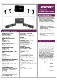
Output is measured from U3 pin 7 or U6 pin 1. Controls are set at:: Mode 4 (<strong>Option</strong>),Output Mode: Normal, Low Frequency Level: 0 dB, and Input Level: +4 dB.Figure 1. High Frequency EQOutput is measured from U5 pin 14. Controls are set as in Figure 1.Figure 2. EQA + EQB5
Output is measured from U5 pin 1. Controls are set as in Figure 1.Figure 3. EQA + EQB + EQCOutput is measured from U5 pin 7. Controls are set as in Figure 1.Figure 4. EQA + EQB + EQC + EQD6
Output is measured from U3 pin 1. Controls are set as in Figure 1.Figure 5. EQA + EQB + EQC + EQD + VCA7
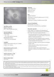
Figure 6. <strong>OC</strong>-1 Block Diagram8
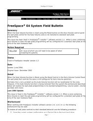
<strong>OC</strong>-1 Installation ProceduresNOTE: The information included here is to aidthe technician in setting up the <strong>OC</strong>-1 beforedoing any troubleshooting. These proceduresare provided in more depth in the <strong>OC</strong>-1 Owner'sGuide (P/N 176007).<strong>OC</strong>-1 <strong>Option</strong> <strong>Card</strong>Internal ProtectionCircuit HarnessExternal ProtectionCircuit HarnessFigure 7. <strong>OC</strong>-1 <strong>Option</strong> <strong>Card</strong> and Harnesses1. Installing the Internal Protection CircuitHarnessA. Turn the controller so that its rear panelfaces you. See Figure 8.B. Remove 4 phillips-head screws.C. Slide the cover towards you and lift awayfrom the controller.D. Find the plastic plug in the controller'srear panel (Figure 9). Pinch the top lock taband push the plug partially out (Figure 9A).Release the tab and pull the plug completelyout.9AFigure 8. Cover and screw removalFigure 9. Plastic plug removal9
10AFlat side of barrel10B10CFigure 10. Internal Harness ConnectionE. Remove the lock nut and washer from theharness (Figure 10A).F. Thread the harness through the rearpanel (white connector first).G. Turn the barrel connector so that its flatside matches the flat side of the hole in thecontroller. The connector should sit firmlyagainst the outside of the rear panel (Figure10B).H. Replace the lock nut and washer on theharness inside the rear panel. Tighten firmlywith needle nose pliers (Figure 10C).2. Connecting the <strong>OC</strong>-1 to the controllerNOTE: The controller's rear panel shouldface you and the internal harness should beinside.A. Turn the <strong>OC</strong>-1 PCB so that its componentside faces you.B. Connect the harness to J1 on the <strong>OC</strong>-1PCB (Figure 11).C. Plug the PCB into the connectorreceptacles located on the controller's PCB.See Figure 12 for proper orientation.3. Installing the External Protection CircuitHarnessA. Attach the external harness to the internalharness connector (Figure 13) by turningthe notch on the harness to the right.B. Hand tighten the lock nut on the externalharness.Figure 11. System Controller ConnectionFigure 12. <strong>OC</strong>-1 connected to controller PCB10
Figure 13. External Harness ConnectionC. Connect the harness's other end to the speaker terminals on your amplifier with either screwlugs (Figure 14A) or a banana plug (Figure 14B). Connect the red wire to the positive (+)terminal and the black wire to the negative (-) terminal.NOTE: Figure 15 shows a typical system hookup.Figure 14A. Screw terminalFigure 14B. Banana plugFigure 15. Complete system hookup11
Test Setup<strong>OC</strong>-1 Test ProceduresInput Connections: Connect an oscillator to thepositive (+) and negative (-) input terminals forChannels 1 or 2. These procedures assume thatthe person performing these tests is using testequipment with unbalanced inputs and outputs.See Figure 16 for connection information. Also,refer to Figure 15 for a system hookup diagram.Output Connections: Connect test equipment tothe positive (+) and negative (-) output terminalsfor Channels 1 or 2 (low and high frequencyoutputs).All tests should be performed for bothchannels.All test equipment must be isolated fromground (floated).See Figure 17 for a picture of the controller'sback panel.• Output mode switch should be set atnormal• Input switches should be set at +4 dB• Low frequency level potentiometer shouldbe set at 0 dB**IMPORTANT NOTE**Install the external protection circuit harness for alltests. Otherwise, the controller's bass channel (as asafety measure) will shut down.1. Frequency Response of High Frequency (HF)OutputA. Apply a 100 mVrms, 600 Hz signal to thecontrollers's input terminals and reference yourdB meter to this frequency.The controls on the back panel should be set asfollows:• Mode switch should be set at 4 (<strong>Option</strong>)B. Measure the frequency response across theHF outputs according to the chart below. Thischart provides responses for the 402, 502, and802 <strong>II</strong> controllers (with the option card installed).Frequency (Hz) 402 Controller 502 Controller 802 ® <strong>II</strong> ControllerResponse (dB) Response (dB) Response (dB)40 -29.2 ± 1.5 dB -23.5 ± 1.5 dB -17.57 ± 1.5 dB80 -8.3 ± 1.5 dB - 5.6 ± 1.5 dB -1.84 ± 1.5 dB100 -3.0 ± 1.5 dB +0.8 ± 1 .5 dB +2.0 ± 1.5 dB120 0 dB +1.6 ± 1 .5 dB +4.0 ± 1.5 dB150 +1.83 ± 1.5 dB +1.93 ± 1.5 dB +4.7 ± 1.5 dB180 +2.16 ± 1.5 dB +0.7 ± 1.5 dB +4.2 ± 1.5 dB200 +2.11 ± 1.5 dB +.15 ± 1.5 dB +3.7 ± 1.5 dB600 REF REF REF2200 +2.12 ± 1.5 dB +3.5 ± 1.5 dB +1.61 ± 1.5 dB5000 +7.5 ± 1.5 dB +12.5 ± 1.5 dB +7.29 ± 1.5 dB15000 +12.85 ± 1.5 dB +19.0 ± 1.5 dB +17.02 ± 1.5 dB12
PROTECTED BY U.S. PATENT 3,038,964.0.Input ConnectionsAudioOscillatorAudioOscillatorOutput ConnectionsFigure 16. Unbalanced ConnectionsInputconnectorsHigh frequencyoutputconnectorsBass levelcontrolLow frequencyoutputconnectorsINPUTHIGH FREQ OUTPUTLOW FREQ OUTPUTSER. NO.INPUT LEVEL–10 +4D.O.M.+ – + –CH 1CH 2MODEINPUT LEVEL4–10 +4 321+ – + –CH 1 CH 2LOW FREQLEVEL...-18..+3OUTPUT MODENORM SUMBOSE CORPORATION, FRAMINGHAM, MA 01701-9168ENGINEERED AND MANUFACTURED IN U.S.A.+ – + –CH 1 CH 2230V~AC50/60Hz 12WLISTED 411FU L ®COMMERCIAL SOUND EQUIPMENTInputattenuatorswitchesModeswitchBass monosum switchFigure 17. Typical Controller Back Panel (Barrier Strip Version Shown)13
2. Frequency Response of LF Output3. Protection Circuit TestA. Apply a 100 mVrms, 80 Hz signal to thecontroller's input terminals and referenceyour dB meter to this frequency.NOTE: Refer to Figures 13 through 15 and theinstallation instructions for connecting theexternal protection circuit harness.B. Measure the frequency response across theLF outputs according to the chart below.A. Connect a signal generator to the controllerinput terminals.Frequency (Hz) Response (dB)20 -10.5 ± 1.550 +2.25 ± 1.580 REF100 -7.35 ± 1.5120 -13.68 ± 1.5B. Connect the controller LF outputs to theamplifier input terminals.C. Connect the external protection circuit harnessto the amplifier output.D. Connect a voltmeter across the amplifieroutput terminals.E. Apply a 57 Hz signal to the controller inputterminals and adjust the signal generator until theamplifier's output voltage is 40 Vrms.150 -21 ± 1.5180 -27 ± 1.5200 -30.5 ± 1.5F. Increase the input to the amplifier until theoutput voltage is 47 Vrms. Continue increasingthe input to the amplifier. The amplifier's outputvoltage should not rise above 47 volts(compression occurs at this voltage).14
Notes for Future Reference15
ItemNumber<strong>OC</strong>-1 <strong>Option</strong> <strong>Card</strong> Parts List<strong>OC</strong>-1 Packaging Parts List (Figure 16)Description Part Number Qty.PerCartonSee Note1 Cable Assembly 174147 1 12 <strong>Option</strong> <strong>Card</strong> PCB Assembly 145610 1 2,3- Bag-Antistatic 174138 1 4- <strong>Card</strong>-Owner's Registration 122157 1 4- Envelope 122785 1 4- Owner's Manual 176007 1 4- Carton 145618 N/A 4NOTES1. The cable assembly consists of both the internal and external protection circuit harnesses.2. This part is not normally available from Customer Service. Approval from the field servicemanager is required before ordering.3. The individual parts located on this PCB are listed in the Electrical Parts List.4. This part is not illustrated.16
<strong>Option</strong> <strong>Card</strong> (2)Internal ProtectionCircuit HarnessExternal ProtectionCircuit HarnessCable Assembly (1)Figure 16. <strong>Option</strong> <strong>Card</strong> and Cable Assembly17
<strong>OC</strong>-1 Electrical Parts ListResistorsReference Description Part Number See NoteDesignatorR1-4 475 KΩ,1%,1/4W, 121245-221475352mm,MFR6,7,41,75,76 7.5 kΩ,1%,133625-75011/10W,0805R8,39 100 Ω,1%,133625-10001/10W,0805R9,10,12,14 200 kΩ,5%,133626-20451/10W,0805R11,17 1 MΩ,5%,1/10W, 133626-10550805R13,90,9310 kΩ,1%,133625-10021/10W,0805R1551 Ω,5%,1/10W, 133626-51050805R164.64 kΩ,1%,133625-46411/10W,0805R1812.4 kΩ,1%,133625-12421/10W,0805R19,25,2820 kΩ,1%,1/10W, 133625-20020805R2241.2 kΩ,1%,133625-41221/10W,0805R245.1 kΩ,5%,1/10W, 133626-51250805R26,29 7.87 kΩ,1%,133625-78711/10W,0805R27,30 137 kΩ,1%,133626-13731/10W,0805R32,37 17.4 kΩ,1%,133625-17421/10W,0805R33,36 100 kΩ,1%,133625-10031/10W,0805R342.43 kΩ,1%,133625-24311/10W,0805R352.94 kΩ,1%,133625-29411/10W,0805R38301 Ω,1%,133625-30101/10W,0805R45750 Ω,1%,133625-75001/10W,0805R481.54 kΩ,1%,133625-15411/10W,0805R5035.7 kΩ,1%,1/10W,0805133625-357218
Resistors (Continued)ReferenceDesignatorR52,58,64,65,69,77,78,83,89,94R54,62,63R85R88R92R95Description Part Number See NoteJumper-Chip,0805 13362714 kΩ,1%,1/10W,080526.1 kΩ,1%,1/10W,0805178 kΩ,1%,1/10W,08051.4 kΩ,1%,1/10W,0805255 kΩ,1%,1/10W,0805133625-1402133625-2612133625-1783133625-1401133625-2553DiodesReference Description Part Number See NoteDesignatorD1,4 Zener,5%,18V,1W 116995-4746A1N4746D2,3,9 Dual,SOT-23 147239D5,6 1N4148,75V,300mA,Switchingor121501116997D7,8 Dual,SOT-23 147249Integrated CircuitsReferenceDesignatorU1-4,6U5U7Description Part Number See NoteOp Amp,RC4559,DualOp Amp-NJM2059,QuadVCA, 18V, SIP-8,2155108568144008175120ConnectorsReference Description Part Number See NoteDesignatorJ1Header,2 pos,134739-02MaleJ4,5 Header,Rtang,12 pos.14935819
CapacitorsReference Description Part Number See NoteDesignatorC1,2,573300 pF,10%,50V, 133623-332X7R,0805C3100 µF,20%,25V, 120767105,ElectrolyticC4,7,13,27,28 10 µF,20%,16V, 137126-100105,ElectrolyticC5,6,8,9,18,19, .022 µF,10%, 50V, 133623-22323-26,38,39,59 X7R,0805C1022 µF,20%,25V, 147522-220BP,ELC111 µF,20%,50V, 137126-1R0105,ElectrolyticC14 100 pF,5%, 50V, 133622-101Cog,0805C15-17,20-22 .047 µF,5%, 63V, 137127-47385,BoxC35 .18 µF,5%, 50V, 137127-18485,BoxC42 .027 µF,5%, 63V, 137127-27385,BoxC43 .47 µF,5%, 50V, 137127-47485,BoxC48,51 .22 µF,5%, 50V, 137127-22485,BoxC52,54,55 .15 µF,5%, 50V,85,Box137127-15420
SPECIFICATIONS AND FEATURES SUBJECT TO CHANGE WITHOUT NOTICE®Bose CorporationThe MountainFramingham, Massachusetts USA 01701P/N 174786 6/94: REV.0 FOR TECHNICAL ASSISTANCE OR PARTS ORDERING,CALL 800-367-4008