VKDUALBLOCK
Underground Drainage Brochure - Forward Builders' Supplies
Underground Drainage Brochure - Forward Builders' Supplies
- No tags were found...

Create successful ePaper yourself
Turn your PDF publications into a flip-book with our unique Google optimized e-Paper software.
Solid wall systems<br />
<br />
<br />
Private<br />
<br />
Plain<br />
<br />
Adaptors<br />
82mm, 110mm & 160mm diameters.<br />
drainage.<br />
ended and socketted pipe.<br />
to other materials.<br />
<br />
Access fittings.<br />
<br />
250mm and 450mm inspection<br />
<br />
chambers.<br />
Adjustable and variable bends.<br />
<br />
A wide range of gullies.<br />
<br />
<br />
BBA<br />
<br />
All<br />
suitable<br />
Manufactured to BS EN 1401: 1999.<br />
88/1977 certification.<br />
160mm solid wall fittings are also<br />
for use with the 150mm<br />
Quantum range.<br />
A full technical design and installation guide is available to download from marley.co.uk Technical hotline: 01622 852695<br />
4
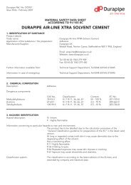
underground<br />
The systems<br />
Inspection<br />
chamber lid<br />
UCL3<br />
Gully hopper<br />
UG47<br />
Bottle gully<br />
UG50<br />
Bottle gully<br />
raising piece<br />
UG52<br />
45º short<br />
radius bend<br />
UB45<br />
Compact<br />
gully<br />
UG40<br />
45º short<br />
radius bend<br />
UB45<br />
Chamber lid<br />
& cover<br />
UCL35/UCL35PP<br />
Inspection<br />
chamber riser<br />
UCR2<br />
Pipe<br />
UP406<br />
P trap gully<br />
UG42<br />
Inspection<br />
chamber base<br />
UCC3/UCC5<br />
Pipe<br />
UP406<br />
45º short<br />
radius bend<br />
UB45<br />
Long radius<br />
bend<br />
UBL488<br />
Pipe<br />
UP406<br />
Coupling<br />
UE407<br />
Inspection chamber<br />
UCC7<br />
Straight channel<br />
UCC4<br />
Slip coupling<br />
UE405<br />
45º short radius bend<br />
UB455R<br />
Diagram for illustrative purposes only<br />
5
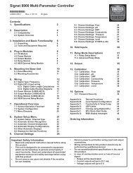
Structured wall systems<br />
Marley Quantum was developed in 1991. The objective was to maximise the structural performance of plastic pipes and to produce<br />
a pipe that was lightweight and easy to install on site. This in turn reduces the overall installation cost.<br />
<br />
Quantum is manufactured in two<br />
A red stripe, printed down the<br />
BBA 09/H146 & BBA 98/3486<br />
grades, sewer and highway, and<br />
length of the pipe, aids identification<br />
offers the following benefits over<br />
of sewer pipe.<br />
<br />
certification on Quantum Highway.<br />
WIS 4-35-01 certification on<br />
traditional materials<br />
<br />
BBA 94/2985 certification on<br />
<br />
Quantum Sewer for adoptable foul<br />
The flexibility to tolerate ground<br />
Quantum Sewer for private foul and and surface water sewers.<br />
movement without damage, whilst surface water applications.<br />
withstanding the combined effects<br />
of backfill and loading.<br />
Quantum Sewer<br />
Quantum Highway<br />
<br />
Fewer joints to reduce the likelihood Available in 150mm, 225mm &<br />
Available in 150mm, 225mm,<br />
<br />
of leaks and blockages.<br />
300mm diameters.<br />
300mm, 400mm, 500mm &<br />
600mm diameters.<br />
A high level of chemical resistance to Suitable for:<br />
the wide range of substances found in<br />
<br />
Suitable for:<br />
Adoptable foul and surface<br />
both effluent and contaminated soils. water sewers<br />
Highway surface water carrier<br />
<br />
and filter drains<br />
Private foul and surface<br />
A smooth bore gives good<br />
water applications<br />
Private surface water applications<br />
hydraulic performance.<br />
A full technical design and installation guide is available to download from marley.co.uk Technical hotline: 01622 852695<br />
6
underground<br />
The systems<br />
Inspection<br />
chamber riser<br />
UCR2<br />
Chamber lid & cover<br />
UCL35/UCL35PP<br />
Long<br />
radius bend<br />
UBL488<br />
Soil pipe<br />
SP403<br />
Rainwater<br />
pipe<br />
reducer<br />
RRM425<br />
Pipe<br />
UL406<br />
Short<br />
radius bend<br />
UB411<br />
150x110mm branch<br />
UMY10Q<br />
150mm surface water sewer<br />
ULS13/ULS16<br />
150mm foul sewer<br />
ULS13/ULS16<br />
Large diameter Quantum Highway<br />
<br />
(i)<br />
Available in 400mm , 500mm (ii) and 600mm diameters.<br />
<br />
Half slotted versions available in 400mm and 500mm diameters.<br />
<br />
Meets the requirements of The Specification for Highway works, clause 501-3.<br />
BBA 06/H122 certification.<br />
(i) 18% greater capacity than 375mm concrete<br />
(ii) over 50% greater capacity than 400mm concrete<br />
7
Key components<br />
The Marley underground<br />
drainage range offers<br />
a comprehensive range<br />
of standard fittings<br />
including bends,<br />
branches and couplings.<br />
Pictured is a selection<br />
of key components<br />
within the range.<br />
For a complete listing<br />
of the below ground<br />
range, see pages 27-31.<br />
450x110mm chamber base (UCC3D), riser<br />
(UCR3), access ring (UCLRR), lid (UCL35PP)<br />
& clip (UCC10D)<br />
450x160mm chamber base (UCC5),<br />
riser (UCR2), lid (UCL35PP) & clip (UCC10)<br />
Inspection chambers<br />
250mm and 450mm inspection<br />
chambers can be used as an alternative<br />
to traditional manholes for standard<br />
and deep inspection. See page 16-19<br />
for installation data.<br />
(see below ground price list, pages 11-16)<br />
250mm chamber (UCC7) & lid (UCL3)<br />
250mm chamber (UCC7) & lid (UCL2)<br />
A full technical design and installation guide is available to download from marley.co.uk Technical hotline: 01622 852695<br />
8
underground<br />
Key components<br />
The Marley non-return valve (USW120)<br />
The Marley non-return valve is a simple and effective way to eliminate backflow<br />
through drainage systems. The flap in the valve opens to allow discharge. In a<br />
potential flood situation, the rising water levels seal the flap shut, alleviating the<br />
risk of the water backing up into a property.<br />
The internal profile is designed to avoid any interrupted flow and provides full access<br />
for pipe cleaning or rodding. (see below ground price list, page 39)<br />
Non-return valve (USW120)<br />
Bottle gully (UG50)<br />
Ideal for new or replacement installations. Accepts waste and rainwater pipes.<br />
A fully rotating gully body allows the outlet to face the required direction<br />
of the drain connection.<br />
A removable rubber plug provides access for rodding.<br />
UG52 optional raising piece available.(see below ground price list, page 19)<br />
Bottle gully (UG50)<br />
Mechanical bend (UB47M)<br />
Adjustable bend (UB47)<br />
Mulitflex bend (MFBDO)<br />
Adjustable bends<br />
Available in 82, 110 and 160mm with<br />
a solvent weld joint or as 110mm<br />
mechanical or multiflex bends.<br />
The solvent weld bend can be adjusted<br />
by cutting the fitting at the required<br />
angle and solvent welding the two<br />
sections together.<br />
Code Angle achieved<br />
UB37 11º – 87½º<br />
UB47 21º – 90º<br />
UB67 15º – 90º<br />
The mechanical bend provides a ‘twist<br />
and lock‘ solution to achieve the<br />
desired angle of between 5º and 30º.<br />
(see below ground price list, page 7)<br />
Multiflex bends are available as<br />
socket/spigot or socket/socket (shown)<br />
and can adjusted from 0º-90º.<br />
9
Design<br />
Statutory requirements<br />
The following standards deal with drainage design:<br />
<br />
<br />
and Sewers.<br />
The design and layout of drainage and sewerage systems<br />
should comply with The Building Regulations and Water<br />
Authority Specification. Reference should also be made to the<br />
Sewers for Adoption manual.<br />
The following information is provided only as a general<br />
guide to good practice for the design of underground<br />
drainage systems. For full details please consult the relevant<br />
documents referred to above.<br />
Means of access<br />
Access is required to drainage installations for testing,<br />
inspection and removal of debris. Access to drainage allowing<br />
rodding in both directions can be provided by inspection<br />
chambers, manholes and other access fittings. Rodding eyes<br />
provide access for clearance of debris in the direction of flow<br />
only and should thus be used in conjunction with an access<br />
chamber or manhole at a point downstream.<br />
No part of the drain or sewer should be more than 50m<br />
away from a manhole. The distance between points should<br />
therefore not exceed 100m.<br />
For full guidance as to provision of access, reference should<br />
be made to BS EN 752 2008. The table below details the<br />
maximum spacing of the access points as detailed in the<br />
above standard.<br />
Access fitting To branch Shallow Manhole or deep<br />
1 2 or junction inspection chamber inspection chamber<br />
Start of external drain* 12 12 - 22 45<br />
Rodding eye 22 22 22 45 45<br />
Type 1 access fitting 150 x 100mm - - 12 22 22<br />
Type 2 access fitting 225 x 100mm - - 22 45 45<br />
Shallow inspection chamber 22 45 22 45 45<br />
Manhole or deep inspection chamber - - - 45 90<br />
* Stack or ground floor appliance<br />
Gradients <br />
litres/second size (mm) gradient<br />
Foul water drainage systems are generally designed to run at<br />
a maximum of three quarters full bore. Pipe gradients should<br />
1 82 1:80<br />
110 1:80 (b)<br />
A 110mm foul drain taking the discharge from a single stack<br />
160 1:150 (c)<br />
should be laid at a 1:40 (25mm per metre) fall. A foul drain<br />
taking the discharge from more than one stack can be laid at<br />
1:80 (12.5mm per metre).<br />
(a) Peak flow based on probability flow calculation method<br />
<br />
Gullies incorporating in foul water or combined drainage <br />
systems must have a 50mm minimum water seal.<br />
Surface water drainage systems may be designed to run full<br />
The table opposite is taken from BS EN 752 2008 and provides bore. Drains taking multiple rainwater pipes can be laid to a<br />
guidance on minimum gradients for different size drains<br />
fall of 1:100 (10mm per metre).<br />
10
underground<br />
Physical characteristics<br />
Dimensions and weights<br />
Pipe BS nominal size (mm) Min Max Wall thickness (mm) Weight kg/metre<br />
Solid wall 82 82.4 82.7 3.0 1.2<br />
110 110.0 110.3 3.2 1.7<br />
160 160.0 160.4 4.0 3.0<br />
Quantum Sewer 150 145 160 - 1.85<br />
225 226 250 - 4.20<br />
300 297 330 - 7.00<br />
Quantum Highway 150 148 160 - 1.25<br />
225 230 250 - 2.75<br />
300 302 330 - 4.65<br />
400 396 465 - 8.50<br />
500 496 580 - 13.30<br />
600 598 700 - 20.83<br />
Pipe strength<br />
<br />
Minimum short-term ring stiffness Marley solid wall 110mm 6000<br />
Marley solid wall 160mm 4000<br />
Minimum short-term ring stiffness Quantum Sewer - 8000<br />
Quantum Highway - 6000<br />
Minimum two-year ring stiffness Quantum Sewer - 4000<br />
Quantum Highway - 3000<br />
Solid wall perforated pipe<br />
110mm solid wall perforated pipe is manufactured to the<br />
dimensional requirements of BS EN 1401-1:1999. Pipe has two<br />
rows of slots that are 60mm apart and 1.75mm wide. Slot sizes<br />
as detailed in the table below.<br />
Pipe size Slot width Slot length Slotted pipe<br />
(mm) (mm) (mm) (mm 2 /m)<br />
110 1.75 24 2041<br />
120º<br />
Quantum perforated pipes<br />
Three sizes of Quantum Highway perforated pipes are<br />
available, 150, 225 and 300mm, half or fully slotted.<br />
400 and 500mm are available half slotted.<br />
Nominal Slot width Slot length Area half Area fully<br />
pipe size (mm) (mm) slotted pipe slotted pipe<br />
(mm) (mm 2 /m) (mm 2 /m)<br />
150 1.5 22 3000 6000<br />
225 1.5 38 3500 7000<br />
300 1.5 58 4000 8000<br />
400 3.5 45 18900 –<br />
500 3.5 50 19200 –<br />
60mm<br />
60º 60º<br />
45º<br />
60º<br />
The slotted cross sectional area for both solid wall and<br />
Quantum pipes exceed the perforation requirements of<br />
Half<br />
slotted pipe<br />
(150, 225 & 300mm)<br />
Half<br />
slotted pipe<br />
(400 & 500mm)<br />
Fully<br />
slotted pipe<br />
the Department of Transport ‘Specification for Highway<br />
Works’ 2001. This requires a minimum perforated area of<br />
1000mm 2 /m irrespective of pipe diameter.<br />
11
Installation data:<br />
Pipe laying<br />
The following information is based on the recommendations in BS 5955: Part 6<br />
<br />
<br />
guide to good practice in the selection of bedding and backfill materials for<br />
Marley solid wall and Quantum underground drainage systems.<br />
Excavation<br />
Trenches should not be open for<br />
extended periods in advance of pipe<br />
laying and should be backfilled as soon<br />
as possible. It is essential that the sides<br />
of the trench are adequately supported<br />
during pipe laying. Trench widths<br />
should be as narrow as is practicable<br />
but not less than the pipe diameter plus<br />
300mm to allow adequate sidefill to<br />
be placed. Deeper excavations should<br />
ideally incorporate a sub-trench in<br />
accordance with the diagram opposite.<br />
Angle of<br />
unsupported<br />
trench to be<br />
in accordance<br />
with BS EN 1610<br />
Trench width in accordance with<br />
BS EN 1610 Tables 1 & 2<br />
Sub trench<br />
excavated<br />
as shown<br />
Pipe OD<br />
+ 300mm<br />
Pipe OD+<br />
Bedding<br />
depth<br />
Granular material for bed<br />
& surround of PVCu drains<br />
and sewers<br />
Suitable imported granular material<br />
<br />
wall and Quantum Pipes for private and<br />
adoptable sewer applications is detailed<br />
in the table right:<br />
Grading complying with the<br />
requirements of BS EN 1610. Granular<br />
material also includes aggregates for<br />
concrete to BS EN 12620.<br />
Nominal pipe size<br />
100/110mm<br />
150/160mm<br />
150/225mm<br />
and over<br />
Granular material size<br />
10mm nominal single-size<br />
14 to 5mm course graded<br />
10 or 14mm nominal single-size<br />
14 to 5mm course graded<br />
10,14 or 20mm nominal single-size<br />
14 or 20 to 5mm course graded<br />
A full technical design and installation guide is available to download from marley.co.uk Technical hotline: 01622 852695<br />
12
underground<br />
Installation data<br />
Bedding & backfill<br />
Where the as-dug material is suitable*, the<br />
bottom of the trench may be trimmed to<br />
form the pipe bed and the as-dug soil used<br />
as sidefill and backfill in accordance with<br />
BS EN 1610 bedding construction type B<br />
(see drawing opposite).<br />
*Suitable material is defined as material in<br />
accordance with the recommendations of<br />
BS 5955: Part 6: 1980 Appendix A, having<br />
a maximum particle size not exceeding 20mm.<br />
300mm<br />
Pipe<br />
diameter<br />
Trench bottom trimmed<br />
to form pipe bed<br />
Selected backfill<br />
must not contain<br />
stones larger<br />
than 40mm<br />
Sidefill<br />
Where the as-dug material is unsuitable<br />
as bed and surround<br />
installation should be carried out in<br />
accordance with BS EN 1610 bedding<br />
construction type 1, as shown opposite.<br />
Trenches should be excavated to allow<br />
for the depth of bedding material.<br />
Before any pipework is installed<br />
the bedding material should be laid<br />
evenly along the bottom of the trench.<br />
300mm<br />
100mm<br />
Pipe<br />
diameter<br />
50mm or 100mm<br />
dependent on<br />
in situ soil type<br />
and condition<br />
Bed and sidefill with<br />
suitable granular material<br />
The sidefill material must be the same<br />
as the bedding material and extended<br />
to the crown of the pipe and be<br />
thoroughly compacted.<br />
Where the backfill above the pipe<br />
contains stones larger than 40mm or<br />
where the pipework is deeper than 2m<br />
in poor ground, the granular material<br />
must extend at least 100mm above<br />
the pipe crown. Alternatively, backfill<br />
material can be graded to eliminate<br />
stones exceeding 40mm and this<br />
selected material used for the first<br />
300mm above the pipe.<br />
When the pipes are to be laid<br />
in rock, compacted sand or gravel,<br />
or in very soft or wet ground requiring<br />
mechanical means of trimming,<br />
the bedding should be a minimum<br />
of 100mm.<br />
13
Installation data:<br />
Pipe laying<br />
Concrete<br />
slab<br />
polythene<br />
membrane<br />
Less than<br />
600mm<br />
backfill<br />
Pipe<br />
diameter<br />
50mm or 100mm<br />
dependent on<br />
in situ soil type<br />
and condition<br />
Paving slab<br />
75mm min<br />
granular material<br />
Bed and surround with<br />
suitable granular material<br />
100mm<br />
100mm min<br />
Pipe diameter<br />
100mm<br />
Trench dug out of<br />
compacted hardcore<br />
Bed and surround with<br />
suitable granular material<br />
Shallow domestic drains<br />
Pipes laid at depths less than 600mm and which are not<br />
under a road should, where necessary, be protected against<br />
damage by placing over them a layer of concrete, paving slabs<br />
or similar. A minimum 75mm cushioning layer of granular<br />
material must be laid between pipes and the slabs or concrete.<br />
Where drains are laid in fields, additional protection may<br />
be required from heavy vehicles and equipment. It is<br />
recommended that the installation is carried out with<br />
a concrete slab spanning the trench as shown for drains<br />
under private roads (right).<br />
Drains under solid ground floors<br />
Drains often have to be laid under buildings in order to connect<br />
sanitary pipework which has been positioned some distance<br />
from the outer walls. Where this occurs, deep hardcore within<br />
the foundation boundaries should be compacted first. The<br />
trench for the pipe should then be excavated and suitable<br />
material employed for the bedding and backfilling operation.<br />
If trenches are dug from original ground, pipes may be laid<br />
and surrounded as necessary before the top layer of hardcore<br />
is formed. Where a pipe passes through a wall or foundation<br />
of a building, a lintel or sleeve should be built-in to provide<br />
clearance around the pipe.<br />
Concrete bed & surround<br />
<br />
accommodate ground movement and other differential<br />
settlement that may occur under normal conditions.<br />
Therefore, the use of concrete bed and surround is not<br />
recommended and only under special circumstances, at very<br />
shallow cover depths or where it is necessary to safeguard<br />
foundations, should it be used. Where the use of concrete<br />
bed and surround is unavoidable, it is recommended that<br />
pipes are laid in 3 metre lengths and a compressible board<br />
is shaped to fit around each joint. Pipes should also be<br />
wrapped with polythene to prevent the ingress of cement<br />
slurry into ring seal joints.<br />
For applications in accordance with DTP requirements, please refer to the technical design and installation guide, available<br />
to download from marley.co.uk<br />
14
underground<br />
Installation data<br />
UCL2 or UCL3 lid and frame<br />
600mm max<br />
Local concrete surround<br />
UAR1 riser<br />
UAC02 chamber body<br />
UBL488<br />
long radius bend<br />
UE407<br />
coupling<br />
Bed and surround with<br />
suitable granular material<br />
Alternative 45º<br />
bend & branch<br />
250mm bottom outlet inspection chambers<br />
The 250mm bottom outlet inspection<br />
<br />
collection point for branch drains from<br />
one or more dwellings and may also<br />
serve as a rodding and testing point<br />
for the main drain. The 110mm bottom<br />
outlet ensures that discharges from the<br />
side branches are quickly transmitted<br />
to the main drain which may be<br />
situated directly under the chamber or<br />
to one side at a lower level.<br />
The bottom outlet chamber is ideal<br />
for situations where the main drain<br />
runs parallel to a building at a lower<br />
level as this allows the chamber to be<br />
positioned directly above the drain.<br />
<br />
drop arrangement with a 45° branch<br />
and bend to the main drain.<br />
Each chamber has four 110mm spigot<br />
inlets, three of which are open and<br />
the fourth can be opened for use if<br />
necessary. The UE43 plug can be used<br />
to blank off connections not required<br />
and the chamber riser UAR1 cut to<br />
accommodate invert depths of less<br />
than 600mm.<br />
<br />
and frame can be used to provide<br />
access to the chamber at ground level.<br />
17
Installation data:<br />
Inspection chambers<br />
Local concrete bed<br />
and surround to frame<br />
UCL35/UCL35PP/UCL125<br />
cover and frame<br />
UCL125 ductile iron cover<br />
and frame to BS EN 124<br />
Class B125 for use in roads<br />
Bond breaker around riser<br />
(heavy duty DPC or similiar)<br />
Surface<br />
UCR2<br />
chamber riser<br />
UCC3 110mm or<br />
UCC5 160mm base<br />
UCC10<br />
chamber<br />
riser clip<br />
Concrete<br />
surround<br />
200mm deep<br />
Chamber riser<br />
Bed and surround with<br />
suitable granular material<br />
450mm inspection chambers<br />
450mm inspection chambers may be<br />
used as an alternative to traditionally<br />
constructed manholes for invert depths<br />
of up to 1.2 metres. Intermediate<br />
depths can easily be accommodated<br />
by simply cutting a riser, between the<br />
ribbed sections, to the desired height<br />
using a fine tooth saw.<br />
<br />
a 100mm bed of suitable as-dug or<br />
granular material and care should be<br />
taken to ensure the bedding material<br />
is evenly compacted under the base<br />
so that the chamber is fully supported.<br />
During the installation stage and<br />
prior to backfilling, it is recommended<br />
that chamber riser retaining clips<br />
<br />
alignment of the chamber during the<br />
backfilling operation.<br />
Sidefill material should extend to just<br />
below ground level and the cast iron<br />
cover and frame set in a concrete plinth.<br />
Two versions of chamber base are<br />
<br />
<br />
110/160mm inlets and 160mm outlet.<br />
Both have ring seal socket connections.<br />
<br />
chamber base to a riser, or jointing riser<br />
to riser, the ring seal is always located<br />
in the first groove, as detailed opposite.<br />
To ease jointing it is recommended that<br />
silicone lubricant is used.<br />
<br />
compatible with 150mm Quantum pipe.<br />
This is achieved by removing the snap<br />
cap and seal from the chamber base<br />
and inserting Quantum pipe into the<br />
socket, with the seal located into the<br />
first corrugation of pipe.<br />
450mm inspection chambers are<br />
designed to withstand water testing<br />
in accordance with BS EN 1610.<br />
Ring seal<br />
110mm (UCC3) / 160mm (UCC5)<br />
A full technical design and installation guide is available to download from marley.co.uk Technical hotline: 01622 852695<br />
18
underground<br />
Installation data<br />
Granular material<br />
Local concrete<br />
bed & surround<br />
UCLRR<br />
UCL35PP<br />
UCR3<br />
110mm or<br />
UCC3D or UCC5<br />
160mm pipe<br />
450mm deep inspection chambers<br />
For the installation of an inspection<br />
chamber deeper than 1.2m, the<br />
regulations require the clear<br />
opening to be reduced to 350mm<br />
to prevent man entry. Inspection and<br />
maintenance should be carried out<br />
by remotely operated equipment and<br />
the maximum depth is limited to 4m.<br />
Access is only permitted when there<br />
is no other alternative.<br />
For full details please refer to the<br />
Building Regulations (England & Wales)<br />
Approved Document H – Drainage &<br />
Waste Disposal – April 2002 or Part 3 of<br />
the Building (Scotland) Regulations 2004<br />
BSEN 752 2008.<br />
The 110mm deep inspection chamber<br />
<br />
on the underside of the chamber and<br />
<br />
to the chamber base.<br />
Please note that the standard UCC3<br />
chamber base and UCR2 riser are<br />
not suitable for deep inspection<br />
applications.<br />
Featuring increased ring stiffness<br />
over our standard inspection<br />
<br />
inspection riser must be used for<br />
all deep inspection applications.<br />
Identifiable by tabs marked ‘Deep<br />
Inspection’ on the inside, each riser is<br />
480mm high (effective height 440mm)<br />
and is supplied with a 450mm ring seal.<br />
<br />
<br />
chambers for deep inspection.<br />
<br />
<br />
the required restricted opening for<br />
non-man entry.<br />
19
Installation data:<br />
Gully combinations<br />
A comprehensive range of gully components are available, allowing a wide variety of<br />
gully combinations to be assembled on site to accommodate different applications.<br />
Square or rectangular<br />
gully hoppers<br />
The square or rectangular gully hoppers<br />
UG47/UG48 and the gully inlet raising<br />
32, 40 or 50mm<br />
waste pipe<br />
UG47 rectangular<br />
gully hopper<br />
32, 40 or 50mm<br />
waste pipe<br />
UG48 square<br />
gully hopper<br />
piece UW401 all have connections for<br />
small diameter pipework above the trap<br />
SA411, 421, 420<br />
boss adaptor<br />
water level but below the gully grating.<br />
Waste pipes can be connected using<br />
standard Marley universal boss<br />
adaptors, as illustrated.<br />
The larger diameter upstands on the<br />
square or rectangular gully hoppers<br />
are designed to provide a solvent<br />
socket connection for 68mm circular<br />
110mm pipe<br />
KB1/2/3 bend<br />
110mm pipe<br />
rainwater pipes.<br />
P trap gully<br />
The double socket design of the UG42<br />
UG45 gully grating<br />
32, 40 or 50mm<br />
waste pipe<br />
P Trap Gully makes it ideal for use in<br />
restricted spaces and allows the trap to<br />
be orientated to suit the direction<br />
of the outlet pipe.<br />
SA411, 421, 420<br />
boss adaptor<br />
UW401<br />
raising piece<br />
Both the square UG48 and rectangular<br />
UG47 hoppers can be connected to the<br />
gully using a short length of 110mm<br />
pipe cut to suit ground level.<br />
110mm<br />
drain<br />
The UG45 gully grating can also be<br />
used with the UW401 raising piece to<br />
receive waste pipe connections below<br />
ground level.<br />
32, 40<br />
or 50mm<br />
waste pipe<br />
110mm drain<br />
P trap gully UG42<br />
P trap gully UG42<br />
A full technical design and installation guide is available to download from marley.co.uk Technical hotline: 01622 852695<br />
20
underground<br />
Installation data<br />
Compact gully<br />
The UG40 compact gully is simple in<br />
design, it features a unique design of<br />
baffle plate which, when removed,<br />
provides full access to the main body<br />
for cleaning and rodding purposes.<br />
32/40/50mm waste pipe or 68mm<br />
circular/65mm square downpipe<br />
UG40 gully<br />
Where a very shallow invert is required<br />
a UB45 110mm x 45° socket/spigot bend<br />
can be connected into the gully outlet.<br />
32, 40 or 50mm<br />
waste pipe<br />
The larger boss upstands on the gully<br />
accept 68mm rainwater pipe connections<br />
and the smaller upstands allow 32, 40<br />
and 50mm pipes to be connected using<br />
the appropriate boss connector.<br />
SA411, 421, 420 boss<br />
adaptor<br />
110mm<br />
socket outlet<br />
Bottle gully<br />
The UG50 bottle gully is ideal for new<br />
or replacement installations and it<br />
provides the facility for direct 110mm<br />
connections and waste pipe connections<br />
via boss adaptors.<br />
UG52<br />
raising piece<br />
rainwater pipe<br />
The fully rotating gully body allows the<br />
outlet to be orientated to suit the drain<br />
connection. A removable rubber plug<br />
provides access for cleaning.<br />
110mm<br />
solvent socket<br />
The gully raising piece UG52 allows<br />
the gully to be installed at depths up<br />
to 520mm.<br />
110mm outlet<br />
bottle gully UG50/UG50D<br />
Installation procedure for bottle gully<br />
<br />
midway between external corrugations.<br />
2. Remove sealing ring from gully frame spigot and place<br />
in first corrugation of raising piece.<br />
3. Lubricate and push fit raising piece into top of gully body.<br />
4. Gully frame spigot can then be solvent welded into top<br />
of raising piece. The gully grating may be secured to the<br />
frame if necessary with two 6 x 13mm self tapping pan<br />
head corrosion resistant screws (not supplied).<br />
21
Installation data:<br />
Making the connection<br />
Stub waste connections<br />
Isolated ground floor sanitary<br />
appliances are frequently supplied with<br />
their own 110mm drain in the form of<br />
an oversized and unventilated branch.<br />
There are two methods of connecting<br />
waste pipework direct to drain. The<br />
SRM402 reducer may be used and<br />
solvent welded onto a plain spigotupstand<br />
of pipe.<br />
With the SE41 reducer a flexible<br />
connection is provided at floor level<br />
as this fitting push fits into a ring seal<br />
socket. Standard Marley boss adaptors<br />
are used with both types of reducer.<br />
40 or 32mm pipe<br />
SA421/411 boss adaptor<br />
SRM402 reducer<br />
110mm PVCu pipe<br />
110mm PVCu to 40 or 32mm pipe<br />
40 or 32mm pipe<br />
SA421/411 boss adaptor<br />
SE41 reducer<br />
Ring seal socket<br />
110mm PVCu pipe<br />
50mm pipe<br />
SA420 boss adaptor<br />
SRM402 reducer<br />
110mm PVCu pipe<br />
110mm PVCu to 50mm pipe<br />
50mm pipe<br />
SA420 boss adaptor<br />
SE41 reducer<br />
Ring seal socket<br />
110mm PVCu pipe<br />
110mm PVCu to 40 or 32mm pipe<br />
110mm PVCu to 50mm pipe<br />
Rainwater pipe<br />
connections<br />
External rainwater pipes usually<br />
connect direct to the drain or,<br />
depending on the design of the<br />
sewerage system, via a gully trap.<br />
Where rainwater pipes connect<br />
directly to a drain and are of different<br />
sizes, a suitable reducer and adaptor<br />
fitting will be required.<br />
<br />
wall above and below ground drainage<br />
systems are the same and therefore<br />
direct connection may be achieved<br />
without an adaptor.<br />
68mm circular rainwater pipe<br />
RRM425 reducer<br />
110mm PVCu pipe<br />
110mm PVCu to 68mm circular rainwater pipe<br />
68mm circular rainwater pipe<br />
SRM325 reducer<br />
82mm PVCu pipe<br />
65mm square rainwater pipe<br />
RLE2 adaptor<br />
RRM425 reducer<br />
110mm PVCu pipe<br />
110mm PVCu to 65mm square rainwater pipe<br />
82mm circular rainwater pipe<br />
SRM304 reducer<br />
Ring seal socket<br />
110mm PVCu pipe<br />
82mm PVCu to 68mm circular rainwater pipe<br />
110mm PVCu to 82mm circular rainwater pipe<br />
A full technical design and installation guide is available to download from marley.co.uk Technical hotline: 01622 852695<br />
22
underground<br />
Installation data<br />
Connections to<br />
other materials<br />
UCA40<br />
adaptor<br />
Thin wall<br />
clay pipe<br />
2:1 sand<br />
and cement<br />
Gaskin<br />
Various adaptor fittings are available<br />
<br />
pipework to drainage systems<br />
of other materials.<br />
The UMA45 adaptor can be used to<br />
connect 160mm solid wall drainage<br />
pipes to BS EN 1401: 2000 to 150mm<br />
diameter nominal size clayware pipes<br />
as shown on page 25.<br />
110mm PVCu pipe<br />
PVCu pipe socket to thin wall clayware socket<br />
2:1 sand<br />
and cement<br />
Gaskin<br />
110mm<br />
PVCu pipe<br />
UA41 adaptor<br />
PVCu spigot to stoneware socket<br />
UCA40<br />
adaptor<br />
Stoneware<br />
socket<br />
Thin wall<br />
clay pipe<br />
Stoneware/cast<br />
iron spigot<br />
UA47<br />
adaptor<br />
UE407<br />
coupling<br />
110mm PVCu pipe<br />
PVCu socket to stoneware/cast iron spigot<br />
PVCu pipe socket to thick wall clayware socket<br />
23
Installation data:<br />
Making the connection<br />
Pipe cut between corrugations<br />
with fine tooth saw<br />
URM11 seal in<br />
first corrugation<br />
SNC6 snap cap and<br />
seal UR6IT<br />
Pipe socket or coupling<br />
150mm<br />
Quantum pipe<br />
UME15Q<br />
coupling<br />
160mm solid<br />
wall pipe<br />
Quantum seal fitted in first corrugation of pipe and handed as shown<br />
Cutting and jointing Quantum pipes<br />
Quantum pipes may be easily cut The procedure for jointing is as follows:<br />
to length on site if required using a 1. Ensure that the end of the pipe and<br />
fine tooth saw. Saw cuts should be<br />
inside the socket are free from swarf,<br />
made square to the pipe midway<br />
grit, etc.<br />
between the corrugations. It is not<br />
2. Fit seal into the first corrugation<br />
necessary to chamfer the end of the<br />
of the pipe making sure that the<br />
pipe after cutting.<br />
seal is correctly handed, as shown<br />
Unlike joints on standard solid wall<br />
above, and that it is not twisted.<br />
pipe, where the ring seal is located 3. Apply lubricant around the pipe<br />
in a housing within the socket, with<br />
seal and inside the socket.<br />
Quantum pipe the ring seal is fitted 4. Push pipe fully into the socket either<br />
around the pipe.<br />
by hand or by using a timber block<br />
and lever on the other end of the pipe.<br />
Connection to 160mm<br />
solid wall pipe<br />
All 150mm Quantum sockets<br />
have been designed for use with<br />
Quantum pipes and 160mm solid<br />
wall pipes to BS EN 1401: 2000.<br />
To adapt a Quantum fitting to<br />
accept 160mm solid wall drainage<br />
<br />
UR61T must be fitted to the end<br />
of the socket to enable a connection<br />
to be made, as shown above.<br />
Quantum couplings, bends, branches<br />
and reducers have an all socket<br />
configuration and jointing these to<br />
Quantum pipe is achieved in the same<br />
way as described above.<br />
A full technical design and installation guide is available to download from marley.co.uk Technical hotline: 01622 852695<br />
24
underground<br />
Installation data<br />
Connection to other materials<br />
Quantum pipe inserted<br />
full depth of adaptor<br />
Clayware<br />
pipe coupler<br />
Quantum pipe inserted<br />
full depth of adaptor<br />
Clayware<br />
pipe coupler<br />
Clayware<br />
pipe coupler<br />
Quantum<br />
pipe with seal<br />
fitted in 10th<br />
corrugation<br />
UMA45 adaptor with<br />
integral seal removed<br />
Thick wall<br />
clayware pipe<br />
Quantum<br />
pipe with seal<br />
fitted in 6th<br />
corrugation<br />
UMA45 adaptor with<br />
integral seal removed<br />
Thin wall<br />
clayware pipe<br />
160mm solid<br />
wall PVCu pipe<br />
UMA45 adaptor with<br />
integral seal<br />
Thick wall<br />
clayware pipe<br />
Quantum to thick<br />
wall clayware<br />
The UMA45 adaptor may be used to<br />
connect 150mm Quantum pipe to<br />
Densleeve or Hepsleeve 188mm outside<br />
diameter clayware pipe.<br />
The adaptor is designed to allow Quantum<br />
pipe to be jointed with clayware pipe<br />
using a standard clayware pipe coupler.<br />
Installation procedure<br />
1. Remove factory fitted ‘T’ seal from<br />
adaptor socket.<br />
2. Fit Quantum seal on the pipe in<br />
the 10th corrugation from the end<br />
of the pipe ensuring the seal is<br />
correctly handed.<br />
3. Lubricate the seal and inside the<br />
socket of the adaptor. Push the<br />
adaptor over the pipe, ensuring the<br />
pipe passes completely through the<br />
adaptor until the end of the pipe<br />
aligns with the end of the adaptor.<br />
4. Lubricate the adaptor spigot<br />
and push into the clayware pipe<br />
coupler up to the central register.<br />
Quantum to thin<br />
wall clayware<br />
The same adaptor can also be used<br />
to connect 150mm Quantum pipe<br />
to Hepsleeve or Supersleeve 178mm<br />
outside diameter clayware pipe. For<br />
this application the end spigot of the<br />
adaptor is first removed using a fine<br />
tooth saw. The remaining section of the<br />
adaptor is then suitable for connecting<br />
directly into a standard polypropylene<br />
clayware pipe coupler as shown above.<br />
The installation sequence for<br />
this application is similar to that<br />
previously described but the seal is<br />
fitted on the Quantum pipe in the 6th<br />
corrugation from the end of the pipe<br />
to take into account the shortened<br />
length of the adaptor.<br />
Solid wall PVCu pipe<br />
to clayware<br />
The UMA45 adaptor can also be used<br />
as supplied to connect 160mm solid<br />
<br />
as shown above.<br />
Quantum<br />
pipe<br />
Flexible<br />
coupling<br />
Flexible couplings<br />
Other pipe<br />
material<br />
The range of flexible couplings<br />
allow connections to be made<br />
between Quantum pipes and<br />
pipes of other materials.<br />
25
British & European Standards<br />
BS EN 12620: 2008, Aggregates<br />
for concrete.<br />
BS 4660 & BS EN 1401: 1999, Plastic<br />
piping systems for non-pressure<br />
underground drainage and sewerage.<br />
<br />
BS 4962: 1989, Specification for<br />
plastic pipes and fittings for use as<br />
subsoil field drains.<br />
BS 5955-6: 1980, Plastics pipework<br />
<br />
of practice for the installation of<br />
<br />
drains and sewers.<br />
BS EN 14860: 2006, Adhesives for<br />
non-pressure thermoplastic pipe systems.<br />
BS 7158: 2001, Plastic inspection<br />
chambers for drains and sewers.<br />
BS EN 124: 1994, Manhole covers<br />
and frames.<br />
BS EN 295: 1991, Vitrified clay pipes<br />
& fittings and pipe joints for drains<br />
and sewers.<br />
BS EN 681-1: 1996, Elastomeric seals.<br />
Material requirements for pipe joint seals<br />
used in water and drainage applications.<br />
Vulcanised rubber.<br />
BS EN 752: 2008, Drain & Sewer Systems<br />
outside buildings.<br />
BS EN 1295-1: 1998, Structural design of<br />
buried pipelines under various conditions<br />
of loading. General requirements.<br />
BS EN 1610: 1998<br />
Testing of Drains & Sewers.<br />
BS EN 12056-2: 2000, Gravity drainage<br />
systems inside buildings: Sanitary<br />
pipework, layout and calculation.<br />
BS EN 12056-3: 2000, Gravity drainage<br />
systems inside buildings. Roof drainage,<br />
layout and calculation.<br />
BS EN 13476-3: 2007, Plastics piping<br />
systems for non-pressure drainage<br />
and sewerage, structured wall piping<br />
systems with smooth bore and profiled<br />
external surface.<br />
BS EN ISO 9001-2: 2000, Quality<br />
management systems.<br />
BBA 88/1977, Marley Underground<br />
Drainage System.<br />
BBA 09/H146<br />
Twinwall Drainage System.<br />
BBA 94/2985, Marley Quantum Sewer<br />
<br />
and Sewerage System.<br />
BBA 98/3486, Marley Quantum<br />
<br />
Drainage System.<br />
WIS 4-08-01, Imported granular and<br />
selected as-dug bedding and sidefill<br />
materials for buried pipelines.<br />
WIS 4-35-01: 2000,<br />
Specification for Structured Wall Pipes:<br />
<br />
Certificate No. 88/1977<br />
94/2985<br />
98/3486<br />
06/H122<br />
09/H146<br />
CERTI<br />
O WATE<br />
STRY SP<br />
BS 4660 : 1999<br />
BS EN 1401 : 1999<br />
BS EN 13476-3 : 2007<br />
CATION<br />
TO WATER<br />
CERTIFIED<br />
INDUSTRY SPECIFICATION<br />
WIS 4-35-01<br />
FM30637<br />
Also available from Marley<br />
Stormwater<br />
26
Solid Wall<br />
Product information<br />
underground<br />
Description Size Code<br />
(mm)<br />
Pipe<br />
3m 110 UL403<br />
6m 110 UL406<br />
Double spigot 6m 160 UL606<br />
3m 82 UP303<br />
3m 110 UP403<br />
3m 160 UP603<br />
6m 110 UP406<br />
Push fit socket 6m 160 UP606<br />
Perforated pipe<br />
Push fit socket<br />
Straight couplings<br />
Push fit polypropylene ring seal<br />
(Supplied in U.V. resistant polythene bags)<br />
Push fit coupling<br />
6m 110 UPP406<br />
110 UE407<br />
110 UE406<br />
160 UME15C<br />
82 UE305<br />
110 UE405<br />
Push fit slip coupling 160 UME16C<br />
82 UE300<br />
110 UE400<br />
Loose pipe socket 160 UE600<br />
110 UE402<br />
Description Size Code<br />
(mm)<br />
Short radius bends<br />
Socket/spigot<br />
Socket/socket<br />
ribbed 15º 110 UB415R<br />
15º 160 UB68<br />
87½º 110 UB411<br />
87½º 160 UMB19C<br />
45º 160 UMB14C<br />
45º 110 UB455<br />
ribbed 30º<br />
110 UB4300R<br />
30º 160 UMB13C<br />
ribbed 15º<br />
110 UB4155R<br />
15º 160 UMB11C<br />
Adjustable bends<br />
11º – 87½º 82 UB37<br />
21º – 90º 110 UB47<br />
15º – 90º 160 UB67<br />
Socket should be solvent welded<br />
Multiflex bends<br />
Socket/spigot 0-90º 110 MFBS0<br />
Socket/socket 0-90º 110 MFBD0<br />
Mechanical bend<br />
Long radius bends<br />
Socket/socket<br />
5-30º 110 UB47M<br />
87½º 110 UBL488<br />
87½º 110 UBL49<br />
Description Size Code<br />
(mm)<br />
Equal branches<br />
Socket/spigot<br />
All Socket<br />
All socket<br />
Unequal branches<br />
Socket/spigot<br />
Unequal branches<br />
ribbed 110 UY401R<br />
87½º<br />
45º 110 UY466<br />
45º 160 UMY11C<br />
ribbed 110 UY466R<br />
45º<br />
87½º 110 UY400<br />
87½º 160 UMY13C<br />
ribbed 110 UY400R<br />
87½º<br />
45º 160x110 UY66<br />
87½º 160x110 UY64<br />
45º 160x110 UMY10C<br />
Triple socket<br />
Allows up to 150mm movement/settlement<br />
Socket/spigot with 900mm tail<br />
87½º 160x110 UMY12C<br />
Short radius bends<br />
87½º 82 UB31<br />
87½º 110 UB41<br />
87½º 160 UFB61<br />
45º 82 UB35<br />
45º 110 UB45<br />
45º 160 UFB65<br />
Equal branches<br />
45º 82 UY36<br />
45º 110 UY46<br />
45º 160 UY63<br />
ribbed 110 UY46R<br />
45º<br />
87½º 110 UY401<br />
All socket<br />
Access pipe<br />
Socket/spigot<br />
110 UF42<br />
30º ribbed 110 UB430R<br />
87½º 160 UY601<br />
30º 160 UB69<br />
To BS EN 1401 UD SDR41, BS 4660: 2000 or BBA 88/1977 as appropriate.<br />
27
Solid Wall<br />
Product information<br />
Description Size Code<br />
(mm)<br />
Description Size Code<br />
(mm)<br />
Description Size Code<br />
(mm)<br />
Rear access bend<br />
87½º 110 UB42<br />
Deep inspection chamber<br />
110 UCC3D<br />
Spare blanking plug<br />
110 UCP1<br />
160 UCP2<br />
Socket/spigot<br />
Access branches<br />
45º equal 110 UY471<br />
Left hand<br />
All socket connections<br />
Deep inspection chamber riser<br />
110 UCR3<br />
Spare ring seal<br />
450 SR450<br />
250mm level invert inspection chamber<br />
110 UCC7<br />
45º equal 110 UY472<br />
Right hand<br />
Socket/spigot<br />
Rodding point<br />
45º 110 URP1<br />
45º 160 URP2C<br />
Socketed with black cover<br />
Access cap<br />
Pressure plug<br />
Socket plug<br />
1 boss upstand<br />
110 UE42<br />
160 UE62<br />
110 UE43<br />
160 UE64<br />
110 SE41<br />
450mm inspection chamber base<br />
110 UCC3<br />
max invert depth 1.2m<br />
160 UCC5<br />
max invert depth 4m (when used with UCR3) all socket<br />
connections<br />
Chamber riser<br />
110 UCR2<br />
400mm high<br />
Includes one 450mm seal<br />
For use with UCC3D or UCC5 when invert depth is greater<br />
than 1.2m. Max invert depth 4m<br />
480mm high. Includes one 450mm seal<br />
Reduced access ring<br />
110 UCLRR<br />
Provides 350mm restricted opening.<br />
Snap lock connection to the frame of the UCL35PP<br />
Inspection cover & frame<br />
450 UCL35<br />
Cast iron – 3.5 tonnes (class A15)<br />
450 UCL35PP<br />
Polypropylene for non-trafficked applications only<br />
50 UCL125<br />
Ductile iron – 12.5 tonnes (class B125)<br />
Chamber riser clip<br />
Deep inspection chamber riser clip<br />
Inspection chamber inserts<br />
UCC10<br />
UCC10D<br />
160 UCB1<br />
Left hand<br />
160 UCB2<br />
Right hand<br />
For use with UCC5 Inspection chamber<br />
– Max invert, depth 600mm<br />
All socket connections<br />
250mm double branch chamber base<br />
110 UAC44<br />
45º equal connectors<br />
Includes two socket plugs<br />
250mm bottom outlet chamber body<br />
110 UAC02<br />
90º equal connections<br />
4 x 110mm upstands, 3 open<br />
Chamber riser<br />
250 UAR1<br />
375mm long<br />
For use with<br />
UAC02 & UAC44<br />
Lifting handle<br />
For use with UAC44 110 KP204W<br />
Inspection cover & frame<br />
250 UCL2<br />
PVCu (Class A15)<br />
Spare ring seal<br />
250 SR250<br />
Optional for UCL2 PVCu lid<br />
Inspection cover & frame<br />
300 UCL3<br />
PVCu (Class A15)<br />
To BS EN 1401 UD SDR41, BS 4660: 2000 or BBA 88/1977 as appropriate.<br />
28
underground<br />
Description Size Code<br />
(mm)<br />
Straight double spigot open channel<br />
1.5m long, with 600mm opening<br />
Long radius channel bend<br />
Socket/socket<br />
Slipper bends<br />
110 UCC4<br />
87½º 110 UCB48L<br />
45° 110 USB41<br />
Description Size Code<br />
(mm)<br />
Bottle gully<br />
Bottle gully 110 UG50<br />
Bottle gully with back inlet open<br />
Bottle gully with sealed access lid<br />
A15 loading<br />
Spare bottle gully grid<br />
110 UG50D<br />
110 UG50SA<br />
Grid 110 UG51<br />
Sealed access grid 110 UG51SA<br />
Description Size Code<br />
(mm)<br />
Grating components<br />
Grating assembly 110 UG45<br />
Spare grating<br />
suits UG40, 45, 47 & 48 110 UG46<br />
Spare back plate<br />
suits UG40 & UG47 110 UG49<br />
Inlet raising pieces<br />
2 x 82mm upstands 110 UWS43<br />
4 boss upstands 110 UW401<br />
Left hand<br />
45° 110 USB42<br />
Right hand<br />
Level invert reducers<br />
Spigot/socket<br />
110-82 URM304<br />
For use with UG50 bottle gully<br />
Bottle gully raising grid<br />
Compact gully<br />
110 UG52<br />
110 UG40<br />
Yard gully<br />
634mm deep x 110 UYG40<br />
315mm diameter<br />
Grating and frame<br />
110 UYG42<br />
BS EN 124 class B125<br />
12.5 tonnes<br />
Spigot/socket<br />
Eccentric reducers<br />
Solvent socket to boss upstand<br />
Solvent socket to 68mm downpipe<br />
160-110 URM604<br />
82-50 SRM30<br />
82-68 SRM325<br />
110-50 SRM402<br />
45° outlet<br />
‘P’ trap gully<br />
81½º outlet<br />
Gully trap base<br />
45° outlet<br />
Rectangular hopper<br />
110 UG42<br />
110 UG44<br />
Adaptors<br />
PVCu pipe socket to salt 110 UA41<br />
glazed/pitch fibre pipe socket<br />
Salt glazed/cast iron spigot 110 UA47<br />
to PVCu spigot<br />
Socket/socket to suit thin 110 UCA40<br />
wall clayware spigot pipe<br />
Socket/socket to suit thick 110 UCA41<br />
wall clayware pipe<br />
Solvent socket to boss upstand<br />
110 UG47<br />
Rainwater to 110mm drain 110 UA42<br />
110-68 URM425<br />
Solvent socket to 68mm downpipe<br />
Concentric reducer<br />
2 boss upstands<br />
Square hopper<br />
110 UG48<br />
Universal waste to 110 UA43<br />
110mm drain<br />
110-50 SE41<br />
Spigot to boss upstand<br />
2 boss upstands<br />
To BS EN 1401 UD SDR41, BS 4660: 2000 or BBA 88/1977 as appropriate.<br />
29
Quantum Structured Wall<br />
Product information<br />
Description Size Code<br />
(mm)<br />
Description Size Code<br />
(mm)<br />
Description Size Code<br />
(mm)<br />
Quantum sewer pipe<br />
Bends<br />
Unequal branch<br />
3m 150 ULS13<br />
3m 225 ULS23<br />
3m 300 ULS33<br />
6m 150 ULS16<br />
Double socket<br />
87½º 150 UMB19Q<br />
87½º 225 UMB29<br />
87½º 300 UMB39<br />
45º 225x100 UMY20<br />
45º 300x150 UMY31<br />
Double spigot<br />
45º 150 UMB14Q<br />
3m 150 UPS13<br />
3m 225 UPS23<br />
3m 300 UPS33<br />
Double socket<br />
45º 225 UMB24<br />
45º 300 UMB34<br />
45º 225x150 UMY21<br />
6m 150 UPS16<br />
6m 225 UPS26<br />
30º 150 UMB13Q<br />
30º 225 UMB23<br />
45º 300x225 UMY32<br />
6m 300 UPS36<br />
30º 300 UMB33<br />
Pipe with coupling and seals<br />
Quantum highway pipe<br />
6m 150 UPH16<br />
6m 225 UPH26<br />
6m 300 UPH36<br />
Push-fit socket<br />
6m 150 USH16<br />
6m 225 USH26<br />
Double socket<br />
Double socket<br />
Equal branch<br />
15º 150 UMB11Q<br />
15º 225 UMB21<br />
15º 300 UMB31<br />
45º 150 UMY11Q<br />
45º 225 UMY22<br />
45º 300 UMY33<br />
Plugs<br />
45º 300x110 UMY30<br />
150 UMJ11<br />
6m 300 USH36<br />
Half slotted socket<br />
All socket<br />
Socket Plug<br />
Order seals if required<br />
87½º 150 UMY13Q<br />
150 UMK11<br />
6m 150 UHH16<br />
6m 225 UHH26<br />
6m 300 UHH36<br />
End Cap<br />
225 UMK21<br />
300 UMK31<br />
Fully slotted socket<br />
Order seals if required<br />
All socket<br />
Unequal branch<br />
Level invert reducer<br />
225x50<br />
UML21<br />
Couplings<br />
45º 150x110 UMY10Q<br />
300x225 UML32<br />
150 UME15Q<br />
225 UME25<br />
Straight<br />
300 UME35<br />
150 UME16Q<br />
87½º 150x110 UMY12Q<br />
Adaptors<br />
150 UMA45<br />
225 UME26<br />
300 UME36<br />
Quantum/solid wall<br />
Slip<br />
PVC to clayware pipe coupler<br />
To BBA 94/2985, 09/H146 or 98/3486 as appropriate. Quantum Sewer pipe to WLS 4-35-01.<br />
30
underground<br />
Description Size Code<br />
(mm)<br />
Description Size Code<br />
(mm)<br />
Description Size Code<br />
(mm)<br />
Adaptors<br />
150 UMA17<br />
Polyethylene gully pot liner<br />
(500mm diameter)<br />
Coupling<br />
600 UME65Q<br />
Quantum socket to solid wall spigot<br />
Flexible coupling<br />
Flexible gully connecting pipe<br />
150 UMD17<br />
225 UMD27<br />
300 UMD37<br />
50m length 150 UMA44<br />
90 litres (760mm deep) 150 UMA43<br />
112 litres (920mm deep) 150 UMA49<br />
Rodding point<br />
45º 150 URP2Q<br />
Straight<br />
Bend<br />
Double socket<br />
45º 400 UMB44<br />
45º 500 UMB54<br />
45º 600 UMB64<br />
Aluminium cover<br />
Lubricant<br />
1kg<br />
UMA41<br />
Unequal branch<br />
45º 400x225 UMY42<br />
45º 500x225 UMY52<br />
Pipe seals<br />
Quantum pipe seal (1) 150 UMR11<br />
225 UMR21<br />
300 UMR31<br />
Seal to convert 150 UR61T<br />
Quantum 150mm<br />
sockets for use with<br />
BS EN 1401 pipe<br />
Seal cap to convert 150 SNC6<br />
Quantum 150mm<br />
sockets for use with<br />
BS EN 1401 pipe<br />
Quantum seal pack<br />
2 x UMR21 + 1 x UMR11 225 UMR24<br />
2 x UMR31 + 1 x UMR11 300 UMR34<br />
2 x UMR31 + 1 x UMR21 300 UMR35<br />
Quantum highway pipe<br />
6m 400 UPH46<br />
6m 500 UPH56<br />
6m 600 UPH66<br />
Push-fit socket<br />
Quantum highway pipe<br />
6m 400 USH46<br />
6m 500 USH56<br />
Half slotted socket<br />
Coupling<br />
400 UME45Q<br />
500 UME55Q<br />
Pipe seals<br />
45º 400x150 UMY41<br />
45º 500x150 UMY51<br />
45º 600x150 UMY61<br />
Quantum pipe seal (1) 400 UMR41<br />
500 UMR51<br />
600 UMR61<br />
Seals are supplied separately and<br />
should be ordered in addition to<br />
pipe and fittings.<br />
Branches are spigot ended and<br />
need to be used in conjunction<br />
with couplings and seals.<br />
To BBA 94/2985, 09/H146, 98/3486 or 06/H122 as appropriate.<br />
31
Head Office<br />
Lenham, Maidstone, Kent ME17 2DE<br />
Telephone: 01622 858888<br />
Fax: 01622 858725<br />
marley.co.uk<br />
Scotland<br />
Birkenshaw Industrial Estate<br />
Uddingston, Glasgow G71 5PA<br />
Telephone: 01698 815231<br />
Fax: 01698 810307<br />
Export Division<br />
Lenham, Maidstone<br />
Kent ME17 2DE England<br />
Telephone: +44 (0)1622 858888<br />
Fax: +44 (0)1622 850778<br />
Further information<br />
For Technical advice<br />
please call 01622 852695<br />
For general enquiries and details of your<br />
nearest stockist please call the customer<br />
services department on 01622 852585<br />
email: marketing@marleyext.com