CATALOGUE
GENERAL CATALOGUE - Unimec
GENERAL CATALOGUE - Unimec
- No tags were found...

Create successful ePaper yourself
Turn your PDF publications into a flip-book with our unique Google optimized e-Paper software.
The ambient factor f a<br />
By means of the following table it is possible to calculate the f a factor according to the operation conditions.<br />
Type of load Daily working hours [h] 3 8 24<br />
Light shocks, few insertions, regular movements 0,8 1 1,2<br />
Medium shocks, frequent insertions, regular movements 1 1,2 1,5<br />
High shocks, many insertions, irregular movements 1,2 1,8 2,4<br />
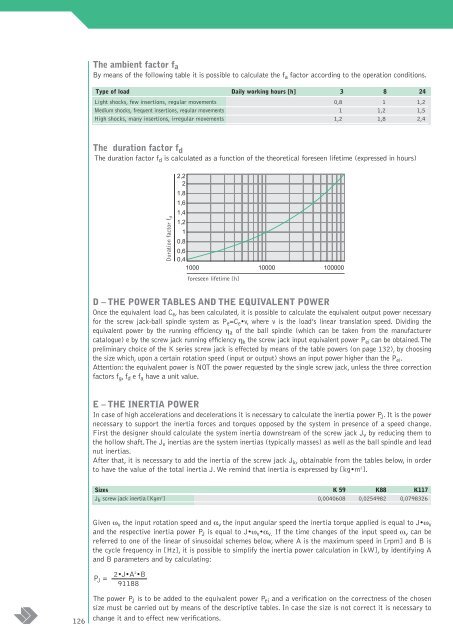
The duration factor f d<br />
The duration factor f d is calculated as a function of the theoretical foreseen lifetime (expressed in hours)<br />
Duration factor f d<br />
2,2<br />
2<br />
1,8<br />
1,6<br />
1,4<br />
1,2<br />
1<br />
0,8<br />
0,6<br />
0,4<br />
1000 10000 100000<br />
foreseen lifetime [h]<br />
D – THE POWER TABLES AND THE EQUIVALENT POWER<br />
Once the equivalent load C e , has been calculated, it is possible to calculate the equivalent output power necessary<br />
for the screw jack-ball spindle system as P e =C e •v, where v is the load’s linear translation speed. Dividing the<br />
equivalent power by the running efficiency η a of the ball spindle (which can be taken from the manufacturer<br />
catalogue) e by the screw jack running efficiency η k the screw jack input equivalent power P ei can be obtained.The<br />
preliminary choice of the K series screw jack is effected by means of the table powers (on page 132), by choosing<br />
the size which, upon a certain rotation speed (input or output) shows an input power higher than the P ei .<br />
Attention: the equivalent power is NOT the power requested by the single screw jack, unless the three correction<br />
factors f g ,f d e f a have a unit value.<br />
E – THE INERTIA POWER<br />
In case of high accelerations and decelerations it is necessary to calculate the inertia power P J . It is the power<br />
necessary to support the inertia forces and torques opposed by the system in presence of a speed change.<br />
First the designer should calculate the system inertia downstream of the screw jack J v by reducing them to<br />
the hollow shaft.The J v inertias are the system inertias (typically masses) as well as the ball spindle and lead<br />
nut inertias.<br />
After that, it is necessary to add the inertia of the screw jack J k , obtainable from the tables below, in order<br />
to have the value of the total inertia J. We remind that inertia is expressed by [kg•m 2 ].<br />
Sizes K 59 K88 K117<br />
J k screw jack inertia [Kgm 2 ] 0,0040608 0,0254982 0,0798326<br />
Given ω v the input rotation speed and α v the input angular speed the inertia torque applied is equal to J•ω v<br />
and the respective inertia power P J is equal to J•ω v •α v. If the time changes of the input speed ω v can be<br />
referred to one of the linear of sinusoidal schemes below, where A is the maximum speed in [rpm] and B is<br />
the cycle frequency in [Hz], it is possible to simplify the inertia power calculation in [kW], by identifying A<br />
and B parameters and by calculating:<br />
P J =<br />
2•J•A 2 •B<br />
91188<br />
126<br />
The power P J is to be added to the equivalent power P ei and a verification on the correctness of the chosen<br />
size must be carried out by means of the descriptive tables. In case the size is not correct it is necessary to<br />
change it and to effect new verifications.