CATALOGUE
GENERAL CATALOGUE - Unimec
GENERAL CATALOGUE - Unimec
- No tags were found...

Create successful ePaper yourself
Turn your PDF publications into a flip-book with our unique Google optimized e-Paper software.
A – The application data<br />
For a right dimensioning of the bevel gearboxes it is necessary to identify the application data: POWER,<br />
TORQUE, AND REVOLUTION SPEED = a P power [kW] is defined as the product between the torque M t<br />
[daNm] and the revolution speed ω [rpm].The input power (P i ) is equal to the sum of the output power (P u )<br />
and the power dissipated into heat (P d ).The ratio of output power and input power is called running efficiency<br />
η of the transmission.<br />
The slow shaft revolution spee ω L is equal to the fast shaft revolution ω v multiplied by the reduction ratio i<br />
(meant as a fraction). Some useful formulas that link the above variables are shown below<br />
P v =<br />
M tv •ω v<br />
955<br />
P L =<br />
M tL •ω L<br />
955<br />
ω L = ω v •i<br />
P<br />
P u<br />
i = P u +P d =<br />
η<br />
AMBIENT VARIABLES = these values identify the environment and the operating conditions of the bevel<br />
gearbox. Among them: temperature, oxidizing and corrosive factors, working and non-working periods, vibrations,<br />
maintenance and cleaning, insertion frequency, expected lifetime etc.<br />
MOUNTING SCHEMES = There are several ways of transferring movement by means of bevel gearboxes. A<br />
clear idea on the mounting scheme allows to correctly identify the power flow of the same.<br />
B- THE REAL CONTINUOUS POWER<br />
The first step for the dimensioning of a bevel gearbox is to calculate the real continuous power. By means of<br />
the formulas indicated at point A the user must calculate the input power P i according to the scheme<br />
parameters.Two calculation criteria can be adopted: using the average parameters calculated on a significant<br />
period or adopting the maximum parameters. It is obvious that the second method (the worst case) is much<br />
more protective with respect to the average one and it should be used in case you need certainty and<br />
reliability.<br />
C – THE POWER TABLES AND THE EQUIVALENT POWER<br />
All the values listed in the catalogue refer to a use in standard conditions, that is with a 20° temperature and<br />
under a regular running, without shocks for 8 daily working hours.The use under those conditions provides a<br />
lifetime of 10.000 hours. For different application conditions the equivalent power P e should be calculated:<br />
it is the power which would be applied in standard conditions in order to have the same thermal exchange<br />
and wear effects, which the real load achieves in the real conditions of use.<br />
It is therefore advisable to calculate the equivalent load according to the following formula:<br />
P e = P i •f g •f a •f d<br />
It should be remarked that the equivalent power is not the power requested by the bevel gearbox: it is and<br />
indicator which helps in choosing the most suitable size in order to have higher reliability requisites. The<br />
power requested by the application is the input power P i .<br />
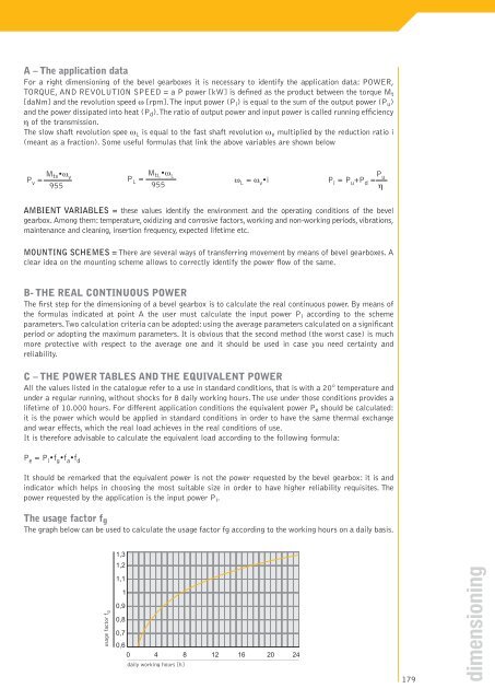
The usage factor f g<br />
The graph below can be used to calculate the usage factor fg according to the working hours on a daily basis.<br />
1,3<br />
1,2<br />
usage factor f g<br />
1,1<br />
1<br />
0,9<br />
0,8<br />
0,7<br />
0,6<br />
0 4 8 12 16 20 24<br />
daily working hours [h]<br />
179<br />
dimensioning