CATALOGUE
GENERAL CATALOGUE - Unimec
GENERAL CATALOGUE - Unimec
- No tags were found...

You also want an ePaper? Increase the reach of your titles
YUMPU automatically turns print PDFs into web optimized ePapers that Google loves.
SU Lead nut for monitored wear control<br />
In many applications it is necessary to steady check the wear conditions of the main support nut, be it the<br />
worm wheel or the lead nut.<br />
The lead nut for monitored wear control has been designed for that purpose: it couples to the support nut<br />
through an insert and follows its movement.<br />
When the main support nut starts wearing out, the axial backlash in the threaded spindle coupling is<br />
increased, and, under load, the safety lead nut get closer to the support nut.<br />
This phenomenon means a reduction of the L or L1 quote (according to the model). When this reduction<br />
reaches the X value indicated in the table below, the support nut and the lead nut MUST be replaced,<br />
otherwise the wear phenomena could cause a collapse of the load.<br />
THE LEAD NUT FOR MONITORED WEAR CONTROL IS NOT A SAFETY LEAD NUT AND IT IS<br />
THEREFORE NOT DESIGNED FOR SUPPORTING THE LOAD. After mounting, it is therefore necessary<br />
to periodically measure the L or L1 quote, in order to check the wear conditions of the components. A lead<br />
nut for monitored wear control only works in one way: either it monitors the wear conditions under a traction<br />
load or it controls the wear condition under a compression load.<br />
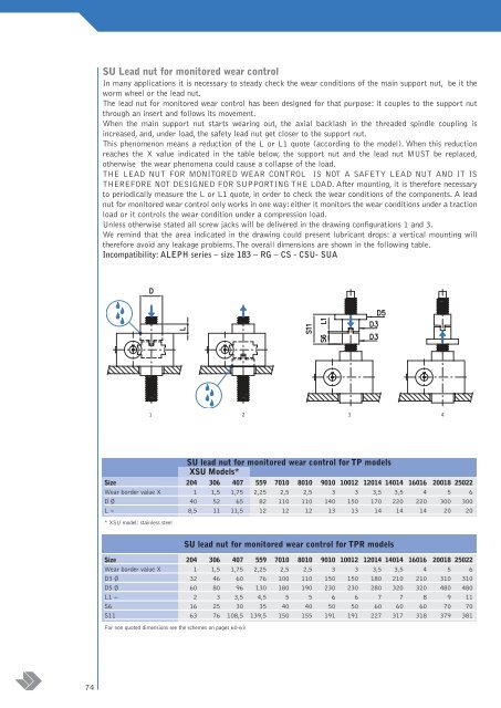
Unless otherwise stated all screw jacks will be delivered in the drawing configurations 1 and 3.<br />
We remind that the area indicated in the drawing could present lubricant drops: a vertical mounting will<br />
therefore avoid any leakage problems.The overall dimensions are shown in the following table.<br />
Incompatibility: ALEPH series – size 183 – RG – CS - CSU- SUA<br />
1 2 3 4<br />
SU lead nut for monitored wear control for TP models<br />
XSU Models*<br />
Size 204 306 407 559 7010 8010 9010 10012 12014 14014 16016 20018 25022<br />
Wear border value X 1 1,5 1,75 2,25 2,5 2,5 3 3 3,5 3,5 4 5 6<br />
D Ø 40 52 65 82 110 110 140 150 170 220 220 300 300<br />
L ~ 8,5 11 11,5 12 12 12 13 13 14 14 14 20 20<br />
* XSU model: stainless steel<br />
SU lead nut for monitored wear control for TPR models<br />
Size 204 306 407 559 7010 8010 9010 10012 12014 14014 16016 20018 25022<br />
Wear border value X 1 1,5 1,75 2,25 2,5 2,5 3 3 3,5 3,5 4 5 6<br />
D3 Ø 32 46 60 76 100 110 150 150 180 210 210 310 310<br />
D5 Ø 60 80 96 130 180 190 230 230 280 320 320 480 480<br />
L1 ~ 2 3 3,5 4,5 5 5 6 6 7 7 8 9 11<br />
S6 16 25 30 35 40 40 50 50 60 60 60 70 70<br />
S11 63 76 108,5 139,5 150 155 191 191 227 317 318 379 381<br />
For non quoted dimensions see the schemes on pages 60-63<br />
74