- Page 1 and 2:
GENERAL CATALOGUE
- Page 3 and 4:
18 Trapezoidal screw jacks 86 Aleph
- Page 5 and 6:
BEVEL GEAR BOXES 156 Production lin
- Page 8 and 9:
In times of recent globalisation UN
- Page 10:
The two activities which are the co
- Page 14 and 15:
You maybe did not know that many ac
- Page 16:
If the production is proud of its
- Page 20 and 21:
60 TP Threaded spindle model with t
- Page 22 and 23:
72 CS TP model screw jacks with saf
- Page 24 and 25:
79 FP TP model screw jacks with pas
- Page 26 and 27:
Models TP MODEL: threaded spindle w
- Page 28 and 29:
LOAD ANALYSIS AND COMPOSITION Choos
- Page 30 and 31:
BACKLASH Backlash on the worm screw
- Page 32 and 33:
LUBRICATION Inner lubrication The l
- Page 34 and 35:
INSTALLATION AND MAINTENANCE Instal
- Page 36 and 37:
TP MODEL 21 1 2 3 4 5 5.1 6 8 8.1 9
- Page 38 and 39:
DIMENSIONING OF THE SCREW JACK For
- Page 40 and 41:
C - THE EQUIVALENT LOAD All the val
- Page 42 and 43:
E - BUCKLING In case of compression
- Page 44 and 45:
F - THE LATERAL LOAD As stated in t
- Page 46 and 47:
Size 183 Ratio 1/5 Load [daN] 500 4
- Page 48 and 49:
Size 306 Ratio 1/5 Load [daN] 2500
- Page 50 and 51:
Size 559 Ratio 1/5 Load [daN] 10000
- Page 52 and 53:
Size 8010 Ratio 1/5 Load [daN] 2500
- Page 54 and 55:
Size 10012 Ratio 1/10 Load [daN] 40
- Page 56 and 57:
Size 14014 Ratio 1/12 Load [daN] 80
- Page 58 and 59:
Size 20018 Ratio 1/12 Load [daN] 15
- Page 60 and 61:
Series construction models B model
- Page 62 and 63:
Series construction models stroke t
- Page 64 and 65:
Series construction models MBD mode
- Page 66 and 67:
PR rigid protection The application
- Page 68 and 69:
PE elastic protection The purpose o
- Page 70 and 71:
PRA double guide anti-rotation As a
- Page 72 and 73:
CS Safety lead nut for monitored we
- Page 74 and 75:
SU Lead nut for monitored wear cont
- Page 76 and 77:
RG Anti axial backlash lead nut As
- Page 78 and 79:
SP Additional mounting plates If fo
- Page 80 and 81:
PO Rigid rocking protection When it
- Page 82 and 83:
AM Over-size spindle stroke stroke
- Page 84 and 85:
MOUNTING SCHEMES Scheme 1 B5 form m
- Page 86 and 87:
aleph New market demands, the growt
- Page 88 and 89:
aleph Models TP MODEL: threaded spi
- Page 90 and 91:
HANDLING Manual operation The Aleph
- Page 92 and 93:
TP MODEL 21 1 Casing (half-shell) 4
- Page 94 and 95:
DIMENSIONING OF THE SCREW JACK For
- Page 96 and 97:
The temperature factor f t By means
- Page 98 and 99:
D - THE POWER TABLES AND THE EQUIVA
- Page 100 and 101:
E - BUCKLING In case of compression
- Page 102 and 103: In order to complete the calculatio
- Page 104 and 105: Series construction models B model
- Page 106 and 107: PR rigid protection The application
- Page 108 and 109: PRF stroke control In order to meet
- Page 110: The ball screw jacks proposed in th
- Page 113 and 114: CK Screw jack suitable for applicat
- Page 115 and 116: CR K model screw jack with worm whe
- Page 117 and 118: GLOSSARY A = maximum angular speed
- Page 119 and 120: LUBRICATION Inner lubrication The l
- Page 121 and 122: Routine maintenance Screw jacks mus
- Page 123 and 124: MK MODEL 13 8 6 2 Casing Cover Holl
- Page 125 and 126: A - THE APPLICATION DATA For a righ
- Page 127 and 128: Rotation speed [rpm] time [s] Rotat
- Page 129 and 130: I - LOAD STRENGHT As a last step in
- Page 131 and 132: Static Load C [N] Ball screw type S
- Page 133 and 134: BALL LEAD NUTS MOUNTING KT Models M
- Page 135 and 136: d) FLANGED LEAD NUT WITH DIAMETER =
- Page 137 and 138: f) FLANGED LEAD NUT WITH DIAMETER >
- Page 139 and 140: Series construction models B model
- Page 141 and 142: GR rotating guide The rotating guid
- Page 143 and 144: GSS upper static guide The upper st
- Page 145 and 146: PRO oil bath rigid protection The a
- Page 147 and 148: PRF stroke control In order to meet
- Page 149 and 150: CR rotation control In some cases i
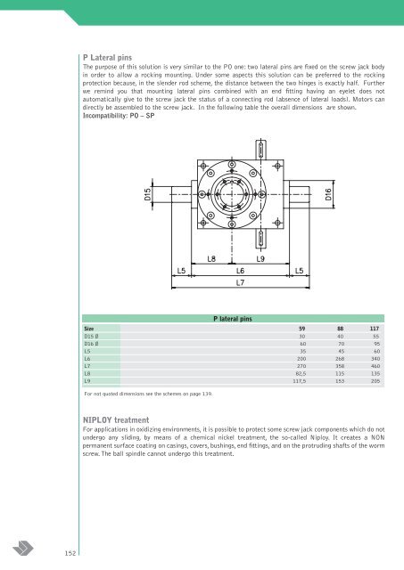
- Page 151: PO rigid rocking protection When it
- Page 155 and 156: Scheme 5 Scheme 6 Scheme 7 155 moun
- Page 157 and 158: 157 capitolo
- Page 159 and 160: RM Bevel gearboxes with fast double
- Page 161 and 162: MRZ Two hub shafts bevel gearboxes
- Page 163 and 164: GLOSSARY A = maximum input angular
- Page 165 and 166: RC RR RB RA RS RP Size 54 86 110 13
- Page 167 and 168: RC RR RB RA RS RP Size 54 86 110 13
- Page 169 and 170: HANDLING All bevel gearboxes can be
- Page 171 and 172: 4000 Input revolution shaft [rpm] 3
- Page 173 and 174: ORDERING CODES RC 86 C1 1/1 model s
- Page 175 and 176: RIS Model 17 22 18 2 8 14 23 12 13
- Page 177 and 178: RH Model 23 22 21 38 17 10 18 3 2 8
- Page 179 and 180: A - The application data For a righ
- Page 181 and 182: D - THE INERTIA POWER In case of im
- Page 183 and 184: E - LUBRICATION After a first dimen
- Page 185 and 186: RC RR RB RA RS RP RX RZ RIS Ratio 1
- Page 187 and 188: RC RR RB RA RS RP RX RZ Ratio 1/4 5
- Page 189 and 190: NIPLOY treatment For applications i
- Page 191 and 192: Base mounting schemes ratio: 1/1 C1
- Page 193 and 194: Base mounting schemes ratio: 1/1 C1
- Page 195 and 196: Base mounting schemes ratio: 1/1 S1
- Page 197 and 198: Base mounting schemes ratio: 1/1 S3
- Page 199 and 200: Base mounting schemes ratio: 1/1 -
- Page 201 and 202: atio: 1/4,5 - 1/6 - 1/9 - 1/12 High
- Page 203 and 204:
atio: 1/4,5 - 1/6 - 1/9 - 1/12 High
- Page 205 and 206:
atio: 1/2 - 1/3 - 1/4,5 Inverted be
- Page 207 and 208:
atio: 1/2 - 1/3 - 1/4,5 Inverted ge
- Page 209 and 210:
Base mounting schemes ratio: 1/1 MC
- Page 211 and 212:
Base mounting schemes ratio: 1/1 MS
- Page 213 and 214:
Base mounting schemes ratio: 1/1 MS
- Page 215 and 216:
215 high reduction motor gearboxes
- Page 217 and 218:
S11 S12 S13 S15 RS - RP m2 m2 m2 m2
- Page 219 and 220:
219 capitolo
- Page 221 and 222:
Acetylene Vinegar Vinegar (vapours)
- Page 224 and 225:
248 F One stage speed modulation ge
- Page 226 and 227:
Casings The speed modulation gearbo
- Page 228 and 229:
LOAD ANALYSIS AND COMPOSITION The a
- Page 230 and 231:
BACKLASHES The gears connection pre
- Page 232 and 233:
LUBRICATION The lubrication of the
- Page 234 and 235:
INSTALLATION AND MAINTENANCE Instal
- Page 236 and 237:
DIMENSIONING OF THE SPEED MODULATIO
- Page 238 and 239:
The usage factor f g The graph belo
- Page 240 and 241:
Given ω v the fast revolution spee
- Page 242 and 243:
F Model Ratio 1/3 Size 32 42 55 Fas
- Page 244 and 245:
RC/F-RS/F Model Ratio 1/2 Size 32 4
- Page 246 and 247:
RC/FP-RS/FP-RIS/FP Model Ratio 1/3
- Page 248 and 249:
Series construction models model 1
- Page 250 and 251:
Series construction models model 7
- Page 252 and 253:
Series construction models model 11
- Page 254 and 255:
M Models M Models Size IEC Flange D
- Page 256 and 257:
42 43 44 45 46 47 48 49 50 51 52 53
- Page 258 and 259:
NIPLOY treatment For applications i
- Page 260:
To complete its range of production
- Page 263 and 264:
UMM couplings UM6M UM7M UM8M UM9M U
- Page 265 and 266:
265 units of measure
- Page 267 and 268:
This catalogue cancels and replaces
- Page 269 and 270:
SOLAR SERIES
- Page 271 and 272:
La production d’énergies propres
- Page 273 and 274:
SOLAR model SOLAR 1 SOLAR 2 SOLAR 3