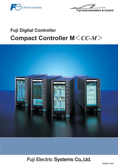
Compact Controller MCC-M
ECNO:1127a
ECNO:1127a

You also want an ePaper? Increase the reach of your titles
YUMPU automatically turns print PDFs into web optimized ePapers that Google loves.
Fuji Instrumentation & Control<br />
Fuji Digital <strong>Controller</strong><br />
<strong>Compact</strong> <strong>Controller</strong> <strong>MCC</strong>-M<br />
ECNO:1127a
Open network<br />
High-level communications using Modbus protocol allows the CC-M to be connected to a PLC or PC. OPTO22<br />
I/O modules can be connected to each CC-M using low-level communications.<br />
CC-M<br />
PLC<br />
Other System<br />
RS-485/Modbus<br />
CC-M<br />
Mainframe<br />
input/<br />
output<br />
PV PV PV<br />
OPTO-22<br />
MV<br />
MV<br />
MV<br />
Extended<br />
input/output<br />
A variety of control functions<br />
¡Single loop control<br />
¡Multi-loop control<br />
¡Cascade control<br />
¡Ratio control<br />
¡Program control<br />
¡Multi-point input selection control<br />
¡Various advanced control<br />
¡Sequence logic + loop control<br />
Examples of application system<br />
¡Water treatment<br />
Water distribution control, pump control, chemical injection control<br />
¡Utility plants<br />
Water supply control, drum water level control, combustion control<br />
¡Combustion furnaces<br />
Batch type furnace, continuous furnace<br />
¡City gas<br />
Manufacture process, heating power adjustment, distribution control<br />
¡Incinerator plants<br />
Combustion temperature control, blower and exhaust control<br />
¡Others<br />
Autoclave instrumentation, open channel flow computation, multi-point gas analyzer switching computation
FUJI Electric declares a multi-loop controller era<br />
The <strong>Compact</strong> <strong>Controller</strong> M is a multi-loop controller of a new era where functions of 4<br />
controllers are compactly built into a single unit.<br />
A 16-color liquid crystal display presents information in highly visible way, from multiloop<br />
bar graph display screen to trend screen and menu screen.<br />
Oriented to user friendly operation, the multi-loop controller with innovated operability<br />
and functionality configures a flexible high performance system.<br />
Controls up to 4 cascade control loops<br />
(4 control outputs)<br />
Up to 8 PID controls and 4 control outputs (4-20 mA DC) per unit are available.<br />
Use of OPTO 22 interface allows the increase of auxiliary analog input/output up to 4 points and auxiliary digital<br />
input/output up to 32 points in addition to the mainframe input/output (up to 16 points analog input/output & up to 21<br />
points digital input/output).<br />
For safety process operation, a backup operation unit for 1 to 4 loops of 4-20 mA DC output can be incorporated.<br />
As shown below, a combustion application controlled by four single loop controllers can be cmplemerded with a single<br />
CC-M.<br />
Heating furnace/continuous furnace combustion control<br />
Conventional system<br />
1 function fixed type SLC<br />
3 programmable type SLCs<br />
1 ratio setter<br />
Air/fuel ratio<br />
setter<br />
Atmosphere<br />
SLC<br />
CC-M system<br />
CC-M<br />
Integration<br />
Control MLC<br />
Temperature SLC<br />
PV1<br />
PV2<br />
PV3<br />
PV4<br />
Air<br />
SLC<br />
Gas SLC<br />
MV1<br />
MV2<br />
CO<br />
meter<br />
CO<br />
meter<br />
Heating furnace/continuous furnace<br />
Heating furnace/continuous furnace<br />
Soft logic functions (optional)<br />
Use of a PLC function programming language conforming to international standard IEC 61131-3 allows loop control<br />
and logic control functions (ladder: 2 k steps).<br />
As shown below, control applications which utillze single loop controllers and external alarm relays can be executed<br />
with the CC-M's advanced software capabilities.<br />
Sequence Logic & Loop control<br />
Conventional system<br />
ANN. Lamp<br />
CC-M system<br />
ANN. Lamp<br />
BZ<br />
BZ<br />
Lamp reset s.w.<br />
Buzzer stop s.w.<br />
SLC<br />
ANN.<br />
Ry<br />
Ry<br />
ANN.<br />
Ry<br />
Ry<br />
Ry<br />
Relay sequence<br />
circuit<br />
Ry<br />
Extend<br />
input/output<br />
OPTO-22<br />
Lamp reset s.w.<br />
Buzzer stop s.w.<br />
RS-485<br />
OPTO-22<br />
PV1<br />
PV2<br />
MV1<br />
MV2<br />
CC-M<br />
Integration<br />
Control MLC<br />
PV3<br />
PV4<br />
Trend data indication and saving<br />
Up to 32 trends can be indicated.<br />
IC memory card can save trend data.<br />
Storage capacity: Approx. 1.35 million points of data by <strong>Compact</strong> Flash memory of 30MB.
Versatile graphic indication<br />
Names of front panel<br />
Alarm Window<br />
Indicates an alarm, if occurred.<br />
Process value (PV)<br />
Set value (SV)<br />
Control manipulating value (MV)<br />
Chameleon key<br />
Digital indication<br />
Process value (PV)<br />
Set value (SV)<br />
Bar graph indication<br />
Control manipulating value (MV)<br />
Chameleon change key<br />
Chameleon key<br />
Performs an engineering operation.<br />
Operation keys<br />
For example mode is changed, set value is input<br />
or manipulating value is changed.<br />
Fault lamp<br />
SV up key<br />
SV down key<br />
Cascade mode key<br />
Auto mode key<br />
Manual mode key<br />
MV up key<br />
MV first key<br />
MV down key<br />
Menu key<br />
Versatile graphic indication<br />
There are 3 main menu screens<br />
from which all programming<br />
parameters and process<br />
displays can be selected. At any<br />
time during the selection<br />
process, the user can return to<br />
the main menu screen by<br />
pressing the "Menu" key.<br />
Menu screen 1/3<br />
can select any of<br />
8 different<br />
monitoring/operation<br />
screens.<br />
Menu screen 2/3<br />
can mainly select<br />
any of 8 different<br />
parameter setting<br />
screens.<br />
Menu screen 3/3<br />
can select any of<br />
5 different<br />
screens related to<br />
system definition.<br />
Password function provided for avoiding arong setting<br />
Monitoring screen for 8<br />
control loops<br />
Monitoring screen for 4<br />
control loops<br />
PID tuning screen<br />
Trend screen<br />
Monitoring<br />
screens for 1 or 2<br />
control loops.<br />
Parameter setting screen, segmented<br />
line table setting screen, alarm setting<br />
screen, etc.<br />
WAFER connection screen, system<br />
definition screen, function definition<br />
screen, communication setting<br />
screen, etc.<br />
Support screens which further details the supervision of process statuses<br />
Alarm logging screen<br />
: Records alarm ON/OFF times, alarm kinds and Tag No.<br />
Alarm status screen<br />
: Indicates currently occurred alarm.<br />
Input/output indication screen : A screen capable of monitoring all input/output data is provided.<br />
AI, AO, DI & DO monitoring<br />
Communication data<br />
Wafer input/output monitoring screen : Monitors all internal computation data.<br />
Analog data, ON-OFF data<br />
Indication loop setting screen : Can indicate arbitrary analog data as a loop.
Configuration<br />
Programming loader<br />
The CC-M can be programmed from the front display or<br />
by using Fuji's Windows-based configuration software.<br />
Using this software, the configuration file is downloaded<br />
via an RS-232 tranmission cable.<br />
Soft logic configurator<br />
Using the PLC control language conforming to IEC<br />
61131-3, a program is created on a PC. A program<br />
corresponding to 2 k steps of ladder can be created.<br />
Ladder diagram, sequential function chart, function<br />
block diagram can be handled.<br />
Configuration is also available through graphic display unit and keys.<br />
WAFER connection<br />
The CC-M software is configured by using function blocks called "WAFERS."<br />
The CC-M control and computation functions can be programmed by selecting among the 100 types of available<br />
WAFERS. Each WAFER contains I/O address locations which are used to link the WAFERS.<br />
For example, an input for a first-order PID computation is available from the screen using WAFER Nos. 21, 22<br />
and 23.<br />
W01 21<br />
0000 xxxxxx<br />
0000 xxxx<br />
0000<br />
0a00<br />
0a01<br />
0a02<br />
0a03<br />
W02 22<br />
0a00<br />
0a02<br />
0a02<br />
xxxxxx<br />
xxxx<br />
0a04<br />
0a05<br />
0a06<br />
0a07<br />
W03 23<br />
0a04<br />
0000<br />
0000<br />
xxxxxx<br />
xxxx<br />
0a08<br />
0a09<br />
0a0a<br />
0a0b<br />
W04<br />
0000<br />
0000<br />
0000<br />
0a0c<br />
0a0d<br />
0a0e<br />
0a0f<br />
W05<br />
0000<br />
0000<br />
0000<br />
0a10<br />
0a11<br />
0a12<br />
0a13<br />
W06<br />
0000<br />
0000<br />
0000<br />
0a14<br />
0a15<br />
0a16<br />
0a17<br />
W07<br />
0000<br />
0000<br />
0000<br />
0a18<br />
0a19<br />
0a1a<br />
0a1b<br />
W05<br />
0000<br />
0000<br />
0000<br />
0a10<br />
0a11<br />
0a12<br />
0a13<br />
PC-based control system<br />
Used together, the CC-M <strong>Controller</strong> and the<br />
Windows NT-based software package can offer a<br />
high-performance control and monitoring system.<br />
This software can connect a maximum of 8 CC-<br />
M's via an RS-485 communications (Modbus<br />
protocol) network. Because additional I/O devices<br />
can be connected to each CC-M via low-level RS-<br />
485 communications, a small-scale PC-based<br />
control system can be configured economically.<br />
CC-M<br />
OPTO22<br />
(software package)<br />
DOS/V machine<br />
O/S:Windows-NT<br />
Mainframe<br />
input/<br />
output<br />
Converter<br />
Plant screen<br />
Group screen<br />
Loop screen<br />
Trend screen<br />
Alarm summary screen<br />
RS-485(Modbus)<br />
Extended<br />
input/output
Specification<br />
Type PDA Specification<br />
Control and Computation Number of loops and PID 1 loop (1 control output/ 2PID)<br />
Functions<br />
2 loop (2 control output/ 4PID)<br />
4 loop (4 control output/ 8PID)<br />
Programming method WAFER connection method / Soft Logic method<br />
Program capacity<br />
48 WAFER x 4 loops (max. 192 WAFERS / max. 2k steps)<br />
Kind of WAFER<br />
about 100 kinds<br />
Computation cycle<br />
200 ms for 4 loop (8PID) control of simplicity PID<br />
Operation mode<br />
Cascade-Auto-Manual<br />
Analog Input signal Number of inputs : 8 *(7 input )<br />
Input signal type : DC voltage, Thermo couple, Resistance bulb.<br />
[Note] Two thermo couple or two resistance bulb inputs are selectable.<br />
Shunt resistor need to be connected to the analog input terminal.<br />
(250 shunt resistor is optional item)<br />
Output signal<br />
Control output: Selectable among 1, 2 and 4 outputs (DC4-20mA)<br />
Auxiliary output: 4 output (DC 0-5V, DC 1-5V, DC 0-10V)<br />
Digital Input signal 10 point (ON /0V, OFF /24V)<br />
Output signal<br />
11 output (Transistor open collector)<br />
Display<br />
Color graphic LCD with back light<br />
Power supply<br />
AC 100V (-15%)240V (+10%) 50/60Hz, DC24V(DC20V30V)<br />
Backup Function (Option) Built-in<br />
Number of control outputs: 1, 2 or 4 output selectable. (DC4-20mA)<br />
Communications (Option) RS-485 (Modbus protocol, OPTO22 interface)<br />
Memory Card Interface (Option) <strong>Compact</strong> Flash<br />
Capacity 4,20 and 30MB<br />
Configuration Software (Option) Programming loader and Soft logic configurator. (Windows 95)<br />
Soft logic Function (Option) Based on IEC61131-3 standard languages.<br />
*(5 output)<br />
*Screw terminal type.<br />
DimensionUnit:mm<br />
144<br />
72 21.6 280<br />
272 (Screw terminal type)<br />
Mass : 1.9kg<br />
Caution on Safety<br />
Before using this products, be sure to read its instruction manual in advice.<br />
[NOTE] Windows 95/NT is the registered trade mark of Microsoft Corporation.<br />
[NOTE] Modbus is the registered trade mark of Gould Modicon.<br />
[NOTE] <strong>Compact</strong> Flash is the registered trade mark of Sandisk corporation.<br />
[NOTE] OPTO22 interface is the registered trade mark of OPTO22.<br />
Head Office<br />
Gate City Ohsaki, East Tower,<br />
11-2, Osaki 1-chome, Shinagawa-ku, Tokyo 141-0032, Japan<br />
http://www.fesys.co.jp/eng<br />
Instrumentation Div.<br />
International Sales Dept.<br />
No.1 , Fuji-machi, Hino-city, Tokyo,191-8502 Japan<br />
Phone : 81-42-585-6201,6202<br />
Fax : 81-42-585-6187<br />
http://www.fic-net.jp/eng<br />
Information in this catalog is subject to change without notice.<br />
Printed in Japan 2005-7/5FIS