THERMAL CONDUCTIVITY GAS ANALYZER
thermal conductivity gas analyzer - Fuji Electric
thermal conductivity gas analyzer - Fuji Electric

You also want an ePaper? Increase the reach of your titles
YUMPU automatically turns print PDFs into web optimized ePapers that Google loves.
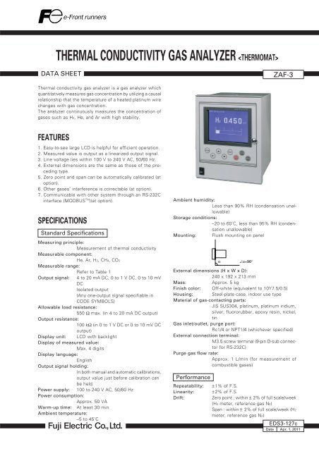
<strong>THERMAL</strong> <strong>CONDUCTIVITY</strong> <strong>GAS</strong> <strong>ANALYZER</strong> <br />
DATA SHEET<br />
ZAF-3<br />
Thermal conductivity gas analyzer is a gas analyzer which<br />
quantitatively measures gas concentration by utilizing a causal<br />
relationship that the temperature of a heated platinum wire<br />
changes with gas concentration.<br />
The analyzer continuously measures the concentration of<br />
gases such as H2, He, and Ar with high stability.<br />
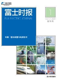
FEATURES<br />
1. Easy-to-see large LCD is helpful for efficient operation.<br />
2. Measured value is output as a linearized output signal.<br />
3. Line voltage lies within 100 V to 240 V AC, 50/60 Hz.<br />
4. External dimensions are the same as those of the preceding<br />
type.<br />
5. Zero point and span can be automatically calibrated (at<br />
option).<br />
6. Other gases’ interference is correctable (at option).<br />
7. Communicable with other system through an RS-232C<br />
interface (MODBUS TM )(at option).<br />
SPECIFICATIONS<br />
Standard Specifications<br />
Measuring principle:<br />
Measurement of thermal conductivity<br />
Measurable component:<br />
He, Ar, H2, CH4, CO2<br />
Measurable range:<br />
Refer to Table 1<br />
Output signal: 4 to 20 mA DC, 0 to 1 V DC, 0 to 10 mV<br />
DC<br />
Isolated output<br />
(Any one-output signal specifiable in<br />
CODE SYMBOLS)<br />
Allowable load resistance:<br />
550 Ω max. (in 4 to 20 mA DC output)<br />
Output resistance:<br />
100 kΩ (in 0 to 1 V DC or 0 to 10 mV DC<br />
output)<br />
Display unit: LCD with backlight<br />
Display of measured value:<br />
Max. 4 digits<br />
Display language:<br />
English<br />
Output signal holding:<br />
In both manual and automatic calibrations,<br />
output value just before calibration can<br />
be held.<br />
Power supply: 100 to 240 V AC, 50/60 Hz<br />
Power consumption:<br />
Approx. 50 VA<br />
Warm-up time: At least 30 min<br />
Ambient temperature:<br />
–5 to 45˚C<br />
Ambient humidity:<br />
Less than 90% RH (condensation unallowable)<br />
Storage conditions:<br />
–20 to 60˚C, less than 95% RH (condensation<br />
unallowable)<br />
Mounting: Flush mounting on panel<br />
α<br />
∠α=90°<br />
External dimensions (H x W x D):<br />
240 x 192 x 213 mm<br />
Mass:<br />
Approx. 5 kg<br />
Finish color: Off-white (equivalent to 10Y7.5/0.5)<br />
Housing: Steel-plate case, indoor use type<br />
Material of gas-contacting parts:<br />
JIS SUS304, platinum, platinum iridium,<br />
silver, fluororubber, epoxy resin, nickel,<br />
tin<br />
Gas inlet/outlet, purge port:<br />
Rc1/4 or NPT1/4 (whichever specified)<br />
External connection terminal:<br />
M3.5 screw terminal (9-pin D-sub connector<br />
for RS-232C)<br />
Purge gas flow rate:<br />
Approx. 1 L/min (for measurement of<br />
combustible gases)<br />
Performance<br />
Repeatability:<br />
Linearity:<br />
Drift:<br />
± 1% of F.S.<br />
± 2% of F.S.<br />
Zero point : within ± 2% of full scale/week<br />
(H2 meter, reference gas N2)<br />
Span : within ± 2% of full scale/week (H2<br />
meter, reference gas N2)<br />
EDS3-127c<br />
Date Apr. 1, 2011
ZAF-3<br />
Response time (90% response):<br />
High speed within 10 sec (at flow rate<br />
1L/min), allowed only for H2 meter (reference<br />
gas N2, without interference compensation)<br />
Standard within 60 sec (at flow rate 0.4<br />
L/min)<br />
Other gases’ interference:<br />
Indication error of each measured value<br />
(vol%)<br />
Interference<br />
component<br />
H2<br />
meter<br />
CH4<br />
meter<br />
Ar<br />
meter<br />
CO2<br />
meter<br />
H2 1% – +5.8 –6.5 –8.0<br />
CH4 1% +0.17 – –1.15 –1.38<br />
SO2 1% –0.31 –1.8 +2.1 +2.5<br />
Ar 1% –0.15 –0.87 – +1.2<br />
CO2 1% –0.125 –0.725 +0.83 –<br />
O2 1% +0.019 +0.11 –0.125 –0.15<br />
H2O 1.5°C saturation – – – –0.56<br />
Standard Gas Measurement Conditions<br />
Temperature: 0 to 50˚C<br />
Gas flow rate: Constant at 0.4 ± 0.05 L/min<br />
Constant at 1 ± 0.05 L/min(High responce)<br />
Dust:<br />
Less than 100 µg/Nm 3 with a particle size<br />
of 0.3 µm max<br />
Pressure: 10 kPa max<br />
Mist:<br />
Unallowable<br />
Oxygen gas: No oxygen should be contained in measured<br />
combustible gases.<br />
Moisture: Below saturation at 2˚C<br />
Corrosive gas: Unallowable<br />
Standard gases for calibration:<br />
Zero gas : same as reference gas or as<br />
specified<br />
Span gas : Concentration within 90 to<br />
100% of measuring range<br />
(Positive range)<br />
Concentration beyond 100%<br />
is inapplicable<br />
Installation Conditions<br />
• The analyzer should not be exposed to direct sunlight or<br />
radiation from a hot object.<br />
•A place subjected to heavy vibrations should be avoided.<br />
A location with clean atmosphere should be selected.<br />
•Before measuring combustible gases, the existing gases<br />
should be purged from the analyzer using air or N2.<br />
• When the analyzer is installed outdoors, it should be sheltered<br />
with a housing or cover to protect it from rain and<br />
wind.<br />
Optional Specifications<br />
Relay contact output:<br />
5 SPST relay contact outputs<br />
Relay contact capacity; 220 V AC/2 A (resistive<br />
load)<br />
Isolated with relay between contacts, and<br />
between contacts and internal circuit.<br />
Max. 5 points are selectable among<br />
those listed below.<br />
Zero-side solenoid valve drive output<br />
for automatic calibration<br />
Span-side solenoid valve drive output<br />
for automatic calibration<br />
Contact input:<br />
Suction pump OFF output in automatic<br />
calibration<br />
(reray “ON” immediately after<br />
turnning on power supply)<br />
Upper limit (1 point) concentration<br />
alarm output<br />
Lower limit (1 point) concentration<br />
alarm output<br />
Upper/Lower limit (1 point) concen<br />
-tration alarm output<br />
Upper limit (1 point) and lower limit<br />
(1 point) concentration alarm output<br />
(Total 2 points)<br />
High-high limit (1 point at each<br />
step) concentration alarm output<br />
(Total 2 points)<br />
Low-low limit (1 point at each<br />
step) concentration alarm output<br />
(Total 2 points)<br />
Analyzer error or automatic calibration<br />
error alarm output<br />
Calibrating status output<br />
Range information output (only with<br />
2-range meter)<br />
3 non-voltage contact inputs<br />
ON; 0 V, OFF; 5 V DC, current at ON; 5<br />
mA<br />
Isolated with photo coupler between inputs<br />
and internal circuit. Not isolated<br />
between contact inputs.<br />
The following actions can be input<br />
Remote holding of measured value<br />
output<br />
Remote range changeover (only with<br />
2-range meter)<br />
Remote start of automatic calibration<br />
Interference gas measured value input:<br />
Analog input for H2 meter interference<br />
correction (1 to 5 V DC, 1 range)<br />
Either CO2 or CH4 component of an external<br />
gas analyzer is to be input.<br />
Adjustment is required at Fuji Electric’s<br />
factory.<br />
Details of measurement gas will be<br />
checked when receiving an order.<br />
Automatic calibration function:<br />
Zero and span calibrations are automatically<br />
carried out at the predetermined intervals.<br />
Calibration gases are flowed sequentially<br />
by driving the externally installed solenoid<br />
valves.<br />
2
Communicating function:<br />
RS-232C (9-pin D-sub output)<br />
Half duplex, asynchronous<br />
MODBUS TM protocol, communication<br />
speed 9600 bps<br />
Contents of communication:<br />
Reading/writing of measured<br />
concentration values and various<br />
set values, and output of<br />
device status<br />
Remarks: For connection in RS-485,<br />
RS-232C/RS-485 converter<br />
should be provided seperately<br />
Explanation of Functions<br />
Output signal<br />
holding<br />
Remote output<br />
holding input<br />
Remote range<br />
changeover input<br />
Range identification<br />
signal output<br />
Automatic<br />
calibration<br />
When holding is set (user setting is turned ON), the latest measured value output just before output<br />
signal holding will be held during manual or automatic calibration, or by remote output holding input.<br />
In this status, indicated values will not be held.<br />
Upon short-circuiting the remote output holding input terminal when holding is set (user setting is<br />
turned ON), the latest measured value output will be held.<br />
Holding continues while the contact input terminal is close-circuited.<br />
In this period, indicated values will not be held.<br />
When remote range setting is selected (user setting is turned ON) for two rang type, range will be<br />
changed over according to the external signal input (non-voltage contact) applied to the remote range<br />
changeover input terminal.<br />
In this mode, range cannot be changed manually.<br />
When close-circuiting the contact input terminal, the first range is selected, and the second range is<br />
selected at open circuit.<br />
With two rang type, the current measuring range identification is output in contact signal.<br />
The contact output terminal is closed for the first range, and open for the second range.<br />
Zero and span calibrations are automatically carried out by outputting the signal for driving the<br />
externally installed solenoid valves for calibration gases at the set start time and interval or through<br />
input of the remote calibration start signal.<br />
• Calibration channel: 1 component<br />
• Calibration accuracy: ±0.2% of F.S.<br />
• Zero calibration point settable range: 0 to 100% of F.S.<br />
• Span calibration point settable range: 1 to 100% of F.S.<br />
• Calibration interval settable range: 1 to 99 hours (1 hour step) or 1 to 40 days (1 day step)<br />
• Calibration gas injection time settable range: 60 to 599 sec (in sec)<br />
• Calibration start: Internal timer or remote calibration start input<br />
• Solenoid valve drive signal output: SPST contact (zero x 1, span x 1)<br />
• Suction pump OFF output in calibration: SPST contact (suction pump OFF x 1)<br />
• Remote calibration start input: No-voltage contact input<br />
Automatic calibration is started by applying a non-voltage rectangular wave to the remote calibration<br />
start input terminal (opened after close-circuiting for 1.5 sec or longer).<br />
When contacts open, automatic calibration is carried out once.<br />
• Automatic calibration error alarm output: SPST contact<br />
Contacts close when the quantity of zero or span calibration exceeds 50% of full scale from the level of<br />
previous calibration, and contacts open when there is no abnormalities.<br />
When automatic calibration is abnormal, measurement output depends on the previous calibration<br />
values.<br />
• Automatic calibration status output: SPST contact<br />
During automatic calibration, contacts close, and open when within 50%.<br />
Upper/lower limit, Alarm contact output is issued with reference to the set upper/lower limit for alarm. Hysteresis is<br />
upper limit and lower settable.<br />
limit alarm output When measuring value exceed alarm setting value, contacts close, and open when not exceeded.<br />
SPST contact<br />
Analyzer error<br />
Interference<br />
correction by<br />
interference gas<br />
measured value<br />
input<br />
When the analyzer or automatic calibration is abnormal, contacts close, and open when normal.<br />
SPST contact<br />
Correction is made using either CO2 or CH4 component for H2 measurement.<br />
Measured H2 gas concentration is corrected in response to a concentration change of interference gas<br />
within its concentration range measured and set in advance.<br />
External interference gas measured value input : 1 to 5 V DC, 1range<br />
Interference gas fluctuation range : Reference concentration ± 20% F.S.<br />
H2 gas concentration correcting range : Reference concentration ± 25% F.S.<br />
Correction accuracy : ±5% F.S.<br />
(Note 1) Enter in the sample gas component check list on the back cover.<br />
(Note 2) Correction accuracy value is larger when other interference gas is contained in the sample gas.<br />
3
ZAF-3<br />
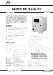
MEASURING PRINCIPLE<br />
Measuring<br />
chamber<br />
Sample gas<br />
Reference<br />
chamber<br />
This thermal conductivity gas analyzer measures gas concentration<br />
by utilizing the different thermal conductivities<br />
of 2 gas components. In the detector, there are reference<br />
and measuring chambers in each of which a thin platinum<br />
wire is stretched. The reference chamber is filled with reference<br />
gas and through the measuring chamber, sample<br />
gas is flowed. Each platinum wire composes a bridge circuit<br />
in combination with an external fixed resistor, and it is<br />
heated by flowing a constant current. When there is a change<br />
in the concentration of the component under measurement,<br />
the thermal conductivity of sample gas will change to affect<br />
the temperature of the platinum wire in the measuring<br />
chamber. The resulting thermal change is taken out as a<br />
change in electric resistance, according to which the concentration<br />
of measured gas is calculated.<br />
DC<br />
constant<br />
current<br />
Fixed resistor<br />
DC amplifier<br />
Thermal Conductivity Ratio of Gases<br />
Gases<br />
Sulfur dioxide gas<br />
Carbon dioxide gas<br />
Argon<br />
Carbon monoxide<br />
Steam (100°C)<br />
Air<br />
Nitrogen<br />
Oxygen<br />
Methane<br />
Hydrogen<br />
SO2<br />
CO2<br />
Ar<br />
CO<br />
H2O<br />
N2<br />
O2<br />
CH4<br />
H2<br />
Comparative thermal conductivity<br />
(0°C) when replacing thermal<br />
conductivity of air<br />
(2.41 x 10 -2 w/(m.k) with 1<br />
Table 1: Measurable Component and Measurable Range<br />
Measured gas<br />
H2<br />
He<br />
Ar<br />
CH4<br />
CO2<br />
Reference gas<br />
component (Note 1)<br />
N2, (CO2, Ar, He)<br />
N2, (CO2, Ar) O2,<br />
Air<br />
N2, O2, Air, (He)<br />
N2, (CO2, Ar, He)<br />
N2, O2, Air, (He)<br />
Measurable range<br />
0 to 3, 5, 10, 20, 50, 80, 100%<br />
100 to 90, 100 to 80%<br />
0 to 5, 10, 20, 30, 40, 50, 80, 100%<br />
100 to 90, 100 to 80%<br />
0 to 10, 20, 50, 80, 100%<br />
100 to 90, 100 to 80%<br />
0 to 20, 40, 50, 60, 80, 100%<br />
100 to 80%<br />
0 to 10, 20, 50, 100%<br />
100 to 90, 80%<br />
Range<br />
ratio(Note 2)<br />
1 : 10<br />
1 : 10<br />
(Note 1) Contact us for the components in the parentheses. H2 contained in O2 cannot be measured.<br />
(Note 2) Range ratio stands for maximum value.<br />
1 : 5<br />
1 : 5<br />
1 : 5<br />
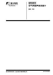
<strong>GAS</strong> SAMPLING SYSTEM DIAGRAM (EXAMPLE)<br />
Example of gas measurement in industrial furnace, sintering furnace, etc.<br />
Suction pump OFF signal in automatic calibration<br />
Sample<br />
gas<br />
(Note 1)<br />
Mist<br />
filter<br />
Gas<br />
aspirator<br />
(Note 2)<br />
Peltier gas<br />
cooler<br />
Flow<br />
checker<br />
Membrane<br />
filter<br />
0.4L/min (Note 3)<br />
or 1L/min<br />
1L/min<br />
Span calibration signal<br />
ZAF<br />
Exhaust<br />
Mist<br />
filter<br />
(Note 2)<br />
Drain pot<br />
Zero calibration signal<br />
Solenoid valve<br />
Purging<br />
air or<br />
nitrogen<br />
Pressure reducing valve<br />
Span<br />
gas<br />
Zero<br />
gas<br />
(Note 1) Dust must be purged adequately<br />
(for protection of the pump, flowmeter, etc.).<br />
(Note 2) Unnecessary if sample gas is dry.<br />
(Note 3) Select the one with no pulsating flow within the specified<br />
flow rate range.<br />
4
CODE SYMBOLS<br />
Digit<br />
4<br />
5<br />
6<br />
7<br />
8<br />
9<br />
10<br />
11<br />
12<br />
13<br />
14<br />
ZAF<br />
Description<br />
(Note 1)<br />
Indication in English, standard response<br />
Indication in English, high-speed response<br />
<br />
H2<br />
Ar<br />
He<br />
CH4<br />
CO2 (reference gas Ar unallowable)<br />
Other<br />
(Note 2)<br />
N2<br />
Air (incompatible with H2/CH4 measurement)<br />
O2 (incompatible with H2/CH4 measurement)<br />
Other<br />
<br />
AC100 to 240V 50/60Hz, Rc1/4<br />
AC100 to 240V 50/60Hz, NPT1/4<br />
<br />
<br />
0 to 3% (H2)<br />
0 to 5% (H2 ,He)<br />
0 to 10% (H2, He, Ar, CO2)<br />
0 to 20%<br />
0 to 30%<br />
0 to 50%<br />
0 to 80%<br />
0 to 100%<br />
100 to 90% (H2, He, Ar)<br />
100 to 80% (H2, He, Ar,CH4)<br />
Other<br />
(Note 3)<br />
None<br />
0 to 5% (H2 , He)<br />
0 to 10% (H2, He, Ar)<br />
0 to 20% (H2, He, Ar, CO2)<br />
0 to 30%<br />
0 to 50%<br />
0 to 80%<br />
0 to 100%<br />
Other<br />
<br />
DC4 to 20 mA<br />
DC0 to 1V<br />
DC4 to 20 mA + RS-232C communication<br />
DC 0 to 1 V + RS-232C communication<br />
DC0 to 10mV<br />
(Note 4)<br />
Provided<br />
(Note 5)<br />
None<br />
Provided<br />
<br />
None<br />
Automatic calibration<br />
Automatic calibration<br />
Concentration alarm<br />
Concentration alarm<br />
See table below.<br />
Contact output selection<br />
Contact output selection<br />
4<br />
E<br />
H<br />
5 6 7<br />
K<br />
L<br />
M<br />
E<br />
A<br />
Z<br />
4<br />
5<br />
6<br />
Z<br />
0<br />
1<br />
8 9 1011 12 13 14<br />
3 – –<br />
3<br />
Q<br />
L<br />
M<br />
N<br />
V<br />
P<br />
T<br />
J<br />
9<br />
8<br />
Z<br />
Y<br />
L<br />
M<br />
N<br />
V<br />
P<br />
T<br />
J<br />
Z<br />
A<br />
B<br />
C<br />
D<br />
E<br />
A<br />
Y<br />
A<br />
Y<br />
A<br />
B<br />
C<br />
D<br />
E<br />
F<br />
(Note 1) High-speed response is for H2 meter<br />
used for reference gas N2 only.<br />
(Note 2) Reference gas refers to gas other<br />
than the component to be<br />
measured in sample gas.<br />
("Z" must be specified when interference<br />
gas is to be contained.)<br />
(Note 3) The ratio of maximum range to<br />
the first range is as given below.<br />
For CO2, Ar or CH4 measurement<br />
: 1st range x 5 (times)<br />
For He or H2 measurement<br />
: 1st range x 10 (times)<br />
A range from 0 to ...%<br />
cannot be combined with<br />
that from 100 to ...%.<br />
1st range < 2nd range<br />
(Note 4) Specify Y if linearization in the 12th digit<br />
is not required.<br />
(Note 5) A CO2 or CH4 meter needs to be<br />
prepared separately.<br />
A reverse range such as 100 to 0%<br />
cannot be specified.<br />
Input signal is 1 to 5 V DC.<br />
Adjustment is required at Fuji Electric’s<br />
factory.<br />
Details of measurement gas will be<br />
checked when receiving an order.<br />
Reverse range such as 100% to 0%<br />
cannot be specified.<br />
Cannot be specified if high-speed<br />
response is selected.<br />
Input/output contact specifications<br />
14th digit : A 14th digit : B<br />
Automatic calibration<br />
Automatic Zero gas valve drive<br />
calibration Span gas valve drive<br />
Suction pump OFF in automatic calibration<br />
(DO1)<br />
(DO2)<br />
(DO3)<br />
(DO1)<br />
(DO2)<br />
(DO3)<br />
Contact output<br />
Contact<br />
input<br />
Concentration<br />
alarm<br />
Upper limit (1 point) concentration alarm<br />
Lower limit (1 point) concentration alarm<br />
Upper/lower limit (1 point as a set)<br />
concentration alarm<br />
Upper limit (1 point) and lower limit<br />
(1 point) concentration alarm<br />
2-step upper limit (1 point each)<br />
concentration alarm<br />
2-step lower limit (1 point each)<br />
concentration alarm<br />
Other Calibration status<br />
Range information (2-range meter) (Note 3)<br />
Analyzer error or automatic calibration error<br />
Remote automatic calibration start (Note 4)<br />
Remote range changeover (2-range meter) (Note 5)<br />
Remote measured value output holding (Note 6)<br />
—<br />
—<br />
—<br />
—<br />
—<br />
—<br />
(DO4)<br />
—<br />
(DO5)<br />
(DI3)<br />
(DI2)<br />
(DI1)<br />
—<br />
—<br />
—<br />
—<br />
—<br />
—<br />
(DO4)<br />
—<br />
(DO5)<br />
(DI3)<br />
(DI2)<br />
(DI1)<br />
(Note 1) Mark : Normally Open (NO) contact<br />
(Note 2) Mark : Normally Closed (NC) contact,after turning on power supply<br />
(Note 3) Low range : Contacts close, High range : Contacts open<br />
(Note 4) When contacts open 1.5 sec after their closure, automatic calibration starts.<br />
(Note 5) Contacts closed : Low range, Contacts open : High range<br />
(Note 6) Contacts closed : Holding, Contacts open : Holding canceled<br />
(Note 7) Up to 5 contact output points can be selected.<br />
14th digit : C 14th digit : D<br />
Concentration alarm<br />
—<br />
—<br />
—<br />
Any one<br />
alarm<br />
settable<br />
on screen<br />
(DO1, 2)<br />
2 Point<br />
(NO) Contact<br />
(DO4)<br />
(DO3)<br />
(DO5)<br />
(DI3)<br />
(DI2)<br />
(DI1)<br />
—<br />
—<br />
—<br />
Any one<br />
alarm<br />
settable<br />
on screen<br />
(DO1, 2)<br />
2 Point<br />
(NC) Contact<br />
(DO4)<br />
—<br />
(DO5)<br />
(DI3)<br />
(DI2)<br />
(DI1)<br />
14th digit : E 14th digit : F<br />
Contact output selection (Note 7)<br />
Any one<br />
alarm<br />
settable<br />
on screen<br />
2 Point<br />
(NO) Contact<br />
(DI3)<br />
(DI2)<br />
(DI1)<br />
Any one<br />
alarm<br />
settable<br />
on screen<br />
2 Point<br />
(NC) Contact<br />
(DI3)<br />
(DI2)<br />
(DI1)<br />
5
ZAF-3 ZRJ<br />
OUTLINE DIAGRAM (Unit : mm)<br />
192<br />
Panel<br />
1.6 < t < 10<br />
t<br />
193<br />
169 (24)<br />
140<br />
<strong>GAS</strong> <strong>ANALYZER</strong><br />
240<br />
230<br />
(248)<br />
(268)<br />
MODE<br />
ESC<br />
ZERO<br />
ENT<br />
SPAN<br />
Front view<br />
Side view<br />
Mounting brackets<br />
External terminal (option)<br />
M3.5 screw<br />
(43)<br />
(35)<br />
Rc1/4 or NPT1/4 (whichever specified)<br />
INLET<br />
Panel cutout<br />
184 +2<br />
0<br />
240<br />
230<br />
1 11<br />
2 12<br />
3 13<br />
4 14<br />
5 15<br />
6 16<br />
7 17<br />
8 18<br />
9 19<br />
1020<br />
INLET<br />
130<br />
232 +2<br />
0<br />
OUTLET<br />
1 2 3 4 5<br />
182<br />
192<br />
External terminal (standard)<br />
M3.5 screw<br />
Rear view<br />
PURGE<br />
Rc1/4 or NPT1/4 (whichever specified)<br />
OUTLET<br />
Rc1/4 or NPT1/4 (whichever specified)<br />
Purging port<br />
RS-232C/Dsub 9P (whichever specified)<br />
CONNECTION DIAGRAM<br />
(Standard)<br />
(Option) 13th digit A and 14th digit A, B, C, D, E, F<br />
1<br />
2<br />
3<br />
4<br />
5<br />
L<br />
N<br />
E<br />
+<br />
–<br />
Power supply 100 to 240V AC, 50/60Hz<br />
Grounding terminal<br />
Measured value output (as specified)<br />
4 to 20mA DC<br />
0 to 1V DC<br />
0 to 10mV DC<br />
Interference correcting<br />
input 1 to 5V DC<br />
Remote output holding<br />
Remote range changeover<br />
Remote automatic calibration start<br />
AIN+<br />
AIN–<br />
DI1<br />
DI1<br />
DI2<br />
DI2<br />
DI3<br />
DI3<br />
1 11 DO1<br />
2 12 DO1<br />
3 13 DO2<br />
4 14 DO2<br />
5 15 DO3<br />
6 16 DO3<br />
7 17 DO4<br />
8 18 DO4<br />
9 19 DO5<br />
10 20 DO5<br />
Contact output 1<br />
Contact output 2<br />
Contact output 3<br />
Contact output 4<br />
Contact output 5<br />
Refer to “Input/output contact specifications” in CODE SYMBOLS.<br />
6
SCOPE OF DELIVERY<br />
Analyzer main unit<br />
Panel mounting brackets (1 set)<br />
2 power fuses (250 V AC, 1 A)<br />
Instruction Manual<br />
ITEMS TO BE PREPARED SEPARATELY<br />
Gas sampling equipment, standard gas, receiving instrument,<br />
etc.<br />
With interference corrective calculation: CH4 or CO2 gas<br />
analyzer<br />
ORDERING INFORMATION<br />
1. Analyzer type<br />
2. Gas component to be measured<br />
3. Measuring range<br />
4. Gas component other than measured<br />
Very important information required to achieve intended<br />
accuracy of the instrument.<br />
(Enter in “Table for checiking sample gas component”on<br />
the next page.)<br />
7
ZAF-3<br />
<br />
Let us check your sample gas for safe use of Fuji Electric’ gas analyzer.<br />
Make entries where you can answer. If there is any question, contact our salesperson in charge of your company.<br />
The analyzer may not provide full performance depending on other gas components contained in sample gas.<br />
Item<br />
Name of customer at<br />
delivery destination<br />
Description<br />
Date<br />
Application, purpose<br />
Gas component to be<br />
measured<br />
Component to be<br />
measured<br />
Sample gas<br />
Minimum<br />
concentration (%)<br />
Normal<br />
concentration (%)<br />
Maximum<br />
concentration (%)<br />
Remarks<br />
Other<br />
component gas<br />
Other<br />
component gas<br />
Interference gas<br />
input<br />
Your question,<br />
etc.<br />
Measuring range<br />
0-<br />
CO2 meter or<br />
CH4 meter<br />
Customer<br />
information<br />
Company name<br />
Section<br />
Address<br />
TEL<br />
Person in charge<br />
Fuji Electric’s salesperson in charge of your company<br />
Caution on Safety<br />
*Before using this product, be sure to read its instruction manual in advance.<br />
International Sales Div<br />
Sales Group<br />
Gate City Ohsaki, East Tower, 11-2, Osaki 1-chome,<br />
Shinagawa-ku, Tokyo 141-0032, Japan<br />
http://www.fujielectric.com<br />
Phone: 81-3-5435-7280, 7281 Fax: 81-3-5435-7425<br />
http://www.fjielectric.com/products/instruments/<br />
Information in this catalog is subject to change without notice.<br />
Printed in Japan