selos
fasis - Wieland
fasis - Wieland
- No tags were found...

Create successful ePaper yourself
Turn your PDF publications into a flip-book with our unique Google optimized e-Paper software.
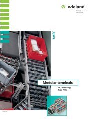
<strong>selos</strong> BIT<br />
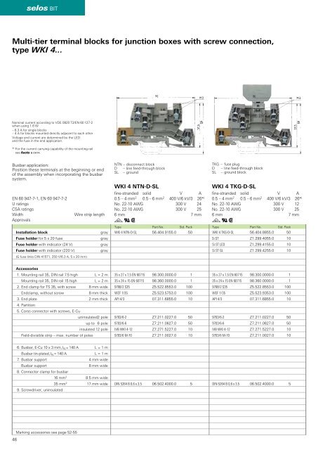
Multi-tier terminal blocks for junction boxes with screw connection,<br />
type WKI 4...<br />
Nominal current according to VDE 0820 T2/EN 60 127-2<br />
when using 1.6 W<br />
– 6.3 A for single blocks<br />
– 4 A for blocks mounted directly adjacent to each other<br />
Voltage and current are determined by the LED<br />
and the fuse in the end application.<br />
* ) For the current carrying capability of the mounting rail<br />
see facts & DATA<br />
Busbar application:<br />
Position these terminals at the beginning or end<br />
of the assembly when incorporating the busbar<br />
system.<br />
EN 60 947-7-1, EN 60 947-7-2<br />
U ratings<br />
CSA ratings<br />
Width<br />
Approvals<br />
Installation block<br />
Fuse holder for 5 x 20 fuse<br />
Fuse holder with indicator (24 V)<br />
Fuse holder with indicator (220 V)<br />
(G fuse-links DIN 41571, 250 V/6.3 A, 5 x 20 mm)<br />
Wire strip length<br />
gray<br />
gray<br />
gray<br />
gray<br />
NTN – disconnect block<br />
D – line feed-through block<br />
SL – ground<br />
WKI 4 NTN-D-SL<br />
fine-stranded solid V A<br />
0.5 – 4 mm 2 0.5 – 6 mm 2 400 V/6 kV/3 26* )<br />
No. 22-10 AWG 300 V 24<br />
No. 22-10 AWG 300 V 25<br />
6 mm 7 mm<br />
gqw<br />
WKI 4 NTN-D-SL 56.404.9155.0 50<br />
TKG – fuse plug<br />
D – line feed-through block<br />
SL – ground block<br />
WKI 4 TKG-D-SL<br />
fine-stranded solid V A<br />
0.5 – 4 mm 2 0.5 – 6 mm 2 400 V/6 kV/3 26* )<br />
No. 22-10 AWG 300 V 12<br />
No. 22-10 AWG 300 V 25<br />
6 mm 7 mm<br />
gqw<br />
Type Part No. Std. Pack Type Part No. Std. Pack<br />
WKI 4 TKG-D-SL 56.404.8855.0 50<br />
Si ST Z1.299.4055.0 10<br />
Si ST LED Z1.299.4155.0 10<br />
Si ST GL Z1.299.4255.0 10<br />
Accessories<br />
1. Mounting rail 35, DIN rail 7.5 high L = 2 m<br />
Mounting rail 35, DIN rail 15 high L = 2 m<br />
2. End clamp for TS 35, with screw 8 mm wide<br />
Endclamp, without screw<br />
8 mm thick<br />
3. End plate 2 mm thick<br />
4. Partition<br />
5. Corss connector with screws, E-Cu<br />
uninsulated 2 pole<br />
up to 6 pole<br />
insulated 12 pole<br />
Field-divisible strip – max. number of poles<br />
35 x 27 x 7,5 EN 60715 98.300.0000.0 1<br />
35 x 24 x 15 EN 60715 98.360.0000.0 1<br />
9708/2 S35 Z5.522.8553.0 100<br />
WEF 1/35 Z5.523.5753.0 100<br />
API 4/3 07.311.6855.0 10<br />
9703/6-2 Z7.211.0227.0 50<br />
9703/6-6 Z7.211.0627.0 50<br />
IVB WKI 4-12 Z7.271.5227.0 10<br />
9703/6 M-70 Z7.211.0027.0 10<br />
35 x 27 x 7,5 EN 60715 98.300.0000.0 1<br />
35 x 24 x 15 EN 60715 98.360.0000.0 1<br />
9708/2 S35 Z5.522.8553.0 100<br />
WEF 1/35 Z5.523.9353.0 100<br />
API 4/3 07.311.6855.0 10<br />
9703/6-2 Z7.211.0227.0 50<br />
9703/6-6 Z7.211.0627.0 50<br />
IVB WKI 4-12 Z7.271.5227.0 10<br />
9703/6 M-70 Z7.211.0027.0 10<br />
6. Busbar, E-Cu 10 x 3 mm, I N = 140 A L = 1 m<br />
Busbar tin-plated, I N = 140 A<br />
L = 1 m<br />
7. Busbar support 4 mm wide<br />
Busbar support<br />
8 mm wide<br />
8. Connector clamp for busbar<br />
16 mm 2 8.5 mm wide<br />
35 mm 2 17 mm wide<br />
9. Screwdriver, uninsulated<br />
DIN 5264 B 0,6 x 3,5 06.502.4000.0 5<br />
DIN 5264 B 0,6 x 3,5 06.502.4000.0 5<br />
46<br />
Marking accessories see page 52-55