

Amateur Radio Today - Free and Open Source Software
Amateur Radio Today - Free and Open Source Software
Amateur Radio Today - Free and Open Source Software
- No tags were found...

You also want an ePaper? Increase the reach of your titles
YUMPU automatically turns print PDFs into web optimized ePapers that Google loves.
Number 8 on your Feetlbec k card<br />
Building <strong>and</strong> Using<br />
N7APE's NiCd Zapper<br />
An update.<br />
by Marion D. Kitchens K4GOK<br />
"[n the September 1992 issue of 73 AmLlteur<br />
J.<strong>Radio</strong> <strong>Today</strong>, Ed Miller N7APE described<br />
a c ircuit for recovering NiCd batteries that<br />
have grown internal shorts. His article got<br />
my immediate attention because it seemed<br />
like a simple solution to a proble m that<br />
plagues many of us. Most of us have numbers<br />
ofjust such NiCds. If you do much with<br />
NiCd batteries around the ham shack, then<br />
you will definitely want to build N7APE's<br />
circuit. Some hams have been known to bum<br />
out internal NiCd shorts by momentarily<br />
connecting them to an automobile battery.<br />
This can be dangerous, <strong>and</strong> is not recommended.<br />
N7APE's circuit can eliminate that<br />
danger <strong>and</strong> still recover the shorted NiCds.<br />
Furthennore, after clearing the short, the circuit<br />
will automatically switch into the charge<br />
mode <strong>and</strong> recharge the battery. A preuy neat<br />
circuit!<br />
This article describes the experiences of<br />
two builders of N7APE's circuit, <strong>and</strong> relays<br />
the experience <strong>and</strong> knowledge they gained<br />
about recovering NiCds.<br />
Building T he Circuit<br />
Gene W0DlQ <strong>and</strong> I both built "Zappers"<br />
according to N7APE's article. The original<br />
publication cont a in ed one error in the<br />
schematic: The correct value of R5 should be<br />
560k, as per the parts list, <strong>and</strong> not the 560<br />
ohm value shown on the schematic. More on<br />
optimizing the value of this resistor later. The<br />
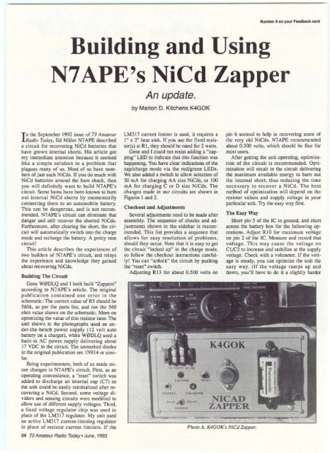
unit shown in the photographs used an under-the-bench<br />
power supply (12 volt auto<br />
battery on a charger), while W0Dl Q used a<br />
built-in AC power supply delivering about<br />
17 VDC to the circuit. The unmarked diodes<br />
in the original publication are IN914 or similar.<br />
Being experimenters. both of us made minor<br />
changes in N7APE's ci rcuit. First, as an<br />
operating convenience, a " reset" switch was<br />
added to discharge an internal cap (C7) so<br />
the unit could be easily reinitialized after recovering<br />
a NiCd. Second, some voltage dividers<br />
<strong>and</strong> sensing circuits were modified to<br />
allow use of d ifferent supply voltages. Third,<br />
a fixed voltage reg ulator ch ip was used in<br />
place of the LM31 7 regulator. My unit used<br />
an active LM317 current-limiting regulator<br />
in place of resi stor current limiters. If the<br />
34 73 <strong>Amateur</strong> <strong>Radio</strong> <strong>Today</strong>· June. 1993<br />
LM3 17 current limiter is used, it req uires a<br />
I" x 2" hea t sink. If you use the fixed res iston<br />
s) at R1, they should be rated for 2 watts.<br />
Gene <strong>and</strong> I could not resist adding a "zapping"<br />
LED to indicate that this function was<br />
happening. You have clear indications of the<br />
zap/charge mode via the red/green LEOs.<br />
We also added a switch to allow selection of<br />
50 rnA for charging AA size NiCds, or 100<br />
rnA fo r charging C or D size NiCds. The<br />
changes made in our circuits are shown in<br />
Figures I <strong>and</strong> 2,<br />
Checkout <strong>and</strong> Adjustments<br />
Several adjustments need to be made after<br />
assembly. The sequence of checks <strong>and</strong> adjustments<br />
shown in the sidebar is recommended.<br />
This list provides a sequence that<br />
allows fo r easy re sol ut ion of problems,<br />
should they occur. Note that it is easy to get<br />
the circuit " locked up" in the charge mode,<br />
so follow the checkout instructions carefully!<br />
You can " unlock" the circuit by pushin g<br />
the "reset" switch.<br />
Adjust ing RI3 for about 0.500 volts on<br />
.)<br />
VO U "OI<br />
•<br />
-CII.. tGI "I G<br />


