

Amateur Radio Today - Free and Open Source Software
Amateur Radio Today - Free and Open Source Software
Amateur Radio Today - Free and Open Source Software
- No tags were found...

Create successful ePaper yourself
Turn your PDF publications into a flip-book with our unique Google optimized e-Paper software.
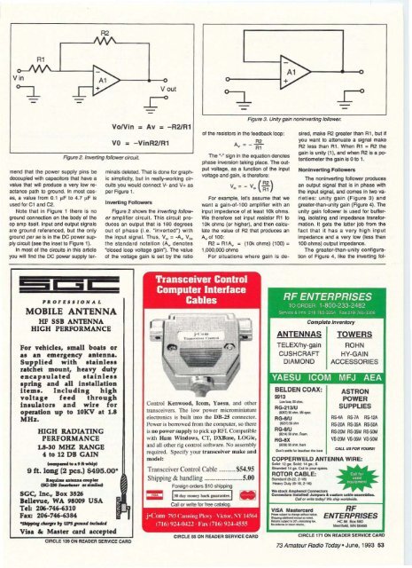
R2<br />
V in<br />
Rl<br />
- -<br />
mend that the power supply pins be<br />
decouplecl with capacitors thai have a<br />
value fhat win produce a vel)' low reactance<br />
path to ground. In most eases,<br />
a value lrom 0.1 ~ F 10 4.7 ~ F Is<br />
usec ror C1 <strong>and</strong> C2.<br />
Note that in Figure 1 th ere is no<br />
ground connection on the body 01 the<br />
op amp llsell . Input <strong>and</strong> output signals<br />
are ground reterenced, bu t the only<br />
ground per se is in the DC power supply<br />
circuit (see the Insel to FIQure 1).<br />
mmosl 01 the Circuits in this article<br />
you win flfld the DC power supply ter-<br />
-<br />
V out<br />
VoNI" = Av = -R2IR1<br />
VO<br />
= - Vln R2IRl<br />
rrinals deleted. That is oone for graphic<br />
simpliCity, b1.lt In reatly-worll.lng Cirwits<br />
you would conned V- <strong>and</strong> V+ as<br />
per Figure 1.<br />
Inverting Followers<br />
Figure 2 shows the Inverting folJower<br />
amplifier circuit. This circuit produces<br />
an output that Is 180 degrees<br />
out of phase (i.e. "inve rted") with<br />
the Inpul signal. Thus, V o '" -A." V...<br />
th e st<strong>and</strong>ard notaUon (A" denotes<br />
"closed loop voltage gain1. The value<br />
of the voltage gain is set by the ratiO<br />
"""l<br />
~<br />
+<br />
,<br />
r<br />
- -<br />
FIgUre 3. Unity gam nomnvertmg followe£.<br />
of the resistors in the feedback loop:<br />
R2<br />
/1\,, - - R'<br />
The "0" Sign in the equation deooles<br />
phase inYersiofl taking place. The output<br />
YOita ge. as a function of the input<br />
voltage <strong>and</strong> gain, is therefore:<br />
Vo = -Vo ( ~ )<br />
For example. lers assume thai we<br />
want a 9aln-ol· 1oo amplifier with an<br />
input impedance 01 at least 10k ohms.<br />
We therefore set input resistor Rl to<br />
10k ohms (or higher), <strong>and</strong> then caeulate<br />
the value 01 R2 that produces an<br />
A... of 100:<br />
R2 = R1A,. ~ (10k ohms) (1 00) a<br />
l ,OOO,OOO otvnS<br />
For situations where ga in is desired,<br />
make R2 greater than a t. but it<br />
you want to attenuate a signal make<br />
R2 tess than Rl . When Rl _ R2 the<br />
ga .... is umy (1), <strong>and</strong> Wh8n R2 is a polenliomet<br />
Bl" the ga in Is 0 10 1.<br />
Nonlnverling FDlk)wers<br />
The nonW1veftinQ lo/Iower produces<br />
an output Signal that is in phase with<br />
the input signal, <strong>and</strong> comes In two varieti<br />
es: un ity gain (Figure 3) <strong>and</strong><br />
greater-thall-unity gain (Figure 4). The<br />
unity gain rollowe r is used for butlering,<br />
Isolating <strong>and</strong> tmoecarce transformation.<br />
It gets the laller job from the<br />
fact that it has a v ery high input<br />
Impedance <strong>and</strong> a very low (less than<br />
100 ohms) outPut Impedance.<br />
The g reater-than-unity configuration<br />
of Figure 4, like lh8 inverting 101-<br />
MOBILE ANTENNA<br />
HF SSB ANTENNA<br />
HIGH PERFORMANCE<br />
For vehicles, . mall bo,at. or<br />
at an emergency antenna.<br />
Supplied with . tainle..<br />
ratchet mount, heavy duty<br />
eDcap.ubted . talnle..<br />
.pring <strong>and</strong> all inllallatioD<br />
item.. [ndudinl high<br />
voltaIe feed t h r o u g h<br />
in.ulator. <strong>and</strong> wire for<br />
operation up to 10KV at 1.8<br />
MHz.<br />
HIGH KADiATlNG<br />
PERFORMANCE<br />
1.8-30 MHZ RANGE<br />
4 t. 12 DB GAIN<br />
....,.......,..Id'i<br />
9 ft. long (2 pcs.) $495.00'<br />
.~..... . ' • • m.p<br />
C3G-DO S. _ • ••,,~<br />
sec,. [nc.,. Box 3526<br />
Bellevue, WA 98009 USA<br />
To.: 206-746-6310<br />
Fax: 206-746-6384<br />
~ ' \ pLv d-p• ., W'S.,-. h+d'"<br />
Vi.. &: Muter card accepted<br />
CIRCLE 139 ON READER SERVICE CARD<br />
.... ,-<br />
- I •<br />
COfItrOl Kenw ood, Icom, Yaesu. <strong>and</strong> other<br />
uansceivers. The low power mk romlmarure<br />
elecrrcmcs is buill into the DB-15 connector.<br />
Power is borrowed from the computer, so there<br />
is no power supply 10 pick up RA. Compatible<br />
w ith Ham Windows, CT, u xuese. I.OGIc,<br />
<strong>and</strong> all other rig control soft ware. N o assembly<br />
required. Specify your tre nscefver make <strong>and</strong><br />
model:<br />
Transceiver Control Cable<br />
j-Com 7'1.' ( ';lnlli,,!: I~"~ . \ ·k't" r . "<br />
SS4.95<br />
Sh.ipping & h<strong>and</strong>ling 5.00<br />
FOJeign 0l'dElI$ S10 $hiR:ling<br />
::iiC I"..,-,'"" ........··1..<br />
Cat or write lor tree catalog .<br />
(71ttI9z.f-I).ll l . Fa\ 17 161 9z.f-4555<br />
J-l~<br />
CIRCLE 55 ON READER SERViCE CA RD<br />
RF ENTERPRISES<br />
TO ORDER 1-800-233-2482<br />
Se'\tlce & Info 2 18-765-3254 Fa ~ 2 18 76,,·3308<br />
ANTEI'!NAS<br />
TELEXlhy-gain<br />
CUSHCRAFT<br />
DIAMOND<br />
BELDEN COAX:<br />
.." ........"'<br />
RG·213IU<br />
fIi!I7I Sl<br />
RG-llIU<br />
_ .~<br />
__<br />
Complete Inventory<br />
TOWERS<br />
ROHN<br />
HY-GAIN<br />
ACCESSORIES<br />
YAESU ICOM MFJ AEA<br />
ASTRON<br />
POWER<br />
SUPPLIES<br />
RS--CA RS-7A<br />
RS- IV.<br />
RS-2llA RS-35A RS-5OA.<br />
AS,2I».I RS-35M AS.sa.1<br />
RG-llIU<br />
(&mISO otrn._<br />
AG·8X<br />
Imll"'''''''''_<br />
Oon'_"'_ "'_<br />
COPPERWELD ANTENNA WIRE:<br />
S


