

Amateur Radio Report Card
1 - Free and Open Source Software
1 - Free and Open Source Software
- No tags were found...

Create successful ePaper yourself
Turn your PDF publications into a flip-book with our unique Google optimized e-Paper software.
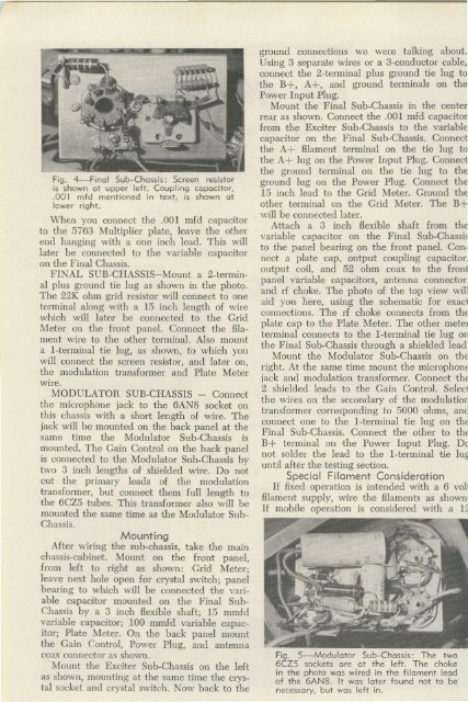
Fig. 4-Final Sub-Chassis : Screen resi.stor<br />
is shown at upper left. Coupling capacitor,<br />
.001 mfd mentioned in text, is shown at<br />
lower right.<br />
When you connect the .001 mfd capacitor<br />
to the 5763 Multiplier plate, leave the other<br />
end hanging with a one inch lead. This will<br />
later be connected to the variable capacitor<br />
on the Final Chassis.<br />
F INAL SUB -C IIASS IS- ~ [oun t a 2-terminal<br />
plus ground tie lug as shown in the photo.<br />
The 22K ohm grid resistor will con nect to one<br />
terminal along with a 15 inch length of wire<br />
which will later be con nected to the Grid<br />
Meter on the front panel. Connect the filament<br />
wire to the other terminal. Also mount<br />
a I-terminal tie lug, as shown, to which you<br />
w iII connect the screen resistor, and later on,<br />
the modulation transformer and Plate Meter<br />
wire.<br />
MODULATOR SUB-CHASSIS -<br />
Connect<br />
the microphone jack to the 6ANS socket on<br />
this chassis with a short length of wire. The<br />
jack will be mounted on the back panel at the<br />
same time the Modulator Sub-Chassis is<br />
mounted. The Gain Con trol on the back panel<br />
is connected to the Modulator Sub-Chass is by<br />
two 3 inch lengtbs of shielded wire. Do not<br />
cut the primary leads of tbe modulation<br />
transformer, but connect them fuII length to<br />
the 6CZ5 tubes. T his transformer also will be<br />
mounted the same time as the Modulator Sub<br />
Chassis.<br />
Mounting<br />
After wiring the sub-chassis, take the main<br />
chassis-cabinet. Mount on the front panel,<br />
from left to right as shown: Grid Meter;<br />
leave next hole open for crystal switch; panel<br />
bearing to which will be connected the variable<br />
capacitor mounted on the Final Sub<br />
Chassis by a 3 inch flexible shaft; 15 mmfd<br />
variable capacitor; 100 mmfd variable capacitor;<br />
Plate Meter. On the back panel mount<br />
the Gain Control, Power Plug, and antenna<br />
coax connector as shown .<br />
Mount the Exciter Sub-Chassis on the left<br />
as shown, mounting at the same time the crystal<br />
socket and crystal switch. Now back to the<br />
ground connections we were talking about.<br />
Using 3 separate wires or a 3-conduct.or cable,<br />
connect the 2-terminal plus ground tie lug to<br />
the B+ , A+ , and ground terminals on the<br />
Power Input Plug.<br />
Mount the Final Sub.Chassis in the center<br />
rear as shown. Connect the .001 mfd capacitor<br />
from the Exciter Sub-Chassis to the variable<br />
capacitor on the Final Sub-Chassis. Connect<br />
the A+ filament terminal on the tie lug to<br />
the A+ lug on the Power Input Plug. Connect<br />
the ground terminal on the tie lug to the<br />
ground lug on the Power Plug. Connect the<br />
15 inch lead to the Grid Meter. Ground the<br />
other terminal on the Grid Meter. The B+<br />
will be connected later.<br />
Attach a 3 inch flexible shaft from the<br />
variable capacitor on the Final Sub-Chassis<br />
to the panel bearing on the front panel. Connect<br />
a plate cap, output coupling capacitor,<br />
output coil, and 52 ohm coax to the front<br />
panel variable capacitors, antenna connector.<br />
and rf choke. The photo of the top view will<br />
aid you here, using the schematic for exact<br />
connections. The rf choke connects from the<br />
plate cap to the Plate Meter. The other meter<br />
terminal connects to the I-terminal tie lug on<br />
the Final Sub-Chassis through a shielded lead<br />
Mount the<br />
Modulator Sub-Chassis on the<br />
right. At the same time mount the microphone<br />
jack and modulation transformer. Connect the<br />
2 shielded leads to the Gain Cou trol. Select<br />
the wires on the secondary of the modulatior<br />
transformer corresponding to 5000 ohms, ani<br />
connect one to the I-terminal tie lug on the<br />
Final Sub-Chassis. Connect the other to the<br />
B+ terminal on the Power Input Plug. De<br />
not solder the lead to the I-terminal tie IUE<br />
until after the testing section.<br />
Special Filament Consideration<br />
If fixed operation is intended WIth a 6 vof<br />
filament supply, wire the filaments as shown<br />
If mobile operation is considered with a H<br />
Fig . 5- Modulator Sub-Chassis: The two<br />
6CZS sockets are at the left. The choke<br />
in the photo was wi red in the filament lead<br />
of the 6AN8. It was later found not to be<br />
necessary, but was left in.


