

Amateur Radio Report Card
1 - Free and Open Source Software
1 - Free and Open Source Software
- No tags were found...

Create successful ePaper yourself
Turn your PDF publications into a flip-book with our unique Google optimized e-Paper software.
Herbert Cross KIAMN<br />
59 Fla gler Ave .<br />
Cheshire, Conn.<br />
Improving the Paco GDO<br />
I purchased the Paco G-14 grid dip meter<br />
in kit form about four months ago. I assembled<br />
it and found that it worked quite well on all<br />
but the highest frequency range ( 110-250<br />
mc). There was very little indication of grid<br />
current over much of the tuning range. This<br />
was traced to a defective sensitivity control<br />
which left a small bias on the meter. When<br />
I shorted out the control I was able to get a<br />
usahle reading, but now, I found so many<br />
spurious responses that the instrument was<br />
still of little use over this frequency range.<br />
At this point it was back to the drawing<br />
board for a long look at the circuit diagram<br />
where a new problem became apparent. Even<br />
with the sensitivity control working properly<br />
the meter would be shunted with the 270<br />
ohm resistor, R4, which would lower its sensitivity<br />
anyway. The problem was a twofold<br />
one. I had to kill the residual bias from the<br />
sensitivity control and also block the shunting<br />
action of the resistor, R4. I decided to<br />
insert a small silicon diode between the sensitivity<br />
control and R4 with its cathode towards<br />
R4. In this application I hoped to use<br />
the forward voltage drop of the diode to<br />
solve both my problems. The result far exceeded<br />
my hopes. I now obtained grid current<br />
indication varying from a low of 70 uA. to a<br />
high of 250 uA. and the sensitivity control<br />
functioned nicely. To make sure that the<br />
diode wouldn't misbehave I bypassed both<br />
sides of it to ground with .02 ceramic discs<br />
(probably unnecessary) and established a di-<br />
AUCUST 1965<br />
., .<br />
..~ .<br />
,<br />
to B+<br />
S£P&TIVITT<br />
",<br />
'"<br />
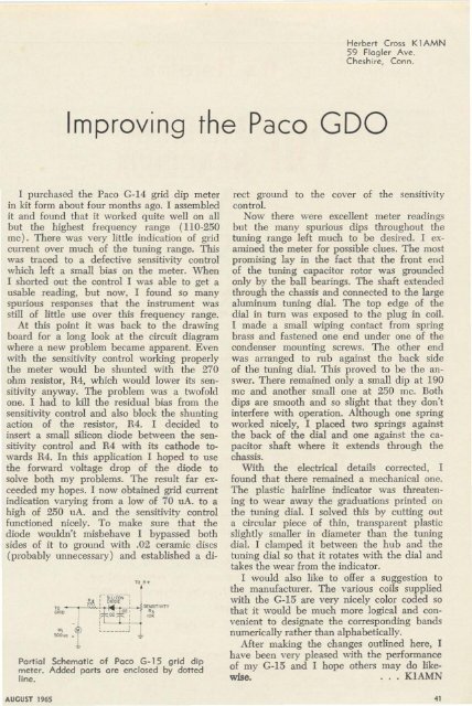
Partial Schematic of Poco G- 1S g rid dip<br />
meter. Added ports are enclosed by dotted<br />
line.<br />
rect ground to the cover of the sensitivity<br />
control.<br />
Now there were excellent meter readings<br />
but the many spurious dips throughout the<br />
tuning range left much to be desired. I examined<br />
the meter for possible clues. The most<br />
promising lay in the fact that the front end<br />
of the tuning capacitor rotor was grounded<br />
only by the ball bearings. The shaft extended<br />
through the chassis and connected to the large<br />
aluminum tunin g dial. The top edge of the<br />
dial in tum was exposed to the plug in coil.<br />
I made a small wiping contact from spring<br />
hrass and fastened one end under one of the<br />
condenser mounting screws. The other end<br />
was arranged to rub against the back side<br />
of the tuning dial. This proved to be the answer.<br />
There remained only a small dip at 190<br />
mc and another small one at 250 me. Both<br />
dips are smooth and so slight that they don't<br />
interfere with operation. Although one spring<br />
worked nicely, I placed two springs against<br />
the back of the dial and one against the capacitor<br />
shaft where it extends through the<br />
chassis.<br />
With the electrical details corrected, I<br />
found that there remained a mechanical one.<br />
The plastic hairline indicator was threatening<br />
to wear away the graduations printed on<br />
the tuning dial. I solved this by cutting out<br />
a circular piece of thin, transparent plastic<br />
sligh tly smaller in diameter than the tuning<br />
dial. I clamped it between the hub and the<br />
tuning dial so that it rotates with the dial and<br />
takes the wear from the indicator.<br />
I would also like to offer a suggestion to<br />
the manufacturer. The various coils supplied<br />
with the G-15 are very nicely color coded so<br />
that it would be much more logical and convenient<br />
to designate the corresponding bands<br />
numerically rather than alphabetically.<br />
After making the changes outlined here, I<br />
have been very pleased with the performance<br />
of my G-15 and I hope others may do likewise.<br />
. . . K1AMN<br />
.,


