

Amateur Radio Report Card
1 - Free and Open Source Software
1 - Free and Open Source Software
- No tags were found...

You also want an ePaper? Increase the reach of your titles
YUMPU automatically turns print PDFs into web optimized ePapers that Google loves.
'7:1<br />
UI\"'I\'7IIl.1~<br />
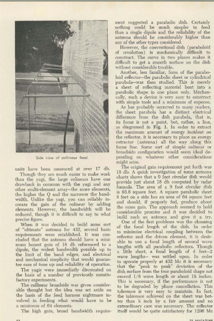
Side view of collinear feed.<br />
units have been measured at over 17 db.<br />
Though they are much easier to make work<br />
than the yagi, the large colinears have one<br />
drawback in common with the yagi and any<br />
other multi-element array-the more elements,<br />
the higher the Q and the narrower the bandwidth.<br />
Unlike the yagi, you can reliably increase<br />
the gain of the colinear by adding<br />
elements. However, the bandwidth will be<br />
reduced, though it is difficult to say to what<br />
precise figure.<br />
When it was decided to build some sort<br />
of "ultimate" antenna for 432, several basic<br />
requirements were established. It was concluded<br />
that the antenna should have a minimum<br />
honest gain of 18 db referenced to a<br />
dipole, the widest bandwidth possible up to<br />
the limit of the band edges; and electrical<br />
and mechanical simplicity that would guarantee<br />
ease of tune up and reliability of operation.<br />
The yagis were immediatly discounted on<br />
the basis of a number of previously unsatisfactory<br />
experiments.<br />
The collinear broadside was given considerable<br />
thought but the idea was set aside on<br />
the basis of the feed harness nightmare involved<br />
in feeding what would have to be<br />
a minimum of 64 elements.<br />
The high gain, broad bandwidth requirement<br />
suggested a parabolic dish. Certainly<br />
nothing could be much simpler to feed<br />
than a single dipole and the reliability of the<br />
antenna should be considerably higher than<br />
any of the other types considered.<br />
However, the conventional dish (paraboloid<br />
of revolution) is mechanically difficult to<br />
construct. The curve in two planes makes it<br />
difficult to get a smooth surface on the dish<br />
without considerable trouble.<br />
Another, less familiar, form of the paraboloid<br />
reflector-the parabolic sheet or cylindrical<br />
parabola-was then studied. This is merely<br />
a sheet of reflecting material bent into a<br />
parabolic shape in one plane only. Meehancally,<br />
such a device is very easy to construct<br />
with simple tools and a minimum of expense.<br />
As has probably occurred to many readers,<br />
the sheet parabola has a distinct electrical<br />
difference from the dish parabola, that is,<br />
its focus is not a point, but, rather, a line,<br />
as diagramed in Fig. 1. In order to extract<br />
the maximum amount of energy incident on<br />
the reflector, it is necessary to place an energy<br />
extractor (antenna) all the way along this<br />
focus line. Some sort of simple colinear or<br />
broadside configuration would seem ideal depending<br />
on whatever other considerations<br />
might arise.<br />
The original gain requirement put forth was<br />
18 db. A quick investigation of some antenna<br />
charts shows that a 9 foot circular dish would<br />
provide just about 18 db computed by radar<br />
formula. The area of a 9 foot circular dish<br />
is 63.6 square feet. A square parabolic sheet<br />
8 feet on a side has an area of 64 square feet<br />
and should, if properly fed, produce about<br />
the same gain. The approach seemed to hold<br />
considerable promise and it was decided to<br />
build such an antenna and give it a try.<br />
One of the first problems was the choosing<br />
of the focal length of the dish. In order<br />
to minimize electrical coupling between the<br />
reflector and the driven element, it is desirable<br />
to use a focal length of several wave<br />
lengths with all parabolic reflectors. Though<br />
a little short, a focal length of 4 feet-2<br />
wave lengths- was settled upon. In order<br />
to operate properly at 432 Me it is necessary<br />
that the "peak to peak" deviation of the<br />
dish surface from the true paraboloid shape not<br />
exceed 1/8 wave length or about 11> inches.<br />
This is necessary, if the performance is not<br />
to be degraded by phase cancellation. This<br />
tolerence is very easy to maintain. In fact,<br />
the tolerence achieved on the sheet was better<br />
than Jf inch by a fair amount and no<br />
extrordinary care was necessary. The reflector<br />
itself would be quite satisfactory for 1296 Me


