GF-6 Camera Crane System - Grip Factory Munich GmbH
GF-6 Camera Crane System - Grip Factory Munich GmbH
GF-6 Camera Crane System - Grip Factory Munich GmbH

Create successful ePaper yourself
Turn your PDF publications into a flip-book with our unique Google optimized e-Paper software.
<strong>Grip</strong> <strong>Factory</strong> <strong>Munich</strong><br />
YOUR INNOVATIVE PARTNER FOR CAMERA SUPPORT<br />
<strong>GF</strong>-6 <strong>Crane</strong> <strong>System</strong><br />
Instruction Manual<br />
Valid : March 2001<br />
<strong>Grip</strong> <strong>Factory</strong> <strong>Munich</strong> <strong>GmbH</strong> Tel.: +49 (0) 89 319 01 290<br />
Fürholzener Straße 1 Fax: +49 (0) 89 319 01 299<br />
85386 Eching bei München E-mail: info@g-f-m.net<br />
Germany www.g-f-m.net
Instruction Manual<br />
Contents : Page :<br />
Safety Guidelines ........................................................................... 2<br />
General assembly procedure ...........…………..........................… 3 - 4<br />
<strong>GF</strong>-6 Version 1 ( Platform ) ..................................................…....... 5<br />
<strong>GF</strong>-6 Version 2 ( Platform ) ............................................................. 6<br />
<strong>GF</strong>-6 Version 3 ( Platform ) ............................................................ 7<br />
<strong>GF</strong>-6 Version 4 ( Remote ) ........................................................…... 8<br />
<strong>GF</strong>-6 Version 5 ( Remote ) ............................................................. 9<br />
<strong>GF</strong>-6 Version 6 ( Remote ) ...................................................…....... 10<br />
<strong>GF</strong>-6 Version 6a ( Remote ) ............................................................ 11<br />
<strong>GF</strong>-6 Version 7 ( Remote ) .............................................................. 12<br />
<strong>GF</strong>-6 Version 7a ( Remote ) ............................................................ 13<br />
<strong>GF</strong>-6 Version 8 ( Remote ) .............................................................. 14<br />
Rigging system .....................................................................……... 15<br />
Balancing of crane ....................................................................…... 16<br />
General safety………. ...................................................................... 16<br />
Accessories for <strong>GF</strong>-6 crane ........................................................… 17<br />
Transport Trolley for <strong>GF</strong>-6 crane ................................................… 18<br />
Base Dolly ……………………........................................................… 19<br />
Accessories weight list.……….....................................................… 19<br />
1
SAFETY GUIDELINES :<br />
The <strong>GF</strong>-6 <strong>Crane</strong> Assembly Instructions<br />
The assembly instructions must be read and understood before set-up or operation.<br />
The <strong>GF</strong>-6 <strong>Crane</strong> may only be assembled or operated by trained and experienced personnel.<br />
The crane may only be assembled in accordance with the manufacturer’s instruction manual.<br />
The crane may not be assembled or operated under the influence of alcohol, drugs or any other<br />
intoxicating substances.<br />
The manufacturer accepts no liability for damages or injuries for incidents or accidents occurring due<br />
to negligence by the crane operator or misuse of the crane.<br />
Use of the crane on insert vehicles, camera cars or any motorised vehicle is not allowed. The<br />
manufacturer accepts no liability for damages or injuries for incidents or accidents occurring due to<br />
use of the crane on insert vehicles, camera cars or any other motorised vehicles.<br />
Only original accessories manufactured by <strong>GF</strong>M may be used with the crane.<br />
Before assembling the crane ensure that the ground surface is stable and cannot give way. When<br />
operating the crane on track, ensure that the track is level, properly laid and constructed. The correct<br />
underlay must be used to ensure that the track and underlay are secured against moving, slipping and<br />
collapse. Ensure that the underlay meets the specified support and stability requirements.<br />
The crane dolly must be level at all times. If necessary, level the crane with the provided levelling legs.<br />
Whether operating on track or on a solid ground surface it is essential that the track or surface is<br />
completely level, stable and free from obstructions.<br />
The ground surface must be stable enough to support at least 1000 kg/m2 = 2200 lbs/ sq yard.<br />
Changing weather conditions should be taken into consideration. The crane must be taken out of<br />
operation before the operational wind speed reaches 45kmh. / 28mph.<br />
The complete lift and panning range of the <strong>GF</strong>-6 <strong>Crane</strong> must be kept clear of obstructions at all times.<br />
Never operate the crane closer than 20m / 70 feet proximity to high voltage power cables.<br />
Personnel on board the crane's platform must use safety belts at all times. They should not make any<br />
sudden, abrupt movements or lean over the side of the platform. No loose objects may be stored or<br />
placed on the crane platform.<br />
Before the counterweights are removed from the bucket, ensure that the platform is resting on the<br />
ground or alternatively supported by an appropriate stable underlay. Gradually remove the<br />
counterweights before personnel leave the platform or as the case may be, the remote head or<br />
camera are removed.<br />
The manufacturers technical specifications and limits must be adhered to at all times and in no way<br />
exceeded.<br />
<strong>GF</strong>-6 <strong>Crane</strong> operation is only allowed with solid tires. <strong>Crane</strong> operation is not allowed with pneumatic<br />
wheels.<br />
A safety distance clearance of 0.50m / 1' 7" must be observed on all sides of the crane during<br />
operation.<br />
In the interest of safe crane operation abrupt, sudden movement of the crane should be avoided.<br />
2
Assembly Procedure – <strong>GF</strong>-6<br />
Before and during assembly observe the Safety Guidelines.<br />
For all versions:<br />
1. Secure the base dolly so that it cannot move or roll. Lock all wheel brakes.<br />
Move the steering rod towards the centre of the dolly or remove it so that the<br />
set-up personnel do not trip over it.<br />
Wheel<br />
brake<br />
Locked wheel brake on Base Dolly Base Dolly with mounting<br />
column and middle section<br />
2. Bolt the crane mounting column to the base dolly. Make sure that the 4 locking<br />
bolts are locked securely. (Tip: the carrying handle on the bazooka should<br />
point away from the steering end of dolly).<br />
3. Located on the middle section are 2 tilt friction locks which may be used to<br />
lock the tilt during set-up. Set the pivot arm at 90° to the centre post and lock<br />
these friction locks which can be found on the left and right hand side of the<br />
middle section.<br />
Middle section with pan and tilt lock<br />
4. Mount the middle section on the mounting column. Lock the locking screw<br />
tightly.<br />
Tip: A 12mm Allen key can be found in the mounting column’s handle to be<br />
used as a lever.<br />
3<br />
Tilt brake<br />
Pan brake
Mounting an extension arm Securing the arm with a safety pin<br />
5. Connect one of the 75cm / 2’6” sections to the middle section. Slip the<br />
connection flanges into each other and secure with the provided safety pin.<br />
Tip: To avoid the sections jamming or getting stuck make sure that the<br />
sections are joined parallel. Using a small amount of lubricant also<br />
helps. We suggest rubbing the joints with an oiled rag.<br />
6. Connect one of the angle adjusters to the end of the75cm / 2’6” section and<br />
secure it with the provided safety pin.<br />
Integrated<br />
leveller<br />
Mounting the angle adjuster Securing the rod with safety pin<br />
7. Connect one of the 75cm / 2’6” parallelogram rods to the middle section and<br />
the angle adjuster and secure it with a safety pin at each end.<br />
Tip: The angle adjuster has an integrated leveller. By turning it, the<br />
vertical plate on the angle adjuster can be set to a perfect right angle.<br />
Correct setting of the angle adjuster enhances the crane’s balance.<br />
The assembly procedure up to this point is the same in versions 1, 2, 4, 5, 6, 7.<br />
For other versions the 75cm / 2’6” extension and parallelogram are replaced by<br />
the 90cm / 3’ extension and parallelogram.<br />
To assist the set-up procedure and to reduce the risk of accidents it is<br />
recommended to use set-up support stands or rostrums.<br />
4
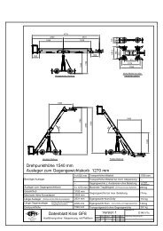
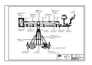
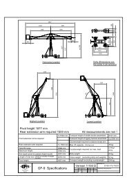
Version 1<br />
Front extension arms required 1 x 150cm / 5'<br />
Rear extension arm required 1 x 75cm / 2' 6"<br />
Maximum Euro-adapter height 320cm / 10' 8'<br />
Max. lift capacity = max 2 pers. + accessories 250kg / 550 lbs<br />
Counterweight required 27pcs = 432kg / 950lbs<br />
Lift range 332cm / 11'<br />
<strong>Crane</strong> weight (excluding dolly and weights) 139kg / 305lbs<br />
Arm reach (pivot to camera head mount) 256 cm / 8' 6"<br />
Length of rear end (pivot to outside of weight bucket) 172cm / 5' 9"<br />
Dolly weight 59kg / 129lbs<br />
Continue from point 7 on page 4 as follows;<br />
8. Connect one of the 150cm / 5’ sections to the middle section. Slip the<br />
connection flanges into each other and secure them with the provided safety<br />
pin.<br />
9. Connect the remaining angle adjuster to the end of the150cm / 5’ section and<br />
secure it with the provided safety pin.<br />
10. Connect one of the 150cm / 5’ parallelogram rods to the middle section and<br />
the angle adjuster and secure it with a safety pin at each end.<br />
Tip: The angle adjuster has an integrated leveller. By turning it, the<br />
vertical plate on the angle adjuster can be set to a perfect right angle.<br />
11. Connect the platform to the angle adjuster by inserting the male platform<br />
flange into the female flange on the angle adjuster. Secure it with the safety<br />
pin.<br />
12. Attach the weight bucket to the opposite end of the crane by inserting the male<br />
weight bucket flange into the female flange on the angle adjuster. Secure it<br />
with the safety pins at the bottom of the flange and also on the top of the angle<br />
adjuster.<br />
Before operation, all locking pins, locking screws etc should be inspected to ensure<br />
that all assembly sections are securely fastened.<br />
5
Version 2<br />
Front extension arms required 1 x 150cm / 5' + 1 x 75cm / 2' 6"<br />
Rear extension arm required 1 x 75cm / 2' 6"<br />
Maximum Euro-adapter height 390cm / 13'<br />
Max. lift capacity = max. 1 pers. + accessories 140kg / 308lbs<br />
Counterweight required 23pcs = 368kg / 809lbs<br />
Lift range 472cm / 15' 8"<br />
<strong>Crane</strong> weight (excluding dolly and weights) 149kg / 327lbs<br />
Arm reach (pivot to camera head mount) 331cm / 11'<br />
Length of rear end (pivot to outside of weight bucket) 172cm / 5' 9"<br />
Dolly weight 59kg / 129lbs<br />
Continue from point 7 on page 4 as follows;<br />
8. Connect one of the 150cm / 5’ arm sections to the middle section. Slip the<br />
connection flanges into each other and secure them with the provided safety<br />
pin.<br />
9. Connect the 75cm / 2’6” arm section to the end of the 150cm / 5’ arm section.<br />
Slip the connection flanges into each other and secure them with the provided<br />
safety pin.<br />
10. Connect the remaining angle adjuster to the end of the short section and<br />
secure it with the provided safety pin.<br />
11. Connect one of the 150cm / 5’ parallelogram rods to the middle section and a<br />
75cm / 2’6” parallelogram to the angle adjuster and secure them with safety<br />
pins at each connection.<br />
12. Connect the platform to the angle adjuster by inserting the male platform<br />
flange into the female flange on the angle adjuster. Secure it with the safety<br />
pin.<br />
Before operation, all locking pins, locking screws etc should be inspected to ensure<br />
that all assembly sections are securely fastened.<br />
6
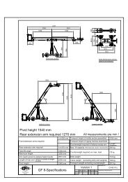
Version 3<br />
Front extension arms required 2 x 150cm / 5'<br />
Rear extension arm required 1 x 90cm / 3'<br />
Maximum Euro-adapter height 445cm / 14' 8"<br />
Max. lift capacity = max. 1 pers. + accessories 140kg / 308lbs<br />
Counterweight required 27pcs = 432kg / 950lbs<br />
Lift range 582cm / 19'5"<br />
<strong>Crane</strong> weight (excluding dolly and weights) 176kg / 387lbs<br />
Arm reach (pivot to camera head mount) 406cm / 13' 6"<br />
Length of rear end (pivot to outside of weight bucket) 187cm / 6' 3"<br />
Dolly weight 59kg / 129lbs<br />
Continue from point 7 on page 4 as follows (in this case the 90cm / 3’ section is<br />
attached to the bucket end);<br />
8. Connect one of the 150cm / 5’ arm sections to the middle section. Slip the<br />
connection flanges into each other and secure them with the provided safety<br />
pin.<br />
9. Connect another 150cm / 5’ arm section to the end of the 150cm / 5’ arm<br />
section. Slip the connection flanges into each other and secure them with the<br />
provided safety pin.<br />
10. Connect the remaining angle adjuster to the end of the 150cm / 5’ arm section<br />
and secure it with the provided safety pin.<br />
11. Connect two of the150cm / 5’ parallelogram rods to the middle section and to<br />
the angle adjuster and secure them with safety pins at each connection.<br />
12. Connect the platform to the angle adjuster by inserting the male platform<br />
flange into the female flange on the angle adjuster. Secure it with the safety<br />
pin.<br />
Note: The rigging system must be mounted. See page 15.<br />
Before operation, all locking pins, locking screws etc should be inspected to ensure<br />
that all assembly sections are securely fastened.<br />
7
Version 4<br />
Front extension arms required 2 x 150cm / 5'<br />
Rear extension arm required 1 x 75cm / 2' 6"<br />
Maximum Euro-adapter height 475cm / 15' 10"<br />
Maximum lift capacity 85kg / 187lbs<br />
Counterweight required 20pcs = 320kg / 704lbs<br />
Lift range 642cm / 21'3"<br />
<strong>Crane</strong> weight (excluding dolly and weights) 140kg / 308lbs<br />
Arm reach (pivot to camera head mount) 418cm / 13' 10"<br />
Length of rear end (pivot to outside of weight bucket) 172cm / 5' 9"<br />
Dolly weight 59kg / 129lbs<br />
Continue from point 7 on page 4 as follows;<br />
8. Connect one of the 150cm / 5’ arm sections to the middle section. Slip the<br />
connection flanges into each other and secure them with the provided safety<br />
pin.<br />
9. Connect another 150cm / 5’ arm section to the end of the first 150cm / 5’ arm<br />
section. Slip the connection flanges into each other and secure them with the<br />
provided safety pin.<br />
10. Connect the remaining angle adjuster to the end of the long arm section and<br />
secure it with the provided safety pin.<br />
11. Connect two of the 150cm / 5’ parallelogram rods to the middle section and to<br />
the angle adjuster and secure them with safety pins at each connection.<br />
12. Connect the remote bracket to the angle adjuster by inserting the male remote<br />
bracket flange into the female flange on the angle adjuster. Secure it with the<br />
safety pin.<br />
Before operation, all locking pins, locking screws etc should be inspected to ensure<br />
that all assembly sections are securely fastened.<br />
8
Version 5<br />
Front extension arms required 2 x 150cm / 5' + 1 x 75cm / 2' 6"<br />
Rear extension arm required 1 x 75cm / 2' 6"<br />
Maximum Euro-adapter height 540cm / 18'<br />
Maximum lift capacity 85kg / 187 lbs<br />
Counterweight required 23pcs = 368kg / 809lbs<br />
Lift range 772cm / 25' 8"<br />
<strong>Crane</strong> weight (excluding dolly and weights) 165kg / 363lbs<br />
Arm reach (pivot to camera head mount) 493 cm / 16' 5"<br />
Length of rear end (pivot to outside of weight bucket) 172cm / 5' 9"<br />
Dolly weight 59kg / 129lbs<br />
Continue from point 7 on page 4 as follows;<br />
8. Connect one of the 150cm / 5’ arm sections to the middle section. Slip the<br />
connection flanges into each other and secure them with the provided safety<br />
pin.<br />
9. Connect another 150cm / 5’ arm section to the end of the first 150cm / 5’ arm<br />
section. Slip the connection flanges into each other and secure them with the<br />
provided safety pin.<br />
10. Connect the 75cm / 2’6” arm section to the end of the second 150cm / 5’ arm<br />
section. Slip the connection flanges into each other and secure them with the<br />
provided safety pin.<br />
11. Connect the remaining angle adjuster to the end of the 75cm / 2’6” arm<br />
section and secure it with the provided safety pin.<br />
12. Connect two of the 150cm / 5’ parallelogram rods and 1 of the 75cm / 2’6”<br />
parallelogram rods to the middle section and to the angle adjuster and secure<br />
them with safety pins at each connection.<br />
13. Connect the remote bracket to the angle adjuster by inserting the male<br />
platform flange into the female flange on the angle adjuster. Secure it with the<br />
safety pin.<br />
Note: The rigging system must be mounted. In addition, connect the 2 parallelogram<br />
supports to the first parallelogram and first 150cm section. See page 15.<br />
Before operation, all locking pins, locking screws etc should be inspected to ensure<br />
that all assembly sections are securely fastened.<br />
9
Version 6<br />
Front extension arms required 3 x 150cm / 5'<br />
Rear extension arm required 1 x 75cm / 2' 6"<br />
Maximum Euro-adapter height 590cm / 19' 8"<br />
Maximum lift capacity 60 kg / 132lbs<br />
Counterweight required 23pcs = 368kg / 809lbs<br />
Lift range 872cm / 29'<br />
<strong>Crane</strong> weight (excluding dolly and weights) 173kg / 380lbs<br />
Arm reach (pivot to camera head mount) 568cm / 18'10"<br />
Length of rear end (pivot to outside of weight bucket) 172cm / 5' 9"<br />
Dolly weight 59kg / 129lbs<br />
Continue from point 7 on page 4 as follows;<br />
8. Connect one of the 150cm / 5’ arm sections to the middle section. Slip the<br />
connection flanges into each other and secure them with the provided safety<br />
pin.<br />
9. Connect another 150cm / 5’ arm section to the end of the first 150cm / 5’ arm<br />
section. Slip the connection flanges into each other and secure them with the<br />
provided safety pin.<br />
10. Connect the third 150cm / 5’ arm section to the end of the second 150cm / 5’<br />
arm section. Slip the connection flanges into each other and secure them with<br />
the provided safety pin.<br />
11. Connect the remaining angle adjuster to the end of the third long arm section<br />
and secure it with the provided safety pin.<br />
12. Connect 3 of the 150cm / 5’ parallelogram rods to the middle section and to<br />
the angle adjuster and secure them with safety pins at each connection.<br />
13. Connect the remote bracket to the angle adjuster by inserting the male<br />
platform flange into the female flange on the angle adjuster. Secure it with the<br />
safety pin.<br />
Note: The rigging system must be mounted. In addition, connect the 2 parallelogram<br />
supports to the second parallelogram and second 150cm section.<br />
See page 15.<br />
Before operation, all locking pins, locking screws etc should be inspected to ensure<br />
that all assembly sections are securely fastened.<br />
10
Version 6a<br />
Front extension arms required 3 x 150cm / 5'<br />
Rear extension arm required 1 x 90cm / 3'<br />
Maximum Euro-adapter height 590cm / 19' 8"<br />
Maximum lift capacity 85kg / 187lbs<br />
Counterweight required 27pcs = 432kg / 950lbs<br />
Lift range 872cm / 29'<br />
<strong>Crane</strong> weight (excluding dolly and weights) 175kg / 385lbs<br />
Arm reach (pivot to camera head mount) 568cm / 18' 10"<br />
Length of rear end (pivot to outside of weight bucket) 187cm / 6' 3"<br />
Dolly weight 59kg / 129lbs<br />
Continue from point 7 on page 4 as follows (in this case the 90cm / 3’ section is<br />
attached to the bucket end);<br />
8. Connect one of the 150cm / 5’ arm sections to the middle section. Slip the<br />
connection flanges into each other and secure them with the provided safety<br />
pin.<br />
9. Connect another 150cm / 5’ arm section to the end of the first 150cm / 5’ arm<br />
section. Slip the connection flanges into each other and secure them with the<br />
provided safety pin.<br />
10. Connect the third 150cm / 5’ arm section to the end of the second 150cm / 5’<br />
arm section. Slip the connection flanges into each other and secure them with<br />
the provided safety pin.<br />
11. Connect the remaining angle adjuster to the end of the third long arm section<br />
and secure it with the provided safety pin.<br />
12. Connect 3 of the 150cm / 5’ parallelogram rods to the middle section and to<br />
the angle adjuster and secure them with safety pins at each connection.<br />
13. Connect the remote bracket to the angle adjuster by inserting the male<br />
platform flange into the female flange on the angle adjuster. Secure it with the<br />
safety pin.<br />
Note: The rigging system must be mounted. In addition, connect the 2 parallelogram<br />
supports to the second parallelogram and second 150cm section.<br />
See page 15.<br />
Before operation, all locking pins, locking screws etc should be inspected to ensure<br />
that all assembly sections are securely fastened.<br />
11
Version 7<br />
Front extension arms required 3 x 150cm / 5' + 1 x 75cm / 2' 6"<br />
Rear extension arm required 1 x 75cm / 2' 6"<br />
Maximum Euro-adapter height 650cm / 21' 8"<br />
Maximum lift capacity 40kg / 88lbs<br />
Counterweight required 23pcs = 368kg / 809lbs<br />
Lift range 992cm / 33'<br />
<strong>Crane</strong> weight (excluding dolly and weights) 185kg / 407lbs<br />
Arm reach (pivot to camera head mount) 643cm / 21' 5"<br />
Length of rear end (pivot to outside of weight bucket) 172cm / 5' 9"<br />
Dolly weight 59kg / 129lbs<br />
Continue from point 7 on page 4 as follows;<br />
8. Connect one of the 150cm / 5’ arm sections to the middle section. Slip the<br />
connection flanges into each other and secure them with the provided safety<br />
pin.<br />
9. Connect another 150cm / 5’ arm section to the end of the first 150cm / 5’<br />
arm section. Slip the connection flanges into each other and secure them with<br />
the provided safety pin.<br />
10. Connect the third 150cm / 5’ arm section to the end of the second 150cm / 5’<br />
arm section. Slip the connection flanges into each other and secure them with<br />
the provided safety pin.<br />
11. Connect the 75cm / 2’6” arm section to the end of the third 150cm / 5’ arm<br />
section. Slip the connection flanges into each other and secure them with the<br />
provided safety pin.<br />
12. Connect the remaining angle adjuster to the end of the short arm section and<br />
secure it with the provided safety pin.<br />
13. Connect 3 of the 150cm / 5’ and 1 of the 75cm / 2’6” parallelogram rods to<br />
the middle section and to the angle adjuster and secure them with safety pins<br />
at each connection.<br />
14. Connect the remote bracket to the angle adjuster by inserting the male<br />
platform flange into the female flange on the angle adjuster. Secure it with the<br />
safety pin.<br />
Note: The rigging system must be mounted. In addition, connect the 2 parallelogram<br />
supports to the second parallelogram and second 150cm section.<br />
See page 15.<br />
Before operation, all locking pins, locking screws etc should be inspected to ensure<br />
that all assembly sections are securely fastened.<br />
12
Version 7a<br />
Front extension arms required 3 x 150cm / 5' + 1 x 75cm / 2' 6"<br />
Rear extension arm required 1 x 90cm / 3'<br />
Maximum Euro-adapter height 650cm / 21' 8"<br />
Maximum lift capacity 60kg / 132lbs<br />
Counterweight required 26pcs = 416kg / 915lbs<br />
Lift range 992cm / 33'<br />
<strong>Crane</strong> weight (excluding dolly and weights) 187kg / 411lbs<br />
Arm reach (pivot to camera head mount) 643cm / 21' 5"<br />
Length of rear end (pivot to outside of weight bucket) 187cm / 6' 3"<br />
Dolly weight 59kg / 129lbs<br />
Continue from point 7 on page 4 as follows (in this case the 90cm / 3’ section is<br />
attached to the bucket end);<br />
8. Connect one of the 150cm / 5’ arm sections to the middle section. Slip the<br />
connection flanges into each other and secure them with the provided safety<br />
pin.<br />
9. Connect another 150cm / 5’ arm section to the end of the first 150cm / 5’<br />
arm section. Slip the connection flanges into each other and secure them with<br />
the provided safety pin.<br />
10. Connect the third 150cm / 5’ arm section to the end of the second 150cm / 5’<br />
arm section. Slip the connection flanges into each other and secure them with<br />
the provided safety pin.<br />
11. Connect the 75cm / 2’6” arm section to the end of the 150cm / 5’ arm<br />
section. Slip the connection flanges into each other and secure them with the<br />
provided safety pin.<br />
12. Connect the remaining angle adjuster to the end of the short arm section and<br />
secure it with the provided safety pin.<br />
13. Connect 3 of the 150cm / 5’ and 1 of the 75cm / 2’6” parallelogram rods to<br />
the middle section and to the angle adjuster and secure them with safety pins<br />
at each connection.<br />
14. Connect the remote bracket to the angle adjuster by inserting the male<br />
platform flange into the female flange on the angle adjuster. Secure it with the<br />
safety pin.<br />
Note: The rigging system must be mounted. In addition, connect the 2 parallelogram<br />
supports to the second parallelogram and second 150cm section.<br />
See page 15.<br />
Before operation, all locking pins, locking screws etc should be inspected to ensure<br />
that all assembly sections are securely fastened.<br />
13
Version 8<br />
Front extension arms required 3 x 150cm / 5' + 2 x 75cm / 2' 6"<br />
Rear extension arm required 1 x 90cm / 3'<br />
Maximum Euro-adapter height 720cm / 24'<br />
Maximum lift capacity 40kg / 88lbs<br />
Counterweight required 26pcs = 416kg / 915lbs<br />
Lift range 1132cm / 37'8"<br />
<strong>Crane</strong> weight (excluding dolly and weights) 197kg / 433lbs<br />
Arm reach (pivot to camera head mount) 718cm / 23' 11"<br />
Length of rear end (pivot to outside of weight bucket) 187cm / 6' 3"<br />
Dolly weight 59kg / 129lbs<br />
Continue from point 7 on page 4 as follows (in this case the 90cm / 3’ section is<br />
attached to the bucket end);<br />
8. Connect one of the 150cm / 5’ arm sections to the middle section. Slip the<br />
connection flanges into each other and secure them with the provided safety<br />
pin.<br />
9. Connect another 150cm / 5’ arm section to the end of the first 150cm / 5’<br />
arm section. Slip the connection flanges into each other and secure them with<br />
the provided safety pin.<br />
10. Connect the third 150cm / 5’ arm section to the end of the second 150cm / 5’<br />
arm section. Slip the connection flanges into each other and secure them with<br />
the provided safety pin.<br />
11. Connect the 2 x 75cm / 2’6” arm sections to the end of the third 150cm / 5’<br />
arm section. Slip the connection flanges into each other and secure them with<br />
the provided safety pin.<br />
12. Connect the remaining angle adjuster to the end of the short arm section and<br />
secure it with the provided safety pin.<br />
13. Connect 3 of the 150cm / 5’ and 2 of the 75cm / 2’6” parallelogram rods to<br />
the middle section and to the angle adjuster and secure them with safety pins<br />
at each connection.<br />
14. Connect the remote bracket to the angle adjuster by inserting the male<br />
platform flange into the female flange on the angle adjuster. Secure it with the<br />
safety pin.<br />
Note: The rigging system must be mounted. In addition, connect the 2 parallelogram<br />
supports to the first parallelogram and first 150cm section and it turn connect<br />
the second set of 2 parallelogram supports to the third parallelogram and third<br />
150cm section. See page 15.<br />
Before operation, all locking pins, locking screws etc should be inspected to ensure<br />
that all assembly sections are securely fastened.<br />
14
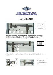
Rigging system:<br />
To enhance the rigidity of the <strong>GF</strong>-6's arm a rigging system is offered. The rigging<br />
system must be used for versions 3 and 5 through to 8. There are 4 different rod<br />
lengths ie. Very short, short, middle and long.<br />
1. Upon completion of step 7, connect the 4 sections of the rigging harness to the<br />
middle section of the <strong>GF</strong>-6. Ensure that the 8 locking bolts are fastened tightly.<br />
Rigging harness on middle section Rigging rod connected to crane arm<br />
2. Connect 4 very short rods to the turnbuckles on the rigging harness and in turn<br />
to the 4 connections on the short arm leading to the weight bucket. Hand<br />
tighten the rods by turning the turnbuckles until the 4 rods are taut.<br />
The front rigging set-up depends on the version of the <strong>GF</strong>6 which will be assembled.<br />
In this example we will take version 7.<br />
3. Connect the 4 long rods to the turnbuckles located on the rigging harness.<br />
5. Connect the middle sized rods to the respective ends of the long rods and in<br />
turn to the connection on the end of the third long arm. Hand tighten the rods<br />
by turning the turn buckles until they are taut.<br />
Parallelogram support assembly<br />
Turn-<br />
buckle<br />
Rigging<br />
harness<br />
15<br />
Parallelogram support<br />
rods should be mounted<br />
to avoid the<br />
parallelogram rods from<br />
dipping.
Balancing of the crane arm<br />
Attention : When loading the crane the maximum working load capacities /<br />
payloads must never be exceeded.<br />
After the assembly procedure has been completed the seat arms, seats, risers,<br />
camera etc may now be assembled on the platform or the remote head system may<br />
be mounted. An itemized weight list for <strong>GF</strong>M accessories may be found on page 19.<br />
Place the correct amount of counterweight in the weight bucket to balance the load.<br />
Depending on the version that has been set-up, the camera operator / operators can<br />
then take their position on the platform.<br />
Attention : The safety belts provided must be fastened upon sitting down and<br />
kept fastened at all times when on the platform.<br />
Only original <strong>GF</strong>M seats, seat arms, risers etc may be used.<br />
Working load capacity = <strong>Camera</strong> operator / operators + accessories<br />
Place the required amount of counterweights in the weight bucket so that the crane<br />
arm becomes balanced and remains in the horizontal position. If necessary, the<br />
crane can be fine balanced by adjusting the sliding weight on the rear parallelogram<br />
at the weight bucket. Do not forget to lock the sliding weight in position before tilting<br />
the arm.<br />
The counterweight bucket door must be locked when operating the crane.<br />
Deloading:<br />
Attention : The counterweights must always be gradually removed from the<br />
counterweight bucket before personnel leave the platform. When the weights<br />
are removed, the platform personnel should dismount one at a time. Extreme<br />
caution must be given to the shifting payload at all times. When dismantling<br />
the crane it is essential that the whole platform is supported fully by a stable<br />
underlay i.e. rostrum or ground surface. In any case the platform should not be<br />
in the air without support.<br />
Attention : all necessary precautions should be taken so that unauthorized third<br />
parties cannot use the crane.<br />
General Safety:<br />
Operational conditions :<br />
At a wind speed of 45km/h 30mph crane operation must be stopped and the crane<br />
secured, dismounted and the necessary safety precautions taken.<br />
If, for example, it takes 2 mins. to unload the counterweights and take the necessary<br />
precautions to secure the crane, one must commence with the procedure at a wind<br />
speed of 35km/h / 25mph. DIN15019, part 1, section 6.13.<br />
The crane may not be used in a lightening storm as there is the danger of<br />
electrocution.<br />
16
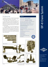
Accessories for <strong>GF</strong>- 6 crane<br />
Notice:<br />
Levelling leg Monitor carrier<br />
Push bar Track wheel with brake<br />
When operating the crane with the push bar mounted on the dolly, pay attention that<br />
the crane arm at no time collides with the push bar.<br />
The levelling legs must be removed from the base dolly before driving onto a track<br />
mounting ramp. Always use the levelling legs to level the crane when on uneven<br />
surfaces.<br />
17
Transport trolley for the <strong>GF</strong>-6 <strong>Crane</strong><br />
The above photos show the practical transport solution for the <strong>GF</strong>-6 <strong>Crane</strong> <strong>System</strong>.<br />
The <strong>GF</strong>M trolley fits the complete version 8 with dolly and column as an extra unit.<br />
18
The <strong>GF</strong>-6 Base Dolly<br />
The crane platform may be mounted on the base dolly to provide a track or western<br />
dolly style function.<br />
Insert the 3 bolts into the underside of the base, through the platform and into the<br />
turnstile mount. Lock the 3 bolts tightly<br />
Accessories for <strong>GF</strong>-6 <strong>Crane</strong> platform weight list<br />
Qty. Description Weight kg Weight lbs<br />
1 Seat arm combined 10cm / 4" AL-2210 0,75 kg 1,65 lbs<br />
1 Seat arm combined 20cm / 8" AL-2220 1,15 kg 2,53 lbs<br />
1 Seat arm combined 30cm / 12" AL-2230 1,60 kg 3,52 lbs<br />
1 Seat arm vertical 10cm / 4" AL-2211 1,25 kg 2,75 lbs<br />
1 Seat arm vertical 20cm / 8" AL-2212 1,75 kg 3,85 lbs<br />
1 Seat arm vertical 30cm / 12" AL-2213 2,20 kg 4,84 lbs<br />
1 <strong>Crane</strong> seat with seat belt AL-1030 7,20 kg 15,84 lbs<br />
1 Riser 10 cm / 4" AL-2310 2,80 kg 6,16 lbs<br />
1 Riser 20cm / 8" AL-2320 2,95 kg 6,49 lbs<br />
1 Riser 30cm / 12" AL-2330 3,40 kg 7,48 lbs<br />
1 Riser 40cm / 16" AL-2340 3,80 kg 8,36 lbs<br />
1 Riser 50cm / 20" AL-2350 4,25 kg 9,35 lbs<br />
1 Connection pin AL-2240 0,40 kg 0,88 lbs<br />
1 Ball Adapter AL-2150 2,17 kg 4,77 lbs<br />
19