BILLY GOAT MV650SPH and MV600SPE Self-Propelled Vacuum Owner’s Manual
BILLY GOAT MV650SPH and MV600SPE Self-Propelled Vacuum ...
BILLY GOAT MV650SPH and MV600SPE Self-Propelled Vacuum ...
- No tags were found...

Create successful ePaper yourself
Turn your PDF publications into a flip-book with our unique Google optimized e-Paper software.
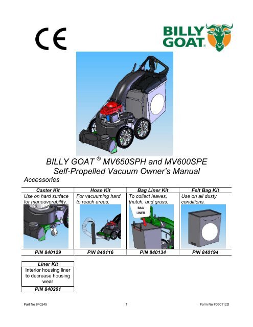
<strong>BILLY</strong> <strong>GOAT</strong> ® <strong>MV650SPH</strong> <strong>and</strong> <strong>MV600SPE</strong><br />
<strong>Self</strong>-<strong>Propelled</strong> <strong>Vacuum</strong> <strong>Owner’s</strong> <strong>Manual</strong><br />
Accessories<br />
Caster Kit Hose Kit Bag Liner Kit Felt Bag Kit<br />
Use on hard surface For vacuuming hard To collect leaves, Use on all dusty<br />
for maneuverability. to reach areas. thatch, <strong>and</strong> grass. conditions.<br />
P/N 840129 P/N 840116 P/N 840134 P/N 840194<br />
Liner Kit<br />
Interior housing liner<br />
to decrease housing<br />
wear<br />
P/N 840201<br />
Part No 840245 1 Form No F050112D
<strong>MV650SPH</strong> <strong>Self</strong>-<strong>Propelled</strong> <strong>Vacuum</strong> <strong>Owner’s</strong> <strong>Manual</strong><br />
CONTENTS<br />
Specifications <strong>and</strong> Sound/Vibration ................................................................................................................... 3<br />
Instruction Labels ............................................................................................................................................... 4<br />
Assembly Instructions ........................................................................................................................................ 5-8<br />
Operation ........................................................................................................................................................... 9-13<br />
Maintenance <strong>and</strong> Troubleshooting ..................................................................................................................... 14-19<br />
Illustrated Parts List ........................................................................................................................................... 20-27<br />
Go to http://www.billygoat.com for French-Canadian translations of the product manuals.<br />
Visitez http://www.billygoat.com pour la version canadienne-française des manuels de produits<br />
Part No 840245 2 Form No F050112D
<strong>MV650SPH</strong> <strong>Self</strong>-<strong>Propelled</strong> <strong>Vacuum</strong> <strong>Owner’s</strong> <strong>Manual</strong><br />
MV 650 SERIES SPECIFICATIONS<br />
<strong>MV650SPH</strong><br />
<strong>MV600SPE</strong><br />
Engine Type Honda GSV190AA1A Briggs <strong>and</strong> Stratton 122MO70110F1<br />
Horsepower 6.5 (4.85 kW) 6.25 (4.66 kW)<br />
Fuel Capacity 1.6 qt (1.5 L) 1qt (.9L)<br />
Oil Capacity 0.58 qt (0.54L) 0.63 qt (0.59L)<br />
Unit Weight 179 lbs (81.2 kg) 179 lbs (81.2 kg)<br />
Shipping Weight 208 lbs (94.3 kg) 208 lbs (94.3 kg)<br />
Overall Dimensions 28” Wide x 62.5” Long x 45.5” High 28” Wide x 62.5” Long x 45.5” High<br />
Maximum Operating Slope 20 o 20 o<br />
In compliance with 2000/14/EEC<br />
st<strong>and</strong>ards<br />
103 dB(a) at 3320 rpm 103 dB(a) at 3320 rpm<br />
Sound at operators ear 83 dB(a) at 3320 rpm 83 dB(a) at 3320 rpm<br />
SOUND DATA<br />
SOUND LEVEL 103 Dba at Operator Position<br />
Sound tests were conducted in accordance with 2000/14/EC as well as ISO11094, <strong>and</strong> were performed on 5-17-2005 under the conditions listed<br />
below.<br />
Sound power level listed is the highest value for any model covered in this manual. Please refer to serial plate on the unit<br />
for the sound power level for your model.<br />
General Conditions:<br />
Sunny<br />
Temperature: 66.2 o F (19 o C)<br />
Wind Speed:<br />
8.5 mph (13.7kph)<br />
Wind Direction:<br />
South Southwest<br />
Humidity: 59%<br />
Barometric Pressure:<br />
29.9” Hg (101.35kPa)<br />
VIBRATION DATA<br />
VIBRATION LEVEL 1.43g(14.00m/s 2)<br />
Vibration levels at the operator’s h<strong>and</strong>les were measured in the vertical, lateral <strong>and</strong> longitudinal directions using calibrated vibration test<br />
equipment. Tests were performed on 5-24-2006 under the conditions listed below.<br />
General Conditions:<br />
Sunny<br />
Temperature: 73.7 o F (23.2 o C)<br />
Wind Speed:<br />
8.05 mph (3.6m/s)<br />
Wind Direction:<br />
South<br />
Humidity: 83.5%<br />
Barometric Pressure:<br />
29.91” Hg (101.31 kPa)<br />
Form No F050112D 3 Part No 840245
<strong>MV650SPH</strong> <strong>Self</strong>-<strong>Propelled</strong> <strong>Vacuum</strong> <strong>Owner’s</strong> <strong>Manual</strong><br />
INSTRUCTION LABELS<br />
The labels shown below were installed on your <strong>BILLY</strong> <strong>GOAT</strong> ® MV <strong>Vacuum</strong>. If any labels are damaged or missing,<br />
replace them before operating this equipment. Item numbers from the Illustrated Parts List <strong>and</strong> part numbers are<br />
provided for convenience in ordering replacement labels. The correct position for each label may be determined by<br />
referring to the Figure <strong>and</strong> Item numbers shown.<br />
PN 400268<br />
(See Figure 3 Item 55)<br />
PN 890254<br />
(See Figure 4 Item 162)<br />
PN 840054<br />
(See Figure 1 Item 34)<br />
PN 400424<br />
(See Figure 1 Item 11)<br />
PN 810736<br />
(See Figure 4 Item 174)<br />
PN 890301<br />
(See Figure 4 Item 163)<br />
PN 900327<br />
(See Figure 2 Item 118)<br />
PN 840080<br />
(See Figure 4 Item 175)<br />
PN 500176<br />
(See Figure 2 Item 120)<br />
ENGINE LABELS<br />
CONTROLS<br />
HONDA<br />
Throttle<br />
Drive<br />
P/N 840045 P/N 510127<br />
Part No 840245 4 Form No F050112D
<strong>MV650SPH</strong> <strong>Self</strong>-<strong>Propelled</strong> <strong>Vacuum</strong> <strong>Owner’s</strong> <strong>Manual</strong><br />
PARTS LIST<br />
Part No 840245 6 Form No F050112D
<strong>MV650SPH</strong> <strong>Self</strong>-<strong>Propelled</strong> <strong>Vacuum</strong> <strong>Owner’s</strong> <strong>Manual</strong><br />
ASSEMBLY INSTRUCTIONS<br />
Your <strong>BILLY</strong> <strong>GOAT</strong> ® MV <strong>Vacuum</strong> was shipped in one carton, completely assembled except for the Hood/Upper<br />
H<strong>and</strong>le Assembly. Mounting hardware for the Hood/Upper H<strong>and</strong>le Assembly is temporarily installed on the lower<br />
h<strong>and</strong>le <strong>and</strong> the Housing assembly.<br />
READ all safety instructions before assembling unit.<br />
TAKE CAUTION when removing the unit from the box since Hood/Upper H<strong>and</strong>le Assembly is<br />
attached to the unit by cables.<br />
Remove unit from carton. Make sure the following items that have been packed with unit:<br />
Parts bag P/N 840187<br />
<strong>Owner’s</strong> <strong>Manual</strong>, P/N 840245<br />
General Safety <strong>and</strong> Warnings <strong>Manual</strong>, P/N 100294<br />
Declaration of Conformity, P/N 840204<br />
Honda Engine <strong>Manual</strong><br />
Warranty Card, P/N 400972<br />
Ty-Wraps (2 ea)<br />
Hardware Bag<br />
DISCONNECT spark plug wire before assembling unit.<br />
1. Attach hood assembly to the housing then hold in place<br />
during the step 2.<br />
NOTE: BE SURE ALL CABLES ARE ROUTED ON THE<br />
UNDERSIDE OF THE HOOD AND HOUSING.<br />
2. Install item #170 center bolt first when aligned with<br />
a nut on the housing.<br />
3. Attach rest of hood assembly to the housing using<br />
corresponding hardware.<br />
NOTE: You will have to insert the bolt/washer from<br />
the inside by reaching through the hood.<br />
1st<br />
- Two 7/16” wrenches.<br />
Form No F050112D 7 Part No 840245
<strong>MV650SPH</strong> <strong>Self</strong>-<strong>Propelled</strong> <strong>Vacuum</strong> <strong>Owner’s</strong> <strong>Manual</strong><br />
4. Attach upper h<strong>and</strong>le brace to lower h<strong>and</strong>le using<br />
corresponding hardware. Then repeat this step on the<br />
other side.<br />
5. Attach rod end (164) to the nozzle door rod then<br />
secure in place by tightening jam nut.<br />
6. Attach nozzle door rod to the nozzle door using<br />
corresponding hardware.<br />
NOTE: It is easier to do this with nozzle door closed.<br />
- Two 1/2” wrenches.<br />
- Two 9/16” wrenches.<br />
7. Attach rod end to rod (as in step 5).<br />
8. Attach nozzle door rod to the lever with<br />
nozzle door closed <strong>and</strong> lever in hose kit<br />
position.<br />
NOTE: Check to see nozzle door open <strong>and</strong><br />
close all the way (see page 15). Tighten or<br />
loosen the rod end (164) for any<br />
adjustments.<br />
9. Install cable ty wraps. 10. Reconnect spark plug<br />
wire.<br />
HERE<br />
11. Attach the bag.<br />
Two 9/16”<br />
wrenches.<br />
HERE<br />
Part No 840245 8 Form No F050112D
<strong>MV650SPH</strong> <strong>Self</strong>-<strong>Propelled</strong> <strong>Vacuum</strong> <strong>Owner’s</strong> <strong>Manual</strong><br />
OPERATION<br />
OPERATOR CONTROLS<br />
The operator’s position is at the rear of the machine between the h<strong>and</strong>lebars. The operator should STAND in a position to allow<br />
both h<strong>and</strong>lebars to be grasped firmly, which allows sufficient leverage to steer the machine. Operator’s controls are shown below.<br />
3<br />
4<br />
1<br />
6<br />
5<br />
2<br />
Operator Control Locations<br />
STARTING<br />
1 Drive Clutch Lever 4 Throttle Control<br />
2 Bag Latch 5 Drive Shifter Control<br />
3 Pull Starter 6 Nozzle Door Adjuster<br />
CHECK engine oil level before operating machine.<br />
1. Place equipment on a level, firm surface that is free of rocks or other debris.<br />
2. Place throttle in START position.<br />
Throttle<br />
DO NOT START equipment without the debris bag in place.<br />
Form No F050112D 9 Part No 840245
<strong>MV650SPH</strong> <strong>Self</strong>-<strong>Propelled</strong> <strong>Vacuum</strong> <strong>Owner’s</strong> <strong>Manual</strong><br />
3. Secure the unit with left h<strong>and</strong> at the h<strong>and</strong>le then pull starter rope with right h<strong>and</strong> to start engine.<br />
On Electric<br />
models only<br />
PULL ROPE<br />
STARTER WITH<br />
RIGHT HAND<br />
SECURE UNIT AT<br />
THE HANDLE<br />
WITH LEFT HAND<br />
DURING START<br />
PULL STARTER CORD slowly until resistance is felt. Then pull cord rapidly to avoid kickback.<br />
4. Move throttle control back to FAST position <strong>and</strong> allow engine to reach correct operating speed.<br />
5. For Electric models: Set the throttle to the fast position, then pull up <strong>and</strong> push forward on the start switch.<br />
Choke if needed<br />
VACUUM NOZZLE HEIGHT ADJUSTMENT<br />
FOR MAXIMUM PICKUP: Adjust nozzle height as close to debris as possible, but without blocking airflow into the nozzle. NOTE:<br />
Never bury nozzle into debris. The vacuum nozzle is raised <strong>and</strong> lowered by turning the crank h<strong>and</strong>le clockwise <strong>and</strong> counterclockwise.<br />
Part No 840245 10 Form No F050112D
<strong>MV650SPH</strong> <strong>Self</strong>-<strong>Propelled</strong> <strong>Vacuum</strong> <strong>Owner’s</strong> <strong>Manual</strong><br />
VACUUM NOZZLE DOOR ADJUSTMENT<br />
The vacuum nozzle door adjusts for the maximum performance under various applications.<br />
Nozzle fully opened. This is ideal for turf application<br />
Nozzle half way opened. This is ideal for hard surface application<br />
Nozzle closed for OPTIONAL hose kit. This is ideal for hard to reach places.<br />
Form No F050112D 11 Part No 840245
<strong>MV650SPH</strong> <strong>Self</strong>-<strong>Propelled</strong> <strong>Vacuum</strong> <strong>Owner’s</strong> <strong>Manual</strong><br />
VACUUMING OPERATION<br />
1. Move Shift Lever to correct position (1, 2, or 3) for desired gear.<br />
Gear Shift Lever<br />
2. Squeeze the Drive Clutch lever against the h<strong>and</strong>le to engage the drive.<br />
Drive Clutch Lever<br />
SHUT DOWN<br />
1. Release Drive Clutch Lever to disengage the drive.<br />
2. Pull Throttle Control all the way back to the STOP position.<br />
Part No 840245 12 Form No F050112D
<strong>MV650SPH</strong> <strong>Self</strong>-<strong>Propelled</strong> <strong>Vacuum</strong> <strong>Owner’s</strong> <strong>Manual</strong><br />
CLEARING A CLOGGED NOZZLE<br />
DISCONNECT spark plug wire before servicing unit.<br />
1. Shut engine off <strong>and</strong> wait for impeller to stop completely.<br />
2. Disconnect spark plug wire.<br />
3. Wearing durable gloves, remove clog.<br />
WEAR durable gloves. Clog may contain sharp materials.<br />
4. Reconnect spark plug wire.<br />
DEBRIS BAG<br />
Debris bags are normal replaceable wear items.<br />
Frequently empty debris to prevent bag overloading with more weight than you can lift.<br />
Bag liners are available for use in various conditions where debris will be vacuumed. (see Bag Liner Options shown<br />
on page 1).<br />
DO NOT place bag on or near hot surface, such as engine.<br />
Be sure engine has come to a complete stop before removing or emptying bag!!.<br />
This vacuum is designed for picking up trash, organic material <strong>and</strong> other similar debris (see Safety Warnings<br />
page 4-5).<br />
Many vacuums are used where dust is mixed with trash. Your unit can intermittently vacuum in dusty areas.<br />
However, following these rules will help maintain your machine's ability to vacuum in dusty conditions:<br />
•Run machine at idle to quarter throttle.<br />
•Machine or pressure-wash debris bag if normal cleaning does not fully clean bag. Bag should be thoroughly dry<br />
before use.<br />
Having one or more spare Felt Filter (840194) is a good way to reduce down time while dirty bags are being<br />
cleaned.<br />
Form No F050112D 13 Part No 840245
<strong>MV650SPH</strong> <strong>Self</strong>-<strong>Propelled</strong> <strong>Vacuum</strong> <strong>Owner’s</strong> <strong>Manual</strong><br />
MAINTENANCE<br />
PERIODIC MAINTENANCE<br />
Periodic maintenance should be performed at the following intervals:<br />
Maintenance Operation<br />
Every<br />
Use<br />
Daily or Every<br />
5 Hours<br />
Every 25<br />
Hours<br />
Every 50<br />
Hours<br />
Every 100-150<br />
Hours<br />
Inspect for worn or damaged parts.<br />
•<br />
Check for excessive vibration<br />
•<br />
Inspect for loose parts.<br />
•<br />
Clean Debris Bag<br />
•<br />
Lubricate clutch control lever (Use white lithium grease or equiv.)<br />
LOCATION 1<br />
•<br />
Lubricate height adjuster LOCATION 2<br />
•<br />
Check drive clutch cable tension.<br />
•<br />
Replace drive belts.<br />
•<br />
COMMON REPLACEMENT PARTS<br />
<br />
<br />
Bag. P/N 840189. Original equipment replacement bag.<br />
Skid. P/N 840041. Nozzle wear guard skid.<br />
Drive Belt P/N 840066, Original equipment replacement belt<br />
LOCATION 1 LOCATION 2<br />
HERE<br />
HERE<br />
Apply lubricant on the zinc die cast barrel.<br />
Apply lubricant on the thread.<br />
Part No 840245 14 Form No F050112D
<strong>MV650SPH</strong> <strong>Self</strong>-<strong>Propelled</strong> <strong>Vacuum</strong> <strong>Owner’s</strong> <strong>Manual</strong><br />
IMPELLER REMOVAL<br />
READ all safety instructions before servicing unit.<br />
DISCONNECT spark plug wire before servicing unit.<br />
Tools required:<br />
- 1/2” socket, 3/8” drive<br />
- ratchet, 3/8”<br />
- drive extension, 3/8” drive<br />
- universal joint, 3/8” drive<br />
- pry bar or long screwdriver<br />
- jack st<strong>and</strong>s or similar device adequate to support weight of machine.<br />
1. Wait for engine to cool <strong>and</strong> disconnect spark plug.<br />
2. Drain fuel <strong>and</strong> oil from the engine.<br />
3. Remove belt cover by removing 5 screws.<br />
4. Detach drive belt from the transmission pulley by rotating the transmission assembly to relieve belt tension.<br />
5. Remove engine, impeller <strong>and</strong> mounting plate by removing bolts around outside of housing.<br />
6. Leaving engine fastened to plate, remove impeller bolt <strong>and</strong> lock washer <strong>and</strong> slide impeller off crankshaft ( A<br />
puller may be required). CAUTION: Do not drop impeller.<br />
7. If impeller does not slide off crankshaft, place two crowbars between impeller <strong>and</strong> housing on opposite<br />
sides. Pry impeller away from engine until it loosens. Using a penetrating oil can help loosen a stuck<br />
impeller.<br />
8. If the impeller cannot be loosened, obtain a 1” (25.4mm) longer bolt of the same diameter <strong>and</strong> thread type as<br />
the impeller bolt. Invert engine <strong>and</strong> impeller <strong>and</strong> support engine above ground to prevent recoil damage.<br />
Thread longer bolt by h<strong>and</strong> into the crankshaft until bolt bottoms. Using a suitable gear or wheel puller<br />
against the bolt head <strong>and</strong> the impeller back-plate (near the blades), remove impeller from shaft.<br />
9. To reinstall impeller, use a new impeller bolt <strong>and</strong> lockwasher<br />
10. Tighten impeller bolt. Torque impeller bolt to 33-38 Ft. Lbs. (45-52 N.m).<br />
11. Reinstall engine, impeller, <strong>and</strong> mounting plate onto housing in reverse order of removal.<br />
12. Before connecting spark plug wire, slowly pull engine starting rope to insure that impeller rotates freely.<br />
13. Reconnect spark plug wire.<br />
DRIVE CLUTCH CABLE ADJUSTMENT<br />
READ all safety instructions before servicing unit.<br />
DISCONNECT spark plug wire before servicing unit.<br />
Tools required:<br />
- Ratchet wrench with 6” extension <strong>and</strong> 3/8” socket.<br />
- Two 10mm open end wrenches.<br />
- Tape measure.<br />
Form No F050112D 15 Part No 840245
<strong>MV650SPH</strong> <strong>Self</strong>-<strong>Propelled</strong> <strong>Vacuum</strong> <strong>Owner’s</strong> <strong>Manual</strong><br />
Procedure:<br />
1. Wait for engine to cool <strong>and</strong> DISCONNECT SPARK PLUG!<br />
2. Engage the clutch lever then pull the unit back until it stops freewheeling. The clutch lever should engage<br />
around 2 5/16” of travel or 4 inches from tip of lever to h<strong>and</strong>le.<br />
3. Tighten or loosen cable adjuster nut next to the clutch lever until drive engages at 4” from h<strong>and</strong>le.<br />
4. Holding the adjuster nut in place with one wrench tighten cable lock nut firmly.<br />
5. Readjust as needed.<br />
6. RECONNECT SPARK PLUG!<br />
7. Test run unit to insure proper operation after this or any other maintenance procedure.<br />
8. If clutch still will not engage at 4” from h<strong>and</strong>le, remove guard retaining screws <strong>and</strong> guard.<br />
9. Measure the amount of spring stretch. Spring should measure 1 1/8” when engaged (Lever 4” from h<strong>and</strong>le).<br />
10. Release clutch lever <strong>and</strong> then move it to engagement position again <strong>and</strong> hold it, check the spring length to<br />
assure it stayed in adjustment.<br />
11. Re-install guard <strong>and</strong> fasteners.<br />
INCREASE<br />
1 1/8"<br />
DRIVE BELT REMOVAL AND REPLACEMENT<br />
READ all safety instructions before servicing unit.<br />
cable adjustment<br />
2 1/16”<br />
4"<br />
from<br />
h<strong>and</strong>le<br />
Loosen<br />
Tighten<br />
DISCONNECT spark plug wire before servicing unit.<br />
Tools required:<br />
- 3/8” drive ratchet<br />
- 3/8” <strong>and</strong> ½” socket wrenches<br />
- 3/8” <strong>and</strong> 5/16” wrench<br />
Procedure:<br />
1. Wait for engine to cool completely <strong>and</strong> DISCONNECT SPARK PLUG.<br />
2. Remove guard fasteners <strong>and</strong> guard.<br />
3. Remove throttle control cable from engine.<br />
4. Unplug wiring harness wire at engine.<br />
5. Tilt transmission input pulley toward engine <strong>and</strong> remove the belt from it upward.<br />
6. Remove all six screws fastening the engine base plate to the housing.<br />
7. Lift engine assembly from housing.<br />
8. Slide belt inward under the engine <strong>and</strong> off downward around impeller.<br />
9. Install new belt in reverse order of belt removal.<br />
10. Note: before placing new belt on transmission pulley look under the engine to insure the belt is properly in<br />
the groove of the engine pulley.<br />
11. Install engine assembly in reverse order of removal.<br />
12. RECONNECT THE SPARK PLUG<br />
Part No 840245 16 Form No F050112D
<strong>MV650SPH</strong> <strong>Self</strong>-<strong>Propelled</strong> <strong>Vacuum</strong> <strong>Owner’s</strong> <strong>Manual</strong><br />
INSTALLING NEW DRIVE CHAIN/ALIGNMENT/TENSION<br />
READ all safety instructions before servicing unit.<br />
DISCONNECT spark plug wire before servicing unit.<br />
Tools required:<br />
- 7/16” <strong>and</strong> 1/2” socket.<br />
- 7/16” <strong>and</strong> 1/2” combination wrench.<br />
- “Needle nose” pliers<br />
- Flat head screwdriver<br />
Allow the engine to cool completely <strong>and</strong> DISCONNECT THE SPARK PLUG.<br />
1. Unfasten <strong>and</strong> remove the guard.<br />
2. Rotate left rear wheel to bring the chain “master link” into view on the axle<br />
sprocket.<br />
3. Using the needle nose pliers carefully remove master link retaining spring<br />
clip.<br />
4. Slide the master link from the chain <strong>and</strong> remove the chain.<br />
5. Thread the new chain onto the sprockets, place the ends of the chain on the<br />
axle sprocket, this makes it easier to hold the chain in place when you slide<br />
the new master link in place.<br />
6. Install the new master link <strong>and</strong> CAREFULLY install the retaining clip.<br />
7. Rotate left rear wheel to find the location where the chain is tightest (there<br />
are always slight variations in the sprockets that make the chain tighter at<br />
places in its rotation).<br />
8. Rotate the axle several times <strong>and</strong> listen for “popping” or “clacking” this<br />
indicates too much tension on the chain or misalignment of the chain. Skip<br />
to Step 12 if no “popping” or “crackling” occurs.<br />
Improper Chain Tension<br />
9. At the point where the chain is tightest check the chain to for ¼” to ½” total<br />
slack halfway between the axle sprocket <strong>and</strong> the transmission sprocket.<br />
Skip to Step 11 if the deflection is correct.<br />
10. Loosen 4 nuts holding the bearing bracket (see Fig 1) slide it very slightly<br />
forward to tighten the chain or slide backward to loosen. Tighten 4 nuts<br />
back then check the chain deflection. Repeat this step if necessary.<br />
Improper Chain Alignment<br />
11. Loosen 5 bolts securing the drive system (see Fig 2) slide it left or right<br />
then check the alignment using straight edge. Tighten 5 bolts then repeat<br />
Step 8.<br />
12. Reinstall the guard <strong>and</strong> all of its fasteners.<br />
13. RECONNECT THE SPARK PLUG.<br />
Fig 1<br />
Fig 2<br />
Form No F050112D 17 Part No 840245
<strong>MV650SPH</strong> <strong>Self</strong>-<strong>Propelled</strong> <strong>Vacuum</strong> <strong>Owner’s</strong> <strong>Manual</strong><br />
WIRING DIAGRAMS<br />
Bag Switch Circuit Schematic Diagram<br />
Battery Care (For Electric-Starting Models)<br />
Proper care can extend the life of a battery. Follow these recommendations to ensure your battery’s best<br />
performance <strong>and</strong> long life:<br />
• Do not allow the battery charge to get too low. If the machine is not used, charge the battery every 4 – 6<br />
weeks. Operate the engine for at least 45 minutes to maintain proper battery charge.<br />
• Store an unused battery in a dry area that does not freeze.<br />
• Do not charge an already charged battery. In theory, you cannot overcharge our battery with a trickle<br />
charger; however, when a battery is fully charged <strong>and</strong> the charger is still on, it generates heat that could<br />
be harmful to the battery. A fully charged battery will read 12V-13.2V with a voltmeter.<br />
• Do not continue to crank your engine when the battery charge is low.<br />
Charging the Battery<br />
Operate the engine for at least 45 minutes to maintain proper battery charge. If the battery loses its<br />
charge, you will need to use a trickle charger to recharge it. Caution: The charger should have an output<br />
of 12 volts at no more than 2 amps. Using a charger with higher amps will cause significant damage to the<br />
battery.<br />
• At 1 amp, the battery may need charging for as long as 48 hours.<br />
• At 2 amps, the battery may need charging for as long as 24 hours.<br />
NOTE: Using the Recoil Starter <strong>and</strong> then running the engine will not recharge a dead or significantly<br />
discharged battery.<br />
WHEN YOU ARE FINISHED CHARGING THE BATTERY, DISCONNECT THE CHARGER FROM THE<br />
OUTLET FIRST, THEN DISCONNECT THE BATTERY CHARGER WIRES FROM THE BATTERY. IF<br />
YOU LEAVE THE BATTERY CHARGER WIRES CONNECTED TO THE BATTERY, THE BATTERY<br />
WILL DISCHARGE ITSELF BACK INTO THE CHARGER.<br />
Part No 840245 18 Form No F050112D
<strong>MV650SPH</strong> <strong>Self</strong>-<strong>Propelled</strong> <strong>Vacuum</strong> <strong>Owner’s</strong> <strong>Manual</strong><br />
TROUBLESHOOTING<br />
Problem Possible Cause Solution<br />
Will not vacuum or has poor vacuum<br />
performance.<br />
· Dirty or full debris bag or filter. · Clean debris bag <strong>and</strong> filter. Shake bag clean or<br />
wash.<br />
· Nozzle height set too high or too low. · Adjust nozzle height (see page 14).<br />
· Hose kit cap missing. · Check for hose kit cap.<br />
· Clogged nozzle or exhaust. · Unclog nozzle or exhaust (see page 5)<br />
· Excessive quantity of debris. · Allow air to feed with debris.<br />
Abnormal vibration. · Loose or out of balance impeller. · Check impeller <strong>and</strong> replace if required.<br />
· Loose engine. · Check engine.<br />
Engine will not start. · Throttle in off position. · Check throttle control (see page 13).<br />
· Engine not in full choke position. · Check throttle, choke position (see page 13).<br />
· Out of gasoline or bad, old gasoline. · Check gasoline.<br />
· Spark Plug wire disconnected. · Connect spark plug wire.<br />
· Gas valve off. · Turn on gas valve.<br />
· Dirty air cleaner. · Clean or replace air cleaner. Contact a qualified<br />
service person.<br />
· Safety Interlock disengaged on bag plate. · Latch the bag properly or check the bag rod to<br />
see if it is bent.<br />
Engine is locked, will not pull over. · Impeller plugged or clogged. · Remove debris (see page 16).<br />
· Engine problem. · Contact an engine servicing dealer for engine<br />
problems.<br />
No self-propelling · Drive clutch not engaged · Engage the drive clutch lever.<br />
· Transmission not in gear. · Check transmission shift control (see page 16).<br />
· Drive belt worn or broken · Check the drive belt.<br />
· Drive clutch cable out of adjustment or broken. · Check the drive clutch cable (see page 20).<br />
· Spring tension too loose · Check spring legnth (see page 20).<br />
· Drive chain off the sprocket. · Check the drive chain (see page 22).<br />
<strong>Self</strong> propelled drive will not release · Improper drive clutch cable adjustment or · Check the drive clutch cable (see page 20).<br />
cable is kinked.<br />
Noisy or broken chain · No chain lubrication. · Lubricate chain.<br />
· Chain misalignment or tension. · Check the drive chain (see page 22).<br />
Form No F050112D 19 Part No 840245
<strong>MV650SPH</strong> <strong>Self</strong>-<strong>Propelled</strong> <strong>Vacuum</strong> <strong>Owner’s</strong> <strong>Manual</strong><br />
ILLUSTRATED PARTS LIST<br />
Nozzle Assembly<br />
Figure 1<br />
Part No 840245 20 Form No F050112D
<strong>MV650SPH</strong> <strong>Self</strong>-<strong>Propelled</strong> <strong>Vacuum</strong> <strong>Owner’s</strong> <strong>Manual</strong><br />
Nozzle Assembly Parts List<br />
PART<br />
<strong>MV650SPH</strong> <strong>MV600SPE</strong><br />
ITEM NO. NUMBER DESCRIPTION<br />
QTY. QTY.<br />
1 350127 YOKE 1/2 - 20 1 1<br />
2 350128 PIN YOKE 1/2" 1 1<br />
3 840243 SCREWCAP BUTTON HEAD 3/8"-16 X 1 1/4" PL 2 2<br />
4 8172009 WASHER 3/8" SAE ZP 2 2<br />
5 8161042 NUT LOCK 3/8-16 LT WT THIN ZP 2 2<br />
6 8041038 SCREWCAP 5/16 -18 x 3 1/2 1 1<br />
7 8160002 NYLON INSERT LOCKNUT 5/16-18 UNC 3 3<br />
8 8172020 WASHER FLAT FENDER 5/16 1 1<br />
9 8161044 NYLON INSERT LOCKNUT 1/2-13 UNC THIN 2 2<br />
10 8171002 WASHER 1/4" FC ZP 3 3<br />
11 400424 LABEL WARNING OPEI 1 1<br />
12 8024050 BOLTCARRIAGE 5\16-18X3 1\2 2 2<br />
13 520156 ROLL PIN 1/4 X 1 LONG 2 2<br />
14 8172011 WASHER 1/2" SAE ZP 2 2<br />
15 840118 NOZZLE MV VAC ASSEMBLY 1 1<br />
16 840019 CAP 5 IN HOSE VAC 1 1<br />
17 840024 HANDLE LOWER MV VAC 1 1<br />
18 840101 WHEEL 14" ASSEMBLY WITH BEARING AND TIRE 2 2<br />
19 840104 AXLE FRONT WA MV VAC 1 1<br />
20 840155 BRACKET HGT ADJ WA W/LABEL MV VAC 1 1<br />
21 8041004 SCREWCAP 1/4 - 20 x 0.75 HWH 1 3<br />
22 840034 LINK HGT ADJ MV VAC 1 1<br />
23 840041 BRACKET NOZZLE WEAR GUARD MV VAC 2 2<br />
24 840029 ROD CONNECT HGT ADJ 1 1<br />
25 840073 BUSHING 0.5" ID 0.625 OD X X 0.250 1 1<br />
26 840119 ROD HANDLE CRANK ASSEMBLY 1 1<br />
27 840057 HANDLE CRANK 0.5 ID X 3.72 LONG 1 1<br />
28 840078 BUSHING 3/8" ID 1/2" OD X 3/8" LONG 2 2<br />
29 840158 WASHER LOCK 1/4" TWISTED TOOTH 1 1<br />
30 840207 NUT PAL 0.5" ID x 0.75 OD 2 2<br />
31 840135 NOZZLE COVER MV VAC 1 1<br />
32 840055 LABEL PRODUCT DECAL MV 1 1<br />
33 840035 SCREW PLASTIC 5/8 8 8<br />
34 840054 LABEL HGT ADJ MV VAC 1 1<br />
35 8122082 SCREW SELF-TAP 5/16 NC X 3/4 HEX 2 4<br />
36 840088 BRACKET NOZZLE COVER REINFORMENT MV 1 1<br />
37 8024021 BOLT CARRIAGE 1/4-20X0.75 3 3<br />
38 900455 NUT FLANGE 1/4-20 3 3<br />
100 8172007 WASHER 1/4" SAE ZP - 4<br />
195 840017 MV WHEEL BEARING 2 2<br />
201 840117 SOLENOID ELEC START - 1<br />
202 840198 BRACKET SOLENOID MOUNT MV - 1<br />
209 8181007 WASHER LOCK 1/4" EXT TOOTH - 2<br />
211 8142001 NUT 1/4" FIN HEX ZP - 2<br />
Form No F050112D 21 Part No 840245
<strong>MV650SPH</strong> <strong>Self</strong>-<strong>Propelled</strong> <strong>Vacuum</strong> <strong>Owner’s</strong> <strong>Manual</strong><br />
Drive /Rear Axle Assembly<br />
Figure 2<br />
Part No 840245 22 Form No F050112D
<strong>MV650SPH</strong> <strong>Self</strong>-<strong>Propelled</strong> <strong>Vacuum</strong> <strong>Owner’s</strong> <strong>Manual</strong><br />
Drive /Rear Axle Assembly Parts List<br />
PART<br />
<strong>MV650SPH</strong> <strong>MV600SPE</strong><br />
ITEM NO. NUMBER DESCRIPTION<br />
QTY. QTY.<br />
80 840110 BRACKET TRANS MOUNT WA MV VAC 1 1<br />
81 350133 BEARING 3/4" W/PILLOW BLOCK 2 2<br />
82 840009 DIFFERENTIAL 54 TOOTH D-CUT 1 1<br />
83 840086 BRACKET TRANS ANTI ROTATION MV 1 1<br />
84 840010 GUARD DRIVE SP VAC 1 1<br />
85 840085 TRANSMISSION 3 SPD GENERAL TRANS. 1 1<br />
86 510126 SPROCKET 8 TOOTH 1 1<br />
87 840066 BELT 3L34 1 1<br />
88 510125 BEARING 1/2" CLIP 2 2<br />
89 840011 PLATE TRANS BEARING MOUNT MV VAC 2 2<br />
90 520025 WASHER LOCK INTERNAL TOOTH 1/2" 1 1<br />
91 8041004 1/4 - 20 x 0.75 HWH 1 1<br />
92 430298 WASHER 5/16 LOCK TWISTED TOOTH 2 2<br />
93 840102 WHEEL 14" ASSEMBLY DRIVE MV VAC 2 2<br />
94 8024021 BOLT CARRIAGE 1/4-20X0.75 4 4<br />
95 840028 BRACKET TRANS REINFORCE MV VAC 1 1<br />
96 8024060 CARRIAGE BOLT 3/8 - 16 X 1 1/2 1 1<br />
97 840087 PULLEY IDLER 2" OD X 3/8" ID 1 1<br />
98 840027 TUBE 0.75 ID WHEEL SPACER SP MV VAC 1 1<br />
99 840158 WASHER LOCK 1/4 TWISTED TOOTH 1 1<br />
100 8172007 WASHER 1/4" SAE ZP 14 14<br />
101 8160001 NYLON INSERT LOCKNUT 1/4-20 UNC 6 6<br />
102 8041036 SCREWCAP 5/16"-18X3" HCS ZP 4 4<br />
103 8160002 NYLON INSERT LOCKNUT 5/16-18 UNC 4 4<br />
104 8041026 SCREWCAP 5/16"-18 X 3/4" LONG ZP 2 2<br />
105 8172009 WASHER 3/8" SAE ZP 2 2<br />
106 890359 1/4 - 20 x 5/8 HWH 2 2<br />
107 8122082 SCREW SELF-TAP 5/16 NC X 3/4 HEX 2 2<br />
108 840072 CHAIN #41 X 42 PITCH 1 1<br />
109 800242 SPRING TENSION 1 1<br />
110 8171002 WASHER 1/4" FC ZP 8 8<br />
111 8172015 WASHER 3/4" SAE ZP 2-6 2-6<br />
112 510180 WOODRUFF KEY 1/8 X 1/2 1 1<br />
113 350146 CLIP 1/2" 3 3<br />
114 840213 SCREWCAP 1/4-20 X 5/8 GR. 5 4 4<br />
115<br />
116 8171006 WASHER 1/2" FLAT CUT 3 3<br />
117<br />
118 900327 LABEL DANGER GUARD 1 1<br />
119 8161042 NUT LOCK 3/8-16 LT WT THIN ZP 1 1<br />
120<br />
121 840188 BRACKET BEARING FIX 2 2<br />
122<br />
123 8041022 CARRIAGE BOLT 1/4 - 20 X 1 ZP 2 2<br />
124 8172020 WASHER FENDER 5/16 2 2<br />
125 8177010 SPLIT LOCK WASHER 1/4" 4 4<br />
158 8041006 SCREWCAP 1/4"-20 X 1" HCS ZP - 2<br />
195 840017 MV WHEEL BEARING 2 2<br />
203 840170 BATTERY 12 V - 1<br />
204 840095 BATTER HOLD DOWN - 1<br />
205 840228 CABLE HARNES ELECTRIC START ONE PIECE - 1<br />
Form No F050112D 23 Part No 840245
<strong>MV650SPH</strong> <strong>Self</strong>-<strong>Propelled</strong> <strong>Vacuum</strong> <strong>Owner’s</strong> <strong>Manual</strong><br />
Engine Assembly<br />
Figure 3<br />
Part No 840245 24 Form No F050112D
<strong>MV650SPH</strong> <strong>Self</strong>-<strong>Propelled</strong> <strong>Vacuum</strong> <strong>Owner’s</strong> <strong>Manual</strong><br />
Engine Assembly Parts List<br />
ITEM PART<br />
<strong>MV650SPH</strong> <strong>MV600SPE</strong><br />
NO. NUMBER DESCRIPTION<br />
QTY. QTY.<br />
50 840069 ENGINE HONDA 6.5 VERTICAL GSV190 1 -<br />
840239 ENGINE BRIGGS 6 ELEC START - 1<br />
51 840136 IMPELLER ASSEMBLY SP MV VAC 1 1<br />
52 840107 PLATE TOP WA SP MV VAC 1 1<br />
53 840205 HOUSING PLASTIC VAC 1 1<br />
54 440153 WASHER 1.5 OD X .453 ID X .25 THK 1 1<br />
55<br />
56 9201087 SQ KEY 2.125 X .187 1 1<br />
57 8177012 WASHER LOCK 3/8" ST MED 1 1<br />
58<br />
59 8172007 WASHER 1/4" SAE ZP 6 6<br />
60 8172019 WASHER FENDER 1/4 ZP 6 6<br />
61 8041004 SCREWCAP 1/4 - 20 x 0.75 HWH 6 6<br />
62 790167 SCREWCAP 3/8-24X2 3/4" W/PATCH LOCK 1 1<br />
63 900564 SCREWCAP 3/8"-16X2 1/2" TAPTITE 3 3<br />
64 8177010 WASHER SPLIT LOCK 1/4" 6 6<br />
65<br />
66<br />
67 840083 SPACER 1.50OD X .890ID X .5 THK 1 1<br />
80 840215 TERMINAL 18-14 BLUE T-TAP 1 1<br />
81 840213 SCREWCAP 1/4-20X5/8 GR. 5 6 6<br />
205 840228 CABLE HARNESS ELECT START - 1<br />
210 100261 LABEL WARNING FUEL EN/SP - 1<br />
Form No F050112D 25 Part No 840245
<strong>MV650SPH</strong> <strong>Self</strong>-<strong>Propelled</strong> <strong>Vacuum</strong> <strong>Owner’s</strong> <strong>Manual</strong><br />
Hood Assembly<br />
Figure 4<br />
Part No 840245 26 Form No F050112D
<strong>MV650SPH</strong> <strong>Self</strong>-<strong>Propelled</strong> <strong>Vacuum</strong> <strong>Owner’s</strong> <strong>Manual</strong><br />
Hood Assembly<br />
ITEM PART<br />
<strong>MV650SPH</strong> <strong>MV600SPE</strong><br />
NO. NUMBER DESCRIPTION<br />
QTY. QTY.<br />
57 840045 CONTROL THROTTLE WESCON MV VAC 1 1<br />
114 840023 CONTROL SHIFT WESCON MV VAC 1 1<br />
115 840063 CONTOL LEVER ASSY CLUTCH SP VAC 1 1<br />
120 500176 LABEL CLUTCH DRIVE 1 1<br />
130 840141 HOOD ASSY W/ LABEL MV VAC 1 1<br />
131 840153 BRACKET BAG CHANNEL RH W/SEAL MV VAC 1 1<br />
132 840196 SEAL BAG MV VAC 1 1<br />
133 840037 TUBE HANDLE BRACE RH MV VAC 1 1<br />
134 840038 TUBE HANDLE BRACE LH MV VAC 1 1<br />
135 840154 BRACKET BAG CHANNEL RH W/SEAL MV VAC 1 1<br />
136 840152 BRACKET NOZZLE DOOR ADJ W/LABEL MV VAC 1 1<br />
137 840195 BAG ASSEMBLY MV VAC 1 1<br />
138 840138 BAR LIFT NOZZLE DOOR W/ GRIP MV VAC 1 1<br />
139 840061 ROD LIFT NOZZLE DOOR SP VAC 1 1<br />
140 840062 PLATE BAG LATCH MV VAC 2 2<br />
141 840191 GRIP LEVER LIFT 1 1<br />
142 840058 SWITCH INTERLOCK VAC 1 1<br />
143 840077 HARNESS WIRE ASSY MV VAC 1 1<br />
144 8024025 BOLT CARRIAGE 1/4-20 X 1.75 7 7<br />
145 8171002 WASHER 1/4" FC ZP 14 14<br />
146 8160001 NYLON INSERT LOCKNUT 1/4-20 UNC 13 13<br />
147 520018 SCREW HEX HEAD #10-24 X 1" 4 4<br />
148 8172005 WASHER #10 SAE ZP 8 8<br />
149 8164005 NYLON INSERT LOCKNUT 10-24 UNC 4 4<br />
150 900407 Ty-Wrap 6 6<br />
151 610347 PIN SCREW 1/4-28 1 1<br />
152 8171003 WASHER 5/16 FLATWASHER Z/P 7 7<br />
153 8160002 NYLON INSERT LOCKNUT 5/16-18 UNC 3 3<br />
154 610429 SPRING LEVER GZ 1 1<br />
155 610348 FIBRE WASHER 1 1<br />
156 8041032 SCREWCAP 1/4-20X2" 1 1<br />
157 8041011 SCREWCAP 1/4"-20X2 1/4" ZP 1 1<br />
158 8041006 SCREWCAP 1/4-20X1" ZP 2 2<br />
159 8041031 SCREWCAP 5/16-18 X 1.75 ZP 2 2<br />
160 8171004 WASHER 3/8 FC 4 4<br />
161 8172007 WASHER 1/4" SAE ZP 6 6<br />
162 890254 LABEL EAR EYE BREATHING 1 1<br />
163 890301 LABEL READ 1 1<br />
164 400886 ROD END BALL JOINT 3/8 NF 2 2<br />
165 8041052 SCREW CAP 3/8-16X1 1/2 ZP 1 1<br />
166 8160003 NYLON INSERT LOCKNUT 3/8-16 UNC 2 2<br />
167 8041056 SCREWCAP 3/8"-16X2 1/2" ZP 1 1<br />
168 840197 SEAL BAG FRONT HOOD 20.5 LONG 1 1<br />
169 8149003 NUT REG 3/8-24 NF 2 2<br />
170 8041004 SCREWCAP 1/4"-20X3/4" HCS ZP 1 1<br />
171 8172019 WASHER FENDER 1/4 ZP 2 2<br />
172 8041018 SCREWCAP 1/4"-20X4" HCS ZP 1 1<br />
173 840071 NUT ACORN 1/4-20 2 2<br />
174 810736 LABEL DANGER FLYING DEBRIS 1 1<br />
175 840080 LABEL NOZZLE DOOR MV VAC 1 1<br />
178 8024021 BOLT CARRIAGE 1/4-20 X 3/4" 5 5<br />
180 840214 BRACKET HOOD FRONT STRAIGHTENER 1 1<br />
184 840180 PLATE SHIFT CONTROL ANTI ROT 1 1<br />
185 8059140 SCREWCAP #10-24X1 1/4" 1 1<br />
186 840179 LABEL HOOD DECAL 1 1<br />
190 840040 ROD BAG WA MV VAC 1 1<br />
191 840139 LATCH RUBBER ASSEMBLY MV VAC 2 2<br />
192 360203 PAL NUT 0.312 2 2<br />
193 840189 BAG DEBRIS MV VAC 1 1<br />
194 840206 GROMMET RUBBER 5/8" OD X 3/8" ID 2 2<br />
200 520116 LABEL MADE IN U.S.A. 1 1<br />
205 840228 CABLE HARNESS ELECT START - 1<br />
206 500307 SWITCH - 1<br />
207 840096 BRACKET START SWITCH MV VAC - 1<br />
208 100262 LABEL START STOP EN/SP - 1<br />
Form No F050112D 27 Part No 840245