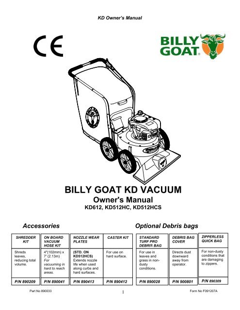
BILLY GOAT KD VACUUM
KD612 - Billy Goat
KD612 - Billy Goat
- No tags were found...

You also want an ePaper? Increase the reach of your titles
YUMPU automatically turns print PDFs into web optimized ePapers that Google loves.
<strong>KD</strong> Owner’s Manual<br />
<strong>BILLY</strong> <strong>GOAT</strong> <strong>KD</strong> <strong>VACUUM</strong><br />
Owner's Manual<br />
<strong>KD</strong>612, <strong>KD</strong>512HC, <strong>KD</strong>512HCS<br />
Accessories<br />
Optional Debris bags<br />
SHREDDER<br />
KIT<br />
ON BOARD<br />
<strong>VACUUM</strong><br />
HOSE KIT<br />
NOZZLE WEAR<br />
PLATES<br />
CASTER KIT<br />
STANDARD<br />
TURF PRO<br />
DEBRIS BAG<br />
DEBRIS BAG<br />
COVER<br />
ZIPPERLESS<br />
QUICK BAG<br />
Shreds<br />
leaves,<br />
reducing total<br />
volume.<br />
4"(102mm) x<br />
7' (2.13m)<br />
For<br />
vacuuming in<br />
hard to reach<br />
areas.<br />
(STD. ON<br />
<strong>KD</strong>512HCS)<br />
Extends nozzle<br />
life when used<br />
along curbs and<br />
hard surfaces.<br />
For use on<br />
hard surface.<br />
For use in<br />
leaves and<br />
grass in nondusty<br />
conditions.<br />
Directs dust<br />
downward<br />
away from<br />
operator.<br />
For non-dusty<br />
conditions that<br />
are damaging<br />
to zippers.<br />
P/N 890209<br />
P/N 890041<br />
P/N 890413<br />
P/N 890412<br />
P/N 890028<br />
P/N 900801<br />
P/N 890309<br />
Part No 890033<br />
1<br />
Form No F091207A
<strong>KD</strong> Owner’s Manual<br />
ABOUT THIS MANUAL<br />
THANK YOU for purchasing a <strong>BILLY</strong> <strong>GOAT</strong> ® <strong>KD</strong> Vacuum. Your new machine has been carefully designed and<br />
manufactured to provide years of reliable and productive service. This manual provides complete operating and<br />
maintenance instructions that will help to maintain your machine in top running order. Read this manual carefully<br />
before assembling, operating, or servicing your equipment.<br />
CONTENTS<br />
SERIAL PLATE DATA AND SPECIFICATIONS 3<br />
GENERAL SAFETY 4 -5<br />
SOUND AND VIBRATION 6<br />
INSTRUCTION LABELS 7<br />
PACKING CHECKLIST & ASSEMBLY 8<br />
OPERATION 9-10<br />
MAINTENANCE 11<br />
TROUBLESHOOTING AND WARRANTY PROCEDURE 12<br />
MAINTENANCE RECORD 13<br />
ILLUSTRATED PARTS & PARTS LISTS 14-15<br />
Part No 890033<br />
2<br />
Form No F091207A
<strong>KD</strong> Owner’s Manual<br />
SERIAL PLATE DATA<br />
Record the model number, serial number, date of<br />
purchase, and where purchased.<br />
Purchase Date:<br />
Purchased From:<br />
Specifications<br />
<strong>KD</strong>612 <strong>KD</strong>512HC <strong>KD</strong>512HCS<br />
Engine: HP 6.0 (4.47 kW) 5.5 (4.11 kW) 5.5 (4.11 kW)<br />
Engine: Type B & S QUANTUM HONDA OHC HONDA OHC<br />
Engine: Model 112K020124E1 GCV160AN1A GCV160AN1A<br />
Engine: Fuel Capacity 1.5 qt. (1.4 L) 1.16 qt. (1.1 L) 1.16 qt. (1.1 L)<br />
Engine: Oil Capacity 0.63 qt. (0.6 L) 0.58 qt. (0.6 L) 0.58 qt. (0.6 L)<br />
Total Unit Weight: 98# (44.5 kg) 99# (45.0 kg) 99# (45.0 kg)<br />
Overall Length 62” (1.57m) 62” (1.57m) 62” (1.57m)<br />
Overall Width 26.75” (0.68 m) 26.75” (0.68 m) 26.75” (0.68 m)<br />
Overall Height 42” (1.07m) 42” (1.07m) 42” (1.07m)<br />
Max. operating slope 20 0 20 0 20 0<br />
Sound in accordance with<br />
2000/14/EEC standards<br />
111 dBa 111 dBa 111 dBa<br />
Sound at operator’s ear 97 dBa 97dBa 97dBa<br />
Vibration at operator position 0.34 g (3.29m/s 2 ) 0.27 g (2.86m/s 2 ) 0.27 g (2.86m/s 2 )<br />
Part No 890033<br />
3<br />
Form No F091207A
<strong>KD</strong> Owner’s Manual<br />
GENERAL SAFETY INSTRUCTIONS and SYMBOLS<br />
The safety symbols shown below are used throughout this manual. You should become familiar with them before<br />
assembling, operating, or servicing this equipment.<br />
This symbol indicates important information that will prevent injury to yourself or others.<br />
This symbol indicates ear protection is recommended when operating this equipment.<br />
This symbol indicates eye protection is recommended when operating this equipment.<br />
This symbol indicates gloves should be worn when servicing this equipment.<br />
This symbol indicates that this manual and the engine manufacturer’s manual should be read<br />
carefully before assembling, operation, or servicing this equipment.<br />
This symbol indicates important information that will prevent damage to your <strong>BILLY</strong> <strong>GOAT</strong> ®<br />
<strong>KD</strong> Vacuum.<br />
This symbol indicates the engine oil level should be checked before operating this<br />
equipment.<br />
Read and make sure you thoroughly understand the following safety precautions before assembling, operating or<br />
servicing this equipment:<br />
READ this manual and the engine manufacturer’s manual carefully before assembling,<br />
operating, or servicing this equipment.<br />
EAR PROTECTION is recommended when operating this equipment.<br />
EYE PROTECTION is recommended when operating this equipment.<br />
BREATHING PROTECTION is recommended when operating this equipment.<br />
EXHAUST from this product contains chemicals known to the State of California to cause<br />
cancer, birth defects or other reproductive harm.<br />
DO NOT operate this equipment on any unimproved forested, brushy, or grass covered land<br />
unless a spark arrester is installed on the muffler as required by Section 4442 of the<br />
California Public Resources Code. The arrester must be maintained in good working order.<br />
Other states may have similar laws. Federal laws apply on federal lands.<br />
DO NOT run engine in an enclosed area. Exhaust gases contain carbon monoxide, an<br />
odorless and possibly fatal poison.<br />
Part No 890033<br />
4<br />
Form No F091207A
<strong>KD</strong> Owner’s Manual<br />
DO NOT run this equipment indoors or in any poorly ventilated area. Refueling outdoors is<br />
recommended.<br />
DO NOT refuel this equipment while the engine is running. Allow engine to cool for at least<br />
two minutes before refueling.<br />
DO NOT store gasoline near an open flame.<br />
DO NOT remove gas cap while engine is running.<br />
DO NOT start or operate engine if strong odor of gasoline is present.<br />
DO NOT start or operate engine if gasoline is spilled. Move equipment away from spill until<br />
gasoline has completely evaporated.<br />
DO NOT smoke while filling the fuel tank.<br />
DO NOT check for spark with spark plug or spark plug wire removed. Use an approved spark<br />
tester.<br />
DO NOT operate engine without a muffler. Inspect muffler periodically and replace if<br />
necessary. If equipped with muffler deflector, inspect deflector periodically and replace if<br />
necessary.<br />
DO NOT operate engine with grass, leaves or other combustible material near the muffler.<br />
DO NOT touch muffler, cylinder, or cooling fins when hot. Contact with hot surfaces may<br />
cause severe burns.<br />
DO NOT leave equipment unattended while in operation.<br />
DO NOT park equipment on a steep grade or slope.<br />
DO NOT operate equipment with bystanders in or near the work area.<br />
DO NOT allow children to operate this equipment.<br />
DO NOT operate equipment with guards removed.<br />
DO NOT operate equipment near hot or burning debris or any toxic or explosive materials.<br />
DO NOT operate equipment on slopes greater than specified in Specifications section of this<br />
manual.<br />
DO NOT place hands or feet underneath unit, or near any moving parts.<br />
ALWAYS remove spark plug wire when servicing equipment to prevent accidental starting.<br />
ALWAYS check fuel lines and fittings frequently for cracks or leaks. Replace if necessary.<br />
ALWAYS keep hands and feet away from moving or rotating parts.<br />
ALWAYS store fuel in approved safety containers.<br />
WARNING: Important<br />
Remove all rocks, wire, string, plastic, etc. that can present a hazard during work prior to<br />
starting.<br />
DO identify and mark all fixed objects to be avoided during work such as sprinkler heads,<br />
water valves, buried cables, or clothes line anchors, etc.<br />
Part No 890033<br />
5<br />
Form No F091207A
<strong>KD</strong> Owner’s Manual<br />
SOUND<br />
SOUND LEVEL 97 dB(a) at Operator Position<br />
Sound tests were conducted in accordance with 2000/14/EEC, and were performed on 2-21-2002 under the<br />
conditions listed below.<br />
Sound power level listed is the highest value for any model covered in this manual. Please refer to serial plate on<br />
the unit for the sound power level for your model.<br />
General Conditions:<br />
Sunny<br />
Temperature: 45 o F (7.2 o C)<br />
Wind Speed:<br />
5 mph (8.1 kmh)<br />
Wind Direction:<br />
South West<br />
Humidity: 60%<br />
Barometric Pressure:<br />
30.18”Hg (767 mm Hg)<br />
VIBRATION DATA<br />
VIBRATION LEVEL 0.34g (3.29m/s 2 )<br />
Vibration levels at the operator’s handles were measured in the vertical, lateral and longitudinal directions using<br />
calibrated vibration test equipment. Tests were performed on 5-25-2006 under the conditions listed below.<br />
General Conditions:<br />
Sunny<br />
Temperature: 89 o F (31.7 o C)<br />
Wind Speed:<br />
13.6 mph (21.9kph)<br />
Wind Direction:<br />
East<br />
Humidity: 22.8%<br />
Barometric Pressure:<br />
29.9Hg (101.3kpa)<br />
INTENDED USE<br />
INTENDED USE: This machine is designed for vacuuming leaves, grass clippings and other types of organic litter<br />
and for chipping brush, limbs, corn and sunflower stalks and palm fronds.<br />
Debris mixed with cans, bottles and small amounts of sand can be vacuumed; however, it is not this machine's<br />
primary purpose. Vacuuming cans, bottles and sand will affect the longevity of your machine.<br />
Do not operate if excessive vibration occurs. If excessive vibration occurs, shut engine off immediately and check<br />
for damaged or worn impeller, loose impeller bolt, loose impeller key, loose engine or lodged foreign objects.<br />
Note: See parts list for proper impeller bolt torque specifications. (See trouble shooting section on page 12).<br />
Part No 890033<br />
6<br />
Form No F091207A
<strong>KD</strong> Owner’s Manual<br />
INSTRUCTION LABELS<br />
The labels shown below were installed on your <strong>BILLY</strong> <strong>GOAT</strong> ® <strong>KD</strong> Vacuum. If any labels are damaged or missing, replace them before operating<br />
this equipment. Item numbers from the Illustrated Parts List and part numbers are provided for convenience in ordering replacement labels. The<br />
correct position for each label may be determined by referring to the Figure and Item numbers shown.<br />
LABEL DANGER KEEP HANDS LABEL EAR EYE BREATHING ITEM #49 DANGER FLYING DEBRIS<br />
AND FEET AWAY P/N 890254 ITEM # 62 P/N 810736<br />
ITEM #29 P/N 400424<br />
LABEL READ MANUAL LABEL EXPLOSIVE FUEL DEBRIS BAG LABEL<br />
ITEM #84 P/N 430363 ITEM # 63 P/N 400268 ITEM #1<br />
ENGINE LABELS<br />
HONDA<br />
BRIGGS & STRATTON<br />
Read Owner’s Manual Before Operating.<br />
Lire le manuel d’utilisation avant la mise en route.<br />
Vor Inbetriebnahme Bedienungs - und Wartungsanleitung lesen.<br />
Favor leer las instrucciones de operacion antes de operar el motor.<br />
Consultare il Manuale Uso e Manutenzione prima dell utilizzo.<br />
Las Skotselinstruktionen Innan Start.<br />
ENGINE CONTROLS<br />
Honda<br />
Choke<br />
Control<br />
Throttle Control<br />
Choke Control<br />
Throttle<br />
Control<br />
Fuel Shut Off<br />
Briggs engines have a primer<br />
button carburetor rather than<br />
choke type carburetor.<br />
Part No 890033<br />
7<br />
Form No F091207A
<strong>KD</strong> Owner’s Manual<br />
PACKING CHECKLIST<br />
Your Billy Goat <strong>KD</strong> Vacuum is shipped from the factory in one carton, completely assembled except for the<br />
upper handle, debris bag, and bag quick disconnect.<br />
READ all safety instructions before assembling unit.<br />
TAKE CAUTION when removing the unit from the box the Handle Assembly is attached by<br />
cables and folded over<br />
PUT OIL IN ENGINE BEFORE STARTING<br />
PARTS BAG &<br />
LITERATURE ASSY<br />
Warranty card P/N- 400972, Owner’s Manual P/N-890033, Declaration of Conformity P/N-890393.<br />
Quick disconnect<br />
Boxing Parts<br />
Checklist<br />
Debris Bag<br />
P/N-890022<br />
Literature Assy<br />
P/N-890392<br />
Connector Quick<br />
Disconnect<br />
P/N-890176<br />
Honda 5.5GVC<br />
160<br />
Briggs & Stratton<br />
6.0 HP Intek<br />
Fig. 2<br />
ASSEMBLY<br />
1. ASSEMBLE Lift upper handle (item 6), remove items 8, 30, & 32 from lower handle (item 27). Attach and secure<br />
upper handle as shown using same hardware.<br />
2. UNFOLD the debris bag (item 1) and fasten bag neck to bag quick disconnect (item 64). Attach firmly to housing<br />
exhaust (item 52) see fig. 2.<br />
3. ATTACH bag hanger strap to bag supports (item 11), preassembled to upper handle.<br />
4. CONNECT spark plug wire.<br />
Part No 890033<br />
8<br />
Form No F091207A
<strong>KD</strong> Owner’s Manual<br />
OPERATION<br />
Like all mechanical tools, reasonable care must be used when operating machine.<br />
Inspect machine work area and machine before operating. Make sure that all operators of this<br />
equipment are trained in general machine use and safety.<br />
PUT OIL IN ENGINE BEFORE STARTING<br />
STARTING<br />
ENGINE: See engine manufacturer’s instructions for type and amount of oil and gasoline used. Engine<br />
must be level when checking and filling oil and gasoline.<br />
ENGINE SPEED: Controlled by throttle lever on the engine. Under normal conditions, operate at minimum<br />
throttle to accomplish your current cleaning task.<br />
FUEL VALVE: Move fuel valve to "ON" position (when provided on engine).<br />
CHOKE: Located on engine and must be controlled manually.<br />
PRIMER: Push primer per engine instructions (B&S only).<br />
THROTTLE: Located on engine and must be controlled manually.<br />
IF YOUR UNIT FAILS TO START:<br />
See Troubleshooting on page 12.<br />
HANDLING & TRANSPORTING:<br />
This unit requires two people to lift it. With the handle in the folded position, lift holding the<br />
lower handle and belt/shaft guard one on each side of the machine. Secure the machine in place<br />
during transport. See page 3 for weight specifications<br />
Never lift the machine while the engine is running.<br />
STORAGE<br />
Never store engine indoors or in enclosed poorly ventilated areas with fuel in tank, where fuel fumes may reach<br />
an open flame, spark or pilot light, as on a furnace, water heater, clothes dryer or other gas appliance.<br />
If engine is to be unused for 30 days or more, prepare as follows:<br />
Remove all gasoline from carburetor and fuel tank to prevent gum deposits from forming on these parts and<br />
causing possible malfunction of engine. Drain fuel outdoors, into an approved container, away from open flame. Be<br />
sure engine is cool. Do not smoke. Run engine until fuel tank is empty and engine runs out of gasoline.<br />
Part No 890033<br />
9<br />
Form No F091207A
<strong>KD</strong> Owner’s Manual<br />
OPERATION<br />
<strong>VACUUM</strong>ING OPERATION<br />
<strong>VACUUM</strong> NOZZLE HEIGHT ADJUSTMENT: is raised and lowered by pulling slightly upward on handle and<br />
pulling height adjust knob on the handle (item 23) up at left rear of machine.<br />
FOR MAXIMUM PICKUP: Adjust nozzle close to debris, but without blocking airflow into the nozzle. NOTE:<br />
Never bury nozzle into debris.<br />
CLEARING A CLOGGED NOZZLE & EXHAUST: Turn engine off and wait for impeller to stop completely<br />
and disconnect spark plug wire. Wearing durable gloves, remove clog. Danger, the clog may contain sharp<br />
materials. Reconnect spark plug wire.<br />
DEBRIS BAG<br />
Debris bags are normal replaceable wear items.<br />
Note: Frequently empty debris to prevent bag overloading with more weight than you can lift.<br />
An optional bag and dust cover is available for use where debris will be vacuumed in dusty conditions (see Optional<br />
Accessories shown on page 1).<br />
DO NOT place bag on or near hot surface, such as engine. Run engine at 1/2 throttle for first 1/2 hour to condition new bag. Your<br />
new bag requires a break-in period to condition the pores of the material against premature blockage. The entire bag surface<br />
serves as a filter, and must be able to breath to have good vacuum performance. Be sure engine has come to a complete stop<br />
before removing or emptying bag.<br />
This vacuum is designed for picking up trash, organic material and other similar debris (see Safety Warnings<br />
page 4-5).<br />
However, many vacuums are used where dust is mixed with trash. Your unit can intermittently vacuum in dusty areas.<br />
Dust is the greatest cause of lost vacuum performance. However, following these rules will help maintain your<br />
machine's ability to vacuum in dusty conditions:<br />
• Run machine at idle to quarter throttle.<br />
• The debris bag must be cleaned more frequently. A vacuum with a clean, pillow soft bag will have good pickup<br />
performance. One with a dirty, tight bag will have poor pickup performance. If dirty, empty debris and vigorously shake<br />
bag free of dust.<br />
• Pressure-wash debris bag if normal cleaning does not fully clean bag. Bag should be thoroughly dry before use.<br />
NOTE: Having one or more spare debris bags is a good way to reduce down time while dirty bags are being cleaned.<br />
DO NOT leave debris in bag while in storage.<br />
COMPOST<br />
Vacuumed leaves, grass and other organic material from your own yard can be emptied into a pile or composter to<br />
provide enriched soil for later use as fertilizer in gardens and flower beds<br />
NOTE: Allow green chips to dry before spreading around living plants.<br />
Part No 890033<br />
10<br />
Form No F091207A
<strong>KD</strong> Owner’s Manual<br />
MAINTENANCE<br />
PERIODIC MAINTENANCE<br />
Periodic maintenance should be performed at the following intervals:<br />
Maintenance Operation Every Use (daily) Every 5 hrs (daily) Every 25 Hours<br />
Inspect for loose, worn or damaged parts.<br />
Clean Debris bag<br />
Check bag strap tightness<br />
Engine (See Engine Manual)<br />
Check for excessive vibration<br />
Lubricate wheels<br />
•<br />
•<br />
•<br />
•<br />
•<br />
IMPELLER REMOVAL<br />
1.Wait for engine to cool and disconnect spark plug.<br />
2.Drain fuel and oil from the engine.<br />
3. Remove bag, quick release, and upper handle. Do not kink, stretch, or break control cables, control<br />
housings, or end fittings while removing handles.<br />
4. Remove housing top plate by removing bolts around outside of housing.<br />
5. Leaving engine fastened to top plate, turn it upside down so the impeller is on top.<br />
6. Remove impeller bolt and lock washer.<br />
7. Lift impeller upward. If impeller slides freely, proceed to (step 10).<br />
8. Place two crowbars between impeller and housing on opposite sides. Pry impeller away from engine until it<br />
loosens. Using a penetrating oil can help loosen a stuck impeller.<br />
9. If the impeller does not loosen, obtain a 1” (25.4mm) longer bolt of the same diameter and thread type as<br />
the impeller bolt. Thread longer bolt by hand into the crankshaft until bolt bottoms. Using a suitable gear or<br />
wheel puller against the bolt head and the impeller back-plate (near the blades), remove impeller from shaft.<br />
10. Using a new impeller bolt and lockwasher, reinstall new impeller in reverse order.<br />
11. Tighten impeller bolt. Torque impeller bolt to 50 Ft. Lbs. (68 N.m) (see item 51 on page 15).<br />
12. Reinstall engine onto housing in reverse order of removal.<br />
13. Gas and oil (0.69 quart).<br />
14. Reinstall spark plug wire.<br />
Part No 890033<br />
11<br />
Form No F091207A
<strong>KD</strong> Owner’s Manual<br />
Troubleshooting<br />
Problem Possible Cause Solution<br />
Abnormal vibration.<br />
· Loose or out of balance impeller or<br />
loose engine<br />
· Check impeller and replace if required.<br />
Check engine<br />
W ill not vacuum or has poor<br />
vacuum performance<br />
Engine will not start.<br />
· dirty debris bag. Nozzle height set too<br />
high or low. Hose kit cap missing.<br />
Clogged nozzle or exhaust. Excessive<br />
quantity of debris.<br />
· Stop switch off. Throttle in off position.<br />
Engine not in full choke position. Out of<br />
gasoline. Bad or old gasoline. Sparkplug<br />
wire disconnected. Dirty air cleaner<br />
· Clean debris bag. Shake bag clean or<br />
wash. Adjust nozzle height. Check for<br />
hose kit cap. Unclog nozzle or exhaust.<br />
Allow air to feed with debris<br />
· Check stop switches, throttle, choke<br />
position and gasoline. Connect spark<br />
plug wire. Clean or replace air filter. Or<br />
contact a qualified service person.<br />
Engine is locked, will not pull<br />
over.<br />
Nozzle scrapes ground in<br />
lowest height setting.<br />
· Debris locked in impeller. Engine<br />
problem.<br />
Nozzle height out of adjustment<br />
· See page 5. Contact a engine service<br />
dealer for engine problems<br />
Adjust nozzle height (See Nozzle height<br />
fine adjustment for hard surfaces on<br />
page 5<br />
When servicing engine refer to specific manufacturers engine owner's manual. Engine warranty is covered by the<br />
specific engine manufacturer. If your engine requires warranty or other repair work contact your local servicing<br />
engine dealer. When contacting a dealer for service it is a good idea to have your engine model number available<br />
for reference (See table page 3). If you cannot locate a servicing dealer in your area you can contact the<br />
manufacturers national service organization.<br />
To reach:<br />
American Honda: 800-426-7701<br />
WARRANTY CLAIM PROCEDURE<br />
Should a <strong>BILLY</strong> <strong>GOAT</strong> ® machine fail due to a defect in material and/or workmanship, the owner should make a<br />
warranty claim as follows:<br />
• The machine must be taken to the dealer from whom it was purchased or to an authorized Servicing <strong>BILLY</strong><br />
<strong>GOAT</strong> Dealer.<br />
• The owner must present the remaining half of the Warranty Registration Card, or, if this is not available, the<br />
invoice or receipt.<br />
• The Warranty Claim will be completed by the authorized <strong>BILLY</strong> <strong>GOAT</strong> Dealer and submitted to their<br />
respective <strong>BILLY</strong> <strong>GOAT</strong> Distributor for their territory Attention: Service Manager. Any parts replaced under<br />
warranty must be tagged and retained for 90 days. The model number and serial number of the unit must<br />
be stated in the Warranty Claim.<br />
• The distributor service manager will sign off on the claim and submit it to <strong>BILLY</strong> <strong>GOAT</strong> for consideration.<br />
• The Technical Service Department at <strong>BILLY</strong> <strong>GOAT</strong> will study the claim and may request parts to be<br />
returned for examination. <strong>BILLY</strong> <strong>GOAT</strong> will notify their conclusions to the distributor service manager from<br />
whom the claim was received.<br />
• The decision by the Technical Service Department at <strong>BILLY</strong> <strong>GOAT</strong> to approve or reject a Warranty Claim is<br />
final and binding.<br />
For online product registration go to www.billygoat.com<br />
Part No 890033<br />
12<br />
Form No F091207A
<strong>KD</strong> Owner’s Manual<br />
MAINTENANCE RECORD<br />
Date<br />
Service Performed<br />
Part No 890033<br />
13<br />
Form No F091207A
<strong>KD</strong> Owner’s Manual<br />
PARTS DRAWING <strong>KD</strong><br />
Part No 890033<br />
14<br />
Form No F091207A
<strong>KD</strong> Owner’s Manual<br />
* Denotes<br />
standard<br />
hardware<br />
item that<br />
may be<br />
purchase<br />
d locally.<br />
PARTS LIST<br />
Part No 890033<br />
ITEM <strong>KD</strong>612 <strong>KD</strong>512HC <strong>KD</strong>512HCS<br />
DESCRIPTION QTY QTY<br />
NO. Part No. Part No. Part No.<br />
QTY<br />
1 PRO DEBRIS BAG (service) 890305 1 890023 1 890023 1<br />
2<br />
3<br />
4 NUT LOCK (1/4 - 20 ) *8160001 7 *8160001 7 *8160001 7<br />
5 SCREW CAP ( 1/4 - 20 x 1-1/2 HEX ) *8041008 8 *8041008 8 *8041008 8<br />
6 HANDLE ASS’Y (incl. items 4(5),5(5),11(2),75(2),76) 900054 1 900054 1 900054 1<br />
7 AXLE HEIGHT ADJUST 890389 1 890389 1 890389 1<br />
8 SCREW HANDLE 5/16 - 18 x 1 - 3/4 *8041031 2 *8041031 2 *8041031 2<br />
9 CLAMP CABLE 900407 2 900407 2 900407 2<br />
10 SCREW CAP 1/4 - 20 x 1 3/4 *8041009 1 *8041009 1 *8041009 1<br />
11 BAR BAG SUPPORT 900039 2 900039 2 900039 2<br />
12 DOOR EXHAUST ASS’Y (incl. item 62 ) 890148 1 890148 1 890148 1<br />
13 PLATE TOP ASS’Y (incl. items 29, 57, 65) 890402 1 890402 1 890402 1<br />
14 SCREWCAP 1/4-20 X3/4 HCS ZP 8041004 2 8041004 2 8041004 2<br />
15 WASHER FLAT 5/16 8172008 1 8172008 1 8172008 1<br />
16 WASHER 1/4 FC ZP *8171002 10 *8171002 10 *8171002 10<br />
17<br />
18 BRACKET - HEIGHT ADJUSTMENT 890021 1 890021 1 890021 1<br />
19 PLATE UPPER HEIGHT ADJUST 890005 1 890005 1 890005 1<br />
20 SPRING 900136 1 900136 1 900136 1<br />
21 TIRE - ONLY (PER ASSY) 900507 1 900507 1 900507 1<br />
22 PIN - HAIR COTTER 900471 1 900471 1 900471 1<br />
23 CABLE HEIGHT ADJUSTMENT 890019 1 890019 1 890019 1<br />
24 BOLT - CARRIAGE 5/16 - 18 x 4 1/2 *8024054 4 *8024054 4 *8024054 4<br />
25<br />
26 NUT LOCK 5/16 - 18 HEX *8160002 6 *8160002 6 *8160002 6<br />
27 HANDLE LOWER <strong>KD</strong>510 890346 1 890346 1 890346 1<br />
28 PLATE HANDLE SUPPORT 900933 1 -2 900933 1 -2 900933 1 -2<br />
29 LABEL DANGER CUT FINGER 400424 2 400424 2 400424 2<br />
30 WASHER FLAT CUT 5/16 *8171003 2 *8171003 2 *8171003 6<br />
31<br />
32 NUT LOCK 5/16 - 18 THIN HT. *8161041 4<br />
33 GRIP HANDLE 400570 2 400570 2<br />
34 WHEEL ASS’Y (incl. items 21) 900509 4 900509 4 900509 4<br />
35 WASHER 0.75 “C” 900997 0 -1 900997 0 -1 900997 0 -1<br />
36<br />
37 SCREW SM 1/4x3/4 TYPE A - - - - *8122082 4<br />
38 PLATE SKID (incl. items 54) - - - - 890413 1<br />
39 SPACER IMPELLER - - 890616 1 890616 1<br />
40<br />
41<br />
42 SCREW SELF TAPPING 10 - 24 x 1/2 *8123086 1 *8123086 1 *8123086 1<br />
43 NOZZLE MAINFRAME ASS’Y (incl. one of items 29,44,42) 890391 1 890391 1 890391 1<br />
44 PLUG 900146 1 900146 1 900146 1<br />
45 LINER HOLD PLATE 890618 2 890618 2 890618 2<br />
46 - - - -<br />
47 IMPELLER ASS’Y (incl. items 49, 50, 51 ) 900215 1 890615 1 890615 1<br />
48<br />
49 KEY 900162 2 900162 2 900162 2<br />
50 WASHER LOCK 3/8 TWISTED TOOTH 400502 1 400502 1 400502 1<br />
51 SCREW CAP 3/8 -24 x 1 GR 8 (TORQ.50 FT-LBS)(68N.m) 900154 1 900154 1 900154 1<br />
52 HOUSING ASS’Y (incl. items 12, 14, 15, 16, 66) 890371-S 1 890371-S 1 890417-S 1<br />
53 ENGINE HONDA 5.5 H.P. GC160 - - 890614 1 890614 1<br />
ENGINE BRIGGS & STRATTON 6 H.P. QUANTUM IC 890622 1 - - - -<br />
54 BOLT CARRIAGE 5/16-18x3/4" - - - - 8024039 4<br />
55 LINE PVC - - - - 900732-S 1<br />
56 SCREW CAP 3/8 - 1-1/2 TAPTITE 890408 3 890408 4 890408 4<br />
57 SCREW CAP 1/4 - 20 x 1/2 HWH 890359 15 890359 15 890359 15<br />
58 WASHER FLAT 1/2 SAE *8172011 8 *8172011 8 *8172011 8<br />
59 SCREW SOCKET HD. 5/16 - 18 x 3/4 GR. 8<br />
60 HGT ADJUST ASSY (INCL. ITEMS 18, 20, 22, 23) 890013 1 890013 1 890013 1<br />
61 1/2-13 CAP NUT NP W/PATCH 890530 4 890530 4 890530 4<br />
62 LABEL DANGER FLYING MATERIAL 810736 1 810736 1 810736 1<br />
63 LABEL DO NOT FILL WHEN ENGINE IS HOT 400268 1 400268 1 400268 1<br />
64 CONNECTOR BAG QUICK 890176 1 890176 1 890176 1<br />
65 LABEL READ OWNER'S MANUAL 890301 1 890301 1 890301 1<br />
66 LABEL EAR/EYE BREATHING 890254 1 890254 1 890254 1<br />
15<br />
Form No F091207A
<strong>KD</strong> Owner’s Manual<br />
BRUSH CUTTER FORCE BLOWER AERATOR<br />
If you liked this product please feel<br />
free to view our full line of quality lawn<br />
care, renovation, and debris removal<br />
products at www.billygoat.com<br />
DL <strong>VACUUM</strong> MULTI <strong>VACUUM</strong> POWER RAKE<br />
Part No 890033<br />
16<br />
Form No F091207A