e2i / LONWORKS - ELKA-Elektronik GmbH
e2i / LONWORKS - ELKA-Elektronik GmbH
e2i / LONWORKS - ELKA-Elektronik GmbH

Create successful ePaper yourself
Turn your PDF publications into a flip-book with our unique Google optimized e-Paper software.
GB<br />
Mounting and Operating Instructions<br />
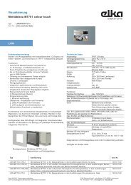
Room control panel SmartSensor incl. UP-Controller LON type RC10 ULF, 1-fold, RCP 7331 ULF xx<br />
Room control panel SmartSensor incl. UP-Controller LON type RC10 ULF, 2-fold, RCP 7332 ULF xx<br />
Room control panel SmartSensor incl. UP-Controller LON type RC10 ULF, 3-fold, RCP 7333 ULF xx<br />
Room control panel SmartSensor incl. UP-Controller LON type RC10 ULF, 4-fold, RCP 7334 ULF xx<br />
Description<br />
The controller RC10 ULF flush-mountig connects a <strong>LONWORKS</strong> ® -network with an <strong>e2i</strong>-bus system. It acts as an <strong>e2i</strong>controller<br />
and supplies the connected <strong>e2i</strong>-modules with power. The room control panel SmartSensor is employed<br />
as <strong>e2i</strong>-module. It disposes of the following elements: LC-display, navigation knob (turn/push), operation keys,<br />
temperature sensor. The function of the combination SmartSensor / controller RC10 ULF is defined by<br />
parameterization.<br />
Functions<br />
Confer to operating instruction of room control panel<br />
Technical data<br />
Transceiver : FTT 10A<br />
External additional supply<br />
Power consumption additional supply<br />
: 24 V AC/DC (+/- 10 %), max. 75 W<br />
according to EN 61558-2-6 (VDE 0570 Teil 2-6)<br />
Room control panel incl. RC10 ULF : max. 2 W at 24V AC/DC<br />
per external bus load (illustration B, �) : max. 60 mW/at DC<br />
max. 84 mW/at AC<br />
Max. cable length <strong>e2i</strong>-bus : 50 m<br />
Max. number <strong>e2i</strong>-participants : depending on parameterization<br />
Max. number of bus loads : 44<br />
Cable type <strong>e2i</strong>-bus<br />
Connections<br />
: J-Y(St)Y 2x2x0,6 or J-Y(St)Y 2x2x0,8<br />
<strong>e2i</strong>-Bus (external) : 4-pole clamp (grey)<br />
<strong>e2i</strong>-Bus (internal) : 2x5-pole clamp<br />
24-V-supply : 2-pole clamp (yellow-white)<br />
<strong>LONWORKS</strong> ®<br />
: 2-pole clamp (red-black)<br />
Ambient temperature : -5 °C to+45 °C<br />
Storage-/Transport temperature : -25 °C to +70 °C<br />
Protection type : IP 20<br />
Protection class : III<br />
Installation depth<br />
Suitable junction switch box, e.g.<br />
: 32 mm<br />
flush-mounting : double junction switch box, Kaiser Art.-No. 1656-02<br />
hollow wall : double junction switch box, Kaiser Art.-No. 9062-02<br />
Kaiser Art.-No. 9062-77 (halogen free)<br />
concrete : B2 universal box<br />
Spelsberg Art.-No. 974 002 01, plus 4 pcs. mounting bridge<br />
Spelsberg Art.-No. 974 120 01, plus 4 pcs. srews<br />
Spelsberg Art.-No. 974 130 01<br />
System description<br />
The SmartSensor is a product of the <strong>e2i</strong>-bus system and can only be used in combination with the corresponding<br />
LON-controller.<br />
The LON-Controller RC10 ULF is a product in <strong>LONWORKS</strong> ® -technology.<br />
Detailed expertise is required for understanding.<br />
The function of the device depends on parameterization.<br />
Planning, installation and start-up of the device are effected by means of a PC-software.<br />
D<br />
Montage- und Bedienungsanleitung<br />
Raumbediengerät SmartSensor inkl. UP-Controller LON Typ RC10 ULF, 1-fach, RCP 7331 ULF xx<br />
Raumbediengerät SmartSensor inkl. UP-Controller LON Typ RC10 ULF, 2-fach, RCP 7332 ULF xx<br />
Raumbediengerät SmartSensor inkl. UP-Controller LON Typ RC10 ULF, 3-fach, RCP 7333 ULF xx<br />
Raumbediengerät SmartSensor inkl. UP-Controller LON Typ RC10 ULF, 4-fach, RCP 7334 ULF xx<br />
Beschreibung<br />
Der UP-Controller RC10 ULF stellt die Verbindung zwischen einem <strong>LONWORKS</strong> ® -Netzwerk und einem <strong>e2i</strong>-Bussystem<br />
her. Er dient als <strong>e2i</strong>-Controller und versorgt die angeschlossenen <strong>e2i</strong>-Module mit Spannung. Das Raumbediengerät<br />
SmartSensor ist als <strong>e2i</strong>-Modul ausgeführt. Es verfügt über folgende Elemente: LC-Display, Navigationsknopf<br />
(Drehen/Drücken), Bedientasten, Temperatursensor. Die Funktion der Kombination SmartSensor / UP-Controller<br />
RC10 ULF wird durch die Parametrierung definiert.<br />
Funktionen<br />
Siehe Bedienungsanleitung Raumbediengerät<br />
Technische Daten<br />
Transceiver : FTT 10A<br />
Externe Zusatzversorgung<br />
Leistungsaufnahme Zusatzversorgung<br />
: 24 V AC/DC (+/- 10%), max. 75 W<br />
gemäß DIN EN 61558-2-6 (VDE 0570 Teil 2-6)<br />
Raumbediengerät inkl. RC10 ULF : max. 2 W bei 24V AC/DC<br />
pro externe Buslast (Bild B, �) : max. 60 mW/bei DC<br />
max. 84 mW/bei AC<br />
Max. Leitungslänge <strong>e2i</strong>-Bus : 50 m<br />
Max. Anzahl <strong>e2i</strong>-Teilnehmer : je nach Parametrierung<br />
Max. Anzahl Buslasten : 44<br />
Leitungstyp <strong>e2i</strong>-Bus<br />
Anschlüsse<br />
: J-Y(St)Y 2x2x0,6 oder J-Y(St)Y 2x2x0,8<br />
<strong>e2i</strong>-Bus (extern) : 4-pol. Klemme (grau)<br />
<strong>e2i</strong>-Bus (intern) : 2x5-pol. Klemme<br />
24-V-Versorgung : 2-pol. Klemme (gelb-weiß)<br />
<strong>LONWORKS</strong> ®<br />
: 2-pol. Klemme (rot-schwarz)<br />
Umgebungstemperatur : -5 °C bis +45 °C<br />
Lager-/Transporttemperatur : -25 °C bis +70 °C<br />
Schutzart : IP 20<br />
Schutzklasse : III<br />
Einbautiefe<br />
Passende Installationsdosen, z.B.<br />
: 32 mm<br />
UP : Doppelgeräte-Verbindungsdose, Kaiser Art.-Nr. 1656-02<br />
Hohlwand : Doppelgeräte-Verbindungsdose, Kaiser Art.-Nr. 9062-02<br />
Kaiser Art.-Nr. 9062-77 (halogenfrei)<br />
Beton : B2 Universalkasten<br />
Spelsberg Art.-Nr. 974 002 01, plus 4 Stück Montagebrücken<br />
Spelsberg Art.-Nr. 974 120 01, plus 4 Stück Schrauben<br />
Spelsberg Art.-Nr. 974 130 01<br />
Systembeschreibung<br />
Der SmartSensor ist ein Produkt des <strong>e2i</strong>-Bussystems und kann nur in Verbindung mit einem passenden LON-<br />
Controller verwendet werden.<br />
Der LON-Controller RC10 ULF ist ein Produkt in <strong>LONWORKS</strong> ® Technologie. Über diesen Controller erfolgt die<br />
Einbindung in <strong>LONWORKS</strong> ® -Netzwerke.<br />
Detaillierte Fachkenntnisse werden zum Verständnis vorausgesetzt.<br />
Die Funktion des Gerätes ist abhängig von der Parametrierung.<br />
Planung, Installation und Inbetriebnahme des Gerätes erfolgen mit Hilfe einer PC-Software.<br />
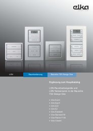
<strong>e2i</strong> / <strong>LONWORKS</strong> ®<br />
Raumbediengerät SmartSensor<br />
inkl. UP-Controller LON Typ<br />
RC10 ULF<br />
1-fach<br />
RCP 7331 ULF xx Art. Nr. 131 04 9x1<br />
2-fach<br />
RCP 7332 ULF xx Art. Nr. 131 04 9x2<br />
3-fach<br />
RCP 7333 ULF xx Art. Nr. 131 04 9x3<br />
4-fach<br />
RCP 7334 ULF xx Art. Nr. 131 04 9x4<br />
Montage- und Bedienungsanleitung<br />
<strong>ELKA</strong>-<strong>Elektronik</strong> <strong>GmbH</strong><br />
Talstraße 104<br />
D-58515 Lüdenscheid<br />
Tel.: 0 23 51 - 176-0<br />
Fax: 0 23 51 - 176-4900<br />
www.elka.de<br />
info@elka.de<br />
825 458 04 06.04
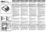
(A)<br />
(B)<br />
(C)<br />
(D)<br />
(E)<br />
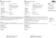
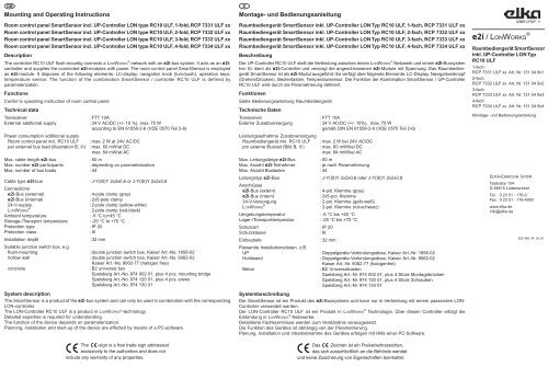
Geräte-Oberseite<br />
(<strong>e2i</strong>-Controller RC10 ULF)<br />
Geräte-Unterseite<br />
(<strong>e2i</strong>-Controller RC10 ULF)<br />
Gefahrenhinweise<br />
D Safety instructions<br />
GB<br />
Achtung! Einbau und Montage elektrischer Geräte dürfen nur durch eine Elektrofachkraft erfolgen. Attention: Electrical appliances must be installed and fitted only by qualified electricians and in<br />
Dabei sind die geltenden Unfallverhütungsvorschriften zu beachten.<br />
observance of the current accident prevention regulations.<br />
Bei Nichtbeachtung der Installationshinweise können Schäden am Gerät, Brand oder andere Gefahren<br />
entstehen.<br />
Non-observance of the fitting instructions may damage the device or cause fire and other hazards.<br />
Montage<br />
• Installieren Sie den <strong>e2i</strong>-Controller RC10 ULF in eine passende Installationsdose (siehe technische Daten)<br />
oder in das modulare Installationssystem. Einbaulage siehe Bild (A).<br />
Montagehinweise zum Installationssystem finden Sie in der dort beiliegenden Dokumentation.<br />
• Verwenden Sie für die 24V-Spannungsversorgung einen Sicherheitstrafo entsprechend DIN EN 61558-2-6 (VDE<br />
0570 Teil 2-6). Schließen Sie diese mit der beiliegenden gelb-weißen Klemme an (Bild B, �).<br />
• Verlegen Sie die Leitung für die externe Versorgung und die <strong>e2i</strong>-Busleitung entsprechend den Richtlinien für<br />
Schutzkleinspannung (SELV).<br />
• Der Anschluss an das <strong>LONWORKS</strong> ® -Netzwerk erfolgt über die rot-schwarze Busklemme (Bild B, �).<br />
Hinweis: Sie können für die Zusatzversorgung das zweite Adernpaar der Busleitung verwenden (Spannungsfall<br />
und SELV beachten).<br />
• Schließen Sie die Adern der <strong>e2i</strong>-Busleitung über die beiliegende 4polige Anschlussklemme entsprechend der<br />
folgenden Tabelle an (Bild B, �):<br />
Anschlussbelegung der 4-pol. <strong>e2i</strong>-Bus-Klemme<br />
1. 24V rot<br />
2. <strong>e2i</strong> Data gelb<br />
3. <strong>e2i</strong> Clock weiß<br />
4. GND schwarz<br />
Vergabe der physikalischen Adresse:<br />
• Kommissionieren Sie den Controller mit einem geeigneten LNS-Tool<br />
(ggf. unter Verwendung der Service-Taste und -LED �+�).<br />
Montage des Raumbediengerätes SmartSensor:<br />
• Nach Abschluss der Programmierung des <strong>e2i</strong>-Controller RC10 ULF wird das Raumbediengerät (Bild C, �)<br />
auf den UP-Controller gesteckt.<br />
Die Kontaktierung erfolgt durch die <strong>e2i</strong>-Schnittstelle (Bild C, �).<br />
Bitte beachten!<br />
Es handelt sich bei der Schnittstelle (Bild C, �) nicht um eine EIB-Anwendungsschnittstelle! Daher<br />
dürfen hier keine EIB-Anwendungsmodule aufgesteckt werden.<br />
Nichtbeachten kann zu Beschädigungen am Gerät und/oder Fehlfunktionen führen.<br />
• Demontageschutz durch Verschraubung; siehe Bild D.<br />
• Entfernen Sie die Abdeckung der Beschriftungsfelder vorsichtig mit einem Schraubendreher oder mit dem<br />
Fingernagel entsprechend Bild E.<br />
Die Funktionalität des Raumbediengerätes wird über das Geräte-PlugIn definiert und muss entsprechend in das<br />
Produkt hinein geladen werden.<br />
Beschriften Sie das Raumbediengerät entsprechend der Programmierung. Notieren Sie die Grunddaten der<br />
Programmierung in der Bedienungsanleitung (Kap. „Konfiguration“ und „Sperren von Funktionen“) und<br />
übergeben Sie die Bedienungsanleitung Ihrem Kunden.<br />
Gewährleistung<br />
Wir leisten Gewähr im Rahmen der gesetzlichen Bestimmungen.<br />
Bitte schicken Sie das Gerät portofrei mit einer Fehlerbeschreibung an unsere zentrale Kundendienststelle:<br />
<strong>ELKA</strong>-<strong>Elektronik</strong> <strong>GmbH</strong><br />
Service Center<br />
Talstraße 104<br />
D-58515 Lüdenscheid<br />
www.elka.de<br />
info@elka.de<br />
Mounting<br />
• Install the <strong>e2i</strong>-controller RC10 ULF into a suitable junction switch box (see technical data) or into the modular<br />
installation system. Fitting positon see illustration (A).<br />
Mounting instructions for the installation system can be taken from the documentation which is included there.<br />
• Employ a safety transforer for the 24 V-power supply according to EN 61558-2-6 (VDE 0570 Teil 2-6). Connect<br />
it with the included yellow-white clamps (illustration B, �).<br />
• Pass the cable for external supply and the <strong>e2i</strong>-bus cable according to the guidelines for safety extra low<br />
voltage (SELV).<br />
• The connection to the <strong>LONWORKS</strong> ® -network is effected via the red-black bus clamp (illustration B, �).<br />
HINT: You can use the second wire pair of the bus cable for the additional supply (observe power failure and<br />
SELV).<br />
• Connect the wires of the <strong>e2i</strong>-bus cables via the included 4-pole connection clamp according to the following<br />
table (illustration B, �).<br />
Connection of the 4-pole <strong>e2i</strong>-bus clamp<br />
1. 24V red<br />
2. <strong>e2i</strong> Data yellow<br />
3. <strong>e2i</strong> Clock white<br />
4. GND black<br />
Allocation of physical address:<br />
• Commission the controller with a suitable LNS-tool<br />
(e.g. by using the service key and -LED �+�).<br />
Mounting of the room operation panelSmartSensor:<br />
• After programming of the <strong>e2i</strong>-controller RC10 ULF, the room operation panel (illustration C, �) is put onto the<br />
controller flush-mounting.<br />
Contacting is effected via the <strong>e2i</strong>-interface (illustration C, �).<br />
Please observe!<br />
The interface (ilustration C, �) is not an EIB application interface! Thus, no EIB application modules<br />
can be put onto.<br />
Non-observance can cause defects of the device and/or malfunctions.<br />
• Demounting protection by srew, see illustration D<br />
• Remove the cover over the inscription fields carefully with a screwdriver or your fingernail as shown in Fig. E<br />
The functionality of the room operation panel is defined by means of the device´s PlugIn and must be loaded into<br />
the product.<br />
Label the room operation panel according to the programming. Note the basic data of the programming in the<br />
operation instructions (chapter "configuration" and "locking of functions") and hand out the operation instructions<br />
to your customer.<br />
Acceptance of guarantee<br />
Our products are under guarantee within the scope of the statutory provisions.<br />
Please return the unit postage paid to our central service department giving a brief description of the fault:<br />
<strong>ELKA</strong>-<strong>Elektronik</strong> <strong>GmbH</strong><br />
Service Center<br />
Talstraße 104<br />
D-58515 Lüdenscheid<br />
www.elka.de<br />
info@elka.de