Tele Vue-NP101
Tele Vue-NP101is Operating Guide - TeleVue Optics
Tele Vue-NP101is Operating Guide - TeleVue Optics
- No tags were found...

Create successful ePaper yourself
Turn your PDF publications into a flip-book with our unique Google optimized e-Paper software.
<strong>Tele</strong> <strong>Vue</strong>-<strong>NP101</strong><br />
®<br />
is<br />
Operating Guide<br />
540mm f/5.4 IMAGING SYSTEM<br />
4-ELEMENT APO REFRACTOR<br />
Thank you for purchasing the <strong>Tele</strong> <strong>Vue</strong>-<strong>NP101</strong>is. It has been our pleasure to craft this fine instrument for<br />
you. Thirty years ago Al Nagler took Petzval’s portrait lens concept using widely spaced doublets, and<br />
patented a fast telescope design version for the purpose of testing eyepieces. The 5” f/4 MPT (Multi-<br />
Purpose <strong>Tele</strong>scope) with its fast speed, wide and flat field, led to a series of continuous improvements,<br />
primarily in color correction. The “Halley Commemorative,” 4” f/5.5 started the parade where more<br />
advanced glasses including special dispersion, fluorite and fluorite substitute glasses brought steady<br />
improvements. The 4” f/5 Genesis employed fluorite in the rear doublet and the SDF version at f/5.4<br />
and subsequent <strong>Tele</strong> <strong>Vue</strong>-101 version brought us closer to perfection. Maintaining the f/5.4 speed while<br />
reducing tube length in a totally new design with new glasses allowed virtually ideal color correction and<br />
improved field flatness in this, the ideal form culminating the 30-year refinement toward perfection with<br />
the Nagler-Petzval 101. Al’s “spacewalk” dream from his 1960’s NASA simulator days is yours to live.<br />
<strong>Tele</strong> <strong>Vue</strong>’s “is” designation denotes instruments capable of accepting Imaging System photographic<br />
accessories. <strong>Tele</strong> <strong>Vue</strong> has designed this series of accessories in conjunction with each optical system<br />
so you are ensured of compatibility and maximum performance. While the <strong>NP101</strong>is maintains all the<br />
visual prowess of the standard <strong>NP101</strong>, the larger rear elements and larger focuser along with a host of<br />
proprietary Imaging System accessories, make it ideally suited for the CCD imager.<br />
WARNING: NEVER try to look at the sun or point the telescope toward or near the sun without professional<br />
solar observing equipment rigidly secured in front of the objective lens. When observing the sun with the<br />
proper filters, remove any finding devices such as Starbeam from the telescope. Instant and<br />
permanent eye damage may result from viewing the sun directly, even during a solar eclipse,<br />
or when viewing through thin clouds, or when the sun is near the horizon.<br />
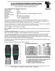
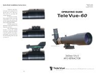
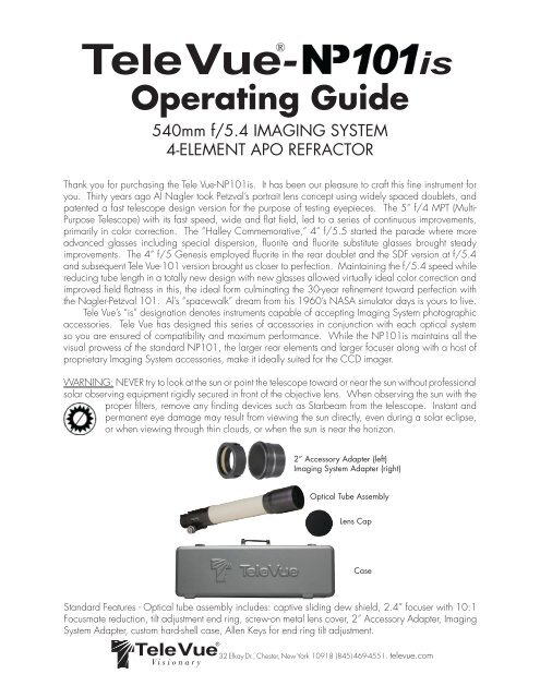
2” Accessory Adapter (left)<br />
Imaging System Adapter (right)<br />
Optical Tube Assembly<br />
Lens Cap<br />
Case<br />
Standard Features - Optical tube assembly includes: captive sliding dew shield, 2.4” focuser with 10:1<br />
Focusmate reduction, tilt adjustment end ring, screw-on metal lens cover, 2” Accessory Adapter, Imaging<br />
System Adapter, custom hard-shell case, Allen Keys for end ring tilt adjustment.<br />
<strong>Tele</strong> <strong>Vue</strong> ® 32 Elkay Dr., Chester, New York 10918 (845) 469-4551. televue.com<br />
Visionary
Getting Acquainted with the <strong>Tele</strong> <strong>Vue</strong>-<strong>NP101</strong>is<br />
1.1 Optical tube assembly<br />
The optical tube consists of an air-spaced doublet in the front cell, which attaches to the tube via three<br />
alignment screws. (Never touch the alignment screws in the front lens cell.) The rear doublet, making up the<br />
rest of the objective, is larger in diameter than the standard <strong>NP101</strong> and provides additional illumination<br />
at the edge of the field. This benefit is especially useful for large format CCD chips which are extremely<br />
sensitive to light fall-off. The rear lens group is housed in the cell that threads between the back of the tube<br />
and the focuser. Never stick any long objects into the focuser or you will hit the rear-most lens surface.<br />
1.2 Focuser<br />
The 2.4” output side of the <strong>NP101</strong>is focuser is designed to pass all of the field rays exiting the rear elements<br />
of the objective, as the forward end of the draw tube has a 3” internal diameter. A larger focuser,<br />
therefore, lends no additional illumination benefit.<br />
The telescope is shipped in its “visual” configuration. The 2” Accessory Adapter sits within the 2.4”<br />
inside diameter of the drawtube. Thumb screws pass through both the drawtube and adapter to cinch a<br />
brass clamp ring around 2” accessories. With three thumb screws there is enough holding power for the<br />
heaviest of visual accessories!<br />
The two tension screws on the top of the focuser body can be adjusted to add resistance when using<br />
heavy equipment. These tension screws tighten against a brass clamp ring, which then cinches down<br />
on the Teflon sleeve in which the draw tube slides. For photography it is not necessary to tighten beyond<br />
the need to keep a camera stationary but we do recommend to tighten them in unison to avoid any focus<br />
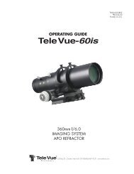
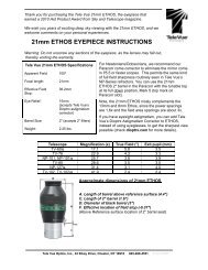
Jack Screws (typical) shift. Note that even when sufficiently tight,<br />
Digital Indicator Kit<br />
Mounting Points<br />
Drawtube Tension<br />
Screw (typical)<br />
Lock Screws<br />
(typical)<br />
Jam Screws<br />
(typical)<br />
2” Accessory<br />
Adapter<br />
the focuser knobs can still drive the draw tube.<br />
The end ring can be adjusted (and<br />
locked) to compensate for any tilt effects seen<br />
in CCD imaging. Lock screws in the end of<br />
the draw tube tighten against either the taper<br />
of the Imaging System Adapter or brass clamp<br />
ring within the 2” Accessory Adapter.<br />
The threaded holes on top of the focuser body<br />
accept the Digital Indicator Kit.<br />
Operation of the rack and pinion focuser is<br />
via the 10:1 ratio Focusmate on the right side<br />
or either of the 1:1 knobs. You might consider<br />
the optional Focusmate Driver for vibration-free<br />
focus control.<br />
1:1 Knob<br />
1:1 Knob<br />
10:1 Knob<br />
Focuser with 2” accessory adapter in place<br />
2
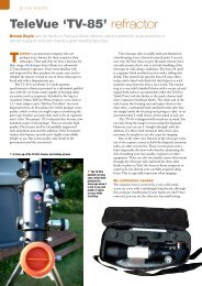
1.3 Case<br />
When opening the case, we recommend always lifting<br />
the lid while holding the handle. The lid opens a full 180°<br />
Optional Accessories Shown<br />
and holding the handle will give you a better grasp to insure that the lid doesn’t slip out of your hand. The<br />
interior of the case was designed to store your scope with the optional Starbeam, Focusmate Motor Driver<br />
and Digital Indicator Kit installed. To fit the Starbeam, you may have to slide your ring mount so that the<br />
Starbeam fits in the lid of the case between the accessory bags.<br />
The two accessory bags within the case lid are removable. IMPORTANT: Whenever carrying<br />
your telescope in the case, the accessory bags must be<br />
in place as they act to hold the telescope down. Failure<br />
to do so may result in the telescope rolling into the lid of<br />
the case and damage to the telescope may occur. These<br />
bags are held in place by Velcro and can be easily<br />
lifted out. Each bag will hold a variety of accessories,<br />
so remove the foam inserts as your needs require. The<br />
right side bag is where you’ll find the Imaging System<br />
Adapter. There is also an cutout for an optional Everbrite<br />
diagonal with 2” to 1¼” adapter inserted. Remember<br />
to zipper the bags closed before closing the case lid!<br />
Optional Accessories Shown<br />
2.0 Mounting Options and Set Up<br />
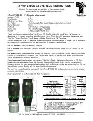
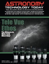
The telescope tube diameter is 4”. <strong>Tele</strong> <strong>Vue</strong> has two mount ring options available. The single ring (RS4-<br />
8004) and the dual ring (MRS-4011). The single ring is fine for visual and photographic use. It contains<br />
two machined grooves that accept the Starbeam (SFT-2003) unit power finder and the Piggy-Cam (PGC-<br />
1001) piggy back camera adapter. The RS4-8004 is<br />
recommended for use with all <strong>Tele</strong> <strong>Vue</strong> Alt-Az mounts<br />
as it allows greater balancing opportunities than the<br />
MRS-4011.<br />
The dual ring MRS-4011 is best suited for critical<br />
photography and CCD imaging. It also has grooves<br />
for mount accessories. A central bar spans across the<br />
top of the two rings and permits varying the spacings<br />
between the rings in order to fit a variety of mount<br />
heads. The BPL-1098 adapter plate on the bottom of<br />
MRS-4011 - Heavy duty tube ring set with<br />
slotted spreader bar to adjust ring spacing<br />
for a wide variety of equatorial mounts.<br />
the rings mounts directly to <strong>Tele</strong> <strong>Vue</strong> Alt-Az mounts and<br />
is drilled to mate to a variety of mounts or mounting<br />
adapter plates.<br />
3
For Alt-Az mounting, <strong>Tele</strong> <strong>Vue</strong> recommends the Gibraltar or<br />
Gibraltar5 due to their sturdy legs. You will receive the necessary<br />
attachment hardware and complete mount assembly instructions<br />
with the mount. <strong>Tele</strong> <strong>Vue</strong> makes various adapter plates for popular<br />
German equatorial mounts. Please consult your dealer.<br />
The bottom of both mount ring systems have ¼-20 holes to<br />
accept mounting studs or screws. The thread size in the accessory<br />
groove is #10-32. <strong>Tele</strong>scope balance in both systems is achieved<br />
by unlocking the “bat handle” screws and sliding the tube fore or<br />
aft. Once repositioned, retighten the bat handle screws.<br />
3.0 Visual Observing Set Up<br />
In order to use the scope visually, the 2.4” diameter of the drawtube<br />
needs to be reduced to 2”. This is achieved by installing the<br />
included 2” Accessory Adapter. Note the three grooves with holes<br />
machined 120° apart. The grooves will help index the holes in the adapter to the thumb screws in the<br />
end ring. This will ease installation in the dark.<br />
To install the 2” accessory adapter,<br />
loosen the three end ring lock screws sufficiently<br />
to remove any accessory that may be in place,<br />
but do not retract them fully into the focuser body.<br />
By allowing them to protrude into the body, they<br />
Lock Screws threaded<br />
partially in to use as<br />
guides for inserting<br />
the 2” Accessory<br />
Adapter.<br />
RS4-8004 - Slotted for accessories, three<br />
¼-20 tapped holes for attachment.<br />
act as locators. Insert the 2” Accessory Adapter<br />
into the end of the focuser. If it does not go all the<br />
way in, rotate the adapter. When the grooves in<br />
the adapter align with the protruding screws, the<br />
adapter will seat fully into the focuser. Tighten the<br />
three screws a few turns so they enter the holes in<br />
the adapter. The lock screws will now act against<br />
the brass clamp ring in the 2” Accessory Adapter.<br />
Slip a <strong>Tele</strong> <strong>Vue</strong> 2” Everbrite diagonal into<br />
the focuser and tighten the lock screws. You will<br />
now be able to reach focus with any <strong>Tele</strong> <strong>Vue</strong><br />
eyepiece.<br />
IMPORTANT CAUTION: When replacing the orange plastic plug into the 2” Accessory Adapter, push<br />
it in far enough to seat. Do not use the lock screws to clamp the plug in place as the clamp screws will<br />
distort the brass clamp ring in the 2” accessory adapter.<br />
3.1 Eyepieces<br />
With its highly corrected wide, flat field and fast f/ratio, the <strong>NP101</strong>is puts eyepieces to the test. This<br />
scope demonstrates the superiority of <strong>Tele</strong> <strong>Vue</strong> eyepiece performance and, with a range of 10x to 270x<br />
(if the atmosphere allows) there is a magnification for all purposes. See chart at the end of this manual or<br />
call <strong>Tele</strong> <strong>Vue</strong> for recommendations. In general, we suggest choosing low and medium power eyepieces<br />
in ratios of field stop diameters. For example, factors of 1.4 or 2.0. When choosing higher power eyepieces,<br />
use ratios of magnification. (See reference chart in “Choosing Your Eyepieces”)<br />
3.2 Finders<br />
We particularly recommend using the Starbeam reflex sight (part# SFT-2003), which attaches to the Ring<br />
Mount or Tube Rings. The case has a cutout for the Starbeam. The Quick Release Universal Finder Bracket<br />
(QFM-1008) can hold a traditional 50mm finderscope and also attaches to the mount ring channels.<br />
4
4.0 Photographic Set Up and the <strong>Tele</strong> <strong>Vue</strong> Imaging System<br />
<strong>Tele</strong> <strong>Vue</strong> Imaging System Accessories provide solid threaded connections between components. To use<br />
these accessories requires the insertion of the Imaging System Adapter (ISA) into the focuser. You will find<br />
the ISA in the accessory compartment in the lid of the telescopes case. To install the ISA, first back off the<br />
three Lock Screws far enough to pull the 2” Accessory Adapter out from the drawtube to reveal the 2.4”<br />
diameter. Store the adapter in the accessory compartment in the case.<br />
You will then need to back out the screws further so their ends are flush with the inside diameter of<br />
the End Ring. Insert the ISA and tighten the three Lock Screws located equidistant around the end ring.<br />
2” Accessory Adapter removed<br />
and lock screws backed out.<br />
Visual adapter removed.<br />
Imaging System<br />
Accessory Adapter<br />
Conversion from visual (top) to imaging (bottom) configurations.<br />
Remove 2” Accessory Adapter if present<br />
and back off the three lock screws flush with the inside<br />
ring. Insert the Imaging System Adapter and tighten<br />
the three lock screws.<br />
5<br />
Arrangement for imaging.<br />
The Imaging System’s threaded accessories provide a variety of options for camera adaptation and<br />
focal length variation. The goal of <strong>Tele</strong> <strong>Vue</strong>’s Imaging System is to let you pursue your astrophotographic<br />
passion with ease, by providing accessories designed to work together. The following summary of parts<br />
and pictorial diagram will help you understand each part’s use and its sequence in the chain. Please<br />
note that spacing requirements of any particular camera will need to be met by the appropriate Imaging<br />
System spacer or combination of spacers.
Focuser Features<br />
A. Large Focuser for <strong>NP101</strong>is and NP127is<br />
Standard features (A) include:<br />
•Drawtube with 3” entrance aperture, 2.4” exit aperture<br />
•End-ring with tilt capability<br />
•3-Lock knobs to secure camera equipment or 2” adapter<br />
•Body has brass clamp ring with 2 lock knobs<br />
•10:1 Focusmate dual speed focuser<br />
•Indexed 2” accessory adapter with brass clamp ring<br />
•Imaging insert threaded for imaging system components.<br />
Accessories (optional)<br />
B. LMK-2404/LMF-2405 Digital Indicator Kits for<br />
Large Focuser<br />
C. DSF-8002 2” Everbrite Star Diagonal<br />
D. FDF-2004 Focusmate Driver electronic vari-speed<br />
motor control.<br />
E. LCL-1069 Large Field Corrector for optimized edge<br />
performance on <strong>NP101</strong>is and NP127is<br />
F. NPR-1073 0.8X reducer<br />
G. AFT-1105 48mm Filter adapter<br />
H. AD2-1110 Apogee U47 D2/Yankee Robotic<br />
adapter<br />
J. STL-1071 SBIG STL series adapter<br />
K. TRG-1072 Standard T-Ring adapter<br />
L. CWT-2070 Canon Wide T adapter<br />
M. A2A-1107 2” Accessory adapter<br />
O. TLA-0250 0.25” long threaded extension<br />
P. TLB-0375 0.375” long threaded extension<br />
Q. TLF-0040 0.040” spacer<br />
R. TLC-0500 0.500” long threaded extension<br />
S. TLG-0080 0.080” spacer<br />
T. TLD-1000 1.000” long threaded extension<br />
LCL-1069 Large Field Corrector<br />
• Optimizes edge of field performance. Recommended for 35mm CCDs (43mm diagonal) and larger.<br />
NPR-1073 – 0.8x Reducer for NP and NPis series telescopes<br />
• Recommended for increasing field with APS size (27mm diagonal) or smaller formats<br />
• Constructed to fit both standard 2” focuser NP scopes (RAD-1074 required) and the threaded “NPis”<br />
accessories on the input end. Requires either CWT-1070, STL-1071, or TRG-1072 to connect to camera.<br />
STL-1071 – SBIG STL series camera adapter<br />
• This adapter is sized to thread directly onto the STL series cameras and mates with I.S. accessories.<br />
6
TRG-1072 – Standard T-ring adapter<br />
• This is the most restrictive of adapters as it has the smallest inside diameter. Recommended<br />
for use with APS size or smaller formats.<br />
CWT-2070 – Canon Wide T Adapter<br />
• Mates Canon T-rings with Imaging System Accessories.<br />
• Eliminates the inner portion of Canon T-rings to provide a larger diameter opening for reduced<br />
vignetting.<br />
AD2-1110 – Apogee U47-D2 Camera Adapter<br />
A2A-1107 – 2” Accessory Adapter<br />
• Use for cameras with 2” nosepiece or any other 2” accessory.<br />
• Dual thumb-screws and clamp ring for positive locking.<br />
AFT-1105 –48mm Filter adapter<br />
• Allows use of 48mm filters in the system.<br />
• Best if used closest to the chip to minimize any vignetting<br />
• Adds 0.25” of spacing.<br />
TLA-0250 – 0.250” (6.4mm) Spacer<br />
TLB-0375 – 0.375” (9.5mm) Spacer<br />
TLC-0500 – 0.500” (12.7mm) Spacer<br />
TLD-1000 – 1.000” (25.4mm) Spacer<br />
TLF-0040 – 0.040” (1mm) Spacer<br />
TLG-0080 – 0.080” (2mm) Spacer<br />
TLS-2245 – Set of all six spacer rings.<br />
• Threaded coupling provides the necessary distance for proper spacing of field lenses to CCD<br />
chip. Required spacers will vary depending on camera specifications. 0.040” and 0.080” rings<br />
fit between the threaded spacers.<br />
• Black anodized aluminum with anti-reflection threads for maximum contrast.<br />
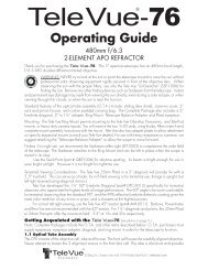
Component Recommendations for Top Performance at Prime Focus<br />
Recommended<br />
Maximum<br />
CCD/film<br />
diagonal<br />
Speed<br />
Focal<br />
Length<br />
Field of View<br />
Camera<br />
Connector<br />
Additional<br />
Spacer to<br />
match 55mm<br />
reference<br />
Accessory Lens<br />
Spacer length<br />
from focuser<br />
drawtube<br />
1<br />
30mm<br />
(APS size DSLR)<br />
f/5.4<br />
540mm<br />
3.2°<br />
T-ring<br />
(TRG-1072)<br />
or<br />
Wide T-Ring<br />
(CWT-2070)<br />
X<br />
X<br />
2.375"<br />
(2) TLD-1000<br />
(1) TLB-0375<br />
2<br />
30mm<br />
(APS size DSLR)<br />
f/4.3<br />
435mm<br />
4.0°<br />
T-ring<br />
(TRG-1072)<br />
or<br />
Wide T-Ring<br />
(CWT-2070)<br />
X<br />
0.8x Reducer<br />
(NPR-1073)<br />
0.5"<br />
TLC-0500<br />
3<br />
40mm<br />
(SBIG STL series<br />
cameras)<br />
f/5.4<br />
540mm<br />
4.2°<br />
SBIG STL Series<br />
(STL-1071)<br />
1.0"<br />
TLD-1000<br />
Large Field<br />
Corrector<br />
(LCL-1069)<br />
1.375"<br />
(1) TLD-1000<br />
(1) TLB-0375<br />
Not<br />
Shown<br />
Apogee<br />
Cameras<br />
with f/5.<br />
4<br />
D2 Lids<br />
540mm<br />
Will vary with<br />
camera<br />
AD2-1110<br />
1.375"<br />
(1) TLD-1000<br />
(1) TLB-0375<br />
Large Field<br />
Corrector<br />
(LCL-1069)<br />
1.375"<br />
(1) TLD-1000<br />
(1) TLB-0375<br />
4<br />
40mm<br />
(35mm SLR/DSLR)<br />
f/5.4<br />
540mm<br />
4.2°<br />
Accessories Key<br />
A. Imaging System Adapter (Supplied Standard)<br />
E. LCL-1069 Large Field Corrector for optimized edge<br />
performance on <strong>NP101</strong>is and NP127is (for big chip sizes).<br />
O. TLA-0250 0.25” long threaded extension<br />
J. STL-1071 SBIG STL series adapter<br />
K. TRG-1072 Standard T-Ring adapter<br />
L. CWT-2070 Canon Wide T Adapter<br />
7<br />
T-ring<br />
(TRG-1072)<br />
or<br />
Wide T-Ring<br />
(CWT-2070)<br />
0.25"<br />
TLA-0250<br />
Large Field<br />
Corrector<br />
(LCL-1069)<br />
1.375"<br />
(1) TLD-1000<br />
(1) TLB-0375<br />
P. TLB-0375 0.375” long threaded extension<br />
R. TLC-0500 0.500” long threaded extension<br />
T. TLD-1000 1.000” long threaded extension<br />
F. NPR-1073 0.8X Reducer
1. Prime focus for APS and smaller size chips in cameras with<br />
55mm chip to T-Ring distance.<br />
2. Prime focus with 0.8X Reducer for APS and smaller size<br />
chips in cameras with 55mm chip to T-Ring distance.<br />
3. Prime focus with SBIG STL series cameras<br />
4. Prime focus with 35mm format SLRs in cameras with 55mm<br />
chip to T-Ring distance.<br />
8
4.1 Adjustable Position End Ring<br />
The tilt of the End Ring to the optical axis can be changed to compensate for any tilt errors you may see in<br />
your photography. The telescope is aligned with the End Ring locked firmly against the end of the draw<br />
tube. In this way you are always assured of a reference point to return to if necessary.<br />
To determine which way to tilt the End Ring, it is necessary to focus on the part of the image that comes<br />
to focus first when racking out the focuser from its “in” position. That will permit adjusting, or “jacking,”<br />
the End Ring “out” to match that focus point in the field.<br />
You will need to remove your camera equipment, including the Imaging System Adapter to adjust the<br />
tilt of the End Ring . Slightly loosen the three Jamb Screws located on the face of the End Ring with the<br />
appropriate Allen key. Then, “jack” the End Ring to the desired position using the appropriate Allen key<br />
Jack Screws. Tighten the Jamb Screws against the End Ring and reinstall your camera. Some trial and<br />
error imaging will be necessary, so it is best to carry out any necessary adjustment during an imaging<br />
session.<br />
4.2 Prime Focus<br />
Prime focus photography involves attaching a camera, without its lens, to the telescope. In this method<br />
the telescope becomes the camera’s lens. In the case of the <strong>NP101</strong>is, it is a 540mm focal length, f/5.4<br />
telephoto. It is the focal length of the telescope in combination with the diagonal dimension of the CCD<br />
chip or film frame that will determine the amount of field your photograph will cover. The shorter the focal<br />
length or larger the diagonal dimension, the greater the field that will be recorded.<br />
The parts necessary for Prime Focus photography are: SLR/DSLR camera body with T-ring, appropriate<br />
T-ring adapter, Extension Spacers, Large Field Corrector (if necessary), Imaging System adapter, telescope.<br />
To obtain the best edge sharpness with 35mm or larger formats, use the Large Field Corrector<br />
(LCL-1069) in the configurations listed below.<br />
The recommendations in the chart and diagrams are specifically for SLR (digital or film) and the Apogee<br />
and SBIG STL series cameras. If you have a different CCD camera with a 35mm or larger format, you will<br />
need to determine the spacer necessary to achieve the optimal distance from the shoulder of the Large Field<br />
Corrector to the CCD chip. Check the <strong>Tele</strong> <strong>Vue</strong> website for on-going camera updates.<br />
To start, you need to know the distance from the chip to the faceplate of the camera. This should<br />
be specified in the camera’s documentation; call your camera’s manufacturer if it is not. Simply subtract<br />
“chip to faceplate” distance from 2.75” to get the spacing required from the Large Field Corrector to your<br />
faceplate, for up to 35mm formats. For larger formats, such as 53mm diagonal, use 2.67” instead of<br />
2.75. Use threaded Imaging System components to bring you as close as possible.<br />
Since there are tolerances in all manufactured parts, it may be necessary to vary the spacing slightly<br />
from the nominally calculated value. Should your star images in the four corners look slightly elongated,<br />
try using the next smallest increment of threaded spacer with either the 0.040” (TLF-0040), 0.080” (TLG-<br />
0080), or both in between the threaded spacers to fine tune the image.<br />
4.2a) To gain more field with chips APS size and smaller, use the 0.8x Reducer (NPR-1073). While the<br />
reducer can be used with larger formats such as 35mm, noticeable vignetting will occur. The standard<br />
technique of “flat fielding” can compensate but requires significant image “stretching.” The arrangement<br />
of parts necessary for Prime Focus photography with the 0.8x Reducer is: camera with T-ring, appropriate<br />
T-ring adapter, NPR-1073, Extension Spacers to minimize draw tube out-travel, Imaging System adapter,<br />
telescope.<br />
4.2b) To gain more magnification, the 2x (PMT-2200) and 4x (PMT-4201) Powermates are recommended<br />
for best performance. Start by inserting the 2” Accessory Adapter into the end of the focuser. (Since increasing<br />
the magnification will reduce the field, the large opening provided by the Imaging System Adapter is<br />
of no benefit.) The arrangement of parts necessary is: camera with a T-ring attached, Powermate with corresponding<br />
T-ring adapter (PTR-2200 or PTR-4201) attached, 3.5” Extension Tube (X3C-0009), telescope.<br />
There are certainly a variety of ways of setting up the <strong>Tele</strong> <strong>Vue</strong>-<strong>NP101</strong>is for photography!<br />
9
5.0 ADDITIONAL ACCESSORIES<br />
5.1 All <strong>Tele</strong> <strong>Vue</strong> telescopes with rack and pinion focusers now permit the photographer to index focus position<br />
to within 0.00005” by means of a digital indicator. Mounting points are provided on top of the focuser<br />
body and end of the draw tube for easy installation of the various Digital Indicator Kits. Using the Digital<br />
Indicator provides a convenient way of finding best focus, returning to it, or checking that it hasn’t changed.<br />
Choose either the 10 Micron (0.0004”) Indicator Kit (LMK-2404) or the 1 micron Indicator Kit (LMF-<br />
2405) depending on the accuracy desired. Both indicators have 0.5” motion ranges and accept an<br />
RS-232 output cable for displaying readout on computer. The 10 foot long RS-232 Output Cable (RSC-<br />
2320) permits remote indicator readout on computer screen via downloadable software from the <strong>Tele</strong> <strong>Vue</strong><br />
website (www.<strong>Tele</strong><strong>Vue</strong>.com). The cable also provides power to the indicator.<br />
5.2 The Focusmate Driver for the <strong>NP101</strong>is (FDF-2004) electronically drives the fine focus knob of the 10:1<br />
Focusmate in steps of approximately 0.0005” per button click. With the button depressed, the motor<br />
drives the Focusmate continuously without vibration transferred to the system. Motor speed is variable.<br />
The motor has a standard phone jack that will accept a cord of any length. Remote control is possible.<br />
Contact <strong>Tele</strong> <strong>Vue</strong> for further details.<br />
6.0 Caring for your <strong>NP101</strong>is<br />
<strong>Tele</strong> <strong>Vue</strong>-<strong>NP101</strong>is requires no special care. Treat it as you would any fine camera lens. Use the lens cap<br />
when the telescope is being stored or not in use. The captive dew shield provides protection from glare,<br />
helps protect the lens from dust or spray blown in by the wind and minimizes dew formation on the lens.<br />
If dew forms on the lens during cold weather, it is best to use a hair dryer (on the lowest setting) to<br />
gently warm it away. A few specks of dust will have no effect on image quality and may be gently blown<br />
off with a squeeze bulb. Do not use compressed air cans to blow dust off optical surfaces.<br />
To prevent dew formation when bringing the scope in from the cold, we advise to close the cold<br />
scope in its case before bringing it into the warm indoors. Do not open the case until the scope has come<br />
up to room temperature.<br />
Fingerprints or oils should be cleaned off the lens surface. Though the anti-reflection coatings are<br />
durable, they can be scratched. The simplest cleaning method is to moisten a very soft, lint-free tissue,<br />
cloth, “Q-Tip” or surgical cotton with a lens or glass cleaner and working in a circular motion, gently whisk<br />
away the stain. Do not apply any solutions directly to the glass surfaces. After every cleaning stroke, use<br />
a fresh applicator. The fewer strokes the better! Any residual “film” will not affect visual performance.<br />
Collimation of your <strong>Tele</strong> <strong>Vue</strong>-<strong>NP101</strong>is has been locked at the factory. With reasonable care it will<br />
remain aligned. However, rough handling can cause misalignment. WARNING: The button head screws<br />
in the front lens cell are filled with epoxy. Loosening these screws will cause misalignment. If necessary,<br />
contact <strong>Tele</strong> <strong>Vue</strong> for re-collimation.<br />
Your star diagonal employs a first-surface mirror. Like all first-surface mirrors, it should be cleaned<br />
only when absolutely necessary. First blow loose dust away with a squeeze bulb. CAUTION: Do not<br />
clean mirror with water or water based cleaners such as Windex or any other commercial lens cleaners;<br />
this is not a lens. All contain too much water and will leave stains. Moisten a “Q-Tip” with pure acetone,<br />
methanol or Isopropyl alcohol, reagent grade. Clean gently using only the weight of the cotton swab.<br />
Use light pressure and never rub. Slight residual stains or dust have no visible effects in observing.<br />
The tube is powder-coated for durability and can be waxed with any nonabrasive car wax. Black<br />
anodized surfaces can be cleaned with Windex. If you have any questions about the care, operation or<br />
performance of your <strong>Tele</strong> <strong>Vue</strong>-<strong>NP101</strong>is, please call us at (845) 469-4551 from 9:30 am to 5:00 pm EST.<br />
10
7.0 Warranty<br />
<strong>Tele</strong> <strong>Vue</strong> telescopes are warranted to be free of manufacturing or workmanship defects for 5 (five) years<br />
from the date of purchase, to the original owner. Please return the warranty card as validation of your<br />
ownership and for easy identification. If your <strong>Tele</strong> <strong>Vue</strong> telescope requires warranty service, please call<br />
<strong>Tele</strong> <strong>Vue</strong> to discuss the problem, upon which you will receive a return authorization. NO RETURNS ARE<br />
ACCEPTED WITHOUT PRIOR AUTHORIZATION.<br />
The warranty does NOT include: collimation, defects caused by mishandling, defects of subjective<br />
nature, or coverage for any telescope purchased through an unauthorized <strong>Tele</strong> <strong>Vue</strong> dealer.<br />
Warranty work will be performed at <strong>Tele</strong> <strong>Vue</strong>’s discretion and may only be performed by <strong>Tele</strong> <strong>Vue</strong><br />
Optics or <strong>Tele</strong> <strong>Vue</strong> authorized agent. The telescope must be shipped in its case with proper inner and<br />
outer packaging. Shipping and insurance charges are the purchaser’s responsibility.<br />
8.0 Specifications<br />
Type<br />
4-element, flat field, APO refractor, Fully Multi-Coated<br />
Clear Aperture 4 inches (101.6mm)<br />
Aperture Gain 211, compared to a 7mm exit pupil<br />
Focal Length 540mm<br />
Focal Ratio f/5.4<br />
Resolution (visual) 1.1 arc-sec. (Dawes Limit for a 4 inch aperture)<br />
Resolution 267 line pairs per mm<br />
(photographic)<br />
Magnification 10x to 270x using <strong>Tele</strong> <strong>Vue</strong> eyepieces<br />
Field, Visual 4.9 o at 10x<br />
Focuser<br />
2.4-inch, rack and pinion type<br />
Diagonal Accepts optional 2-inch 99% reflective dielectric coating, with 1¼” adapter<br />
Finder<br />
Optional Starbeam or 55mm Plössl for 10x, 4.9 o field<br />
Mounting Optional adjustable ring mount or tube rings with ¼-20 tapped holes for<br />
standard photographic tripods or optional <strong>Tele</strong> <strong>Vue</strong> and Vixen mounts<br />
Weight<br />
10.6 lbs. (tube assembly) 19 lbs. in case, 28 lbs. shipping<br />
Length<br />
26-inches (O.T.A. only)<br />
Accessories included as standard: custom fitted case, screw-on lens cover, sliding dew (glare) shield,<br />
2” Accessory Adapter, Imaging Systems Adapter<br />
Tube<br />
Powder-coated aluminum<br />
Specifications subject to change without notice.<br />
11
<strong>Tele</strong> <strong>Vue</strong> recommends choosing low and medium power eyepieces in ratios of field stop diameters. For<br />
example, factors of 1.4 or 2.0. When choosing higher power eyepieces, use ratios of magnification.<br />
Focal<br />
Length<br />
(mm)<br />
Type<br />
Product Code<br />
Apparent<br />
Field (deg)<br />
<strong>Tele</strong> <strong>Vue</strong>-<strong>NP101</strong>/<strong>NP101</strong>is<br />
Field Stop Dia.<br />
(mm)<br />
Eye Relief<br />
(mm)<br />
2" Eyepieces for Wide True Fields<br />
55 Plössl EPL-55.0 50 46.0 38 1.1 9.8 4.88 10.3 4 Y<br />
41 Panoptic EPO-41.0 68 46.0 27 2.1 13.2 4.88 7.7 6 Y<br />
31 Nagler 5 EN5-31.0 82 42.0 19 2.2 17.4 4.46 5.8 6 Y<br />
35 Panoptic EPO-35.0 68 38.7 24 1.6 15.4 4.11 6.5 6 Y<br />
21 Ethos ETH-21.0 100 36.2 15 2.3 25.7 3.84 3.9 - Y<br />
26 Nagler 5 EN5-26.0 82 35.0 16 1.6 20.8 3.71 4.9 6 Y<br />
22 Nagler 4 EN4-22.0 82 31.1 19 1.5 24.5 3.30 4.1 7 Y<br />
27 Panoptic EPO-27.0 68 30.5 19 1.0 20.0 3.24 5.1 6 Y<br />
17 Ethos ETH-17.0 100 29.6 15 1.6 31.8 3.14 3.2 - Y<br />
20 Nagler 5 EN5-20.0 82 27.4 12 1.0 27.0 2.91 3.7 6 Y*<br />
17 Nagler 4 EN4-17.0 82 24.3 17 1.6 31.8 2.58 3.2 7 Y<br />
1¼" Eyepieces for Wide True Fields<br />
40 Plössl EPL-40.0 43 27.0 28 0.4 13.5 2.87 7.5 4 Y<br />
32 Plössl EPL-32.0 50 27.0 22 0.4 16.9 2.87 6.0 4 Y<br />
24 Panoptic EPO-24.0 68 27.0 15 0.5 22.5 2.87 4.5 6 Y*<br />
13 Ethos ETH-13.0 100 22.3 15 1.3 41.5 2.37 2.4 - Y<br />
16 Nagler 5 EN5-16.0 82 22.1 10 0.4 33.8 2.35 3.0 6 N<br />
19 Panoptic EPO-19.0 68 21.3 13 0.4 28.4 2.26 3.6 6 Y*<br />
25 Plössl EAP-25.0 50 21.2 17 0.3 21.6 2.25 4.7 4 N<br />
17.3 Delos EDL-17.3 72 21.2 20 0.9 31.2 2.25 3.2 - Y<br />
18.2 DeLite EDE-18.2 62 19.1 20 0.5 29.7 2.03 3.4 - Y<br />
10 Ethos ETH-10.0 100 17.7 15 1.1 54.0 1.88 1.9 - Y<br />
13 Nagler 6 EN6-13.0 82 17.6 12 0.4 41.5 1.87 2.4 7 Y*<br />
14 Delos EDL-14.0 72 17.3 20 0.9 38.6 1.84 2.6 - Y<br />
20 Plössl EAP-20.0 50 17.1 14 0.2 27.0 1.81 3.7 4 N<br />
12 Nagler 4 EN4-12.0 82 17.1 17 1.0 45.0 1.81 2.2 6 Y<br />
1¼" Eyepieces for Medium Powers<br />
12 Delos EDL-12.0 72 15.0 20 0.9 45.0 1.59 2.2 - Y<br />
11 Nagler 6 EN6-11.0 82 14.9 12 0.4 49.1 1.58 2.1 7 Y*<br />
10 Delos EDL-10.0 72 12.7 20 0.9 54.0 1.35 1.9 - Y<br />
15 Plössl EAP-15.0 50 12.6 10 0.2 36.0 1.34 2.8 4 N<br />
9 Nagler 6 EN6-09.0 82 12.4 12 0.4 60.0 1.32 1.7 7 Y*<br />
11 DeLite EDE-11.0 62 11.7 20 0.4 49.1 1.24 2.1 - Y<br />
11 Plössl EAP-11.0 50 9.1 8 0.1 49.1 0.97 2.1 4 N<br />
1¼" Eyepieces for Higher Powers<br />
8 Ethos ETH-08.0 100 13.9 15 1.0 67.5 1.47 1.5 - Y<br />
6 Ethos ETH-06.0 100 10.4 15 1.0 90.0 1.10 1.1 - Y<br />
8 Delos EDL-08.0 72 9.9 20 1.0 67.5 1.05 1.5 - Y<br />
7 Nagler 6 EN6-07.0 82 9.7 12 0.5 77.1 1.03 1.3 7 Y*<br />
4.7 Ethos SX ETH-04.7 110 8.9 15 1.3 114.9 0.95 0.9 - Y<br />
6 Delos EDL-06.0 72 7.6 20 1.0 90.0 0.81 1.1 - Y<br />
7 DeLite EDE-07.0 62 7.5 20 0.5 77.1 0.80 1.3 - Y<br />
3.7 Ethos SX ETH-03.7 110 7.0 15 1.1 145.9 0.75 0.7 - Y<br />
5 Nagler 6 EN6-05.0 82 7.0 12 0.5 108.0 0.74 0.9 7 Y*<br />
8 Plössl EAP-08.0 50 6.5 6 0.1 67.5 0.69 1.5 4 N<br />
4.5 Delos EDL-04.5 72 5.6 20 1.1 120.0 0.59 0.8 - Y<br />
3.5 Nagler 6 EN6-03.5 82 4.8 12 0.5 154.3 0.51 0.7 7 Y*<br />
3.5 Delos EDL-03.5 72 4.4 20 1.1 154.3 0.47 0.7 - Y<br />
2.5 Nagler 6 EN6-02.5 82 3.4 12 0.5 216.0 0.36 0.5 7 Y*<br />
1¼" Zoom Eyepieces for Medium and Higher Powers<br />
Weight<br />
(lb.)<br />
6-3 Nagler Zoom ENZ-0306 50 5.1-2.6 10 0.3<br />
Mag.<br />
90.0-<br />
180.0<br />
True<br />
Field<br />
(deg)<br />
0.54-<br />
0.28<br />
Exit<br />
Pupil<br />
(mm)<br />
1.1-<br />
0.6<br />
# of<br />
Elem.<br />
Dioptrx<br />
Ready<br />
5 N<br />
NOTE: True Field in degrees = (Field Stop dia./<strong>Tele</strong>scope Focal Length) X 57.3°<br />
*Indicates additional Dioptrx Adapter required