GF-Quad Dolly Manual - Grip Factory Munich GmbH
GF-Quad Dolly Manual - Grip Factory Munich GmbH
GF-Quad Dolly Manual - Grip Factory Munich GmbH

You also want an ePaper? Increase the reach of your titles
YUMPU automatically turns print PDFs into web optimized ePapers that Google loves.
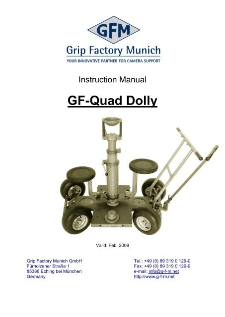
Instruction <strong>Manual</strong><br />
<strong>GF</strong>-<strong>Quad</strong> <strong>Dolly</strong><br />
Valid: Feb. 2008<br />
<strong>Grip</strong> <strong>Factory</strong> <strong>Munich</strong> <strong>GmbH</strong> Tel.: +49 (0) 89 319 0 129-0<br />
Fürholzener Straße 1 Fax: +49 (0) 89 319 0 129-9<br />
85386 Eching bei München e-mail: info@g-f-m.net<br />
Germany http://www.g-f-m.net
Contents<br />
GENERAL INFORMATION ABOUT THE <strong>GF</strong>-QUAD DOLLY ............................................................... 2<br />
<strong>GF</strong>-QUAD DOLLY TECHNICAL SPECIFICATIONS ............................................................................. 4<br />
<strong>GF</strong>-QUAD DOLLY COMPONENTS ........................................................................................................ 4<br />
INTRODUCTION ..................................................................................................................................... 5<br />
SAFETY GUIDELINES ........................................................................................................................... 6<br />
OPERATION AND ASSEMBLY INSTRUCTIONS ................................................................................. 8<br />
1 GROUND CONDITIONS ................................................................................................................ 8<br />
2 CHANGING THE WHEELS ............................................................................................................ 8<br />
3 STEERING ROD ASSEMBLY AND FUNCTIONS ...................................................................... 11<br />
4 STEERING MODE SELECTION .................................................................................................. 13<br />
5 SETTING THE TURN ANGLE ..................................................................................................... 15<br />
6 MOUNTING ACCESSORIES ....................................................................................................... 16<br />
6.1 EURO-ADAPTER PLATE ............................................................................................................ 16<br />
6.2 TURNSTILE MOUNT ................................................................................................................. 17<br />
6.3 EURO-ADAPTER BASED ACCESSORIES ..................................................................................... 17<br />
6.4 SEAT ARM EXTENSIONS AND SEATS ......................................................................................... 18<br />
6.5 SIDE PLATFORMS .................................................................................................................... 19<br />
6.6 PUSH BAR .............................................................................................................................. 20<br />
6.7 TRIPOD .................................................................................................................................. 21<br />
7 <strong>GF</strong>-QUAD DOLLY BRAKES ........................................................................................................ 23<br />
8 TRANSPORTING THE <strong>GF</strong>-QUAD DOLLY .................................................................................. 23<br />
9 SERVICE AND MAINTENANCE .................................................................................................. 24<br />
- 1 -
General information about the <strong>GF</strong>-<strong>Quad</strong> <strong>Dolly</strong><br />
The <strong>GF</strong>-<strong>Quad</strong> is a lightweight dolly that because of its flexibility, mobility and<br />
innovative features, provides a wide range of functions for camera movement on set.<br />
Flexibility on set:<br />
As a standard, the <strong>GF</strong>-<strong>Quad</strong> <strong>Dolly</strong> is equipped with pneumatic wheels but can,<br />
without tools, easily be transformed into a track dolly.<br />
For use on track there is a choice of skateboard or track wheels.<br />
Ground surface use On track<br />
Mobility on set:<br />
The <strong>GF</strong>-<strong>Quad</strong> <strong>Dolly</strong> is equipped with 2 steering axles both of which have corrected<br />
steering geometry. These are the key to providing a choice of the 3 different steering<br />
modes.<br />
Front wheel steering – 4 wheel steering – Rear wheel steering<br />
The 4 wheel steering is especially useful<br />
for narrow curved and circular moves, enabling<br />
a small circle of 80cm / 31” diameter.<br />
Furthermore, the front steering axle may be<br />
locked at any angle within its range, allowing a<br />
repeatability of curved or straight moves.<br />
- 2 -
Functionality on set:<br />
The <strong>GF</strong>-<strong>Quad</strong> <strong>Dolly</strong> has numerous possibilities to connect various mounts and<br />
accessories. There are 5 connection positions for mounting a Euro-adapter plate and<br />
also 3 dedicated holes to accommodate a camera tripod. With these features you are<br />
well equipped to tackle your next shoot whether it be on location or in the studio.<br />
Euro-adapter connections Tripod connection<br />
Connection positions<br />
Additional Features:<br />
<strong>GF</strong>-<strong>Quad</strong> <strong>Dolly</strong> Platform → Lightweight aluminium construction: High<br />
stability, low weight<br />
Telescopic Pushbar → Mountable at both ends of dolly and with<br />
adjustable width for track and doorway shots<br />
Steering rod → 3 fixed positions via locking pin.<br />
Horizontal, vertical und 60° settings.<br />
Step-less angle adjustment by removing<br />
locking pin and using locking lever<br />
Brakes on pneumatic and track wheels<br />
Maintenance free 4 wheel steering mechanism<br />
Light moving steering<br />
Compact dimensions → The 75cm / 29“ wide dolly allows easy<br />
manoeuvring through tight doorways.<br />
- 3 -
<strong>GF</strong>-<strong>Quad</strong> <strong>Dolly</strong> Technical Specifications<br />
Dimensions and weights<br />
With pneumatic wheels*<br />
With track wheels*<br />
L x W/ kg /lbs:<br />
L x W/ kg /lbs<br />
With skateboard wheels* L x W/ kg /lbs<br />
Without additional platforms With additional platforms<br />
122 cm x 75 cm / 43 kg<br />
48 inch x 29 inch / 94lbs<br />
121 cm x 78 cm / 40 kg<br />
47 inch x 30 inch / 88lbs<br />
120 cm x 74 cm / 35 kg<br />
47 inch x 29 inch / 77lbs<br />
Max. working load** [kg / lbs]: 250 kg / 550lbs<br />
* Weight includes: dolly platform und steering rod<br />
** Maximum allowed working load on dolly platform consists of:<br />
2 pers, accessoires and camera<br />
<strong>GF</strong>-<strong>Quad</strong> <strong>Dolly</strong> components<br />
Seat arm extension<br />
Connection for<br />
Euro-adapter<br />
ür<br />
Euroadapterplatte<br />
Locking lever for<br />
steering<br />
transmission<br />
Euro-adapter<br />
Connection holes for additional platforms<br />
Brakes<br />
Removable<br />
pneumatic<br />
wheel<br />
<strong>GF</strong>-<strong>Quad</strong> <strong>Dolly</strong> components<br />
Seat<br />
122 cm x 105 cm / 47 kg<br />
48 inch x 41 inch / 103lbs<br />
121 cm x 105 cm / 44 kg<br />
47 inch x 41 inch / 96lbs<br />
120 cm x 105 cm / 39 kg<br />
47 inch x 41 inch / 85lbs<br />
Telescopic<br />
pushbar<br />
Steering rod<br />
Turnstile mount<br />
Removable<br />
pneumatic<br />
wheel<br />
- 4 -
Introduction<br />
We would like to thank you for choosing the <strong>GF</strong>-<strong>Quad</strong> <strong>Dolly</strong> and also for the trust you<br />
place in us by making this decision.<br />
To enable you to utilize all the features and options that are available, and above all<br />
to operate in a safe and responsible manner, there some rules and guidelines that<br />
must be followed.<br />
The assembly instructions and safety guidelines must be read and<br />
understood before set-up or operation.<br />
The dolly may only be used in accordance with the manufacturer‟s instruction<br />
manual. The manufacturer‟s technical specifications and limits must be adhered to at<br />
all times and in no way exceeded.<br />
The manufacturer accepts no liability for damages or injuries, for incidents or<br />
accidents occurring due to negligence by the operator or misuse of the dolly or<br />
disregarding the instruction manual.<br />
- 5 -
Safety Guidelines<br />
Condition of equipment:<br />
Before using the <strong>GF</strong>-<strong>Quad</strong> <strong>Dolly</strong> check to ensure that all components (removable<br />
wheels, steering rod, steering axles, turnstile mount, Euro-adapter, tripod etc) are<br />
secured correctly and that the respective safety elements are in place.<br />
To avoid unwanted platform movement and instability, ensure that the 4 pneumatic<br />
wheels are filled to the manufacturers recommend tire pressure of 2,8Bar / 40PSI.<br />
In cases where the dolly is used with lower pressure, ensure that all 4 tires have the<br />
same pressure.<br />
To ensure an optimal working situation, only original <strong>GF</strong>M parts and accessories<br />
should be used with the <strong>GF</strong>-<strong>Quad</strong> <strong>Dolly</strong>.<br />
Working surface conditions and payload:<br />
Ensure that the ground surface is stable and cannot give way. The ground surface<br />
must be stable enough to support at least 500 kg/m2 = 1100 lbs/ sq yard<br />
In general the working surface must be flat, horizontal, solid enough to take the<br />
respective load and free from obstructions. Should these conditions not be available<br />
naturally then they must be created. In such cases the dolly must be used on track<br />
and the track must be assembled on a stable underlay. The correct underlay must be<br />
used and it must be ensured that the track and underlay are secured against moving,<br />
slipping and collapse. Ensure that the underlay meets the specified weight<br />
requirements and stability requirements and is laid in a manner that does not cause<br />
the operators to trip over.<br />
When using a track system the assembly instructions and safety guidelines must be<br />
read and understood before set-up or operation.<br />
Loading the <strong>Dolly</strong>:<br />
When loading the <strong>GF</strong>-<strong>Quad</strong> <strong>Dolly</strong> it is important to achieve an equal distribution of<br />
weight. Avoid one sided or off-set payloads at either side or end of the main dolly<br />
platform and also on the extra side platforms.<br />
Loading the dolly equally reduces the risk of tipping it over and ensures a safer and<br />
more comfortable working environment.<br />
The maximum working load on the <strong>GF</strong>-<strong>Quad</strong> <strong>Dolly</strong> is 250 kg / 550 lbs and<br />
consists of:<br />
2 pers, accessories and camera<br />
The maximum working load may not be exceeded!<br />
- 6 -
Operating the dolly:<br />
When operating the dolly, banging or crashing into objects should be avoided.<br />
Curved movements should be made at no more than a walking pace. The same<br />
applies for track moves. Furthermore track underlay and support material must be<br />
laid in a manner that does not cause the operators to fall or trip over it.<br />
<strong>Dolly</strong> transportation:<br />
When transporting the dolly, all temporarily assembled accessories should be<br />
removed from the dolly and the steering rod should folded flat onto the platform.<br />
To avoid damage and injury all loose objects must be secured and tied down to avoid<br />
any unwanted movement caused by abrupt braking or similar occurrences.<br />
- 7 -
Operation and assembly instructions<br />
The following instructions describe the handling and assembly of accessories on the<br />
<strong>GF</strong>-<strong>Quad</strong> <strong>Dolly</strong>.<br />
1 Ground conditions<br />
Before using the <strong>GF</strong>-<strong>Quad</strong> <strong>Dolly</strong>, the ground and surface conditions should be<br />
inspected to ensure that they meet with the requirements as per the Safety<br />
Guidelines and in turn the respective wheel type can be selected. For this<br />
purpose there is a selection of wheel types available for the <strong>GF</strong>-<strong>Quad</strong> <strong>Dolly</strong>:<br />
Ground / floor operation: Track operation:<br />
Pneumatics Track wheels Skateboard wheels<br />
2 Changing the wheels<br />
Assembly:<br />
As a standard, the pneumatic wheels are equipped with axles.<br />
Attention: The <strong>GF</strong>-<strong>Quad</strong> <strong>Dolly</strong> has a rotation restrictor on the wheel<br />
axles which also defines the exact assembly position of<br />
the wheel. So when connecting, ensure that the flat part<br />
on the wheel axle joins with the flat counterpart on the axle<br />
connection on the base.<br />
Axle<br />
Rotation restrictor<br />
(Flat part und<br />
counterpart)<br />
Axle connection<br />
- 8 -
To mount the wheels proceed as follows:<br />
By holding the knurled knob, insert the axle<br />
into the axle connection as far as it will go.<br />
Pressing the axle inwards, rotate it until<br />
the flat rotation restrictor on the axle meets with<br />
the flat rotation restrictor on the axle connection<br />
and insert fully.<br />
Locking pin<br />
Montage der Luftreifen<br />
Mounting the pneumatic wheel<br />
An alternative method is to align the 2 flat rotation restrictors<br />
in advance and insert fully until connected completely.<br />
Wheel axle<br />
with knurled<br />
knob<br />
Pneumatic wheel<br />
Wheel<br />
brake<br />
Tip: The wheels are mounted correctly when:<br />
The flat rotation restrictor on the axle is covered by the flat rotation<br />
restrictor on the axle connection<br />
The locking pin is inserted fully (audible “click”)<br />
The axle cannot rotate or be removed (unless by disengaging the<br />
locking pin)<br />
Attention: Prior to mounting the pneumatic wheels, ensure that the<br />
wheel brakes are opened fully. It‟s not possible to mount<br />
the pneumatic wheels when the brake is in the locked<br />
position!<br />
- 9 -
When assembling the track or skateboard wheels it is easier to recognize the rotation<br />
restrictor on the track wheel axles. To mount the track wheels proceed as follows:<br />
Track wheel axle<br />
Insert the track wheel shaft into the shaft connector on the track wheel<br />
unit, checking that the safety pin is inserted fully. Tip: when the pin slips<br />
into place is makes an audible click!<br />
Track wheel<br />
shaft<br />
Mounting the track wheels<br />
Disassembly:<br />
To remove the wheels, release the locking pin by pulling it away from<br />
the axle connection. At the same time remove the respective wheel<br />
axle.<br />
Removing the track wheel<br />
Track wheel<br />
shaft connector<br />
- 10 -
3 Steering rod assembly and functions<br />
By correctly using the steering rod it is possible to manoeuvre the <strong>GF</strong>-<strong>Quad</strong><br />
<strong>Dolly</strong> with extreme precision. To mount and adjust the steering rod, please<br />
proceed as follows:<br />
Position the forked steering rod centrally on the steering rod mount<br />
located on the rear axle of the dolly.<br />
Connect the steering rod to the mount by inserting the locking lever and<br />
screwing it into the threaded sleeve on the steering rod fork.<br />
Attention: To operate correctly, when connecting the steering rod,<br />
ensure that the threaded sleeve insert is always on the<br />
opposite side of the rod to the locking lever.<br />
Steering rod mount<br />
with connection hole<br />
and 3, angle<br />
positioning holes<br />
Threaded sleeve<br />
insert on the<br />
steering rod fork<br />
Mounting the steering rod<br />
Locking lever<br />
Safety pin hole for<br />
fixed angle positions<br />
To enhance the <strong>GF</strong>-<strong>Quad</strong> <strong>Dolly</strong>‟s flexibility there are 3 further steering<br />
applications<br />
Safety pin, in<br />
storage position<br />
Application 1, fixed push bar function:<br />
By connecting with the safety pin, there are 3 set angles (0°, 60° or<br />
90°) were the steering rod can be used like a push bar. Proceed as<br />
follows:<br />
Loosen the steering rod by undoing the locking lever until<br />
the steering rod is easily repositioned.<br />
Fix the steering rod at 1 of the 3 positions by inserting the<br />
safety pin at 0°, 60° oder 90° and lock securely by<br />
retightening the locking lever.<br />
- 11 -
Steering rod<br />
fixed at 90°<br />
Steering rod<br />
fixed at 60°<br />
Steering rod<br />
fixed at 0°<br />
Steering rod fixed positions<br />
Steering rod fixed at 60° and<br />
secured with safety pin<br />
Application 2, step-less angle adjustment of the steering rod:<br />
When the safety pin is removed and placed in the storage position, the<br />
locking lever, which also functions as the connection element between<br />
the steering rod and mount, can be used to fix the steering rod at a<br />
range of required angles.<br />
Proceed as follows:<br />
Insert the safety pin into the storage position hole on the steering<br />
rod.<br />
Move the loosened steering rod to the required position and<br />
lock securely by retightening the locking lever.<br />
Application 3, loosened steering rod:<br />
If required the steering rod can be used in a freely adjustable, loosened<br />
manner.<br />
Proceed as follows:<br />
Insert the safety pin into the storage position hole on the steering<br />
rod.<br />
Loosen the steering rod by undoing the locking lever so that the<br />
steering rod moves freely.<br />
- 12 -
4 Steering mode selection<br />
With the <strong>GF</strong>-<strong>Quad</strong> <strong>Dolly</strong>, 3 steering modes can be selected from a central<br />
position. The changeover from one mode to the other is a simple matter of<br />
moving a lever. The lever is located between the rear axle and steering axle.<br />
Switch lever location<br />
Attention: The switch lever can only be<br />
activated, when all 4 wheels are<br />
pointed in a straight line.<br />
(neutral position, wheels not turned).<br />
Tip: The different steering modes<br />
are displayed on instruction signs<br />
found on the steering rod.<br />
Instructions signs on steering rod<br />
Switch<br />
lever<br />
- 13 -
To change the steering mode, proceed as follows:<br />
Place the steering rod in the neutral position so that all the<br />
wheels are in a straight line and not turned<br />
Move the switch lever into the required position (switch position<br />
1, 2 or 3).<br />
Attention: In rear wheel mode (switch position 1) the front axle is<br />
blocked and in front wheel mode (switch position 3) the<br />
rear axle is blocked. Upon selecting the requested<br />
steering mode, check to make sure the respective axle is<br />
blocked.<br />
Steering modes<br />
- 14 -
5 Setting the turn angle<br />
By using the turn angle lock off on the front axle, the <strong>GF</strong>-<strong>Quad</strong> <strong>Dolly</strong>„s steering<br />
angle can be set to enable repeatable curved and straight dolly moves.<br />
Please follow these steps:<br />
To select the turn angle, change to<br />
either front wheel steering or 4 wheel<br />
steering mode (see page 13, steering<br />
mode selection)<br />
Attention: In rear wheel steering<br />
mode the front axle is<br />
blocked so it is not<br />
possible to lock the turn<br />
angle.<br />
Set the required turn angle by adjusting the<br />
steerage transmission accordingly.<br />
Fix the turn angle by locking the steerage<br />
transmission with the locking lever.<br />
Locking lever for turn<br />
angle lock off<br />
Setting the turn angle<br />
When a turn angle is selected and the dolly is operated under load (max.<br />
payload 250kg / 550lbs) the speed of the movement must be adjusted to<br />
ensure that the dolly cannot tip over.<br />
- 15 -
6 Mounting accessories<br />
6.1 Euro-adapter plate<br />
To enable the fitting of various camera<br />
mounting accessories such as risers, ball<br />
and off-set adapters etc. there are 5<br />
positions on the <strong>GF</strong>-<strong>Quad</strong> <strong>Dolly</strong> platform<br />
to mount a Euro-adapter.<br />
Please proceed as follows:<br />
Euro-adapter plate<br />
M 10 Socket Bolts<br />
Connections for Euro-adapter plate<br />
From underneath the dolly, insert 3 x M10 socket bolts consecutively<br />
through the platform and into the Euro-adapter plate, tightening them<br />
with the sized 10 Allen Key. Ensure that the Euro-adapter plate is<br />
positioned correctly in the fitting and that the bolts are tightened<br />
securely.<br />
Tip: To simplify the assembly of the Euro-adapter, stand the<br />
dolly lengthwise , balanced on the sides of 2 wheels.<br />
In this case, make sure the wheels are not turned but<br />
rather aligned in a straight line so the dolly cannot topple<br />
over.<br />
Mounting the Euroadapter<br />
Euro-adapter<br />
- 16 -
6.2 Turnstile Mount<br />
The turnstile mount allows the camera operator and assistant to assemble 2<br />
seats on the dolly platform and to rotate 360° around the central Euro-adapter.<br />
Further camera positions can be achieved by mounting risers, ball or off-set<br />
adapters etc.<br />
To assemble, please proceed as follows:<br />
To assemble the turnstile mount please proceed in the same manner as<br />
described in § 6.1 on page 16. The turnstile mount is connected in the<br />
same manner as the Euro-adapter plate and secured from underneath<br />
the platform with the respective bolts.<br />
6.3 Euro-adapter based accessories<br />
Locking Lever<br />
Locking ring<br />
Assembling the turnstile mount and adjustable riser<br />
M 10 Socket Bolts<br />
Turnstile Mount<br />
As described in § 6.1 „Euro-adapter plate“, the Euro-adapter serves as a<br />
connection for various camera mounts such as the <strong>GF</strong>M Adjustable Riser.<br />
To assemble, please proceed as follows:<br />
Open the locking ring at the bottom of the adjustable riser and fit the<br />
riser onto the Euro-adapter so that it sits correctly.<br />
By turning the locking handle, close the locking ring until the riser is<br />
locked securely to the Euro-adapter and all play in the fitting is<br />
removed.<br />
- 17 -
6.4 Seat arm extensions and seats<br />
To provide sitting positions on the <strong>GF</strong>-<strong>Quad</strong> <strong>Dolly</strong>, various seat arm<br />
extensions can be connected to the turnstile mount. Please proceed as<br />
follows:<br />
!<br />
Seat arm extensions can be mounted on the connection pins found on<br />
either end of the turnstile mount and locked securely with the respective<br />
locking bolt/knob.<br />
The seats are mounted by connecting the pin on the underside<br />
of the seat into respective fitting in the seat arm and locked securely<br />
with the respective locking bolt/knob.<br />
Attention: When connecting or joining seat arms, do not over extend<br />
or over load them. Abide by the safety guidlines laid down<br />
in the Seat Arm Extension Guidelines<br />
When operating the <strong>GF</strong>-<strong>Quad</strong> <strong>Dolly</strong> ensure that the<br />
dolly payload is evenly distributed!<br />
Mounting the seat arm extensions<br />
Seat arm<br />
connection<br />
pins<br />
Seat arm<br />
extension<br />
Locking<br />
bolt/knob<br />
- 18 -
6.5 Side platforms<br />
Additional side platforms can be used to extend the size of the <strong>GF</strong>-<strong>Quad</strong> <strong>Dolly</strong>.<br />
Please proceed as follows:<br />
Insert the 2 side platform shafts into the 2 connection holes for<br />
additional side platforms found on each side of the main dolly platform.<br />
Attention: The rubber coated side of the platform should be pointing<br />
upwards as per the main platform.<br />
Secure the side platform to the dolly by engaging the locking latch with<br />
the locking hook and tighten securely.<br />
Attention: By adding the 2 side platforms, the width of the dolly is<br />
increased. During use, the operators should be careful<br />
that they don‟t accidently trip over them.<br />
Avoid loading weights or allowing people to stand on the<br />
outside rim of the platforms. Without the respective<br />
weight to counterbalance this, the dolly may tip over.<br />
To avoid collisions, remove the platforms in narrow<br />
passages with a minimum width of 1,05m.<br />
Connection holes for<br />
additional side<br />
platforms<br />
Latch hook Locking latch<br />
Mounting the side platforms<br />
Side platform<br />
- 19 -
6.6 Push bar<br />
The push bar provides the means to better control faster dolly movements. As<br />
the width of the push bar is adjustable, it can be set at the right width for<br />
narrow doorway shots or fast tracking moves.<br />
To mount the push bar on the dolly please proceed as follows:<br />
Insert the push bar into the respective connection holes found at either<br />
the front or rear end of the dolly.<br />
Secure the push bar with the 2 locking knobs/bolts to avoid unwanted<br />
play or removal .<br />
Positioning and securing the push bar<br />
Connection<br />
holes for<br />
push bar<br />
When using the dolly with push bar in doorways or passages narrower than<br />
1,05m the push bar should either be removed or set in the narrowest position<br />
to avoid a collision.<br />
To adjust the push bar, please proceed as follows:<br />
Locking<br />
knob/bolt<br />
Remove the locking pin by firstly unscrewing it from the bar and then by<br />
pressing and holding down the release button to take it out of the hole.<br />
Extend the push bar until, both the hole in the inner and the outer tube<br />
overlap.<br />
- 20 -
6.7 Tripod<br />
Secure the rod by inserting the locking pin and screwing it into place.<br />
Adjusting the push bar<br />
The 3 tripod connection holes found on the <strong>GF</strong>-<strong>Quad</strong> <strong>Dolly</strong>‟s main platform<br />
provide 2 methods to mount a tripod:<br />
Procedure for method 1:<br />
The tripod is placed in the tripod leg fittings and secured.<br />
Bolt the tripod leg fittings to the dolly, securing them from<br />
underneath the platform with the respective M 10 cap screw then<br />
hand tighten with the sized 10 Allen Key.<br />
When the fittings are in position, position the 3 tripod legs.<br />
Locking<br />
pin<br />
Retracted<br />
push bar<br />
Extended<br />
push bar<br />
Upon placing the 3 tripod legs in the fittings on the dolly, secure<br />
each one with the locking fasteners turning each of the 2<br />
locking screws until hand tight.<br />
- 21 -
Procedure for method 2:<br />
The tripod spikes are fitted directly into the connection holes on the<br />
main platform.<br />
Ensure that the tripod is fitted with spikes.<br />
Place the tripod legs / spikes in the connection holes.<br />
Secure the tripod to the dolly with a lashing strap or similar to<br />
avoid accidental tipping.<br />
Tripod leg<br />
fastener<br />
Tripod leg<br />
fitting<br />
Tripod assembly options<br />
- 22 -
7 <strong>GF</strong>-<strong>Quad</strong> <strong>Dolly</strong> brakes<br />
To avoid unwanted movement or rolling of the <strong>GF</strong>-<strong>Quad</strong> <strong>Dolly</strong>, there are 2<br />
brakes located on the front wheel axle to brake the standard pneumatic<br />
wheels. The track wheels also have integrated brakes.<br />
Pneumatic wheel brakes<br />
By turning the wing nut, the brake<br />
pressure can be applied or released.<br />
Ensure that both brakes are secured<br />
with equal pressure on each side of the<br />
front axle.<br />
Attention: Prior to assembling<br />
the pneumatic<br />
Wing nut for<br />
wheel brake<br />
wheels, ensure that both brakes are Pneumatic wheel brake<br />
opened fully. If a brake is not opened<br />
fully, the wheel cannot be mounted!<br />
Track wheel brakes<br />
By turning the wing nut, the brake<br />
pressure can be applied or released.<br />
As opposed to the pneumatic wheels,<br />
track wheel brakes are located on each<br />
wheel unit allowing the front and rear<br />
axles to be locked.<br />
8 Transporting the <strong>GF</strong>-<strong>Quad</strong> <strong>Dolly</strong><br />
Wing nut lock<br />
For transportation, remove all lose accessories<br />
such as seats, seat arms, camera mounts etc.<br />
Track wheel brake<br />
To keep the dolly as compact as possible, fold the Transport position<br />
steering rod onto the platform by removing the<br />
locking pin and loosening the locking lever.<br />
Attention: When transporting any items<br />
in vehicles, all lose objects<br />
must be strapped down with<br />
lashing straps etc. and secured<br />
against unwanted shifting.<br />
Compact transport<br />
- 23 -
9 Service and maintenance<br />
The <strong>GF</strong>-<strong>Quad</strong> <strong>Dolly</strong> and accessories should be inspected at regular intervals,<br />
checking for wear and tear etc. Check that all locking bolts etc are secure. All<br />
4 pneumatic wheels should have the same pressure. The manufacturer<br />
recommends tire pressure of 40 psi / 2,8 bar.<br />
Should the wheels / wheel axles need to be realigned it is a simple and fast<br />
adjustment:<br />
Place the dolly on its side, balanced on the side of 2 pneumatic wheels.<br />
Take the necessary precautions to ensure that the dolly cannot fall<br />
over.<br />
Loosen the adjustment screw on the adjustable connection rod (<br />
between front and rear axles). Make sure the wheels are aligned and<br />
sitting on perfectly level floor or equivalent.<br />
When the wheels are perfectly aligned, tighten the screw securely.<br />
As an alternative to this method the dolly can be turned upside down and<br />
supported so that the wheels are off the ground. Remove 2 wheels on 1 side<br />
of the dolly. Loosen the adjustment screw on the adjustable connection rod.<br />
With a suitably long spirit level or straight edge, align the 2 wheel connections<br />
and retighten the adjustment screw on the adjustable connection rod.<br />
Let the good times roll with your<br />
<strong>GF</strong>-<strong>Quad</strong> <strong>Dolly</strong>!<br />
Technical specifications are subject to change without prior notice!<br />
- 24 -