10010_XHD_Operators_.. - z3m.net
10010_XHD_Operators_.. - z3m.net
10010_XHD_Operators_.. - z3m.net
- No tags were found...

Create successful ePaper yourself
Turn your PDF publications into a flip-book with our unique Google optimized e-Paper software.
OPERATOR’S MANUAL<br />
FOR THE<br />
MANTIS MODEL <strong>10010</strong> <strong>XHD</strong><br />
50-TON DIESEL-POWERED,<br />
HYDRAULICALLY-OPERATED<br />
CRAWLER CRANE
TABLE OF CONTENTS<br />
1. OVERVIEW . . . . . . . . . . . . . . . . . . . . . . . . . . . . . . . . . . . . . . . . . . . . . . . . . . .1<br />
Manual Organization . . . . . . . . . . . . . . . . . . . . . . . . . . . . . . . . . . . . . . . . . .1<br />
Operator Alerts . . . . . . . . . . . . . . . . . . . . . . . . . . . . . . . . . . . . . . . . . . . . . .2<br />
Directional References . . . . . . . . . . . . . . . . . . . . . . . . . . . . . . . . . . . . . . . .2<br />
Capacity Limits and General Conditions . . . . . . . . . . . . . . . . . . . . . . . . . . .2<br />
Lubrication and Maintenance . . . . . . . . . . . . . . . . . . . . . . . . . . . . . . . . . . . .3<br />
2. DASH/CONTROL PANELS . . . . . . . . . . . . . . . . . . . . . . . . . . . . . . . . . . . . . . . .5<br />
Engine Controls . . . . . . . . . . . . . . . . . . . . . . . . . . . . . . . . . . . . . . . . . . . . .6<br />
Swing Right/Left Controls . . . . . . . . . . . . . . . . . . . . . . . . . . . . . . . . . . . . . .8<br />
Telescope Out/In Control; Boom Hoist Control . . . . . . . . . . . . . . . . . . . . . . .9<br />
Winch Controls . . . . . . . . . . . . . . . . . . . . . . . . . . . . . . . . . . . . . . . . . . . . .10<br />
Controlled Freefall Operation (Option) . . . . . . . . . . . . . . . . . . . . . . . . . . . .12<br />
Travel Controls; Tracks Extend/Retract Switch . . . . . . . . . . . . . . . . . . . . . .13<br />
Auxiliary Equipment Controls . . . . . . . . . . . . . . . . . . . . . . . . . . . . . . . . . . .14<br />
Other Operator Controls . . . . . . . . . . . . . . . . . . . . . . . . . . . . . . . . . . . . . .16<br />
3. LOAD MOMENT INDICATOR/ANTI-TWO-BLOCK SYSTEM . . . . . . . . . . . . . .19<br />
Load Moment Indicator . . . . . . . . . . . . . . . . . . . . . . . . . . . . . . . . . . . . . . .19<br />
Load Chart Selection & Load Moment Indicator Setting . . . . . . . . . . . . . . .19<br />
Anti-Two-Block (A2B) . . . . . . . . . . . . . . . . . . . . . . . . . . . . . . . . . . . . . . . .20<br />
4. ENGINE OPERATION . . . . . . . . . . . . . . . . . . . . . . . . . . . . . . . . . . . . . . . . . .21<br />
Alarm Systems . . . . . . . . . . . . . . . . . . . . . . . . . . . . . . . . . . . . . . . . . . . . .21<br />
Walk-Around Inspection . . . . . . . . . . . . . . . . . . . . . . . . . . . . . . . . . . . . . . .21<br />
Electric Starting . . . . . . . . . . . . . . . . . . . . . . . . . . . . . . . . . . . . . . . . . . . . .23<br />
Starting With Jumper Cables . . . . . . . . . . . . . . . . . . . . . . . . . . . . . . . . . . .24<br />
After Starting The Engine . . . . . . . . . . . . . . . . . . . . . . . . . . . . . . . . . . . . .25<br />
Engine Stopping . . . . . . . . . . . . . . . . . . . . . . . . . . . . . . . . . . . . . . . . . . . .25<br />
After Stopping The Engine . . . . . . . . . . . . . . . . . . . . . . . . . . . . . . . . . . . . .26<br />
• CRANE CONTROLS<br />
5. MAIN WINCH CONTROLS . . . . . . . . . . . . . . . . . . . . . . . . . . . . . . . . . . . . . . .27<br />
6. BOOM CONTROLS . . . . . . . . . . . . . . . . . . . . . . . . . . . . . . . . . . . . . . . . . . . .29<br />
7. SWING CONTROLS . . . . . . . . . . . . . . . . . . . . . . . . . . . . . . . . . . . . . . . . . . .31<br />
8. TRAVEL CONTROLS; TRACKS EXTEND/RETRACT CONTROLS . . . . . . . . .33<br />
9. AUXILIARY WINCH CONTROL . . . . . . . . . . . . . . . . . . . . . . . . . . . . . . . . . . .35<br />
10. TOOL/AUGER/VIBROHAMMER OPERATION . . . . . . . . . . . . . . . . . . . . . . . .37<br />
<strong>10010</strong> REV: 2 10-97<br />
ii
APPENDICES<br />
A. BOOM LOAD CHARTS . . . . . . . . . . . . . . . . . . . . . . . . . . . . . . . . . . . . . . . . .39<br />
B. MAINTENANCE CHART . . . . . . . . . . . . . . . . . . . . . . . . . . . . . . . . . . .41<br />
C. CAPACITIES & SPECIFICATIONS . . . . . . . . . . . . . . . . . . . . . . . . . . . . . . . . .43<br />
D. FILTER SPECIFICATIONS . . . . . . . . . . . . . . . . . . . . . . . . . . . . . . . . . . . . . . .45<br />
E. COLD WEATHER OPERATION . . . . . . . . . . . . . . . . . . . . . . . . . . . . . . . . . . .47<br />
F. REEVING DIAGRAM . . . . . . . . . . . . . . . . . . . . . . . . . . . . . . . . . . . . . . . . . . .49<br />
G. PREPARATION FOR SHIPPING . . . . . . . . . . . . . . . . . . . . . . . . . . . . . . . . . .51<br />
H. COUNTERWEIGHT REMOVAL/INSTALLATION . . . . . . . . . . . . . . . . . . . . . . .53<br />
I. JIB/EXTENSION REMOVAL/INSTALLATION . . . . . . . . . . . . . . . . . . . . . . . . .55<br />
J. MAIN BOOM REMOVAL/INSTALLATION . . . . . . . . . . . . . . . . . . . . . . . . . . . .57<br />
K. CRAWLER FRAME REMOVAL/INSTALLATION . . . . . . . . . . . . . . . . . . . . . . .59<br />
L. EXTENSION/JIB ERECTION & RIGGING . . . . . . . . . . . . . . . . . . . . . . . . . . .61<br />
M. TERMS & ABBREVIATIONS . . . . . . . . . . . . . . . . . . . . . . . . . . . . . . . . . . . . . .67<br />
iii <strong>10010</strong> REV: 2 10-97
<strong>10010</strong> REV: 2 10-97<br />
iv
1. OVERVIEW<br />
The Mantis <strong>10010</strong> is a diesel-powered, hydraulicallyoperated<br />
crawler crane. Its maximum load capacity is<br />
45.3 metric tons (50 U.S. tons), depending on boom<br />
position and rigging.<br />
The <strong>10010</strong> is operated from the crane operator’s cab.<br />
This main operating station provides for operation<br />
and monitoring of all crane functions, including winch,<br />
boom, swing, and travel controls. All controls for normal<br />
crane operations are arranged in the standard<br />
configuration for crane operation.<br />
DANGER!<br />
DO NOT ATTEMPT TO OPERATE THIS EQUIP-<br />
MENT UNTIL YOU READ AND FULLY UNDER-<br />
STAND ALL OF THE OPERATING INFORMATION IN<br />
THIS MANUAL.<br />
FAILURE TO DO SO WILL CREATE A HAZARDOUS<br />
SITUATION THAT MAY RESULT IN SERIOUS<br />
INJURY, DEATH AND/OR EQUIPMENT DAMAGE.<br />
Although the Mantis <strong>10010</strong> is simple to operate and<br />
care for, the operator must be thoroughly familiar with<br />
its operating controls and methods before starting any<br />
lifting work. Prior to operating the <strong>10010</strong>, read and<br />
understand the information in this manual.<br />
This machine uses a number of specialized controls<br />
and operator aids to enhance operation. Some of<br />
these devices may be unfamiliar to you. Your dealer,<br />
as part of his service, can explain any control or<br />
maintenance functions that are not clear.<br />
The way you operate and maintain the Mantis <strong>10010</strong><br />
for its first 100 hours will largely determine its useful<br />
life and freedom from unscheduled maintenance. This<br />
manual contains use and regular maintenance<br />
instructions for the <strong>10010</strong>. Keep it handy, preferably<br />
in the operator’s cab, and refer to it often.<br />
MANUAL ORGANIZATION<br />
This manual is organized as follows:<br />
1. Overview - describes the <strong>10010</strong> in general, lists<br />
general cautions for safe crane operation, and<br />
explains the crane’s systems and the way its documentation<br />
is organized.<br />
2. Dash/Control Panels - describes the operator<br />
controls.<br />
3. Load Moment Indicator/Anti-Two-Block Control -<br />
describes the controls of the LMI/A2B unit.<br />
4. Engine - describes the startup and shutdown procedures<br />
and routine checks necessary to make<br />
sure the engine is operating properly and to keep<br />
it operating reliably.<br />
5. Winch/Auger System - describes the operation of<br />
the lifting winch and proper hoisting procedures for<br />
the <strong>10010</strong>.<br />
6. Boom Controls - describes the operation of the<br />
boom up/down and telescope in/out systems.<br />
7. Swing System - describes the swing system and<br />
its operation<br />
8. Travel Controls - describes the operation of the<br />
<strong>10010</strong>’s travel controls.<br />
9. Auxiliary Winch Control - describes the operation<br />
of the auxiliary winch system.<br />
10. Tool/Auger Operation - describes the operation of<br />
the tool/auger hydraulic circuit controls.<br />
11. Appendices - detail acceptable boom loads, routine<br />
maintenance, capacities and specifications,<br />
equipment filters, tips for proper operation in cold<br />
weather, diagram of crane reeving, proper procedures<br />
for mounting and removing counterweights,<br />
and a list of terms and abbreviations used in this<br />
manual.<br />
1 <strong>10010</strong> REV: 2 10-97
OPERATOR ALERTS<br />
This manual uses a number of alert levels to warn the<br />
operator about certain hazardous conditions. These<br />
alerts are listed below.<br />
NOTE or WARNING<br />
Indicates an operating or fault condition which may<br />
cause equipment damage if not corrected.<br />
CAUTION<br />
Indicates an operating or fault condition which is very<br />
likely to cause equipment or load damage.<br />
DANGER!<br />
Indicates a situation which will cause major equipment<br />
damage, operator injury, or death.<br />
DIRECTIONAL REFERENCES<br />
Crane Operations<br />
When the words “right” and “left” designate direction<br />
in craning operations, they refer to the right- or lefthand<br />
side of the <strong>10010</strong> as viewed from the operator’s<br />
cab, no matter which direction the cab is facing.<br />
CAPACITY LIMITS AND<br />
GENERAL CONDITIONS<br />
The MANTIS <strong>10010</strong> Crane as manufactured by<br />
SpanDeck, Inc. meets the requirements of ANSI<br />
B30.5c (1992) when specifically equipped. Structure<br />
and stability have been tested in accordance with<br />
SAE J1063 and SAE J765, respectively. Lifting<br />
capacities as determined by boom length, angle, or<br />
lifting radius apply only to machines as originally<br />
equipped by the manufacturer and in a properly maintained<br />
condition.<br />
Capacities given are maximum covered by the manufacturer’s<br />
warranty and are based on a freely suspended<br />
load with no allowance for factors such as<br />
out-of-level operation, supporting surface conditions,<br />
hazardous surroundings, experience of personnel,<br />
etc.<br />
The operator shall establish practical working loads<br />
based on prevailing operating conditions such as, but<br />
not limited to, those listed above.<br />
When making lifts where capacities may be within a<br />
zone limited by structural strength, the operator shall<br />
determine that the weight of the load is known within<br />
± 10% before making the lift.<br />
DO NOT lift a load without consulting the Load Chart.<br />
Deductions from rated capacities must be made for<br />
the weight of the hook block, overhaul ball, slings,<br />
spreader bar, or other suspended equipment.<br />
Travel Operations<br />
When the words “right” and “left” designate direction<br />
in travel operations, they refer to the right- or lefthand<br />
side of the <strong>10010</strong> as viewed with the operator<br />
cab facing forward (boom over the idler end of the<br />
undercarriage). If the cab is facing backward (boom<br />
over the drive end of the undercarriage), all travel<br />
control functions are reversed.<br />
Always use caution when using the <strong>10010</strong>’s travel<br />
controls as well as any other function.<br />
<strong>10010</strong> REV: 2 10-97<br />
2
DANGER!<br />
DEATH BY ELECTROCUTION MAY RESULT<br />
UNLESS THE OPERATOR MAINTAINS A MINIMUM<br />
OF 10 FT (3.3 M) BETWEEN ANY PART OF THE<br />
CRANE OR LOAD AND ENERGIZED ELECTRICAL<br />
LINES OF 50KV OR LESS.<br />
FOR CLEARANCE FROM LINES GREATER THAN<br />
50KV, SEE SAFETY MANUAL.<br />
ALWAYS ASSUME ANY LINE IS ENERGIZED.<br />
DANGER!<br />
SIDE PULL ON THE BOOM IS EXTREMELY<br />
DANGEROUS AND MUST BE AVOIDED.<br />
DO NOT EXCEED THE MANUFACTURER’S SPECI-<br />
FIED MAXIMUM REEVING.<br />
Load radius is defined as the horizontal distance from<br />
the axis of rotation to the center of the lifting device<br />
after load is applied.<br />
Boom angle is the included angle between the longitudinal<br />
axis of the boom base section and the horizontal<br />
axis, after lifting the load. The boom angle<br />
before lifting should be somewhat greater than<br />
desired to account for boom deflection.<br />
Boom angle/boom length relationships given in the<br />
load charts are an approximation of the resulting load<br />
radius. The radius should be accurately measured.<br />
Boom height dimensions are measured from ground<br />
to center of lower boom head sheave.<br />
It is permissible to attempt to telescope the boom<br />
with a load within the limits of rated capacities.<br />
However, boom angle, system hydraulic pressure,<br />
and/or boom lubrication may affect operation.<br />
The <strong>10010</strong> utilizes an LMI/A2B unit which monitors<br />
crane load, boom position and boom angle to determine<br />
whether the <strong>10010</strong> is operating within its limits.<br />
This unit also incorporates an “anti-two-block” control<br />
device to prevent the crane’s lifting block from contacting<br />
the boom head sheaves. See Section 3, p.15,<br />
for details of LMI/A2B operation.<br />
LUBRICATION AND MAINTENANCE<br />
Proper and timely lubrication and service are essential<br />
for satisfactory performance of the <strong>10010</strong>. Refer<br />
to the sections on lubrication and service in this manual.<br />
Tighten all nuts, bolts, and hydraulic and electrical<br />
connectors on the <strong>10010</strong> after the first 100 hours of<br />
operation, then periodically reinspect them to make<br />
sure that everything remains tight.<br />
At least once a month, do a thorough walk-around<br />
inspection of the crane. Finding and correcting minor<br />
problems before they become serious can prevent<br />
considerable downtime.<br />
Protect against dirt - Before removing inspection covers,<br />
panels, filler caps, etc., from any part of the<br />
<strong>10010</strong>, clean away all dirt around the opening. Keep<br />
all fuel and lubricants clean; use only fuel and lubricants<br />
that you know are clean. Keep all filler caps in<br />
place except when you are actually adding fluid and<br />
then replace them promptly.<br />
If you experience any operating or service problems,<br />
contact your Mantis dealer or the factory immediately.<br />
3 <strong>10010</strong> REV: 2 10-97
<strong>10010</strong> REV: 2 10-97<br />
4
2. DASH/CONTROL PANELS<br />
The <strong>10010</strong>’s operator controls are grouped into nine<br />
main functional groups as follows:<br />
• Engine Controls<br />
• Swing Right/Left Controls<br />
• Telescope Out/In Control; Auxiliary Winch Control<br />
• Main Winch Lower/Raise Control<br />
• Boom Hoist Raise/Lower Control<br />
• Travel Controls; Tracks Extend/Retract Switch<br />
• Auxiliary Equipment Controls<br />
• Other Operator Controls<br />
• Load Moment Indicator/Anti-Two-Block System<br />
The illustrations on this page show the layout of the<br />
<strong>10010</strong>’s control panels<br />
5 <strong>10010</strong> REV: 2 10-97
ENGINE CONTROLS<br />
Voltmeter 1<br />
This gauge indicates the condition of the <strong>10010</strong>’s<br />
electrical system by displaying the battery voltage.<br />
Proper operation is indicated by a reading in the<br />
green zone (12-15 volts). Readings outside this range<br />
indicate a problem with one or more electrical system<br />
components.<br />
Engine Hour Meter 2<br />
This meter displays cumulative engine running time in<br />
hours.<br />
Oil Pressure Gauge 3<br />
This gauge indicates the engine oil pressure. Proper<br />
pressure may vary between 35 and 70 psi (2.4 and<br />
4.8 bar) depending on engine and outside temperature,<br />
load, and engine speed.<br />
Oil Pressure Warning Light 4<br />
This light illuminates to indicate that the engine oil<br />
pressure is too low. If this warning light comes on, the<br />
operator should stop the engine as soon as possible<br />
and determine the cause.<br />
Engine Temperature Gauge 5<br />
This gauge indicates engine coolant temperature<br />
(water-cooled engines) or cylinder head or oil temperature<br />
(air-cooled engines).<br />
For water-cooled engines, this gauge should read<br />
between 160 and 205°F (71 and 96°C) once the<br />
engine has reached operating temperature.<br />
Tachometer 7<br />
This gauge indicates engine rotation speed.<br />
Fuel Level Gauge 8<br />
This gauge indicates the fuel remaining in the<br />
<strong>10010</strong>’s fuel tank.<br />
Ignition Off/On/Start Switch 9<br />
This key-operated rotary switch controls starting and<br />
stopping of the engine. See Engine Operation, P.17,<br />
for starting and stopping instructions.<br />
Hand Throttle 10<br />
This rotary knob sets a constant engine speed; rotating<br />
the knob counterclockwise increases engine<br />
speed. The operator may tighten the locking ring at<br />
the base of the control to keep engine speed constant.<br />
Pressing the red button on top of the throttle<br />
returns the engine to idle speed without rotating the<br />
knob.<br />
Foot Throttle 11<br />
This pedal controls engine speed; pushing the pedal<br />
down increases speed, releasing it decreases speed.<br />
This control can override the setting of the Hand<br />
Throttle if the operator wishes to temporarily speed<br />
up the engine.<br />
See Engine Operation, P.17, for guidelines on proper<br />
engine speeds under various operating conditions.<br />
Air Filter Warning Light 12<br />
This light illuminates to indicate that engine combustion<br />
air flow is restricted and the filter needs to be<br />
serviced.<br />
Readings outside this range indicate low coolant level<br />
(water-cooled engines only) or a problem with one or<br />
more cooling system components.<br />
Engine Temperature Warning Light 6<br />
This light illuminates to indicate that the engine temperature<br />
is too high. If this warning light comes on,<br />
the operator should stop the engine as soon as possible<br />
and determine the cause.<br />
<strong>10010</strong> REV: 2 10-97<br />
6
1 2<br />
3<br />
5<br />
4<br />
6<br />
7<br />
12<br />
9<br />
8<br />
11<br />
10<br />
7 <strong>10010</strong> REV: 2 10-97
SWING RIGHT/LEFT CONTROLS<br />
NOTE:<br />
Speed of operation of the Swing System is directly<br />
proportional to engine speed and control lever displacement<br />
Swing Control/Horn Button 1<br />
This lever controls the Boom Swing function. Pushing<br />
the lever forward swings the boom right and pulling it<br />
backward swings the boom left.<br />
Swing Brake Switch 3<br />
This toggle switch engages (ON) or disengages<br />
(OFF) the swing park brake.<br />
CAUTION<br />
NEVER ENGAGE THE SWING PARK BRAKE<br />
WHEN THE SWING IS IN MOTION.<br />
The button at the top of this control lever sounds the<br />
warning horn when depressed.<br />
Swing Brake Pedal 2<br />
This pedal engages the swing brake when pushed<br />
forward (toe down) and releases it when the pedal<br />
is released.<br />
1<br />
CAUTION<br />
DO NOT REST YOUR FOOT ON THE SWING<br />
BRAKE PEDAL.<br />
2<br />
3<br />
<strong>10010</strong> REV: 2 10-97<br />
8
TELESCOPE OUT/IN CONTROL<br />
Boom Telescope Control Lever 1<br />
For cranes not equipped with the optional auxiliary<br />
winch, this lever controls the boom telescope function;<br />
pushing it forward extends the boom and pulling<br />
it backward retracts the boom.<br />
BOOM HOIST CONTROL<br />
Boom Hoist Raise/Lower<br />
Control Lever 3<br />
This lever controls the Boom Hoist function. Pushing<br />
the lever forward lowers the boom; pulling it backward<br />
raises the boom.<br />
Boom Telescope Pedal 2<br />
NOTE:<br />
This pedal is not present on cranes without the<br />
auxiliary winch option.<br />
For cranes equipped with the optional auxiliary winch,<br />
this pedal controls the boom telescope function;<br />
pushing it forward (toe down) extends the boom and<br />
pushing it backward (heel down) retracts the boom.<br />
3<br />
1<br />
2<br />
9 <strong>10010</strong> REV: 2 10-97
WINCH CONTROLS<br />
A four-way joystick control operates both the main<br />
and auxiliary winches; forward/backward movement<br />
operates the main winch, and side-to-side movement<br />
operates the auxiliary winch.<br />
If equipped, a joystick-mounted trigger also operates<br />
controlled freefall of the auxiliary winch.<br />
Operation of all winch controls is detailed in the next<br />
several pages.<br />
NOTE:<br />
Speed of operation of the winch is directly proportional<br />
to engine speed and control lever displacement.<br />
By moving the lever diagonally (at an angle) and/or<br />
pressing the controlled freefall lever, the operator can<br />
run both winches at the same time. The speed of<br />
each winch will be proportional to the lever movement<br />
in the direction which controls that winch.<br />
CAUTION<br />
BOTH WINCHES ARE ACTIVE WHENEVER THE<br />
ENGINE IS RUNNING. ANY CONTROL LEVER<br />
MOTION, WHETHER INTENDED OR NOT, WILL<br />
CAUSE WINCH ROTATION AND LOAD MOVE-<br />
MENT.<br />
BE CAREFUL TO PUSH THE JOYSTICK ONLY IN<br />
THE DIRECTION WHICH CAUSES THE INTENDED<br />
WINCH MOTION.<br />
DANGER!<br />
USE EXTREME CAUTION WHENEVER THE CON-<br />
TROLLED FREEFALL FEATURE (IF EQUIPPED) IS<br />
ACTIVE, SINCE UNINTENDED FREEFALL OPERA-<br />
TION MAY CAUSE SUDDEN LOAD DROPS.<br />
WHEN NOT USING THE CONTROLLED FREEFALL<br />
FEATURE, ALWAYS KEEP THE CONTROLLED<br />
FREEFALL ON/OFF SWITCH (P. 11) TURNED OFF.<br />
DANGER!<br />
NEVER USE THE FREEFALL CONTROL (IF<br />
EQUIPPED) TO LOWER HEAVY LOADS; MAXIMUM<br />
RECOMMENDED LOAD FOR CONTROLLED<br />
FREEFALL OPERATION IS 30 PERCENT OF THE<br />
WINCH RATED CAPACITY.<br />
EFFECTIVE WINCH CAPACITY VARIES GREATLY<br />
WITH DRUM FILL AND REEVING. IF YOU HAVE<br />
NOT CALCULATED EFFECTIVE CAPACITY BASED<br />
ON KNOWN REEVING AND DRUM FILL INFORMA-<br />
TION, LIMIT THE FREEFALL LOAD TO 3,800 LBS.<br />
TIMES THE NUMBER OF PARTS OF LINE USED.<br />
BE SURE TO INCLUDE THE WEIGHT OF THE<br />
BLOCK AND ALL RIGGING WHEN CALCULATING<br />
THE FREEFALL LOAD.<br />
The operator should read and understand Section 9,<br />
Auxiliary Winch Control, before operating the controlled<br />
freefall feature.<br />
<strong>10010</strong> REV: 2 10-97<br />
10
Main Winch Control 1<br />
Forward/backward movement of this four-way joystick<br />
controls the main winch. Pushing it forward lowers<br />
the hook block and pulling it backward raises the<br />
block.<br />
Speed Range Button 2<br />
This button, at the top of the Main Winch Control<br />
lever, selects either the low (button not depressed) or<br />
high (button depressed) range of main winch rotation<br />
speed.<br />
Main Winch Motion Indicator 3<br />
This indicator rotates whenever the main winch drum<br />
turns to signal the operator that the load is moving.<br />
Speed of rotation is proportional to main winch speed.<br />
Auxiliary Winch Control 4<br />
Side-to-side movement of this four-way joystick controls<br />
the auxiliary winch. Pushing it to the right lowers<br />
the hook block and pushing it to the left raises the<br />
hook block.<br />
Auxiliary Winch<br />
Speed High/Low Switch 5<br />
This toggle switch selects either high or low range of<br />
auxiliary winch rotation speed.<br />
Controlled Freefall Lever 6<br />
Pulling this lever, mounted on the winch control joystick,<br />
operates the controlled freefall feature on the<br />
auxiliary winch (if equipped). Controlled freefall operates<br />
only if the auxiliary winch is in the low speed<br />
range.<br />
Controlled Freefall On/Off Switch 7<br />
This toggle switch, located on the main control panel,<br />
activates the controlled freefall circuit. This switch<br />
should always be turned off unless the operator is<br />
specifically using the controlled freefall feature.<br />
CAUTION<br />
8 3 6 2 1 4<br />
WHEN ENGAGING OR DISENGAGING THE<br />
FREEFALL FEATURE, MOVE THE CONTROL<br />
LEVER GRADUALLY. SUDDEN MOVEMENT OF<br />
THE LEVER WILL CAUSE THE LOAD TO LOWER<br />
AT AN UNEVEN SPEED.<br />
5<br />
7<br />
11 <strong>10010</strong> REV: 2 10-97
Auxiliary Winch Motion Indicator 8<br />
This indicator rotates whenever the auxiliary winch<br />
drum turns to signal the operator that the load is moving.<br />
Speed of rotation is proportional to auxiliary<br />
winch speed.<br />
CONTROLLED FREEFALL<br />
OPERATION (OPTION)<br />
DANGER!<br />
USE EXTREME CAUTION WHENEVER THE CON-<br />
TROLLED FREEFALL FEATURE IS ACTIVE, SINCE<br />
UNINTENDED FREEFALL OPERATION MAY<br />
CAUSE SUDDEN LOAD DROPS.<br />
WHEN NOT USING THE CONTROLLED FREEFALL<br />
FEATURE, ALWAYS KEEP THE CONTROLLED<br />
FREEFALL ON/OFF SWITCH (P. 11) TURNED OFF.<br />
To use the controlled freefall option (if equipped), follow<br />
the procedure below.<br />
1. Warm up the winch as described in Section 5,<br />
Winch Controls.<br />
2. Set the Auxiliary Winch Speed High/Low Switch<br />
to the low position.<br />
3. Turn the Controlled Freefall On/Off Switch on.<br />
4. Determine the effective winch capacity based on<br />
the reeving used and the winch drum fill. See<br />
Section 9, Auxiliary Winch Control, for details. If<br />
the reeving and/or drum fill are unknown, use a<br />
maximum capacity of 3,800 lbs. times the parts if<br />
line used.<br />
5. Verify that the load to be lifted is within freefall<br />
capacity.<br />
6. After using the controlled freefall feature, always<br />
turn the Controlled Freefall On/Off Switch off to<br />
ensure against accidental operation the next time<br />
the crane is used.<br />
DANGER!<br />
NEVER USE THE FREEFALL CONTROL TO<br />
LOWER HEAVY LOADS; MAXIMUM RECOMMEND-<br />
ED LOAD FOR CONTROLLED FREEFALL OPERA-<br />
TION IS 30 PERCENT OF THE WINCH RATED<br />
CAPACITY.<br />
EFFECTIVE WINCH CAPACITY VARIES GREATLY<br />
WITH DRUM FILL AND REEVING. IF YOU HAVE<br />
NOT CALCULATED EFFECTIVE CAPACITY BASED<br />
ON KNOWN REEVING AND DRUM FILL INFORMA-<br />
TION, LIMIT THE FREEFALL LOAD TO 3,800 LBS.<br />
TIMES THE NUMBER OF PARTS OF LINE USED.<br />
BE SURE TO INCLUDE THE WEIGHT OF THE<br />
BLOCK AND ALL RIGGING WHEN CALCULATING<br />
THE FREEFALL LOAD.<br />
<strong>10010</strong> REV: 2 10-97<br />
12
TRAVEL CONTROLS<br />
Left 1 /Right 2 Track Forward/<br />
Track Reverse Pedals<br />
These pedals control the track motion. Pushing either<br />
right or left pedal forward (toe down) moves its track<br />
forward; pushing either pedal backward (heel down)<br />
moves its track backward.<br />
Travel speed is proportional to engine speed and<br />
pedal displacement.<br />
Speed High/Low Switch 3<br />
This toggle switch selects either high (2.2 mph, 3.5<br />
km/h) or low (1.3 mph, 2.1 km/h) travel speed.<br />
Park Brake On/Off Switch 4<br />
This toggle switch engages (for crane operation) or<br />
disengages (for crane travel) the travel brake.<br />
CAUTION<br />
TRACKS EXTEND/RETRACT<br />
SWITCH 5<br />
This toggle switch controls the position of the crane’s<br />
tracks. The switch is spring-loaded to the center position.<br />
When the switch is pushed toward extend, the<br />
tracks move to their wide (18.75 ft, 5.72 m*) configuration<br />
for lifting. When it is pushed toward retract, the<br />
tracks move to their narrow (12.42 ft, 3.79 m*) configuration<br />
for travel or transport.<br />
DANGER!<br />
NEVER LIFT LOADS WITH THE <strong>10010</strong><strong>XHD</strong><br />
UNLESS THE TRACKS ARE FULLY EXTENDED.<br />
(UNLESS SPECIFICALLY ALLOWED BY A “TRACKS<br />
RETRACTED LOAD CHART.”)<br />
DANGER!<br />
OPERATOR CAB ORIENTATION AFFECTS THE<br />
OPERATION OF THE TRAVEL FUNCTIONS. SEE<br />
DIRECTIONAL REFERENCES, P.2.<br />
THE OPERATOR MUST ENSURE THAT NO<br />
PERSONNEL ARE NEAR THE <strong>10010</strong>’S TRACKS<br />
BEFORE ENGAGING THE TRACKS EXTEND<br />
FUNCTION.<br />
* Overall widths listed above are for the <strong>10010</strong> as<br />
equipped with 30” (0.76m) tracks. Fitting wider or<br />
narrower tracks will change these dimensions.<br />
1 2<br />
3<br />
5<br />
4<br />
13 <strong>10010</strong> REV: 3 04-00
AUXILIARY EQUIPMENT<br />
CONTROLS<br />
NOTE:<br />
THE LOCATION OF THE FOLLOWING CONTROLS<br />
MAY VARY DEPENDING ON THE OPTIONS PRE-<br />
SENT ON YOUR CRANE.<br />
Clamp Closed/Open Switch<br />
(Option) 1<br />
This toggle switch clamps (closed position) or<br />
unclamps (open position) the pile clamp.<br />
Clamp Pressure Light 2<br />
This light indicates that the pile clamp is sufficient to<br />
start operating the vibro hammer.<br />
NOTE:<br />
THE VIBROHAMMER WILL NOT OPERATE<br />
UNLESS THE CLAMP PRESSURE LIGHT IS ON.<br />
Vibrohammer On/Off Switch<br />
(Option) 2<br />
This toggle switch turns pressure to the vibrohammer<br />
connection ports on or off to control vibrohammer<br />
operation.<br />
Main Winch/Auger Control 3<br />
When the AUGER/VIBRO switch (if equipped) is on,<br />
this lever controls auger operation: pushing it forward<br />
rotates the auger forward and pulling it backward<br />
rotates the auger in reverse.<br />
Auger/Vibro On/Off Switch (Option)<br />
This toggle switch turns pressure to the auger/vibro<br />
connection ports (if equipped) on or off to control<br />
auger/vibro operation.<br />
Auger Latch Open/Closed Switch<br />
(Option) 5<br />
This toggle switch engages or disengages the latch<br />
that holds the auger in stowed position.<br />
Tool High/Off/Low Switch (Option) 1<br />
This toggle switch selects either high (37.8 l/min,<br />
10 GPM) or low (18.9 l/min, 5 GPM) hydraulic fluid<br />
volume for the optional tool connector ports or turns<br />
the ports off.<br />
2<br />
Speed Range Button 4<br />
For cranes equipped with the auger option, this button,<br />
at the top of the Main Winch/Auger Control lever,<br />
selects either the low (button not depressed) or high<br />
(button depressed) range of auger rotation speed.<br />
For cranes equipped with the optional “Thumb<br />
Thumper” indicators for winch rotation, auger speed<br />
range is selected by the Auxiliary Winch Speed<br />
Range switch located on the lower panel of the leftside<br />
operator console.<br />
If the <strong>10010</strong> is equipped with a vibro hammer instead<br />
of an auger, the speed range button or switch has no<br />
function when the AUGER/VIBRO switch is on.<br />
<strong>10010</strong> REV: 2 10-97<br />
14
5 4<br />
3 1<br />
2<br />
8<br />
6<br />
7<br />
15 <strong>10010</strong> REV: 2 10-97
OTHER OPERATOR CONTROLS<br />
Level Gauge 1<br />
This is a dual-bubble device which allows the operator<br />
to determine whether the <strong>10010</strong> is level in both<br />
front-rear and left-right directions.<br />
DANGER!<br />
ANY OUT-OF-LEVEL CONDITION WILL AFFECT<br />
THE <strong>10010</strong>’S LIFTING CAPACITY. SEE APPENDIX<br />
A, BOOM LOAD CHARTS FOR DETAILS.<br />
Warning Light Test Switch 2<br />
This button, when pushed with the engine running,<br />
illuminates all of the operator panel warning lights to<br />
check their function. The operator should check all<br />
warning lights each time he starts the engine.<br />
Fuel Filter/Water Separator<br />
Warning Light 3<br />
The warning light in this unit illuminates to indicate<br />
that the water separator is nearly full and needs service.<br />
Hydraulic Oil Temperature/<br />
Filter Alert Lights 4<br />
These warning lights illuminate to warn the operator<br />
that the hydraulic oil is too hot or that the filter has<br />
become clogged. Either condition signals the operator<br />
to cease lifting operations as quickly as possible and<br />
to find and correct the problem.<br />
Hydraulic Cooling System<br />
Auto/Manual Switch 5<br />
This switch selects between thermostatically-controlled<br />
(AUTO) or continuous (MANUAL) operation of<br />
the hydraulic cooling system. Under normal operation,<br />
this switch should be left in Auto. However, the<br />
operator may override this automatic operation at any<br />
time by switching to Manual.<br />
Circulating Fan Hi/Off/Low Switch 6<br />
This toggle switch selects high or low speed operation<br />
of the circulating fan motor or turns it off.<br />
Heater Fan Off/Low/Hi Switch 7<br />
This rotary switch selects high or low speed operation<br />
of the heater blower motor or turns it off.<br />
Defrost On/Off Switch 8<br />
This toggle switch turns the defrost blower motor on<br />
or off.<br />
Heat Control 9<br />
This push-pull control adjusts the temperature of the<br />
air circulated by the heater fan. Pulling the knob out<br />
raises the temperature; pushing it in lowers the temperature.<br />
Windshield Wiper Control 10<br />
This rotary switch selects low or high speed operation<br />
of the windshield wiper or turns it off.<br />
Battery Cutoff Switch 11<br />
This switch, located in the battery compartment,<br />
selects the connection between the <strong>10010</strong>’s batteries<br />
and electrical system. The operator may connect or<br />
disconnect either or both batteries.<br />
For normal operation, both batteries should be connected.<br />
Whenever the crane is left unattended, the<br />
operator should turn this switch to off and lock it in<br />
this position<br />
<strong>10010</strong> REV: 2 10-97<br />
16
4<br />
10<br />
9<br />
8<br />
3<br />
2<br />
7<br />
6<br />
1<br />
11<br />
5<br />
17 <strong>10010</strong> REV: 2 10-97
<strong>10010</strong> REV: 2 10-97<br />
18
3. LOAD MOMENT INDICATOR/<br />
ANTI-TWO-BLOCK (LMI/A2B) SYSTEM<br />
CAUTION<br />
THE LMI/A2B IS AN OPERATIONAL AID THAT<br />
WARNS THE CRANE OPERATOR OF APPROACH-<br />
ING OVERLOAD CONDITIONS AND ALSO WARNS<br />
OF OVERHOIST CONDITIONS WHICH COULD<br />
CAUSE DAMAGE TO EQUIPMENT AND INJURY TO<br />
PERSONNEL.<br />
THE DEVICE IS NOT, AND SHALL NOT BE, A SUB-<br />
STITUTE FOR GOOD OPERATOR JUDGMENT,<br />
EXPERIENCE, AND THE USE OF ACCEPTED<br />
CRANE OPERATING PROCEDURES.<br />
LOAD MOMENT INDICATOR (LMI)<br />
Boom length and angle are determined by the boommounted<br />
reel which contains the length and angle<br />
transducers. Based on these factors, the system<br />
computer determines load radius which is displayed<br />
in the operator cab.<br />
Pressure transducers connected to the boom hoist<br />
cylinder determine boom load by reading the<br />
hydraulic pressure in the cylinder. The system calculates<br />
the “load-moment” based on load and load<br />
radius and alerts the operator if an overload situation<br />
is approaching.<br />
In case of emergency or component failure, the operator<br />
can override the system by turning the consolemounted<br />
key switch in the operator cab.<br />
THE RESPONSIBILITY FOR THE SAFE OPERA-<br />
TION OF THE CRANE SHALL REMAIN WITH THE<br />
CRANE OPERATOR, WHO SHALL ENSURE THAT<br />
HE UNDERSTANDS AND OBSERVES ALL SUP-<br />
PLIED WARNINGS AND INSTRUCTIONS.<br />
PRIOR TO OPERATING THE CRANE, THE OPERA-<br />
TOR MUST CAREFULLY AND THOROUGHLY READ<br />
AND UNDERSTAND THE INFORMATION IN THIS<br />
MANUAL TO ENSURE THAT HE KNOWS THE<br />
OPERATION AND LIMITATIONS OF THE LMI/A2B<br />
SYSTEM AND CRANE.<br />
PROPER FUNCTIONING IS DEPENDENT UPON<br />
PROPER DAILY INSPECTIONS AND UPON<br />
OBSERVATION OF THE OPERATING INSTRUC-<br />
TIONS SET FORTH IN THE LMI/A2B MANUAL.<br />
The Mantis <strong>10010</strong> is equipped with a Load Moment<br />
Indicator (LMI)/Anti-Two-Block (A2B) system which<br />
aids the operator in preventing overload and twoblock<br />
conditions. The system is factory set and no<br />
adjustments can be made to it by unauthorized personnel.<br />
The LMI/A2B unit is programmed with load charts<br />
installed in the machine during load testing at the factory.<br />
Before making a lift, the operator must select the<br />
proper operating mode and set the reeving switch to<br />
the appropriate “parts of line.” See Appendix A and<br />
the LMI/A2B System Operator’s Manual for details.<br />
LOAD CHART SELECTION &<br />
LOAD MOMENT INDICATOR SETTING<br />
Each Load Chart in Appendix A corresponds to a particular<br />
crane configuration. The Load Moment<br />
Indicator system must be set to match the configuration<br />
in use. If it is set improperly, the crane may function<br />
poorly or not at all.<br />
The LMI has three switches that correspond to critical<br />
setup factors, as follows:<br />
Counterweight Toggle Switch<br />
This side-mounted switch selects whether or not the<br />
crane is using a counterweight.<br />
Operating Code Decade Switch<br />
This rotary switch selects the crane operating mode,<br />
or boom configuration.<br />
Reeving Switch<br />
This switch is set to match the reeving used on the<br />
crane. The correct number of parts of line must<br />
appear under the window of the control knob.<br />
The chart in Appendix A shows the permissible combinations<br />
of settings for these three switches, as well<br />
as the proper load charts to use for each mode. No<br />
other combinations are allowed.<br />
NOTE:<br />
If you are certain that a load is within load chart limits<br />
but the crane will not lift it, check the settings of these<br />
three switches.<br />
19 <strong>10010</strong> REV: 2 10-97
ANTI-TWO-BLOCK (A2B)<br />
The anti-two-block feature aids the operator in preventing<br />
the hook block from contacting the point<br />
sheaves (a “two-block” situation). This system will<br />
stop the function(s) being used at the time the block<br />
contacts and lifts the A2B switch weight.<br />
The system consists of switches mounted at the<br />
boom tip and single sheave stand-off (Rooster),<br />
extension tip, or jib tip (if used). The switch(es) support<br />
a weight through which the load line passes.<br />
When the hook block or headache ball lifts this<br />
weight, the switch contacts close sending a signal to<br />
a solenoid valve. When the solenoid valve receives<br />
the signal, it shifts to divert the control pressure for<br />
boom lower, boom extend and winch raise circuits,<br />
stopping the functions until the two-block situation is<br />
cleared.<br />
As with the LMI system, in case of component failure,<br />
the operator can override the system with the console-mounted<br />
key switch in the operator cab.<br />
The crane operator must read the LMI/A2B System<br />
Operator’s Manual before operating the system. In<br />
case of a problem, the system console will display an<br />
error code. The operator must then consult the<br />
Troubleshooting Manual, and if unable to rectify the<br />
problem, call the factory or a Mantis dealer for assistance.<br />
Both the Operator’s Manual and Troubleshooting<br />
Manual for the LMI/A2B are included in the documentation<br />
package provided with this equipment.<br />
‚<br />
ƒ<br />
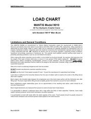
PAT DS-150 OPERATING CONTROLS<br />
See the LMI/A2B System Operator's Manual for complete control descriptions<br />
1. Display<br />
2. Load Moment Indicator Bar Graph<br />
3. Counterweight Toggle Switch<br />
4. Reeving Switch<br />
5. Anti-Two-Block Alarm Light<br />
6. Load Moment Prewarning Light<br />
7. Load Moment Alarm Light and<br />
Horn Off Button<br />
8. Load Indication Button<br />
9. INFO Button<br />
10. Angle Limit Button<br />
11. E Button<br />
12. Key Switch<br />
13. A2B Bypass Switch Position<br />
14. Normal Operation Position<br />
15. LMI Bypass Position<br />
16. Audible Alarm<br />
17. Operating Code Decade Switch<br />
<strong>10010</strong> REV: 2 10-97<br />
20
4. ENGINE OPERATION<br />
ALARM SYSTEMS<br />
The Mantis <strong>10010</strong> uses either the Caterpillar 3116 or<br />
the Cummins 6C-8.3l diesel engine with an integral<br />
hydraulic pump to provide power for all machine functions.<br />
This engine incorporates a number of alarm<br />
systems to protect the engine from abnormal operating<br />
conditions.<br />
The alarm systems provide a visual warning to signal<br />
the operator that an abnormal operating condition<br />
exists.<br />
Alarms are triggered by low oil pressure or high<br />
coolant temperature. Each alarm will continue until<br />
the cause of the alarm condition is corrected.<br />
See Section 2, Dash/Control Panels for a description<br />
of the <strong>10010</strong>’s engine alarms.<br />
WALK-AROUND INSPECTION<br />
For maximum service life of your engine, make a<br />
thorough inspection before starting the engine. Look<br />
for such items as oil or coolant leaks, loose fasteners,<br />
worn fan belts, and trash build-up. Remove trash<br />
build-up and have repairs made as needed.<br />
Perform required periodic maintenance before starting<br />
the engine. Make a walk-around inspection of the<br />
equipment. A few minutes spent making minor corrections<br />
can prevent major repairs later.<br />
NOTE:<br />
Accumulated grease and oil on an engine or platform<br />
is a fire hazard. Remove this debris with steam cleaning<br />
or high pressure water at least monthly or whenever<br />
any significant quantity of oil (or other fluid) is<br />
spilled on or near an engine and working area.<br />
Wipe fittings, caps, and plugs clean before servicing.<br />
Air Intake System<br />
• Observe the dash-mounted Air Filter Warning<br />
Light. Service the air cleaner when the light<br />
comes on.<br />
• Inspect the air intake system hoses, piping,<br />
elbows and gaskets for cracks or damage.<br />
Replace items as needed. Check for loose<br />
clamps and tighten if necessary.<br />
Water-Cooled Engine Cooling System<br />
• Inspect the cooling system for leaks and trash<br />
build-up. Clean any accumulation with compressed<br />
air or high-pressure water.<br />
• Inspect the water pump for leaks.<br />
NOTE:<br />
The water pump seal is lubricated by the engine<br />
coolant. A small amount of leakage as the engine<br />
cools down and parts contract is acceptable.<br />
• Inspect the system hoses and crankcase<br />
breather hose for cracks and loose clamps.<br />
• Inspect the fan and accessory drive belts for<br />
cracks, breaks, or other damage. Check for<br />
proper belt tension.<br />
21 <strong>10010</strong> REV: 2 10-97
Air-Cooled Engine Cooling System<br />
• Check all air flow paths for collection of debris<br />
that can block air flow. Clean any accumulation<br />
with compressed air or high-pressure water.<br />
CAUTION<br />
DO NOT SPRAY WATER ON A HOT ENGINE.<br />
• Inspect the fan and accessory drive belts for<br />
cracks, breaks, or other damage. Check for<br />
proper belt tension.<br />
Electrical System<br />
Wiring must be kept in good condition, properly routed<br />
and firmly attached. Routinely inspect wiring for<br />
wear or deterioration. Loose connectors or dangling<br />
wiring must be tightened or reattached. Do not<br />
bypass fuses.<br />
Tight connections and properly maintained cables will<br />
help prevent sparking that could cause a fire.<br />
• Inspect the engine-to-frame rail ground strap for<br />
good connection and condition.<br />
• Check the battery and battery cables for poor<br />
connections and corrosion.<br />
Fuel and Lube Systems<br />
• Make sure fuel lines are properly clamped and<br />
tight. Check for loose fittings or leaks.<br />
• Drain water from the water separator.<br />
• Check for lubrication leaks at areas such as the<br />
front and rear crankshaft seals, crankcase, oil<br />
filter, oil gallery plugs, sensors, and valve covers.<br />
NOTE:<br />
If you observe leaking fluid, find the source and correct<br />
the leak. If you suspect a fluid leak, check the<br />
fluid levels more frequently than the recommended<br />
service intervals until you either find a leak or prove<br />
to your satisfaction that there is no leak.<br />
Pre-Start Checks<br />
• All guards must be in place. Repair or replace<br />
all guards that are damaged or missing.<br />
• Measure the engine crankcase oil level. The<br />
correct oil level is between the High (H) and<br />
Low (L) marks on the dipstick. Unless stated<br />
otherwise in the Capacities & Specifications<br />
Chart, oil capacity from the low to high marks is<br />
1.9l (2.0 US quarts).<br />
NOTE:<br />
Make sure the crane is level when checking the<br />
engine oil level.<br />
• Check the oil level(s) on driven equipment.<br />
For water-cooled engines only:<br />
• Check the coolant level with the engine stopped<br />
and cold. Remove the filler cap slowly to relieve<br />
pressure gradually.<br />
• Maintain coolant level to within 13 mm (½ in) of<br />
the bottom of the fill pipe. Install the filler cap.<br />
NOTE:<br />
To prevent engine damage, never add coolant to an<br />
overheated engine. Allow the engine to cool first.<br />
• After starting, operate the engine at slow speed<br />
until it reaches operating temperature. Check<br />
the coolant level and add coolant if necessary.<br />
Check for any obvious cooling system leaks or<br />
loose connections. Inspect the water pump for<br />
evidence of leaks.<br />
• Disconnect any battery chargers that are not<br />
protected against the high current drain created<br />
when the electric starter engages.<br />
WARNING:<br />
Diesel engine exhaust contains combustion products<br />
which may be harmful to your health. Always start<br />
and operate the engine in a well ventilated area, and,<br />
if in an enclosed space, vent exhaust to the outside.<br />
Do not start the engine or move any of the controls if<br />
there is a “DO NOT OPERATE” or similar warning tag<br />
attached to the start switch or controls.<br />
The operator must be satisfied that no one will be<br />
endangered before starting the engine.<br />
<strong>10010</strong> REV: 2 10-97<br />
22
If the engine has not been run for several weeks, fuel<br />
may have drained and allowed air into the filter housing.<br />
Also, when fuel filters have been changed, some<br />
air space will be left in the housing.<br />
In these instances, prime the fuel system.<br />
NOTE:<br />
Do not engage the starter when the engine is turning.<br />
Do not start the engine under load.<br />
For starting below -18° C (0° F), use of optional cold<br />
weather starting aids is recommended. A coolant<br />
heater or extra battery capacity may be required.<br />
For temperature below -23° C (-10° F), consult your<br />
local diesel engine dealer.<br />
ELECTRIC STARTING<br />
NOTE:<br />
Starting ability will be improved at temperatures<br />
below 16° C (60° F) by the use of a starting aid<br />
and/or use of a jacket water (coolant) heater or other<br />
means to heat the cylinder block.<br />
Start the engine using the following procedure:<br />
1. Make sure that all hydraulic control levers are<br />
in their neutral positions.<br />
2. Turn the starter switch to the START position.<br />
Crank the engine. Release the switch as soon<br />
as the engine starts.<br />
NOTE:<br />
Do not crank the engine for more than 30 seconds.<br />
Allow the starter to cool for two minutes before cranking<br />
again.<br />
Turbocharger damage can result if the engine rpm is<br />
not kept low until the engine oil light or gauge verifies<br />
the oil pressure is sufficient.<br />
Consult the engine operating manual for complete<br />
details on proper operating speeds.<br />
If the engine does not start readily, especially at<br />
ambient temperatures below 16° C (60° F), use the<br />
Starting Aid pushbutton (if equipped) to inject starting<br />
fluid. While cranking the engine, depress and hold the<br />
Starting Aid switch for 3 seconds.<br />
At temperatures below 0° C (32° F), you may need to<br />
spray additional starting fluid directly into the air<br />
cleaner inlet.<br />
Additional injections of ether may also be required to<br />
achieve a low idle speed.<br />
WARNING:<br />
When using starting fluid, follow the manufacturer’s<br />
instructions carefully and use it sparingly. Failure to<br />
do so could result in explosion and/or fire and possible<br />
personal injury.<br />
NOTE:<br />
Excessive ether can cause piston and ring damage.<br />
Use ether for cold starting purposes only. Do not use<br />
excessive starting fluid during starting or after the<br />
engine is running.<br />
If the engine fails to start within 30 seconds, release<br />
the starter switch and wait two minutes to allow the<br />
starter motor to cool before using it again.<br />
3. Once the engine starts, allow it to run at low<br />
idle speed for three to five minutes, or until the<br />
engine temperature gauge indicator has begun<br />
to rise. Increase engine speed to high idle only<br />
after the engine is running smoothly at low idle.<br />
4. Allow the white smoke to clear up and proceed<br />
with normal operation. Do not apply load to the<br />
engine or increase engine speed until the oil<br />
pressure gauge indicates normal. Oil pressure<br />
should rise within 15 seconds after the engine<br />
starts.<br />
NOTE:<br />
If oil pressure does not rise within 15 seconds after<br />
the engine starts, stop the engine and follow necessary<br />
troubleshooting procedures before restarting.<br />
5. Operate the engine at low load and rpm until<br />
the engine temperature is within its normal<br />
range. Monitor all gauge readings during this<br />
warm-up period.<br />
23 <strong>10010</strong> REV: 2 10-97
STARTING WITH JUMPER CABLES<br />
WARNING:<br />
Batteries give off flammable fumes that can explode.<br />
Improper jumper cable connections can cause an<br />
explosion resulting in personal injury.<br />
Prevent sparks near the batteries. Sparks could<br />
cause vapors to explode. Do not allow jumper cable<br />
ends to contact each other or the engine.<br />
Do not smoke when observing the battery electrolyte<br />
levels.<br />
Always wear protective glasses when working with<br />
batteries.<br />
Electrolyte is an acid and can cause personal injury if<br />
it contacts skin or eyes.<br />
Engines installed without separate engine-to-frame<br />
rail ground straps can be damaged by electrical discharge.<br />
To prevent electrical discharge damage, check to<br />
make sure the engine’s electrical system has a separate<br />
engine-to-frame rail ground strap. For engines<br />
which have the alternator connected to an engine<br />
component, the ground strap must connect that component<br />
to the frame.<br />
Some engines have starter-to-frame ground straps,<br />
but many of these starters are not electrically grounded<br />
to the engine. They have electrical insulation systems.<br />
For this reason, the starter-to-frame ground<br />
strap may not be an acceptable engine ground.<br />
When boost starting, refer to the instructions that follow<br />
to properly start the engine.<br />
NOTE:<br />
When using an external electrical source to start your<br />
engine, turn the START switch OFF and turn off all<br />
electrical accessories before attaching cables.<br />
Your engine may be equipped with a 12 or 24 volt<br />
starting system. Use only the same voltage for boost<br />
starting. Use of a welder or higher voltage will damage<br />
the electrical system.<br />
When using jumper cables, always connect POSI-<br />
TIVE (+) cable to POSITIVE (+) battery terminal<br />
which is connected to starter solenoid and NEGA-<br />
TIVE (-) cable from external source to starter NEGA-<br />
TIVE (-) terminal. If not equipped with a starter NEG-<br />
ATIVE terminal, connect to the engine block.<br />
Do not reverse the battery cables. The alternator can<br />
be damaged.<br />
Attach the ground cable last and remove it first.<br />
1. Connect one end of the cable to the POSITIVE<br />
(+) terminal of the battery being started.<br />
Connect the other end to the POSITIVE (+)<br />
terminal of the power source.<br />
2. Connect one end of the other cable to the<br />
NEGATIVE (-) terminal of the power source.<br />
Connect the other end to the starter NEGA-<br />
TIVE (-) terminal or to the engine block. This<br />
prevents potential sparks from igniting combustible<br />
gases produced by some batteries.<br />
3. Begin cranking engine to start and achieve<br />
idle speed.<br />
4. After the engine starts, disconnect the cable<br />
from the starter NEGATIVE (-) terminal or<br />
engine block. Disconnect the other end from<br />
the NEGATIVE (-) terminal of the power<br />
source.<br />
5. Disconnect the cable from the POSITIVE (+)<br />
terminal of the battery on the engine being<br />
started. Disconnect the cable from the POSI-<br />
TIVE (+) terminal of the power source.<br />
<strong>10010</strong> REV: 2 10-97<br />
24
AFTER STARTING THE ENGINE<br />
As soon as the engine starts, release the starter<br />
switch and reduce rpm to low idle.<br />
NOTE:<br />
Keep engine speed low until the engine oil pressure<br />
registers on the gauge or the engine oil light goes<br />
out. If the gauge does not register or the light does<br />
not go out within fifteen seconds, stop the engine and<br />
investigate the cause before starting again. Failure to<br />
do so can cause engine damage.<br />
Allow a cold engine to warm up at LOW IDLE for at<br />
least five minutes. Do not apply load to the engine or<br />
increase engine rpm until the oil pressure gauge indicates<br />
normal.<br />
When idling the engine for warm up, observe the following<br />
recommendations:<br />
• In temperatures above 0° C (32° F), warm-up<br />
requires approximately 15 minutes.<br />
• In temperatures below 0° C (32° F), warm-up<br />
requires approximately 30 minutes or more.<br />
• In temperatures below -18° C (0° F), warm-up<br />
requires more than 30 minutes.<br />
Operate the engine at low load and rpm until the<br />
engine temperature reaches its normal operating<br />
range. Check all gauges during the warmup period.<br />
ENGINE STOPPING<br />
NOTE:<br />
Stopping the engine immediately after it has been<br />
working under load can result in overheating and<br />
accelerated wear of the engine components. Follow<br />
the stopping procedure outlined below to allow the<br />
engine to cool. Excessive temperatures in the turbocharger<br />
center housing could cause oil coking<br />
problems.<br />
Make sure that you understand the Engine Stopping<br />
procedure before operating the engine.<br />
Manual Stop Procedure<br />
1. Reduce engine speed to LOW IDLE.<br />
2. Remove load from engine by ceasing all<br />
hydraulic-powered operations.<br />
3. Increase engine speed to no more than half<br />
Full Load (rpm) speed for two minutes to cool<br />
the engine.<br />
4. Reduce engine speed to low idle for five minutes<br />
to cool the engine and prevent oil coking<br />
problems in the turbocharger center housing.<br />
5. Stop the engine by turning the Ignition Switch<br />
to Off.<br />
After the engine is started and the cold idle operation<br />
is completed, the engine can be operated at low<br />
speed and low power. The engine will reach normal<br />
operating temperature faster when operated at low<br />
speed and low power demand than when idled at no<br />
load.<br />
Maximum no-load speed for a warm engine is 2500<br />
rpm. Exceeding this limit may cause severe engine<br />
damage.<br />
Check all gauges and warning lights frequently during<br />
operation.<br />
25 <strong>10010</strong> REV: 2 10-97
AFTER STOPPING THE ENGINE<br />
1. After the engine cools, fill the fuel tank to prevent<br />
accumulation of moisture in the fuel.<br />
Water-cooled engines only:<br />
2. Maintain the cooling system to 13 mm (½<br />
inch) from bottom of the fill pipe.<br />
If you expect freezing temperatures, allow the engine<br />
jacket water cooling system to cool, then check the<br />
coolant for proper antifreeze protection. The system<br />
must be protected against freezing to the lowest<br />
expected outside temperature.<br />
Add a coolant mix of antifreeze and water. Refer to<br />
Appendix C of this manual for information about<br />
acceptable water and antifreeze concentrations.<br />
3. Check the engine crankcase oil level. The correct<br />
oil level is between the High (H) and Low<br />
(L) marks on the dipstick. Oil capacity from the<br />
low to high marks is 1.9l (2.0 US quarts).<br />
NOTE:<br />
Make sure the crane is level when checking the<br />
engine oil level.<br />
Always wait at least five minutes after shutting off the<br />
engine before checking the oil level to allow oil to<br />
drain back into the oil pan.<br />
4. Repair any leaks, perform minor adjustments,<br />
tighten loose bolts, etc.<br />
5. Observe the service meter reading. Perform<br />
periodic maintenance as indicated in<br />
Appendix B, Maintenance Chart.<br />
6. If the crane will be left unattended for an<br />
extended period of time (overnight or over a<br />
weekend, for example), turn off and lock the<br />
Battery Cutoff Switch (P.13). This will help prevent<br />
unauthorized use of the crane and/or<br />
accidental battery discharge.<br />
<strong>10010</strong> REV: 2 10-97<br />
26
5. MAIN WINCH CONTROLS<br />
Mounted at the left (inside) position of the right hand<br />
seat-mounted console is the control lever for the main<br />
winch raise/lower function. The main winch system<br />
consists of a manifold-mounted directional control<br />
valve that routes oil to the 2-speed winch motor causing<br />
the motor to rotate in the desired direction. The<br />
winch is equipped with an integral spring-applied,<br />
hydraulically-released disc brake that holds the load<br />
in position. Pressure applied to the brake valve<br />
unlocks the brake allowing the load to be lowered.<br />
WINCH OPERATION<br />
To raise a load, the control lever is pulled rearward; to<br />
lower a load, the control lever is pushed forward. As<br />
with all other functions, speed is directly proportional<br />
to engine speed and control displacement.<br />
A momentary pushbutton located on top of the winch<br />
control lever actuates the winch speed shifter valve.<br />
Pressing and holding the button selects high speed;<br />
releasing it selects low speed. The winch may be<br />
shifted from high to low or from low to high at any<br />
time during operation.<br />
If the crane is equipped with the optional “Thumb<br />
Thumper” indicators for winch rotation, this button<br />
vibrates whenever the auxiliary winch is rotating.<br />
When so equipped, auxiliary winch speed range is<br />
selected by the Main Winch Speed Range switch<br />
located on the lower panel of the right-side operator<br />
console.<br />
CAUTION<br />
DO NOT OPERATE THE WINCH IN HIGH SPEED IN<br />
THE LOWERING DIRECTION WITH A HEAVY LOAD<br />
DUE TO THE POSSIBILITY OF “OVER-<br />
RUNNING” THE MOTOR AND CAUSING DAMAGE<br />
TO THE MOTOR OR THE WINCH.<br />
Winch Warm-Up Procedure<br />
Performing a warm-up procedure is recommended at<br />
each start-up and is essential at ambient temperatures<br />
below 4° C (40° F).<br />
CAUTION<br />
FAILURE TO PROPERLY WARM UP THE WINCH,<br />
PARTICULARLY IN LOW TEMPERATURES, MAY<br />
RESULT IN TEMPORARY BRAKE SLIPPAGE.<br />
SUCH OPERATION WILL CREATE A HAZARDOUS<br />
SITUATION THAT MAY RESULT IN SERIOUS<br />
INJURY, DEATH AND/OR EQUIPMENT DAMAGE.<br />
To properly warm up the winch, run the <strong>10010</strong>’s<br />
diesel engine at its minimum recommended RPM<br />
with the hydraulic winch control lever in its neutral<br />
position. Once the engine has reached operating<br />
temperature, operate the winch with no load at low<br />
speeds, forward and reverse, several times to prime<br />
all lines with warm hydraulic oil and to circulate gear<br />
lubricant through the pla<strong>net</strong>ary gear sets.<br />
ANTI-TWO-BLOCK CONTROL<br />
The winch functions employ an LMI/A2B operator aid<br />
to prevent a “two-block” situation.<br />
When the load block or headache ball trips the antitwo-block<br />
switch, the switch actuates a solenoid valve<br />
which blocks control (pilot) pressure to the function.<br />
AUGER OPERATION<br />
If the <strong>10010</strong> is equipped with the optional auger package,<br />
the winch control lever also controls the direction<br />
and speed of the auger motor. The auger/winch<br />
selection is made by setting the dash-mounted<br />
Auger/Vibro ON/OFF toggle switch to the appropriate<br />
position.<br />
This switch energizes solenoid valves that divert pilot<br />
pressure to the directional control valve for the selected<br />
function. The momentary push button at the top of<br />
the control lever also controls the speed of the auger,<br />
as it does with the winch. See Winch Operation.<br />
27 <strong>10010</strong> REV: 2 10-97
<strong>10010</strong> REV: 2 10-97<br />
28
6. BOOM CONTROLS<br />
BOOM HOIST<br />
The joystick control lever mounted in the far right<br />
position of the right hand console controls the Boom<br />
UP/DOWN function. This function consists of a manifold-mounted<br />
directional control valve which is connected<br />
to a single double-acting cylinder. The cylinder<br />
is fitted with an integral counterbalance valve that<br />
holds the cylinder in the extended position until pressure<br />
is applied to the retract port, unlocking the valve<br />
and allowing the cylinder to lower the boom.<br />
To raise the boom, the control lever is pulled rearward;<br />
to lower the boom, the lever is pushed forward.<br />
As with all functions, the speed is directly proportional<br />
to engine speed and control displacement.<br />
The hydraulic system is not designed to raise the<br />
extended boom from an angle of less than 40<br />
degrees.<br />
BOOM TELESCOPE<br />
To the right of the swing brake pedal is the<br />
Telescope OUT/IN pedal. Pushing the pedal forward<br />
(toe down) extends the boom and pushing it backward<br />
(heel down) retracts the boom.<br />
The boom telescope system consists of two cylinders*<br />
mounted inside the boom that supply the force<br />
to extend and retract the boom.<br />
The boom is four-stage* and hydraulically operated.<br />
The second stage will extend fully before the third<br />
and fourth stages start to extend. As hydraulic pressure<br />
is applied to the sequence valve, the cylinder<br />
mounted in the second stage extends. At the end of<br />
its stroke, the valve will route the pressure to the<br />
cylinder mounted in the third stage. As the third stage<br />
extends, it will also extend the fourth (tip) stage<br />
through an arrangement of extend cables and<br />
sheaves mounted inside the boom. When retracting,<br />
the third and fourth stages will retract first, then the<br />
second stage will retract.<br />
The boom telescope cylinders are equipped with integral<br />
counterbalance valves that hold the boom in the<br />
extended position until pressure is applied to the<br />
retract port, unlocking the counterbalance valve and<br />
allowing the cylinder(s) to retract. As with all other<br />
functions, retract speed is directly proportional to<br />
engine speed and control displacement.<br />
* A two-stage, 40-foot boom with a single telescope<br />
cylinder is optional.<br />
ANTI-TWO-BLOCK (A2B) CONTROL<br />
The Boom Down and Boom Telescope Out functions<br />
employ the LMI/A2B operator aid to prevent a “twoblock”<br />
situation.<br />
When the load block or headache ball trips the antitwo-block<br />
switch, the switch actuates a solenoid valve<br />
which blocks control (pilot) pressure to the function.<br />
29 <strong>10010</strong> REV: 2 10-97
<strong>10010</strong> REV: 2 10-97<br />
30
7. SWING CONTROLS<br />
SWING CONTROL<br />
In the far left position of the left-hand console is the<br />
swing control. The swing system consists of a directional<br />
control valve, hydraulic motor, a springapplied/hydraulically-released<br />
park brake with an integral<br />
spring-released hydraulically-applied service<br />
brake and a gear reducer mounted to the upper<br />
structure of the crane.<br />
The console-mounted control lever supplies pilot<br />
pressure to the directional control valve which routes<br />
pump flow to the swing motor, which through the<br />
brake, causes the reducer to turn the shaft-mounted<br />
pinion gear, meshed with the slew ring, and the upper<br />
structure.<br />
To swing left, the control lever is pulled rearward; to<br />
swing right, the lever is pushed forward. As with all<br />
functions of the crane, speed is directly proportional<br />
to engine speed and control displacement.<br />
SWING PARK BRAKE<br />
The park brake is controlled by the Swing Park<br />
Brake ON/OFF switch. The park brake is used to<br />
hold the upper structure in position for extended periods<br />
of time.<br />
CAUTION<br />
NEVER USE THE PARK BRAKE TO STOP THE<br />
SWING MOTION OF THE UPPER STRUCTURE<br />
UNDER ANY CIRCUMSTANCES<br />
SWING SERVICE BRAKE<br />
The service brake is controlled by the floor-mounted<br />
foot pedal (far left) and is used to slow and stop the<br />
swing motion of the crane upper structure.<br />
DANGER!<br />
NEVER REST YOUR FOOT ON THE SWING<br />
BRAKE PEDAL DURING SWING OPERATION;<br />
EVEN SLIGHT PRESSURE WILL CAUSE EXCES-<br />
SIVE WEAR ON THE SWING BRAKE MECHANISM<br />
At the top of the swing control lever is the horn button.<br />
When depressed, the horn will sound, alerting all<br />
personnel that swing or some other function is about<br />
to be put into motion. It is good practice to sound the<br />
horn before putting any functions into motion.<br />
31 <strong>10010</strong> REV: 2 10-97
<strong>10010</strong> REV: 2 10-97<br />
32
8. TRAVEL CONTROLS;<br />
TRACKS EXTEND/RETRACT CONTROLS<br />
TRACKS FORWARD/REVERSE TRACKS EXTEND/RETRACT<br />
The travel function is controlled by two floor-mounted<br />
foot pedals which actuate control valves to route pilot<br />
pressure to the manifold-mounted directional control<br />
valves. In the forward direction (boom over the idler<br />
end) the left pedal controls the left track and the right<br />
pedal controls the right track.<br />
Pushing the pedal(s) toe-down moves the crane forward.<br />
For reverse travel, pushing the pedals heeldown<br />
moves the crane backward. The speed of travel,<br />
as with all other functions, is directly proportional<br />
to engine speed and control displacement.<br />
To skid-steer, one of the pedals is pushed farther<br />
down than the other, causing one track to pull ahead<br />
of the other.<br />
Counter-rotation (turning the crane on its own axis) is<br />
achieved by moving one pedal toe-down and the<br />
other heel-down, depending on the desired direction.<br />
The track drive motors are equipped with springapplied,<br />
pressure-released park brakes controlled by<br />
the dash-mounted Park Brake ON/OFF toggle<br />
switch. The park brake switch must be set to off<br />
before travel can be initiated. Also connected to the<br />
park brake switch is the motion alarm, which will<br />
sound any time the park brake switch is turned off.<br />
This alarm will alert all personnel that travel can<br />
occur at any time.<br />
The <strong>10010</strong>’s track extend/retract function powers the<br />
crawler frames in or out. The track extend/retract<br />
function is actuated by the dash-mounted Tracks<br />
EXTEND/RETRACT toggle switch. The carbodymounted<br />
extend/retract cylinders are fitted with integral<br />
cross-flow check valves to prevent the cylinders<br />
from drifting in or out unless pressure is applied.<br />
DANGER!<br />
NEVER OPERATE THE CRANE WITHOUT FIRST<br />
FULLY EXTENDING THE CRAWLER FRAMES*.<br />
ATTEMPTING TO LIFT LOADS WITH THE<br />
CRAWLER FRAMES RETRACTED WOULD VERY<br />
LIKELY CAUSE OVERTURNING, WHICH WILL<br />
RESULT IN SERIOUS INJURY, DEATH AND/OR<br />
EQUIPMENT DAMAGE*.<br />
*UNLESS OPERATIONS ARE WITHIN<br />
PARAMETERS SPECIFICALLY ALLOWED BY THE<br />
“TRACKS RETRACTED LOAD CHART” FOR THIS<br />
MODEL.<br />
The track drive motors are two-speed and are shifted<br />
by pilot pressure through a solenoid valve controlled<br />
by a dash-mounted toggle switch, marked Travel<br />
Speed HIGH/LOW.<br />
CAUTION<br />
DO NOT SHIFT BETWEEN TRAVEL SPEEDS<br />
WHILE THE CRANE IS IN MOTION.<br />
Maximum tractive effort is realized with the motors in<br />
“low” speed, the engine at top speed and maximum<br />
pedal displacement.<br />
33 <strong>10010</strong> REV: 3 04-00
<strong>10010</strong> REV: 2 10-97<br />
34
9. AUXILIARY WINCH CONTROL<br />
AUXILIARY WINCH (OPTIONAL)<br />
If the crane is equipped with the optional two-speed<br />
auxiliary winch, winch operation is controlled by the<br />
Auxiliary Winch control lever on the right-side operator’s<br />
console. Side-to-side movement of the fourway<br />
joystick controls the auxiliary winch. Moving it to<br />
the right lowers the hook block and moving it to the<br />
left raises the hook block.<br />
The dash-mounted Winch Speed toggle switch<br />
selects the high or low range of auxiliary winch rotation<br />
speed. As with other crane functions, speed within<br />
ranges is directly proportional to engine speed and<br />
control displacement.<br />
CAUTION<br />
NEVER LEAVE THE CRANE CAB WITH THE<br />
ENGINE RUNNING.<br />
The auxiliary winch also employs an LMI/A2B operator<br />
aid, in the “raise” direction, to aid the operator in<br />
preventing a two blocking situation when the switchmounted<br />
weight at the boom, stand off, extension or<br />
jib tip is raised by the hook block or headache ball.<br />
35 <strong>10010</strong> REV: 2 10-97
CAUTION<br />
Controlled<br />
Freefall (Option)<br />
The <strong>10010</strong>’s auxiliary winch may be equipped with a<br />
controlled freefall option. This option is used with the<br />
optional vibrohammer to provide efficient pile driving.<br />
When the trigger is squeezed to the limit, the relief<br />
valve closes entirely. All oil must then pass through<br />
the metering pump, which gives a uniform maximum<br />
speed.<br />
The controlled freefall option uses a joystick-mounted<br />
trigger, an electrically-operated, normally-open, proportional<br />
relief valve, and a special winch with integral<br />
multi-disc brake.<br />
Under normal operation (no freefall), oil flows freely<br />
from the winch’s freefall brake release port through<br />
the relief valve; the brake is held tight by spring pressure.<br />
When the operator squeezes the trigger, the relief<br />
valve closes proportionately, allowing less oil flow<br />
from the winch’s brake release port. The resulting<br />
increase in pressure at the brake port causes the<br />
brake to release slightly. At the same time, a metering<br />
pump driven by the winch pumps a small quantity of<br />
oil out of the control circuit to compensate for the<br />
change from static to dynamic friction in the brake.<br />
As the<br />
freefall<br />
trigger<br />
is<br />
MAXIMUM FREEFALL LOAD AND LINE SPEED VS. DRUM FILL<br />
(Multiply the load by the number of parts of line used<br />
to determine maximum freefall load capacity)<br />
LAYER LINE PULL (LBS) LINE SPEED (FT/MIN)<br />
1 6030 158<br />
2 5400 177<br />
3 4880 195<br />
4 4460 214<br />
5 4100 232<br />
6 3800 251<br />
squeezed further, the flow through the relief valve is<br />
further restricted, causing a higher pressure at the<br />
brake release port and a higher freefall speed.<br />
<strong>10010</strong> REV: 2 10-97<br />
36
10. TOOL/AUGER/VIBROHAMMER OPERATION<br />
THE FREEFALL BRAKE CAN STOP THE MAXIMUM<br />
LOAD THAT THE WINCH CAN LIFT. TO AVOID<br />
OVERHEATING, HOWEVER, THE MAXIMUM<br />
FREEFALL LOAD SHOULD BE LIMITED TO 30% OF<br />
THE WINCH’S RATED CAPACITY.<br />
EFFECTIVE WINCH CAPACITY VARIES GREATLY<br />
WITH DRUM FILL AND REEVING. IF YOU HAVE<br />
NOT CALCULATED EFFECTIVE CAPACITY BASED<br />
ON KNOWN REEVING AND DRUM FILL INFORMA-<br />
TION, LIMIT THE FREEFALL LOAD TO 3,800 LBS.<br />
TIMES THE NUMBER OF PARTS OF LINE USED.<br />
ALWAYS USE THE MAIN CONTROL VALVE FOR<br />
LOWERING HEAVY LOADS WITH THE AUXILIARY<br />
WINCH.<br />
If the drum fill is known, you can calculate the<br />
maximum freefall capacity by using the table<br />
below. Multiply the maximum line pull by the<br />
number of parts of line used.<br />
37 <strong>10010</strong> REV: 2 10-97
Tool Circuit Operation<br />
The MANTIS <strong>10010</strong> may be equipped with the<br />
optional tool circuit for operating hydraulic impact<br />
wrenches, tampers, etc. The tool circuit is designed<br />
to deliver either 5 or 10 GPM at 2100 PSI (18.9 or<br />
37.8 l/min @ 147 bar), to the reel-mounted hose at<br />
the left side of the crane, behind the operator’s cab.<br />
Hoses on the reel are fitted with quick-disconnect<br />
couplings to attach the desired tool. The tool circuit is<br />
activated by the dash-mounted Tool HIGH/<br />
OFF/LOW toggle switch.<br />
Digging With the Auger<br />
NOTE:<br />
All auger controls described below are located in the<br />
right-hand operator’s console.<br />
The optional auger circuit utilizes the winch control<br />
lever to control the direction and speed of auger rotation.<br />
The operator selects auger operation by setting<br />
the Auger/ Winch toggle switch to the AUGER position.<br />
Use the following steps to prepare the auger for<br />
digging:<br />
1. Set the Auger/Winch switch to the AUGER<br />
position and remove the safety pin from the<br />
auger storage latch.<br />
2 Slowly push the Winch/Auger Control lever<br />
forward to be sure the wind-up cable is supporting<br />
the auger.<br />
Lower the auger into the earth by pushing the Boom<br />
UP/DOWN lever forward; raise the auger by pulling<br />
the lever backward. The operator must determine<br />
proper digging and lowering rates depending on soil<br />
conditions.<br />
High or low range of auger rotation speed is selected<br />
with the Auger Speed HIGH/LOW Switch.<br />
Stowing the Auger<br />
When digging is complete, return the auger to the<br />
stowed position in the storage latch using the following<br />
steps:<br />
1. Attach the wind-up cable to the auger shaft.<br />
Move the Auger Latch OPEN/CLOSE switch<br />
to OPEN.<br />
2. Push the Winch/Auger Control lever forward<br />
to draw the auger into the latch.<br />
3. After the auger shaft contacts the torque limiting<br />
valve and the motor stops rotating, set the<br />
Auger Latch OPEN/CLOSE switch to<br />
CLOSE, install the safety pin, and pull the<br />
control lever rearward, lowering the auger<br />
shaft to the latch plunger.<br />
When not in use, the auger may be left in the digging<br />
position with the Auger/Winch switch set to WINCH,<br />
if desired, to prevent spending excessive time in storing<br />
and rigging the auger.<br />
3. Open the latch by setting the Auger Latch<br />
OPEN/CLOSE toggle switch to the OPEN<br />
position.<br />
4. With the latch open, slowly pull the control<br />
lever rearward to lower the auger out of the<br />
latch until the wind-up cable swings clear.<br />
With the auger in digging position, push the winch<br />
control lever forward to dig and pull it rearward for<br />
reverse. As with all other functions, auger rotation<br />
speed is directly proportional to engine speed and<br />
control lever displacement.<br />
<strong>10010</strong> REV: 2 10-97<br />
38
APPENDIX A: BOOM LOAD CHARTS<br />
CAPACITY LIMITS AND<br />
GENERAL CONDITIONS<br />
The MANTIS <strong>10010</strong> Crane as manufactured by<br />
SpanDeck, Inc. meets the requirements of ANSI<br />
B30.5c (1992) when specifically equipped. Structure<br />
and stability have been tested in accordance with SAE<br />
J1063 and SAE J765, respectively. Lifting capacities<br />
as determined by boom length, angle, or lifting radius<br />
apply only to machines as originally equipped by the<br />
manufacturer and in a properly maintained condition.<br />
Capacities given are maximum covered by the manufacturer’s<br />
warranty and are based on a freely suspended<br />
load with no allowance for factors such as out-oflevel<br />
operation, supporting surface conditions, hazardous<br />
surroundings, experience of personnel, etc.<br />
The operator shall establish practical working loads<br />
based on prevailing operating conditions such as, but<br />
not limited to, those listed above.<br />
When making lifts where capacities may be within a<br />
zone limited by structural strength, the operator shall<br />
determine that the weight of the load is known within ±<br />
10% before making the lift.<br />
DO NOT lift a load without consulting the Load Chart.<br />
Deductions from rated capacities must be made for the<br />
weight of the hook block, overhaul ball, slings, spreader<br />
bar, or other suspended equipment.<br />
DANGER!<br />
SIDE PULL ON THE BOOM IS EXTREMELY<br />
DANGEROUS AND MUST BE AVOIDED.<br />
DO NOT EXCEED THE MANUFACTURER’S SPECI-<br />
FIED MAXIMUM REEVING.<br />
Load radius is defined as the horizontal distance from<br />
the axis of rotation to the center of the lifting device<br />
after load is applied.<br />
Boom angle/boom length relationships given in the<br />
load charts are an approximation of the resulting load<br />
radius. The radius should be accurately measured.<br />
Boom height dimensions are measured from ground to<br />
center of lower boom head sheave.<br />
It is permissible to attempt to telescope the boom with<br />
a load within the limits of rated capacities. However,<br />
boom angle, system hydraulic pressure, and/or boom<br />
lubrication may affect operation.<br />
CAUTION<br />
THE LOAD MOMENT INDICATOR SYSTEM USED<br />
ON THE <strong>10010</strong> IS AN OPERATIONAL AID THAT<br />
WARNS THE CRANE OPERATOR OF APPROACH-<br />
ING OVERLOAD CONDITIONS AND ALSO WARNS<br />
OF OVERHOIST CONDITIONS WHICH COULD<br />
CAUSE DAMAGE TO EQUIPMENT AND INJURY TO<br />
PERSONNEL.<br />
THE DEVICE IS NOT, AND SHALL NOT BE, A SUB-<br />
STITUTE FOR GOOD OPERATOR JUDGMENT,<br />
EXPERIENCE, AND THE USE OF ACCEPTED<br />
CRANE OPERATING PROCEDURES.<br />
THE RESPONSIBILITY FOR THE SAFE OPERATION<br />
OF THE CRANE SHALL REMAIN WITH THE CRANE<br />
OPERATOR, WHO SHALL ENSURE THAT HE<br />
UNDERSTANDS AND OBSERVES ALL SUPPLIED<br />
WARNINGS AND INSTRUCTIONS.<br />
PRIOR TO OPERATING THE CRANE, THE OPERA-<br />
TOR MUST CAREFULLY AND THOROUGHLY READ<br />
AND UNDERSTAND THE INFORMATION IN THIS<br />
MANUAL TO ENSURE THAT HE KNOWS THE<br />
OPERATION AND LIMITATIONS OF THE LMI/A2B<br />
SYSTEM AND CRANE.<br />
PROPER FUNCTIONING IS DEPENDENT UPON<br />
PROPER DAILY INSPECTIONS AND UPON OBSER-<br />
VATION OF THE OPERATING INSTRUCTIONS SET<br />
FORTH IN THE LMI/A2B MANUAL.<br />
Boom angle is the included angle between the longitudinal<br />
axis of the boom base section and the horizontal<br />
axis, after lifting the load. The boom angle before lifting<br />
should be somewhat greater than desired to account<br />
for boom deflection.<br />
39 <strong>10010</strong> REV: 2 10-97
<strong>10010</strong> REV: 2 10-97<br />
40
APPENDIX B: MAINTENANCE CHART<br />
COMMENTS<br />
ENGINE<br />
Crankcase<br />
Check oil level<br />
Check for leaks<br />
Change oil and filter<br />
Check valve lash<br />
Clean crankcase breather<br />
•<br />
•<br />
•<br />
•<br />
•<br />
check at dipstick<br />
repair, see Capacities & Specifications Chart<br />
see Manufacturer Maintenance manual<br />
Cooling System<br />
Check coolant level<br />
Check for leaks<br />
•<br />
•<br />
check “cold”, add as required<br />
see Capacities & Specifications Chart<br />
Fuel System<br />
Check fuel level<br />
Drain fuel/water separator<br />
Drain dirty fuel<br />
Replace fuel filter<br />
Drain water/sediment<br />
from tank<br />
Clean fuel inlet & screen<br />
•<br />
•<br />
•<br />
•<br />
•<br />
•<br />
fill at end of each day<br />
drain until clean fuel evident<br />
see Manufacturer Maintenance manual<br />
Air Supply<br />
Clean air pre-cleaner<br />
bleeder valve<br />
•<br />
HYDRAULIC SYSTEM<br />
Check hydraulic oil level<br />
Check filter condition indicator<br />
Check for leaks<br />
Clean hydraulic tank<br />
filler/breather cap<br />
Drain hydraulic tank<br />
Change hydraulic filters<br />
new or rebuilt machines<br />
after 1st filter change<br />
•<br />
• •<br />
•<br />
•<br />
•<br />
•<br />
•<br />
check for “Desired Level” at tank sight gauge, all<br />
cylinders fully retracted and oil at operating<br />
temperature. Add as required, see Capacities &<br />
Specifications Chart<br />
change as required, or at least every 1,000 hrs.<br />
“walk around” inspection of entire machine,<br />
repair as required<br />
clean with solvent<br />
drain, clean, and refill, see Capacities &<br />
Specifications Chart<br />
after initial filter change at 100 hours<br />
TRAVEL/TRACKS<br />
Check track drive reducers<br />
•<br />
check level at “level” plug with “fill” and “drain”<br />
plugs in vertical alignment. Add as required, see<br />
Capacities & Specifications Chart<br />
41 <strong>10010</strong> REV: 2 10-97
COMMENTS<br />
TRAVEL/TRACKS (continued)<br />
Check/Adjust track tension<br />
Clean/Grease track extend beams<br />
Inspect undercarriage<br />
•<br />
•<br />
•<br />
measure slack between top rollers;<br />
30mm / 1.187 inches.<br />
remove all debris and coat top, side, and bottom<br />
surfaces<br />
check all components for wear/damage, repair or<br />
replace as required.<br />
WINCH(ES)<br />
Check oil level<br />
Check for leaks<br />
Change oil (1st time)<br />
Change oil (after 1st change)<br />
Disassemble & inspect freefall assy.<br />
•<br />
•<br />
•<br />
add as required<br />
(G2H30G freefall winches: not required)<br />
repair as required<br />
see Capacities & Specifications Chart<br />
• see Capacities & Specifications Chart<br />
• per Gearmatic G2H30G maintenance manual<br />
BOOM<br />
Grease boom sheave<br />
Grease boom bearing pads<br />
Grease boom pins<br />
Change swing drive reducer oil<br />
Change swing drive reducer oil<br />
Grease slew ring race<br />
Grease slew ring teeth<br />
Check wire rope<br />
•<br />
•<br />
•<br />
•<br />
•<br />
•<br />
•<br />
inspect for damage, replace as required,<br />
see Capacities & Specifications Chart<br />
inspect for damage, replace as required,<br />
see Capacities & Specifications Chart<br />
inspect for damage, replace as required,<br />
see Capacities & Specifications Chart<br />
drain at operating temperature (initial oil<br />
change) see Capacities & Specifications<br />
Chart<br />
• after initial change at 50 hours<br />
grease while rotating until grease is visible at<br />
seal, see Capacities & Specifications Chart<br />
coat with open gear lube<br />
check for damage, replace as required<br />
AUXILIARY GENERATOR (OPTION)<br />
Check oil level<br />
Change oil<br />
Replace air cleaner element<br />
Change fuel filter<br />
Clean fins<br />
Change oil and filter<br />
•<br />
•<br />
•<br />
•<br />
•<br />
•<br />
initial oil change<br />
clean cooling air flow path<br />
after initial oil change<br />
CAB INSTRUMENTATION<br />
Check for proper operation<br />
•<br />
repair or replace as required<br />
<strong>10010</strong> REV: 2 10-97<br />
42
APPENDIX C: CAPACITIES & SPECIFICATIONS<br />
EQUIPMENT MATERIAL CAPACITY/QUANTITY COMMENTS<br />
Engine Lube Oil API CF-4/SG 15 l (16 US quarts) Cat 3116, Cummins B5.9<br />
CF-4/SF 23.8 l (25.2 US quarts) Cummins C8.3<br />
CE/SG 36.7-29.1 l (9.7-7.7 US gal) Cummins M11 (high-low)<br />
SAE 15w40<br />
(capacities<br />
with filter change)<br />
Engine Cooling System water/antifreeze mix 24.2 l (26.7 US quarts) Cat 3116<br />
18.9 liters (20 US quarts) Cummins B5.9<br />
26.5 l (28 US quarts) Cummins C8.3<br />
45.4 l (12 US gal) Cummins M11<br />
use mix for protection at<br />
ambient temperatures<br />
Hydraulic Tank Shell Tellus T-32 1200 liters (350 US gallons) 8010/<strong>10010</strong>/12010<br />
1000 liters (264 US gallons) 6610<br />
Diesel Fuel Tank No.1 or No.2 Diesel 420 liters (110 US gallons) 8010/<strong>10010</strong>/12010<br />
302 liters (80 US gallons) 6610<br />
Swing Drive Reducer EP 90 fill to 4.5 cm (1.75 inches)<br />
below outside of housing<br />
fill/check plug, minimum<br />
Winch (Main & Aux.) Texaco Meropa 150 fill to bottom of level plug 8010 main, aux: CH175<br />
(-20°F to 80°F) CH175: 4.3 l (4.5 US qts) 100/12010 main: CH185<br />
Mobil SHC 630 synthetic CH185: 17.0 l (18 US qts) 100/12010 aux: CH175<br />
(-40°F to -20°F) PD12C: 1.4 l (1.5 US qts) 6610 main: CH175<br />
6610 aux: PD12C<br />
Winch (Aux. w/Freefall) N/A*** N/A G2H30G<br />
Track Drive Reducers EP 90 6 liters (6.4 US quarts) 100/12010 (Linde)<br />
6.8 liters (7.5 US quarts) 6610/8010 (KYB-5000)<br />
Track Rollers EP 90 0.34kg (.75 US lbs.) Berco KL18C<br />
0.23 l (.24 US quart) InterTractor<br />
see * below for filling<br />
Track Idlers EP 90 0.45 kg (.99 US lbs.)<br />
Boom Sheaves Shell Alvania until “new”’ grease is visible Fittings in end of pins<br />
EP-2 or Equis<br />
(12 places)<br />
Boom Cylinder Pins EP-2 until “new”’ grease is visible 4 places<br />
Boom Foot Pin EP-2 until “new”’ grease is visible 2 places<br />
Boom Bearing Pads EP-2 as required spread grease on<br />
bearing areas of boom<br />
Slew Ring Race Shell Alvania as required grease while rotating until<br />
EP-2 or equivalent<br />
“new” grease is visible at seal<br />
Slew Ring Teeth Texaco “Crater” 2X or 5X coat teeth at each greasing<br />
Batteries Distilled water keep level at split rings<br />
under caps<br />
Auger Motor GL-5 EP SAE 80/90 4.7 liters (5 US quarts) Eskridge Model 74<br />
see ** below for filling<br />
Auxiliary Generator (Optional)<br />
• Lube oil same as main engine 0.8 liters<br />
• Fuel tank see Diesel Fuel Tank connected to tank of crane<br />
Track tension Shell Alvania as required see maintenance chart<br />
EP-2 or equivalent<br />
for adjustment procedure<br />
* Test level with fill plug removed; maximum level: no overflow from fill hole @ 40° above horizontal axis;<br />
minimum level: overflow from fill hole @ 10° above horizontal axis.<br />
** Measure to middle of primary pla<strong>net</strong> gears when the auger is in vertical position. Tilt back slightly when<br />
filling through oil fill hole to achieve proper capacity.<br />
*** The auxiliary winch with freefall option is lubricated with hydraulic fluid; no routine changes are required.<br />
43 <strong>10010</strong> REV: 2 10-97
<strong>10010</strong> REV: 2 10-97<br />
44
APPENDIX D: FILTER SPECIFICATIONS<br />
45 <strong>10010</strong> REV: 2 10-97
<strong>10010</strong> REV: 2 10-97<br />
46
APPENDIX E: COLD WEATHER OPERATION<br />
Diesel engines can operate effectively in cold weather.<br />
Engine operation in cold weather, however, is<br />
dependent on the type of fuel used and how well the<br />
fuel moves through the fuel-related components. The<br />
purpose of this appendix is to explain some of the<br />
problems and steps that can be taken to minimize<br />
fuel problems during cold weather operation when the<br />
engine area is colder than 40° F (5° C).<br />
Fuel Selection<br />
During cold weather operation, you may need to use<br />
No. 2 diesel fuel since quantities of No. 1 diesel fuel<br />
are limited and generally are only available during the<br />
winter months and in the colder climates.<br />
There are two major differences between No. 1 and<br />
No. 2 diesel. No. 1 diesel has a lower cloud point and<br />
a lower pour point.<br />
The cloud point is the temperature at which a cloud<br />
or haze of wax crystals begins to form in the fuel and<br />
cause fuel filters to plug. The pour point is the temperature<br />
at which diesel fuel begins to thicken and<br />
becomes more resistant to flow through fuel pumps<br />
and lines.<br />
Be aware of these fuel values when purchasing your<br />
diesel fuel and anticipate the average outside (ambient)<br />
temperature for the area where your Mantis<br />
crane will be operating. Engines fueled in one climate<br />
may not operate satisfactorily if moved to another<br />
because of problems that result from cold weather.<br />
NOTE:<br />
The average No. 1 diesel fuel has a lower heat content<br />
(kJ or BTU) rating per unit volume of fuel than<br />
the average No. 2 diesel fuel. When using No. 1<br />
diesel fuel, you may notice a drop in power and fuel<br />
efficiency, but you should not experience any other<br />
operating effects.<br />
Fuel Heaters<br />
Fuel heaters prevent plugging of the fuel filters due to<br />
waxing in cold weather. Mantis cranes intended for<br />
use in cold climates are equipped with suitable fuel<br />
heaters and control circuitry. See the Maintenance<br />
Manual for your crane for details.<br />
Make sure that the fuel heater is deactivated in warm<br />
weather. A loss of engine power can occur if the fuel<br />
supply temperature exceeds 85° F (30° C).<br />
Fuel Filters<br />
Mantis diesel-powered cranes are equipped with a<br />
water separator between the fuel tank and the<br />
engine-mounted fuel filter. The micron rating and<br />
location of the water separator are chosen for proper<br />
operation in cold weather. The water separator and<br />
its fuel supply line are the components most commonly<br />
affected by cold fuel.<br />
Engine Compartment Temperature<br />
Maintaining as high a temperature as possible in the<br />
engine compartment can be very helpful in avoiding<br />
cold weather problems in your Mantis crane.<br />
Always keep all engine covers and access panels<br />
closed in cold weather to retain as much engine heat<br />
as possible.<br />
Depending on the options you specified, your crane<br />
may have a radiator shutter, winter front, and/or thermostatically<br />
controlled (clutch-type) fan to minimize<br />
warm-up times.<br />
At coolant temperatures below 160° F (71° C) the<br />
clutch fan should be off; at temperatures above 205°<br />
F (96° C) the fan should operate. If your engine will<br />
not maintain proper operating temperature, check the<br />
fan for proper operation.<br />
Before troubleshooting for low power or poor performance<br />
in winter months, check the type of fuel you<br />
are using.<br />
The use of starting aids, engine oil pan heaters,<br />
coolant heaters, fuel heaters, and fuel line insulation<br />
also provide some means of minimizing starting and<br />
fuel problems in cold weather when No. 2 fuel is<br />
used.<br />
47 <strong>10010</strong> REV: 2 10-97
<strong>10010</strong> REV: 2 10-97<br />
48
APPENDIX F: REEVING DIAGRAM<br />
Operating the Vibrohammer<br />
CENTER SHEAVE<br />
FOR JIB<br />
TO DEAD END<br />
ANCHOR<br />
AUXILIARY<br />
WINCH<br />
MAIN WINCH<br />
BOOM HEAD,<br />
TOP SHEAVES<br />
BOOM HEAD,<br />
BOTTOM SHEAVES<br />
HOOK BLOCK<br />
The optional vibrohammer is used to drive and extract pilings. Depending on operator preference and/or site<br />
conditions, the vibrohammer may be attached to either the main or auxiliary winch; the other winch supports the<br />
piling to be driven<br />
DANGER!<br />
DO NOT EXCEED THE MANUFACTURER’S<br />
SPECIFIED MAXIMUM REEVING OF<br />
10 PARTS OF LINE<br />
49 <strong>10010</strong> REV: 2 10-97
(or extracted).<br />
Use the following steps to drive (or extract) pilings<br />
with the vibrohammer:<br />
1. Attach either the main or auxiliary winch line<br />
and the hydraulic supply and return lines to the<br />
vibrohammer. Attach the other winch line to the<br />
piling to be driven (or extracted).<br />
2. Raise the vibrohammer, making sure that the<br />
hydraulic lines are not pinched or stressed.<br />
3. Pull the piling into the clamp jaws. Set the<br />
Clamp OPEN/CLOSE toggle switch to the<br />
close position to secure the vibrohammer to<br />
the piling. When the clamp pressure reaches<br />
5000 psi, the Clamp Pressure light will come<br />
on.<br />
4. Place the piling in position, then turn the<br />
Vibrohammer ON/OFF switch on to activate<br />
the vibrohammer. Use the main and auxiliary<br />
winch controls as required to maintain proper<br />
driving (or extracting) action.<br />
NOTE:<br />
THE VIBROHAMMER WILL NOT OPERATE<br />
UNLESS THE CLAMP PRESSURE LIGHT IS LIT.<br />
5. When the piling is driven to the desired depth<br />
(or extracted fully), turn the Vibrohammer<br />
ON/OFF switch to off and the Clamp<br />
OPEN/CLOSE switch to open. Disengage the<br />
vibrohammer from the piling.<br />
<strong>10010</strong> REV: 2 10-97<br />
50
APPENDIX G: PREPARATION FOR SHIPPING<br />
NOTE:<br />
10-PART REEVING IS REQUIRED FOR FULL<br />
CAPACITY LIFTING<br />
DANGER!<br />
Removable Component Weights & Dimensions<br />
Weights are given in KIPs (pounds)<br />
6610 8010 <strong>10010</strong>/12010<br />
Crawler frame 17.6 (17,600) 17.6 (17,600) 17.6 (17,600)<br />
Counterweight(s) 10.0 (10,000) 15.0 (15,000)* 30.0 (30,000)<br />
[2 @15.0]<br />
Lattice jib 0.7 (700) 0.7 (700) 0.7 (700)<br />
Lattice extension 1.1 (1,100) 1.1 (1,100) 1.1 (1,100)<br />
Main boom 13.7 (13,700) 19.7 (19,700) 19.7 (19,700)<br />
Boom hoist cylinder 1.6 (1,600) 1.6 (1,600) 3.0 (3,000)<br />
Foot pin centerline 5.9m (19.4ft) 5.4m (17.8ft) 5.4m (17.8ft)<br />
to boom CG (center of gravity)<br />
*Heavy lift option adds 2nd 15.0 KIP (15,000 lb) counterweight<br />
51 <strong>10010</strong> REV: 2 10-97
Due to the weight and overall width of the Mantis<br />
6610/8010 and <strong>10010</strong>/12010 cranes, it may be necessary<br />
to remove certain components from the<br />
machine for transport in your area. The procedures in<br />
the following appendices will guide you through disassembly<br />
and reassembly of your crane if the need<br />
arises.<br />
WHEN INSTALLING OR REMOVING ANY COMPO-<br />
NENT OF A MANTIS CRANE, USE THE SAME<br />
SAFETY PROCEDURES THAT YOU USE WHEN<br />
MAKING ANY OTHER LIFT WITH THE CRANE.<br />
<strong>10010</strong> REV: 2 10-97<br />
52
APPENDIX H:<br />
COUNTERWEIGHT REMOVAL/INSTALLATION<br />
The counterweight of the <strong>10010</strong> is installed or<br />
removed by using the crane's Boom Telescope Out/In<br />
Control (see Page 9) with special counterweight handling<br />
rigging installed.<br />
DANGER!<br />
WHEN INSTALLING OR REMOVING THE COUN-<br />
TERWEIGHT, USE THE SAME SAFETY PROCE-<br />
DURES THAT YOU USE WHEN MAKING ANY<br />
OTHER LIFT WITH THE <strong>10010</strong>.<br />
NOTE:<br />
Installing or removing the counterweight is much easier<br />
if the crane is on a level surface. If you can not<br />
level the crane completely, select a location that levels<br />
it from side to side.<br />
Installing the Counterweight<br />
1. Set the counterweight on level ground behind<br />
the crane, directly below its installed position.<br />
2. Install the counterweight handling sheave in<br />
the sheave bracket slot. The rear edge of the<br />
sheave should be directly above the counterweight<br />
lifting lug.<br />
6. Install the counterweight support pins; release<br />
the tension on the pendant cable by retracting<br />
the boom.<br />
7. Lower the boom fully; detach the counterweight<br />
handling pendant from the counterweight<br />
and boomhead lugs.<br />
8. Install the two bolts that secure the lower edge<br />
of the counterweight to the crane body.<br />
Removing the Counterweight<br />
1. Remove the two bolts that secure the lower<br />
edge of the counterweight to the crane body.<br />
2. Install the counterweight handling sheave in<br />
the sheave bracket slot. The rear edge of the<br />
sheave should be directly above the counterweight<br />
lifting lug.<br />
3. Lower the boom fully and attach one end of<br />
the counterweight handling pendant to the<br />
upper boomhead lug. Run the pendant cable<br />
over the sheave installed in Step 2 and attach<br />
the free end to the counterweight lifting lug.<br />
4. Raise the boom far enough so that the pendant<br />
cable clears both the main and auxiliary<br />
winches.<br />
5. Using the Boom Telescope Control, extend the<br />
boom until the counterweight support lugs<br />
align with the mounting lugs on the <strong>10010</strong>.<br />
5. Using the Boom Telescope Control, extend the<br />
boom until the pendant cable is taut and supports<br />
the counterweight. The counterweight<br />
support pins should now be bearing<br />
no weight.<br />
6. Remove the counterweight support pins; lower<br />
the counterweight to the ground by retracting<br />
the boom.<br />
7. Lower the boom fully; detach the counterweight<br />
handling pendant from the counterweight<br />
and boomhead lugs.<br />
53 <strong>10010</strong> REV: 2 10-97
NOTE:<br />
The disassembly and reassembly of crane components<br />
will be much easier if performed on a smooth,<br />
stable, level surface.<br />
The easily-removed components are:<br />
counterweight(s);<br />
lattice jib and extension;<br />
main boom; and<br />
crawler frames intact.<br />
Disassembly or reassembly of any of these parts of<br />
the crane will require a crane or other lifting machine<br />
of rated capacity to handle the components to be<br />
removed.<br />
<strong>10010</strong> REV: 2 10-97<br />
54
APPENDIX I:<br />
JIB/EXTENSION REMOVAL/INSTALLATION<br />
DANGER!<br />
CAUTION<br />
CAUTION<br />
55 <strong>10010</strong> REV: 2 10-97
LIFTING POINTS FOR JIB ALONE, EXTENSION ALONE,<br />
AND JIB & EXTENSION TOGETHER<br />
Center lifting slings around the points indicated<br />
DRAWING NOT TO SCALE<br />
23'4" (7.1m)<br />
JIB & EXTENSION TOGETHER<br />
16'1" (4.9m)<br />
EXTENSION<br />
9'9" (3m)<br />
JIB<br />
<strong>10010</strong> REV: 2 10-97<br />
56
APPENDIX J:<br />
MAIN BOOM REMOVAL/INSTALLATION<br />
DANGER!<br />
WHEN INSTALLING OR REMOVING THE JIB/<br />
EXTENSION, USE THE SAME SAFETY PROCE-<br />
DURES THAT YOU USE WHEN MAKING ANY<br />
OTHER LIFT WITH THE CRANE.<br />
CAUTION<br />
CAUTION<br />
TO PREVENT DAMAGE TO THE JIB/EXTENSION<br />
WHEN REMOVING IT FROM THE MAIN BOOM,<br />
ALWAYS USE NYLON SLINGS OF RATED CAPACI-<br />
TY TO HANDLE THE LOAD.<br />
SLING ONLY AROUND THE MAIN CHORDS OF<br />
THE JIB AND/OR EXTENSION. APPLYING THE<br />
SLING TO LATTICE WORK WILL DAMAGE THE JIB<br />
OR EXTENSION.<br />
See the figures on the next page for placement of<br />
slings to attain the best balance of components. It is<br />
advisable to have the jib and extension in the stowed<br />
position and remove both as a unit, since both components<br />
are supported by the storage brackets on the<br />
main boom.<br />
Removing the Jib and Extension<br />
To remove the jib and extension as a unit, follow the<br />
steps outlined below.<br />
1. Lower the main boom to a level position.<br />
2. Attach slings at the locations shown in the figure.<br />
Attach tag lines to each end of the load.<br />
3. ”Snug up” on the slings to be sure the load is<br />
secure. Do not lift the load at this time. Check<br />
to be sure all rigging is secure.<br />
57 <strong>10010</strong> REV: 2 10-97
4. Remove the pin from the jib storage bracket at<br />
the rear of the boom; remove the wing nut at<br />
the jib tip sheave location storage bracket;<br />
and remove the pins at the extension attachment<br />
to the main boom head.<br />
5. Using the tag lines to maneuver the load,<br />
slowly lift the jib/extension off the support<br />
brackets and move it away from the main<br />
boom. Lower the jib/extension to the ground,<br />
clear of the work area, and set it on supporting<br />
blocking.<br />
WHEN INSTALLING OR REMOVING THE MAIN<br />
BOOM, USE THE SAME SAFETY PROCEDURES<br />
THAT YOU USE WHEN MAKING ANY OTHER LIFT<br />
WITH THE CRANE.<br />
PARTS OF THIS PROCEDURE REQUIRE USE OF<br />
THE CRANE’S POWER. NEVER ACTIVATE ANY OF<br />
THE CRANE CONTROLS WHILE PERSONNEL ARE<br />
IN CONTACT WITH ANY PART OF THE BOOM.<br />
DO NOT SET THE JIB/EXTENSION DIRECTLY ON<br />
THE GROUND; DAMAGE TO LATTICE WORK MAY<br />
OCCUR.<br />
6. Store all attachment hardware in the crane<br />
storage box located under the hydraulic tank.<br />
Installing the Jib and Extension<br />
To install the jib and extension as a unit, follow the<br />
steps outlined below.<br />
1. Lower the main boom to a level position.<br />
2. Attach slings to the jib/extension at the locations<br />
shown in the figure. Attach tag lines to<br />
both ends of the load.<br />
3. Using the tag lines to maneuver the load,<br />
slowly lift the jib/extension off the supporting<br />
blocking and move it toward the main boom.<br />
4. Align the attachment lugs on the extension<br />
with the corresponding lugs on the boom<br />
head. Install the pins through the attachment<br />
lugs and secure them.<br />
5. Install and tighten the wing nut at the jib tip<br />
sheave location storage bracket.<br />
6. Release tension on the lifting slings and disconnect<br />
them from the extension.<br />
BE SURE ALL RIGGING AND LIFTING EQUIPMENT<br />
IS OF ADEQUATE CAPACITY TO HANDLE THE<br />
BOOM OR CYLINDER SAFELY. SEE THE COMPO-<br />
NENT WEIGHT & DIMENSIONS CHART, APPENDIX<br />
G, FOR SPECIFICS.<br />
Removing the Main Boom<br />
To remove the main boom, you must support both the<br />
boom and boom hoist cylinder while removing the<br />
cylinder rod end pin. DO NOT drive the pin out and<br />
allow the boom hoist cylinder to “drop.”<br />
1. Start the crane’s engine. Using the Boom<br />
Telescope Out/In control, retract the boom<br />
fully.<br />
2. Using the Boom Hoist Raise/Lower control,<br />
lower the boom until the boom head is supported<br />
on wood blocking on the transport<br />
truck/trailer. Block up at a position which maintains<br />
6” (150mm) of extension of the boom<br />
hoist cylinder. Remove the hook block(s); roll<br />
all wire rope onto the winch drum(s) and<br />
secure.<br />
3. Attach a nylon sling to the boom hoist cylinder<br />
in a “half hitch” to prevent slippage, and connect<br />
to rigging “straddling” the boom. Snug up<br />
on the load.<br />
<strong>10010</strong> REV: 2 10-97<br />
58
APPENDIX K:<br />
CRAWLER FRAME REMOVAL/INSTALLATION<br />
4. Remove the boom hoist cylinder pin retainer<br />
bolts and<br />
plates at<br />
DANGER! both the<br />
rod end<br />
and butt<br />
end; stow these parts, as well as all other<br />
parts removed during this procedure, in the<br />
crane storage box located under the hydraulic<br />
tank.<br />
5. Check for loading on the rod end pin by striking<br />
the end of the pin with a hammer. Increase<br />
or decrease tension on the nylon sling to minimize<br />
loading. Drive the pin out.<br />
10. Raise the boom slightly to remove the blocking<br />
supporting the boom head, then lower it to<br />
a level position.<br />
11. Check loading on the boom foot pin by striking<br />
the pin with a hammer. If necessary,<br />
relieve loading at the pin by raising or lowering<br />
the boom slightly.<br />
12. Remove the boom foot pin by driving it out<br />
with a hammer and wood block or by using a<br />
slide hammer (pin is tapped 1”-8 UNC).<br />
13. Move the boom to a waiting truck or storage<br />
area and support it with appropriate blocking.<br />
14. Support the boom hoist cylinder with a sling<br />
near its center. Remove the cylinder butt end<br />
pin by driving it out with a hammer and wood<br />
block.<br />
ALWAYS WEAR EYE PROTECTION WHEN STRIK-<br />
ING ANY OBJECT WITH A HAMMER.<br />
6. With the boom hoist cylinder rod end pin<br />
removed, lower the cylinder until it rests on<br />
the upper structure base plate.<br />
7. Remove the operator aid male plug from its<br />
receptacle at the rear left of the boom butt<br />
stage. Disconnect the boom extend cylinder<br />
and boom hoist cylinder hydraulic lines at the<br />
cylinder end. Cap or plug all disconnected fittings.<br />
Secure the hydraulic lines to the upper<br />
structure to protect them from damage.<br />
8. Locate the center of gravity (see Appendix G)<br />
of the main boom assembly. Using chokers<br />
around the boom, attach the boom to a crane<br />
or other lifting machine.<br />
Installing the Main Boom<br />
1. Move the crane, boom hoist cylinder, and<br />
boom within range of the lifting device to be<br />
used.<br />
2. Attach a sling around the boom hoist cylinder<br />
near its center of gravity; use a “half hitch” to<br />
prevent slippage. Raise the cylinder into position<br />
and install the cylinder butt end pin by driving<br />
it in with a hammer and wood block; bolt<br />
the pin retainer into position. Lower the cylinder<br />
slowly until there is no tension on the lifting<br />
device, and remove the sling.<br />
3. Locate the center of gravity (Appendix G) of<br />
the main boom assembly. Using chokers<br />
around the boom, attach the boom to the lifting<br />
machine. Attach a tag line to the boom<br />
head.<br />
9. Remove the boom foot pin bolts and retainer<br />
located on the engine (right) end of the foot<br />
pin. Attach a tag line at the boom head.<br />
59 <strong>10010</strong> REV: 2 10-97
4. Lift the boom into position and install the<br />
boom foot pin; bolt the foot pin retainer into<br />
position.<br />
5. Support the boom head with wood blocking.<br />
Release tension on the lifting device and<br />
remove the chokers.<br />
6. Remove the caps and plugs from the boom<br />
extend cylinder and boom hoist cylinder<br />
hydraulic line fittings and attach the lines to<br />
their respective ports.<br />
7. Attach a nylon sling to the boom hoist cylinder<br />
in a “half hitch” and connect it to rigging<br />
“straddling” the boom. Raise the cylinder into<br />
position.<br />
8. Start the crane’s engine. Using the crane’s<br />
hydraulic power, extend the boom hoist cylinder<br />
slowly with the Boom Up/Down control<br />
lever until the cylinder rod end aligns with its<br />
attachment point on the boom.<br />
9. Install the rod end pin; bolt the pin retainer<br />
into position. Release tension on the sling<br />
around the boom hoist cylinder and remove<br />
the sling.<br />
10. Again using crane hydraulic power, raise the<br />
boom fully while checking to make sure that<br />
the hydraulic lines are not pinched or binding.<br />
11. Install and rig the hook block(s).<br />
WHEN INSTALLING OR REMOVING THE<br />
CRAWLER FRAMES, USE THE SAME SAFETY<br />
PROCEDURES THAT YOU USE WHEN MAKING<br />
ANY OTHER LIFT WITH THE CRANE.<br />
PARTS OF THIS PROCEDURE REQUIRE USE OF<br />
THE CRANE’S POWER. NEVER ACTIVATE ANY OF<br />
THE CRANE CONTROLS WHILE PERSONNEL ARE<br />
IN CONTACT WITH ANY PART OF THE CRAWLER<br />
FRAMES.<br />
Removing the Crawler Frames<br />
The Mantis 6610/8010 and <strong>10010</strong>/12010 crawler<br />
frames are held in place by wedges at the four<br />
extend beam locations. The frames are removed by<br />
removing the wedges while the crane is supported on<br />
a trailer.<br />
1. With tracks fully extended, drive the crane over a<br />
“lowered” detachable goose neck or beam trailer,<br />
and position it for best load distribution.<br />
2. Block between trailer/beams and the bottom of the<br />
crane carbody using hardwood blocks.<br />
3. Using trailer/truck power, raise the trailer to support<br />
the crane’s weight at a level position, with the<br />
crane’s tracks just contacting the ground.<br />
4. Remove both wedge retaining bolts at each<br />
wedge. Loosen the crawler frame/track extend<br />
cylinder flange retaining bolts and back them out<br />
approximately 1/2” (12mm).<br />
5. Start the crane. Using the Tracks EXTEND/<br />
RETRACT toggle switch, retract and extend the<br />
crawler frames slightly in a “rocking” motion to<br />
release the wedges. If the crawler frames do not<br />
loosen, lower the trailer slightly to increase friction<br />
between the tracks and the ground and repeat the<br />
“rocking” motion. Once all four wedges have loosened,<br />
remove all wedge retaining bolts and<br />
wedges.<br />
<strong>10010</strong> REV: 2 10-97<br />
60
APPENDIX L:<br />
EXTENSION/JIB ERECTION & RIGGING<br />
6. Remove the four bolts that attach the track extend<br />
cylinder/crawler frame connecting flange at each<br />
extend cylinder rod location, and retract the<br />
extend beams fully into the carbody. Install the<br />
wedges removed in Step 5 on the extend beams<br />
and tighten the bolts for storage. Install the extend<br />
cylinder/crawler frame connecting flange bolts in<br />
the crawler frames and tighten for storage.<br />
7. Install the lifting eyes or bars provided. With<br />
appropriate rigging and lifting machinery; load the<br />
crawler frames onto another truck or trailer or<br />
move them to a storage area.<br />
6. Extend and retract the tracks in a “rocking”<br />
motion, stopping on the retract stroke to retighten<br />
the wedge retaining bolts. Repeat this step until all<br />
wedge retaining bolts are tightened to 900 ft-lb.<br />
7. Tighten the crawler frame/extend cylinder flange<br />
retaining bolts to a torque of 375 ft-lb. Recheck<br />
the wedge retaining bolt torque at 10-hour intervals<br />
for the first 50 hours of operation after installation<br />
and at 50-hour intervals thereafter. Do not<br />
operate the crane if the wedge retaining bolts are<br />
not tightened to the proper torque.<br />
CAUTION<br />
Installing the Crawler Frames<br />
1. Remove the wedges stored on the extend beams.<br />
Remove the extend cylinder/crawler frame connecting<br />
flange bolts from the crawler frames.<br />
2. Install the lifting eyes or bars provided. With<br />
appropriate rigging and lifting machinery; lift the<br />
crawler frames from the truck or trailer and move<br />
them into position beside the crane.<br />
3. Start the crane. Using the Tracks EXTEND/<br />
RETRACT toggle switch, extend the extend<br />
beams until the connecting flanges contact the<br />
crawler frames. If necessary, use trailer/truck<br />
power to align the extend beams and crawler<br />
frames.<br />
4. Install the wedges removed in Step 1 on the<br />
extend beams and tighten the bolts as far as possible.<br />
Install but do not tighten the extend cylinder/crawler<br />
frame connecting flange bolts in the<br />
crawler frames.<br />
5. With the crawler frames mounted to the extend<br />
beams, crawler frame/extend cylinder flange bolts<br />
installed and backed out approximately ¼” (6mm),<br />
and wedges and wedge retainer bolts tightened,<br />
lower the trailer to allow the crawler frames to<br />
support the weight of the crane.<br />
61 <strong>10010</strong> REV: 2 10-97
<strong>10010</strong> REV: 2 10-97<br />
62
The 6610/8010 and <strong>10010</strong>/12010 cranes may be<br />
equipped with the optional 30-foot lattice extension<br />
and 20-foot lattice jib.<br />
The extension may be used alone or with the jib. The<br />
jib is used only with the extension.<br />
When the extension is used alone, it is rigged either<br />
1-part with an overhaul ball or 2-part with a hook<br />
block. When the extension and jib are used together,<br />
rigging is 1-part with an overhaul ball.<br />
The extension and jib are stowed alongside the main<br />
boom when not in use.<br />
PARTS OF THIS PROCEDURE REQUIRE USE OF<br />
THE CRANE’S POWER. NEVER ACTIVATE ANY OF<br />
THE CRANE CONTROLS WHILE PERSONNEL ARE<br />
IN CONTACT WITH ANY PART OF THE BOOM,<br />
EXTENSION, OR JIB.<br />
NOTE:<br />
Erecting or stowing the jib & extension is much easier<br />
if the crane is on a level surface.<br />
All left and right directional references are as viewed<br />
Pin “A”<br />
Extension slider pin<br />
Jib-to-Extension retainer pin<br />
Extension upper sheave<br />
Wire rope guides<br />
Extension lower sheave<br />
Lattice Extension Details<br />
from the crane operator's seat<br />
Erecting and Rigging the Extension<br />
63 <strong>10010</strong> REV: 2 10-97
Follow the steps below to erect the extension alone<br />
from its stowed position. See the figures on the following<br />
pages for location of the details mentioned in<br />
this procedure.<br />
1. Retract the boom fully and lower it to a horizontal<br />
position.<br />
2. The two far right pin bosses on the boom<br />
head should be aligned with the pin bosses on<br />
the extension. Insert two pins “A” into the two<br />
aligned holes of the boom head and extension<br />
and install retainers on them.<br />
3. Remove the two pins “B” which connect the jib<br />
to the jib transition bracket in the stowed position.<br />
Remove the retainers from the extension<br />
slider pins and release the jib-to-extension<br />
retainer pin. Extend the boom slowly until the<br />
extension slider pins clear their mating pockets<br />
and the extension hook clears the extension<br />
alignment ramp.<br />
4. Use the tag line to swing the extension into<br />
alignment with the main boom. The four<br />
remaining pin bosses on the boom head<br />
should now be aligned with the pin bosses on<br />
the extension. Insert four additional pins “A”<br />
into the four aligned pairs of bosses on the<br />
boom head and extension. Install retainers on<br />
all pins “A”.<br />
5. Rigging with the extension only does not<br />
require the jib transition bracket. Remove the<br />
two pins “C” securing the jib transition bracket<br />
to the extension tip and remove the bracket.<br />
The pins are retained by through-bolts near<br />
the handle end of the pins.<br />
6. Install the extension lower sheave. Route the<br />
wire rope from the auxiliary winch drum over<br />
the top wire rope guide in the boom head and<br />
over the extension upper and lower sheaves.<br />
Install the lower sheave wire rope guide<br />
assembly and pin.<br />
Jib slider pin<br />
Pin “B” location<br />
Wire rope guides<br />
Jib tip sheave<br />
Lattice Jib Details<br />
WARNING:<br />
Do not route the wire rope under the top guide in the<br />
boom head.<br />
<strong>10010</strong> REV: 2 10-97<br />
64
7. For 1-part rigging, install the wedge and socket<br />
(becket) and overhaul ball.<br />
8. For 2-part rigging, route the wire rope end<br />
around the hook block sheave. Install the<br />
becket and attach it to the dead end anchor<br />
point on the extension tip.<br />
9. Install the A2B jumper cable between the<br />
boom head and extension. Plug the male connectors<br />
into the female receptacles. Install the<br />
A2B switch at the pivot location on the extension<br />
lower sheave and plug it into its receptacle.<br />
Stowing the Extension<br />
1. Retract the boom fully and lower it to a horizontal<br />
position. Remove the wire rope guides<br />
and retainers at the upper and lower extension<br />
sheaves.<br />
2. Remove the becket and overhaul ball; retract<br />
the wire rope onto the auxiliary winch drum<br />
and secure it. Remove the extension lower<br />
sheave.<br />
3. Unplug the the A2B switch at the pivot location<br />
on the extension lower sheave and<br />
remove it from its pivot location. Remove the<br />
A2B jumper cable between the boom head<br />
and extension.<br />
4. Install the jib transition bracket and the two<br />
pins “C” securing it to the extension tip. Install<br />
the through-bolts near the handle end of the<br />
pins.<br />
5. Extend the boom approximately 1 meter (3 ft).<br />
Remove all but the two far right pins “A” from<br />
Wire rope guide<br />
Upper extension sheave<br />
0º offset retainer pin(s)<br />
Ratchet plate(s)<br />
Ratchet bolt(s)<br />
Jib transition bracket<br />
Pins “C”<br />
Dead end attachment point<br />
for 2-part rigging<br />
Lower sheave mount<br />
Lattice Extension Tip Details<br />
the extension and main boom bosses. Swing<br />
65 <strong>10010</strong> REV: 2 10-97
the extension back alongside the jib and main<br />
boom.<br />
6. While holding pressure on the tag line to force<br />
the extension toward the jib and boom, slowly<br />
retract the boom. Watch to make sure that all<br />
hooks, slider pins, and corresponding mounts<br />
are engaging properly. Retract the boom as<br />
far as it will go.<br />
7. Raise the boom to approximately 30º above<br />
horizontal, or until the extension settles fully<br />
on its stowage brackets. Lower the boom to<br />
horizontal and install the retainers at the<br />
extension slider pin locations on the main<br />
boom.<br />
8. Replace the two pins “B” which connect the jib<br />
to the jib transition bracket in the stowed position.<br />
9. Remove the pins “A” attaching the extension<br />
to the far right pin bosses on the boom head.<br />
Stow these pins and their retainers, as well as<br />
all other parts removed during this procedure,<br />
in the crane storage box under the hydraulic<br />
fluid tank.<br />
<strong>10010</strong> REV: 2 10-97<br />
66
APPENDIX M: TERMS & ABBREVIATIONS<br />
Erecting and Rigging<br />
the Extension and Jib<br />
Follow the steps below to erect the extension and jib<br />
from their stowed position.<br />
1. Retract the boom fully and lower it to a horizontal<br />
position.<br />
2. The two far right pin bosses on the boom<br />
head should be aligned with the pin bosses on<br />
the extension. Insert two pins “A” into the two<br />
aligned holes of the boom head and extension<br />
and install retainers on them.<br />
3. Attach a tag line to the lower chord of the<br />
extension near the butt end of the main boom.<br />
Remove two pins “B” connecting the jib to the<br />
stowage bracket on the main boom. Remove<br />
the retainers from the extension and jib slider<br />
pin locations on the main boom.<br />
4. Raise the boom to a position slightly above<br />
horizontal. Extend the boom slowly until the<br />
extension and jib slider pins clear their mating<br />
pockets and the extension hook clears the<br />
extension alignment ramp.<br />
5. Lower the boom to a full horizontal position.<br />
Use the tag line to swing the extension and jib<br />
into alignment with the main boom. The four<br />
remaining pin bosses on the boom head<br />
should now be aligned with the pin bosses on<br />
the extension. Insert four additional pins “A”<br />
into the four aligned pairs of bosses on the<br />
boom head and extension. Install retainers on<br />
all pins “A”.<br />
6. Attach a tag line to a lower chord of the jib tip.<br />
Unlock the jib-to-extension retainer pin and<br />
swing the jib into alignment with the extension.<br />
The two remaining pin bosses on the extension<br />
tip should now be aligned with the pin<br />
bosses on the jib. Insert two additional pins<br />
“B” into the two aligned pairs of bosses on the<br />
extension and jib. Install retainers on all pins<br />
“B”.<br />
To offset the jib to 15º or 30º positions, proceed with<br />
Step 7. Otherwise skip ahead to Step 10.<br />
7. Remove the 0º offset retaining pins and store<br />
them. Lower the boom until the jib tip rests on<br />
wood blocking on a truck or trailer.<br />
67 <strong>10010</strong> REV: 2 10-97
8. Lower the boom further until there is no pressure<br />
on the offset ratchet bolts and the ratchet<br />
plates can swing up free of the bolts.<br />
NOTE:<br />
Do not remove the offset ratchet bolts to perform this<br />
operation.<br />
9. Using a prybar, lift the ratchet plates and hold<br />
them clear of the ratchet bolts. Raise the<br />
boom slowly. When the ratchet bolts begin to<br />
slip into the proper notch (2nd notch = 15º offset,<br />
3rd notch = 30º) in the ratchet plates,<br />
remove the prybar. Continue raising the boom<br />
until the jib tip rises clear of the blocking.<br />
WARNING:<br />
Do not lift the ratchet plates with your hands; always<br />
use a prybar and keep your hands completely clear<br />
of all pinch points.<br />
10. Install the jib tip sheave and rope guide pins.<br />
Install all pin retainers.<br />
11. Route the wire rope from the auxiliary winch<br />
drum over the top wire rope guide in the<br />
boom head, over the top sheave at the extension<br />
tip, and over the jib tip sheave. Install the<br />
wedge and socket (becket) and overhaul ball.<br />
WARNING:<br />
Do not route the wire rope under the top guide in the<br />
boom head.<br />
12. Install the wire rope guide at the top extension<br />
tip sheave and the two guides at the jib<br />
tip sheave. Check to see that all pins and<br />
retainers are properly installed and secured.<br />
13. Install A2B jumper cables between the boom<br />
head and extension and between the extension<br />
and jib. Plug the male connectors into<br />
the female receptacles. Install the A2B switch<br />
at the pivot location on the jib head and plug<br />
it into its receptacle.<br />
<strong>10010</strong> REV: 2 10-97<br />
68