mantis® 9010 45 ton tele-boom crawler crane - z3m.net
mantis® 9010 45 ton tele-boom crawler crane - z3m.net
mantis® 9010 45 ton tele-boom crawler crane - z3m.net
- No tags were found...

You also want an ePaper? Increase the reach of your titles
YUMPU automatically turns print PDFs into web optimized ePapers that Google loves.
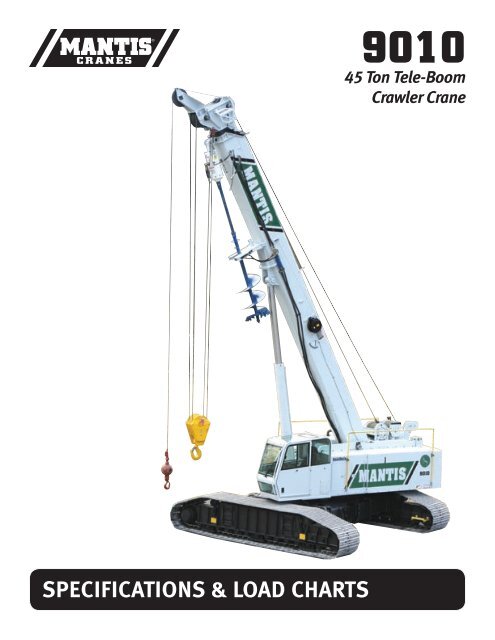
SPECIFICATIONS & LOAD CHARTS<br />
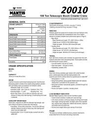
<strong>9010</strong><br />
<strong>45</strong> Ton Tele-Boom<br />
Crawler Crane
MANTIS2<br />
For over thirty years, Mantis <strong>tele</strong>scopic <strong>boom</strong> <strong>crawler</strong> <strong>crane</strong>s have set the global standard<br />
with the dependability, versatility and performance expected of a market leader. Mantis <strong>crane</strong>s<br />
are built like no other. At their hearts, are massive steel fabrications, over-sized to handle the<br />
toughest jobs, year-in and year-out. Powerful state-of-the-art hydraulics coupled with diesel<br />
engines available in a choice of sizes match perfectly to meet the most rigorous of project<br />
demands.<br />
Mantis remains one of the few <strong>crane</strong> makers prepared and equipped to work with contractors<br />
and project engineers to develop customized lifting solutions that meet the most unusual<br />
of project challenges. Thanks to the versatile combination of heavy duty <strong>tele</strong>scopic <strong>boom</strong>s,<br />
hydraulically extendable <strong>crawler</strong>s, and extremely compact dimensions, Mantis <strong>crane</strong>s<br />
can often get closer to a job than bulkier, fixed length lattice <strong>boom</strong> <strong>crawler</strong> <strong>crane</strong>s or<br />
rubber-tired <strong>crane</strong>s that need outriggers to work effectively.<br />
No other <strong>crane</strong> combines so many valuable features:<br />
• Pick-and-carry the full <strong>crane</strong> load chart through 360°.<br />
• Lift and walk...even with tracks retracted.<br />
• Climb steeper grades more safely, thanks to minimized counterweight<br />
and low center of gravity.<br />
• Pull through deep mud without bogging down.<br />
• Telescope or lift the <strong>boom</strong> with a full load on the hook.<br />
• Save time and money on the job due to its low clearance height, retract<br />
on-the-fly tracks and <strong>tele</strong>scopic <strong>boom</strong>.<br />
• Independent hydrostatic track drive allows pivot turns to run rings around RTs.<br />
• Hydraulic tool circuit option powers wide choice of Mantis-approved tools.<br />
• New luxury cab with state-of-the-art operator aids.<br />
• Saves time and money on deployment and shipping with less haul vehicles,<br />
less time wasted on <strong>boom</strong> erection and fewer personnel on the erection crew.
<strong>9010</strong><br />
3
ON THE JOB<br />
MANTIS ® <strong>9010</strong><br />
<strong>45</strong> TON TELE-BOOM CRAWLER CRANE<br />
The new Mantis <strong>9010</strong> combines the rugged dependability<br />
of its sister-machine, the job-proven Mantis 8012 with<br />
increased capacity and reach. Based upon performanceproven<br />
components and fabrications, the <strong>9010</strong> is assured<br />
of the same bullet-proof reputation of its peers. Rated at<br />
<strong>45</strong>-<strong>ton</strong> (40-<strong>ton</strong>ne) lifting capacity at a full 10ft (3m) radius,<br />
the Mantis <strong>9010</strong> is the envy of its imitators. For like all<br />
Mantis <strong>crane</strong>s, the <strong>9010</strong> is purpose-designed from the<br />
ground-up, not an assortment of pieces borrowed from<br />
other products.<br />
Like all Mantis <strong>crane</strong>s, the <strong>9010</strong> can pick-and-carry its<br />
entire load chart – through 360°. It can even walk with<br />
<strong>45</strong>-<strong>ton</strong>s (40-<strong>ton</strong>nes) suspended when equipped with zero<br />
counterweight. And should narrow roadways demand lifting<br />
with tracks retracted for 11-12ft (3.35-3.66m) overall width,<br />
the <strong>9010</strong> can still walk with 75,000lbs (34-<strong>ton</strong>nes), swing<br />
it through 360° and deploy the full 105ft (32m) full power<br />
main <strong>boom</strong>.<br />
For its size and power, the Mantis <strong>9010</strong> has an extraordinarily<br />
low center of gravity with a minimum overhead clearance<br />
height of just 10ft (3.05m). And like all Mantis <strong>crane</strong>s, the<br />
<strong>9010</strong> doesn’t depend upon massive counterweighting for<br />
its strength – for big counterweights are a liability when<br />
climbing grades! The <strong>9010</strong> can walk with full <strong>boom</strong> and<br />
jib deployed, delivering an impressive 159ft (48.5m)<br />
maximum tip height. Such is the stability of the <strong>9010</strong> that<br />
it can operate with the fully <strong>tele</strong>scoped main <strong>boom</strong> laid out<br />
completely horizontal!<br />
KEY FEATURES INCLUDE:<br />
• <strong>45</strong>-<strong>ton</strong>s (40-<strong>ton</strong>nes) pick-and-carry capacity at 10ft (3m) radius thru 360°.<br />
• Sequence-synchronized four-section full power <strong>boom</strong> of 105ft (32m)<br />
length.<br />
• Lattice <strong>boom</strong> extensions and offsettable jibs for up to 159ft (48.5m) tip<br />
height.<br />
• 215 hp (168kW) diesel engine standard.<br />
• Low ground bearing pressure of 6.3 psi (0.<strong>45</strong> kg/cm2) minimum.<br />
• Mantis-engineered in-situ auger options with optional hydraulic tool circuit.<br />
• Fast two-speed independent hydrostatic track drive to 3 mph (4.8 km/hr).<br />
• Full <strong>boom</strong> <strong>tele</strong>scoping and <strong>boom</strong> lift under full hook load.<br />
• 11-to-12ft (3.35-3.66m) minimum travel width according to tracks selected.<br />
• Extraordinary 10ft (3.05m) overhead clearance height.<br />
• New deluxe operators cab and standard LMI and Anti-Two-Block devices.<br />
• 90-94,000lb (41-42.6-<strong>ton</strong>ne) shipping weight fully equipped – hauls as a<br />
single, ready-to-work load.<br />
• Steep 68% gradeability thanks to low center of gravity.<br />
• Hydraulic on-the-fly track frame retraction and extension.<br />
• Powerful 17,500lb (7.9-<strong>ton</strong>ne) pla<strong>net</strong>ary main winch with full load single<br />
line speeds to 228 fpm (69.5 mpm) or 489 fpm (149 mpm) no-load speed.<br />
• Optional Mantis WP-750 Heavy Duty Work Platform for up to 146ft<br />
(44.5m) working height.<br />
• High 13ins (330mm) ground clearance helps avoid damage and snagging.<br />
PETRO CHEM<br />
Drill rig sites are busy, congested job sites. The Mantis <strong>crane</strong>s ability to <strong>tele</strong>scope the entire<br />
load chart or lift it on the <strong>boom</strong> hoist cylinder can prove invaluable threading loads between<br />
obstructions. Being able to walk a load into place, narrow the <strong>crane</strong> with tracks retracted,<br />
change <strong>boom</strong> length in seconds and pivot on the spot puts the Mantis in a different league from<br />
cumbersome lattice <strong>crawler</strong>s and RTs with their big footprints and lifting limitations.<br />
4
ON THE JOB<br />
POWERLINE<br />
Whenever possible, electric utility power transmission grids are<br />
planned in straight lines – whether hills, rocks, ridges or rivers<br />
are in their way. For utility contractors being ready for whatever<br />
may lay in the way means choosing a <strong>crane</strong> that can cope with<br />
almost any terrain....pick-and-carry towers, drill their foundations<br />
and string the wires.<br />
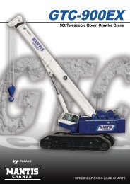
EASY LOADER<br />
The <strong>9010</strong> closes down to a width of 12ft (3.66m), a clearance height<br />
of 10ft (3.05m) and an overall length of just 43ft 7ins (13.29m). It can<br />
ship with counterweight intact and scales in at 94,000lbs (42.6-<strong>ton</strong>nes)<br />
fully rigged with block, ball, jib & extension and auger kit. In most cases<br />
it can be loaded on a single trailer with no disassembly in a matter of<br />
minutes and arrive at the job site ready to work.<br />
5
SPECIFICATIONS<br />
MANTIS ® <strong>9010</strong><br />
<strong>45</strong> TON TELE-BOOM CRAWLER CRANE<br />
Shoe<br />
Width<br />
24 in<br />
(609 mm)<br />
30 in<br />
(762 mm)<br />
36 in<br />
(900 mm)<br />
WIDTHS, WEIGHTS, AND GROUND PRESSURES*<br />
Retracted<br />
11 ft 0 in<br />
(3.35 m)<br />
11 ft 6 in<br />
(3.51 m)<br />
12 ft 0 in<br />
(3.66 m)<br />
Overall Width<br />
Extended<br />
17 ft 2 in<br />
(5.22 m)<br />
17 ft 8 in<br />
(5.39 m)<br />
18 ft 4 in<br />
(5.59 m)<br />
Area<br />
9,360 in 2<br />
(6.04 m²)<br />
11,700 in 2<br />
(7.55 m²)<br />
14,040 in 2<br />
(9.06 m²)<br />
Ground<br />
Pressure<br />
9.6 psi<br />
(0.68 kg/cm²)<br />
7.9 psi<br />
(0.51 kg/cm²)<br />
6.7 psi<br />
(0.47 kg/cm²)<br />
* Crane equipped with: 105 ft <strong>boom</strong>, extension, jib, <strong>45</strong> <strong>ton</strong> hook block, 12 <strong>ton</strong> headache ball<br />
Working<br />
Weight<br />
89,950 lb<br />
(40,800 kg)<br />
91,930 lb<br />
(41,700 kg)<br />
93,904 lb<br />
(42,590 kg)<br />
A<br />
B<br />
C<br />
D<br />
E<br />
F<br />
G<br />
H<br />
I<br />
J<br />
K<br />
L<br />
M<br />
N<br />
O<br />
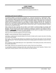
PRINCIPAL DIMENSIONS<br />
Length<br />
42 ft 9 in<br />
(Counterweight Removed) (13.02 m)<br />
CL Front Track Drive to CL 8 ft 2 in<br />
Rotation<br />
(2.46 m)<br />
CL Rear Track Drive to CL 8 ft 2 in<br />
Rotation<br />
(2.46 m)<br />
Track Length<br />
19 ft 0 in<br />
(5.79 m)<br />
Boom Length to CL Rotation<br />
30 ft 10 in<br />
(9.40 m)<br />
Tailswing<br />
12 ft 10 in<br />
(3.91 m)<br />
Overall Length<br />
43 ft 7 in<br />
(13.29 m)<br />
Ground to Top of Engine Cover<br />
8 ft 4 in<br />
(2.54 m)<br />
Track Height<br />
42 in<br />
(1 067 mm)<br />
Ground Clearance<br />
13 in<br />
(330 mm)<br />
Ground to Bottom of Cab<br />
48 in<br />
(1 219 mm)<br />
Maximum Overall Height<br />
10 ft 0 in<br />
(3.05 m)<br />
Track Width<br />
36 in<br />
(900 mm)<br />
Overall Width<br />
12 ft 0 in<br />
(Tracks Retracted)<br />
(3.66 m)<br />
Overall Working Width<br />
18 ft 4 in<br />
(5.59 m)<br />
6
SPECIFICATIONS<br />
MANTIS ® <strong>9010</strong><br />
<strong>45</strong> TON TELE-BOOM CRAWLER CRANE<br />
STANDARD CRANE AND EQUIPMENT<br />
Boom<br />
The <strong>boom</strong> consists of four full power sections, 34 ft 0 in (10.4 m)<br />
retracted and 105 ft 0 in (32 m) fully extended. Maximum tip height<br />
is 111 ft (33.8 m).<br />
Boom Telescoping & Elevating Systems<br />
The elevating system features a cylinder and counterbalance lock valves<br />
which provide <strong>boom</strong> elevations from -1° to 78°. The <strong>tele</strong>scoping system<br />
features two double-acting hydraulic cylinders and counterbalance lock<br />
valves.<br />
Boom Head<br />
Six 19 in (483 mm) diameter, cast nylon sheaves on heavy-duty roller<br />
bearings are mounted in the <strong>boom</strong> head.<br />
Load Moment Indicator & Anti-Two Block 1<br />
Standard Rated Capacity Limiter and Anti-Two Block system includes<br />
audio and video warnings and control function shutdown. System’s LCD<br />
screen provides a continuous electronic display of working <strong>boom</strong> length,<br />
<strong>boom</strong> angle, working load radius, tip height, parts-of-line (operator set),<br />
machine track configuration, relative load moment, maximum permissible<br />
load and actual load. The standard Work Area Definition audio and<br />
video warnings aid the operator in avoiding job-site obstructions by<br />
pre-setting and defining the work area. The anti-two block weight allows<br />
quick reeving of hook blocks.<br />
SUPERSTRUCTURE<br />
Frame<br />
The frame is an all-steel, welded structure, precision machined to accept<br />
attachment of the <strong>boom</strong> and swing devices.<br />
Operator’s Cab<br />
The fully-enclosed, air conditioned all-steel modular cab includes a<br />
lockable swinging door, acoustical lining, anti-slip floor and tinted safety<br />
glass. Sliding windows are located in the cab door and cab <strong>boom</strong> side.<br />
A vent window is positioned in the rear of the cab. Grab bars and steps<br />
are appropriately located for easy access to the cab. Erectable swing<br />
barricades are attached to the superstructure. Rear view cameras are<br />
appropriately located as are work lights.<br />
Standard cab accessories include a two-speed windshield wiper, top<br />
glass wiper, defroster, heater, circulating fan, adjustable hand and foot<br />
throttles, six-way adjustable fabric seat with headrest, seat belt, dome<br />
light, and a dry-chemical fire extinguisher.<br />
Instrumentation<br />
Dash instrumentation features a tachometer, voltmeter, oil pressure<br />
gauge, temperature gauge, hour meter and fuel gauge. Indicators are<br />
provided for <strong>crane</strong> level, load moment, drum rotation, air filter restriction,<br />
hydraulic oil temperature and filter restriction, engine oil pressure and<br />
temperature.<br />
A termination switch is located in the seat and armrest and is capable of<br />
immediately disabling all hydraulic functions as the operator rises from<br />
the seat or it can be activated by lifting the left hand armrest.<br />
Control<br />
Two-way hydraulic joysticks mounted in the operator’s seat armrests<br />
control swing, auxiliary hoist, main winch and <strong>boom</strong> hoist. Four twoway<br />
hydraulic foot pedals control travel, swing service brake and <strong>boom</strong><br />
<strong>tele</strong>scoping functions. A fifth pedal controls engine speed.<br />
Counterweight<br />
The single piece 15,000 lb (6,804 kg) counterweight can be removed and<br />
installed via a pendant attached to the <strong>boom</strong>.<br />
Swing<br />
The superstructure rotates 360° around a shear ball slew bearing with<br />
an external gear that matches with the swing drive pinion and bolts to the<br />
superstructure and the carbody. The hydraulic swing drive powers the<br />
system and consists of a gear motor driving into a pla<strong>net</strong>ary reducer with<br />
a shaft mounted pinion providing infinitely variable speeds of up to 3 rpm.<br />
Swing braking is achieved through a “failsafe”, hydraulically released,<br />
spring applied, multi-disc wet brake which includes a foot applied service<br />
brake. The brake can be electrically actuated through a cab mounted<br />
switch into a “locked-on” (parking) mode. A two position house lock<br />
system is included. Regular lubrication of the bearing is achieved through<br />
a cab mounted grease applicator.<br />
Fuel System<br />
An 80 US gal (303 l) tank is bolted to the superstructure. The fuel filtration<br />
system consists of an inline fuel/water separator as well as an engine<br />
mounted fuel filter.<br />
Hydraulic System<br />
The load sensing, open-loop hydraulic system is served by two variable<br />
volume pumps mounted in tandem. The pumps are horsepower limiting<br />
providing a maximum output of 168 gpm (636 l/min) @ 2,200 rpm and<br />
maximum operating pressure of 4,850 psi (339.5 kg/cm²). An extra circuit<br />
is included for ready adaptation to hydraulic accessories.<br />
The system includes two pilot operated valve banks that are pressure<br />
and flow compensated. The 300 US gal (1 136 l) capacity hydraulic oil<br />
reservoir has a spin-on filler-breather cap, external sight gauge, clean-out<br />
access and a sump type drain. An air to oil remote mounted cooler provides<br />
oil cooling with thermostatically-controlled, electrically driven fans.<br />
Hydraulic oil filtering is achieved with two 3 micron full flow cartridge type<br />
filters designed to return in-tank with bypass protection and an electronic<br />
bypass indicator.<br />
(System pressure test ports with quick disconnect fittings are provided for<br />
diagnostics.)<br />
7
SPECIFICATIONS<br />
MANTIS ® <strong>9010</strong><br />
<strong>45</strong> TON TELE-BOOM CRAWLER CRANE<br />
MAIN HOIST<br />
Pla<strong>net</strong>ary geared two-speed winch includes a bent axis, variable displacement hydraulic motor and a multi-disc internal brake.<br />
Wire Rope: 600 ft (183 m) 5/8 in (16 mm) 6 x 37 EIPS, IWRC, RRL. Line pulls are not based on wire rope strength. Drum rotation indicator is standard.<br />
Rope<br />
Layer<br />
Maximum Line Pull No Load Line Speed Full Load Line Speed Pitch Diameter Layer Total<br />
1 17,500 lb 7,940 kg 384 ft/min 117.0 m/min 179 ft/min 54.6 m/min 11.4 in 288.9 mm 76 ft 23.2 m 76 ft 23.2 m<br />
2 15,700 lb 7,120 kg 414 ft/min 126.2 m/min 193 ft/min 58.8 m/min 12.5 in 316.3 mm 83 ft 25.3 m 159 ft 48.5 m<br />
3 14,300 lb 6,490 kg 433 ft/min 132.0 m/min 202 ft/min 61.6 m/min 13.5 in 343.6 mm 91 ft 27.7 m 250 ft 76.3 m<br />
4 13,100 lb 5,940 kg <strong>45</strong>1 ft/min 137.5 m/min 210 ft/min 64.0 m/min 14.6 in 370.9 mm 98 ft 29.9 m 348 ft 106.1 m<br />
5 12,100 lb 5,490 kg 482 ft/min 146.9 m/min 225 ft/min 68.6 m/min 15.7 in 398.3 mm 105 ft 32.0 m <strong>45</strong>3 ft 138.1 m<br />
6 11,300 lb 5,130 kg 489 ft/min 149.0 m/min 228 ft/min 69.5 m/min 16.8 in 425.6 mm 112 ft 34.1 m 566 ft 172.5 m<br />
Rope<br />
Layer<br />
AUXILIARY HOIST<br />
Pla<strong>net</strong>ary geared single-speed winch includes a bent axis, variable displacement hydraulic motor and a multi-disc internal brake.<br />
Wire Rope: 350 ft (107 m) 5/8 in (16 mm) 6 x 37 EIPS, IWRC, RRL. Line pulls are not based on wire rope strength. Drum rotation indicator is standard.<br />
Maximum Line Pull Full Load Line Speed Pitch Diameter Layer Total<br />
1 12,000 lb 5,440 kg 182 ft/min 55.5 m/min 10.4 in 263.5 mm 65 ft 19.8 m 65 ft 19.8 m<br />
2 10,700 lb 4,850 kg 198 ft/min 60.4 m/min 11.5 in 290.9 mm 66 ft 20.1 m 126 ft 38.4 m<br />
3 9,800 lb 4,<strong>45</strong>0 kg 208 ft/min 63.4 m/min 12.5 in 318.2 mm 74 ft 22.6 m 199 ft 60.7 m<br />
4 9,000 lb 4,080 kg 217 ft/min 66.1 m/min 13.6 in 3<strong>45</strong>.5 mm 81 ft 24.7 m 281 ft 85.6 m<br />
5 8,300 lb 3,760 kg 233 ft/min 71.0 m/min 14.7 in 372.9 mm 89 ft 27.1 m 370 ft 112.8 m<br />
STANDARD CRANE WITH 4 SECTION 105 ft 0 in (32 m) BOOM,<br />
1 PIECE COUNTERWEIGHT AND 36 in (900 mm) TRACK SHOES<br />
STANDARD ENGINE<br />
Cummins QSB215 (U. S. EPA Tier 3)<br />
Noise Emissions: Top 96.3 dBa (excludes noise from intake, exhaust, cooling system and driven components)<br />
Type 6 Cylinder Water Cooled Weight (Wet) 1056 lb (479 kg) Aspiration Turbocharged & Aftercooled<br />
Displacement 360 cu in (5.9 l) Oil Capacity 17.2 US quarts (16.3 l) Air filter Dry Type<br />
Bore 4.02 in (102 mm) Rated Horsepower 215 @ 2200 rpm Electrical system 12 volt<br />
Stroke 4.72 in (120 mm) Peak Torque 692 ft/lb @ 1500 rpm Alternator 100 amp<br />
MACHINE WEIGHTS<br />
89,900 lb 40,780 kg<br />
Crane Less Counterweight and Track Frames<br />
Counterweight 15,000 lb 6,800 kg<br />
Track Frames, 2 pieces 11,800 lb (5,350 kg) each 23,600 lb 10,700 kg<br />
OPTIONAL EQUIPMENT<br />
30 ft (9.14 m) Lattice Extension 1,700 lb 771 kg<br />
20 ft (6.10 m) Jib (connects to head of Lattice Extension ONLY) 700 lb 318 kg<br />
Auxiliary Nose Sheave 210 lb 95 kg<br />
12 <strong>ton</strong> (11 mt) Headache Ball 404 lb 183 kg<br />
<strong>45</strong> <strong>ton</strong> (40 mt) Hook Block 1,200 lb 544 kg<br />
Auxiliary Winch with Standard Rope 684 lb 311 kg<br />
Auger Ready Package 440 lb 200 kg<br />
Complete Auger Package 1,520 lb 690 kg<br />
60 in (1 524 mm) Auger Kelly Bar 120 lb 54 kg<br />
72 in (1 829 mm) Auger Kelly Bar 140 lb 64 kg<br />
* Deduction from Standard Crane Weight<br />
8
SPECIFICATIONS<br />
MANTIS ® <strong>9010</strong><br />
<strong>45</strong> TON TELE-BOOM CRAWLER CRANE<br />
UNDERCARRIAGE<br />
Carbody<br />
The welded steel, box type carbody is fabricated with square axles to<br />
accept the <strong>crawler</strong> side frames. The top surface is precision machined to<br />
receive the swing bearing.<br />
Side Frames<br />
Two welded steel removable side frames are paired with a track group<br />
consisting of two top and thirteen bottom oil-filled & sealed rollers. Each<br />
frame includes an oil-filled, self-lubricating idler and spring type, track<br />
tensioning device. Standard track shoes are 36 in (900 mm) wide, 3-bar<br />
semi-grousers. Optional shoes are available in 24 in (609 mm) and 30 in<br />
(742 mm) widths flat pad and semi grouser configurations. 30 in flat pads<br />
are also available. The side frames extend and retract hydraulically and<br />
are electrically controlled from the cab.<br />
OPTIONAL EQUIPMENT<br />
Boom Attachments<br />
• Boom Extension: 30 ft 0 in (9.1 m), lattice type swingaway that stores<br />
alongside of the <strong>boom</strong> base section and can be used with or without<br />
the optional 20 ft 0 in (6.1 m) jib. Head contains two 19 in (483 mm)<br />
diameter high strength cast nylon sheaves mounted on heavy-duty<br />
roller bearings, reeving up to 2 parts of wire rope. With the extension<br />
deployed the maximum tip height is 140 ft (42.7 m).<br />
• Boom Jib: 20 ft 0 in (6.1 m) lattice type swingaway, attaches to<br />
and stores alongside the extension and can only be used with the<br />
extension deployed. Offsets are at 15° & 30°. With jib and extension<br />
deployed the maximum tip height is 159 ft (48.5 m).<br />
• Auxiliary Nose Sheave: Quick reeve, single 19 in (483 mm) diameter<br />
high-strength, cast nylon sheave mounted on a heavy-duty roller bearing.<br />
• Wire Rope: rotation resistant, (non-spin,) Dyform-18 HSLR.<br />
• Headache Ball: 12 <strong>ton</strong> (11 mt) ball includes a swivel hook with a<br />
safety latch.<br />
• Hook Block: <strong>45</strong> <strong>ton</strong> (40 mt) hook block consists of four 19 in (483 mm)<br />
diameter sheaves mounted on heavy-duty roller bearings with a swivel<br />
hook and safety latch.<br />
Travel<br />
Each side frame contains a pilot controlled, two-speed track drive. The<br />
drives are hydraulic pis<strong>ton</strong> motors which propel the <strong>crane</strong> at a low speed<br />
of 2.0 mph (3.2 km/hr) and at a high speed of 3.0 mph (4.8 km/hr).<br />
The internal brake system is spring applied and automatically released<br />
upon actuation of the travel system.<br />
The hydraulic travel system provides skid steering and track<br />
counter- rotation and achieves an unladen gradeability of 68%.<br />
• Auger Ready Package: includes hoses, fasteners and stowage<br />
bracket assembly mounted to the base section of the <strong>boom</strong> with a flow<br />
capability of 40 gpm.<br />
• Complete Auger Package: adds a two speed auger motor/gear box<br />
and one 60 in (1 524 mm) kelly bar to the Auger Ready Package.<br />
• Tool Circuit: provides 5 gpm (19 l/min) and 10 gpm (38 l/min) at 2,500<br />
psi (176 kg/cm²) through a 50 ft (15.24 m) twin hose reel with quick<br />
disconnect fittings to operate open center tools.<br />
Other Options<br />
• Free Fall Hoists: all winches are available in free fall and controlled<br />
free fall configurations.<br />
• Crane Cab Access Walkway: a pair of 54.5 in (1 384 mm) wide x 25 in<br />
(635 mm) deep walkways which attach to both the front and rear of the<br />
carbody and allow for easier egress and ingress to the operator’s cab<br />
when the <strong>crane</strong>’s upper rotating frame is not aligned front to rear.<br />
• Model WP750 Work Platform: 36 in x 72 in (914 mm x 1 828 mm), allsteel,<br />
two-person platform with a maximum capacity of 750 lb (340 kg).<br />
A test weight and <strong>boom</strong> head adapter are included in the package. Operation<br />
and control are by the <strong>crane</strong> operator from the cab. Radio (RF)<br />
controls to enable remote operation from the platform are available.<br />
(See separate WP750 Specification for a complete description of standard<br />
and optional Work Platform equipment.)<br />
Hydraulic<br />
1<br />
Load moment indicating and anti-two block systems are operator aids and must never be used in lieu of job site lift planning calculations by the operator which must take into account ground conditions, weather and all other environmental factors prevailing at the time of the lift. Prices<br />
and specifications are subject to change at any time without prior notice and are for factory installation at time of original manufacture. F.O.B Plant; Richlands, VA 24641. Illustrations and photographs may show optional equipment. Supercedes all previous issues. Please see www.<br />
mantis<strong>crane</strong>s.com for most current information.<br />
9
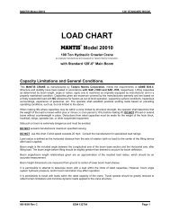
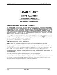
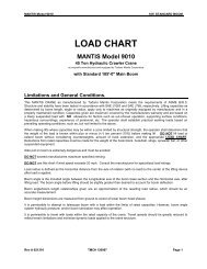
LOAD CHARTS<br />
MANTIS ® <strong>9010</strong><br />
<strong>45</strong> TON TELE-BOOM CRAWLER CRANE<br />
105 FT 0 IN MAIN BOOM, 30 FT EXTENSION & 20 FT JIB<br />
60 in<br />
(1.5 m)<br />
60 in<br />
(1.5 m)<br />
60 in<br />
(1.5 m)<br />
60 in<br />
(1.5 m)<br />
CAUTION<br />
THESE CHART VALUES ARE ONLY A GUIDE AND MUST NOT BE USED TO OPERATE THE CRANE. USE ONLY THE IN CAB LOAD CHARTS AND OPERATOR’S MANUAL FURNISHED WITH THE CRANE. 10
LOAD CHARTS<br />
MANTIS ® <strong>9010</strong><br />
<strong>45</strong> TON TELE-BOOM CRAWLER CRANE<br />
LIFTING CAPACITIES<br />
IN THOUSANDS OF POUNDS; 360°, 75% OF TIPPING, FIRM & LEVEL GROUND<br />
MAIN BOOM with TRACKS FULLY EXTENDED<br />
15,000 lb COUNTERWEIGHT ZERO COUNTERWEIGHT<br />
RADIUS (ft)<br />
10<br />
12<br />
15<br />
20<br />
25<br />
30<br />
35<br />
40<br />
<strong>45</strong><br />
50<br />
55<br />
60<br />
65<br />
70<br />
75<br />
80<br />
85<br />
90<br />
95<br />
100<br />
MAIN BOOM LENGTH (ft)<br />
MAIN BOOM LENGTH (ft)<br />
RADIUS (ft)<br />
34.0 41.9 49.8 57.7 69.5 81.3 93.2 105.0 34.0 41.9 49.8 57.7 69.5 81.3 93.2 105.0<br />
90.0 80.0 70.0 60.8* 90.0 80.0 70.0 60.8*<br />
68.1° 72.5° 75.3° 77.4° 68.1° 72.5° 75.3° 77.4°<br />
10<br />
85.0 78.0 64.0 55.0 48.0* 74.5 72.0 64.0 55.0 48.0*<br />
64.4° 69.5° 72.9° 75.3° 77.9° 64.4° 69.5° 72.9° 75.3° 77.9°<br />
12<br />
66.0 64.0 57.0 48.3 <strong>45</strong>.0 39.3* 52.2 51.5 50.1 47.9 <strong>45</strong>.0 39.3*<br />
58.5° 65.0° 69.2° 72.2° 75.3° 77.5° 58.5° 65.0° 69.2° 72.2° 75.3° 77.5°<br />
15<br />
<strong>45</strong>.0 44.7 44.4 40.0 36.6 31.9 30.0 27.7* 30.4 28.5 26.9 24.6 25.8 26.5 30.0 27.7*<br />
47.6° 57.1° 62.9° 66.9° 71.0° 73.9° 76.0° 77.6° 47.6° 57.1° 62.° 66.9° 71.0° 73.9° 76.0° 77.6°<br />
20<br />
33.2 33.0 32.7 32.1 30.6 26.5 25.0 22.7 20.0 19.6 19.2 18.8 19.5 20.2 20.7 21.0<br />
34.0° 48.2° 56.1° 61.3° 66.5° 70.1° 72.8° 74.8° 34.0° 48.2° 56.1° 61.3° 66.5° 70.1° 72.8° 74.8°<br />
25<br />
24.9 24.5 24.1 23.3 23.6 22.7 21.2 19.0 14.4 14.2 14.0 13.8 14.6 15.2 15.7 16.0<br />
4.9° 37.8° 48.6° 55.3° 61.9° 66.3° 69.5° 71.9° 4.9° 37.8° 48.6° 55.3° 61.9° 66.3° 69.5° 71.9°<br />
30<br />
18.2 17.8 16.7 17.9 18.5 18.1 16.2 10.7 10.3 9.9 10.2 10.5 10.9 11.8<br />
23.5° 40.1° 48.9° 57.1° 62.4° 66.1° 69.0° 23.5° 40.1° 48.9° 57.1° 62.4° 66.1° 69.0°<br />
35<br />
13.1 12.5 14.1 14.7 15.1 14.0 7.5 7.1 7.4 8.3 9.1 9.8<br />
29.6° 41.7° 51.9° 58.3° 62.7° 66.0° 29.6° 41.7° 51.9° 58.3° 62.7° 66.0°<br />
40<br />
10.2 9.8 11.3 11.9 12.3 12.2 5.9 5.6 6.2 6.7 7.2 7.6<br />
11.9° 33.3° 46.4° 53.4° 59.2° 63.0° 11.9° 33.3° 46.4° 53.4° 59.2° 63.0°<br />
<strong>45</strong><br />
8.2 9.0 9.5 10.3 10.7 4.5 4.9 5.2 5.4 5.6<br />
22.0° 40.2° 49.4° 55.5° 59.8° 22.0° 40.2° 49.4° 55.5° 59.8°<br />
50<br />
7.9 8.4 8.8 9.0 3.0 3.4 3.8 4.0<br />
33.1° 44.5° 51.6° 56.6° 33.1° 44.5° 51.6° 56.6°<br />
55<br />
6.2 6.8 7.2 7.5 2.0 2.3 2.6 2.8<br />
24.2° 39.1° 47.5° 53.2° 24.2° 39.1° 47.5° 53.2°<br />
60<br />
5.1 5.7 6.1 6.4 1.1 1.4 1.6 1.9<br />
8.2° 33.0° 43.1° 49.7° 8.2° 33.0° 43.1° 49.7°<br />
65<br />
4.7 5.1 5.3<br />
25.6° 38.3° 46.0°<br />
NR NR NR 70<br />
3.9 4.2 4.4<br />
14.8° 32.9° 42.0°<br />
NR NR NR 75<br />
3.3 3.5<br />
26.5° 37.7°<br />
NR NR 80<br />
2.5 2.7<br />
18.1° 32.8°<br />
NR NR 85<br />
2.0<br />
27.3°<br />
NR 90<br />
1.5<br />
20.3°<br />
NR 95<br />
1.1<br />
8.7°<br />
NR 100<br />
* Capacity based on maximum obtainable <strong>boom</strong> angle.<br />
° Boom angles are stated in degrees.<br />
NR = No Rating for this position.<br />
CAUTION<br />
THESE CHART VALUES ARE ONLY A GUIDE AND MUST NOT BE USED TO OPERATE THE CRANE. USE ONLY THE IN CAB LOAD CHARTS AND OPERATOR’S MANUAL FURNISHED WITH THE CRANE. 11
LOAD CHARTS<br />
MANTIS ® <strong>9010</strong><br />
<strong>45</strong> TON TELE-BOOM CRAWLER CRANE<br />
LIFTING CAPACITIES<br />
IN THOUSANDS OF POUNDS; 360°, 75% OF TIPPING, FIRM & LEVEL GROUND<br />
RADIUS<br />
(ft)<br />
10<br />
12<br />
15<br />
20<br />
25<br />
30<br />
35<br />
40<br />
<strong>45</strong><br />
50<br />
55<br />
60<br />
65<br />
70<br />
MAIN BOOM with TRACKS FULLY RETRACTED<br />
15,000 lb COUNTERWEIGHT<br />
MAIN BOOM LENGTH (ft)<br />
34.0 41.9 49.8 57.7 69.5 81.3 93.2 105.0<br />
75.0 79.8 70.0 60.8*<br />
68.1° 72.5° 75.3° 77.4°<br />
54.4 55.9 55.4 55.0 48.0*<br />
64.4° 69.5° 72.9° 75.3° 77.9°<br />
43.0 42.5 41.2 39.5 40.4 41.5<br />
58.5° 65.0° 69.2° 72.2° 75.3° 77.5°<br />
27.9 26.7 25.6 24.7 25.8 27.2 28.4 29.5<br />
47.6° 57.1° 62.9° 66.9° 71.0° 73.9° 76.0° 77.6°<br />
18.8 18.5 18.2 18.0 18.6 18.9 19.8 20.7<br />
34.0° 48.2° 56.1° 61.3° 66.5° 70.1° 72.8° 74.8°<br />
13.2 13.1 12.9 12.7 13.0 13.4 13.6 14.0<br />
4.9° 37.8° 48.6° 55.3° 61.9° 66.3° 69.5° 71.9°<br />
9.0 8.9 8.7 9.4 10.1 10.9 11.6<br />
23.5° 40.1° 48.9° 57.1° 62.4° 66.1° 69.0°<br />
6.4 6.2 6.8 7.5 8.7 9.4<br />
29.6° 41.7° 51.9° 58.3° 62.7° 66.0°<br />
5.3 5.1 5.8 6.2 6.9 7.5<br />
11.9° 33.3° 46.4° 53.4° 59.2° 63.0°<br />
3.9 4.3 4.9 5.4 5.8<br />
22.0° 40.2° 49.4° 55.5° 59.8°<br />
3.3 3.8 4.1 4.4<br />
33.1° 44.5° 51.6° 56.6°<br />
2.1 2.6 2.9 3.2<br />
24.2° 39.1° 47.5° 53.2°<br />
1.2 1.7 2.0 2.3<br />
8.2° 33.0° 43.1° 49.7°<br />
1.0 1.2 1.5<br />
25.6° 38.3° 46.0°<br />
RADIUS<br />
(ft)<br />
10<br />
12<br />
15<br />
20<br />
25<br />
30<br />
35<br />
40<br />
<strong>45</strong><br />
50<br />
55<br />
60<br />
65<br />
70<br />
Boom<br />
Angle<br />
30’ EXTENSION & 20’ JIB<br />
with TRACKS FULLY EXTENDED<br />
15,000 lb COUNTERWEIGHT<br />
30’ EXTENSION 20’ JIB<br />
Total Boom Length (ft)<br />
64.0 to<br />
105.0<br />
Jib Offset Angles<br />
> 105.0 0° 15° 30°<br />
* Capacity based on maximum obtainable <strong>boom</strong> angle.<br />
° Boom angles are stated in degrees.<br />
ZERO DEGREE BOOM ANGLE<br />
MAXIMUM CAPACITY<br />
with TRACKS FULLY EXTENDED<br />
Boom<br />
Angle<br />
78º 18.0 14.0 6.6 4.0 2.2 78º<br />
75º 13.6 12.4 6.5 4.0 2.1 75º<br />
72º 11.5 10.0 5.6 3.5 2.0 72º<br />
70º 10.1 9.1 5.1 3.2 1.9 70º<br />
68º 8.9 8.0 4.6 3.0 1.8 68º<br />
65º 8.0 7.5 4.2 2.8 1.8 65º<br />
62º 7.2 6.0 3.9 2.6 1.7 62º<br />
60º 6.7 4.4 3.5 2.4 1.7 60º<br />
58º 6.1 3.9 3.2 1.9 1.4 58º<br />
55º 5.8 3.0 2.6 1.3 1.0 55º<br />
52º 5.3 2.4 2.0 0.6 0.4 52º<br />
50º 5.1 1.9 1.3 0.3 0.2 50º<br />
48º 4.9 1.5 48º<br />
<strong>45</strong>º 4.6 1.0 <strong>45</strong>º<br />
WEIGHT REDUCTIONS<br />
LOAD HANDLING DEVICES<br />
HOOKBLOCK: <strong>45</strong> Ton - 4 Sheave<br />
OVERHAUL BALL: 12 Ton w/Swivel<br />
OPTIONAL HANDLING DEVICES<br />
1,086 lbs<br />
396 lbs<br />
30 ft. Extension - Stowed** 350 lbs<br />
30 ft. Extension - Erected** 2,000 lbs<br />
30 ft. Ext. and 20 ft. Jib - Stowed** 750 lbs<br />
30 ft. Ext. and 20 ft. Jib - Erected** 3,500 lbs<br />
Auxillary Nose Sheave**<br />
Auger Ready Package**<br />
Auger Package Complete - Stowed**<br />
Auger Package Complete - Erected**<br />
200 lbs<br />
225 lbs<br />
560 lbs<br />
1,200 lbs<br />
** Reduction of main <strong>boom</strong> capacities.<br />
15,000 lb COUNTERWEIGHT<br />
BOOM<br />
LOAD (lbs)<br />
RADIUS (ft)<br />
LENGTH (ft) (x 1000)<br />
BOOM<br />
LENGTH<br />
(ft)<br />
34.0 30.0 19.0 34.0<br />
41.9 37.9 14.9 41.9<br />
49.8 <strong>45</strong>.8 11.9 49.8<br />
57.7 53.7 9.4 57.7<br />
69.5 65.5 6.3 69.5<br />
81.3 77.3 3.8 81.3<br />
93.2 89.2 2.1 93.2<br />
105.0 101.0 1.0 105.0<br />
CAUTION<br />
THESE CHART VALUES ARE ONLY A GUIDE AND MUST NOT BE USED TO OPERATE THE CRANE. USE ONLY THE IN CAB LOAD CHARTS AND OPERATOR’S MANUAL FURNISHED WITH THE CRANE. 12
LOAD CHARTS<br />
MANTIS ® <strong>9010</strong><br />
<strong>45</strong> TON TELE-BOOM CRAWLER CRANE<br />
LIFTING CAPACITIES<br />
IN THOUSANDS OF POUNDS; 360°, 75% OF TIPPING, FIRM & LEVEL GROUND<br />
RADIUS (ft)<br />
10<br />
12<br />
15<br />
20<br />
25<br />
30<br />
35<br />
40<br />
<strong>45</strong><br />
50<br />
55<br />
60<br />
65<br />
70<br />
75<br />
80<br />
85<br />
90<br />
95<br />
100<br />
AUXILIARY NOSE SHEAVE with TRACKS FULLY EXTENDED<br />
15,000 lb COUNTERWEIGHT<br />
MAIN BOOM LENGTH (ft)<br />
34.0 41.9 49.8 57.7 69.5 81.3 93.2 105.0<br />
11.0 11.0 11.0 11.0<br />
68.1° 72.5° 75.3° 77.4°<br />
11.0 11.0 11.0 11.0 11.0<br />
64.4° 69.5° 72.9° 75.3° 77.9°<br />
11.0 11.0 11.0 11.0 11.0 11.0<br />
58.5° 65.0° 69.2° 72.2° 75.3° 77.5°<br />
11.0 11.0 11.0 11.0 11.0 11.0 11.0 11.0<br />
47.6° 57.1° 62.9° 66.9° 71.0° 73.9° 76.0° 77.6°<br />
11.0 11.0 11.0 11.0 11.0 11.0 11.0 11.0<br />
34.0° 48.2° 56.1° 61.3° 66.5° 70.1° 72.8° 74.8°<br />
11.0 11.0 11.0 11.0 11.0 11.0 11.0 11.0<br />
4.9° 37.8° 48.6° 55.3° 61.9° 66.3° 69.5° 71.9°<br />
11.0 11.0 11.0 11.0 11.0 11.0 11.0<br />
23.5° 40.1° 48.9° 57.1° 62.4° 66.1° 69.0°<br />
11.0 11.0 11.0 11.0 11.0 11.0<br />
29.6° 41.7° 51.9° 58.3° 62.7° 66.0°<br />
10.2 9.8 11.0 11.0 11.0 11.0<br />
11.9° 33.3° 46.4° 53.4° 59.2° 63.0°<br />
8.2 9.0 9.5 10.3 10.7<br />
22.0° 40.2° 49.4° 55.5° 59.8°<br />
7.9 8.4 8.8 9.0<br />
33.1° 44.5° 51.6° 56.6°<br />
6.2 6.8 7.2 7.5<br />
24.2° 39.1° 47.5° 53.2°<br />
5.1 5.7 6.1 6.4<br />
8.2° 33.0° 43.1° 49.7°<br />
4.7 5.1 5.3<br />
25.6° 38.3° 46.0°<br />
3.9 4.2 4.4<br />
14.8° 32.9° 42.0°<br />
3.3 3.5<br />
26.5° 37.7°<br />
2.5 2.7<br />
18.1° 32.8°<br />
2.0<br />
27.3°<br />
1.5<br />
20.3°<br />
1.1<br />
8.7°<br />
RADIUS (ft)<br />
10<br />
12<br />
15<br />
20<br />
25<br />
30<br />
35<br />
40<br />
<strong>45</strong><br />
50<br />
55<br />
60<br />
65<br />
70<br />
75<br />
80<br />
85<br />
90<br />
95<br />
100<br />
° Boom angles are stated in degrees.<br />
CAUTION<br />
THESE CHART VALUES ARE ONLY A GUIDE AND MUST NOT BE USED TO OPERATE THE CRANE. USE ONLY THE IN CAB LOAD CHARTS AND OPERATOR’S MANUAL FURNISHED WITH THE CRANE.<br />
13
MANTIS ® <strong>9010</strong><br />
<strong>45</strong> TON TELE-BOOM CRAWLER CRANE<br />
LOAD CHARTS<br />
MANTIS WP-750 WORK PLATFORM<br />
Limits of operation: Maximum load capacity = 750 lb<br />
Maximum radius when mounted on main <strong>boom</strong> = 75 ft<br />
CAUTION<br />
THESE CHART VALUES ARE ONLY A GUIDE AND MUST NOT BE USED TO OPERATE THE CRANE. USE ONLY THE IN CAB LOAD CHARTS AND OPERATOR’S MANUAL FURNISHED WITH THE CRANE.<br />
14
LOAD CHARTS<br />
MANTIS ® <strong>9010</strong><br />
<strong>45</strong> TON TELE-BOOM CRAWLER CRANE<br />
PARTS<br />
OF LINE<br />
MANTIS MODEL <strong>9010</strong><br />
WIRE ROPE LINE PULL CAPACITIES<br />
MAIN WINCH<br />
(pounds)<br />
AUX WINCH<br />
(pounds)<br />
PARTS<br />
OF LINE<br />
MAIN WINCH<br />
(pounds)<br />
1 11,771 11,771 5 58,855<br />
2 23,542 23,542 6 70,626<br />
3 35,313 N/A 7 82,397<br />
4 47,084 N/A 8 94,168<br />
5/8 inch diameter wire rope, 6 x 37 Class, EIP, IWRC<br />
PLEASE READ, UNDERSTAND, AND FOLLOW THE MANUALS FURNISHED WITH THE CRANE (OPERATOR’S AND SAFETY)<br />
AS WELL AS THE CAPACITY LIMITATIONS AND GENERAL CONDITIONS LISTED BELOW PRIOR TO OPERATION OF THE CRANE.<br />
FAILURE TO DO SO MAY RESULT IN AN ACCIDENT.<br />
Capacity Limitations and General Conditions:<br />
1. This MANTIS CRANE as manufactured, meets the requirements of<br />
ANSI B30.5 (2000). Structure and stability have been tested in accordance<br />
with SAE J1063 and SAE J765, respectively. Modifications<br />
to the <strong>crane</strong> or use of optional equipment other than specified by the<br />
manufacturer can result in a reduction of capacity.<br />
2. The main <strong>boom</strong> and auxliary <strong>boom</strong> head lifting capacities are determined<br />
by <strong>boom</strong> length and load radius. The extension and jib lifting<br />
capacities are determined by <strong>boom</strong> angle.<br />
3. Rated capacity loads given are maximum covered by the manufacturer’s<br />
warranty and are based on a freely suspended load with NO<br />
allowance for factors such as out-of-level operation, supporting surface<br />
conditions, hazardous surroundings, experience of personnel,<br />
etc. The operator shall establish practical working loads based on<br />
prevailing operating conditions, such as, but not limited to the above.<br />
4. All rated capacity loads shown apply to original equipment as supplied<br />
by SpanDeck, Inc.<br />
5. All rated capacity loads appearing above the bold line are based on<br />
structural strength; tipping should not be relied upon as a capacity<br />
limitation.<br />
6. All rated capacity loads appearing below the bold line are based on<br />
stability and do not exceed 75% of tipping.<br />
7. Deductions from rated capacities must be made for the weight of<br />
the hook block, headache ball, slings, spreader bar, and any other<br />
suspended equipment. See Lifting Capacity Deduction Chart for load<br />
handling devices supplied by SpanDeck, Inc.<br />
8. A properly calibrated and maintained Load Moment Indicator (LMI)<br />
system will indicate <strong>boom</strong> mounted and other suspended equipment.<br />
9. When making lifts where capacities may be within a zone limited by<br />
structural strength, the operator shall determine that the weight of<br />
the load is known within plus or minus (+/-) ten percent (10%) before<br />
making lift.<br />
10. It is permissible to attempt to <strong>tele</strong>scope <strong>boom</strong> with a load within the<br />
limits of rated capacities. However, <strong>boom</strong> <strong>tele</strong>scope system hydraulic<br />
pressure, and/or <strong>boom</strong> lubrication may affect operation.<br />
11. Side pull on <strong>boom</strong> is extremely dangerous and must be avoided.<br />
12. DO NOT exceed manufacturers maximum specified reeving.<br />
13. DO NOT lift load or extend <strong>boom</strong> without proper configuration of<br />
<strong>crane</strong> per load chart selected.<br />
14. DO NOT attempt to lift any load when wind speed exceeds 20 mph.<br />
Load moment indicating and anti-two block systems are operator aids and must never be used in lieu of job site lift planning calculations by the<br />
operator which must take into account ground conditions, weather and all other environmental factors prevailing at the time of the lift.<br />
Prices and specifications are subject to change at any time without prior notice and are for factory installation at the time of original manufacture.<br />
F.O.B Plant; Richlands, VA 24641. Illustrations and photographs may show optional equipment. Supercedes all previous issues.<br />
Please see www.mantis<strong>crane</strong>s.com for most current information.<br />
CAUTION<br />
THESE CHART VALUES ARE ONLY A GUIDE AND MUST NOT BE USED TO OPERATE THE CRANE. USE ONLY THE IN CAB LOAD CHARTS AND OPERATOR’S MANUAL FURNISHED WITH THE CRANE.<br />
15