SPECIFICATIONS & LOAD CHARTS - z3m.net
SPECIFICATIONS & LOAD CHARTS - z3m.net
SPECIFICATIONS & LOAD CHARTS - z3m.net

Create successful ePaper yourself
Turn your PDF publications into a flip-book with our unique Google optimized e-Paper software.
<strong>SPECIFICATIONS</strong> & <strong>LOAD</strong> <strong>CHARTS</strong><br />
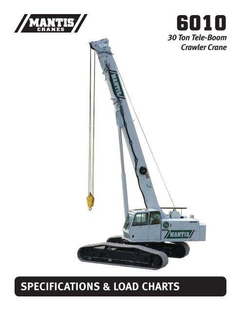
6010<br />
30 Ton Tele-Boom<br />
Crawler Crane
MANTIS2<br />
For over thirty years, Mantis telescopic boom crawler cranes have set the global standard<br />
with the dependability, versatility and performance expected of a market leader. Mantis cranes<br />
are built like no other. At their hearts, are massive steel fabrications, over-sized to handle the<br />
toughest jobs, year-in and year-out. Powerful state-of-the-art hydraulics coupled with diesel<br />
engines available in a choice of sizes match perfectly to meet the most rigorous of project<br />
demands.<br />
Mantis remains one of the few crane makers prepared and equipped to work with contractors<br />
and project engineers to develop customized lifting solutions that meet the most unusual<br />
of project challenges. Thanks to the versatile combination of heavy duty telescopic booms,<br />
hydraulically extendable crawlers, and extremely compact dimensions, Mantis cranes<br />
can often get closer to a job than bulkier, fixed length lattice boom crawler cranes or<br />
rubber-tired cranes that need outriggers to work effectively.<br />
No other crane combines so many valuable features:<br />
• Pick-and-carry the full crane load chart through 360°.<br />
• Lift and walk...even with tracks retracted.<br />
• Climb steeper grades more safely, thanks to minimized counterweight<br />
and low center of gravity.<br />
• Pull through deep mud without bogging down.<br />
• Telescope or lift the boom with a full load on the hook.<br />
• Save time and money on the job due to its low clearance height, retract<br />
on-the-fly tracks and telescopic boom.<br />
• Independent hydrostatic track drive allows pivot turns to run rings around RTs.<br />
• Hydraulic tool circuit option powers wide choice of Mantis-approved tools.<br />
• New luxury cab with state-of-the-art operator aids.<br />
• Saves time and money on deployment and shipping with less haul vehicles,<br />
less time wasted on boom erection and fewer personnel on the erection crew.
6010<br />
3
MANTIS ® 6010<br />
30 TON TELE-BOOM CRAWLER CRANE<br />
With 10-plus years worldwide service behind it, the Mantis<br />
6010 is one of the most performance-proven, bullet-proof<br />
telescopic boom crawler cranes available – anywhere!<br />
This 30-ton (27.2-tonne) capacity crane shares the supercompact<br />
dimensions of its smaller sister, the Mantis 3612.<br />
And like all Mantis cranes, it can pick-and-carry its entire<br />
load chart – through 360°.<br />
Low center of gravity and a wide stance make the 6010 a<br />
favorite where extra lifting capacity and reach are needed.<br />
The 6010 can walk with full boom and jib deployed, or with<br />
full nominal capacity suspended. It can even walk with<br />
30-tons (27.3-tonnes) suspended with full counterweight<br />
removed or tracks retracted when lower ground bearing<br />
pressure or narrower widths are needed.<br />
KEY FEATURES INCLUDE:<br />
ON THE JOB<br />
• 30-tons (27.2-tonnes) pick-and-carry capacity – 360°.<br />
• Fully synchronized three-section full power boom of<br />
80ft (24.4m) length.<br />
• Two-piece swingaway lattice boom extension & offsettable<br />
jib for up to 124ft (37.8m) tip height.<br />
• 173 hp (130kW) diesel engine standard.<br />
• Low ground bearing pressure of 6.6 psi (0.47 kg/cm2).<br />
• Mantis-engineered in-situ auger options with optional<br />
hydraulic tool circuit.<br />
• Fast two-speed independent hydrostatic track drive to<br />
3 mph (4.8 km/hr).<br />
• Full boom telescoping and boom lift under full hook load.<br />
• 8ft 8ins (2.64m) minimum travel width<br />
(with 18ins (457mm) tracks).<br />
• Choice of track shoe widths, Apex swamp pads or bolt-on rubber<br />
track pads to suit any ground surface.<br />
• 61-64,000lb (28-29-tonne) shipping weight fully equipped – hauls<br />
as a single, ready-to-work load.<br />
• Steep 56% gradeability thanks to low centre of gravity.<br />
• Hydraulic on-the-fly track frame retraction and extension.<br />
• 11,000lb (5-tonne) pla<strong>net</strong>ary main winch with full load single line<br />
speeds to 256 fpm (78 mpm).<br />
• High 14ins (358mm) ground clearance helps avoid damage<br />
and snagging.<br />
POWER TRANSMISSION<br />
Whenever possible, electric utility power transmission<br />
grids are planned in straight lines – whether hills,<br />
rocks, ridges or rivers are in their way. For utility<br />
contractors being ready for whatever may lay in the<br />
way means choosing a crane that can cope with<br />
almost any terrain....pick-and-carry towers, drill their<br />
foundations and string the wires.<br />
MISSISSIPPI MUD!<br />
When a job has to cross wide, shallow, water it’s a challenge for any contractor. But these<br />
issues are minimized by employing a crane with very low ground bearing pressure,<br />
fully sealed track gear, high ground clearance and full pick-and-carry capacity.<br />
4
FOUNDATION<br />
Equipped with a special rear-mounted power pack, this 6010 is operating with an auger casting<br />
attachment. The flexibility of the telescoping boom brings versatility to the handling of foundation tools<br />
compared to the limitations of fixed-length lattice booms. Faster travel speeds, lower ground bearing<br />
pressures, compact dimensions and superior gradeability allow the Mantis to go places faster, and<br />
more safely than other types of cranes.<br />
ON THE JOB<br />
WORK PLATFORM<br />
The Mantis 6010 is an ideal machine<br />
for powerline erection and other duties<br />
where crawler-mounting, load lifting<br />
and personnel-handling are combined.<br />
The Mantis WP-750 heavy duty work<br />
platform was designed for the special<br />
needs of Mantis users. With a large<br />
floor area of 6ft x 3ft (1.8m x 0.9m)<br />
and 750lbs (3340kg) capacity the WP-<br />
750 can be installed either on the main<br />
telescopic boom or, as seen here, on<br />
the lattice extension for increased reach<br />
of up to 110ft (33.5m).<br />
EASY HAULER<br />
The 6010 closes down to widths of between 8ft 8ins (2.64m), has 9ft 2ins<br />
(2.8m) clearance height and an overall length of just 41ft 1ins (12.53m). Fully<br />
equipped it scales at anything from 61-64,000lbs (27.8-28.8-tonnes) and in<br />
most cases it can be loaded on a single trailer with no disassembly, in a matter<br />
of minutes and arrives ready to work.<br />
POWER TRANSMISSION<br />
Picking and walking with heavy, bulky and awkward loads like<br />
power towers is a challenge for most cranes and crane operators.<br />
To complete the job safely and efficiently, you need a crane with very<br />
low center of gravity and minimal counterweight to offset backward<br />
tilting moment. When combined with full pick-and-carry capacity,<br />
minimum ground bearing pressure, maximum stability, strong, rigid<br />
structures and fine precision load control the Mantis becomes the<br />
ideal transmission line construction tool. Even special features like<br />
a hydraulic pole clamp and snow shoes for icy inclines!<br />
HIGHWAY CONTRUCTION<br />
Mantis cranes make excellent tools for the vast variety of work involved in highway and bridge<br />
construction. Low clearance height and narrow working widths keep the traffic flowing, full pick-andcarry<br />
capacity and the flexibility of telescopic adjustment of boom length eases the delicate placing of<br />
heavy bridge beams. Low ground bearing pressures means no stops for bad weather or soft ground.<br />
5
<strong>SPECIFICATIONS</strong><br />
MANTIS ® 6010<br />
30 TON TELE-BOOM CRAWLER CRANE<br />
Shoe<br />
Width<br />
18 in<br />
(457 mm)<br />
24 in<br />
(609 mm)<br />
30 in<br />
(762 mm)<br />
WIDTHS, WEIGHTS, AND GROUND PRESSURES*<br />
Retracted<br />
8 ft 6 in<br />
(2.59 m)<br />
9 ft 8 in<br />
(2.95 m)<br />
10 ft 2 in<br />
(3.10 m)<br />
Overall Width<br />
Extended<br />
13 ft 6 in<br />
(4.11 m)<br />
14 ft 0 in<br />
(4.27 m)<br />
14 ft 6 in<br />
(4.42 m)<br />
Area<br />
5,760 in²<br />
(3.72 m²)<br />
7,680 in²<br />
(4.95 m²)<br />
9,600 in²<br />
(6.19 m²)<br />
Ground<br />
Pressure<br />
10.5 psi<br />
(0.74 kg/cm²)<br />
8.0 psi<br />
(0.56 kg/cm²)<br />
6.5 psi<br />
(0.46 kg/cm²)<br />
* Crane equipped with: 80 ft boom, extension, jib, 30 ton hook block, and 7 ton headache ball<br />
Working<br />
Weight<br />
60,505 lb<br />
(27,445 kg)<br />
61,665 lb<br />
(27,971 kg)<br />
62,820 lb<br />
(28,495 kg)<br />
A<br />
B<br />
C<br />
D<br />
E<br />
F<br />
G<br />
H<br />
I<br />
J<br />
K<br />
L<br />
M<br />
N<br />
O<br />
PRINCIPAL DIMENSIONS<br />
Length<br />
(Counterweight Removed)<br />
CL Front Track Drive to CL<br />
Rotation<br />
CL Rear Track Drive to CL<br />
Rotation<br />
Track Length<br />
Boom Length to<br />
CL Rotation<br />
Tailswing<br />
Overall Length<br />
Ground to Top of Engine<br />
Cover<br />
Track Height<br />
Ground Clearance<br />
Ground to Bottom of Cab<br />
Maximum Overall Height<br />
Track Width<br />
Overall Width<br />
(Tracks Retracted)<br />
Overall Working Width<br />
40 ft 2 in<br />
(12.24 m)<br />
80 in<br />
(2.03 m)<br />
81 in<br />
(2.06 m)<br />
16 ft 1 in<br />
(4.90 m)<br />
28 ft 6 in<br />
(8.69 m)<br />
12 ft 8 in<br />
(3.86 m)<br />
41 ft 1 in<br />
(12.52 m)<br />
90 in<br />
(2.29 m)<br />
42 in<br />
(1.07 m)<br />
11 in<br />
(279 mm)<br />
46 in<br />
(1.17 m)<br />
9 ft 6 in<br />
( 2.90 m)<br />
30 in<br />
(762 mm)<br />
10 ft 2 in<br />
(3.10 m)<br />
14 ft 6 in<br />
(4.42 m)<br />
6
<strong>SPECIFICATIONS</strong><br />
MANTIS ® 6010<br />
30 TON TELE-BOOM CRAWLER CRANE<br />
STANDARD CRANE AND EQUIPMENT<br />
Boom<br />
The boom consists of three full power sections. Retracted length is 32 ft<br />
8 in (9.96 m) and extended length is 80 ft (24.38 m). Maximum tip height<br />
is 85 ft (25.91 m).<br />
Boom Telescoping & Elevating Systems<br />
The elevating system features a single cylinder and counterbalance lock<br />
valves which provides boom elevations from -1° to 78°.<br />
The telescoping system features a single double-acting hydraulic cylinder<br />
and counterbalance lock valves.<br />
Boom Head<br />
Five 15 in (381 mm) diameter cast nylon sheaves on heavy-duty roller<br />
bearings are mounted in the boom head.<br />
Load Moment Indicator & Anti-Two Block 1<br />
SUPERSTRUCTURE<br />
Frame<br />
The frame is an all-steel, welded structure, precision machined to accept<br />
attachment of the boom and swing components.<br />
Operator’s Cab<br />
The fully-enclosed, air conditioned all-steel modular cab includes a<br />
lockable swinging door, acoustical lining, anti-slip floor and tinted safety<br />
glass. Sliding windows are located in the cab door and cab boom side.<br />
A vent window is positioned in the rear of the cab. Grab bars and steps<br />
are appropriately located for easy access to the cab. Erectable swing<br />
barricades are attached to the superstructure. Rear view cameras are<br />
appropriately located as are work lights.<br />
Standard cab accessories include a two-speed windshield wiper, top<br />
glass wiper, defroster, heater, circulating fan, adjustable hand and foot<br />
throttles, six-way adjustable fabric seat with headrest, seat belt, dome<br />
light, and a dry-chemical fire extinguisher.<br />
Instrumentation<br />
Dash instrumentation features a tachometer, voltmeter, oil pressure<br />
gauge, temperature gauge, hour meter and fuel gauge. Indicators are<br />
provided for crane level, load moment, drum rotation, air filter restriction,<br />
hydraulic oil temperature and filter restriction, engine oil pressure and<br />
temperature.<br />
A termination switch is located in the seat and armrest and is capable of<br />
immediately disabling all hydraulic functions as the operator rises from<br />
the seat or it can be activated by lifting the left hand armrest.<br />
Control<br />
Two-way hydraulic joysticks mounted in the armrests of the operator’s<br />
seat control swing, boom extend, main winch and boom hoist. Three<br />
two-way hydraulic foot pedals control the travel and swing service brake<br />
functions. Travel pedal hand levers are available as an option. A fourth<br />
pedal controls engine speed.<br />
Counterweight<br />
The 11,500 lb (5,220 kg) single piece counterweight can be removed and<br />
installed via a pendant attached to the boom.<br />
Standard Rated Capacity Limiter and Anti-Two Block system includes<br />
audio and video warnings and control function shutdown. System’s LCD<br />
screen provides a continuous electronic display of working boom length,<br />
boom angle, working load radius, tip height, parts-of-line (operator set),<br />
machine track configuration, relative load moment, maximum permissible<br />
load and actual load. The standard Work Area Definition audio and<br />
video warnings aid the operator in avoiding job-site obstructions by<br />
pre-setting and defining the work area. The anti-two block weight allows<br />
quick reeving of hook blocks.<br />
Swing<br />
The superstructure rotates 360° on an external gear shear ball slew<br />
bearing bolted to the superstructure and the carbody. The hydraulic<br />
swing drive powers the system and consists of a gear motor driving a<br />
pla<strong>net</strong>ary gear reducer with a shaft mounted pinion, providing infinitely<br />
variable speeds of up to 3 rpm.<br />
Swing braking is achieved through a “failsafe”, hydraulically released,<br />
spring applied, multi-disc brake which includes a foot applied service<br />
brake. Alternatively, the brake can be electrically actuated through a cab<br />
mounted switch into a “locked-on” (parking) mode. A two position house<br />
lock system is included. Regular lubrication of the bearing is achieved<br />
through a cab mounted grease applicator.<br />
Fuel System<br />
An 80 US gal (303 liter) tank is bolted to the superstructure. The fuel<br />
filtration system consists of an inline fuel/water separator as well as an<br />
engine mounted fuel filter.<br />
Hydraulic System<br />
The load sensing, open-loop hydraulic system is served by two variable<br />
volume pumps mounted in tandem. The pumps are torque limiting and<br />
pressure compensated providing a maximum output of 115 gpm (437<br />
l/min) @ 2,200 rpm and maximum operating pressure of 4,850 psi (339.5<br />
kg/cm²). An extra circuit is included for ready adaptation to hydraulic<br />
accessories.<br />
The system includes two pilot operated valve banks that are pressure<br />
and flow compensated. The 150 US gal (568 liter) capacity hydraulic oil<br />
reservoir has a spin-on filler-breather cap, external sight gauge, cleanout<br />
access and a sump type drain. Hydraulic oil filtering is achieved with<br />
two 5 micron full flow cartridge type filters designed to return in-tank with<br />
bypass protection and an electronic bypass indicator.<br />
(System pressure test ports with quick disconnect fittings are provided<br />
for diagnostic purposes.)<br />
7
<strong>SPECIFICATIONS</strong><br />
MANTIS ® 6010<br />
30 TON TELE-BOOM CRAWLER CRANE<br />
MAIN HOIST<br />
Pla<strong>net</strong>ary geared single-speed winch includes a bent axis, variable displacement hydraulic motor and a multi-disc internal brake. Wire Rope: 600 ft (183 m) 9/16 in (14 mm) 6 x 37<br />
EIPS, IWRC, RRL. Line pulls are not based on wire rope strength. Drum rotation indicator is standard.<br />
Rope<br />
Layer<br />
Rope<br />
Layer<br />
Maximum Line Pull Full Load Line Speed Pitch Diameter Layer Total<br />
1 11,000 lb 4,990 kg 198 ft/min 60.4 m/min 11.2 in 284.3 mm 70 ft 21.4 m 70 ft 21.4 m<br />
2 10,000 lb 4,540 kg 212 ft/min 64.6 m/min 12.2 in 309.1 mm 76 ft 23.3 m 147 ft 44.7 m<br />
3 9,100 lb 4,130 kg 221 ft/min 67.4 m/min 13.1 in 333.9 mm 83 ft 25.2 m 229 ft 69.9 m<br />
4 8,400 lb 3,810 kg 229 ft/min 69.8 m/min 14.1 in 358.8 mm 89 ft 27.1 m 318 ft 97.0 m<br />
5 7,800 lb 3,540 kg 244 ft/min 74.4 m/min 15.1 in 383.6 mm 95 ft 28.9 m 413 ft 125.9 m<br />
6 7,300 lb 3,310 kg 247 ft/min 75.3 m/min 16.1 in 408.4 mm 101 ft 30.8 m 514 ft 156.7 m<br />
7 6,800 lb 3,080 kg 256 ft/min 78.0 m/min 17.1 in 433.2 mm 107 ft 32.7 m 621 ft 189.4 m<br />
AUXILIARY HOIST<br />
Pla<strong>net</strong>ary geared single-speed winch includes a bent axis, variable displacement hydraulic motor and a multi-disc internal brake.<br />
Wire Rope: 300 ft (91 m) 9/16 in (14 mm) 6 x 37 EIPS, IWRC, RRL Line pulls are not based on wire rope strength. Drum rotation indicator is standard.<br />
Maximum Line Pull Full Load Line Speed Pitch Diameter Layer Total<br />
1 12,000 lb 5,440 kg 182 ft/min 55.5 m/min 10.3 in 261.9 mm 66 ft 20.1 m 66 ft 20.1 m<br />
2 10,800 lb 4,900 kg 198 ft/min 60.4 m/min 11.3 in 286.8 mm 72 ft 22.0 m 138 ft 42.1 m<br />
3 9,800 lb 4,450 kg 205 ft/min 62.5 m/min 12.3 in 311.6 mm 79 ft 23.9 m 217 ft 66.1 m<br />
4 9,000 lb 4,080 kg 214 ft/min 65.2 m/min 13.2 in 336.4 mm 85 ft 25.8 m 302 ft 91.9 m<br />
5 8,300 lb 3,760 kg 228 ft/min 69.5 m/min 14.2 in 361.2 mm 91 ft 27.7 m 393 ft 119.6 m<br />
STANDARD ENGINE<br />
Cummins QSB173 (U.S. EPA Tier 3)<br />
Noise Emissions: Top 96.3 dBa (excludes noise from intake, exhaust, cooling system and driven components)<br />
Type 6 Cylinder Water Cooled Weight (Wet) 1005 lb (457 kg) Aspiration Turbocharged & Aftercooled<br />
Displacement 359 cu in (5.9 l) Oil Capacity 17.2 US quarts (16.3 l) Air Filter Dry Type<br />
Bore 4.02 in (102 mm) Rated Horsepower 173 @ 2200 rpm Electrical System 12 volt<br />
Stroke 4.72 in (120 mm) Peak Torque 590 ft/lb @ 1500 rpm Alternator 100 amp<br />
STANDARD CRANE WITH 3 SECTION 80 ft 0 in (24.38 m) BOOM,<br />
1 PIECE COUNTERWEIGHT & 30 in (762 mm) TRACK SHOES<br />
MACHINE WEIGHTS<br />
59,980 lb 27,210 kg<br />
Crane Less Counterweight 48,480 lb 21,990 kg<br />
Counterweight 11,500 lb 5,220 kg<br />
OPTIONAL EQUIPMENT<br />
20 ft (6.10 m) Lattice Extension 1,200 lb 544 kg<br />
20 ft (6.10 m) Jib (connects to head of Lattice Extension ONLY) 700 lb 318 kg<br />
Auxiliary Nose Sheave 150 lb 68 kg<br />
Auxiliary Winch with Standard Rope 607 lb 275 kg<br />
12 ton (11 mt) Headache Ball 180 lb 82 kg<br />
30 ton (27 mt) Hook Block 760 lb 345 kg<br />
Auger Ready Package 440 lb 200 kg<br />
Complete Auger Package 1,520 lb 690 kg<br />
60 in (1.52 m) Auger Kelly Bar 120 lb 54 kg<br />
72 in (1.83 m) Auger Kelly Bar 140 lb 64 kg<br />
72 in (1.83 m) Auger kelly bar 140 lb 64 kg<br />
* Deduction from Standard Crane Weight<br />
8
<strong>SPECIFICATIONS</strong><br />
MANTIS ® 6010<br />
30 TON TELE-BOOM CRAWLER CRANE<br />
UNDERCARRIAGE<br />
Carbody<br />
The steel box type carbody is fabricated with square axles to accept the<br />
crawler side frames. The top surface is precision machined to receive the<br />
swing bearing.<br />
Side Frames<br />
Two welded steel side frames are paired with a track group consisting<br />
of nine sealed rollers located on the bottom of the frame. Each frame<br />
includes a self-lubricating idler and spring type track tensioning device.<br />
Standard track shoes are 30 in (762 mm) wide, 3-bar semi-grousers.<br />
Optional shoes are available in 18 in (457 mm) and 24 in (609 mm)<br />
widths in both flat pad and semi-grouser configurations. Flat pads are<br />
also available in 30 in widths. The side frames extend and retract<br />
hydraulically and are controlled from the cab.<br />
Travel<br />
Each side frame contains a pilot controlled, two-speed track drive. The<br />
drives are hydraulic piston motors which propel the crane at a low speed<br />
of 2.0 mph (3.2 km/hr) and at a high speed of 3.0 mph (4.8 km/hr). The<br />
internal brake system is spring applied and automatically released upon<br />
actuation of the travel system.<br />
The hydraulic travel system provides skid steering and track counter<br />
rotation and achieves an unladen gradeability of 56%.<br />
OPTIONAL EQUIPMENT<br />
Boom Attachments<br />
• Boom Extension: 20 ft (6.10 m), lattice type swingaway that stores<br />
alongside of the boom base section and can be used with or without<br />
the optional 20 ft (6.10 m) jib. Head contains two 19 in (483 mm)<br />
diameter high strength cast nylon sheaves mounted on heavy-duty<br />
roller bearings, reeving up to 2 parts of wire rope. With optional<br />
extension deployed maximum tip height is 102 ft (31.09 m).<br />
• Boom Jib: 20 ft (6.10 m) lattice type swingaway, attaches to and<br />
stores alongside the extension and can only be used with the extension<br />
deployed. Offsets are at 15° & 30°. With jib and extension deployed<br />
maximum tip height is 124 ft (37.80 m).<br />
• Auxiliary Nose Sheave: quick reeve, single 15 in (381 mm) diameter<br />
high-strength, cast nylon sheave mounted on a heavy-duty roller<br />
bearing.<br />
• Wire Rope: rotation resistant, (non-spin) Dyform-18 HSLR.<br />
• Headache Ball: 7 ton (11 mt) ball includes a swivel hook with a safety<br />
latch.<br />
• Hook Block: 37 ton (27 mt) hook block contains three 16 in (406 mm)<br />
diameter sheaves mounted on heavy-duty roller bearings with a swivel<br />
hook and safety latch.<br />
Hydraulic<br />
• Auger Ready Package: includes hoses, fasteners and stowage<br />
bracket assembly mounted to the base section of the boom with a flow<br />
capability of 34 gpm (130 l/min).<br />
• Complete Auger Package: adds a two speed auger motor/gear box<br />
and one 60 in (1.52 m) kelly bar to the Auger Ready Package.<br />
• Tool Circuit: provides 6 gpm (23 l/min) and 12 gpm (45 l/min) at 2,500<br />
psi (176 kg/cm²) through a 50 ft (15.24 m) twin hose reel with quick<br />
disconnect fittings to operate open center tools.<br />
Other Options<br />
• Free Fall Hoists: all winches are available in free fall and controlled<br />
free fall configurations.<br />
• Crane Cab Access Walkway: a pair of 54.5 in (1.38 m) wide x 25 in<br />
(635 mm) deep walkways which attach to both the front and rear of the<br />
carbody and allow for easier egress and ingress to the operator’s cab<br />
when the crane’s upper rotating frame is not aligned front to rear.<br />
• Model WP750 Work Platform: 36 in x 72 in (914 mm x 1 828 mm),<br />
all-steel, two-person platform with a maximum capacity of 750 lb<br />
(340 kg). A test weight and boom head adapter are included in the<br />
package. Operation and control are by the crane operator from the cab.<br />
Radio (RF) controls to enable remote operation from the platform are<br />
available.<br />
(See separate WP750 Specification for a complete description of standard and<br />
optional Work Platform equipment.)<br />
1<br />
Load moment indicating and anti-two block systems are operator aids and must never be used in lieu of job site lift planning calculations by the operator which must take into account ground conditions, weather and all other environmental factors prevailing at the time of the lift. Prices<br />
and specifications are subject to change at any time without prior notice and are for factory installation at time of original manufacture. F.O.B Plant; Richlands, VA 24641. Illustrations and photographs may show optional equipment. Supercedes all previous issues. Please see www.<br />
mantiscranes.com for most current information.<br />
9
<strong>LOAD</strong> <strong>CHARTS</strong><br />
MANTIS ® 6010<br />
30 TON TELE-BOOM CRAWLER CRANE<br />
80 FT MAIN BOOM, 20 FT EXTENSION & 20 FT JIB<br />
60 in<br />
(1.5 m)<br />
60 in<br />
(1.5 m)<br />
60 in<br />
(1.5 m)<br />
60 in<br />
(1.5 m)<br />
CAUTION<br />
THESE CHART VALUES ARE ONLY A GUIDE AND MUST NOT BE USED TO OPERATE THE CRANE. USE ONLY THE IN CAB <strong>LOAD</strong> <strong>CHARTS</strong> AND OPERATOR’S MANUAL FURNISHED WITH THE CRANE. 10
<strong>LOAD</strong> <strong>CHARTS</strong><br />
MANTIS ® 6010<br />
30 TON TELE-BOOM CRAWLER CRANE<br />
LIFTING CAPACITIES<br />
IN THOUSANDS OF POUNDS; 360°, 75% OF TIPPING, FIRM & LEVEL GROUND<br />
MAIN BOOM with TRACKS FULLY EXTENDED<br />
11,500 lb COUNTERWEIGHT ZERO COUNTERWEIGHT<br />
RADIUS<br />
(ft)<br />
8<br />
10<br />
12<br />
15<br />
20<br />
25<br />
30<br />
35<br />
40<br />
45<br />
50<br />
55<br />
60<br />
65<br />
70<br />
75<br />
MAIN BOOM LENGTH (ft)<br />
MAIN BOOM LENGTH (ft)<br />
33.0 41.0 48.0 56.0 64.0 72.0 80.0 33.0 41.0 48.0 56.0 64.0 72.0 80.0<br />
60.0 48.0 47.6* 60.0 48.0 47.6*<br />
71.8° 75.5° 77.9° 71.8° 75.5° 77.9°<br />
60.0 48.0 47.6 44.9* 53.0 48.0 47.6 44.9*<br />
67.9° 72.5° 75.5° 77.6° 67.9° 72.5° 75.5° 77.6°<br />
56.0 48.0 47.6 40.5 34.2* 35.4 35.7 35.9 36.0 34.2*<br />
63.9° 69.4° 73.0° 75.4° 77.3° 63.9° 69.4° 73.0° 75.4° 77.3°<br />
38.5 38.7 38.9 35.4 29.8 26.0 22.8* 23.0 25.3 23.5 23.6 23.6 23.7 22.8*<br />
57.5° 64.7° 69.1° 72.2° 74.5° 76.2° 77.6° 57.5° 64.7° 69.1° 72.2° 74.5° 76.2° 77.6°<br />
24.0 24.2 24.3 24.4 24.0 21.3 18.7 13.9 14.1 14.2 14.3 14.4 14.4 14.5<br />
45.5° 56.2° 62.5° 66.7° 69.7° 72.1° 73.9° 45.5° 56.2° 62.5° 66.7° 69.7° 72.1° 73.9°<br />
16.9 17.2 17.3 17.3 17.4 17.0 15.8 9.4 9.6 9.8 9.9 9.9 10.0 10.0<br />
29.0° 46.6° 55.3° 60.8° 64.8° 67.8° 70.1° 29.0° 46.6° 55.3° 60.8° 64.8° 67.8° 70.1°<br />
13.0 13.1 13.2 13.2 13.3 13.0 7.0 7.1 7.2 7.3 7.3 7.3<br />
34.7° 47.3° 54.6° 59.6° 63.3° 66.2° 34.7° 47.3° 54.6° 59.6° 63.3° 66.2°<br />
10.2 10.3 10.4 10.5 10.5 10.5 5.2 5.4 5.5 5.5 5.6 5.6<br />
14.5° 38.0° 47.8° 54.1° 58.7° 62.1° 14.5° 38.0° 47.8° 54.1° 58.7° 62.1°<br />
8.4 8.5 8.5 8.5 8.6 4.1 4.2 4.3 4.3 4.4<br />
25.5° 40.1° 48.2° 53.8° 57.9° 25.5° 40.1° 48.2° 53.8° 57.9°<br />
7.0 7.1 7.1 7.1 3.3 3.4 3.4 3.4<br />
30.6° 41.6° 48.5° 53.4° 30.6° 41.6° 48.5° 53.4°<br />
5.9 5.9 6.0 6.0 2.6 2.7 2.7 2.7<br />
15.8° 33.8° 42.7° 48.7° 15.8° 33.8° 42.7° 48.7°<br />
5.0 5.1 5.1 2.1 2.1 2.1<br />
23.7° 36.1° 43.5° 23.7° 36.1° 43.5°<br />
4.3 4.4 1.6 1.7<br />
28.1° 37.8° 28.1° 37.8°<br />
3.7 3.7 1.3 1.3<br />
16.4° 31.1° 16.4° 31.1°<br />
3.2 1.0<br />
22.6° 22.6°<br />
2.8 0.7<br />
4.2° 4.2°<br />
RADIUS<br />
(ft)<br />
8<br />
10<br />
12<br />
15<br />
20<br />
25<br />
30<br />
35<br />
40<br />
45<br />
50<br />
55<br />
60<br />
65<br />
70<br />
75<br />
* Capacity based on maximum obtainable boom angle.<br />
° Boom angles are stated in degrees.<br />
CAUTION<br />
THESE CHART VALUES ARE ONLY A GUIDE AND MUST NOT BE USED TO OPERATE THE CRANE. USE ONLY THE IN CAB <strong>LOAD</strong> <strong>CHARTS</strong> AND OPERATOR’S MANUAL FURNISHED WITH THE CRANE. 11
<strong>LOAD</strong> <strong>CHARTS</strong><br />
MANTIS ® 6010<br />
30 TON TELE-BOOM CRAWLER CRANE<br />
LIFTING CAPACITIES<br />
IN THOUSANDS OF POUNDS; 360°, 75% OF TIPPING, FIRM & LEVEL GROUND<br />
MAIN BOOM with<br />
TRACKS FULLY RETRACTED<br />
RADIUS (ft)<br />
11,500 lb COUNTERWEIGHT<br />
MAIN BOOM LENGTH<br />
(ft)<br />
33.0 Over 33<br />
RADIUS (ft)<br />
8 60.0 47.6 8<br />
10 49.6 44.9 10<br />
12 36.3 34.2 12<br />
14 25.9 25.9 14<br />
16 21.6 21.6 16<br />
18 17.9 17.9 18<br />
20 15.0 15.0 20<br />
22 12.7 12.7 22<br />
24 11.0 11.0 24<br />
26 9.6 9.6 26<br />
28 8.5 8.5 28<br />
30 7.7 7.7 30<br />
32 7.0 7.0 32<br />
34 6.3 6.3 34<br />
36 5.8 5.8 36<br />
38 5.4 5.4 38<br />
40 5.0 5.0 40<br />
42 4.6 4.6 42<br />
44 4.3 4.3 44<br />
46 4.0 4.0 46<br />
48 3.7 3.7 48<br />
50 3.4 3.4 50<br />
52 3.2 3.2 52<br />
54 2.9 2.9 54<br />
56 2.7 2.7 56<br />
58 2.5 2.5 58<br />
60 2.3 2.3 60<br />
62 2.1 2.1 62<br />
64 1.9 1.9 64<br />
66 1.7 1.7 66<br />
68 1.6 1.6 68<br />
70 1.4 1.4 70<br />
Boom<br />
Angle<br />
20’ EXTENSION & 20’ JIB<br />
with TRACKS FULLY EXTENDED<br />
11,500 lb COUNTERWEIGHT<br />
20’ EXTENSION 20’ JIB<br />
Total Boom Length (ft)<br />
53.0 to<br />
91.9<br />
Jib Offset Angles<br />
92.0 to ? 0° 15° 30°<br />
Boom<br />
Angle<br />
78º 12.4 12.4 6.6 4.0 2.2 78º<br />
75º 10.5 10.5 6.3 4.0 2.1 75º<br />
72º 9.3 9.3 5.6 3.5 2.0 72º<br />
70º 8.6 8.6 5.1 3.2 1.9 70º<br />
68º 8.0 8.0 4.6 3.0 1.8 68º<br />
65º 7.2 6.8 4.2 2.8 1.8 65º<br />
62º 6.6 5.7 3.9 2.6 1.7 62º<br />
60º 6.2 4.9 3.5 2.4 1.7 60º<br />
58º 5.9 4.3 3.2 1.9 1.4 58º<br />
55º 5.5 3.7 2.6 1.3 1.0 55º<br />
52º 5.2 3.2 2.0 0.6 0.4 52º<br />
50º 5.0 2.9 1.5 0.3 0.2 50º<br />
48º 4.4 2.6 48º<br />
45º 4.2 2.3 45º<br />
ZERO DEGREE BOOM ANGLE<br />
MAXIMUM CAPACITY<br />
with TRACKS FULLY EXTENDED<br />
BOOM<br />
LENGTH (ft)<br />
11,500 lb COUNTERWEIGHT<br />
RADIUS<br />
(ft)<br />
<strong>LOAD</strong> (lbs)<br />
(x 1000)<br />
BOOM<br />
LENGTH<br />
(ft)<br />
32.7 27.7 15.4 32.7<br />
40.6 35.6 10.0 40.6<br />
48.4 43.4 7.7 48.4<br />
56.3 51.3 5.7 56.3<br />
64.3 59.2 4.6 64.3<br />
71.1 67.1 3.5 71.1<br />
80.0 75.0 2.8 80.0<br />
WEIGHT REDUCTIONS<br />
<strong>LOAD</strong> HANDLING DEVICES<br />
HOOKBLOCK: 30 Ton - 3 Sheave<br />
OVERHAUL BALL: 12 Ton w/Swivel<br />
OPTIONAL HANDLING DEVICES<br />
** Reduction of main boom capacities.<br />
760 lbs<br />
162 lbs<br />
20 ft. Extension - Stowed** 320 lbs<br />
20 ft. Extension - Erected** 1,600 lbs<br />
20 ft. Ext. and 20 ft. Jib - Stowed** 450 lbs<br />
20 ft. Ext. and 20 ft. Jib - Erected** 3,100 lbs<br />
Auxillary Nose Sheave**<br />
160 lbs<br />
CAUTION<br />
THESE CHART VALUES ARE ONLY A GUIDE AND MUST NOT BE USED TO OPERATE THE CRANE. USE ONLY THE IN CAB <strong>LOAD</strong> <strong>CHARTS</strong> AND OPERATOR’S MANUAL FURNISHED WITH THE CRANE. 12
<strong>LOAD</strong> <strong>CHARTS</strong><br />
MANTIS ® 6010<br />
30 TON TELE-BOOM CRAWLER CRANE<br />
LIFTING CAPACITIES<br />
IN THOUSANDS OF POUNDS; 360°, 75% OF TIPPING, FIRM & LEVEL GROUND<br />
RADIUS<br />
(ft)<br />
8<br />
10<br />
12<br />
15<br />
20<br />
25<br />
30<br />
35<br />
40<br />
45<br />
50<br />
55<br />
60<br />
65<br />
70<br />
75<br />
AUXILIARY NOSE SHEAVE with TRACKS FULLY EXTENDED<br />
11,500 lb COUNTERWEIGHT ZERO COUNTERWEIGHT<br />
MAIN BOOM LENGTH (ft) MAIN BOOM LENGTH (ft) RADIUS<br />
(ft)<br />
33.0 41.0 48.0 56.0 64.0 72.0 80.0 33.0 41.0 48.0 56.0 64.0 72.0 80.0<br />
6.0 6.0 6.0 6.0 6.0 6.0<br />
71.8° 75.5° 77.9° 71.8° 75.5° 77.9°<br />
6.0 6.0 6.0 6.0 6.0 6.0 6.0 6.0<br />
67.9° 72.5° 75.5° 77.6° 67.9° 72.5° 75.5° 77.6°<br />
6.0 6.0 6.0 6.0 6.0 6.0 6.0 6.0 6.0 6.0<br />
63.9° 69.4° 73.0° 75.4° 77.3° 63.9° 69.4° 73.0° 75.4° 77.3°<br />
6.0 6.0 6.0 6.0 6.0 6.0 6.0 6.0 6.0 6.0 6.0 6.0 6.0 6.0<br />
57.5° 64.7° 69.1° 72.2° 74.5° 76.2° 77.6° 57.5° 64.7° 69.1° 72.2° 74.5° 76.2° 77.6°<br />
6.0 6.0 6.0 6.0 6.0 6.0 6.0 6.0 6.0 6.0 6.0 6.0 6.0 6.0<br />
45.5° 56.2° 62.5° 66.7° 69.7° 72.1° 73.9° 45.5° 56.2° 62.5° 66.7° 69.7° 72.1° 73.9°<br />
6.0 6.0 6.0 6.0 6.0 6.0 6.0 6.0 6.0 6.0 6.0 6.0 6.0 6.0<br />
29.0° 46.6° 55.3° 60.8° 64.8° 67.8° 70.1° 29.0° 46.6° 55.3° 60.8° 64.8° 67.8° 70.1°<br />
6.0 6.0 6.0 6.0 6.0 6.0 6.0 6.0 6.0 6.0 6.0 6.0<br />
34.7° 47.3° 54.6° 59.6° 63.3° 66.2° 34.7° 47.3° 54.6° 59.6° 63.3° 66.2°<br />
6.0 6.0 6.0 6.0 6.0 6.0 5.2 5.4 5.5 5.5 5.6 5.6<br />
14.5° 38.0° 47.8° 54.1° 58.7° 62.1° 14.5° 38.0° 47.8° 54.1° 58.7° 62.1°<br />
6.0 6.0 6.0 6.0 6.0 4.1 4.2 4.3 4.3 4.4<br />
25.5° 40.1° 48.2° 53.8° 57.9° 25.5° 40.1° 48.2° 53.8° 57.9°<br />
6.0 6.0 6.0 6.0 3.3 3.4 3.4 3.4<br />
30.6° 41.6° 48.5° 53.4° 30.6° 41.6° 48.5° 53.4°<br />
5.4 5.5 6.0 6.0 2.6 2.7 2.7 2.7<br />
15.8° 33.8° 42.7° 48.7° 15.8° 33.8° 42.7° 48.7°<br />
4.6 4.7 4.7 2.1 2.1 2.1<br />
23.7° 36.1° 43.5° 23.7° 36.1° 43.5°<br />
4.0 4.0 1.6 1.7<br />
28.1° 37.8° 28.1° 37.8°<br />
3.4 3.4 1.3 1.3<br />
16.4° 31.1° 16.4° 31.1°<br />
2.9 1.0<br />
22.6° 22.6°<br />
2.5 0.7<br />
4.2° 4.2°<br />
8<br />
10<br />
12<br />
15<br />
20<br />
25<br />
30<br />
35<br />
40<br />
45<br />
50<br />
55<br />
60<br />
65<br />
70<br />
75<br />
° Boom angles are stated in degrees.<br />
CAUTION<br />
THESE CHART VALUES ARE ONLY A GUIDE AND MUST NOT BE USED TO OPERATE THE CRANE. USE ONLY THE IN CAB <strong>LOAD</strong> <strong>CHARTS</strong> AND OPERATOR’S MANUAL FURNISHED WITH THE CRANE.<br />
13
MANTIS ® 6010<br />
30 TON TELE-BOOM CRAWLER CRANE<br />
<strong>LOAD</strong> <strong>CHARTS</strong><br />
MANTIS WP-750 WORK PLATFORM<br />
Limits of operation: Maximum load capacity = 750 lb<br />
Maximum radius when mounted on main boom = 68 ft<br />
CAUTION<br />
THESE CHART VALUES ARE ONLY A GUIDE AND MUST NOT BE USED TO OPERATE THE CRANE. USE ONLY THE IN CAB <strong>LOAD</strong> <strong>CHARTS</strong> AND OPERATOR’S MANUAL FURNISHED WITH THE CRANE.<br />
14
<strong>LOAD</strong> <strong>CHARTS</strong><br />
MANTIS ® 6010<br />
30 TON TELE-BOOM CRAWLER CRANE<br />
MANTIS MODEL 6010<br />
WIRE ROPE LINE PULL CAPACITIES<br />
PARTS<br />
OF LINE<br />
MAIN WINCH<br />
(pounds)<br />
AUX WINCH<br />
(pounds)<br />
PARTS<br />
OF LINE<br />
MAIN WINCH<br />
(pounds)<br />
1 9,600 9,600 5 48,000<br />
2 19,200 19,200 6 57,600<br />
3 28,800 N/A 7 67,200<br />
4 38,400 N/A<br />
9/16 inch diameter wire rope, 6 x 37 Class, EIP, IWRC<br />
PLEASE READ, UNDERSTAND, AND FOLLOW THE MANUALS FURNISHED WITH THE CRANE (OPERATOR’S AND SAFETY)<br />
AS WELL AS THE CAPACITY LIMITATIONS AND GENERAL CONDITIONS LISTED BELOW PRIOR TO OPERATION OF THE CRANE.<br />
FAILURE TO DO SO MAY RESULT IN AN ACCIDENT.<br />
Capacity Limitations and General Conditions:<br />
1. This MANTIS CRANE as manufactured, meets the requirements of<br />
ANSI B30.5 (2000). Structure and stability have been tested in accordance<br />
with SAE J1063 and SAE J765, respectively. Modifications<br />
to the crane or use of optional equipment other than specified by the<br />
manufacturer can result in a reduction of capacity.<br />
2. The main boom and auxliary boom head lifting capacities are determined<br />
by boom length and load radius. The extension and jib lifting<br />
capacities are determined by boom angle.<br />
3. Rated capacity loads given are maximum covered by the manufacturer’s<br />
warranty and are based on a freely suspended load with NO<br />
allowance for factors such as out-of-level operation, supporting surface<br />
conditions, hazardous surroundings, experience of personnel,<br />
etc. The operator shall establish practical working loads based on<br />
prevailing operating conditions, such as, but not limited to the above.<br />
4. All rated capacity loads shown apply to original equipment as supplied<br />
by SpanDeck, Inc.<br />
5. All rated capacity loads appearing above the bold line are based on<br />
structural strength; tipping should not be relied upon as a capacity<br />
limitation.<br />
6. All rated capacity loads appearing below the bold line are based on<br />
stability and do not exceed 75% of tipping.<br />
7. Deductions from rated capacities must be made for the weight of<br />
the hook block, headache ball, slings, spreader bar, and any other<br />
suspended equipment. See Lifting Capacity Deduction Chart for load<br />
handling devices supplied by SpanDeck, Inc.<br />
8. A properly calibrated and maintained Load Moment Indicator (LMI)<br />
system will indicate boom mounted and other suspended equipment.<br />
9. When making lifts where capacities may be within a zone limited by<br />
structural strength, the operator shall determine that the weight of<br />
the load is known within plus or minus (+/-) ten percent (10%) before<br />
making lift.<br />
10. It is permissible to attempt to telescope boom with a load within the<br />
limits of rated capacities. However, boom telescope system hydraulic<br />
pressure, and/or boom lubrication may affect operation.<br />
11. Side pull on boom is extremely dangerous and must be avoided.<br />
12. DO NOT exceed manufacturers maximum specified reeving.<br />
13. DO NOT lift load or extend boom without proper configuration of<br />
crane per load chart selected.<br />
14. DO NOT attempt to lift any load when wind speed exceeds 20 mph.<br />
Load moment indicating and anti-two block systems are operator aids and must never be used in lieu of job site lift planning calculations by the<br />
operator which must take into account ground conditions, weather and all other environmental factors prevailing at the time of the lift.<br />
Prices and specifications are subject to change at any time without prior notice and are for factory installation at the time of original manufacture.<br />
F.O.B Plant; Richlands, VA 24641. Illustrations and photographs may show optional equipment. Supercedes all previous issues.<br />
Please see www.mantiscranes.com for most current information.<br />
CAUTION<br />
THESE CHART VALUES ARE ONLY A GUIDE AND MUST NOT BE USED TO OPERATE THE CRANE. USE ONLY THE IN CAB <strong>LOAD</strong> <strong>CHARTS</strong> AND OPERATOR’S MANUAL FURNISHED WITH THE CRANE.<br />
15