option TPS 7.1.2.2 - Inele
option TPS 7.1.2.2 - Inele
option TPS 7.1.2.2 - Inele

You also want an ePaper? Increase the reach of your titles
YUMPU automatically turns print PDFs into web optimized ePapers that Google loves.
Technik<br />
568 962<br />
MTS 7.1.2.1<br />
Fundamentals of<br />
ISDN Technology
MTS 7.1.2.1<br />
Fundamentals of<br />
ISDN Technology<br />
by<br />
Maria Spath<br />
and Reinhard Heermeyer
“The sensitive electronics of the equipment contained in the present experiment literature<br />
can be impaired due to the discharge of static electricity. Consequently, electrostatic<br />
build up should be avoided (particularly by utilizing appropriate rooms) or<br />
eliminated by discharging (e.g. at the panel frames or similar).”<br />
User's note<br />
The ISDN technology training system uses commercially available ISDN equipment. This requires<br />
that the following principles be adhered to by the student and instructor:<br />
• The digital exchange contained in the training system is equipped solely for training purposes. Any<br />
connection to public or internal ISDN networks is totally out of the question. Leybold Didactic can<br />
under no circumstances assume liability for disturbances arising from a violation of this limitation<br />
to utilization.<br />
• Leybold Didactic can under no circumstances guaranty operation for any foreign devices<br />
connected to this digital exchange.<br />
• Should there be any differences between the experiment descriptions and the user's instructions for<br />
the ISDN equipment the manufacturer's manuals take precedence.<br />
• The experiments described in this manual constitute a representative selection of important topics,<br />
which by no means exhaust the performance spectrum of terminal equipment and digital<br />
exchange. Some experiments not included in the descriptions are thus possible but are not dealt<br />
with by the Leybold Didactic training system.
MTS 7.1.2.1 Fundamentals of ISDN Technology Contents<br />
Theory<br />
Table of Contents<br />
Equipment overview ..................................................................................................7<br />
1 The basics of Euro-ISDN ...............................................................................8<br />
1.1 Historical development ....................................................................................................... 8<br />
1.2 Connection <strong>option</strong>s ............................................................................................................. 9<br />
1.2.1 Basic access ......................................................................................................................... 9<br />
1.2.2 Primary rate access .............................................................................................................. 9<br />
1.2.3 Network termination............................................................................................................ 9<br />
1.3 Configuration ....................................................................................................................... 9<br />
1.4 An overview of ISDN interfaces ......................................................................................10<br />
1.5 Internal interfaces of a digital exchange .........................................................................10<br />
1.5.1 Internal ISDN interfaces....................................................................................................10<br />
1.5.2 Internal S 0 -bus....................................................................................................................11<br />
1.6 ISDN training system from Leybold Didactic ................................................................12<br />
2 Service features in Euro-ISDN ...................................................................13<br />
2.1 ISDN subscriber number as service feature ....................................................................14<br />
2.1.1 DDI – Direct Dialling In ...................................................................................................14<br />
2.1.2 MSN – Multiple Subscriber Number ...............................................................................14<br />
2.2 Calling/connected line identification presentation and restriction ................................15<br />
2.2.1 CLIP – Calling Line Identification Presentation .............................................................15<br />
2.2.2 CLIR – Calling Line Identification Restriction ...............................................................15<br />
2.2.3 COLP – Connected Line Identification Presentation .....................................................15<br />
2.2.4 COLR – Connected Line Identification Restriction .......................................................16<br />
2.3 The hold service feature....................................................................................................16<br />
2.3.1 HOLD – Call Hold.............................................................................................................16<br />
2.4 Remarks on the service features ......................................................................................16<br />
3 Installation techniques at the basic access terminal ................................17<br />
3.1 Interfaces ............................................................................................................................17<br />
3.2 Network terminal basic access NTBA .............................................................................17<br />
3.3 Power supply......................................................................................................................17<br />
3.4 Standard operation.............................................................................................................17<br />
3.5 Emergency operation ........................................................................................................17<br />
3.6 Connection of the S 0 bus ..................................................................................................18<br />
3.7 Installation for the basic access – point-to-point ............................................................18<br />
3.8 Installation for basic access – point-to-multipoint configuration ................................19<br />
3.8.1 Short passive bus ...............................................................................................................19<br />
3.8.2 Extended passive bus ........................................................................................................19<br />
3.9 Universal telecommunication socket..............................................................................20<br />
3.9.1 The universal telecommunications socket UAE 8 (8) ....................................................20<br />
3.10 Wiring ......................................................................................................................20<br />
4 The OSI-Reference Model ..........................................................................21<br />
4.1 Layer 1................................................................................................................................21<br />
4.2 Layer 2................................................................................................................................21<br />
4.3 Layer 3................................................................................................................................22<br />
3
4<br />
MTS 7.1.2.1 Fundamentals of ISDN Technology Contents<br />
Theory<br />
5 S 0 interface ...................................................................................................22<br />
5.1 Logical structure of the S 0 interface .................................................................................22<br />
5.2 S 0 frame ..............................................................................................................................23<br />
5.3 Structure of the S 0 frame ...................................................................................................23<br />
5.4 S 0 interface code ................................................................................................................24<br />
5.5 Exceptions to the coding rules .........................................................................................24<br />
5.6 Control of access to the D channel ..................................................................................25<br />
6 Layer 1..........................................................................................................25<br />
6.1 Activation procedure for layer 1 ......................................................................................26<br />
6.2 Deactivation procedure for layer 1 ..................................................................................26<br />
6.3 Reactivation .......................................................................................................................26<br />
6.4 Measurement techniques and testing of layer 1. ............................................................26<br />
7 Layer 2..........................................................................................................27<br />
7.1 Tasks accomplished by layer 2 ........................................................................................27<br />
7.2 Structure of layer 2 ............................................................................................................27<br />
7.3 Layer-2 formats .................................................................................................................27<br />
7.3.1 The U format ......................................................................................................................27<br />
7.3.2 The S-Format......................................................................................................................28<br />
7.3.3 The I-Format ......................................................................................................................28<br />
7.4 Overview of layer 2...........................................................................................................29<br />
7.5 Protocol elements in layer 2 .............................................................................................29<br />
7.5.1 SAPI - Service Access Point Identifier.............................................................................29<br />
7.5.2 TEI – Terminal Endpoint Identifier ..................................................................................29<br />
7.6 Protocol sequence in layer 2 ............................................................................................30<br />
7.6.1 TEI-Management (assignment of addresses) ..................................................................30<br />
7.6.2 Establishing connections from TE → NT in layer 2 ......................................................31<br />
7.6.3 The layer-2 message SABME...........................................................................................31<br />
7.6.4 The layer-2 message UA ...................................................................................................31<br />
7.7 I frames in layer 2..............................................................................................................31<br />
7.8 S-frames in layer 2.............................................................................................................31<br />
7.8.1 Ending of a layer-2 connection from TE → NT .............................................................32<br />
7.8.2 The layer-2 message DISC ..............................................................................................32<br />
7.8.3 The layer-2 message UA ...................................................................................................32<br />
8 Layer 3..........................................................................................................32<br />
8.1 Functions of layer 3...........................................................................................................32<br />
8.2 Structure of layer 3 ............................................................................................................33<br />
8.3 Sequence of messages in layer 3 .....................................................................................34<br />
8.4 Layer 3 messages ..............................................................................................................34<br />
8.5 Establishment of connection from TE to NT in layer 3 .................................................36<br />
8.5.1 Purposes of layer-3 messages during establishment of a connection ..........................37<br />
8.6 Ending of a layer-3 connection from TE to NT..............................................................37<br />
8.6.1 Purposes of layer-3 messages during ending of a connection ......................................37<br />
8.7 Information elements (IE) on layer 3...............................................................................38<br />
8.7.1 Special features of an IE ...................................................................................................38<br />
8.7.2 Formats of IEs ....................................................................................................................38<br />
8.7.3 An overview of the most important information elements ............................................39<br />
8.8 Call numbers in information elements.............................................................................39<br />
8.9 Transmission of dialling information with an outgoing call ..........................................40
MTS 7.1.2.1 Fundamentals of ISDN Technology Contents<br />
Theory<br />
8.9.1 Individual dialling .............................................................................................................40<br />
8.9.2 Block dialling.....................................................................................................................41<br />
8.10 The calling party number IE CGPN .................................................................................41<br />
8.10.1 Structure of the Calling party number IE CGPN ............................................................41<br />
8.10.2 Example of the Coding of a CGPN..................................................................................42<br />
8.11 The features CLIP and CLIR on the D channel ..............................................................42<br />
8.12 The HOLD feature on the D channel...............................................................................43<br />
8.12.1 Activation of Hold .............................................................................................................43<br />
8.12.2 Deactivation of Hold .........................................................................................................44<br />
9 Appendix .......................................................................................................45<br />
9.1 Literature ............................................................................................................................45<br />
9.2 Overview: Important Causes ............................................................................................46<br />
9.3 Abbreviations.....................................................................................................................47<br />
Exercises<br />
Equipment and accessories required ..............................................................................................50<br />
1 Installation techniques ................................................................................51<br />
1.1 Configuration of the teaching system..............................................................................51<br />
1.1.1 Graphic representation of the basic configuration .........................................................51<br />
1.1.2 Quick commissioning of the PBX system EURACOM 182 ..........................................51<br />
1.1.3 Short description of the ARGUS 10 ISDN tester ............................................................52<br />
1.1.4 735 912 ISDN panel..........................................................................................................54<br />
1.2 Installation errors ...............................................................................................................54<br />
1.2.1 Swapped terminals.............................................................................................................54<br />
1.2.2 Resistance and wiring measurements ..............................................................................55<br />
1.3 Line characteristics of a passive S 0 bus (Option) ...........................................................55<br />
1.3.1 Determining the Line coverage using the measuring bridge ........................................55<br />
1.3.2 Calculation of the characteristic impedance ...................................................................55<br />
1.4 Data transfer on the physical layer ..................................................................................55<br />
2 Services and features of ISDN ....................................................................57<br />
2.1 Connection testing .............................................................................................................57<br />
2.2 Testing of services .............................................................................................................57<br />
2.2.1 Automatic testing of services ...........................................................................................57<br />
2.2.2 Testing of individual services ...........................................................................................57<br />
2.3 Features...............................................................................................................................58<br />
2.3.1 The Hold feature ................................................................................................................58<br />
2.3.2 The features Calling Line Identification Presentation CLIP<br />
and Calling Line Identification Presentation CLIR ........................................................58<br />
3 D-channel protocol ......................................................................................59<br />
3.1 Establishment and ending of connections on the D channel ........................................59<br />
3.2 Testing a feature with the help of D-channel information .............................................59<br />
4 Frame structure on the ISDN telephone (<strong>option</strong> <strong>TPS</strong> <strong>7.1.2.2</strong>) ..................60<br />
4.1 Sampling.............................................................................................................................60<br />
4.2 Quantisation and Coding ..................................................................................................60<br />
5
6<br />
MTS 7.1.2.1 Fundamentals of ISDN Technology Contents Theory<br />
5 Line coding on the S 0 interface (<strong>option</strong> <strong>TPS</strong> 7.1.2.3) .................................62<br />
5.1 Serial data transfer and security .......................................................................................62<br />
5.2 AMI code............................................................................................................................62<br />
Answers<br />
1 Installation techniques ................................................................................63<br />
1.2 Installation errors ...............................................................................................................63<br />
1.2.1 Terminal swapping ............................................................................................................63<br />
1.2.2 Resistance and wiring measurements ..............................................................................64<br />
1.3.1 Determining the line coverage by means of a measuring bridge .................................65<br />
1.3.2 Calculation of the characteristic impedance ...................................................................66<br />
1.4 Data transfer on the physical layer ..................................................................................66<br />
2 Services and Features in ISDN ...................................................................68<br />
2.1 Automatic Connection Test ..............................................................................................68<br />
2.2 Test of services...................................................................................................................69<br />
2.2.1 Automatic testing of services ...........................................................................................69<br />
2.2.2 testing of individual services ............................................................................................71<br />
2.3 Features...............................................................................................................................73<br />
2.3.2 The features Calling line identification presentation CLIP<br />
and Calling line identification presentation CLIR ..........................................................74<br />
3 D-channel protocol ......................................................................................76<br />
3.1 Establishment and ending of connections on the D channel ........................................76<br />
3.2 Testing a feature with the help of D-channel information .............................................77<br />
Index .......................................................................................................................80
MTS 7.1.2.1 Fundamentals of ISDN Technology Contents Theory<br />
Equipment overview<br />
<strong>TPS</strong> 7.1.2.1 Experiments<br />
1.1 Configuration of training system<br />
Equipment<br />
ISDN panel 735 912 1 1 – 1 1 1 1 1 1 – – – –<br />
PBX system 735 913 1 1 – 1 1 1 1 1 1 – – – –<br />
ISDN telephone 735 915 3 2 – 2 2 2 3 2 2 – – – –<br />
ISDN tester 735 916 1 1 – – 1 1 1 1 1 – – – –<br />
PAM modulator 736 061 – – – – – – – – – 1 1 – –<br />
PAM demodulator 736 071 – – – – – – – – – 1 1 – –<br />
PCM modulator 736 101 – – – – – – – – – – 1 – –<br />
PCM demodulator 736 111 – – – – – – – – – – 1 – –<br />
Data Source / Parity Generator 736 93 – – – – – – – – – – – 1 1<br />
Display / Parity Check Indicator 736 92 – – – – – – – – – – – 1 1<br />
AMI/HDB3 coder 736 94 – – – – – – – – – – – – 1<br />
AMI/HDB3 decoder 736 91 – – – – – – – – – – – – 1<br />
Accessories<br />
Digital storage oscilloscope 407 575 293 – – – 1 – – – – – 1 1 1 1<br />
BNC cable 501 02 – – 1 3 – – – – – – – – –<br />
Book: “Fundamentals of ISDN Technology” 568 961 1 1 1 1 1 1 1 1 1 – – – –<br />
Star quad cable 736 481 – – 1 – – – – – – – – – –<br />
Measuring bridge 736 451 – – 1 – – – – – – – – – –<br />
STE 100 Ohm resistor, 0,5W 577 01 – – 2 – – – – – – – – – –<br />
STE 10 nF capacitor, 100 V 578 10 – – 1 – – – – – – – – – 1<br />
STE 47 nF capacitor, 100 V 578 11 – – 1 – – – – – – – – – –<br />
Book: “Measurments on four-wire cables” 568 542 – – 1 – – – – – – – – – –<br />
Panel frames – – – – – – – – – 1 1 1 1<br />
DC Power Supply ±15 V/ 3 A 726 86 – – 1 – – – – – – 1 1 1 1<br />
Spectrum analyser 726 94 – – – – – – – – – 1 – – –<br />
Function generator 200 kHz 726 961 – – 1 – – – – – – 2 2 – –<br />
Frequency counter 0...10 MHz 726 99 – – – – – – – – – 1 1 – –<br />
Probe100 MHz 1.1/10:1 575 231 – – – – – – – – – 2 2 2 2<br />
Analog Multimeter C.A. 406 531 16 – – – – – – – – – 1 1 – –<br />
Cable pair 100 cm, black 501 461 – – – – – – – – – 2 2 – –<br />
10 bridging plugs, black 501 511 – – – – – – – – – 3 3 3 3<br />
Book: “Pulse Code Modulation“ 564 001 – – – – – – – – – 1 1 – –<br />
STE 4.7 kOhm resistor, 2 W 577 52 – – – – – – – – – – – – 1<br />
Book: “Baseband data transmission” 568 452 – – – – – – – – – – – 1 1<br />
Screened cable BNC/4 mm 575 24 – – 2 – – – – – – – – – –<br />
1.2 Installation errors<br />
1.3 Line parameters of a passive S 0 bus (Option)<br />
1.4 Data transfer on the physical layer<br />
2.1 Connection testing<br />
2.2 Testing of services<br />
2.3 Features<br />
3.1 Establishment and ending of connections on the D channel<br />
3.2 Testing a feature with the help of D-channel information<br />
4.1 Sampling<br />
4.2 Quantisation and Coding<br />
5.1 Serial data transfer and security<br />
5.2 AMI code<br />
7
8<br />
MTS 7.1.2.1 Fundamentals of ISDN Technology Theory<br />
1 The basics of Euro-ISDN<br />
1.1 Historical development<br />
Euro-ISDN as it exists today stems from the<br />
digitalization of the telecommunication system.<br />
This fundamental step was decided upon in<br />
1979 by the German Federal Post Office or<br />
Deutsche Bundespost (DBP), formerly the monopoly<br />
network operator in Germany. The entire<br />
development process of ISDN technology<br />
has been influenced by technical as well as political<br />
aspects and goes back as far as 1948.<br />
An outline of the most important events includes:<br />
1948/49 Shannon's theorem lays the foundations<br />
for the development of digital<br />
technology<br />
1970 Digital transmission using pulse code<br />
modulation (PCM) begins<br />
1972 CCITT - consensus for ISDN as the<br />
ideal system of the future<br />
CCITT = Comité Consultatif International<br />
Télégraphique et Téléphonique,<br />
later renamed ITU = International Telecommunications<br />
Union<br />
CCITT was an international body<br />
drafting and submitting technical recommendations,<br />
not only for ISDN.<br />
1978 CCITT's standardization work on<br />
ISDN commences<br />
1979 Fundamental decision by the German<br />
Bundespost (German Federal Post Office)<br />
to carry out complete digitalization<br />
of the telecommunication system<br />
1982 Pilot run of long-distance digital exchanges<br />
(DBP)<br />
1983 Pilot run of local digital exchanges<br />
(DBP)<br />
1984 Recommendation by the Council of<br />
the European Union (EG) to launch<br />
ISDN on the European market<br />
1986 EC commission agrees to introduce<br />
standardized norms in the area of telecommunications<br />
1986 The first ISDN pilot projects are set up<br />
in Germany<br />
1987 Start of ISDN pilot projects in Mannheim<br />
and Stuttgart<br />
1988 Networking of these ISDN pilot<br />
projects<br />
1988 Commissioning of the first ISDN sub-<br />
scriber lines by the Federal Post Office<br />
(DBP)<br />
1988 The “European Telecommunications<br />
Standards Institute” ETSI is founded;<br />
Standardization work commences for<br />
the Euro-ISDN protocol DSS1 (Digital<br />
Subscriber Signalling System No. One)<br />
1989 Official opening of the ISDN network<br />
in the Federal Republic of Germany<br />
(CeBIT 1989) with the national ISDN<br />
protocol 1TR6<br />
1989 “Memorandum of Understanding on<br />
the Implementation of a European<br />
ISDN” (MoU):<br />
26 network operators from 20 European<br />
nations agree to introduce Euro-<br />
ISDN by the end of 1993. One of the<br />
signatories was the Deutsche Bundespost<br />
Telekom<br />
1989 ISDN pilot project between Germany<br />
and the Netherlands<br />
1990 The German Federal Post Office renounces<br />
its monopoly over the installation<br />
of terminal equipment for communications<br />
technology<br />
1991 Interconnection of the ISDN networks<br />
of the German Post Office's Deutsche<br />
Telekom and France Télécom<br />
1992 Deutsche Telekom stops introducing<br />
national ISDN service attributes<br />
1993 Eurie 93: 14.-17.12.1993<br />
Official launch of Euro-ISDN in 17<br />
European nations, including Germany<br />
1994 Euro-ISDN becomes the standard<br />
package of the Deutsche Telekom and<br />
as of mid-year is universally available.<br />
1TR6 is kept temporarily running<br />
alongside Euro-ISDN until the end of<br />
the millennium<br />
1994 Availability of new service features in<br />
analog networks<br />
1995 Deutsche Telekom AG promotes the<br />
purchase of ISDN by offering discounts<br />
to the customers who apply for<br />
a Euro-ISDN line<br />
1997 Digitalization of the exchanges in<br />
Germany is almost complete. Deutsche<br />
Telekom makes preparations to<br />
confront competition from new network<br />
operators.
MTS 7.1.2.1 Fundamentals of ISDN Technology Theory<br />
The Federal Post Office became acquainted<br />
with the testing of technical systems very early<br />
on as a pioneer in the introduction of ISDN<br />
technology. At that point in time there existed<br />
merely the recommendations of the CCITT regarding<br />
possible configurations, physical interfaces<br />
and basic protocol contents. The German<br />
Federal Post Office consequently developed its<br />
own layer 3 protocol 1R6 on the basis of the<br />
CCITT protocol recommendation Q.931. This<br />
was transformed into the 1TR6 specification already<br />
during the pilot project phase and ended<br />
up forming the essential element of the ISDN<br />
systems. These were marketed within the<br />
framework of the national ISDN network.<br />
Only as of 1988 did the European Telecommunications<br />
Standards Institute ETSI commence<br />
work developing a common European protocol<br />
meant to guarantee the compatibility of ISDN<br />
products and systems in all networks operating<br />
in accordance with this standard. Four years after<br />
the introduction of national ISDN, the<br />
EURO-ISDN protocol drafted by ETSI became<br />
the standard package offered by the network<br />
operators of the Deutsche Bundespost Telekom.<br />
As the two protocols are not compatible,<br />
1TR6 will soon disappear altogether.<br />
The difference between national ISDN and<br />
Euro-ISDN primarily affects the D-channel protocol<br />
(layer 3) and the service features being<br />
offered, but not the physical interfaces.<br />
1.2 Connection <strong>option</strong>s<br />
Service integration is an essential feature of this<br />
technology, this is because various services can<br />
be used using only one connection or line. For<br />
that reason in the long term the variety of independent<br />
networks will disappear.<br />
If a subscriber decides to order an ISDN line<br />
from a network operator, he can basically decide<br />
between two terminals: the basic access<br />
and the primary rate access. Only precise<br />
knowledge of the respective service criteria is<br />
an aid in selecting the right form of access.<br />
1.2.1 Basic access<br />
Basic access provides the subscriber with two<br />
basic access channels (so-called B channels)<br />
with a transmission rate of 64 kbit/s. Both Bchannels<br />
can be used simultaneously, regardless<br />
of the service and the direction of the connection<br />
(outgoing or incoming). If you apply<br />
this to the terminology of the analog telephone<br />
network, the basic access makes two “exchange<br />
lines” available for the subscriber.<br />
In addition to the B channels there is also the D<br />
channel on the basic access for signalling with a<br />
transmission rate of 16 kbit/s, not to mention an<br />
additional 48 kbit/s allocated for synchronization<br />
and other functions. For that reason when<br />
speaking about basic access people refer to a<br />
net bit rate of 144 kbit/s (2xB, 1xD) and a gross<br />
bit rate of 192 kbit/s.<br />
1.2.2 Primary rate access<br />
The primary rate or primary multiplex access<br />
provides the subscriber with thirty base channels<br />
(so-called B channels) with a transmission<br />
rate of 64 kbit/s. Here too it is designed so that<br />
all thirty channels can be used simultaneously,<br />
regardless of the service and the direction of the<br />
connection.<br />
In addition to this there also exists the D channel<br />
(signalling channel) and the time slot 0<br />
(synchronisation), each having 64 kbit/s, so that<br />
a total transmission rate of 2.048 Mbit/s is available<br />
on the primary rate access terminal<br />
(PMXA). The PMXA basically corresponds to a<br />
PCM-30 system.<br />
1.2.3 Network termination<br />
In both types of access there is an interfacing<br />
point between the subscriber line of the network<br />
operator and the terminal devices of the subscriber,<br />
the so-called network termination (NT).<br />
This network terminal normally remains the<br />
property of the network operator. It is installed<br />
either by a technician sent by the network operator<br />
or it can be connected to the basic access<br />
terminal by the subscriber himself. There is a<br />
unique network termination for both basic access<br />
as well as primary rate access due to the<br />
fact that the two types of connection are physically<br />
different:<br />
NTBA: Network termination for basic access<br />
NTPM: Network termination for primary multiplex<br />
access<br />
1.3 Configuration<br />
In general there is a distinction made in ISDN<br />
between two types of configuration: point-topoint<br />
(P-P) and point-to-multipoint (P-MP).<br />
Point-to-point configuration means that only one<br />
“terminal device” can be connected to this terminal.<br />
This means that communication is restricted<br />
to the exchange and one “terminal device”.<br />
9
10<br />
MTS 7.1.2.1 Fundamentals of ISDN Technology Theory<br />
Primary rate access is only offered in this pointto-point<br />
configuration. The terminal device<br />
which is connected to primary rate access terminal<br />
(NTPM) is normally a PBX system, which<br />
administers and allocates the thirty B channels<br />
for its internal subscribers.<br />
The basic access terminal can also be used in<br />
point-to-point configuration where it too is used<br />
in conjunction with a PBX system. Here, the<br />
two B channels are made available to the internal<br />
subscribers by the PBX system.<br />
Point-to-multipoint configuration means that<br />
several terminal devices can be operated from<br />
one access terminal, permitting communication<br />
between the PBX system (single point) and several<br />
devices (multipoint).<br />
This point-to-multipoint configuration exists<br />
exclusively for basic access. It is predetermined<br />
that up to eight terminal devices with various<br />
services may be connected to one basic access,<br />
whereby two can use one B channel simultaneously.<br />
A small PBX system can also be operated<br />
on this basic access terminal provided that it<br />
is configured as a point-to-multipoint device,<br />
meaning that it responds like a single ISDN terminal<br />
device.<br />
The terms point-to-point (P-P) and point-tomultipoint<br />
(P-MP) stem from the ISDN specification<br />
and are primarily of importance to the<br />
technician who installs and checks ISDN terminals.<br />
This is because with the measuring instruments<br />
being used it is frequently a necessity to<br />
select and make the settings for the correct configuration.<br />
For ISDN subscribers, two other terms are commonly<br />
used, which were employed heavily by<br />
the former monopoly network provider, Deutsche<br />
Telekom. These are “Multiple device connection”<br />
and “Equipment connection”. The<br />
former is a basic access terminal in point-tomultipoint<br />
configuration whereas the latter is<br />
either a primary access terminal or a basic access<br />
terminal in point-to-point mode.<br />
1.4 An overview of ISDN interfaces<br />
The subscriber lines between the exchange and<br />
the network termination are<br />
Basic access<br />
2-wire<br />
Primary multiplex access 4-wire<br />
The interfaces over which the NT is connected<br />
to the subscriber lines, are called<br />
Basic access<br />
Primary multiplex access<br />
Primary multiplex access<br />
where<br />
U<br />
CCITT key<br />
k Copper<br />
0 Basic access<br />
2M 2,048 Mbit/s<br />
G Glass fibre<br />
The following interfaces are present on the subscriber<br />
side (i.e. between the network termination<br />
and the terminal equipment):<br />
Basic access<br />
Primary multiplex<br />
access<br />
where<br />
S<br />
CCITT key<br />
0 Basic access<br />
2M 2.048 Mbit/s<br />
S 0 interface<br />
S 2M interface<br />
U k0 interface<br />
U 2M interface<br />
U G2 interface<br />
4-wire<br />
4-wire<br />
The subscriber interfaces are identical for all<br />
signatories of the “Memorandum of Understanding”<br />
and have been standardized in the<br />
corresponding ETSI stipulations. However, the<br />
interface designations can vary in the individual<br />
countries. Accordingly, one refers in Austria,<br />
for example, to an S/T interface or in England to<br />
the S-interface and simultaneously mean both<br />
the S 0 as well as the S 2M interface.<br />
1.5 Internal interfaces of a PBX system<br />
1.5.1 Internal ISDN interfaces<br />
If you consider the connection possibilities of<br />
terminal equipment to ISDN PBX systems, you
MTS 7.1.2.1 Fundamentals of ISDN Technology Theory<br />
Fig. 1.4-1: Types of subscriber access terminals<br />
will very frequently find manufacturer-specific<br />
interfaces. This often involves two-wire U-type<br />
interfaces which permit larger distances to be<br />
spanned. This is, of course, unavoidable on<br />
company premises that cover a larger area. Naturally<br />
they also have a disadvantage because<br />
they only permit the connection of manufacturer-specific<br />
system terminal equipment. In this<br />
case, the customer must do without using commercial<br />
ISDN products with S 0 interfaces like<br />
e.g. ISDN PC cards. But in the meantime the<br />
manufacturers also offer a solution here, namely<br />
a manufacturer-specific PNT (private network<br />
termination), which converts the U-interface<br />
into an S 0 interface. This fulfils two criteria:<br />
larger areas can be covered and a commercially-available<br />
S 0 devices can be connected.<br />
1.5.2 Internal S 0 bus<br />
There are however any number of ISDN digital<br />
exchange systems on the market which offer, in<br />
addition to analog and/or manufacturer-specific<br />
interfaces, S 0 interfaces in the point-to-multipoint<br />
configuration as well. If there is an S 0 interface on<br />
a digital exchange for the connection of terminal<br />
equipment, this is then referred to as an internal<br />
S 0 bus, on which commercially-available S 0<br />
equipment can be operated. Although this interface<br />
has the exact same designation as the interface<br />
of the public network and is normally iden-<br />
11
12<br />
MTS 7.1.2.1 Fundamentals of ISDN Technology Theory<br />
Fig. 1.5-1: Internal interfaces of a private digital exchange<br />
tical to it in its physical construction, the user always<br />
has to reckon with deviations. For example,<br />
it might be the case that the number of terminal<br />
devices which can be connected is limited or<br />
that certain service features are not intrinsically<br />
available. In any case, it is helpful to obtain more<br />
precise information regarding the capabilities of<br />
the internal S 0 bus.<br />
It is also important to know that the manufacturer<br />
is not obliged to implement Euro-ISDN (i.e.<br />
the D channel protocol and service features) as<br />
completely on the internal S 0 bus as prescribed<br />
for the public network specification. If the service<br />
feature “terminal portability” were not implemented<br />
on an internal S 0 bus, it would not<br />
constitute a real fault but simply a gap in the<br />
manufacturer's service spectrum.<br />
1.6 ISDN training system from<br />
Leybold Didactic<br />
The ISDN training system from Leybold Didactic<br />
is independent of the availability of an ISDN<br />
connection. All of the practical exercises and<br />
measurements are performed on the internal S 0<br />
buses of a commercially available ISDN PBX<br />
system.<br />
Naturally, however, the exercises have been<br />
designed so that they can also be carried out on<br />
an ISDN line.
MTS 7.1.2.1 Fundamentals of ISDN Technology Theory<br />
2 Service features in Euro-ISDN<br />
In Euro-ISDN each service feature has its own<br />
specification with the designation ETS 300 xxx<br />
(each x stands for a number).<br />
This ETS standard not only contains the description<br />
of the service feature, but also defines<br />
information for activation or deactivation of reserved<br />
layer-3 messages and provides an overview<br />
of the signalling procedures for the<br />
corresponding subscriber/network interfaces.<br />
The ETS standards were written in the English<br />
language and can be obtained in Germany in<br />
the original with a brief German preface as a<br />
DIN ETS 300 xxx guideline.<br />
All technicians who install and perform mainte-<br />
nance on ISDN networks should be familiar<br />
with the terms listed under supplementary services<br />
and their abbreviations because these terms<br />
are required for competency in the area of<br />
ISDN measurement techniques.<br />
Having signed the Memorandum of Understanding,<br />
network operators have committed<br />
themselves to offering a minimum range of<br />
service features. However, it can be assumed<br />
that a network operator will be endeavouring to<br />
implement all the available service features for<br />
the sake of customer sales and satisfaction.<br />
Here is a list of the most well known service<br />
features provided in Germany:<br />
Abbr. ETS designation ETS standard<br />
AOC Advice of Charge 300 182<br />
CFB Call Forwarding Busy<br />
CFNR Call Forwarding No Reply<br />
CFU Call Forwarding Unconditional<br />
300 199<br />
300 207<br />
300 201<br />
300 207<br />
300 200<br />
300 207<br />
CLIP Calling Line Identification Presentation 300 092<br />
CLIR Calling Line Identification Restriction 300 093<br />
COLP Connected Line Identification Presentation 300 097<br />
COLR Connected Line Identification Restriction 300 098<br />
CW Call Waiting 300 058<br />
DDI Direct Dialling In 300 064<br />
HOLD Call Hold 300 141<br />
MSN Multiple Subscriber Number 300 052<br />
TP Terminal Portability 300 055<br />
13
14<br />
MTS 7.1.2.1 Fundamentals of ISDN Technology Theory<br />
In the case of an ISDN line it is the exchange<br />
which provides these service features to the<br />
connected terminal equipment or the PBX system.<br />
At the same time, we should bear in mind<br />
that the range of available service features depends<br />
on the type of line connection, more precisely<br />
the line configuration: some service features<br />
are only possible for point-to-multipoint<br />
configuration, while others are only suitable for<br />
point-to-point configurations.<br />
Note: The service features offered to the ISDN<br />
subscriber for his/her line by the public network<br />
operator should not be confused with those<br />
which a PBX system makes possible for your<br />
connected terminal equipment. This aspect<br />
should be particularly taken into consideration<br />
during trouble-shooting.<br />
2.1 ISDN subscriber number as service<br />
feature<br />
One of the special features provided by Euro-<br />
ISDN not only to technicians but also to subscribers<br />
is that the call number is defined as a<br />
service feature. To put it more precisely there<br />
are even two separate specifications: DDI Direct<br />
Dialing In describes the direct inward dialing<br />
for the digital exchange and MSN Multiple<br />
Subscriber Number establishes how the call<br />
number is to function with a basic access terminal<br />
in point-to-multipoint configuration.<br />
The significance of the two service features<br />
should not be underestimated. On the one side,<br />
handling the call numbers is important for properly<br />
functioning communications, on the other<br />
side, DDI and MSN are directly related to other<br />
interesting service features, e.g. Calling Line<br />
Identification Presentation and Calling Line<br />
Identification Restriction.<br />
2.1.1 DDI – Direct Dialing In<br />
In Euro-ISDN Direct Dialing In designates the<br />
possibility of dialing directly to a terminal device<br />
connected to a digital exchange. Here, the<br />
size of the digital exchange, i.e. the number of<br />
available B channels (“exchange lines”) no<br />
longer plays a role. However, the DDI service<br />
feature is limited to point-to-point configurations,<br />
i.e. primary rate access and basic access<br />
with a single device.<br />
If the digital exchange has an internal S 0 bus,<br />
the ISDN terminal equipment connected there<br />
can also be reached by direct dialing.<br />
Since the DDI and MSN features do not appear<br />
simultaneously on one line, the subscriber must<br />
decide in advance which type of call number is<br />
most appropriate to be used with their line.<br />
As far as direct inward dialing is concerned<br />
there are no difficulties with the conversion for<br />
many subscribers because this possibility was<br />
also offered in the analog network for PBX systems<br />
with more than eight exchange lines. This<br />
is different for the multiple subscriber number<br />
(MSN) which is reserved for the basic access/<br />
point-to-multipoint configuration.<br />
2.1.2 MSN – Multiple Subscriber Number<br />
The multiple subscriber number (MSN) is only<br />
available in the point-to-multipoint configuration.<br />
MSN simply means that, on one line, several<br />
call numbers are available which can be<br />
deployed and used by the subscriber.<br />
How many free and chargeable call numbers<br />
are available to a subscriber depends solely on<br />
the discretion of the network operator. For that<br />
reason, Deutsche Telekom's offer of up to 10<br />
free-of-charge MSN's for one line does not apply<br />
to other network operators in Germany or<br />
Europe.<br />
The best or correct way of dealing with multiple<br />
subscriber numbers (MSN) is sometimes<br />
still a problem for the subscriber, particularly<br />
in the face of all the various terminal equipment<br />
which is possible on one line. Here are<br />
some fundamental processes which are of significance<br />
particularly for incoming connections:<br />
• For an ISDN terminal device to know under<br />
which call number it can be reached, the subscriber<br />
needs to set the call number there. If<br />
this is omitted the terminal device assumes it<br />
is being addressed by every (incoming) call<br />
number.<br />
Example:<br />
A subscriber installs three ISDN telephones,<br />
but does not allocate any MSN to them.<br />
When there is an incoming telephone call, all<br />
three telephones ring. This can only be<br />
avoided by setting each phone to its own<br />
MSN.<br />
• A terminal devιce then only answers to an<br />
incoming call if it detects that two conditions<br />
are fulfilled: the call number and the service
MTS 7.1.2.1 Fundamentals of ISDN Technology Theory<br />
for the terminal device have to be contained<br />
within the incoming call. Due to this fact the<br />
subscriber device can administer different<br />
services under one call number. Naturally<br />
there are restrictions on analog services like,<br />
e.g. Fax Group 3!<br />
Example:<br />
The subscriber possesses one ISDN telephone<br />
and one group-4 fax. Both are allocated<br />
one and the same MSN to each device.<br />
Communication functions smoothly.<br />
• Note:<br />
The transmission of call numbers for outgoing<br />
and incoming calls is performed by layer<br />
3 of the D-channel protocol.<br />
Note:<br />
Naturally when testing a line it is just as important<br />
to enter the right MSN into the ISDN testing<br />
instrument!<br />
2.2 Calling/Connected Line Identification<br />
Presentation and<br />
Restriction<br />
Euro-ISDN is able to transmit call numbers or<br />
(alternatively) restrict them in either direction.<br />
There are a total of four different scenarios:<br />
1. The call number of the calling subscriber is<br />
transmitted to the called subscriber and displayed<br />
there (CLIP)<br />
2. The caller activates a call number identification<br />
restriction so that the call number cannot<br />
be displayed at the called subscriber (CLIR)<br />
3. The calling subscriber requests from the<br />
network operator that the call number of the<br />
subscriber who actually takes the call be<br />
transmitted back (COLP)<br />
4. A subscriber requests from the network operator<br />
that the call number not be transmitted<br />
to a caller whose call has been accepted<br />
(COLR)<br />
2.2.1 CLIP – Calling Line Identification<br />
Presentation<br />
CLIP is the term to describe that the call number<br />
of the calling subscriber is to be transmitted and<br />
displayed to the called subscriber. The procedure<br />
for this is as follows:<br />
As soon as the calling subscriber (subscriber A)<br />
places the call – either by picking up the telephone<br />
receiver or by pressing the enter key on a<br />
PC – the call number assigned to the terminal<br />
device is transmitted to the exchange within the<br />
D-channel protocol. A's exchange establishes<br />
the connection to the exchange of the called<br />
subscriber (subscriber B) via the network. The<br />
B's exchange subsequently informs the B's<br />
equipment of the incoming call in the D-channel<br />
and at the same time transmits the call<br />
number of the subscriber A.<br />
2.2.2 CLIR – Calling Line Identification<br />
Restriction<br />
Subscriber A prefers not to have the call<br />
number seen by the called subscriber and for<br />
that reason activates calling line identification<br />
restriction before initiating the connection. The<br />
subsequent process is as follows:<br />
As soon as the subscriber A places the call the<br />
call number set in the terminal device is transmitted<br />
to A's exchange (D-channel protocol,<br />
layer 3!). A's exchange routes the call to the<br />
exchange local to the called subscriber B. B's<br />
exchange recognizes that A has activated the<br />
calling line identification restriction <strong>option</strong> and<br />
consequently withholds this call number when<br />
it routes the call to B. Although the call is signalled<br />
on B's equipment, the call number of the<br />
caller is not displayed.<br />
2.2.3 COLP – Connected Line Identification<br />
Presentation<br />
The calling subscriber issues an order to the<br />
network operator requesting the call number of<br />
the subscriber actually accepting the call to be<br />
transmitted back.<br />
Two aspects have to be taken into account here:<br />
First of all it might be the case that the calling<br />
subscriber wants to be sure that the subscriber<br />
who actually accepts the call is the one they<br />
have dialed; a situation of particular importance<br />
if, for example, confidential data is being transmitted.<br />
Secondly, it can certainly be the case<br />
that the call might arrive at a different subscriber<br />
than the one originally intended, e.g. if subscriber<br />
B has set up call forwarding to a subscriber<br />
C.<br />
As soon as subscriber B accepts the call, a protocol<br />
message is transmitted to the calling subscriber.<br />
This signals that the call has been connected,<br />
and at the same time indicates the actual<br />
call number to which connection has been<br />
made.<br />
15
16<br />
MTS 7.1.2.1 Fundamentals of ISDN Technology Theory<br />
2.2.4 COLR – Connected Line Identification<br />
Restriction<br />
Subscribers can issue an instruction to the network<br />
operator that their own call number is not<br />
to be transmitted back to another caller.<br />
Even in this case there are several individual<br />
aspects to be taken into consideration. For example,<br />
it may be the case that a doctor or technician<br />
is working from home or is on call at home.<br />
For that reason he/she has activated call forwarding<br />
in the office or practice but wants to<br />
avoid having the caller receive his/her private<br />
number.<br />
The service feature COLR thus prevents callers<br />
from receiving the number of the subscriber<br />
with whom they are connected.<br />
2.3 The Hold service feature<br />
2.3.1 HOLD – Call Hold<br />
The service feature called HOLD is only offered<br />
for basic access in the point-to-multipoint configuration<br />
and is used with the telephony service.<br />
Note:<br />
This is not to be confused with the service feature<br />
consultation hold/toggle broker's calls,<br />
which is offered to connected terminal devices<br />
by the private digital exchange!<br />
Using the HOLD service feature an existing<br />
connection in the exchange can be “held”.<br />
In practice the following case can occur: A subscriber<br />
has made a phone call in the course of<br />
which questions arise and remain open. Consequently<br />
it would be useful to confer with another<br />
subscriber without terminating the present<br />
connection. This can be achieved using the<br />
service feature - Hold: by means of the particular<br />
operating procedure for the telephone the<br />
currently active connection is transferred to the<br />
exchange. The subscriber can then make anoth-<br />
er call and retrieve the “held” call from the exchange<br />
when the second call is finished. The<br />
subscriber has a total of 3 minutes to retrieve the<br />
original call. The charge metering continues for<br />
the call on “hold”. The other subscriber is informed<br />
that the call has been put on hold by a<br />
message from the network operator coming by<br />
way of the D-channel.<br />
2.4 Remarks on the service features<br />
All service features are strictly defined regarding<br />
their precise technical procedure. The corresponding<br />
specifications for the subscriber/network<br />
interfaces (S 0 and S 2 M) are binding. However,<br />
this does not apply for the internal<br />
interfaces to PBX systems.<br />
With the aid of suitable ISDN measurement<br />
technology the technician can at any time establish<br />
the functionality and/or availability of service<br />
features. For the technician it is indispensable<br />
to know the abbreviations, attributes and<br />
protocol procedures of the service features.<br />
A user is in a somewhat different situation. This<br />
is because there are no guidelines regarding<br />
how the user operation of a terminal device is<br />
supposed to be accomplished, what text should<br />
appear on the telephone display or PC monitor<br />
or, for that matter, the price for which a network<br />
operator should offer service features. One simple<br />
example from real life is as follows: A person<br />
uses a telephone made by a particular manufacturer<br />
to phone another subscriber whose<br />
line happens to be busy. The caller not only<br />
hears the busy signal but sees four highly explanatory<br />
letters on the display of his telephone:<br />
CCBS. Now he can take the necessary action –<br />
if only he knew what CCBS meant!<br />
More detailed information on Euro-ISDN service<br />
features are contained in the manual “Euro-<br />
ISDN for installation and service technicians”.
MTS 7.1.2.1 Fundamentals of ISDN Technology Theory<br />
3 Installation techniques at the basic access terminal<br />
3.1 Interfaces<br />
Interface between NTBA<br />
and terminal device<br />
Subscriber's connection 4-wire<br />
Interface between NTBA<br />
and exchange<br />
Exchange connection,<br />
network side<br />
S 0 interface<br />
U k0 interface<br />
2-wire<br />
For the basic access connection in the point-tomultipoint<br />
configuration the following applies:<br />
• The NTBA is connected to the 230 V mains.<br />
• The NTBA can supply four terminal devices<br />
with voltage.<br />
• A maximum of 12 ISDN sockets can be installed.<br />
• A maximum of 8 standard ISDN terminal<br />
devices may be connected.<br />
• Operation of an additional 4 terminal devices<br />
with the service feature X.31 (Datex-P on<br />
the D channel) is possible.<br />
• There are two Β-channels available for the<br />
terminal devices.<br />
• The installation cables used correspond to<br />
DIN 0815.<br />
• A short passive bus is guaranteed to function<br />
up to maximum line length of 150 m.<br />
• For an extended passive bus the line length<br />
can be max. 500 m. Here the terminal devices<br />
must be arranged on a stretch from 30 to<br />
50 m at the end of the bus.<br />
For the basic access connection in point-topoint<br />
configuration the following holds true:<br />
• The NTBA is not connected to the 230 V<br />
mains.<br />
• The PBX system can be connected directly<br />
to the NTBA or to an ISDN socket, which<br />
may be installed additionally.<br />
• The number of terminal devices depends on<br />
the size of the PBX system.<br />
• The installatiοn cable used corresponds to<br />
DIN 0815.<br />
• The line length between the NTBA and the<br />
PBX system amounts to max. 1000 m.<br />
• The PBX system has two B-channels available<br />
from one basic access terminal.<br />
• There are PBX system which can be operated<br />
with several basic access connections<br />
(NTBAs) to the network.<br />
3.2 Network terminal basic access<br />
NTBA<br />
The NTBA constitutes a point of interface between<br />
the network operator and the subscriber.<br />
The NTBA is connected to the switching centre<br />
or exchange via the 2-wire U k 0 interface. There<br />
is a 4-wire S 0 interface available on the subscriber<br />
side for the connection of terminal<br />
equipment or PBX systems. The network terminal<br />
device performs an interface conversion<br />
from 2-wire to 4-wire, which includes adjustment<br />
of code, frames and voltage.<br />
3.3 Power supply<br />
In the case of the point-to-multipoint configuration,<br />
the NTBA is operated using the 230 V<br />
mains. The power supply is needed for its own<br />
diverse tasks and for feeding up to four terminal<br />
devices which do not have their own power<br />
supply (Note: these are normally telephones).<br />
The power feed to the terminal equipment is<br />
performed using a phantom circuit like those<br />
frequently used in a similar fashion in analog<br />
networks, e.g. when phantom circuits are used<br />
for multiple line utilization.<br />
3.4 Standard operation<br />
It is determined that the positive feed voltage of<br />
40 V is supplied to the terminal devices via the<br />
cable pair a2/b2 and the negative voltage via<br />
a1/b1. According to standard specification<br />
power consumption is limited to a maximum 1<br />
W per device in standard operation. The NTBA<br />
supplies power feed totalling a maximum of 4.5<br />
W. If you also take the losses on the installation<br />
line into consideration, a total of four telephones<br />
having no power supply of their own<br />
can be operated.<br />
3.5 Emergency operation<br />
If the power supply at the subscriber's end fails,<br />
an emergency power switchover is performed<br />
17
18<br />
MTS 7.1.2.1 Fundamentals of ISDN Technology Theory<br />
Fig. 3.6-1: General circuitry of the S 0 bus<br />
in the NTBA. In this case, the central exchange<br />
takes over the function of supplying power for<br />
one telephone, which the subscriber has set up<br />
with emergency power authorization. Only<br />
those phones authorized for emergency power<br />
recognize the polarity reversal on the S 0 bus and<br />
can continue to perform the basic telephoning<br />
function.<br />
3.6 Connection of the S 0 bus<br />
The S 0 bus consists of the two cable pairs DA1<br />
and DA2. Seen from the terminal device the<br />
DA2 wire is used for the transmitting direction<br />
(Tx) and the DA1 wire is for the receiving direction<br />
(Rx). The feed to the ISDN telephone is<br />
carried out from the network terminal by the<br />
phantom circuit. Each pair of wires is to be ter-<br />
Fig. 3.7-1: Circuitry of a private digital exchange<br />
=<br />
=<br />
minated in the last socket with a 100 Ohm resistor.<br />
The termination resistors in the NTBA are<br />
installed by the manufacturer.<br />
3.7 Installation for the basic access –<br />
point-to-point<br />
Depending on the type of cable used the entire<br />
length of the cable installation may not exceed<br />
600 m to 1000 m between the NTBA and the<br />
ISDN socket. The lines are to be terminated<br />
with a resistor of 100 Ohm. In the point-to-point<br />
configuration only one terminal device can be<br />
operated at a time (e.g. a digital exchange or a<br />
multiple terminal). The connection cable between<br />
the terminal device and the ISDN socket<br />
may not exceed 10 m. The NTBA is not connected<br />
to the 230 V mains.<br />
a<br />
b
MTS 7.1.2.1 Fundamentals of ISDN Technology Theory<br />
Fig. 3.8-1: short passive bus, variant a)<br />
3.8 Installation for basic access –<br />
point-to-multipoint configuration<br />
3.8.1 Short passive bus<br />
If all ISDN sockets starting from the NTBA are<br />
installed in one direction, the entire length of<br />
the installation cable between the NTBA and<br />
the last socket may not exceed 150 m. A total of<br />
12 sockets can be installed at any location on<br />
the entire section, whereby the lines are all terminated<br />
with 100 Ohm resistors. In addition to<br />
the 8 standard ISDN terminal devices permitted<br />
you can also connect 4 terminal devices with<br />
the service feature X.31 (Datex-P on the Dchannel).<br />
The entire length of cord between the<br />
terminal device and the ISDN socket may not<br />
Fig. 3.8-2: Short passive bus, variant b)<br />
exceed a length of 10 m. The NTBA is connected<br />
to the 230 V network.<br />
If the NTBA is installed within the S 0 bus, the<br />
total length of the installation cable may also not<br />
exceed 150 m. These lines must be terminated<br />
at both ends with 100 Ohm. The 100 Ohm resistors<br />
in the NTBA remain unaffected. Otherwise<br />
the rules pertaining to variant a) described previously<br />
apply.<br />
3.8.2 Extended passive bus<br />
When the passive bus is extended, the entire<br />
length of the installation cable – depending on<br />
the cable type being used – between the NTBA<br />
and the last ISDN socket is between 300 m and<br />
NTBA<br />
19
20<br />
MTS 7.1.2.1 Fundamentals of ISDN Technology Theory<br />
Fig. 3.8-3: Extended Passive Bus<br />
. . . . . .<br />
500 m. The lines are to be terminated with 100<br />
Ohm resistors. The maximum permissible 8<br />
ISDN sockets may be installed at any given location<br />
on the last 30 m to 50 m of the bus. The<br />
NTBA must be connected to the 230 V mains.<br />
3.9 Universal telecommunications socket<br />
UAE<br />
The universal telecommunications socket (UAE<br />
in German) has established itself as the most<br />
popular ISDN connector.<br />
The universal telecommunications socket can<br />
be used as a 6-pin socket for the connection of<br />
analog terminal devices and as an 8-pin socket<br />
for the connection of ISDN terminal equipment.<br />
Should the telecommunication socket be used<br />
for ISDN terminal equipment, the adapter elements<br />
originally placed in the sockets must be<br />
removed.<br />
3.9.1 The universal telecommunications<br />
socket UAE 8 (8)<br />
8 ð Socket with 8-pin connector terminal<br />
(8) ð 8 assignable terminal contacts<br />
ð one ISDN terminal device<br />
NTBA<br />
Fig. 3.9-1: Circuitry of the UAE 8 (8) connector<br />
3.10 Wiring errors<br />
In practice there is a possible wiring error that not<br />
only leads to disturbances on the bus but which<br />
simultaneously can drive the technician crazy.<br />
Here we are referring to accidentally reversing<br />
the wires 2a and 2b (3 and 6 = transmission direction<br />
TE → NT) at the basic access point in the<br />
point-to-multipoint configuration. This wiring<br />
error is only noticeable when more than one terminal<br />
device is connected, whereby at least one<br />
terminal device is in operation in front of and one<br />
behind the place where the wires have been reversed.<br />
The wire reversal 2a and 2b leads to the<br />
S 0 bus becoming inoperable, as no further transmission<br />
is physically possible.
MTS 7.1.2.1 Fundamentals of ISDN Technology Theory<br />
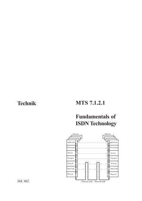
4 The OSI reference model<br />
The OSI reference model (OSI = Open System<br />
Interconnection) was developed by the ISO (International<br />
Standardisation Organisation), a<br />
body which develops and publishes worldwide<br />
standards for all disciplines including telecommunications<br />
technology.<br />
The OSI reference model is a conceptual model<br />
which is derived from computer engineering and<br />
aims to guarantee compatibility between systems<br />
that conform to its specifications. It divides the<br />
process of communication by means of telecommunications<br />
technology into seven layers, each<br />
of which is responsible for a certain task within<br />
the communication process.<br />
The OSI model is arranged hierarchically and is<br />
represented in one of two ways:<br />
a) Layers 5 to 7 are related to the application<br />
and are more fully specified in the application<br />
protocol. Layers 1 to 4 are transport-oriented<br />
and are concerned with the actual data<br />
transfer. The relevant processes are described<br />
in transport protocols.<br />
b) Layers 4 to 7 relate to the terminal device,<br />
i.e. the tasks these layers represent are performed<br />
by the terminal device. Layers 1 to 3<br />
are network-oriented, i.e. their part of the<br />
process is accomplished by the network itself.<br />
The entire process of communication between<br />
ISDN equipment and an exchange is described<br />
by layers 1 to 3. All the necessary information<br />
for the connection and disconnection of an<br />
ISDN link is mediated at this level. This is described<br />
more fully in the following sections.<br />
4.1 Layer 1<br />
Layer 1 (physical layer) is responsible for the<br />
physical data transfer between the terminal device<br />
and the network termination/exchange. It<br />
is used by both B and D channels. The specification<br />
for layer 1 is in CCITT recommendation<br />
I.430.<br />
An example of an interface that corresponds to<br />
layer 1 is the S 0 interface between that terminal<br />
device and the network terminal for basic access<br />
or the U k0 interface between the network<br />
termination and the exchange.<br />
The most important tasks performed in layer 1<br />
include:<br />
• Activation of a physical connection between<br />
TE and NT/exchange<br />
• Deactivation of the physical connection between<br />
TE and NT/exchange<br />
• Transparent data transfer (of D and B channel<br />
data)<br />
In the ISDN training system, the directions are<br />
confined to connections between a terminal device<br />
(TE) and the network termination (NT), i.e.<br />
the S 0 interface.<br />
4.2 Layer 2<br />
Layer 2 (Data link layer) belongs to the D channel<br />
and is responsible for ensuring security of<br />
D-channel information transferred between the<br />
terminal device and the exchange. This security<br />
function does not only involve control of the<br />
frame and the number of transmitted bits but<br />
also the monitoring of layer-3 messages as they<br />
are sent or received.<br />
The most important tasks performed in layer 2<br />
include:<br />
• synchronization of frames<br />
• error checking<br />
• transmission of acknowledged and unacknowledged<br />
messages<br />
• procedures for the assignment of addresses<br />
• establishment and ending of layer-2 connections<br />
21
22<br />
MTS 7.1.2.1 Fundamentals of ISDN Technology Theory<br />
4.3 Layer 3<br />
Layer 3 (Network layer) is responsible for the<br />
actual exchange of information between the terminal<br />
device and the exchange and thus takes<br />
on most of the work in establishing and ending<br />
connections and activation/deactivation of features.<br />
It also administers the B-channel and<br />
routes connections as appropriate. Layer 3 messages<br />
are then transported and made secure in<br />
layer 2.<br />
The most important tasks performed in layer 3<br />
include:<br />
• Establishment and ending of connections<br />
between the terminal device and the exchange<br />
• Activation and deactivation of features<br />
• Transmission of information from the terminal<br />
device and subscribers Fig. 4.3-1: OSI reference model<br />
L7 Layer 7 Application Layer<br />
L6 Layer 6 Presentation Layer<br />
L5 Layer 5 Session Layer<br />
L4 Layer 4 Transport Layer<br />
L3 Layer 3 Network Layer<br />
L2 Layer 2 Data Link Layer<br />
L1 Layer 1 Physical Layer<br />
5 S 0 interface<br />
5.1 Logical structure of the S 0 interface<br />
In terms of the OSI reference model, the S 0 interface<br />
corresponds to the physical layer, layer 1.<br />
Apart from making the physical communications<br />
medium (copper wires) available, layer 1<br />
also manages important tasks related to secure<br />
data transfer, e.g. transmission of data on the B<br />
and D channels, frame synchronisation, control<br />
of access to the D-channel and the activation of<br />
the transmission frame. In a primary multiplexing<br />
terminal, the S 2M interface fulfils a similar<br />
role. With a basic access terminal this job is<br />
handled by the S 0 interface<br />
The S 0 interface's physical structure consists of<br />
a four-wire bus connected via transformers at<br />
both the receiving and transmitting ends. Two<br />
wires are available for transmitting in either direction<br />
and data is transferred one bit at a time.<br />
This kind of communication is called serial data
MTS 7.1.2.1 Fundamentals of ISDN Technology Theory<br />
transfer.<br />
The logical structure allows each end terminal<br />
three-fold access to the S 0 interface:<br />
Fig. 5.1-1: Logical structure of the S 0 bus<br />
5.2 S 0 frame<br />
Frame pulses NT ð TE<br />
F Frame bit (synchronizes the start of a frame)<br />
L DC-bias compensation bit (parity bit) for frame<br />
bit F<br />
B1, B1 Base channels<br />
E Echo of the D channel information from the TE<br />
D D-channel information from NT ð TE<br />
A Indicates the synchronous state of the NT<br />
FA Additional frame bit (hitherto set to “0” )<br />
S1, S2 Reserved bits for future use (hitherto set to “0”)<br />
Fig. 5.2-1: Structure of S 0 frames<br />
5.3 Structure of the S 0 frame<br />
The S 0 frame consists of a total of 48 bits, whose<br />
order and purpose are precisely defined. The<br />
structure differs depending on the direction of<br />
transmission (TE → NT or NT → TE cf. S 0<br />
frame structure). The transmission time for each<br />
Every terminal has access to the two user channels<br />
B1 and B2 which support a transfer rate of<br />
64 kbits/s and to the D-channel which operates<br />
at 16 kbits/s. The B-channels are responsible for<br />
subscriber information (e.g. voice or data)<br />
while the D-channel is primarily concerned<br />
with controlling the establishment of a connection<br />
and the activation or deactivation of features.<br />
With the basic access terminal, the S 0 interface<br />
makes available a synchronous, bit-transparent<br />
and precisely defined layer-1 data transfer<br />
structure for all traffic on the B and D-channels.<br />
This is the S 0 frame.<br />
Frame pulses TE ð NT<br />
F Frame bit (synchronizes the start of a frame)<br />
L DC-bias compensation bit (parity bit)<br />
– 1 bit for frame bit F<br />
– 1 bit for each group of 4<br />
Information octets (B1/B2)<br />
– 1 bit for each of the four 4 D-channel bits<br />
– 1 bit for the additional frame bit FA<br />
B1, B1 Base channels<br />
D D-channel information from TE ð NT<br />
A Indicates the synchronous state of the NT<br />
FA Additional frame bit (hitherto set to “0”)<br />
frame is defined to be 250 µs, corresponding to<br />
about 2.51 µs per bit. The voltage values representing<br />
the logical states for a bit are based on a<br />
modified version of AMI code.<br />
An overview of some of the most important bits<br />
in the S 0 frame:<br />
23
24<br />
MTS 7.1.2.1 Fundamentals of ISDN Technology Theory<br />
F bit<br />
The F bit is the one that marks the start of every<br />
S 0 frame. For this reason it only appears once in<br />
the frame and is important for synchronization<br />
of the frame since every terminal device has to<br />
correctly detect the beginning of the frame in<br />
order to engage in communication.<br />
L bit<br />
The L bit is the so-called DC-compensation bit.<br />
Its job is to ensure that its portion of a frame and<br />
thus the S 0 frame as a whole is free of any DC<br />
bias, since the line transformer cannot handle<br />
DC levels.<br />
B1, B2 bit<br />
These bits form the B1 and B2 channels and are<br />
responsible for the transmission of subscriber<br />
data. The S 0 frame transmits 16 B1 and 16 B2<br />
bits, each divided into two blocks of 8 bits.<br />
D bit<br />
The D bit transports the D channel information<br />
from TE → NT or from NT → TE. There are four<br />
D-channel bits in each S 0 frame. The D-channel<br />
protocol requires octets (an octet is 8 bits) but, as<br />
the S 0 frame contains only 4 D bits, only ½ an<br />
octet can be transmitted in each one of them.<br />
Note:<br />
One speaks of octets in ISDN because it is a bitoriented<br />
protocol. Bit-oriented means that every<br />
bit has a distinct pre-defined meaning, usually<br />
specified in a table. A byte-oriented protocol<br />
is one where separate meanings are assigned to<br />
whole bytes.<br />
E bit<br />
The echo bit exists so that D bits received at the<br />
network terminal are taken up and echoed back<br />
to the bus. Terminal devices can, for example,<br />
read the E bits to determine if the D channel is<br />
free. A device can also use the E bits to determine<br />
whether it really is connected with the D<br />
channel. The echo channel is thus an aid to access<br />
control for the D channel.<br />
5.4 S 0 interface code<br />
The selection of an appropriate basis code was<br />
made with a view to ensuring, as far as possible,<br />
that the most important requirements were cov-<br />
ered, such as timing recovery, absence of DC<br />
bias, synchronization and error limiting. The<br />
result of this selection process was the choice of<br />
modified version of AMI coding (AMI = Alternate<br />
Mark Inversion) as the template for the S 0<br />
interface.<br />
This modified AMI code specifies the following<br />
voltage values for the logical states:<br />
logical “1” is transmitted as 0 Volts<br />
(zero<br />
voltage)<br />
logical “0” is transmitted as a positive or<br />
negative<br />
voltage<br />
In addition, the following coding rules apply to<br />
transmission via the S 0 interface:<br />
• The first logical “0” of each portion of a<br />
frame is always a logical zero of negative<br />
voltage (note each frame portion ends with<br />
an L bit after which the following portion of<br />
the frame begins).<br />
• If a logical “0” of negative voltage is transmitted,<br />
the next zero must be transmitted<br />
with positive voltage and vice-versa (this<br />
applies to the whole S 0 frame)<br />
• Every portion of the frame has to be free of<br />
DC bias<br />
5.5 Violations of the coding rules<br />
The very first bit of the frame, the F bit, breaks<br />
the coding rules. The F and L bits form a partial<br />
frame. The coding rules state that the first logical<br />
zero of a partial frame should always be of<br />
negative voltage, yet the F bit is defined as a<br />
logical “0” of positive voltage. The L bit which<br />
serves to ensure that a partial frame is free of<br />
DC bias is specified to be a logical “0” of negative<br />
voltage as expected.<br />
The initial coding violation involving the F bit<br />
always leads to a second. This occurs within the<br />
first 14 bits of the S 0 frame, at the latest by the<br />
time the FA bit is reached. This is specified to be<br />
a logical “0” of negative voltage. Even if all the<br />
B1, D and L bits in the second and third parts of<br />
the frame are both logical “1” at zero voltage,<br />
the FA bit always necessarily causes the second<br />
violation.<br />
These violations of the coding rules allow a terminal<br />
device to determine the start of an S 0
MTS 7.1.2.1 Fundamentals of ISDN Technology Theory<br />
frame with certainty so that they can make sure<br />
they are synchronized.<br />
5.6 Control of access to the D channel<br />
In the case of a point-to-point connection, both<br />
layer 1 and layer 2 are always active. The PBX<br />
system is the only equipment accessing the D<br />
channel via the S 0 bus so that it does not have to<br />
compete with other transmitters.<br />
However, when a basic access terminal is in<br />
point-to-multipoint configuration (multiple-device<br />
connection), up to eight devices may be<br />
connected to the bus and all these have to share<br />
the D channel. This also applies to additional<br />
devices running the service “Datex-P on the D<br />
channel” (X.31).<br />
The S 0 bus operates on the principle of equality<br />
for all. No terminal device may interfere with<br />
the D-channel data of another. The D-channel<br />
may only be used by one device at a time. All<br />
devices must have equal priority to access the D<br />
channel.<br />
6 Layer 1<br />
When the basic access terminal is in point-topoint<br />
configuration (single device connection)<br />
this activation takes place when the PBX system<br />
is switched on. Thereafter both layer 1 and<br />
layer 2 remain active, even if neither of the B<br />
channels nor the D channel is in use. Disconnection<br />
of layer 1 usually only occurs in the<br />
case of a fault or if the equipment is intentionally<br />
switched off.<br />
If the basic access terminal is in point-tomultipoint<br />
configuration (multiple device connection),<br />
it is placed into an idle state when<br />
there is no activity on the D or B channels. This<br />
idle state is equivalent to the logical “1” state (=<br />
zero voltage). In this case, there is no S 0 frame<br />
in existence so that no data transfer between TE<br />
and NT can take place. Before a subscriber can<br />
establish a connection or the exchange relay a<br />
call when the equipment is in this state, layer 1<br />
must first be activated.<br />
For this purpose, D-channel access control was<br />
introduced.<br />
All devices connected to the S 0 bus read all the<br />
data transmitted from NT → TE on the echo<br />
channel (E bits). Devices can determine when<br />
and whether the D channel is free by counting<br />
logical “1” (0V) on the echo channel. The following<br />
number of bits must be counted by various<br />
devices before they can count on the Dchannel<br />
being free:<br />
Terminal devices<br />
with high priority 8 x logical “1”s,<br />
Terminal devices<br />
with low priority 10 x logical “1”s,<br />
Standard ISDN devices are usually high priority<br />
whilst X.31 devices are given low priority so<br />
that they do not block the D-channel.<br />
When a terminal device has counted 8 logical<br />
“1”s, it knows that the D-channel is free and<br />
that it may transmit.<br />
In order for layer 1 (Physical layer) to transfer Band<br />
D-channel data from TE → NT or vice versa,<br />
there has to exist an S 0 frame of the correct structure,<br />
i.e. layer 1 has to be activated.<br />
Fig. 6.1-1: Layer 1 activation procedure<br />
25
26<br />
MTS 7.1.2.1 Fundamentals of ISDN Technology Theory<br />
6.1 Activation procedure for layer 1<br />
If no data is being sent on either the D channel<br />
or the B channels, the S 0 interface remains in its<br />
idle state. This is characterized by a constant<br />
logical “1” (zero voltage) which the layer-1<br />
specification defined as an INFO S 0 message.<br />
If a subscriber wishes to establish communication,<br />
their terminal device initiates the activation<br />
procedure by sending the INFO S1 message.<br />
INFO S1 consists of a repetition of the binary<br />
sequence, 00111111 (positive, negative,<br />
zero voltage) at a nominal bit rate of 192 kbit/s.<br />
This acts as a kind of wake-up call to the exchange.<br />
When the exchange receives INFO S1 it replies<br />
with an INFO S2 message. INFO S2 is a complete<br />
S 0 frame with all bits in the B, D and E<br />
channels set to logical “1”. Thus the network<br />
terminal sends a signal which constantly changes<br />
from positive to negative voltage at a rate of<br />
192 kbit/s. INFO S2 is so designed that the terminal<br />
device receives a large number of pulses<br />
to which it can synchronize.<br />
The INFO S3 message allows the terminal device<br />
to convey its synchronous state to the exchange<br />
via the network terminal. INFO S3 is a<br />
complete S 0 frame which prepares the B and D<br />
channels to accept data.<br />
The exchange confirms the synchronisation<br />
and the correct frame structure by transmitting<br />
INFO S4. INFO S4 is also a complete 48-bit<br />
frame.<br />
Note:<br />
The network termination (NT) has the task of<br />
implementing layer-1 activation of the S 0 interface<br />
on the U k0 interface and vice versa (code<br />
conversion).<br />
After layer 1 has been connected, this is conveyed<br />
to layer to 2 where the necessary steps<br />
are taken (cf. layer 2). Only after communication<br />
has been established on layer 2 can layer 3<br />
initiate the connection requested by the subscriber,<br />
e.g. by transmitting the dialed number<br />
to the exchange.<br />
6.2 Deactivation procedure for layer 1<br />
In the point-to-multipoint case, layer 1 is deactivated<br />
again after the last device has finished its<br />
Fig. 6.2-1: Layer 1 deactivation procedure<br />
activity on the bus. This deactivation can only<br />
be managed by the exchange since only there is<br />
it known whether other terminal devices on the<br />
bus are still active.<br />
Deactivation of layer 1 is achieved by the transmission<br />
of an INFO S 0 signal (constant “1“ –<br />
zero voltage), i.e. there are no further S 0 frames<br />
in existence. The terminal device also ceases<br />
transmission of its S 0 frame and confirms deactivation<br />
by sending INFO S 0 . Thus the S 0 interface<br />
is returned to its idle state.<br />
6.3 Reactivation<br />
After the S 0 bus has returned to its idle state, outgoing<br />
and incoming connections can only be<br />
established if layer 1 is activated again (see activation<br />
procedure). If the exchange needs to relay<br />
an incoming call to a subscriber, then it has<br />
to initiate the activation of layer 1. As the direction<br />
of the INFO messages is fixed, the activation<br />
in this direction begins with the transmission<br />
of the INFO S2 frame.<br />
6.4 Measurement techniques and testing<br />
of layer 1.<br />
Test devices used for the installation and troubleshooting<br />
of ISDN equipment use two different<br />
ways of representing the activation of layer<br />
1. The activation is displayed either by means<br />
of LEDs or the INFO messages themselves are<br />
displayed on a device display or on a PC<br />
equipped with appropriate decoding software.<br />
This enables any possible loss of synchronisation<br />
on the line to be easily identified.
7 Layer 2<br />
MTS 7.1.2.1 Fundamentals of ISDN Technology Theory<br />
7.1 Functions of layer 2<br />
Layer 2 (Security layer) is managed by the D<br />
channel and is primarily responsible for the secure<br />
transmission of D-channel data between<br />
terminal devices and the exchange.<br />
The most important tasks performed in layer 1<br />
include:<br />
• establishment and ending of layer-2 connections.<br />
The assignment and administration of<br />
layer-2 addresses<br />
• transport of layer-3 messages in layer-2<br />
frames<br />
• monitoring the integrity of each individual<br />
frame<br />
• controlling the flow of messages<br />
• error checking by means of a check sum<br />
• error handling in the case of aberrations from<br />
the above<br />
7.2 Structure of layer 2<br />
The format of layer 2 corresponds essentially to<br />
the fundamentals of the HDLC protocol (High<br />
Level Data Link Control), where data is conveyed<br />
to the application level in packets. ISDN<br />
includes some specialized adaptations of the<br />
original HDLC protocol. For this reason, ISDN's<br />
layer-2 protocol is designated LAP-D (Link<br />
Access Protocol for D-Channel). It is described<br />
in the CCITT recommendations I.440 and I.441<br />
and has been incorporated into the ETS standard.<br />
These rules stipulate that all D-channel data<br />
should be packaged into frames. Every frame<br />
begins and ends with a specified bit pattern, the<br />
begin and end flags of layer 2. The D-channel<br />
data to be transmitted is located between the<br />
beginning of the frame (the begin flag) and its<br />
end (the end flag). The data is gathered into oc-<br />
tets (1 octet = 8 bits). The sequence of these<br />
octets is firmly specified (cf. structure of layer 2<br />
and structure of layer 3). The meaning and<br />
structure of each octet is also defined in specific<br />
detail.<br />
All information belonging to layer 2 is transmitted<br />
as “1/0” sequences - as it is for layer 3. The<br />
meaning of each bit or bit group is precisely<br />
defined in tables. These tables contain not only<br />
the logical role played by each bit but also a<br />
description of that role or the meaning of an individual<br />
bit.<br />
7.3 Layer 2 formats<br />
Every D-channel message consists of frequently<br />
repeated protocol elements: the start flag that<br />
specifically marks the start of a protocol message,<br />
the layer-2 address consisting of two octets,<br />
the layer-2 contents field that can cover<br />
one octet or two, the two-octet check sum and<br />
the end flag that marks when the protocol message<br />
is over.<br />
Fundamentally, layer 2 is aware of three formats,<br />
the U format, the S format and the I format.<br />
7.3.1 The U format<br />
U frames carry layer-2 or layer-3 messages as<br />
unnumbered frames. If a frame is lost during<br />
transmission, neither the exchange nor the terminal<br />
device can detect it.<br />
There are three main types of frame in the U<br />
format (U = unnumbered):<br />
1. The U format is used in establishing and ending<br />
connections in layer 2 and for error messages.<br />
The frames then take the above format<br />
Octet 1 Octets 2 & 3 Octet 4 Octets 5 & 6 Octet 7<br />
Start flag<br />
Layer 2<br />
Address<br />
Layer 2<br />
Contents<br />
Check sum End flag<br />
In this case U frames only contain layer 2 information.<br />
27
28<br />
MTS 7.1.2.1 Fundamentals of ISDN Technology Theory<br />
2. The U format is also used for the assignment<br />
of addresses (TEI management):<br />
Octett 1 Octets 2 & 3 Octet 4 Octets 5 to 9 Octets 10 & 11 Octet 12<br />
Start flag<br />
Layer 2<br />
Address<br />
Layer 2<br />
Contents<br />
In addition to the prescribed protocol elements<br />
(start and end flag, contents and check sum) this<br />
U frame transmits information pertaining to socalled<br />
TEI management (cf. address designa-<br />
3. The U format can contain layer-3 information<br />
in some cases<br />
In the case of a communication process in<br />
which a device has not been recognized as<br />
capable of supporting secure data transfer,<br />
then layer-3 messages will be sent without security<br />
information. Example: the exchange<br />
7.3.2 The S format<br />
The S format (S = supervisor) is used when the<br />
receipt of a layer-3 message is to be confirmed<br />
or when necessary to communicate that a certain<br />
layer-3 message needs to be retransmitted.<br />
S frames are also used for the continuous con-<br />
TEI Management Check sum End flag<br />
tion procedures) in octets 5 to 9, e.g. querying<br />
for a layer 2 address or the assignment or refusal<br />
of such an address.<br />
Octet 1 Octets 2 & 3 Octet 4 Octets 1 - 260 Octets 5 und 6 Octet 7<br />
Start flag<br />
Layer 2<br />
Address<br />
Layer 2<br />
Contents<br />
7.3.3 The I format<br />
The I format (information) is used for the numbered<br />
transmission of layer-3 messages. The<br />
layer-3 message is transmitted between layer 2's<br />
contents field and the check sum.<br />
Layer 3 Check sum End flag<br />
wishes to signal an incoming call to a terminal<br />
device. As the device to receive the call is not<br />
yet recognized, the layer-3 information is<br />
transmitted to the bus in an unnumbered layer-<br />
2 frame.<br />
trol and monitoring of an existing connection.<br />
With single-device terminals (Basic access terminal/point-to-point<br />
and primary multiplex terminals)<br />
the permanently active layer-2 connection<br />
between the PBX system and the exchange<br />
is maintained by the exchange of S frames.<br />
Octet 1 Octets 2 & 3 Octets 4 & 5 Octets 6 & 7 Octet 8<br />
Start flag Layer 2 Address Layer 2 Contents Check sum End flag<br />
The S frame consists entirely of layer-2 elements.<br />
As opposed to unnumbered transmission of layer-3<br />
messages in U frames, the transmission of<br />
layer-3 data in an I frame is secured by the inclusion<br />
of transmit and receive sequence<br />
counters in octets 4 and 5.<br />
Octet 1 Octets 2 & 3 Octets 4 & 5 Octets 1 - 260 Octets 6 & 7 Octet 8<br />
Start flag<br />
Layer 2<br />
Address<br />
Layer 2<br />
Contents<br />
Layer 3 Check sum End flag
MTS 7.1.2.1 Fundamentals of ISDN Technology Theory<br />
7.4 Overview of layer 2<br />
Fig. 7.4-1: Overview of layer 2<br />
This illustration shows an overview of all the<br />
layer-2 octets. Among the most informative<br />
components for technicians are the SAPI and<br />
TEI protocol elements.<br />
7.5 Protocol elements in layer 2<br />
7.5.1 SAPI - Service Access Point Identifier<br />
The SAPI element is always contained in the<br />
second octet of the layer-2 frame and consists<br />
of 6 bits. The SAPI affirms the function for<br />
which layer 2 is being used at any given time.<br />
The specification currently defines a total of<br />
four SAPI values, corresponding to four different<br />
functions.<br />
SAPI-<br />
Value Meaning<br />
0<br />
16<br />
32<br />
63<br />
Call Control Procedure “Signaling”: is<br />
used for all layer-2 connections used for<br />
the exchange of messages on<br />
layer 3<br />
Datex P on the D channel (X.31):<br />
indicates that the D channel should<br />
be used for packet oriented transfer<br />
Loop test: allows the exchange to<br />
test the line up to and including the<br />
network termination<br />
TEI management procedures: used<br />
for all layer-2 address assignment<br />
procedures<br />
all other values are reserved for future<br />
applications and may not be put to use<br />
Notes:<br />
1. SAPI values are decimal numbers.<br />
2. When an ISDN test device is used to decode<br />
the D-channel protocol, the octets<br />
containing the start flag, the end flag and the<br />
check sum (FCS) are not usually displayed!<br />
The most common values to appear as SAPI<br />
values when the D channel is monitored are 0<br />
and 63. With the help of these values it can be<br />
determined whether a message is concerned<br />
with TEI management or if a terminal device is<br />
already engaged in establishing a connection.<br />
7.5.2 TEI – Terminal Endpoint Identifier<br />
Every D-channel message has to include a layer-2<br />
address. This is called the TEI = Terminal<br />
Endpoint Identifier. It consists of 7 bits and is<br />
contained in the 3rd octet of the layer-2 frame<br />
(see frame structure).<br />
In regard to layer-2 addresses there is a vast difference<br />
between a point-to-point connection<br />
and a point-to-multipoint connection. In the<br />
former (basic access terminal and primary multiplex<br />
terminal), the TEI is given the fixed value<br />
0 by both the equipment and the exchange. This<br />
is adequate to allow perfect communication on<br />
the D-channel because there is only one transmitter<br />
or receiver on either side of the connection.<br />
With the multiple-device connection (basic access<br />
terminal – point-to-multipoint configuration),<br />
however, the exchange can have up to<br />
eight standard ISDN terminal devices at the<br />
subscriber end with which it might be communicating.<br />
At such a terminator, the assignment<br />
of layer-2 addresses is managed by having<br />
every terminal device contact the exchange for<br />
a TEI whenever it is plugged in or switched on<br />
(automatic TEI). The device is only able to<br />
work via the ISDN connection after the TEI<br />
has been assigned by the exchange. The TEI<br />
assigned to the device must then be included<br />
in every D-channel message. A device keeps<br />
this TEI until it is removed from the bus, until<br />
the power is switched off or until the exchange<br />
has a reason to deassign the TEI.<br />
For X.31 terminal devices (packet-oriented<br />
transmission on the D channel) layer-2 addresses<br />
are handled rather differently. After<br />
the customer has registered the device with<br />
their network provider, a TEI is supplied by the<br />
provider which the customer must manually<br />
set the device by hand. This TEI then remains<br />
fixed (non-automatic TEI).<br />
29
30<br />
MTS 7.1.2.1 Fundamentals of ISDN Technology Theory<br />
The specification defines the following TEI values:<br />
TEI-<br />
Value Meaning<br />
0<br />
0 - 63<br />
64-<br />
126<br />
reserved for point-to-point configuration<br />
(single device connection); valid for basic<br />
rate access and primary multiplex access<br />
non-automatic TEI; hard-programmed in<br />
the terminal device<br />
automatic TEI; assigned by the exchange<br />
upon request; valid only for the multiple<br />
device connection (basic rate access)<br />
127 common TEI, broadcast or group TEI<br />
Notes:<br />
1. TEI values are given as decimal numbers.<br />
2. The general TEI, 127, is always used when a<br />
definite TEI is not yet known, when all terminal<br />
devices are to receive a message or<br />
during the procedure for assigning address.<br />
7.6 Protocol sequence in layer 2<br />
7.6.1 TEI management (procedure for<br />
assigning addresses)<br />
The first time a terminal device is connected to<br />
the basic access terminal (in point-to-point configuration)<br />
it must request a layer-2 address<br />
(TEI) from the exchange before it can begin the<br />
actual connection process. To do so it sends the<br />
layer-2 message “ID request” (ID = identity) to<br />
Fig. 7.6-1: Procedure for assigning a TEI<br />
the exchange and waits for an “ID assign” message<br />
to acknowledge the request and supply the<br />
assigned TEI value.<br />
The exchange can also refuse to assign a TEI<br />
address, e.g. when eight TEIs have already been<br />
assigned to a single connection and all eight are<br />
still connected to the bus. If the exchange refuses<br />
the assignment of an address, it sends an “ID<br />
denied” message.<br />
Fig. 7.6-2: Denial of a TEI request<br />
Within the scope of TEI management there are<br />
other messages which are used for certain purposes:<br />
Identity check<br />
request<br />
Identity check<br />
response<br />
The ID check request message is<br />
used by exchange to check for<br />
the existence of a specific TEI<br />
value or indeed all TEIs on the<br />
bus.<br />
ID check response is the<br />
terminal device's answer to the<br />
exchange's ID check request<br />
giving its TEI value. If no<br />
response is received, the<br />
exchange deletes this TEI.<br />
Identity remove When the exchange deletes a<br />
TEI from its index, it informs<br />
the terminal devices on the bus<br />
by means of the message ID<br />
remove.<br />
Identity verify<br />
The terminal device can request<br />
the exchange to check its TEI.<br />
To do this, it send the ID verify<br />
message to the exchange. The<br />
exchange then initiates the test<br />
procedure by responding with<br />
an ID check request message.
MTS 7.1.2.1 Fundamentals of ISDN Technology Theory<br />
All TEI management procedures are protected<br />
by a time-out. Their structures are gathered together<br />
in a table.<br />
7.6.2 Establishing connection from TE →<br />
NT in layer 2<br />
Should one subscriber wish to make a call to<br />
another, the process begins with the raising<br />
of the telephone receiver. In terms of the OSI<br />
reference model this transmits a layer-3<br />
(transport layer) command for the establishment<br />
of the D-channel connection. This is the<br />
main purpose of layer 3 in this case. In order<br />
for the terminal device to send layer-3 messages<br />
to the corresponding layer at the exchange,<br />
the security functionality of layer 2 is<br />
required. In order for these functions to work<br />
correctly, layer 2 must be synchronized at the<br />
terminal and the exchange. This synchronization<br />
is achieved by the establishment of the<br />
connection on layer 2. This can occur in either<br />
direction, i.e. TE → NT or NT → TE, depending<br />
on whether it's an incoming or outgoing<br />
call.<br />
Note:<br />
Prerequisites for the establishment of a connection<br />
on layer 2 are:<br />
a) that layer 1 has been successfully activated<br />
and<br />
b) that the terminal device has already been assigned<br />
a TEI.<br />
When circumstances are positive, the establishment<br />
of a connection on layer 2 requires the<br />
exchange of just two messages:<br />
Fig. 7.6-3: Establishment of a connection on layer 2 TE → NT<br />
7.6.3 The layer-2 message SABME<br />
The SABME command (Set Asynchronous Balanced<br />
Mode Extended) instructs both the terminal<br />
device and the exchange to set their I and S<br />
frame counters to the predefined initial state of<br />
0 and to prepare for secure transfer of data. The<br />
SABME message itself is sent in an unnumbered<br />
U frame.<br />
7.6.4 The layer-2 message UA<br />
The reply to SABME is UA (Unnumbered<br />
Acknowledgement ) by which the exchange<br />
confirms that it is in a defined initial state and is<br />
prepared for secure transfer of data. The UA<br />
message itself is sent in an unnumbered U<br />
frame.<br />
Establishment of the layer-2 connection between<br />
terminal device and exchange only follows<br />
after the UA-message is received. This allows<br />
the numbered transmission of layer-3 messages<br />
to begin.<br />
7.7 I frames in layer 2<br />
After the layer-2 connection is established,<br />
layer-3 messages can now be sent in I frames.<br />
An I frame is a numbered frame which includes<br />
its transmit and receive counters within<br />
its structure. The number of layer-3 messages<br />
transmitted and received is counted so<br />
that both the terminal device and the exchange<br />
can determine whether all their messages<br />
have reached their intended destination.<br />
7.8 S frames in layer 2<br />
S frames serve to acknowledge receipt of layer-<br />
3 messages (I frames). The rule for the basic<br />
access terminal is that an acknowledgement is<br />
immediately sent in an S frame containing the<br />
appropriate receive count to confirm the receipt<br />
of every layer-3 message.<br />
There are three message altogether which can<br />
be sent in the S format:<br />
31
RR receive<br />
ready<br />
RN receive<br />
not<br />
ready<br />
32<br />
MTS 7.1.2.1 Fundamentals of ISDN Technology Theory<br />
The receiver acknowledges receipt<br />
of a layer-3 message with a receive<br />
count and confirms that it is ready<br />
to receive again.<br />
The receiver acknowledges receipt<br />
of a layer-3 message with a receive<br />
count and informs that it is<br />
currently unable to accept any<br />
further D-channel data. Readiness<br />
to respond can only be<br />
demonstrated by the further<br />
transmission of an RR message.<br />
REJ reject Reject is sent by the receiver when<br />
a layer-3 message has an incorrect<br />
count. It requests the transmitter to<br />
send a specific frame again.<br />
When a connection has eventually been established<br />
between the two subscribers, layer 2 has<br />
the task of ensuring the continuity of the connection<br />
by means of the D channel for the entire<br />
period until the connection is ended. This involves<br />
the regular exchange of supervisor messages<br />
between the terminal device and the exchange.<br />
An RR message is sent by the terminal<br />
device and, when all is well, the exchange replies<br />
with an RR message of its own.<br />
7.8.1 Ending of a layer-2 connection from<br />
TE → NT<br />
When the subscriber finishes a conversation, by<br />
hanging up the telephone for example, a command<br />
is sent instructing layer 3 to end the Dchannel<br />
connection (cf. Layer 3). When layer 3<br />
has completed this task, a basic access terminal<br />
in point-to-multipoint configuration needs its<br />
layer-2 connection to be ended as well.<br />
As in the case of establishing a layer-2 connection,<br />
ending requires the exchange of two messages:<br />
Fig. 7.8-1: Ending of a layer-2 connection from TE to NT<br />
7.8.2 The layer-2 message DISC<br />
The DISC command (DISConnect) severs the<br />
connection and deactivates layer 2. DISC is an<br />
unnumbered message sent in U format.<br />
7.8.3 The layer-2 message UA<br />
To confirm the ending of the connection and<br />
the deactivation of the layer, a UA (Unnumbered<br />
Acknowledgement ) is sent.<br />
Note:<br />
After layer 2 and layer 3 have been disconnected,<br />
as long as there are no other devices connected<br />
to the bus, the exchange will initiate the<br />
deactivation of layer 1.
8 Layer 3<br />
MTS 7.1.2.1 Fundamentals of ISDN Technology Theory<br />
8.1 Functions of layer 3<br />
Layer 3 is managed by the D-channel – just like<br />
layer 2. Its main task is the establishment and<br />
ending of connections and the activation or deactivation<br />
of features. Some of the most important<br />
functions of layer 3 include:<br />
• initiating the establishment of a call connection<br />
with the exchange (outgoing call) or<br />
with the terminal device of the subscriber<br />
who is being called (incoming call), including<br />
the transmission of telephone numbers.<br />
• ending of layer-3 connections when the subscribers<br />
have finished their communication<br />
or if a connection between them cannot be<br />
established.<br />
• management of the B channels, i.e. the assignment<br />
or enabling of a B channel or the<br />
transmission of the appropriate message<br />
when there is no longer a free B channel.<br />
• transmission of service identifiers required<br />
by the exchange or the terminal device of<br />
the party being called to monitor compatibility.<br />
• activation/deactivation of features, e.g. callforwarding,<br />
transfer of calls to other bus outlets<br />
or the display of charging information<br />
during a call.<br />
• addressing of layer-3 messages. Since several<br />
terminal devices can effectively be transmitting<br />
or receiving D-channel messages at<br />
the same time, it must be ensured that layer-<br />
3 messages can be assigned to their proper<br />
processes. This is achieved by means of layer-3<br />
addresses.<br />
• time-out function. For layer 3 too, there is<br />
a specific time-limit during which replies<br />
to a message should be received. If this<br />
period is exceeded an error procedure is<br />
initiated.<br />
• monitoring of protocol sequences within the<br />
layer. The sequence of layer-3 messages and<br />
the possible actions and responses are predetermined<br />
for all processes.<br />
8.2 Structure of layer 3<br />
Every layer-3 message is embedded in a layer-<br />
2 frame. The first layer-3 protocol element is<br />
preceded by the layer-2 header, containing the<br />
start flag, the address field (SAPI and TEI) and<br />
the contents field (control field). After the last<br />
protocol element in layer 3 comes the end of<br />
the layer-2 frame with the check sum (Frame<br />
Check Sequence = FCS) and the end flag (cf.<br />
layer 2).<br />
Layer-3 messages can be transported in two different<br />
layer-2 frames.<br />
a) as an unnumbered frame (U format) if the<br />
identity of the other party in the communication<br />
is not yet known. In this case the control<br />
field only contains one octet as the U frame<br />
doesn't include layer 2's transmit and receive<br />
sequence counters.<br />
Layer 2 Layer 2 Layer 2 Layer 3 Layer 2 Layer 2<br />
Start flag Address field Control field Message Check sum End flag<br />
b) as a numbered frame (I format) when the<br />
identity of the other party is known and secure<br />
communication is possible. An I frame<br />
has a two-octet control field with the transmit<br />
and receive sequence counters.<br />
Layer 2 Layer 2 Layer 2 Layer 3 Layer 2 Layer 2<br />
Start flag Address field<br />
Control field<br />
(counter)<br />
Message Check sum End flag<br />
33
34<br />
MTS 7.1.2.1 Fundamentals of ISDN Technology Theory<br />
8.3 Sequence of messages in layer 3<br />
Fig. 8.3-1: Overview of layer 3<br />
The sequence of messages in layer 3 is precisely<br />
defined in the specification. Note the following<br />
basic rules:<br />
a) Layer 3's so-called “header” consists of four<br />
different protocol elements which always<br />
appear in the same order:<br />
Start of layer 3: Protocol<br />
discriminator (PD)<br />
Layer-3 address: Length of call<br />
Reference,<br />
Call Reference<br />
Value (CR)<br />
Message name: Message Type (MT)<br />
b) Further messages that describe the contents<br />
in more detail follow on from these:<br />
Contents of the message: Information<br />
elements (IE)<br />
The Information elements contain, for example,<br />
information about services, call numbers,<br />
features, time and date or the reasons for the<br />
ending or failure of a connection. The length<br />
of these contents varies according to their<br />
contents.<br />
c) The total length of a layer-3 message may<br />
not be more than 260 octets.<br />
d) Every layer-3 message has its own table<br />
which precisely defines which information<br />
elements are mandatory or <strong>option</strong>al.<br />
e) Every layer-3 message is embedded in a<br />
layer-2 frame.<br />
8.4 Layer 3 messages<br />
The designation of a layer-3 message is contained<br />
in its “header” and is called Message<br />
Type (MT). The message type indicates which<br />
layer-3 is involved and the purpose of the message.<br />
There are basically five types of layer-3 message:<br />
1. Messages for the establishment of a connection<br />
All these messages have a specific role in the<br />
establishment of a connection, from the request<br />
for a connection using the B channel to display<br />
and acceptance of the call.<br />
2. Messages sent during the course of the connection<br />
It can also be necessary to exchange layer-3<br />
messages over the course of a connection, e.g.<br />
when a device is switched to another outlet on<br />
the bus.<br />
3. Messages for ending a connection<br />
When a subscriber ends communication, the<br />
disconnection process is carried out in full on<br />
layer-3. There are specific messages for this<br />
purposes.<br />
4. Miscellaneous messages<br />
Other messages communicate important information<br />
such as enquiries about system states or<br />
the handling of errors.<br />
5. Messages for the control of features<br />
The activation and deactivation of features is<br />
also accomplished by means of layer-3 messages.<br />
As well as the service features, which work<br />
on an active connection (e.g. Hold), there are<br />
others which can be operated while the connection<br />
is idle (e.g. forwarding of calls).<br />
8 7 6 5 4 3 2 1 HEX MT Short description<br />
0 0 0 0 0 0 0 0 00 Escape Code
MTS 7.1.2.1 Fundamentals of ISDN Technology Theory<br />
Messages for the establishment of connections<br />
0 0 0 0 0 0 0 1 0 1 Alerting<br />
Messages sent during the connection phase<br />
0 0 1 0 0 1 1 0 26 Resume<br />
0 0 1 0 1 1 1 0 2E Resume Ack<br />
Requests restoration of a<br />
connection after suspend<br />
Acknowledgement/<br />
restoration of a connection<br />
after resume<br />
0 0 1 0 0 0 1 0 22 Resume Reject Rejection of resume<br />
0 0 1 0 0 1 0 1 25 Suspend Suspends a transaction<br />
0 0 1 0 1 1 0 1 2D Suspend Ack Acknowledges suspend<br />
0 0 1 0 0 0 0 1 21 Suspend Reject Rejection of suspend<br />
0 0 1 0 0 0 0 0 20 User Info<br />
Messages for ending a connection<br />
0 1 0 0 0 1 0 1 45 Disconnect<br />
User-User messages during<br />
a connection<br />
Requests the ending of a<br />
connection<br />
0 1 0 0 1 1 0 1 4D Release Ends a connection<br />
0 1 0 0 1 0 1 0 4A<br />
Release<br />
Complete<br />
0 1 0 0 0 1 1 0 46 Restart<br />
Confirmation of release<br />
Initiate layer-3 reset<br />
(Error handling)<br />
0 1 0 0 1 1 1 0 4E Restart Ack Confirm layer-3 reset<br />
0 1 1 0 0 0 0 0 60 Segment<br />
0 0 1 0 0 0 0 0 20 User Info<br />
Indicates that a call has<br />
arrived<br />
0 0 0 0 0 0 1 1 3 Call Proceeding Retain dialing information<br />
0 0 0 0 0 1 1 1 7 Connect<br />
0 0 0 0 1 1 1 1 0 F Connect Ack<br />
Accept call/connection<br />
made<br />
Confirms acceptance of<br />
call<br />
0 0 0 0 0 0 1 0 2 Progress Connection information<br />
0 0 0 0 0 1 0 1 0 5 Setup<br />
Initiates establishment of a<br />
connection<br />
0 0 0 0 1 1 0 1 0 C Setup Ack Acknowledges setup<br />
Segments of a layer-3<br />
message<br />
User-user messages<br />
during a connection<br />
35
Other messages<br />
36<br />
MTS 7.1.2.1 Fundamentals of ISDN Technology Theory<br />
0 1 1 1 1 0 0 1 79<br />
Messages for service features<br />
0 0 1 0 0 1 0 0 24 Hold Hold a call<br />
0 0 1 0 1 0 0 0 28 Hold Ack Acknowledge Hold<br />
0 0 1 1 0 0 0 0 30 Hold Reject Reject Hold<br />
0 0 1 1 0 0 0 1 31 Retrieve Retrieve held call<br />
0 0 1 1 0 0 1 1 33 Retrieve Ack<br />
0 0 1 1 0 1 1 1 37 Retrieve Reject<br />
0 1 1 0 0 0 1 0 62 Facility<br />
0 1 1 0 0 1 0 0 64 Register<br />
Tab. 8.4-1: Message Types (MT) – Layer-3 messages<br />
8.5 Establishing connection from<br />
TE → NT in layer 3<br />
When a subscriber A calls another subscriber B,<br />
there are precisely three connection procedures:<br />
1. from subscriber A to the exchange (via D<br />
channel)<br />
2. from subscriber A's exchange to subscriber<br />
B's exchange (Central signalling channel No.<br />
7 = CSC #7)<br />
3. from subscriber B's exchange to subscriber<br />
B (via D channel)<br />
The sequence of D-channel messages between<br />
the subscribers have to be separately<br />
Congestion<br />
Control<br />
0 1 1 1 1 0 1 1 7B Information<br />
0 1 1 0 1 1 1 0 6E Notify<br />
0 1 1 1 1 1 0 1 7D Status<br />
Flow control for User-User<br />
service<br />
Conveys information , e.g.<br />
dialing information, ...<br />
Displays status of<br />
terminal portability<br />
Indication of state, e.g.<br />
error conditions<br />
0 1 1 1 0 1 0 1 75 Status Enquiry Requests an operating state<br />
Acknowledge/retrieve held<br />
call<br />
Reject restoration of held<br />
call<br />
Request or assignment of<br />
feature<br />
Request for feature - not<br />
based on current<br />
connection<br />
recorded for the purposes of measurement<br />
and analysed. In the case of a fault, the Dchannel<br />
data recorded at a location can only<br />
give a provisional idea of what might be occurring<br />
at the other end of the connection. An<br />
outcoming call is designated to be a connection<br />
established from TE → NT, and an incoming<br />
call is the establishment of a connection<br />
from NT → TE.<br />
The illustration below represents the successful<br />
establishment of a connection and shows the sequence<br />
of D-channel messages for both ISDN<br />
subscribers.
MTS 7.1.2.1 Fundamentals of ISDN Technology Theory<br />
Fig. 8.5-1: Successfully established connection<br />
8.5.1 Meanings of layer-3 messages during<br />
establishment of a connection<br />
SETUP The SETUP message is sent<br />
when the subscriber or the exchange<br />
wishes to establish a connection<br />
using the B channel.<br />
SETUP ACK SETUP ACKNOWLEDGE indicates<br />
to the receiver, that the request<br />
to connect itself has been<br />
accepted; however, additional<br />
information (e.g. dialing codes)<br />
is necessary to complete the connection<br />
INFO The INFORMATION message<br />
contains the information required<br />
to complete the establishment<br />
of the connection.<br />
CALL PROC CALL PROCEEDING indicates<br />
that the dialing information has<br />
been recognized as complete<br />
and the connection process has<br />
been initiated. No further information<br />
will be accepted.<br />
ALERT ALERT signals that the dialed<br />
subscriber's terminal equipment<br />
is ready to take a call (“it starts<br />
ringing”).<br />
CONN CONNECT acknowledges that<br />
the subscriber has accepted the<br />
call (e.g. by lifting the telephone<br />
receiver).<br />
CONN ACK CONNECT ACKNOWLEDGE<br />
is sent to acknowledge the receipt<br />
of CONNECT.<br />
Every layer-3 message has a defined meaning<br />
and can only be used for the function ascribed<br />
to it.<br />
8.6 Ending of a layer-3 connection<br />
from TE → NT<br />
If the caller terminates the connection, as in the<br />
following example, then it is the caller's terminal<br />
device that initiates the ending of the layer-<br />
3 connection on the D channel.<br />
Fig. 8.6-1: Ending of an active connection.<br />
8.6.1 Meanings of layer-3 messages during<br />
ending of a connection<br />
Only three messages are sent during the ending<br />
of a connection:<br />
DISC DISCONNECT sends a request<br />
the “D-channel partner” to end<br />
the connection<br />
REL RELEASE indicates that the transmitting<br />
device has switched off its<br />
channel-B connection and released<br />
both the B channel and the<br />
Call Reference.<br />
The transmitter requests its “Dchannel<br />
partner” to do the same.<br />
REL COM RELEASE COMPLETE lets the<br />
transmitter know that the B channel<br />
and call reference have indeed<br />
been released.<br />
37
38<br />
MTS 7.1.2.1 Fundamentals of ISDN Technology Theory<br />
8.7 Information elements (IE)<br />
on layer 3<br />
8.7.1 Special features of IEs<br />
Information elements are the actual detailed<br />
content of a layer-3 message. The use of information<br />
elements is either mandatory or <strong>option</strong>al<br />
depending entirely upon the type of message<br />
and the direction in which it is being transmitted.<br />
It is therefore important to know whether a<br />
message is being sent from the network to a<br />
subscriber (n ð u) or from the subscriber to the<br />
network (u ð n). When there are information<br />
elements in a message, they directly follow the<br />
octet Message Type (MT).<br />
8.7.2 Formats of IEs<br />
An information element normally consists of<br />
three components, name, length and content. In<br />
Example a)<br />
Example b)<br />
In variable length information elements, the extension<br />
bit (bit 8 of the first octet) is set to 0.<br />
Here the following rules apply:<br />
• If the extension bit is 0, then it is a variablelength<br />
information element.<br />
• The remaining seven bits of the first octet<br />
Example c): Information element of variable length<br />
some cases there are no contents when the message<br />
type contains in itself all the necessary information.<br />
The information element has two different formats:<br />
• Information elements the length of a single<br />
octet<br />
• Information elements of variable length<br />
For single-octet information elements, bit 8 is<br />
set to 1. This bit is the so-called “extension bit”,<br />
a mechanism which allows the receiver to recognize<br />
whether or not there are further octets in<br />
the present group. If the extension is set, there<br />
are no further octets.<br />
In a single-octet information element the extension<br />
bit signalling the length is followed by the<br />
name and any contents which fit into the single<br />
octet.<br />
contain the name of the information element.<br />
• The second octet contains the length of the<br />
message.<br />
• The length is the number of octets following<br />
the length-octet (not including it).
MTS 7.1.2.1 Fundamentals of ISDN Technology Theory<br />
There are also further rules for variable-length<br />
information elements which should be noted<br />
• The contents of an information element itself<br />
can be subdivided into individual octets or<br />
octet groups<br />
• Each octet group is a separate entity.<br />
8.7.3 An overview of the most important information elements<br />
• The sequence of octets within an information<br />
element is predefined and may not be<br />
altered.<br />
• A table indicates whether an octet or octet<br />
group is mandatory or <strong>option</strong>al for an information<br />
element<br />
8 7 6 5 4 3 2 1 Hex IE Meaning<br />
1 0 1 0 0 0 0 0 A0<br />
0 0 0 0 0 1 0 0 04<br />
Sending<br />
complete<br />
Bearer<br />
capability<br />
Call number complete<br />
0 0 0 0 1 0 0 0 08 Cause Error cause<br />
0 0 0 1 1 0 0 0 18<br />
Channel<br />
identification<br />
Transmission capacity of<br />
network<br />
Channel information<br />
0 0 0 1 1 1 0 0 1C Facility Control of features<br />
0 0 1 0 1 0 0 1 29 Date / Time Datum / Zeit<br />
0 1 1 0 1 1 0 0 6C<br />
0 1 1 1 0 0 0 0 70<br />
0 1 1 1 1 1 0 0 7C<br />
0 1 1 1 1 1 0 1 7D<br />
0 1 0 0 1 1 0 0 4C<br />
8.8 Call numbers in information<br />
elements<br />
The call number assigned by the network provider<br />
(cf. features MSN and DDI) can be distinguished<br />
by two sorts of information elements<br />
which are independent of the direction of transmission.<br />
1. The number of the subscriber wishing to establish<br />
the connection is called the Calling<br />
Calling Party<br />
Number<br />
Called Party<br />
Number<br />
Low Layer<br />
Compatibility<br />
High Layer<br />
Compabitility<br />
Connected<br />
number<br />
Party Number (CGPN).<br />
Caller's number<br />
Number of person receiving<br />
the call<br />
Transmission service for<br />
layers 1-3 on the B channel<br />
Transmission service for<br />
layers 4-7 on the B channel<br />
Number of the connected<br />
subscriber<br />
2. The number of the subscriber receiving the<br />
call is termed the Called Party Number<br />
(CDPN).<br />
The numbers of both subscribers are thus conveyed<br />
via the D-channel in different information<br />
elements.<br />
Call number Information element Abbreviation<br />
Caller Calling party number CGPN<br />
Callee Called party number CDPN<br />
39
40<br />
MTS 7.1.2.1 Fundamentals of ISDN Technology Theory<br />
When establishing a connection, the dialing information<br />
plays an important part in some senses,<br />
e.g.:<br />
• The destination number can be transmitted<br />
as a block or as individually dialed digits -<br />
depending on the way the subscriber has actually<br />
dialed.<br />
• The source and destination numbers are important<br />
for various features (e.g. CLIP, CLIR<br />
or CF),<br />
• The call numbers of both the caller and the<br />
called party are usual exchanged via the D<br />
channel.<br />
• Dialed digits can, depending on the application,<br />
be transmitted in individual layer-3<br />
messages.<br />
Fig. 8.9-1: Individual dialing<br />
8.9 Transmission of dialing information<br />
in an outgoing call<br />
A simple example from everyday practice demonstrates<br />
the information elements CGPN and<br />
CDPN: A subscriber A connected to the network<br />
in Bremen (dialing code 0421) wishes to<br />
call directory enquiries (the number: 11833)<br />
from a multiple device connection. Subscriber<br />
A has entered the MSN 9801736 into their own<br />
ISDN telephone.<br />
The transmission of the destination number depends<br />
on what the subscriber does.<br />
8.9.1 Individual dialing<br />
This happens when the subscriber raises the telephone<br />
receiver and then taps in the individual<br />
digits of the number they wish to reach. The<br />
protocol for this is as follows:
MTS 7.1.2.1 Fundamentals of ISDN Technology Theory<br />
Lifting the receiver causes the subscriber's telephone<br />
to send the exchange a SETUP message,<br />
informing it of the desire to establish a connection.<br />
Since subscriber A has a full MSN entered in the<br />
telephone, the SETUP message includes this<br />
number as the CGPN.<br />
The exchange responds to the SETUP message<br />
with SETUP ACKNOWLEDGE, indicating to<br />
the terminal device that the request to establish<br />
a connection has been accepted but the necessary<br />
dialing information still needs to be sent.<br />
If the subscriber taps in all the digits of the destination<br />
number one by one, each one is transmitted<br />
in its own layer-3 INFORMATION message<br />
as the information element CDPN.<br />
8.9.2 Block dialing<br />
Block dialing implies that the entire destination<br />
number is sent in a single block, such as when<br />
the subscriber calls a number that has been<br />
saved in the telephone's memory and only lifts<br />
the receiver afterwards.<br />
Fig. 8.9-2: Block dialing<br />
Subscriber A already has a full MSN programmed<br />
and the number is sent as the CGPN<br />
in the SETUP message when using the blockdialing<br />
procedure too.<br />
As the called number is known before the raising<br />
of the receiver, the telephone can also transmit<br />
this number to the exchange in the outgoing<br />
SETUP message where it is contained in the<br />
CDPN information element.<br />
Notes:<br />
The D-channel protocol is, of course, different<br />
if subscriber A has not programmed an MSN or<br />
has entered it only partially.<br />
If the D-channel data is recorded at the receiving<br />
end of the connection, the picture also looks<br />
different.<br />
8.10 The Calling Party Number<br />
IE CGPN<br />
The calling party number identifies the caller's<br />
number.<br />
If the caller's terminal device has its phone<br />
number programmed into it, then this number<br />
is sent to the exchange as CGPN within the<br />
outgoing SETUP message. The exchange<br />
adds the local dialing code to this and switches<br />
the call into the network to reach the called<br />
number's local exchange. This exchange then<br />
passes the caller's number to the destination<br />
as the CGPN in the incoming SETUP message<br />
(as long as this is permitted by the CLIP feature).<br />
8.10.1 Structure of the Calling Party<br />
Number IE CGPN<br />
The structure and the purpose of all bits within<br />
information elements is defined in ETS 300<br />
102-1. The calling party number is an information<br />
element of variable length depending<br />
41
42<br />
MTS 7.1.2.1 Fundamentals of ISDN Technology Theory<br />
on the length of the call number being transmitted.<br />
Explanations:<br />
1. The first octet of the information element<br />
contains the element's ID. Calling party<br />
number (CGPN) is identified by the hex code<br />
6C.<br />
2. As bit 8 of the 1st octet is a 0, the IE is of<br />
variable length. That means that the 2nd octet<br />
contains the length of the element. This<br />
length is the number of octets to follow.<br />
3. Within some octets, a sequence of bits may<br />
be specifically defined (e.g. Type of<br />
number). These are specified in separate tables.<br />
4. There are four bit sequences in the CGPN<br />
element which have their own ID:<br />
Type of<br />
number: indicates whether the number is,<br />
for example, national, international<br />
or network-specific. If the<br />
terminal device does not recognize<br />
the type of number, this section<br />
is marked “unknown”<br />
Numbering<br />
plan<br />
identification: indicates the numbering plan of<br />
the terminal device, e.g. ISDN /<br />
telephone number plan, data or<br />
telex number plan. If the number<br />
plan is not known, this section is<br />
marked “unknown”<br />
Presentation<br />
indicator: specifies whether the call<br />
number may be displayed or not<br />
Screening<br />
indicator: indicates, for example, whether<br />
the number has been checked for<br />
validity by the exchange<br />
5. The numbers themselves are coded according<br />
to International Alphabet No. 5 (IA5).<br />
8.10.2 Example of the coding of a CGPN<br />
Subscriber A from the previous example has the<br />
MSN 9801736 entered into the ISDN telephone<br />
and is agreed to having the call number displayed<br />
on subscriber B's telephone. The calling<br />
party number information element is sent in the<br />
outgoing SETUP message where it appears in<br />
the following manner:<br />
Binary Hex Meaning<br />
0110 1100 6C<br />
0000 0001 01<br />
1000 0000 80<br />
Name = Calling party<br />
number<br />
09 Length: 9 octets to follow<br />
Type of call number:<br />
unknown<br />
Call number plan:<br />
ISDN/Telephone plan<br />
Call number may be<br />
displayed<br />
0011 1001 39 Number: 9<br />
0011 1000 38 Number: 8<br />
0011 0000 30 Number: 0<br />
0011 0001 31 Number: 1<br />
0011 0111 37 Number: 7<br />
0011 0011 33 Number: 3<br />
0011 0110 36 Number: 6<br />
8.11 The features CLIP and CLIR on<br />
the D channel<br />
The calling party number information element<br />
clearly shows how easy it is to change the CLIP<br />
and CLIR features on the D channel. Bits 6 and<br />
7 of octet 3a are defined as the presentation indicator:
MTS 7.1.2.1 Fundamentals of ISDN Technology Theory<br />
A table in the original specification lists the binary<br />
values that the presentation indicator can<br />
assume and the meaning of these values:<br />
Octet Bits binary Meaning<br />
3a 7 – 6 00 Display permitted<br />
01 Display suppressed<br />
10<br />
Called number not<br />
available<br />
11 Reserved<br />
If subscriber A is making use of the CLIP feature,<br />
the presentation indicator element in the<br />
transmission protocol for the transfer of the<br />
caller's number (calling party number) is set<br />
to 00 and the exchange at the destination end<br />
sends the caller's number to subscriber B via<br />
the D channel.<br />
If the caller activates CLIR, however, the terminal<br />
device sets the presentation indicator in the<br />
CGPN information element to 01. This is how<br />
subscriber B's local exchange can recognize<br />
that it is not permitted to pass the number on to<br />
the destination.<br />
Note:<br />
Whether or not subscriber A wishes the number<br />
to be displayed, it will still be sent along the<br />
network as far as the destination exchange. It is<br />
only this final exchange that interprets the presentation<br />
indicator and acts accordingly.<br />
8.12 The HOLD feature<br />
on the D channel<br />
In contrast to the CLIP and CLIR features,<br />
which can be implemented in two bits, the activation<br />
and deactivation of the HOLD feature<br />
require their own layer-3 messages.<br />
Bits Hex Message Meaning<br />
0010 0100 24 Hold<br />
0010 1000 28 Hold Ack<br />
0011 0000 30 Hold Reject<br />
0011 0001 31 Retrieve<br />
0011 0011 33<br />
0011 0111 37<br />
Retrieve<br />
Ack<br />
Retrieve<br />
Reject<br />
The terminal<br />
device requests<br />
that the exchange<br />
hold the call<br />
The exchange<br />
confirms that the<br />
call is held<br />
The exchange<br />
rejects the<br />
terminal device's<br />
request<br />
The terminal<br />
device requests<br />
that the exchange<br />
restore the held<br />
call<br />
The exchange<br />
restores the<br />
connection to the<br />
terminal device<br />
The exchange<br />
rejects the<br />
requested<br />
connection<br />
8.12.1 Activation of Hold<br />
When a subscriber puts a connection on hold,<br />
the following layer-3 messages are exchanged<br />
between the terminal device and the exchange:<br />
Fig. 8.12-1: Activation of Hold<br />
43
44<br />
MTS 7.1.2.1 Fundamentals of ISDN Technology Theory<br />
The terminal device sends the HOLD message<br />
to request the exchange to put the connection<br />
on hold and to make the B channel it had been<br />
using available for another call.<br />
By sending HOLD ACKNOWLEDGE, the exchange<br />
confirms<br />
• that the connection has been put on hold,<br />
• that the exchange at the other end has been<br />
informed that the connection is on hold<br />
• and that the B channel that had been in use is<br />
now available again.<br />
The subscriber may now use the freed B channel<br />
to accept a call or to establish a connection<br />
with another subscriber.<br />
After HOLD ACK has been received, the subscriber<br />
has three minutes to return to the held<br />
call. If this is not done, the exchange disconnects<br />
the call. Charges continue to be calculated<br />
while a call is being held.<br />
8.12.2 Deactivation of Hold<br />
Fig. 8.12-2: Deactivation of Hold<br />
To return to a held call the subscriber performs<br />
the relevant procedure on their telephone. The<br />
terminal device then sends the layer-3 message<br />
RETRIEVE to the exchange to request the connection.<br />
If the connection is still in existence,<br />
the exchange will respond to the terminal device<br />
with RETRIEVE ACKNOWLEDGE. If the<br />
time has expired, however, the exchange will<br />
refuse the request by sending RETRIEVE RE-<br />
JECT.
MTS 7.1.2.1 Fundamentals of ISDN Technology Theory<br />
9 Appendix<br />
9.1 Literature<br />
ISDN – Das neue Fernmeldenetz der Deutschen Bundespost TELEKOM<br />
Author: Peter Kahl<br />
Publisher: R. v. Decker’s<br />
3rd newly revised and expanded edition, 1990<br />
Euro-ISDN für Installateure und Service-Techniker<br />
Spath / Heermeyer<br />
Publisher Franzis, 1997<br />
Neues Terrain – ISDN erfordert fundierte Aus- und Weiterbildung<br />
Heermeyer / Spath<br />
in: Gateway, January/February 1994<br />
Neue Herausforderungen für die Berufsbildung am Beispiel der ISDN-Technik<br />
Maria Spath, in: lernen & lehren, 45, Donath-Verlag, 1997<br />
Methodisch-didaktische Umsetzung des Themas ISDN in der Berufsschule,<br />
Karl Boscher, in: lernen & lehren, 45, Donath-Verlag, 1997<br />
Qualifikation des technischen Personals bei der österreichischen Post,<br />
Hans Proksch, in: lernen & lehren, 45, Donath-Verlag, 1997<br />
Integrated Services Digital Network (ISDN); User-network interface layer 3;<br />
Specifications for basic call control, ETS 300 102-1, ETSI, 1990<br />
Illustrated ISDN – a painless primer to principles and protocols<br />
Lindgren / Jonsson, Infotrans, Sweden, 1991<br />
ISDN: The Integrated Services Digital Network: Concept, Methods, Systems<br />
P. Bocker, Springer Verlag, 1992<br />
The ISDN Literacy Book<br />
Gerald L. Hopkins, Addison-Wesley Pub Co, 1995<br />
ISDN For Dummies®<br />
David Angell, IDG Books Worldwide, 1996<br />
ISDN Explained: Worldwide Network and Applications Technology<br />
P.F. Adams / John M. Griffiths, John Wiley & Sons, 1998<br />
45
46<br />
MTS 7.1.2.1 Fundamentals of ISDN Technology Theory<br />
9.2 Overview: important causes<br />
No. Cause<br />
16 Normal call clearing<br />
17 User busy<br />
18 No user responding<br />
19 No answer from user (user alerted)<br />
21 Call rejected<br />
22 Number changed<br />
27 Number changed<br />
28 Invalid number format<br />
29 Facility rejected<br />
31 Normal, unspecified<br />
34 No circuit/channel available<br />
38 Network out of order<br />
41 Temporary failure<br />
44 Requested circuit/channel not available<br />
50 Requested facility not subscribed<br />
57 Bearer capability not authorized<br />
58 Bearer capability not presently available<br />
65 Bearer capability not implemented<br />
81 Invalid call reference value<br />
83 A suspended call exists, but this call identity does not<br />
84 Call identity in use<br />
85 No call suspended<br />
88 Incompatible destination<br />
96 Mandatory information element is missing<br />
100 Invalid information element contents<br />
Note: The complete list of failure causes for<br />
Euro-ISDN is to be found in ETS 300 102-1 or<br />
in the book Euro-ISDN für Servicetechniker<br />
und Installateure, Spath/Heermeyer, page 408.
MTS 7.1.2.1 Fundamentals of ISDN Technology Theory<br />
9.3 Abbreviations<br />
ALERT Message that indicates that the subscriber has been called (“the telephone<br />
rings”)<br />
AMI Alternate Mark Inversion<br />
AOC Advice of Charge<br />
B channel Base channel; used for speech, images, text etc.<br />
B-subscriber Dialed subscriber<br />
BC Bearer Capability<br />
CALL PROC CALL PROCEEDING; message sent in response to SETUP which confirms<br />
that the full dialing number for the destination has been included in the<br />
SETUP message.<br />
CAU Cause; information element, giving a reason for a failure<br />
CCBS Completion of Calls to Busy Subscriber = call back automatically if the line<br />
is engaged<br />
CCITT Comité Consultatif International Télégraphique et Téléphonique<br />
CDPN Called Party Number<br />
CGPN Calling Party Number<br />
CLIP Calling Line Identification Presentation = transmit the caller's number to the<br />
dialed subscriber<br />
CLIR Calling Line Identification Restriction = suppress transmission of the caller's<br />
number to the dialed subscriber<br />
COLP Connected Line Identification Presentation = transmit the number of the<br />
connected subscriber to the caller<br />
COLR Connected Line Identification Restriction = suppress transmission of the<br />
connected subscriber's number to the caller<br />
CONN CONNECT; message to confirm that the connection has been accepted<br />
CONN ACK CONNECT ACKNOWLEDGE; Response to CONNECT<br />
CR Call Reference = Layer-3 address<br />
D channel Signal channel<br />
DDI Direct Dialing In = Dialing into an ISDN switching system<br />
DISC DISCONNECT; message that initiates the ending of a connection (Layer 2<br />
or Layer 3)<br />
DSS1 Digital Subscriber Signalling System No. 1<br />
E-Bit Echo bit for a terminal device's D-channel data (S 0 frame)<br />
ETSI European Telecommunications Standards Institute<br />
ext extension<br />
F-Bit Frame bit, used for synchronising the beginning of a frame (S 0 frame)<br />
FA-Bit Additional frame bit (S 0 frame)<br />
FCS Frame Check Sequence = Layer-2 check sum<br />
HDLC High level Data Link Control<br />
47
48<br />
MTS 7.1.2.1 Fundamentals of ISDN Technology Theory<br />
HOLD Call Hold<br />
ID assign Identity assign = TEI assignment by the exchange<br />
ID denied Identity denied = refusal to assign a TEI<br />
ID request Identity request = a terminal device's request for a TEI<br />
INFO S0 Idle state of the S0 interface<br />
INFO S1 Signal to awaken the S0 interface TE ðNT<br />
INFO S2 Synchronising frame NT ðTE<br />
INFO S3 Synchronisation confirmation TE ðNT<br />
INFO S4 Synchronisations confirmation NT ðTE<br />
ISDN Integrated Services Digital Network<br />
L-Bit DC-bias compensation bit (S 0 frame)<br />
L1 layer 1 = Physical layer<br />
L2 layer 2 = Security layer<br />
L3 layer 3 = Transport layer<br />
LAPD Link Access Procedure for D-channel<br />
MGA Multiple-device connection<br />
MSN Multiple Subscriber Number = Mehrfachrufnummer<br />
MT Message Type<br />
NT Network Termination<br />
NTBA Network termination equipment for a basic-rate connection<br />
NTPMxA Network termination equipment for a primary multiplex connection<br />
OSI Open System Interconnection<br />
P-MP Point-to-multipoint (configuration)<br />
P-P Point-to-point (configuration)<br />
PCM Pulse Code Modulation<br />
PD Protocol discriminator<br />
REL RELEASE; message sent during the ending of a layer-3 connection<br />
REL COM RELEASE COMPLETE; message confirming the ending of a layer-3 connection<br />
RNR Receive Not Ready (Layer 2)<br />
S2M Interface between TE ↔ NT on primary multiplex connection<br />
SABME Set Asynchronous Balanced Mode Extended; instruction to establish a layer-2<br />
connection<br />
SAPI Service Access Point Identifier; identifies the purpose of a layer-2 connection<br />
SETUP message for initiating the establishment of a connection on layer 3<br />
SETUP ACK Acknowledgement of SETUP<br />
S0 speech<br />
Interface between TE ↔ NT on a basic-rate connection
MTS 7.1.2.1 Fundamentals of ISDN Technology Theory<br />
TA a/b Terminal adapter for analogue terminal devices<br />
TE Terminal Equipment = terminal devices (in general)<br />
TEI Terminal Endpoint Identifier = layer-2 Address<br />
TK-Anlage PBX system<br />
TP Terminal Portability = the ability to unplug from one socket on the bus and<br />
plug into another<br />
UA Unnumbered Acknowledgement (Layer 2)<br />
UAE Universal-Anschluss-Einheit (Universal telecommunications socket)<br />
UI Unnumbered Information<br />
Uk0 Interface between NT ↔ Exchange<br />
2-wire interface between PBX system and terminal equipment<br />
U P0<br />
VSt Vermittlungsstelle (Exchange)<br />
X.31 Datex-P on the ISDN-Network (B and D channel)<br />
CSC Central Signalling Channel<br />
49
50<br />
MTS 7.1.2.1 Fundamentals of ISDN Technology Exercises<br />
Equipment and accessories required<br />
MTS 7.1.2.1 Fundamentals of ISDN technology<br />
1 ISDN panel 735 912<br />
1 PBX system 735 913<br />
3 ISDN telephone 735 915<br />
1 ISDN tester 735 916<br />
Accessories<br />
1 Digital storage oscilloscope 407 575 293<br />
3 BNC cable 501 02<br />
1PC<br />
1 Book: “Fundamentals of<br />
ISDN Technology” 568 962<br />
Additional accessories for experiment 1.3:<br />
1 Star-quad cable 736 481<br />
1 Measuring bridge 736 451<br />
2 STE resistor 100 Ohm, 0,5 W 577 01<br />
1 STE capacitor 10 nF, 100 V 578 10<br />
1 STE capacitor 47 nF, 100 V 578 11<br />
1 Book: Measurements on<br />
Four Wire Lines” 568 542<br />
2 Screened cable BNC/4 mm 575 24<br />
<strong>TPS</strong> <strong>7.1.2.2</strong> Frame construction in longdistance<br />
ISDN devices<br />
1 PAM modulator 736 061<br />
1 PAM demodulator 736 071<br />
1 PCM modulator 736 101<br />
1 PCM demodulator 736 111<br />
Accessories<br />
1 Panel frame<br />
1 DC power supply ±15 V/3 A 726 86<br />
1 Spectrum analyzer 726 94<br />
2 Function generators 200 kHz 726 961<br />
1 Frequency counter 0...10 MHz 726 99<br />
1 Digital storage oscilloscope 407 575 293<br />
2 Probes 100 MHz 1.1/10:1 575 231<br />
1 Analog multimeter C.A. 406 531 16<br />
2 Cable pairs 100 cm, black 501 461<br />
3 Packs of 10 bridging plugs, black 501 511<br />
1 Book: “Pulse Code Modulation” 564 002<br />
<strong>TPS</strong> 7.1.2.3 Line codes for the<br />
S 0 interface<br />
1 Data source / parity generator 736 93<br />
1 Display / parity check indicator 736 92<br />
1 AMI/HDB3 coder 736 94<br />
1 AMI/HDB3 decoder 736 91<br />
Accessories<br />
1 Panel frame<br />
1 DC power supply ±15 V/3 A 726 86<br />
1 Digital storage oscilloscope 407 575 293<br />
2 Probes 100 MHz 1.1/10:1 575 231<br />
1 STE resistor 4,7 kOhm, 2 W 577 52<br />
1 STE capacitor 10 nF, 100 V 578 10<br />
3 Packs of 10 bridging plugs, black 501 511<br />
1 Book: “Baseband data<br />
transmission methods” 568 452
MTS 7.1.2.1 Fundamentals of ISDN Technology Exercises<br />
1 Installation techniques<br />
1.1 Configuration of the training system<br />
1.1.1 Graphic representation of the basic configuration<br />
123 ISDN Telephone (735 915) 7 PC<br />
4 PBX system (735 913) 8 Oscilloscope (575 293)<br />
5 ISDN tester (735 916) 9 ISDN panel (735 912)<br />
6 Option<br />
The experiment set-up shown here represents a configuration with the maximum amount of equipment. In the following<br />
experiments, the number of terminal devices may be less than shown for example. All the measuring equipment may also<br />
be unnecessary for some experiments.<br />
1.1.2 Quick commissioning of the PBX system<br />
EURACOM 182<br />
• Connect the EURACOM 182 to the mains (230<br />
V)<br />
• Connect the internal S0 bus of the PBX system<br />
to the ISDN panel in the following way:<br />
73513 PBX system 735912 ISDN panel<br />
(EURACOM 182)<br />
S02 → NT2 (S02)<br />
S03 → NT1 (S01)<br />
• When connecting an oscilloscope, the ground<br />
of the PBX system should be connected to the<br />
GND socket on the oscilloscope by means of<br />
the cable. This avoids problems caused by<br />
earth loops.<br />
• ISDN terminal devices (e.g. telephones) should<br />
be plugged into the Western sockets of the<br />
ISDN panel and programmed with the appro-<br />
priate MSNs (look up "setting the MSN" in the<br />
handbook for the terminal devices.)<br />
Notes:<br />
• The EURACOM 182's default settings are as<br />
follows:<br />
Port S02 Port S03<br />
20 Multiaddress<br />
call<br />
30 Multiaddress<br />
21 pre-set MSN 31 pre-set MSN<br />
22 pre-set MSN 32 pre-set MSN<br />
23 pre-set MSN 33 pre-set MSN<br />
24 pre-set MSN 34 pre-set MSN<br />
51
52<br />
MTS 7.1.2.1 Fundamentals of ISDN Technology Exercises<br />
• To start operation quickly, you may program<br />
the terminal devices with the MSNs preinstalled<br />
in the PBX system, (21..24, 31..34).<br />
• If MSNs are not programmed into the individual<br />
terminal devices, then every device on the<br />
bus will ring at once.<br />
• When the multi-address call number is active,<br />
all the devices on the bus ring together even if<br />
they are each assigned an MSN.<br />
If the MSN is incorrect or missing, the dial<br />
tone may not appear.<br />
• To alter the MSN using EURACOM 182, start<br />
the configuration program and proceed according<br />
to the handbook:<br />
System Configuration Programme<br />
Configuration<br />
Basic Configuration<br />
Assign the appropriate subscriber call number<br />
to port 2.3 or alternatively deactivate it.<br />
1.1.3 Short description of the ARGUS 10<br />
ISDN tester<br />
Please note that the operating steps and the menu<br />
entries for the Argus 10 may change should the<br />
manufacturer make alterations to the software.<br />
Important elements for operating the ARGUS<br />
test equipment<br />
→ shows the menus that can be activated by<br />
pressing the ü button.<br />
↓ allows scrolling of menu entries.<br />
ü used to activate a menu, a submenu or a procedure<br />
Press cancel to return to the previous menu or<br />
menu entry.<br />
Display<br />
Example:<br />
ARGUS 10<br />
Settings<br />
S0 NT<br />
x.xx Software version<br />
X.XX<br />
OK?<br />
P – P<br />
YES NO<br />
The first thing to do after switching on the device<br />
is to select the interface over which the test will be<br />
carried out:<br />
a) S 0 interface: for all measurements involving<br />
the S 0 bus<br />
b) analog interface (a/b-interface): for the simulation<br />
of terminal devices and operating the monitor<br />
on the a/b interface<br />
c) open, S 0 bus with no voltage applied (line test):<br />
for all physical tests<br />
The LEDs above the display show whether layer 1<br />
(S 0 interface) or layers 2 and 3 (D channel) are<br />
active. Detailed descriptions of the individual layers<br />
are to be found in the theory section.<br />
Methods of operation for the test equipment<br />
If the user wishes to test the S 0 interface, they<br />
should select that interface from the menu which<br />
brings up the display, Connection mode. By scrolling<br />
with the arrow keys and confirming with the ü<br />
key, the user can now select the operating mode<br />
for the testing device<br />
a. Automatic TE mode<br />
By activating the Automatic TE mode entry,<br />
the user causes the connection to be tested automatically.<br />
The result of this test is shown on<br />
the display. It includes details of the B channels,<br />
the interface, the configuration, the operating<br />
mode and the D-channel protocol currently<br />
in use.<br />
The second step enables the user to repeat the test<br />
or call up the main menu so that the Argus 10 device<br />
keeps the configuration that it has detected.<br />
For the user this means that further tests can be<br />
started immediately.<br />
Important: If the Argus 10 test device is used as<br />
a terminal device on the S 0 bus,the<br />
TE mode must always be selected.<br />
b. NT-S0 P-P<br />
In this operating mode the Argus 10 test device<br />
emulates two components:<br />
– in physical terms, it takes the role of the network<br />
terminal (NT) with its S 0 in point-to-point<br />
configuration, i.e. an NTBA, to which a PBX<br />
system is connected, and<br />
– in protocol terms (i.e. on the D channel), it<br />
takes the role of the exchange on layers 2<br />
and 3.<br />
This so-called NT simulation serves as the connection<br />
of a PBX system (point-to-point configuration)<br />
to the testing device.
MTS 7.1.2.1 Fundamentals of ISDN Technology Exercises<br />
c. NT-S0 P-MP<br />
In this operating mode the test device acts once<br />
again as the exchange on layers 2 and 3 in protocol<br />
terms and as the network terminal on a physical<br />
level. However, this time the configuration is<br />
point-to-multipoint so that all the terminal devices<br />
that can operate on the multiple device connection<br />
can be connected.<br />
d. S0-Monitor<br />
When used as the S 0 monitor the Argus 10 is connected<br />
across the S 0 bus where it has high impedance.<br />
Its job is then to display all protocol data,<br />
transmitted on the D channel over this interface. It<br />
doesn't matter whether this D-channel data has<br />
been sent from the network terminal or another<br />
terminal device. The test device is otherwise completely<br />
passive.<br />
Overview: Use of the Argus 10 in the experiments<br />
Automatic TE Mode menu:<br />
This instructs the equipment to test the line automatically.<br />
The Argus test equipment is usually<br />
configured for the internal S 0 interface of a Euro<br />
ISDN PBX system in point-to-multipoint mode<br />
using the Euro ISDN Protocol (DSS1).<br />
Connection menu (Individual tests):<br />
This test menu allows a connection to an external<br />
telephone number to be established (B-channel<br />
user). The service and the B channel can be selected<br />
and a number may also be dialed individually.<br />
Service features menu (Individual tests):<br />
This menu allows the availability or functionality<br />
of the features, TP, HOLD, CLIP, CLIR, COLP,<br />
COLR, CF, CCBS to be checked.<br />
Services test menu (Individual tests):<br />
This checks whether a certain service is available<br />
or working for the line under test. The<br />
service test can be carried out by self-calling or<br />
by connection with an external subscriber<br />
WinPlus and WinAnalyse<br />
Here follows a short description of how to record<br />
D-channel data using these two software packages.<br />
WinPlus and WinAnalyse should be installed<br />
on the computer according to the supplied operating<br />
manual. The WinPlus software can only show<br />
layer-2 and layer-3 messages but WinAnalyse fea-<br />
tures an additional window in which individual Dchannel<br />
messages can be shown with various<br />
depths of decoding. Both these software packages<br />
can be operated in Trace mode or Monitor mode.<br />
Recording of D-channel data in Trace mode<br />
Next the L-Test socket is connected to the serial<br />
port on the PC which has been configured by the<br />
software during installation. It is advisable to use<br />
the supplied cable for this.<br />
The next step is to start the software on the PC.<br />
The main menu should appear on the screen.<br />
The Argus 10 is now switched to Trace mode by<br />
selecting the submenu Trace mode from the Communication<br />
menu so that the Trace LED comes on<br />
After starting Trace mode you can return to any<br />
text menu to carry out a test. For this purpose, all<br />
D-channel data is automatically transmitted to the<br />
PC and shown there by the software.<br />
Definition of Trace<br />
In measurement technology, the term “trace” is<br />
similar to “record”. With an ISDN tester this<br />
means recording D-channel messages between the<br />
terminal device and the unit with which it is in<br />
communication. In the case of the TE simulation<br />
(TE mode), it is the D-channel data that the Argus<br />
10 exchanges with the PBX system or the exchange<br />
when it is emulating a terminal device.<br />
Tracing of D-channel data when operating as<br />
a passive monitor<br />
After the software is installed on the PC, the Argus<br />
10 is connected to the S 0 bus and the PC (see Argus<br />
handbook).<br />
The next steps are to start the software running on<br />
the PC and turn on the Argus 10's S 0 monitor (see<br />
Argus handbook).<br />
As soon as D-channel data appears on the S 0 bus<br />
this is conveyed to the PC and displayed with the<br />
help for the Argus software installed there.<br />
Explanation of the “passive monitor” operating<br />
mode<br />
When the Argus 10 is connected to the S 0 bus as a<br />
high impedance passive monitor, it records all Dchannel<br />
data transferred between the connected<br />
terminal devices and the PBX system or the exchange.<br />
This process allows the technician to specifically<br />
determine what data has been sent from<br />
each individual ISDN device and to discover if<br />
53
54<br />
MTS 7.1.2.1 Fundamentals of ISDN Technology Exercises<br />
there are any deviations which might indicate operational<br />
errors, programming errors or protocol<br />
errors.<br />
Further information on the operation and uses of<br />
the Argus 10 test equipment can be derived from<br />
its handbook.<br />
1.1.4 735 912 ISDN panel<br />
• Noise voltage can arise between the oscilloscope<br />
and the PBX system. This can visibly<br />
affect the oscillogram. To help avoid this the<br />
PBX system should be connected to the oscilloscope's<br />
earth socket.<br />
• The 735 912 ISDN PANEL includes 2 independent<br />
S 0 buses: S 01/2 . The buses each have<br />
their own power supply, designated NT 1/2 . The<br />
PBX system's two internal S 0 buses should be<br />
connected to these points.<br />
• To simulate both normal and emergency<br />
modes, the power supply voltage for the S 01 bus<br />
can be reversed. (EMERGENCY / NOR-<br />
MAL). This is achieved by means of ISDN's<br />
usual differential transformer.<br />
• Installation experiments (connection tests, e.g.<br />
short circuit, swapped terminal etc.) should be<br />
performed on the S 01 bus using the supplied cable.<br />
In addition, the 4-mm socket for the 736 481<br />
star quad may be connected. The terminating<br />
resistance for this bus can be switched in and out<br />
of circuit by means of the TERMINATION<br />
switch.<br />
Pay attention to this:<br />
Connection tests using the ISDN tester (735 916)<br />
can only be performed when the S 0 bus is turned<br />
off (S 01 bus = OFF), otherwise the bus lines<br />
are short-circuited by the differential transformer.<br />
For the same reason, such tests cannot<br />
be performed on S 02 either.<br />
• The power supply portion of NT 2 is decoupled<br />
from the power supply for the Trigger and<br />
Noise electronics by means of the differential<br />
transformer. The Trigger socket allows the<br />
oscilloscope to be externally triggered by a<br />
pulse. This pulse corresponds to the start of a<br />
layer-1 frame. The two sockets TE → NT (3-<br />
6) and NT → TE (4-5) represent the bits for the<br />
direction of transmission and reception on<br />
NT2.<br />
• Note:<br />
PBX systems usually maintain constant communication<br />
with the terminal devices connect-<br />
ed to them, i.e. layer 1 is never deactivated.<br />
Trigger pulses are therefore always present.<br />
The trigger ceases, however, when NOISE is<br />
switched to ON and BER is set too high (using<br />
the potentiometer). The coding violation that<br />
marks the beginning of the frame is then no<br />
longer detected.<br />
Notes on the use of the ARGUS 10 with the<br />
735 912 ISDN panel:<br />
Short-circuit test: S 01 → OFF,<br />
else display: 3,6 / 4,5<br />
short circuit<br />
Termination: ON produces the display:<br />
100 Ohm<br />
OFF produces the display:<br />
no resistance<br />
Line test: Swapped terminals, Short<br />
circuit,<br />
Termination only possible with<br />
NT 1 -S 01 . Because the differential<br />
transformer cannot be<br />
switched off, the display for<br />
S 02 is always “Short circuit”<br />
3,6 / 4,5.<br />
1.2 Installation errors<br />
1.2.1 Swapped terminals<br />
Extend an internal S 0 bus from the existing PBX<br />
system by four sockets with the help of the ISDN<br />
panel (NT1). Intentionally wire the connections to<br />
the two right-hand sockets as stated. Connect an<br />
ISDN telephone to each socket and check out the<br />
functionality of the bus with the help of these two<br />
phones.<br />
Questions<br />
1. What settings need to be set on the ISDN panel<br />
(NT 1 )?<br />
2. How should the two sockets of the ISDN panel<br />
(NT 1 ) be wired together correctly?<br />
3. What is the result of your test?<br />
4. How do the terminal devices react when you<br />
disconnect the terminating resistance? Give a<br />
reason for your result.<br />
5. How do the telephones behave when the power<br />
supply voltage is switched between normal and<br />
emergency operation? Give a reason for your<br />
result.<br />
6. How do the terminal devices behave when 1a<br />
and 1b are crossed over?<br />
7. How do the terminal devices behave when 2a<br />
and 2b are crossed over?
MTS 7.1.2.1 Fundamentals of ISDN Technology Exercises<br />
1.2.2 Resistance and wiring measurements<br />
When you install an ISDN bus for multiple devices<br />
at a customer's site, the line can be up to 150 m<br />
long and support up to 12 sockets In practice, to<br />
ensure that there are no faults with the ISDN bus,<br />
a test using appropriate measuring techniques is<br />
performed.<br />
Use the ISDN panel (NT 1 ) to take measurements<br />
on the ISDN tester which will indicate installation<br />
faults. Note the device-specific operating steps for<br />
the ISDN tester used.<br />
Note:<br />
When the wiring and resistance measurements are<br />
being performed, there must be no voltage supplied<br />
to the ISDN bus. That means that the ISDN<br />
panel (NT 1 ) must be completely disconnected<br />
from the internal S 0 interface. Furthermore, no terminal<br />
devices may be connected.<br />
When there is voltage on the bus, the red LED on<br />
the test adapter will come on.<br />
1. Use the ISDN tester to measure the resistance<br />
on a correctly wired S 0 bus.<br />
1.1 How do you connect the test equipment to the<br />
S 01 bus an, in order to take measurements?<br />
1.2 What does the ISDN tester show the results of<br />
the test to be...<br />
a) with “Termination off”?<br />
b) with “Termination on”?<br />
2. Perform the same test after creating a short<br />
circuit between 3 (2a) and 4 (1a). What does<br />
the ISDN tester show the results of the test to<br />
be?<br />
3. Use the ISDN tester along with the ISDN panel<br />
(NT1) to test for swapped terminals.<br />
3.1 How do you connect the ISDN tester to the<br />
bus for the swapped-terminals test when you<br />
want to take a measurement of the S 01 bus between<br />
the first and last sockets?<br />
3.2 What does the ISDN tester show the results of<br />
the test to be...<br />
a) with correct wiring?<br />
b) when 1a and 1b are swapped over?<br />
c) when 2a and 2b are swapped over?<br />
d) when 2a and 1b are swapped over?<br />
1.3 Line characteristics of a passive S 0<br />
bus (Option)<br />
The cable pairs of the passive S 0 bus can be more<br />
easily represented by the following equivalent cir-<br />
cuit diagram:<br />
Fig. T2.<br />
The characteristic impedance of the line can be<br />
derived from this equivalent circuit diagram:<br />
Z w =<br />
R'+ jωL' G'+ jωC' 1.3.1 Determining the line quantities per unit<br />
length using the measuring bridge<br />
1.3.2 Calculation of the characteristic impedance<br />
The experimental investigation of the S 0 bus as a<br />
data transfer medium is described in the training<br />
system MTS 7.2.4.2 Measurements on Four Wire<br />
lines.<br />
1.4 Data transfer on the physical layer<br />
The data on the receive and transmit lines of NT 2 's<br />
ISDN bus should be recorded using the oscilloscope.<br />
The oscilloscope should be triggered externally.<br />
Experiment set-up see Chapter 1.1.1.<br />
1. Connect NT2 to the PBX system then plug an<br />
ISDN telephone into a free socket.<br />
a) What does the oscilloscope show? Settings:<br />
0.5 V/cm; 10 µs/cm.<br />
b) Make a sketch of the oscilloscope display.<br />
c) Compare your sketch of the display with the<br />
S 0 frame structure. Which bits can you<br />
identify straight away?<br />
2. Lift the telephone receiver.<br />
d) How does the oscilloscope display alter?<br />
e) Where is the dial tone carried?<br />
3. Add noise to the S 0 bus by turning the potentiometer<br />
(NOISE) slowly. (Switch ON.)<br />
f) What does this noise do?<br />
4. Dial on the telephone the number of a terminal<br />
connected to the PBX system's second internal<br />
S 0 bus. Establish a connection between the two<br />
devices and conduct a call.<br />
55
56<br />
MTS 7.1.2.1 Fundamentals of ISDN Technology Exercises<br />
g) In what ways does the oscilloscope display<br />
change when you send as constant a tone as<br />
possible, e.g. a whistling noise?<br />
h) Can you conduct an analysis of the D channel<br />
using the oscilloscope as it is presently<br />
set up? Give reasons for your answer.
MTS 7.1.2.1 Fundamentals of ISDN Technology Exercises<br />
2 Services and features of ISDN<br />
2.1 Automatic line test<br />
A customer calls to report a fault. The customer is<br />
aware that they possess an ISDN line but is unable<br />
to give any technical details about it. For this reason<br />
you conduct an initial test using the ISDN tester<br />
to check<br />
• whether the B channels are present,<br />
• the interface on which the test is being performed,<br />
• the line configuration,<br />
• and the protocol the connection is using.<br />
Questions<br />
1. How can you conduct a simple automatic line<br />
test using the ISDN tester?<br />
2. What results are shown on the display after<br />
completion of the test?<br />
3. How do you interpret these results?<br />
4. How do the test results appear when a B channel<br />
is used during the course of the test? How<br />
can a B channel be occupied using the existing<br />
terminal devices for the duration of a line test?<br />
5. How do the test results appear when two B<br />
channels on the S 0 bus are used? How can you<br />
occupy both B channels on the internal S 0 bus,<br />
even though only three ISDN telephones in<br />
total are available to you? Can you achieve the<br />
exercise with only two telephones?<br />
6. How does the testing device react when it is not<br />
connected to the S 0 interface during the line<br />
test?<br />
2.2 Testing of services<br />
2.2.1 Automatic testing of services<br />
You are installing an ISDN line for a customer.<br />
After installing the NTBA and laying the S 0 bus,<br />
you wish to prove the functionality of the line. In<br />
doing this you also check whether various terminal<br />
devices (e.g. telephones, group-3 faxes, group-<br />
4 faxes etc.) can be operated on the bus, i.e. whether<br />
they can transmit and receive a call. Since you<br />
are not in possession of all these types of device<br />
where you are, use the ISDN tester to carry out this<br />
check.<br />
Experiment set-up see Chapter 1.1.1.<br />
Questions<br />
1. What sort of test can you use to check the various<br />
services most easily?<br />
2. Which test menu do you call up on the ISDN<br />
tester for this?<br />
3. How do you carry out this test with the ISDN<br />
tester? Describe the testing process step by<br />
step.<br />
4. Carry out the services test by means of selfcalling.<br />
What are the objectives of the test<br />
when calling the test device's own number?<br />
Interpret the results of the test.<br />
5. Conduct a test of services by calling an external<br />
number (= establishing connection to the<br />
S 02 bus). What are the objectives of the test<br />
when calling a different number to that of the<br />
test device? Interpret the results of the test.<br />
6. Why do the LEDs L1, L2 and L3 turn on or<br />
flash during the course of the test?<br />
2.2.2 Testing of an individual service<br />
Your customer has bought an ISDN PC card and is<br />
planning to use it as a group-3 fax receiver. The<br />
card has already been installed by the customer.<br />
As it turns out, faxes can neither been transmitted<br />
nor received, so the customer has called you to<br />
solve the problem. To find out if the terminal device<br />
service for fax group three is functioning at<br />
all on this line, you initially make use of the ISDN<br />
tester to determine whether connections using this<br />
service can be established.<br />
Experiment set-up Chapter 1.1.1.<br />
Note:<br />
1. As an alternative to a PC card the customer<br />
could be connecting a group-3 fax machine via<br />
a terminal adapter (TA a/b) or a small PBX<br />
system (point-to-multipoint configuration).<br />
Questions<br />
1. What sort of test can you use to check a specific<br />
service most easily?<br />
2. Which test menu on the do you call up on the<br />
ISDN tester for this?<br />
3. How do you carry out this test with the ISDN<br />
tester? Describe the testing process step by step.<br />
57
58<br />
MTS 7.1.2.1 Fundamentals of ISDN Technology Exercises<br />
4. What information are you given by the device's<br />
display during establishment of the connection<br />
(= dialing)?<br />
5. What is the result of the test when a connection<br />
is successfully established? How do you interpret<br />
this result?<br />
6. What is the result of the test when there is no<br />
terminal device to receive the call at the dialed<br />
number? How do you interpret this result?<br />
2.3 Features<br />
2.3.1 The Hold feature<br />
You are called to a customer on account of a fault.<br />
The customer has a multi-device basic access terminal<br />
with several telephones connected to it.<br />
According to the description of the fault, the customer<br />
is unable to use the Hold feature of their<br />
ISDN line. Because of this you are testing to see if<br />
the Hold function works properly with the help of<br />
the ISDN tester.<br />
Experiment set-up see Chapter 1.1.1.<br />
Questions<br />
1. What is the original designation for Hold in the<br />
Euro-ISDN specification?<br />
2. Why must you know the technical abbreviations<br />
and the original descriptions of a feature<br />
in practice?<br />
3. Where is the Hold feature described in detail?<br />
4. Describe the process of holding?<br />
5. State how many B channels are used by the<br />
Hold feature.<br />
6. How do you test the availability of the hold<br />
feature using the ISDN tester? Which menu do<br />
you use for the individual test? Describe the<br />
operating method step-by step.<br />
7. What result is shown when Hold is working<br />
properly at the connection (and if it isn't)?<br />
8. What reasons could there be for Hold not to<br />
work?<br />
Additional exercise<br />
Perform a Hold with an existing telephone on the<br />
PBX system's internal S 0 bus. Take note of the<br />
instructions concerning Hold in the manufacturer's<br />
manuals.<br />
Explain the process to the customer.<br />
2.3.2 The features Calling Line Identification<br />
Presentation CLIP<br />
and Calling Line Identification Presentation<br />
CLIR<br />
A customer complains that when calling the<br />
number of subscriber B, the person at the other end<br />
of the line can see the call number even though<br />
Calling Line Identification Restriction is activated.<br />
It is your task to check this statement by means<br />
of the ISDN tester and to find out where the fault<br />
lies.<br />
Experiment set-up see Chapter 1.1.1.<br />
Questions<br />
1. What are the technical abbreviations for<br />
Calling Line Identification Presentation and<br />
Calling Line Identification Restriction?<br />
2. Explain to the customer how Calling Line<br />
Identification Presentation and Calling Line<br />
Identification Restriction work?<br />
3. How does it affect Calling Line Identification<br />
Presentation on the B channel when...<br />
a) subscriber A has entered an incorrect MSN<br />
into their telephone or<br />
b) subscriber A has not entered an MSN into<br />
their telephone?<br />
4. How can you use the ISDN tester to check<br />
whether Calling Line Identification Presentation<br />
or Calling Line Identification Restriction<br />
are activated on the customer's line? Describe<br />
the method of operation step by step.<br />
5. How do you interpret the results?<br />
6. What reasons could there be for Calling Line<br />
Identification Restriction not to work?<br />
Additional exercise:<br />
Test the features Calling Line Identification Presentation<br />
and Calling Line Identification Restriction using<br />
an existing telephone on the internal S 0 bus of the<br />
PBX system. Explain the process to the customer.
MTS 7.1.2.1 Fundamentals of ISDN Technology Exercises<br />
3 D channel protocol<br />
3.1 Establishment and ending of connections<br />
on the D channel<br />
The customer complains to you of being unable to<br />
reach a certain number by telephone. You learn<br />
that the customer has a multiple device connection<br />
with more than one ISDN telephone connected.<br />
To find out whether the fault is really with your<br />
customer's system or with that of the dialed subscriber<br />
B, you establish a connection to B with the<br />
ISDN tester to check the telephone service.<br />
In order to glean an idea of the protocol sequence<br />
on the D channel at the same time, you record the<br />
D channel data using the ISDN tester and load<br />
this onto a PC. The WinPlus and WinAnalyse<br />
software is available to you for the analysis of<br />
your data.<br />
As you only need to see the sequence of protocol<br />
messages, you can begin using the WinPlus software.<br />
Questions<br />
1. How do you connect the ISDN tester to the S 0<br />
bus and the PC at the same time?<br />
2. Which function do you have to activate on the<br />
ISDN tester to enable communication with the<br />
PC?<br />
3. What does Trace mode mean?<br />
4. How do you establish a connection?<br />
5. What is the sequence of data on the D channel<br />
in layer 3 when subscriber B accepts the telephone<br />
call? Create a diagram containing all the<br />
D-channel messages with their directions of<br />
transmission.<br />
6. What are the layer-3 messages that appear and<br />
what are their meanings?<br />
7. What is the sequence of data on the D channel<br />
when subscriber B has no telephone connected<br />
under the dialed number? (Draw a diagram!)<br />
To simulate this case in an experiment, remove<br />
all terminal devices from the internal S 0 bus of<br />
the dialed number (subscriber B).<br />
8. What are the layer-3 messages that are sent in<br />
this case and what are their meanings?<br />
3.2 Testing a feature with the help of<br />
D-channel information<br />
The customer has purchased top-of-the-range<br />
ISDN telephones for a basic access terminal. It<br />
isn't long before you receive a call to say there is a<br />
fault. The customer maintains that the telephones<br />
don't work because the Hold feature can't be used.<br />
Use the ISDN tester to check whether the Hold<br />
feature is available on the customer's line.<br />
To be safe, record the D-channel data exchanged<br />
during the process using the testing device and<br />
load them into the PC. You can decode them there<br />
with the help of the WinPlus software.<br />
Questions<br />
1. How do you connect the ISDN tester to the S 0<br />
bus and the PC at the same time?<br />
2. Describe, step by step, the actions needed to<br />
record the D-channel data using WinPlus.<br />
3. How do you test the Hold function using the<br />
ISDN tester?<br />
4. What result is shown on the ISDN tester?<br />
5. What layer-3 D-channel data is sent during the<br />
test procedure? Prepare a flow diagram.<br />
6. What are the layer-3 messages that are sent in<br />
this case and what are their meanings?<br />
59
60<br />
MTS <strong>7.1.2.2</strong><br />
7.1.2.1 Fundamentals of ISDN Technology Exercises<br />
4 Frame structure on the ISDN telephone (<strong>option</strong> <strong>TPS</strong> <strong>7.1.2.2</strong>)<br />
In order to be transmitted via ISDN, speech needs<br />
to be converted by an analogue to digital converter.<br />
The data so created is bundled into the B channel<br />
of the S0 frame. The bundling of the B channels<br />
in ISDN is achieved on the S 0 bus using a 2channel<br />
PCM transmission method. ISDN<br />
telephones are the most important group of terminal<br />
devices using the system. They perform 3 conversion<br />
steps before the analogue speech signal<br />
can be represented as digital data:<br />
• sampling<br />
• quantisation<br />
• coding<br />
To try some experiments that investigate this<br />
process more thoroughly, the <strong>TPS</strong> 7.2.2.1 Pulse<br />
Code Modulation training system is available.<br />
4.1 Sampling<br />
Sampling produces a signal that is discrete in time<br />
and has continuous values. This is the first step in<br />
the process of creating a digital signal. Sampling is<br />
a reversible process as long as the relevant conditions<br />
of the sampling theorem are fulfilled. The<br />
receiver is thus able to reproduce the signal in its<br />
entirety.<br />
There are two kinds of PAM (Pulse Amplitude<br />
Modulation)<br />
1. Natural PAM. The output of the electronic<br />
sampling circuit is a signal whole PAM pulses<br />
have an envelope that reflects that of the input<br />
signal.<br />
Natural PAM<br />
2. PAM using a sample-and-hold circuit (S&H).<br />
The PAM pulses in this case are rectangular.<br />
The amplitude corresponds to the value at the<br />
end of the sample. The differences between the<br />
two types of pulse modulation is reflected in<br />
their spectra.<br />
PAM using a sample-and-hold circuit<br />
PAM spectrum<br />
A 2-channel time multiplex system. One channel carries a<br />
sine-wave signal, the other a triangular one.<br />
4.2 Quantisation and coding<br />
The PAM signal produced by sampling is discrete<br />
in time and has continuous values. In order to convert<br />
this into a digital signal quantisation and coding<br />
must be carried out in addition. To improve the
MTS <strong>7.1.2.2</strong> 7.1.2.1 Fundamentals of ISDN Technology Exercises<br />
signal-to-noise ratio for small amplitudes, a process<br />
known as "companding" is used where the portions<br />
of the signal with small amplitudes are given<br />
finer resolution than the larger signals. The illustration<br />
shows the experimentally recorded compressor<br />
and expander characteristics.<br />
In addition, an example of non-linear quantisation<br />
is shown<br />
Compressor characteristic<br />
Expander characteristic<br />
Non-linear transmission characteristic (5 bit)<br />
The illustration below shows the meanings of the<br />
individual bits and the times at which they appear<br />
in the transmitted signal. This is simplified in the<br />
training system in that, instead of a 48-bit frame, a<br />
2 x 12 bit is transmitted. The LSB appears on the<br />
oscilloscope as the 2nd bit from the left, i.e. the<br />
second bit to be sent. The sign bit is the ninth bit in<br />
the transmission, bit 10 is the CHI and is active<br />
low. This bit is designated the frame synchronisation<br />
bit. The first bit in either channel is always<br />
low and represents the stop bit.<br />
Frame structure in a 2-channel PCM system<br />
61
62<br />
MTS 7.1.2.1 7.1.2.3 Fundamentals of ISDN Technology Exercises<br />
5 Line coding on the S 0 interface (<strong>option</strong> <strong>TPS</strong> 7.1.2.3)<br />
Data transfer on the baseband implies the transmission<br />
of data at the original frequency, i.e. unmodulated.<br />
This uses line coding and is usual behaviour<br />
in ISDN, Datex and PCM30/32.<br />
The training system <strong>TPS</strong> 7.2.5 Baseband Data<br />
Transmission contains experiments which investigate<br />
this theme more thoroughly.<br />
5.1 Serial data transfer and security<br />
Important points to consider regarding serial data<br />
transfer include problems with<br />
• timing recovery<br />
• error correction<br />
• operating methods<br />
etc.<br />
5.2 AMI code<br />
Data transfer on the S 0 interfaces employs a modified<br />
AMI code. The following illustration shows<br />
an example.
MTS 7.1.2.1 Fundamentals of ISDN Technology Answers<br />
1 Installation techniques<br />
1.2 Installation errors<br />
1.2.1 Swapped terminals<br />
1. What settings need to be entered on the ISDN<br />
panel (NT 1 )?<br />
These are the settings required for the ISDN panel<br />
(NT1):<br />
S 0 bus: ON The ISDN panel's S 01 bus<br />
must be connected to the<br />
PBX system<br />
Voltage: NORMAL public network:<br />
The network terminal<br />
(NT) supplies a normal<br />
voltage which is enough<br />
for four telephones on the<br />
internal S 0 bus:<br />
The power supply voltage<br />
for the internal S 0 bus is<br />
supplied by the PBX system.<br />
This may cause the<br />
number of telephones that<br />
can be supplied with power<br />
to be limited (take note<br />
of the operating manual)<br />
Termination: ON The line pair are terminated<br />
with a 100-Ohm terminating<br />
resistance.<br />
2. How should the two sockets of the ISDN<br />
panel (NT 1) be wired together correctly?<br />
3. What is the result of your test?<br />
When the equipment is set-up as above with the<br />
two sockets correctly wired, then both telephones<br />
connected to the S 01 bus can establish a connection<br />
at the same time, either with each other (self-calling<br />
on the bus) or to telephones on the second internal<br />
S 0 bus.<br />
4. How do the terminal devices react when you<br />
disconnect the terminating resistance? Give a<br />
reason for your result.<br />
The lack of a terminating resistance does not adversely<br />
affect the functionality of the telephones.<br />
Reason:<br />
For short lines, the laws applying to characteristic<br />
resistance are not relevant. Therefore, the terminating<br />
resistance does not matter to the functioning<br />
of the bus in this case.<br />
Since, in practice, the length of the installed line is<br />
seldom known precisely, the terminating resistance<br />
must always be built-in anyway.<br />
5. How do the telephones behave when the power<br />
supply voltage is switched between normal and<br />
emergency operation? Give a reason for your<br />
result.<br />
If neither of the telephones is authorised for emergency<br />
current operation, then both will cease to<br />
function as soon as the current is switched to<br />
emergency operation.<br />
If there is an ISDN telephone connected to the private<br />
network that is set-up for emergency operation,<br />
then this phone will continue to fulfil its basic<br />
function during emergency operation.<br />
Note:<br />
A single ISDN line supports no more than one<br />
emergency-authorised telephone.<br />
6. How do the terminal devices behave when 1a<br />
and 1b are crossed over?<br />
If 1a and 1b are crossed over, it does not affect the<br />
functionality of the telephones at all. Both calls to<br />
other devices on the bus and the establishment of<br />
communication with a second internal S 0 bus are<br />
possible.<br />
7. How do the terminal devices behave when 2a<br />
and 2b are crossed over?<br />
If 2a and 2b are swapped, however, the bus ceases<br />
to be operable, i.e. none of the telephones on the<br />
bus will work.<br />
63
64<br />
MTS 7.1.2.1 Fundamentals of ISDN Technology Answers<br />
Reason:<br />
The cable pair 2a and 2b carry data in the direction<br />
TE → NT. If they are swapped over, when two<br />
terminal devices attempt to transmit simultaneously,<br />
the first two bits of the transmission frame<br />
(the F and the L bits, see the chapter on layer 1) are<br />
cancelled out because one device is sending the F<br />
bit as a logical “1” of positive voltage and the other<br />
is sending an F bit of negative voltage. With the<br />
two devices cancelling out each other's signals in<br />
this way, the S 0 bus ceases to function.<br />
1.2.2 Resistance and wiring measurements<br />
1. Use the ISDN tester to measure the resistance<br />
on a correctly wired S 0 bus.<br />
1.1 How do you connect the test equipment to the<br />
S 01 bus in order to take measurements?<br />
For this test, the test adapter is employed along<br />
with the testing equipment. The test adapter has a<br />
Western socket on each side, one of which should<br />
be connected to the L-Test socket on the ISDN test<br />
equipment using one of the supplied S 0 cables<br />
while the other is connected via the other S 0 cable<br />
to the last socket on the ISDN panel (NT1).<br />
IS<br />
DN<br />
IS<br />
DN<br />
Caution ARGUS<br />
S-Bus :Disconec ISDN LINE TEST ADAPTER<br />
Voltage<br />
tBus from<br />
NT/<br />
PABX<br />
IS<br />
DN<br />
ARGUS 10 1.20<br />
NT-Mode L123<br />
B12<br />
S0 P-MP DSS1<br />
^ ^ ^<br />
AR<br />
GU<br />
S1<br />
2 3<br />
10 4 5 6<br />
7 8 9<br />
0 #<br />
*<br />
1.2 What does the ISDN tester show the results of<br />
the test to be...<br />
a) with “Termination off”?<br />
b) with “Termination on”?<br />
Termination on:<br />
Line test<br />
Line ok<br />
Impedance: 100 Ω<br />
Termination off:<br />
Line test<br />
Line ok<br />
No impedance<br />
Note:<br />
When “Line ok” is shown on the tester, it indicates<br />
that there is no short circuit.<br />
2. Perform the same test after creating a short<br />
circuit between 3 (2a) and 4 (1a). What does<br />
the ISDN tester show the results of the test to<br />
be?<br />
Line test<br />
Short circuit<br />
3, 4<br />
Note:<br />
Any possible combination can be checked at this<br />
point!<br />
3. Use the ISDN tester along with the ISDN panel<br />
(NT1) to test for swapped terminals.<br />
3.1 How do you connect the ISDN tester to the<br />
bus for the swapped-terminals test when you<br />
want to take a measurement of the S 01 bus between<br />
the first and last sockets?<br />
For the wiring test, the ISDN testing device is once<br />
again used in conjunction with the test adapter.
MTS 7.1.2.1 Fundamentals of ISDN Technology Answers<br />
a) The L-Test socket on the ISDN tester is connected<br />
with the so-called S 0 cable directly to<br />
the first socket on the ISDN panel (NT1).<br />
b) The test adapter is connected via the second S 0<br />
cable to the last socket on the ISDN panel<br />
(NT1).<br />
ISDN<br />
3.2 What does the ISDN tester show the results of<br />
the test to be...<br />
a) with correct wiring?<br />
Line test<br />
Line ok<br />
S-Bus<br />
Voltage<br />
Impedance: 100 Ω<br />
b) when 1a and 1b are swapped over?<br />
Line test<br />
Lines crossed<br />
ISDN<br />
Caution ARGUS<br />
:Disconec ISDN LINE TEST ADAPTER<br />
tBus<br />
from NT/<br />
PABX<br />
4> 100 MΩ/km) then it is not measurable, so the assumption<br />
of G = 0 is justified.<br />
65
66<br />
MTS 7.1.2.1 Fundamentals of ISDN Technology Answers<br />
Result:<br />
Within the observed frequency range:<br />
R’≈ 117 Ω/km = Constant<br />
When f = 50 kHz increases in resistance due to<br />
skin effects become observable<br />
L’ ≈ 700 µH/km = constant<br />
G’ = 0<br />
C’ ≈ 100 nF/km = constant<br />
ωL < R<br />
1.3.2 Calculation of the characteristic impedance<br />
Graph of characteristic impedance to frequency according<br />
to empirical measurements.<br />
1.4 Data transfer on the physical layer<br />
1. Connect NT2 to the PBX system then plug an<br />
ISDN telephone into a free socket.<br />
a) What does the oscilloscope show? Settings:<br />
0.5 V/cm; 10 µs/cm.<br />
b) Make a sketch of the oscilloscope display.<br />
c) Compare your sketch of the display with the<br />
S 0 frame structure. Which bits can you identify<br />
straight away?<br />
Direction of transmission NT → TE (upper curve<br />
on oscilloscope display):<br />
The first, upward-moving pulse is the I bit of the<br />
arriving frame. It is followed by the F bit (frame<br />
bit) with which the next S 0 frame begins. According<br />
to definition, this bit is always a “positive 0”.<br />
The second, downward-moving pulse is the L bit<br />
or DC-bias compensation bit. According to definition,<br />
this is always a “negative 0”. The combination<br />
of the F bit and the L bit uniquely delineates<br />
the start of a frame.<br />
The third pulse, which also goes downwards, is<br />
the FA bit which causes a violation of the coding<br />
rules paired with the L bit. This violation makes it<br />
possible for the terminal device to uniquely determine<br />
the beginning of a frame.<br />
In the TE → NT direction (lower curve on oscilloscope<br />
display):<br />
The first, upward-moving pulse is the F bit (frame<br />
bit) with which the S 0 frame begins. According to<br />
definition, this bit is always a “positive 0”.<br />
The second, downward-moving pulse is the L bit<br />
or DC-bias compensation bit. According to definition,<br />
this is always a “negative 0”. The combination<br />
of the F bit and the L bit uniquely delineates<br />
the start of a frame.<br />
The third pulse, which also goes downwards, is<br />
the FA bit which causes violation of the coding<br />
rules paired with the second negative pulse (the 1st<br />
L bit). This violation makes it possible for the NT<br />
to uniquely determine the beginning of a frame.<br />
The fourth, upward-moving impulse is the 2nd L<br />
bit. This ensures the absence of DC bias in the<br />
partial frame containing the FA bit.<br />
2. Lift the telephone receiver.<br />
d) How does the oscilloscope display alter?
MTS 7.1.2.1 Fundamentals of ISDN Technology Answers<br />
e) Where is the dial tone carried?<br />
The F and L bits representing the start of a frame<br />
are clearly recognisable from the oscilloscope display.<br />
Then there is an alteration in the oscilloscope<br />
display between the L bit and the FA bit when the<br />
PBX system sends the terminal device a dial tone.<br />
This tone is transmitted in the B channel and this<br />
causes the alteration in the display.<br />
Note:<br />
If the PBX systems assigns the B2 channel to the<br />
terminal device, then the alteration in the oscilloscope<br />
display occurs after the FA bit, which is<br />
where the B2 channel first appears in the S 0 frame.<br />
3. Add noise to the S 0 bus by turning the potentiometer<br />
(NOISE) slowly. (Switch ON.)<br />
f) What does this noise do?<br />
The oscilloscope display shows increased interference<br />
to the display in the form of pulses. Should<br />
any of these be larger than a predefined voltage<br />
value, the S 0 bus ceases to function.<br />
Note: This process can also be demonstrated by<br />
connecting one or two terminal devices to the NT 2<br />
outlet on the ISDN panel and attempting to establish<br />
a connection with one of them. Above a certain<br />
level of interference the connection is broken.<br />
4. Dial on the telephone the number of a terminal<br />
connected to the PBX system's second internal<br />
S 0 bus. Establish a connection between the two<br />
devices and conduct a call.<br />
g) In what ways does the oscilloscope display<br />
change when you send as constant a tone as<br />
possible, e.g. a whistling noise?<br />
If a sound is sent via the telephone microphone<br />
which is as near as possible to being a monotone,<br />
then it is easy to see a clear change in the oscilloscope<br />
display. If the terminal device is assigned<br />
the B1 channel, the change will appear between<br />
the first L bit and the FA bit. If the B2 channel is<br />
active, the change only appears after the FA bit because<br />
the first B2 bits in the frame are only sent<br />
after the 2nd L bit.<br />
h) Can you conduct an analysis of the D channel<br />
using the oscilloscope as it is presently<br />
set up? Give reasons for your answer.<br />
The oscilloscope is not suitable for analysing the<br />
D channel. This requires special measuring devices<br />
as the total amount of data to be transmitted is<br />
too great even for a storage oscilloscope.<br />
Example calculation:<br />
When block dialing, the layer-3 SETUP message<br />
is assumed to consist of 50 octets (1 Octet = 8<br />
bits). However, an S 0 frame contains only 4 D bits<br />
so that for each octet, two S 0 frames need to be<br />
transmitted. This means that, even for this one layer-3<br />
SETUP message, 100 S 0 frames need to be<br />
sent and each of these 100 frames would need to<br />
be individually inspected to locate the D bits.<br />
Clearly no one can afford to go to that much trouble<br />
in practice.<br />
67
68<br />
MTS 7.1.2.1 Fundamentals of ISDN Technology Answers<br />
2 Services and Features in ISDN<br />
2.1 Automatic line test<br />
1. How can you conduct a simple automatic line<br />
test using the ISDN tester?<br />
The automatic line test can be performed either on<br />
the basic access ISDN connection or on the internal<br />
S 0 bus of the PBX system. The results of the<br />
line test on the internal S 0 bus depend on the range<br />
of services of the PBX system.<br />
To conduct an automatic line test, the ISDN tester<br />
is connected to an existing ISDN socket and<br />
turned on. After it is powered up, the menu S 0 interface<br />
and the entry automatic TE mode should<br />
be selected. The testing device now performs the<br />
test automatically and shows the results on the display<br />
after a short period.<br />
Explanation of the display:<br />
Argus 10 1.0<br />
B12<br />
S0 P-MP TE EDSS1<br />
Restart<br />
Menu<br />
Note:<br />
At the start of the line test LEDs L1, L2 and L3<br />
come on. The letter L stands for Layer and the<br />
LEDs thus apply to layer 1, layer 2 and layer 3.<br />
When the LEDs are on, it means that the layer is<br />
active, i.e. working.<br />
To find out the configuration or the protocol or<br />
whether the B channels are in use, the testing device<br />
has to establish a connection to the exchange<br />
via the D channel and thus all three layers need to<br />
be activated (see theory section).<br />
2. What results are shown on the display after<br />
completion of the test?<br />
The result of the test, as shown on the ISDN test-<br />
er's display, depends on the circumstances of the<br />
connection under test. The testing device checks<br />
whether the B channels are available and which<br />
configuration and protocol are in use on the connection.<br />
The test results are shown on the display.<br />
An example of possible test results are shown in<br />
the following solution.<br />
3. How do you interpret these results?<br />
One possible result of the automatic line test of an<br />
ISDN connection (internal S 0 bus or ISDN connection<br />
to the public telephone network) might be<br />
as follows:<br />
Argus 10 1.0<br />
B12<br />
S0 P-MP TE EDSS1<br />
Restart<br />
Menu<br />
The automatic line test shows that it has detected a<br />
basic access terminal in point to multipoint configuration<br />
using the D-channel protocol EDSS1<br />
(Euro-ISDN). Both B channels are available.<br />
4. How do the test results appear when a B channel<br />
is used during the course of the test? How<br />
can a B channel be occupied using the existing<br />
terminal devices for the duration of a line<br />
test?<br />
To occupy a B channel the easiest thing to do is to<br />
establish a connection between an ISDN telephone<br />
on the S 01 bus and one on the S 02 bus.<br />
Note:<br />
The direction of the call does not matter but the<br />
test cannot be performed until the connection between<br />
the two telephones is established.
MTS 7.1.2.1 Fundamentals of ISDN Technology Answers<br />
Argus 10 1.0<br />
B2<br />
S0 P-MP TE EDSS1<br />
Restart<br />
Menu<br />
The line test detects a basic access terminal in<br />
point-to-point configuration using the protocol<br />
EDSS-1 (Euro-ISDN), but only the B2 channel is<br />
available as B1 is already being used for another<br />
connection.<br />
5. How do the test results appear when two B<br />
channels on the S 0 bus are used? How can you<br />
occupy both B channels on the internal S 0 bus,<br />
even though only three ISDN telephones in<br />
total are available to you? Can you achieve the<br />
exercise with only two telephones?<br />
The easiest way to occupy both B channels on the<br />
internal S 0 bus is to connect two ISDN telephones<br />
to the bus and establish a connection between the<br />
two of them.<br />
Note:<br />
The direction of the call does not matter but the<br />
test cannot be performed until the connection between<br />
the two telephones is established.<br />
L2 L3<br />
Argus 10 1.0<br />
B--<br />
S0 P-MP TE EDSS1<br />
Restart Menu<br />
This basic access terminal (S 0 interface, point-tomultipoint<br />
configuration, Euro-ISDN Protocol)<br />
has no B channel available at this time. Such a<br />
case occurs, for example, when two subscribers<br />
have an active connection at the same time.<br />
6. How does the testing device react when it is not<br />
connected to the S 0 interface during the line<br />
test?<br />
In this case, the S 0 bus, upon which the line test is<br />
to be performed is disconnected from the PBX<br />
system.<br />
Argus 10 1.0<br />
No/wrong network<br />
Continue<br />
The automatic line test cannot be performed. The<br />
test equipment indicates the fact that it has been<br />
unable to detect a network as a fault. Possible reasons<br />
for this to occur include, for example, the<br />
ISDN tester not being connected to the S 0 bus at<br />
all or being connected to the wrong socket on the<br />
S 0 bus.<br />
2.2 Test of services<br />
2.2.1 Automatic testing of services<br />
1. What sort of test can you use to check a specific<br />
service most easily?<br />
In an automatic services test, the testing device<br />
uses the D-channel protocol to test whether<br />
connections can be established between the<br />
various services for terminal devices. The results<br />
are shown in simplified form on the tester's<br />
display.<br />
If a terminal device has been checked using a<br />
services test and found to be OK yet still fails to<br />
work, then the process of eliminating possible<br />
faults simply has to be continued.<br />
2. Which test menu do you call up on the ISDN<br />
tester for this?<br />
The ISDN tester's automatic service tests are started<br />
from the à Individual tests menu under the<br />
sub menu Service test.<br />
69
70<br />
MTS 7.1.2.1 Fundamentals of ISDN Technology Answers<br />
3. How do you carry out this test with the ISDN<br />
tester? Describe the testing process step by<br />
step.<br />
The menu for the individual tests is called up<br />
by pressing the ü key.<br />
• The â button can be used to scroll through the<br />
services tests<br />
• The required service test is then selected via the<br />
ü key<br />
• Now the call number can be entered.<br />
Important:<br />
By scrolling with the â button, it is possible to<br />
switch back and forth between the entry field<br />
for one's own number and that for entering an<br />
external number.<br />
• The entry of a number is confirmed with the ü<br />
key.<br />
• Now the B channel can be selected.<br />
Note:<br />
Selection of a B channel means that the test<br />
equipment requests the use of the selected B<br />
channel from the exchange. Whether it is assigned<br />
this channel, however, depends on<br />
whether the channel is free.<br />
• Next the ü key is pressed to begin the test<br />
4. Carry out the services test by means of selfcalling.<br />
What are the objectives of the test<br />
when calling the test device's own number?<br />
Interpret the results of the test.<br />
Should anyone call their own number it is called a<br />
self-call. A self-call can be used to test whether a<br />
service is working properly for both incoming and<br />
outgoing calls. For an outgoing call, the exchange<br />
accepts the service and passes it on to the dialed<br />
subscriber.<br />
A self-call can also be used to determine whether<br />
the exchange has accepted this service with the<br />
incoming call and passed it onto the connection<br />
under test so that compatible terminal devices can<br />
accept it.<br />
A self-call can help the service test achieve an accurate<br />
result, as when the test equipment is both<br />
the instigator and the receiver of a call, it can categorically<br />
determine if the transmission is reaching<br />
its own connection terminal.<br />
A self-call on the internal S 0 bus works according<br />
to the same principle as a call to the public ISDN<br />
connection. It checks to see whether the PBX system<br />
for this bus can accept a service for both incoming<br />
and outgoing calls.<br />
Possible test results for a self-call:<br />
Service outgoing incoming<br />
Tel. analogue + +<br />
Tel. ISDN + +<br />
Fax G3 + +<br />
Fax G4 + +<br />
For these services communication can be established<br />
via the tested connection for both incoming<br />
and outgoing calls.<br />
The following may be displayed as a result:<br />
+ the service is available on this bus<br />
– the service is not available on this bus<br />
* no unambiguous information on this service<br />
5. Conduct a test of services by calling a remote<br />
number (=establishing connection to the S 02<br />
bus). What are the objectives of the test when<br />
calling a different number to that of the test<br />
device? Interpret the results of the test.<br />
If a remote number is called in the testing process,<br />
there can only be a definite indication of<br />
whether a service is available (or functioning)<br />
for the local terminal.<br />
For the dialed subscriber to be able to identify<br />
the service, a compatible terminal device has to<br />
be connected and able to indicate its presence at<br />
the dialed number. If the dialed subscriber has<br />
no compatible terminal device of if a compatible<br />
device is connected there but installed under<br />
a different number, the exchange may receive<br />
no acknowledgement from the dialed system.<br />
Thus the test device making the call is informed<br />
by the exchange that the dialed subscriber has<br />
not responded. An unambiguous conclusion<br />
about the availability of the service cannot<br />
therefore be drawn.<br />
To recognise a service as being available, the<br />
ISDN tester requires the layer-3 message<br />
ALERT to be sent from the receiving terminal<br />
(meaning, "it's ringing"). This ALERT message
MTS 7.1.2.1 Fundamentals of ISDN Technology Answers<br />
can only be sent by a terminal device which is<br />
capable of using the service signalled in the incoming<br />
messages. If the ISDN tester does not<br />
receive the ALERT message, it ends the connection<br />
and normally no charges are run up.<br />
Internal S 0 bus<br />
If the service test is conducted on the internal S 0<br />
bus, an extension number belonging to another internal<br />
S 0 bus is entered as the call number of the<br />
remote subscriber. It is recommended that at least<br />
one terminal device be connected to this second S 0<br />
bus so that the result also includes an available<br />
service on the receiving side. The service test is<br />
then conducted exactly as for the public ISDN<br />
connection.<br />
To obtain an unambiguous result concerning the<br />
services available to the remote subscriber, a second<br />
ISDN tester in TE-simulation mode can be installed<br />
there which should be able to react to all<br />
incoming calls (with various services).<br />
Possible test results for a self-call:<br />
Service outgoing incoming<br />
calling called<br />
subscriber subscriber<br />
Tel. analogue + +<br />
Tel. ISDN + +<br />
Services “work” on outgoing calls from the caller<br />
and incoming calls to the remote subscriber (unambiguous<br />
information)<br />
Fax G3 + *<br />
Fax G4 + *<br />
Services “work” on outgoing calls from the caller.<br />
It is not unambiguously known whether services<br />
are supported for incoming calls to the remote subscriber.<br />
+ the service is available on the bus<br />
– the service is not available on the bus<br />
* no unambiguous information on this service<br />
6. Why do the LEDs L1, L2 und L3 turn on or<br />
flash during the course of the test?<br />
The automatic line test uses the exchange of layer-<br />
3 messages on the D channel. To test the reactions<br />
of the exchange and the remote subscriber, a layer-3<br />
connection is established for every service<br />
and the layer-3 disconnection procedure is conducted<br />
after every test is finished. In order to activate<br />
layer 3, layers 1 and 2 must already be active.<br />
When the LEDs L1, L2 and L3 are lighting<br />
up or flashing, they are indicating this activity on<br />
the layers.<br />
2.2.2 Testing of an individual service<br />
Answers<br />
1. What sort of test can you use to check a specific<br />
service most easily?<br />
The ISDN tester is used as a TE simulator, i.e. it<br />
emulates a terminal device using the group-3 fax<br />
service. A single service can be checked by having<br />
the ISDN tester establish a connection to a remote<br />
subscriber. If this outgoing call is accepted by the<br />
exchange and forwarded to the 2nd subscriber then<br />
this service is operating successfully at the existing<br />
connection.<br />
The remote subscriber can be connected to the second<br />
internal S 0 bus for the purposes of the training<br />
system. The terminal device used for this must be<br />
either a group-3 fax machine or alternatively a second<br />
ISDN test device. Note that an analog device<br />
must be connected to the S 0 bus by means of an<br />
a/b adapter.<br />
2. Which test menu on the do you call up on the<br />
ISDN tester for this?<br />
To establish a connection to a remote subscriber<br />
for a specific service, the submenu Connection<br />
under Individual tests is used.<br />
3. How do you carry out this test with the ISDN<br />
tester? Describe the testing process step by step.<br />
The steps in the process are as follows:<br />
à Individual tests ü key<br />
à Connection ü key<br />
enter remote call number and confirm with the ü<br />
key<br />
select the service using the à key<br />
confirm selection with the ü key<br />
Select the required B channel by entering 1 or 2.<br />
dialing begins when the ü key is pressed.<br />
71
72<br />
MTS 7.1.2.1 Fundamentals of ISDN Technology Answers<br />
4. What information are you given by the device's<br />
display during establishment of the connection<br />
(= dialing)?<br />
Device display<br />
Dialing<br />
Own call number<br />
To: dialed number<br />
FAX G3<br />
B channel<br />
The ISDN tester's display shows...<br />
• whether the call is being dialed (dialing),<br />
• the service with the connection is being established<br />
(Fax G3 = Group-3 Fax),<br />
• the number being sent as the tester's call<br />
number (providing the number has previously<br />
been entered into the tester),<br />
• which B channel is in use (B channel)<br />
• the number being dialed.<br />
5. What is the result of the test when a connection<br />
is successfully established? How do you interpret<br />
this result?<br />
Testing device display<br />
Connection<br />
Own call number<br />
To: dialed number<br />
FAX G3<br />
B channel<br />
Explanation:<br />
A connection is established with the group-3 fax<br />
service, i.e. the dialed subscriber has a terminal<br />
device which has accepted the call. The testing<br />
device also shows the B channel in use on the local<br />
line, the local number (provided it has been<br />
entered into the equipment) and the dialed<br />
number.<br />
Results in this case:<br />
The service is available on both this line and on<br />
the called subscriber's.<br />
Summary:<br />
If a fault remains, the process of elimination of<br />
errors should continue with a check on the hard-<br />
ware and software installation of the PC card, the<br />
terminal adapter (TA a/b) or the PBX system and<br />
its configuration (protocol, local call number etc.).<br />
6. What is the result of the test when there is no<br />
terminal device to receive the call at the dialed<br />
number? How do you interpret this result?<br />
Rejection<br />
Cause 18<br />
No answer<br />
Explanation:<br />
The testing equipment displays that the connection<br />
was refused. The number 18 is shown to identify<br />
the cause of the failure and the test device also<br />
displays that it has interpreted this to mean, "no<br />
answer".<br />
In the original Euro-ISDN specification for the<br />
D-channel protocol on layer 3 (Note: ETS 300<br />
102-1; ETS = European Telecommunication<br />
Standard) a list of possible causes for failure is<br />
defined. Each cause is assigned a number which is<br />
what the test device is showing here. A list of the<br />
most important causes is attached to the theory<br />
section as an appendix. (see 9.2).<br />
The ETS specification defines cause 18 to be “no<br />
user responding”, i.e. the dialed subscriber<br />
number has not acknowledged the presence of any<br />
suitable equipment to accept the call.<br />
Result:<br />
It can be seen that the outgoing call has reached<br />
the dialed subscriber because the number 18 for<br />
the cause of failure has been returned from there.<br />
The service is thus available at the local connection<br />
since the exchange has passed on the call to<br />
the network.<br />
Summary:<br />
In order to continue with the process of eliminating<br />
errors, it is sensible to check, amongst other things,<br />
the hardware and software installation of the PC<br />
card, of the terminal adapter or the PBX system<br />
and the configuration of the protocol, the local call<br />
number, etc.)
MTS 7.1.2.1 Fundamentals of ISDN Technology Answers<br />
2.3 Features<br />
1. What is the original designation for Hold in the<br />
Euro-ISDN Specification?<br />
The original designation for hold is Call Hold, so<br />
HOLD for short.<br />
2. Why must you know the technical abbreviations<br />
and the original descriptions of a feature<br />
in practice?<br />
It is essential to know the abbreviations used in<br />
ISDN and their precise meanings in order to properly<br />
go about the measurement of ISDN systems<br />
or devices since these terms frequently appear in<br />
the menus of many devices.<br />
3. Where is the Hold feature described in detail?<br />
Every feature is described in an ETS specification<br />
of its own. Apart from a precise definition , the<br />
specification also describes the procedures and<br />
protocol messages necessary for that feature. The<br />
HOLD feature is defined in ETS standard 300 141.<br />
Note:<br />
An overview of the features available in Euro<br />
ISDN appears in the book “Euro-ISDN für Installateure<br />
und Servicetechniker” (Spath/Heermeyer,<br />
page. 56).<br />
4. Describe the process of holding?<br />
Hold means that a subscriber has two connections<br />
established and can switch back and forth<br />
between the two of them (toggling). In this case,<br />
one B-channel is occupied by the call in progress<br />
while the second call is held at the exchange. The<br />
hold feature can take two different forms in practice:<br />
1. A second call arrives while the subscriber is already<br />
conducting a call. The subscriber wishes to<br />
accept this second call without breaking the connection<br />
to the first. By selecting the Hold feature<br />
from the menu on the telephone, the subscriber<br />
passes the existing call to the exchange where it<br />
will be held for a space of three minutes. The<br />
incoming call can then be accepted.<br />
If the subscriber wishes to continue the first conversation,<br />
there is a choice of ending the second<br />
connection so that the exchange continues to deal<br />
with the first (take note of how this works on the<br />
telephone in question!) or allowing the second<br />
call to be held at the exchange while returning to<br />
the first. In this case the subscriber can switch<br />
back and forth between the two calls.<br />
2. The second way the Hold feature can be used<br />
occurs when the subscriber is already conducting<br />
a call but then wishes to establish a second connection<br />
at the same time (consultation).<br />
In technical terms the activation and deactivation<br />
of the Hold feature is achieved by means of a<br />
specific protocol sequence on the D channel (layer<br />
3).<br />
Note:<br />
Telephone charges continue to be calculated even<br />
when a call is held.<br />
5. State how many B channels are used by the<br />
Hold feature.<br />
Only one B channel is used by the Hold feature.<br />
While the subscriber employs the B channel for<br />
the current call, the second is held at the exchange.<br />
6. How do you test the availability of the hold feature<br />
using the ISDN tester? Which menu do you<br />
use for the individual test? Describe the operating<br />
method step by step.<br />
Tests for individual features can be chosen from<br />
the Individual tests menu by selecting the submenu<br />
Features<br />
Operating steps:<br />
à Individual tests, confirm with ü key;<br />
à Features, confirm with ü key;<br />
own call number: enter, confirm with ü key;<br />
à Select HOLD test, confirm with ü key;<br />
A test of the Hold feature is then carried out automatically.<br />
7. What result is shown when Hold is working<br />
properly on the line (and if it isn't)?<br />
HOLD +<br />
The HOLD feature is available and working on<br />
this line.<br />
73
74<br />
MTS 7.1.2.1 Fundamentals of ISDN Technology Answers<br />
Result if not functioning:<br />
HOLD –<br />
The HOLD feature is not available or not working<br />
on this line.<br />
8. What reasons could there be for Hold not to<br />
work?<br />
Examples:<br />
a) the subscriber is not operating the terminal device<br />
correctly<br />
b) the feature is not supported on the line and has<br />
not been ordered.<br />
c) it was accidentally forgotten to enable the feature<br />
at the exchange.<br />
2.3.2 The features Calling Line Identification<br />
Presentation CLIP<br />
and Calling Line Identification Presentation<br />
CLIR<br />
1. What are the technical abbreviations for<br />
Calling Line Identification Presentation and<br />
Calling Line Identification Restriction?<br />
The acronym for Calling Line Identification Presentation<br />
is of course CLIP; and for Calling Line<br />
Identification Restriction, it is CLIR.<br />
It is essential to know the abbreviations used in<br />
ISDN and their precise meanings in order to properly<br />
go about the measurement of ISDN systems<br />
or devices since these terms frequently appear in<br />
the menus of many devices.<br />
Every feature is described in an ETS specification<br />
of its own. Apart from a precise definition, the<br />
specification also describes the procedures and<br />
protocol messages necessary for that feature. The<br />
CLIR feature is defined in ETS standard 300 093.<br />
Note:<br />
An overview of the features available in Euro<br />
ISDN appears in the book “Euro-ISDN für Installateure<br />
und Servicetechniker” (Spath/Heermeyer,<br />
page. 56).<br />
2. Explain to the customer how Calling Line<br />
Identification Presentation and Calling Line<br />
Identification Restriction work?<br />
a) Calling Line Identification Presentation<br />
(CLIP):<br />
The call number of subscriber A (= the subscriber<br />
making the call) is automatically<br />
conveyed to the dialed subscriber B during<br />
establishment of the connection and may,<br />
for example, be shown on the display of the<br />
ISDN telephone at the receiver end.<br />
b) Calling Line Identification Restriction<br />
(CLIR):<br />
If the caller has activated Calling Line Identification<br />
Restriction, either permanently or<br />
only for certain calls, the call number is<br />
only transmitted as far as the dialed subscriber's<br />
exchange. The exchange recognises<br />
the suppression of the caller's number<br />
and doesn't pass it on to the dialed subscribers<br />
connection.<br />
3. How does it affect Calling Line Identification<br />
Presentation on the B channel when...<br />
a) Subscriber A has entered an incorrect MSN<br />
into their telephone?<br />
b) Subscriber A has not entered an MSN into<br />
their telephone?<br />
a) incorrect MSN<br />
Public network:<br />
The telephone sends the number that has been entered<br />
into it to the exchange during establishment<br />
of a connection. In this case it would be the wrong<br />
MSN. The exchange compares the transmitted<br />
number with the block assigned to the subscriber<br />
and determines that the number is not present in<br />
this block so it ignores the received MSN and replaces<br />
it with the assigned default number for the<br />
connection and continues establishing a connection.<br />
When CLIP is activated, the dialed call is displayed<br />
a number which does belong to the caller's<br />
connection.<br />
Default number:<br />
A default number is assigned by the network provider<br />
as the subscriber's “main” telephone number<br />
and is always used when the received MSN is incorrect<br />
or no MSN is supplied.
MTS 7.1.2.1 Fundamentals of ISDN Technology Answers<br />
PBX system:<br />
Basically the behaviour of the PBX system is dependent<br />
on the manufacturer's settings or the subscriber's<br />
individual configuration. Take note of the<br />
remarks in the manufacturer's manual.<br />
If an incorrect call number is entered into a telephone<br />
connected to an internal S 0 bus, there are<br />
two possible ways that the PBX system could react,<br />
depending on the aforementioned factors:<br />
1. The PBX system could ignore the incorrect<br />
number and transmit the correct extension<br />
number to the dialed terminal device on the<br />
second internal S 0 bus.<br />
2. The PBX system refuses the call from the terminal<br />
device. In this case D-channel data<br />
should be studied to find out the precise<br />
cause for this.<br />
b) No MSN<br />
Public network:<br />
If the exchange receives no MSN with the outgoing<br />
call, it adds the default number to the call and<br />
continues establishing the connection.<br />
PBX system:<br />
The statements made under a) about the manufacturer's<br />
settings and the subscriber's configuration<br />
with regard to the way the PBX system reacts also<br />
apply here.<br />
4. How can you use the ISDN tester to check<br />
whether Calling Line Identification Presentation<br />
or Calling Line Identification Restriction<br />
are activated on the customer's connection?<br />
Describe the method of operation step<br />
by step.<br />
Operating steps:<br />
à Individual tests. Confirm with ü key;<br />
à Features, Confirm with ü key;<br />
own call number: enter, Confirm with ü key;<br />
à Select CLIP test, Confirm with ü key;<br />
The CLIP test is then conducted automatically. On<br />
this ISDN tester, the test procedure also contains a<br />
test of the CLIR, COLP and COLR features.<br />
Explanation:<br />
COLP: Connected Line Identification Presentation<br />
Transmission of the dialed subscriber's<br />
number to the caller<br />
COLR: Connected Line Identification Restriction<br />
Suppression of the transmission<br />
of the dialed subscriber's number<br />
to the caller<br />
5. How do you interpret the results?<br />
Features that have been tested are marked on the<br />
ISDN tester by a following “+” if the feature is<br />
activated or “-” if the feature is deactivated or unavailable.<br />
The results might then look like this:<br />
CLIP<br />
CLIR<br />
COLP<br />
COLR<br />
This result shows that Calling Line Identification<br />
Presentation (CLIP) is activated but Calling Line<br />
Identification Restriction (CLIR) is not, i.e. the<br />
subscriber receiving the call would normally see<br />
the number of the caller on the display of an ISDN<br />
telephone.<br />
The result also shows that the number of the subscriber<br />
accepting the call has been transmitted<br />
back to the caller (COLP). Restriction (suppression)<br />
(COLR) of this number is not activated.<br />
6. What reasons could there be for Calling Line<br />
Identification Restriction not to work?<br />
Examples:<br />
a) the feature is not supported on the line and has<br />
not been requested.<br />
b) the subscriber is not operating the terminal device<br />
correctly<br />
c) the subscriber's terminal device has faulty software<br />
d) it was accidentally forgotten to enable the feature<br />
at the exchange.<br />
+<br />
–<br />
+<br />
–<br />
75
76<br />
MTS 7.1.2.1 Fundamentals of ISDN Technology Answers<br />
3 D-channel protocol<br />
3.1 Establishment and ending of connections<br />
on the D channel<br />
Answers<br />
1. How do you connect the ISDN tester to the S 0<br />
bus and the PC at the same time?<br />
The ISDN tester is connected to the S 0 bus with<br />
the help of the S 0 connection cable. This is inserted<br />
into the S 0 bus socket; connection to the PC is<br />
made using the supplied cable via the L-Test socket.<br />
2. Which function of the ISDN tester do you have<br />
to activate to enable communication with the<br />
PC?<br />
So that the D-channel data can be transmitted from<br />
the ISDN tester to the PC, the testing device must<br />
be switched into Trace mode.<br />
The precise operating process is as follows:<br />
• Install WinPlus software onto the PC<br />
• Connect ISDN tester to the S 0 bus and the PC<br />
• Start the WinPlus Software<br />
• Start Trace mode on the test device: Submenu<br />
under the menu Communication<br />
Call Trace mode and switch on so that the<br />
LEDs are illuminated.<br />
• Conduct the test procedures<br />
Note:<br />
Two software packages are available for the ISDN<br />
tester: WinPlus and WinAnalyse. The WinPlus<br />
Software concentrates on decoding the sequence<br />
of messages whilst WinAnalyse also permits the<br />
display of the message contents (Information elements).<br />
During the first steps of the learning process,<br />
it is sufficient to see the sequence of messages<br />
using WinPlus Software.<br />
3. What does Trace mode mean?<br />
In terms of measuring technology, the word trace<br />
means the recording of steps within a process. In<br />
Trace mode the ISDN testing device records the<br />
D-channel data. The limitation is that only the Dchannel<br />
data transferred between the testing device<br />
and the destination, e.g. the exchange, can be<br />
traced.<br />
In order to trace all D-channel data appearing on<br />
an S 0 bus – i.e. the data transmitted and received<br />
from all the terminal devices on the bus, an alter-<br />
native mode is employed which is called "passive<br />
monitor operation".<br />
4. How do you establish a connection?<br />
Select the submenu Connection from the menu<br />
Individual tests. Enter the call number for the remote<br />
subscriber and the requested service then establish<br />
a connection.<br />
5. What is the sequence of data on the D channel in<br />
layer 3 when subscriber B accepts the telephone<br />
call? Create a diagram containing all the Dchannel<br />
messages with their directions of transmission.<br />
The testing device only traces the D-channel data<br />
appearing at the caller's end. To elucidate the interplay<br />
between the outgoing (caller) and incoming<br />
(destination) calls, however, this diagram<br />
shows both sides of the connection.<br />
6. What are the layer-3 messages that appear and<br />
what are their meanings?<br />
The protocol sequence sketched above assumes<br />
that<br />
– the call was block-dialed,
MTS 7.1.2.1 Fundamentals of ISDN Technology Answers<br />
– there is a free B channel<br />
– the dialed subscriber B has a telephone at the<br />
dialed number<br />
– the dialed subscriber B accepts the call.<br />
SETUP The SETUP message is sent when a subscriber<br />
or the exchange wishes to establish<br />
a connection using the B channel.<br />
CALL PROC<br />
The CALL PROCEEDING message indicates,<br />
the dialed number has been detected<br />
as complete and the connection<br />
has begun to be established. No further<br />
information will be accepted.<br />
ALERT The ALERT message is sent to signal<br />
that dialed subscriber is ready to receive<br />
a call (the telephone rings).<br />
CONN The CONNECT message indicates that<br />
the dialed subscriber has accepted the<br />
call (e.g. by lifting the telephone receiver).<br />
CONN ACK<br />
CONNECT ACKNOWLEDGE confirms<br />
that CONNECT has been received.<br />
7. What is the sequence of data on the D channel<br />
when subscriber B has no telephone connected<br />
under the dialed number? (Draw a diagram!)<br />
If no device belonging to the dialed subscriber responds<br />
to the SETUP message, the destination<br />
exchange informs the caller's exchange after the<br />
ringing stops so that it can instigate the ending of<br />
the connection to the caller.<br />
8. What are the layer-3 messages that are sent in<br />
this case and what are their meanings?<br />
This time, in addition to the messages for establishing<br />
the connection, messages are sent which<br />
are reserved for the ending of a connection<br />
DISC DISCONNECT requests the “D-channel<br />
partner” to end the connection.<br />
REL RELEASE indicates that the caller has<br />
switched itself off from the B-channel<br />
and released both the B channel and the<br />
layer-3 address (Call Reference).<br />
The caller requests the “D-channel partner”<br />
to do the same.<br />
REL COM<br />
RELEASE COMPLETE is sent by the<br />
caller to indicate that the B channel and<br />
the Call Reference have been released.<br />
If the desired connection cannot be established,<br />
one or other of these messages will contain the<br />
cause for the ending of the connection.<br />
3.2 Testing a feature with the help of<br />
D-channel information<br />
1. How do you connect the ISDN tester to the S 0<br />
bus and the PC at the same time?<br />
The ISDN tester is connected to the S 0 bus with<br />
the help of the S 0 connection cable. This is inserted<br />
into the S 0 bus socket; connection to the PC is<br />
made using the supplied cable via the L-test socket.<br />
2. Describe, step by step, the actions needed to<br />
record the D-channel data using WinPlus.<br />
The precise operating process is as follows:<br />
• Install WinPlus software onto the PC<br />
• Connect ISDN tester to the S 0 bus and the PC<br />
• Start the WinPlus Software<br />
• Start Trace mode on the test device: Submenu<br />
under the menu Communication<br />
Call Trace mode and switch on so that the<br />
LEDs are illuminated.<br />
• Conduct the test<br />
Note:<br />
Two software packages are available for the ISDN<br />
tester: WinPlus und WinAnalyse. The WinPlus<br />
Software concentrates on decoding the sequence<br />
of messages whilst WinAnalyse also permits the<br />
display of the message contents (Information ele-<br />
77
78<br />
MTS 7.1.2.1 Fundamentals of ISDN Technology Answers<br />
ments). During the first steps of the learning process,<br />
it is sufficient to see the sequence of messages<br />
using WinPlus Software.<br />
3. How do you test the Hold function using the<br />
ISDN tester?<br />
Tests for individual features can be chosen from<br />
the Individual tests menu by selecting the submenu<br />
Features<br />
Operating steps:<br />
à Individual tests. Confirm with ü key;<br />
à Features, Confirm with ü key;<br />
own call number: enter, Confirm with ü key;<br />
à Select HOLD test, Confirm with ü key;<br />
A test of the Hold feature is then carried out automatically.<br />
4. What result is shown on the ISDN tester?<br />
Results of test when successful:<br />
HOLD +<br />
The feature HOLD is available and working on<br />
this line.<br />
Results of test when unsuccessful:<br />
HOLD –<br />
The feature HOLD is not available and not working<br />
on this line.<br />
5. What layer-3 D-channel data is sent during the<br />
test procedure? Prepare a sequence diagram.<br />
Activation of the HOLD feature:<br />
Acknowledgement of holding procedure:<br />
Hold feature declined by the exchange:<br />
Acknowledgement declined by the exchange:
MTS 7.1.2.1 Fundamentals of ISDN Technology Answers<br />
6. What are the layer-3 messages that are sent in<br />
this case and what are their meanings?<br />
HOLD The terminal device sends the HOLD<br />
message to request that the active call be<br />
held and the B channel currently in use<br />
for it be made available for the establishment<br />
of a further connection.<br />
HOLD ACK<br />
HOLD ACKNOWLEDGE is a confirmation<br />
from the exchange that it is holding<br />
the active connection and has released<br />
the B channel for a further connection.<br />
HOLD REJ<br />
In sending HOLD REJECT the exchange<br />
declines the request to hold the<br />
active connection.<br />
RETRIEVE<br />
RETRIEVE is sent by the terminal device<br />
to request return of the call held by<br />
the exchange.<br />
RETRIEVE ACK<br />
In the RETRIEVE ACKNOWLEDGE<br />
message, the exchange passes the held<br />
call back to the terminal device and assigns<br />
it to its original B-channel.<br />
RETRIEVE REJ<br />
In sending RETRIEVE REJECT to the<br />
terminal device, the exchange declines<br />
the request to return to a held call. This<br />
message can be sent for various reasons,<br />
e.g. because the call was held at the exchange<br />
for longer than the allowed time<br />
so that connection was cut off.<br />
79
Index<br />
80<br />
MTS 7.1.2.1 Fundamentals of ISDN Technology Answers<br />
A<br />
ARGUS 10 ------------------------------------ 52, 54<br />
B<br />
B1-, B2 bits -------------------------------------- 24<br />
Basic access ----------------------------------------- 9<br />
Block dialling ---------------------------- 41, 67, 76<br />
C<br />
Cable pair --------------------------------- 17, 18, 55<br />
Called party number ----------------------------- 39<br />
Calling Identification Display ----- 14, 43, 58, 74<br />
Calling Line Identification<br />
Display -------------------------------------------- 75<br />
Calling Line Identification<br />
restriction ---------------------------- 14, 43, 58, 74<br />
Calling party number ------------------- 39, 41, 42<br />
Characteristic impedance ----------------------- 55<br />
CLIP -------------------------------------------- 15, 40<br />
CLIR ------------------------------------------- 15, 40<br />
Coding ---------------------------------------- 60, 61<br />
COLP---------------------------------- 15, 47, 53, 75<br />
COLR ---------------------------------15, 47, 53, 75<br />
Compressor---------------------------------------- 61<br />
Connection menü --------------------------------- 53<br />
Connection mode --------------------------------- 52<br />
D<br />
D bit -------------------------------------------- 24, 67<br />
D channel (Signal channel) ----------------------- 9<br />
D channel access control -------------------- 22, 25<br />
DDI ---------------------------------------- 14, 39, 47<br />
DISC ---------------------------------- 32, 37, 47, 77<br />
E<br />
E bit -------------------------------------------- 24, 47<br />
Emergency operation --------------- 17, 54, 55, 63<br />
Ending of connections ------------------ 32, 34, 35<br />
Establishment of connections --------- 15, 22, 26<br />
Extended passive bus ------------------------ 17, 19<br />
Features -------------------------------------------- 13<br />
H<br />
HDLC protocol ----------------------------------- 27<br />
Hold --------------------------------------- 16, 34, 43<br />
HOLD ---------------------------- 43, 47, 53, 73, 78<br />
I<br />
I format ----------------------------------- 27, 28, 33<br />
Individual dialling ---------------------------- 40, 53<br />
INFO S 0 ----------------------------------------------------------- 26, 48<br />
INFO S1 --------------------------------------- 26, 48<br />
INFO S2 --------------------------------------- 26, 48<br />
INFO S3 --------------------------------------- 26, 48<br />
INFO S4 --------------------------------------- 26, 48<br />
Information elements --------------- 34, 38, 40, 76<br />
Installation experiments ------------------------- 54<br />
Integration of services ----------------------------- 9<br />
Interfaces ----------------- 9, 11, 12, 16, 17, 24, 53<br />
Internal S 0 bus ------------------------------------ 11<br />
ISDN panel ---------------------- 50, 54, 55, 63, 64<br />
L<br />
L bit ------------------------------ 24, 48, 64, 66, 67<br />
Layer-1 activation procedure --------------- 25, 26<br />
Layer-1 deactivation procedure ---------------- 26<br />
Layers -------------------------------- 21, 52, 68, 71<br />
Line coding ---------------------------------------- 62<br />
Line quantities per unit length ------------- 55, 65<br />
Line testing ------------------------------- 57, 68, 69<br />
M<br />
MoU -------------------------------------------------- 8<br />
MSN ------------------------------------------------ 14<br />
Multiple device connection --------------------- 10<br />
N<br />
Network termination/terminal ------------------ 10<br />
O<br />
OSI reference model -------------------- 21, 22, 31<br />
P<br />
PAM ------------------------------------------- 50, 60<br />
passive monitor operation ----------------------- 53<br />
PBX system --------------------------------------- 10<br />
Phantom circuit ------------------------------ 17, 18<br />
Physical layer ------------------------------------- 21<br />
Point-to-multipoint -------------------------------- 9<br />
Point-to-multipoint configuration -------------- 10<br />
Point-to-point -------------------------------------- 9<br />
Point-to-point configuration ------------------- 10<br />
presentation indicator ----------------------- 42, 43<br />
Primary multiplex (rate) access ------------------ 9
MTS 7.1.2.1 Fundamentals of ISDN Technology Answers<br />
Q<br />
Quantisation --------------------------------------- 60<br />
S<br />
S format ----------------------------------- 27, 28, 31<br />
S 0 frame structure ----------------------- 23, 55, 66<br />
SABME ---------------------------------------- 31, 48<br />
Sampling ------------------------------------------- 60<br />
SAPI --------------------------------------- 29, 33, 48<br />
Data link layer --------------------------- 21, 27, 48<br />
Service features menu --------------------------- 53<br />
Service test menu--------------------------------- 53<br />
Standard operation ---------------------- 17, 55, 63<br />
Subscriber interfaces ----------------------------- 10<br />
supplementary services -------------------------- 13<br />
Swapped terminals ----------------- 54, 55, 63, 64<br />
System Configuration Program ---------------- 52<br />
T<br />
TE Mode menu ----------------------------------- 53<br />
TEI -------------------------- 28, 30, 31, 33, 48, 49<br />
Toggling ---------------------------------- 16, 58, 73<br />
Trace mode ------------------------------- 53, 59, 76<br />
Transport layer-------------------------------- 22, 31<br />
U<br />
U format ---------------------------------- 27, 32, 33<br />
UA 31, 32, 49<br />
UAE socket --------------------------------------- 20<br />
V<br />
Violations of coding rules ------------- 24, 54, 66<br />
W<br />
WinAnalyse -------------------------- 53, 59, 76, 77<br />
WinPlus ------------------------------- 53, 59, 77, 78<br />
Wiring errors -------------------------------------- 20<br />
81
82<br />
MTS 7.1.2.1 Fundamentals of ISDN Technology Answers