Mentor MP
Mentor MP UG Iss 5.book
Mentor MP UG Iss 5.book
- No tags were found...

You also want an ePaper? Increase the reach of your titles
YUMPU automatically turns print PDFs into web optimized ePapers that Google loves.
Safety<br />
Information<br />
Product Mechanical<br />
information Installation<br />
Electrical<br />
installation<br />
Getting<br />
started<br />
Basic Running the<br />
parameters motor<br />
Optimization SMARTCARD<br />
operation<br />
Onboard<br />
PLC<br />
Advanced<br />
parameters<br />
Technical<br />
data<br />
Diagnostics<br />
UL<br />
information<br />
Any part of the side which is within the area traced out by the 5° angle is<br />
also considered to be part of the bottom of the fire enclosure.<br />
Figure 3-1 Fire enclosure bottom layout<br />
Drive<br />
This means that openings for cables etc. must be sealed with materials<br />
meeting the 5VB requirement, or else have a baffle above. See Figure 3-<br />
2 for acceptable baffle construction. This does not apply for mounting in<br />
an enclosed electrical operating area (restricted access) with concrete<br />
floor.<br />
Figure 3-2 Fire enclosure baffle construction<br />
Not less<br />
than 2<br />
times<br />
N o t le s‘X’<br />
s Baffle plates (may be above or<br />
th a n 2 X Baffle plates (m ay be<br />
above or below bottom<br />
below bottom of enclosure) of enclosure)<br />
X<br />
X<br />
3.3 Terminal cover removal<br />
5 o Stored charge<br />
5 o The AC supply must be disconnected from the drive using an<br />
approved isolation device before any cover is removed from<br />
Isolation device<br />
WARNING<br />
the drive or before any servicing work is performed.<br />
The drive contains capacitors that remain charged to a<br />
potentially lethal voltage after the AC supply has been<br />
disconnected. If the drive has been energized, the AC<br />
WARNING<br />
The bottom, including the part of the side considered to be part of the<br />
supply must be isolated at least ten minutes before work<br />
bottom, must be designed to prevent escape of burning material - either<br />
may continue.<br />
by having no openings or by having a baffle construction.<br />
B o tto m o f fire<br />
enclosure<br />
Bottom of fire enclosure<br />
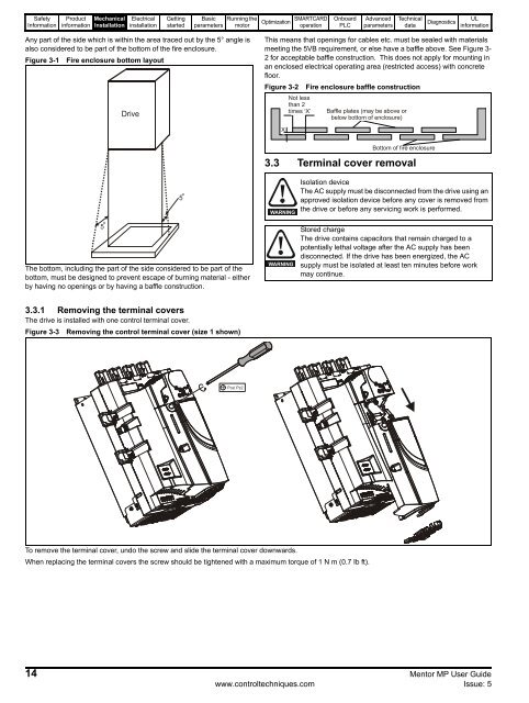
3.3.1 Removing the terminal covers<br />
The drive is installed with one control terminal cover.<br />
Figure 3-3 Removing the control terminal cover (size 1 shown)<br />
Pozi Pz2<br />
To remove the terminal cover, undo the screw and slide the terminal cover downwards.<br />
When replacing the terminal covers the screw should be tightened with a maximum torque of 1 N m (0.7 Ib ft).<br />
14 <strong>Mentor</strong> <strong>MP</strong> User Guide<br />
www.controltechniques.com Issue: 5