Mentor MP
Mentor MP UG Iss 5.book
Mentor MP UG Iss 5.book
- No tags were found...
You also want an ePaper? Increase the reach of your titles
YUMPU automatically turns print PDFs into web optimized ePapers that Google loves.
Safety<br />
Information<br />
Product<br />
information<br />
Mechanical<br />
Installation<br />
Electrical<br />
installation<br />
Getting<br />
started<br />
Basic Running the<br />
parameters motor<br />
Optimization SMARTCARD<br />
operation<br />
Onboard<br />
PLC<br />
Advanced<br />
parameters<br />
Technical<br />
data<br />
Diagnostics<br />
UL<br />
information<br />
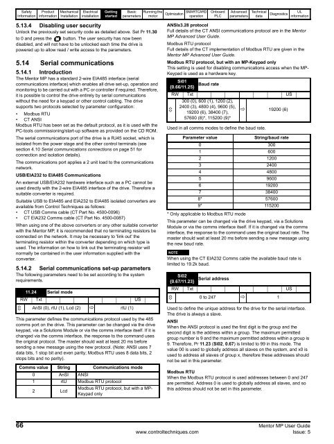
5.13.4 Disabling user security<br />
Unlock the previously set security code as detailed above. Set Pr 11.30<br />
to 0 and press the button. The user security has now been<br />
disabled, and will not have to be unlocked each time the drive is<br />
powered up to allow read / write access to the parameters.<br />
5.14 Serial communications<br />
5.14.1 Introduction<br />
The <strong>Mentor</strong> <strong>MP</strong> has a standard 2-wire EIA485 interface (serial<br />
communications interface) which enables all drive set-up, operation and<br />
monitoring to be carried out with a PC or controller if required. Therefore,<br />
it is possible to control the drive entirely by serial communications<br />
without the need for a keypad or other control cabling. The drive<br />
supports two protocols selected by parameter configuration:<br />
• Modbus RTU<br />
• CT ANSI<br />
Modbus RTU has been set as the default protocol, as it is used with the<br />
PC-tools commissioning/start-up software as provided on the CD ROM.<br />
The serial communications port of the drive is a RJ45 socket, which is<br />
isolated from the power stage and the other control terminals (see<br />
section 4.10 Serial communications connections on page 51 for<br />
connection and isolation details).<br />
The communications port applies a 2 unit load to the communications<br />
network.<br />
USB/EIA232 to EIA485 Communications<br />
An external USB/EIA232 hardware interface such as a PC cannot be<br />
used directly with the 2-wire EIA485 interface of the drive. Therefore a<br />
suitable converter is required.<br />
Suitable USB to EIA485 and EIA232 to EIA485 isolated converters are<br />
available from Control Techniques as follows:<br />
• CT USB Comms cable (CT Part No. 4500-0096)<br />
• CT EIA232 Comms cable (CT Part No. 4500-0087)<br />
When using one of the above converters or any other suitable converter<br />
with the <strong>Mentor</strong> <strong>MP</strong>, it is recommended that no terminating resistors be<br />
connected on the network. It may be necessary to 'link out' the<br />
terminating resistor within the converter depending on which type is<br />
used. The information on how to link out the terminating resistor will<br />
normally be contained in the user information supplied with the<br />
converter.<br />
5.14.2 Serial communications set-up parameters<br />
The following parameters need to be set according to the system<br />
requirements.<br />
11.24 Serial mode<br />
RW Txt US<br />
AnSI (0), rtU (1), Lcd (2) rtU (1)<br />
This parameter defines the communications protocol used by the 485<br />
comms port on the drive. This parameter can be changed via the drive<br />
keypad, via a Solutions Module or via the comms interface itself. If it is<br />
changed via the comms interface, the response to the command uses<br />
the original protocol. The master should wait at least 20 ms before<br />
sending a new message using the new protocol. (Note: ANSI uses 7<br />
data bits, 1 stop bit and even parity; Modbus RTU uses 8 data bits, 2<br />
stops bits and no parity).<br />
Comms value String Communications mode<br />
0 AnSI ANSI<br />
1 rtU Modbus RTU protocol<br />
2 Lcd<br />
Modbus RTU protocol, but with a <strong>MP</strong>-<br />
Keypad only<br />
ANSIx3.28 protocol<br />
Full details of the CT ANSI communications protocol are in the <strong>Mentor</strong><br />
<strong>MP</strong> Advanced User Guide.<br />
Modbus RTU protocol<br />
Full details of the CT implementation of Modbus RTU are given in the<br />
<strong>Mentor</strong> <strong>MP</strong> Advanced User Guide.<br />
Modbus RTU protocol, but with an <strong>MP</strong>-Keypad only<br />
This setting is used for disabling communications access when the <strong>MP</strong>-<br />
Keypad is used as a hardware key.<br />
Si01<br />
{0.66/11.25}<br />
Baud rate<br />
RW Txt US<br />
300 (0), 600 (1), 1200 (2),<br />
2400 (3), 4800 (4), 9600 (5),<br />
<br />
19200 (6), 38400 (7),<br />
19200 (6)<br />
57600 (8)*, 115200 (9)*<br />
Used in all comms modes to define the baud rate.<br />
Parameter value<br />
String/baud rate<br />
0 300<br />
1 600<br />
2 1200<br />
3 2400<br />
4 4800<br />
5 9600<br />
6 19200<br />
7 38400<br />
8* 57600<br />
9* 115200<br />
* Only applicable to Modbus RTU mode<br />
This parameter can be changed via the drive keypad, via a Solutions<br />
Module or via the comms interface itself. If it is changed via the comms<br />
interface, the response to the command uses the original baud rate. The<br />
master should wait at least 20 ms before sending a new message using<br />
the new baud rate.<br />
NOTE<br />
When using the CT EIA232 Comms cable the available baud rate is<br />
limited to 19.2k baud.<br />
Si02<br />
Serial address<br />
{0.67/11.23}<br />
RW Txt US<br />
0 to 247 1<br />
Used to define the unique address for the drive for the serial interface.<br />
The drive is always a slave.<br />
ANSI<br />
When the ANSI protocol is used the first digit is the group and the<br />
second digit is the address within a group. The maximum permitted<br />
group number is 9 and the maximum permitted address within a group is<br />
9. Therefore, Pr 11.23 (Si02, 0.67) is limited to 99 in this mode. The<br />
value 00 is used to globally address all slaves on the system, and x0 is<br />
used to address all slaves of group x, therefore these addresses should<br />
not be set in this parameter.<br />
Modbus RTU<br />
When the Modbus RTU protocol is used addresses between 0 and 247<br />
are permitted. Address 0 is used to globally address all slaves, and so<br />
this address should not be set in this parameter.<br />
66 <strong>Mentor</strong> <strong>MP</strong> User Guide<br />
www.controltechniques.com Issue: 5


