EXPANSION JOINTS
EXPANSION JOINTS - Armaturen-Wolff GmbH
EXPANSION JOINTS - Armaturen-Wolff GmbH

Create successful ePaper yourself
Turn your PDF publications into a flip-book with our unique Google optimized e-Paper software.
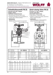
<strong>EXPANSION</strong> <strong>JOINTS</strong>
ARMATUREN-WOLFF • Friedrich H. Wolff GmbH & Co. KG<br />
Oehleckerring 29 • 22419 Hamburg - Germany<br />
Tel. +49 (40) 532 87 30 • Fax +49 (40) 532 87 329<br />
Email: aw@armaturen-wolff.de • Internet: www.armaturen-wolff.de<br />
ARMATUREN<br />
Because of the efforts that are constantly made to improve our products,<br />
the data and characteristics indicated in this publication may be<br />
varied without notice and are therefore not binding for us.
ARMATUREN-WOLFF • Friedrich H. Wolff GmbH & Co. KG<br />
Oehleckerring 29 • 22419 Hamburg - Germany<br />
Tel. +49 (40) 532 87 30 • Fax +49 (40) 532 87 329<br />
Email: aw@armaturen-wolff.de • Internet: www.armaturen-wolff.de<br />
ARMATUREN<br />
Construction<br />
Rubber expansion joints can be devided into two main categories namely the moulded expansion joints and the hand<br />
built ones. AW 1370, 1371, 1372, 1373, 1374, 1375, 1377 series belong to the first category, while the second<br />
category consists of the SPOOL type joints (AW 1376).<br />
The construction is in general as follows:<br />
The inside rubber lining is leak-proof and made of synthetic or natural rubber, depending on the application. This<br />
applies also to the outside rubber cover, of which is the prime function to protect the canvas, between the cover and<br />
the inside lining, from outside damages.<br />
Special polymers can be supplied to resist chemicals, oils, sunlight, acid fumes and ozone.<br />
The pressure supporting canvas consists of fabric and metal reinforcement, as wire or solid rings.<br />
Rubber Qualities<br />
The rubber bellows are available in Neoprene, Butyl, Nitrile, EPDM, Hypalon, Natural rubber and Viton.<br />
rubber quality color band properties<br />
Neoprene<br />
CR<br />
EPDM<br />
Nitril<br />
NBR<br />
Hypalon<br />
CSM<br />
Butyl<br />
IIR<br />
Viton<br />
FPM<br />
PTFE<br />
no color band<br />
red<br />
yellow<br />
green<br />
blue<br />
purple<br />
no colour band<br />
Excellent weather-resistance.<br />
Good oil and gasoline resistance.<br />
Temperature range: -20°C to +70°C.<br />
Outstanding ozone- and sunlight-resistance and suitable for most chemicals,<br />
alkaline waste-water, compressed air (oil free).<br />
Excellent electrical insulation.<br />
Not suitable for oil, gasoline and greases.<br />
Temperature range: -25°C to +130°C.<br />
Very good oil- and gsoline-resistance and suitable for gases, solvents and<br />
greases.<br />
Good abrasion-resistance.<br />
Not applicable to steam and hot water.<br />
Temperature range: -20°C to +90°C.<br />
Outstanding ozone- and sunlight-resistance and suitable for most chemicals.<br />
Good oil- and gasoline resistance.<br />
Temperature range: -25°C to +80°C.<br />
Very good heat- and weather-resistance, suitable for alkaline waste-water,<br />
chemicals and compressed air (oil free)<br />
Temperature range: -25°C to +150°C.<br />
Suitable for chemicals, oil, gasoline and solvents.<br />
Not suitable for chlorines and ketones.<br />
Temperature range: -10°C to +180°C.<br />
Outstanding resistance for all media, with the exception of alkali metals at<br />
melting point and amis´des formed from the reaction of a carboxylic acid<br />
with an amine.<br />
Temperature range: -50°C to +230°C.
ARMATUREN-WOLFF • Friedrich H. Wolff GmbH & Co. KG<br />
Oehleckerring 29 • 22419 Hamburg - Germany<br />
Tel. +49 (40) 532 87 30 • Fax +49 (40) 532 87 329<br />
Email: aw@armaturen-wolff.de • Internet: www.armaturen-wolff.de<br />
ARMATUREN<br />
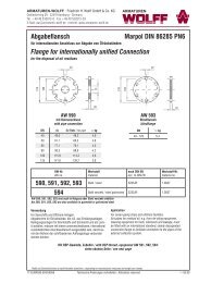
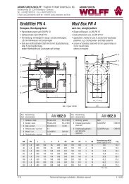
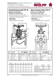
Gummi-Kompensator<br />
Expansion Joint<br />
drehbare, galvanisierte Stahlflansche<br />
floating galvanized steel flanges<br />
beide Enden mit gehärtetem Stützring<br />
both ends by hardened steel wire rings<br />
Balg-Verstärkung durch Wicklungen aus Nylonfäden bellow reinforcement by Nylon tire cords<br />
● Flansche nach DIN PN 10/16 ● flanges acc. to DIN PN 10/16<br />
L<br />
α°<br />
-x<br />
+x<br />
y<br />
AW-Nr. Pos. Bezeichnung Werkstoff Werkstoff nach DIN EN Werkstoff-Nr.<br />
AW no. item denomination material material acc. to DIN EN material no.<br />
1370<br />
1 Flansche / flanges galvanisierter Stahl / galvanized steel S235JR 1.0037<br />
2 Balg / bellow NBR (gelb / yellow) oder / or EPDM (rot / red)<br />
DN inch L<br />
axial<br />
-x<br />
axial<br />
+x<br />
radial<br />
y<br />
α°<br />
max. Druck<br />
max. pressure<br />
bar (PSI)<br />
bis / up to 80°C<br />
Vakuum<br />
mm Hg<br />
(in Hg)<br />
≈ kg<br />
32 1 1/ 4 " 95 8 4 8 15° 16 (225) 660 (26) 2,5<br />
40 1 1/ 2 " 95 8 4 4 15° 16 (225) 660 (26) 2,9<br />
50 2" 105 8 5 8 15° 16 (225) 660 (26) 3,5<br />
65 2 1/ 2 " 115 12 6 10 15° 16 (225) 660 (26) 5,0<br />
80 3" 130 12 6 10 15° 16 (225) 660 (26) 5,7<br />
100 4" 135 18 10 12 15° 16 (225) 660 (26) 6,0<br />
125 5" 170 18 10 12 15° 16 (225) 660 (26) 8,0<br />
150 6" 180 18 10 12 15° 16 (225) 660 (26) 10,9<br />
200 8" 205 25 14 22 15° 16 (225) 660 (26) 15,1<br />
250 10" 240 25 14 22 15° 16 (225) 660 (26) 18,5<br />
300 12" 260 25 14 22 15° 16 (225) 660 (26) 24,2<br />
350 14" 265 25 16 22 15° 10 (150) 660 (26) -<br />
400 16" 265 25 16 22 15° 7 (100) 660 (26) -<br />
450 18" 265 25 16 22 15° 7 (100) 660 (26) -<br />
500 20" 265 25 16 22 15° 7 (100) 660 (26) -<br />
600 24" 265 25 16 22 15° 7 (100) 660 (26) -<br />
700 28" 265 25 16 22 15° 7 (100) 660 (26) -<br />
800 32" 265 25 16 22 15° 7 (100) 660 (26) -<br />
900 36" 265 25 16 22 15° 7 (100) 660 (26) -<br />
1000 40" 265 25 16 22 15° 7 (100) 660 (26) -<br />
1200 48" 265 25 16 22 15° 7 (100) 660 (26)<br />
Bei einer Betriebstemperatur von über 80°C müsssen der max. zulässige<br />
Betriebsdruck und die max. Verformung mit den folgenden Faktoren bestimmt<br />
werden:<br />
The max. allowable pressure and movements must be adjusted by one of the<br />
factors below at operating temperatures over 80°C:<br />
85°C 90°C 95°C 100°C >100<br />
0,92 0,83 0,75 0,67 0,60<br />
max. zulässige Temperatur / max. allowable temperature: 105°C<br />
Berstdruck / Burst Pressure<br />
60 bar Größe / size DN 32 - DN 300<br />
40 bar Größe / size DN 350<br />
24 bar Größe / size DN 400 - DN 1200<br />
Auf Anfrage / on request<br />
• Balg aus / bellow out of<br />
CR (-), CSM (grün / green), IIR (blau / blue), NBR (gelb / yellow)<br />
FPM (Violett / purple), PTFE (-)<br />
• für starkes Vakuum / for high vacuum:<br />
Vakuum-Stützring oder -spirale / vacuum-ring or -spiral<br />
Maße und Gewichte können je nach Hersteller abweichen / depending on manufacturers measures and weight can change<br />
0909/AW1370/50407 Technische Änderungen vorbehalten / Alterations reserved T- 01.00
ARMATUREN-WOLFF • Friedrich H. Wolff GmbH & Co. KG<br />
Oehleckerring 29 • 22419 Hamburg - Germany<br />
Tel. +49 (40) 532 87 30 • Fax +49 (40) 532 87 329<br />
Email: aw@armaturen-wolff.de • Internet: www.armaturen-wolff.de<br />
ARMATUREN<br />
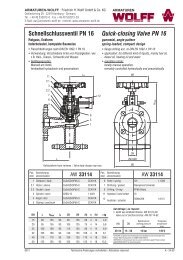
Gummi-Kompensator<br />
drehbare, galvanisierte Stahlflansche<br />
beide Enden mit gehärtetem Stützring<br />
Balg-Verstärkung durch Wicklungen aus Nylonfäden<br />
Expansion Joint<br />
floating galvanized steel flanges<br />
both ends by hardened steel wire rings<br />
bellow reinforcement by Nylon tire cords<br />
● Flansche nach DIN PN 10/16 ● flanges acc. to DIN PN 10/16<br />
L<br />
-x<br />
+x<br />
α°<br />
y<br />
AW-Nr. Pos. Bezeichnung Werkstoff Werkstoff nach DIN EN Werkstoff-Nr.<br />
AW no. item denomination material material acc. to DIN EN material no.<br />
1371<br />
1 Flansche / flanges galvanisierter Stahl / galvanized steel S235JR 1.0037<br />
2 Balg / bellow NBR (gelb / yellow) oder / or EPDM (rot / red)<br />
DN inch L<br />
axial<br />
-x<br />
axial<br />
+x<br />
radial<br />
y<br />
α°<br />
max. Druck<br />
max. pressure<br />
bar (PSI)<br />
bis / up to 80°C<br />
Vakuum<br />
mm Hg<br />
(in Hg)<br />
32 1 1/ 4 " 130 30 20 20 35° 16 (225) 660 (26)<br />
40 1 1/ 2 " 130 30 20 20 35° 16 (225) 660 (26)<br />
50 2" 130 30 20 20 35° 16 (225) 660 (26)<br />
65 2 1/ 2 " 130 30 20 20 35° 16 (225) 660 (26)<br />
80 3" 130 30 20 20 35° 16 (225) 660 (26)<br />
100 4" 130 30 20 20 25° 16 (225) 660 (26)<br />
125 5" 130 30 20 20 25° 16 (225) 660 (26)<br />
150 6" 130 30 20 20 15° 16 (225) 660 (26)<br />
200 8" 130 30 20 20 15° 16 (225) 660 (26)<br />
250 10" 130 30 20 20 10° 10 (150) 660 (26)<br />
300 12" 130 30 20 20 10° 10 (150) 660 (26)<br />
Bei einer Betriebstemperatur von über 80°C müsssen der max. zulässige<br />
Betriebsdruck und die max. Verformung mit den folgenden Faktoren bestimmt<br />
werden:<br />
The max. allowable pressure and movements must be adjusted by one of the<br />
factors below at operating temperatures over 80°C:<br />
85°C 90°C 95°C 100°C >100<br />
0,92 0,83 0,75 0,67 0,60<br />
max. zulässige Temperatur / max. allowable temperature: 105°C<br />
Berstdruck / Burst Pressure<br />
60 bar Größe / size DN 32 - DN 200<br />
40 bar Größe / size DN 250 - DN 300<br />
Auf Anfrage / on request<br />
• Balg aus / bellow out of<br />
CR (-), CSM (grün / green), IIR (blau / blue), NBR (gelb / yellow)<br />
FPM (Violett / purple), PTFE (-)<br />
• für starkes Vakuum / for high vacuum:<br />
Vakuum-Stützring oder -spirale / vacuum-ring or -spiral<br />
Maße und Gewichte können je nach Hersteller abweichen / depending on manufacturers measures and weight can change<br />
0909/AW1371/50407 Technische Änderungen vorbehalten / Alterations reserved T- 02.00
ARMATUREN-WOLFF • Friedrich H. Wolff GmbH & Co. KG<br />
Oehleckerring 29 • 22419 Hamburg - Germany<br />
Tel. +49 (40) 532 87 30 • Fax +49 (40) 532 87 329<br />
Email: aw@armaturen-wolff.de • Internet: www.armaturen-wolff.de<br />
ARMATUREN<br />
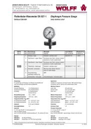
Gummi-Kompensator<br />
drehbare, galvanisierte Stahlflansche<br />
beide Enden mit gehärtetem Stützring<br />
Balg-Verstärkung durch Wicklungen aus Nylonfäden<br />
● Flansche nach DIN PN 10/16 mit Gewindebohrungen<br />
Expansion Joint<br />
floating galvanized steel flanges<br />
both ends by hardened steel wire rings<br />
bellow reinforcement by Nylon tire cords<br />
● flanges acc. to DIN PN 10/16 with threaded holes<br />
L<br />
-x +x<br />
α°<br />
y<br />
AW-Nr. Pos. Bezeichnung Werkstoff Werkstoff nach DIN EN Werkstoff-Nr.<br />
AW no. item denomination material material acc. to DIN EN material no.<br />
1372<br />
1 Flansche / flanges galvanisierter Stahl / galvanized steel S235JR 1.0037<br />
2 Balg / bellow NBR (gelb / yellow) oder / or EPDM (rot / red)<br />
DN inch L<br />
axial<br />
-x<br />
axial<br />
+x<br />
radial<br />
y<br />
α°<br />
max. Druck<br />
max. pressure<br />
bar (PSI)<br />
bis / up to 80°C<br />
Vakuum<br />
mm Hg<br />
(in Hg)<br />
32 1 1/ 4 " 105 30 20 15 7,5° 16 (225) 660 (26)<br />
40 1 1/ 2 " 105 30 20 15 7,5° 16 (225) 660 (26)<br />
50 2" 105 30 20 15 7,5° 16 (225) 660 (26)<br />
65 2 1/ 2 " 105 30 20 15 7,5° 16 (225) 660 (26)<br />
80 3" 105 30 20 15 7,5° 16 (225) 660 (26)<br />
100 4" 105 30 20 15 7,5° 16 (225) 660 (26)<br />
125 5" 105 30 20 15 7,5° 16 (225) 660 (26)<br />
150 6" 105 30 20 15 7,5° 16 (225) 660 (26)<br />
200 8" 105 30 20 15 5° 16 (225) 660 (26)<br />
250 10" 105 30 20 15 5° 16 (225) 660 (26)<br />
300 12" 105 30 20 15 5° 16 (225) 660 (26)<br />
Bei einer Betriebstemperatur von über 80°C müsssen der max. zulässige<br />
Betriebsdruck und die max. Verformung mit den folgenden Faktoren bestimmt<br />
werden:<br />
The max. allowable pressure and movements must be adjusted by one of the<br />
factors below at operating temperatures over 80°C:<br />
85°C 90°C 95°C 100°C >100<br />
0,92 0,83 0,75 0,67 0,60<br />
max. zulässige Temperatur / max. allowable temperature: 105°C<br />
Berstdruck / Burst Pressure<br />
60 bar Größe / size DN 32 - DN 200<br />
40 bar Größe / size DN 250 - DN 300<br />
Auf Anfrage / on request<br />
• Balg aus / bellow out of<br />
CR (-), CSM (grün / green), IIR (blau / blue), NBR (gelb / yellow)<br />
FPM (Violett / purple), PTFE (-)<br />
• für starkes Vakuum / for high vacuum:<br />
Vakuum-Stützring oder -spirale / vacuum-ring or -spiral<br />
Maße und Gewichte können je nach Hersteller abweichen / depending on manufacturers measures and weight can change<br />
0909/AW1372/50407 Technische Änderungen vorbehalten / Alterations reserved T- 03.00
ARMATUREN-WOLFF • Friedrich H. Wolff GmbH & Co. KG<br />
Oehleckerring 29 • 22419 Hamburg - Germany<br />
Tel. +49 (40) 532 87 30 • Fax +49 (40) 532 87 329<br />
Email: aw@armaturen-wolff.de • Internet: www.armaturen-wolff.de<br />
ARMATUREN<br />
Gummi-Kompensator<br />
drehbare, galvanisierte Stahlflansche<br />
beide Enden mit gehärtetem Stützring<br />
Balg-Verstärkung durch Wicklungen aus Nylonfäden<br />
Expansion Joint<br />
floating galvanized steel flanges<br />
both ends by hardened steel wire rings<br />
bellow reinforcement by Nylon tire cords<br />
● Flansche nach DIN PN 10/16 ● flanges acc. to DIN PN 10/16<br />
L<br />
-x<br />
+x<br />
α°<br />
y<br />
AW-Nr. Pos. Bezeichnung Werkstoff Werkstoff nach DIN EN Werkstoff-Nr.<br />
AW no. item denomination material material acc. to DIN EN material no.<br />
1373<br />
1 Flansche / flanges galvanisierter Stahl / galvanized steel S235JR 1.0037<br />
2 Balg / bellow NBR (gelb / yellow) oder / or EPDM (rot / red)<br />
DN inch L<br />
axial<br />
-x<br />
axial<br />
+x<br />
radial<br />
y<br />
α°<br />
max. Druck<br />
max. pressure<br />
bar (PSI)<br />
bis / up to 80°C<br />
Vakuum<br />
mm Hg<br />
(in Hg)<br />
32 1 1/ 4 " 6" 1/ 2 " 3/ 8 " 1/ 2 " 15° 16 (225) 660 (26)<br />
40 1 1/ 2 " 6" 1/ 2 " 3/ 8 " 1/ 2 " 15° 16 (225) 660 (26)<br />
50 2" 6" 1/ 2 " 3/ 8 " 1/ 2 " 15° 16 (225) 660 (26)<br />
65 2 1/ 2 " 6" 1/ 2 " 3/ 8 " 1/ 2 " 15° 16 (225) 660 (26)<br />
80 3" 6" 1/ 2 " 3/ 8 " 1/ 2 " 15° 16 (225) 660 (26)<br />
100 4" 6" 5/ 8 " 3/ 8 " 1/ 2 " 15° 16 (225) 660 (26)<br />
125 5" 6" 5/ 8 " 3/ 8 " 1/ 2 " 15° 16 (225) 660 (26)<br />
150 6" 6" 5/ 8 " 3/ 8 " 1/ 2 " 15° 16 (225) 660 (26)<br />
200 8" 6" 5/ 8 " 3/ 8 " 1/ 2 " 15° 16 (225) 660 (26)<br />
250 10" 8" 3/ 4 " 1/ 2 " 3/ 4 " 15° 16 (225) 660 (26)<br />
300 12" 8" 3/ 4 " 1/ 2 " 3/ 4 " 15° 16 (225) 660 (26)<br />
350 14" 8" 3/ 4 " 1/ 2 " 3/ 4 " 15° 10 (150) 660 (26)<br />
400 16" 8" 3/ 4 " 1/ 2 " 3/ 4 " 15° 7 (100) 660 (26)<br />
450 18" 8" 3/ 4 " 1/ 2 " 3/ 4 " 15° 7 (100) 660 (26)<br />
500 20" 8" 3/ 4 " 1/ 2 " 3/ 4 " 15° 7 (100) 660 (26)<br />
Bei einer Betriebstemperatur von über 80°C müsssen der max. zulässige<br />
Betriebsdruck und die max. Verformung mit den folgenden Faktoren bestimmt<br />
werden:<br />
The max. allowable pressure and movements must be adjusted by one of the<br />
factors below at operating temperatures over 80°C:<br />
85°C 90°C 95°C 100°C >100<br />
0,92 0,83 0,75 0,67 0,60<br />
max. zulässige Temperatur / max. allowable temperature: 105°C<br />
Berstdruck / Burst Pressure<br />
60 bar Größe / size DN 32 - DN 300<br />
40 bar Größe / size DN 350<br />
24 bar Größe / size DN 400 - DN 500<br />
Speziell auf den nordamerikanischen Markt abgestimmt.<br />
Attuned to the USA market.<br />
Auf Anfrage / on request<br />
• Balg aus / bellow out of<br />
CR (-), CSM (grün / green), IIR (blau / blue), NBR (gelb / yellow)<br />
FPM (Violett / purple), PTFE (-)<br />
• für starkes Vakuum / for high vacuum:<br />
Vakuum-Stützring oder -spirale / vacuum-ring or -spiral<br />
Maße und Gewichte können je nach Hersteller abweichen / depending on manufacturers measures and weight can change<br />
0909/AW1373/50407 Technische Änderungen vorbehalten / Alterations reserved T- 04.00
ARMATUREN-WOLFF • Friedrich H. Wolff GmbH & Co. KG<br />
Oehleckerring 29 • 22419 Hamburg - Germany<br />
Tel. +49 (40) 532 87 30 • Fax +49 (40) 532 87 329<br />
Email: aw@armaturen-wolff.de • Internet: www.armaturen-wolff.de<br />
ARMATUREN<br />
Gummi-Kompensator<br />
Expansion Joint<br />
drehbare, galvanisierte Stahlflansche<br />
floating galvanized steel flanges<br />
beide Enden mit gehärtetem Stützring<br />
both ends by hardened steel wire rings<br />
Doppelbalg für größere zul. Längenänderungen<br />
double sphere joints for larger movements<br />
Balg-Verstärkung durch Wicklungen aus Nylonfäden bellow reinforcement by Nylon tire cords<br />
● Flansche nach DIN PN 10/16 ● flanges acc. to DIN PN 10/16<br />
L<br />
α°<br />
-x<br />
+x<br />
y<br />
AW-Nr. Pos. Bezeichnung Werkstoff Werkstoff nach DIN EN Werkstoff-Nr.<br />
AW no. item denomination material material acc. to DIN EN material no.<br />
1374<br />
1 Flansche / flanges galvanisierter Stahl / galvanized steel S235JR 1.0037<br />
2 Balg / bellow NBR (gelb / yellow) oder / or EPDM (rot / red)<br />
DN inch L<br />
axial<br />
-x<br />
axial<br />
+x<br />
radial<br />
y<br />
α°<br />
max. Druck<br />
max. pressure<br />
bar (PSI)<br />
bis / up to 80°C<br />
Vakuum<br />
mm Hg<br />
(in Hg)<br />
25 1" 120 30 15 25 25° 16 (225) 660 (26)<br />
32 1 1/ 4 " 175 50 25 40 40° 16 (225) 660 (26)<br />
40 1 1/ 2 " 175 50 25 40 40° 16 (225) 660 (26)<br />
50 2" 175 50 25 40 40° 16 (225) 660 (26)<br />
65 2 1/ 2 " 175 50 25 40 40° 16 (225) 660 (26)<br />
80 3" 175 50 25 40 40° 16 (225) 660 (26)<br />
100 4" 225 55 30 40 35° 16 (225) 660 (26)<br />
125 5" 225 55 30 40 35° 16 (225) 660 (26)<br />
150 6" 225 55 30 49 35° 16 (225) 660 (26)<br />
200 8" 325 65 30 35 30° 16 (225) 660 (26)<br />
250 10" 325 65 30 35 30° 16 (225) 660 (26)<br />
300 12" 325 65 30 35 30° 16 (225) 660 (26)<br />
350 14" 350 40 30 30 20° 10 (150) 660 (26)<br />
400 16" 350 40 30 30 20° 7 (100) 660 (26)<br />
450 18" 350 40 30 30 20° 7 (100) 400 (16)<br />
500 20" 350 40 30 30 20° 7 (100) 400 (16)<br />
600 24" 350 40 30 30 20° 7 (100) 400 (16)<br />
Bei einer Betriebstemperatur von über 80°C müsssen der max. zulässige<br />
Betriebsdruck und die max. Verformung mit den folgenden Faktoren bestimmt<br />
werden:<br />
The max. allowable pressure and movements must be adjusted by one of the<br />
factors below at operating temperatures over 80°C:<br />
85°C 90°C 95°C 100°C >100<br />
0,92 0,83 0,75 0,67 0,60<br />
max. zulässige Temperatur / max. allowable temperature: 105°C<br />
Berstdruck / Burst Pressure<br />
60 bar Größe / size DN 32 - DN 200<br />
24 bar Größe / size DN 250 - DN 450<br />
Auf Anfrage / on request<br />
• Balg aus / bellow out of<br />
CR (-), CSM (grün / green), IIR (blau / blue), NBR (gelb / yellow)<br />
FPM (Violett / purple), PTFE (-)<br />
• für starkes Vakuum / for high vacuum:<br />
Vakuum-Stützring oder -spirale / vacuum-ring or -spiral<br />
Maße und Gewichte können je nach Hersteller abweichen / depending on manufacturers measures and weight can change<br />
0909/AW1374/50407 Technische Änderungen vorbehalten / Alterations reserved T- 05.00
ARMATUREN-WOLFF • Friedrich H. Wolff GmbH & Co. KG<br />
Oehleckerring 29 • 22419 Hamburg - Germany<br />
Tel. +49 (40) 532 87 30 • Fax +49 (40) 532 87 329<br />
Email: aw@armaturen-wolff.de • Internet: www.armaturen-wolff.de<br />
ARMATUREN<br />
Gummi-Kompensator<br />
Expansion Joint<br />
bewegliche Flansche<br />
floating flanges<br />
Balg-Verstärkung durch Wicklungen aus Nylonfäden bellow reinforcement by Nylon tire cords<br />
● Flansche nach DIN PN 10/16 ● flanges acc. to DIN PN 10/16<br />
L<br />
-x<br />
+x<br />
α°<br />
y<br />
AW-Nr. Pos. Bezeichnung Werkstoff Werkstoff nach DIN EN Werkstoff-Nr.<br />
AW no. item denomination material material acc. to DIN EN material no.<br />
1375<br />
1 Flansche / flanges Sphäroguss / nodular cast iron<br />
2 Balg / bellow NBR (gelb / yellow) oder / or EPDM (rot / red)<br />
DN inch L<br />
axial<br />
-x<br />
axial<br />
+x<br />
radial<br />
y<br />
α°<br />
max. Druck<br />
max. pressure<br />
bar (PSI)<br />
bis / up to 80°C<br />
Vakuum<br />
mm Hg<br />
(in Hg)<br />
50 2" 150 30 20 20 35° 10 (150) 380 (15)<br />
65 2 1/ 2 " 150 30 20 20 30° 10 (150) 380 (15)<br />
80 3" 150 30 20 20 30° 10 (150) 380 (15)<br />
100 4" 150 30 20 20 25° 10 (150) 380 (15)<br />
125 5" 150 30 20 20 25° 10 (150) 380 (15)<br />
150 6" 150 30 20 25 20° 10 (150) 380 (15)<br />
200 8" 150 30 20 25 20° 10 (150) 380 (15)<br />
250 10" 200 30 20 25 15° 10 (150) 380 (15)<br />
300 12" 200 30 20 25 15° 10 (150) 380 (15)<br />
350 14" 200 50 23 25 12° 9 (130) 255 (10)<br />
400 16" 200 50 23 25 12° 71/ 2 (110) 255 (10)<br />
450 18" 200 50 23 25 9° 71/ 2 (110) 255 (10)<br />
500 20" 200 50 23 25 9° 71/ 2 (110) 255 (10)<br />
600 24" 250 55 25 25 9° 7 (100) 255 (10)<br />
Bei einer Betriebstemperatur von über 80°C müsssen der max. zulässige<br />
Betriebsdruck und die max. Verformung mit den folgenden Faktoren bestimmt<br />
werden:<br />
The max. allowable pressure and movements must be adjusted by one of the<br />
factors below at operating temperatures over 80°C:<br />
85°C 90°C 95°C 100°C >100<br />
0,92 0,83 0,75 0,67 0,60<br />
max. zulässige Temperatur / max. allowable temperature: 105°C<br />
Berstdruck / Burst Pressure<br />
60 bar Größe / size DN 50 - DN 200<br />
24 bar Größe / size DN 250 - DN 450<br />
Auf Anfrage / on request<br />
• Balg aus / bellow out of<br />
CR (-), CSM (grün / green), IIR (blau / blue), NBR (gelb / yellow)<br />
FPM (Violett / purple), PTFE (-)<br />
• für starkes Vakuum / for high vacuum:<br />
Vakuum-Stützring oder -spirale / vacuum-ring or -spiral<br />
Maße und Gewichte können je nach Hersteller abweichen / depending on manufacturers measures and weight can change<br />
0909/AW1375/50407 Technische Änderungen vorbehalten / Alterations reserved T- 06.00
ARMATUREN-WOLFF • Friedrich H. Wolff GmbH & Co. KG<br />
Oehleckerring 29 • 22419 Hamburg - Germany<br />
Tel. +49 (40) 532 87 30 • Fax +49 (40) 532 87 329<br />
Email: aw@armaturen-wolff.de • Internet: www.armaturen-wolff.de<br />
ARMATUREN<br />
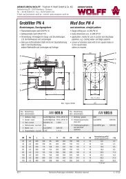
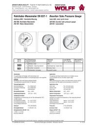
Gummi-Kompensator<br />
Expansion Joint<br />
bewegliche, galvanisierte Flansche<br />
floating galvanized flanges<br />
Handgefertigt mit bis zu vier Bögen (SPOOL-Typ)<br />
hand built with one up to four arches (SPOOL type)<br />
Verstärkt durch Kunstfaser u. Spiral-Stahldraht /Stahlstreben reinforced by synthetic and spiral steel / steel bars<br />
● Flansche nach DIN PN 10/16 ● flanges acc. to DIN PN 10/16<br />
α°<br />
L<br />
-x +x<br />
y<br />
AW-Nr. Pos. Bezeichnung Werkstoff Werkstoff nach DIN EN Werkstoff-Nr.<br />
AW no. item denomination material material acc. to DIN EN material no.<br />
1376<br />
1 Flansche / flanges galvanisierter Stahl / galvanized steel S235JR 1.0037<br />
2 Balg / bellow NBR (gelb / yellow) oder / or EPDM (rot / red)<br />
DN inch L<br />
axial<br />
-x<br />
axial<br />
+x<br />
radial<br />
y<br />
α°<br />
max. Druck<br />
max. pressure<br />
bar (PSI)<br />
bis / up to 80°C<br />
1000 40" 255 40 20 15 1,5° 4 (60)<br />
1050 42" 305 40 20 20 1,5° 4 (60)<br />
1100 44" 305 40 20 20 1,5° 4 (60)<br />
1200 48" 305 40 20 20 1,5° 4 (60)<br />
1300 50 305 40 20 20 1,3° 4 (60)<br />
1400 54" 305 40 20 20 1,3° 4 (60)<br />
1450 56" 305 40 20 20 1,3° 4 (60)<br />
1500 60" 305 40 20 20 1,0° 4 (60)<br />
1600 62" 305 40 20 20 1,0° 31/ 2 (50)<br />
1700 66" 305 40 20 20 1,0° 31/ 2 (50)<br />
1800 72" 305 40 20 20 0,9° 31/ 2 (50)<br />
2000 78" 305 40 20 20 0,9° 31/ 2 (50)<br />
2100 84" 305 40 20 20 0,8° 31/ 2 (50)<br />
2300 90" 305 40 20 20 0,8° 31/ 2 (50)<br />
2400 96" 305 40 20 20 0,8° 31/ 2 (50)<br />
2450 98" 305 60 25 30 0,6° 2 (30)<br />
2500 100" 305 60 25 30 0,6° 2 (30)<br />
2600 102" 305 60 25 30 0,6° 2 (30)<br />
2700 108" 305 60 25 30 0,4° 13/ 4 (25)<br />
3000 120" 305 60 25 30 0,4° 13/ 4 (25)<br />
3350 132" 305 60 25 30 0,3° 13/ 4 (25)<br />
3650 144" 305 60 25 30 0,1° 13/ 4 (25)<br />
Bei einer Betriebstemperatur von über 80°C müsssen der max. zulässige<br />
Betriebsdruck und die max. Verformung mit den folgenden Faktoren bestimmt<br />
werden:<br />
The max. allowable pressure and movements must be adjusted by one of the<br />
factors below at operating temperatures over 80°C:<br />
85°C 90°C 95°C 100°C >100<br />
0,92 0,83 0,75 0,67 0,60<br />
max. zulässige Temperatur / max. allowable temperature: 105°C<br />
Typ SA<br />
Typ DA<br />
Typ TA<br />
Typ MA<br />
mit einem Bogen / with one arch<br />
mit zwei Bögen / with two arches<br />
mit drei Bögen / with three arches<br />
mit vier Bögen / with four arches<br />
Auf Anfrage / on request<br />
• Balg aus / bellow out of<br />
CR (-), CSM (grün / green), IIR (blau / blue), NBR (gelb / yellow)<br />
FPM (Violett / purple), PTFE (-)<br />
• für starkes Vakuum / for high vacuum:<br />
Vakuum-Stützring oder -spirale / vacuum-ring or -spiral<br />
Maße und Gewichte können je nach Hersteller abweichen / depending on manufacturers measures and weight can change<br />
0909/AW1376/50407 Technische Änderungen vorbehalten / Alterations reserved T- 07.00
ARMATUREN-WOLFF • Friedrich H. Wolff GmbH & Co. KG<br />
Oehleckerring 29 • 22419 Hamburg - Germany<br />
Tel. +49 (40) 532 87 30 • Fax +49 (40) 532 87 329<br />
Email: aw@armaturen-wolff.de • Internet: www.armaturen-wolff.de<br />
ARMATUREN<br />
Gummi-Verbinder<br />
Anschlußstücke mit Überwurfmuttern<br />
Doppelbalg aus Nitril-Kautschuk<br />
Balg-Verstärkung durch Wicklungen aus Nylonfäden<br />
● Innengewinde nach BSP<br />
Rubber Connector<br />
ends with union nuts<br />
double sphere in nitrile rubber<br />
bellow reinforcement by Nylon tire cords<br />
● female thread acc. to BSP<br />
L<br />
AW-Nr. Pos. Bezeichnung Werkstoff Werkstoff nach DIN EN Werkstoff-Nr.<br />
AW no. item denomination material material acc. to DIN EN material no.<br />
1377<br />
1 Anschlüsse / unions Sphäroguss / nodular cast iron<br />
2 Balg / bellow NBR<br />
DN inch L<br />
axial<br />
-x<br />
axial<br />
+x<br />
radial<br />
y<br />
α°<br />
max. Druck<br />
max. pressure<br />
bar (PSI)<br />
bis / up to 80°C<br />
Vakuum<br />
mm Hg<br />
(in Hg)<br />
20 3/ 4 " 200 22 6 22 32° 10 (150) 660 (26)<br />
25 1" 200 22 6 22 25° 10 (150) 660 (26)<br />
32 1 1/ 4 " 200 22 6 22 25° 10 (150) 660 (26)<br />
Bei einer Betriebstemperatur von über 80°C müsssen der max. zulässige<br />
Betriebsdruck und die max. Verformung mit den folgenden Faktoren bestimmt<br />
werden:<br />
The max. allowable pressure and movements must be adjusted by one of the<br />
factors below at operating temperatures over 80°C:<br />
85°C 90°C 95°C 100°C >100<br />
0,92 0,83 0,75 0,67 0,60<br />
40 1 1/ 2 " 200 22 6 22 20° 10 (150) 660 (26)<br />
Berstdruck / burst pressure:<br />
60 bar<br />
50 2" 200 22 6 22 15° 10 (150) 660 (26)<br />
65 2 1/ 2 " 240 22 6 22 12° 10 (150) 660 (26)<br />
Auf Anfrage / on request<br />
• Balg aus / bellow out of<br />
CR (-), CSM (grün / green), IIR (blau / blue), NBR (gelb / yellow)<br />
FPM (Violett / purple), PTFE (-)<br />
Maße und Gewichte können je nach Hersteller abweichen / depending on manufacturers measures and weight can change<br />
0909/AW1377/50407 Technische Änderungen vorbehalten / Alterations reserved T- 08.00
ARMATUREN-WOLFF • Friedrich H. Wolff GmbH & Co. KG<br />
Oehleckerring 29 • 22419 Hamburg - Germany<br />
Tel. +49 (40) 532 87 30 • Fax +49 (40) 532 87 329<br />
Email: aw@armaturen-wolff.de • Internet: www.armaturen-wolff.de<br />
ARMATUREN<br />
Overall Free Lengths<br />
size<br />
mm (in)<br />
moulded expansion joints hand built SPOOL type mould. ex. j.<br />
AW 1370 AW 1371 AW 1372 AW 1373 AW 1374 AW 1375<br />
AW 1376<br />
SA DA TA MA<br />
20 (1") - - - - - - - - - - 200<br />
25 (1") - 130 105 - 120 - - - - - 200<br />
32 (11/ 4 ") 95 130 105 150 175 - - - - - 200<br />
40 (11/ 2 ") 95 130 105 150 175 - - - - - 200<br />
50 (2") 105 130 105 150 175 150 150 250 350 450 200<br />
65 (21/ 2 ") 115 130 105 150 175 150 150 250 350 450 240<br />
80 (3") 130 130 105 150 175 150 150 250 350 450 -<br />
100 (4") 135 130 105 150 225 150 150 250 350 450 -<br />
125 (5") 170 130 105 150 225 150 150 250 350 450 -<br />
150 (6") 180 130 105 150 225 150 150 250 350 450 -<br />
200 (8") 205 130 105 150 325 150 150 250 350 450 -<br />
250 (10") 240 130 105 200 325 200 200 300 400 500 -<br />
300 (12") 260 130 105 200 325 200 200 300 400 500 -<br />
350 (14") 265 - - 200 350 200 200 300 400 500 -<br />
400 (16") 265 - - 200 350 200 200 300 400 500 -<br />
450 (18") 265 - - 200 350 200 200 300 400 500 -<br />
500 (20") 265 - - 200 - 200 200 300 400 500 -<br />
600 (24") 265 - - - - 250 250 350 450 550 -<br />
700 (28") 265 - - - - - 250 350 450 550 -<br />
800 (32") 265 - - - - - 250 350 450 550 -<br />
900 (36") 265 - - - - - 250 350 450 550 -<br />
1000 (40") 265 - - - - - 250 350 450 550 -<br />
1100 (44") 265 - - - - - 300 400 500 600 -<br />
1200 (48") 265 - - - - - 300 400 500 600 -<br />
1300 (50") - - - - - - 300 400 500 600 -<br />
1400 (54") - - - - - - 300 400 500 600 -<br />
1450 (56") - - - - - - 300 400 500 600 -<br />
1500 (60") - - - - - - 300 400 500 600 -<br />
1600 (62") - - - - - - 300 400 500 600 -<br />
1700 (66") - - - - - - 300 400 500 600 -<br />
1800 (72") - - - - - - 300 400 500 600 -<br />
2000 (78") - - - - - - 300 400 500 600 -<br />
2100 (84") - - - - - - 300 400 500 600 -<br />
2300 (90") - - - - - - 300 400 500 600 -<br />
2400 (96") - - - - - - 300 400 500 600 -<br />
2450 (98") - - - - - - 300 400 500 600 -<br />
2500 (100") - - - - - - 300 400 500 600 -<br />
2600 (102") - - - - - - 300 400 500 600 -<br />
2700 (108") - - - - - - 300 400 500 600 -<br />
3000 (120") - - - - - - 300 400 500 600 -<br />
3350 (132") - - - - - - 300 400 500 600 -<br />
3650 (144") - - - - - - 300 400 500 600 -<br />
AW 1377
ARMATUREN-WOLFF • Friedrich H. Wolff GmbH & Co. KG<br />
Oehleckerring 29 • 22419 Hamburg - Germany<br />
Tel. +49 (40) 532 87 30 • Fax +49 (40) 532 87 329<br />
Email: aw@armaturen-wolff.de • Internet: www.armaturen-wolff.de<br />
ARMATUREN<br />
Physical and Chemical Properties of Elastomers<br />
Elastomers Neoprene Nat. Rubber Butyl Nitrile Hypalon EPDM Viton Silicone<br />
ASTM D-20000/SAE J-200 BC AA AA BF CE BA HK GE<br />
ANSI/ASTM D1418-77 CR IR IIR NBR CSM EPDM FKM SI<br />
alkali, conc. 0 X 4 0 4 6 0 0<br />
animal & veg. oil 4 X 5 5 4 5 6 5<br />
chemicals 3 3 6 3 6 6 6 5<br />
water 4 5 5 4 5 5 5 5<br />
Oxygenated Hydro 1 4 4 0 1 6 0 2<br />
lacquers 0 0 3 2 0 3 1 0<br />
oil & gasoline 4 0 0 5 4 0 6 X<br />
alkali dilute 4 X 4 4 4 6 4 2<br />
acid, dilute 6 3 6 4 6 6 6 6<br />
acid, conc. 4 3 4 4 4 4 6 2<br />
aliphatic hydro 3 0 0 6 3 0 6 0<br />
aromatic hydro 2 0 0 4 2 0 5 0<br />
electr. insulation 3 5 5 1 3 6 3 6<br />
hydrophobicity 4 5 5 4 4 6 5 6<br />
radiation 5 6 4 5 5 7 5 5<br />
swelling in oil 4 0 0 5 4 0 6 2<br />
rebound cold 4 6 0 4 2 6 2 6<br />
comp. set 2 4 3 5 2 4 6 3<br />
tensile strength 4 6 4 5 2 5 5 0<br />
dielectric strength 5 6 5 0 5 7 5 4<br />
abrasion 5 6 4 4 4 5 5 6<br />
impermeability 4 2 6 4 4 4 5 0<br />
dynamic 2 2 2 5 2 5 5 2<br />
rebound hot 5 6 5 4 4 6 4 0<br />
heat 4 2 5 4 4 6 7 7<br />
cold 4 5 4 3 4 5 2 6<br />
flame 4 0 0 0 4 0 6 2<br />
tear 4 5 4 3 3 4 2 2<br />
ozone 5 0 6 2 7 7 7 6<br />
weather 6 2 5 2 6 6 7 6<br />
sunlight 5 0 5 0 7 7 7 6<br />
oxidation 5 4 6 4 6 6 7 6<br />
X = unsuitable 7 = excellent 5 = very good 3 = fair to good 1 = poor to fair<br />
6 = outstanding 4 = good 2 = fair 0 = poor
ARMATUREN-WOLFF • Friedrich H. Wolff GmbH & Co. KG<br />
Oehleckerring 29 • 22419 Hamburg - Germany<br />
Tel. +49 (40) 532 87 30 • Fax +49 (40) 532 87 329<br />
Email: aw@armaturen-wolff.de • Internet: www.armaturen-wolff.de<br />
ARMATUREN<br />
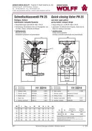
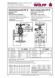
Remarks for Installation<br />
Use the Right Torque for the Bolts<br />
In order to allow maximum joint movements to prevent damages to the rubber sphere, the bolts must be inserted<br />
through the flange with the heads of the bolts on the joint side.<br />
To secure the joint to the pipe the bolts should be tightened crosswise, applying the following torque:<br />
for expansion joints up to a nominal diameter of 80 mm<br />
for expansion joints larger than a nominal diameter of 80 mm<br />
60 Nm (max.)<br />
80 Nm (max.)<br />
Use the Right Counter Flange<br />
For a proper, durable and safe connection the inner diameter of the counter flange should not be larger than the inner<br />
diameter of the rubber joint and the sealing surface should be even to ensure maximum sealing.<br />
Turbulence within the joint could cause noise, pressure loss or even leakage at the connection.<br />
RIGHT WRONG SOLUTION<br />
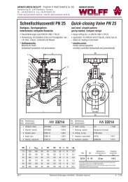
Pipe Anchors and Guides<br />
A main pipe anchor must be designed to withstand the forces and torques of the pipe section to which it is attached.<br />
In case of a pipe section containing one or more unrestrained expansion joints, these will have to absorb of the full<br />
line thrust due to pressure and flow, the forces and/or torques required to deflect the expansion joint (large diameters<br />
AW 1376), frictional forces due to pipe guides, etc. An intermediate pipe anchor must be designed to withstand only<br />
the forces and/or torques required to deflect the expansion joint, frictional forces due to pipe guides, etc.<br />
Correct alignment of the pipe is of vital importance in the proper function of the expansion joint.<br />
Install the joint close to an anchor and place a pipe guide behind the joint at the distance of about 1,5 x pipe<br />
diameter.<br />
pipe guides<br />
main anchor<br />
intermediate anchor<br />
main anchor
ARMATUREN-WOLFF • Friedrich H. Wolff GmbH & Co. KG<br />
Oehleckerring 29 • 22419 Hamburg - Germany<br />
Tel. +49 (40) 532 87 30 • Fax +49 (40) 532 87 329<br />
Email: aw@armaturen-wolff.de • Internet: www.armaturen-wolff.de<br />
ARMATUREN<br />
Tie Rods, Limit Rods and Hinge construction<br />
shall be constructed that they are able to absorb all appearing dynamic and static forces at a failure of a supporting point of a<br />
pipe.<br />
Limit rods to restrict the bellows axial<br />
movement range during normal operation. In<br />
the event of a main anchor failure, they are<br />
designed to prevent bellows overextension<br />
while restraining the full pressure loading<br />
and dynamic forces generated by the anchor<br />
failure.<br />
Lugs are welded to the flanges.<br />
Tie rods with external spherical bearings,<br />
whose primary function is to continuously<br />
restrain the full bellows pressure thrust during<br />
normal operation while permitting only lateral<br />
deflection.<br />
The lugs are integrated in the overall flanges.<br />
Tie rods with external and internal spherical<br />
bearing, whose primary function is to<br />
continuously restrain the full bellows pressure<br />
thrust during normal operation while permitting<br />
only lateral deflection.<br />
The lugs are welded into the flanges.<br />
Spool type expansion joint with limit rods to<br />
restrict the bellows axial movement range<br />
during normal operation. In the event of a main<br />
anchor failure, they are designed to prevent<br />
bellows overextension or over-compression<br />
while restraining the full pressure loading<br />
and dynamic forces generated by the anchor<br />
failure.<br />
The loose lugs are bolted to the steel flanges.<br />
Angular expansion joint with hinge plates<br />
attached to the flanges permitting angular<br />
rotation in one plane. The hinges and hinge<br />
pins must be designed to restrain the thrust<br />
forces due to internal pressure and extraneous<br />
forces, where applicable.<br />
Hinged expansion joints should be used in<br />
sets of two or three to function properly.