µLinc Processor
TLAser203 Manual - LaserLinc, Inc.
TLAser203 Manual - LaserLinc, Inc.
- No tags were found...

You also want an ePaper? Increase the reach of your titles
YUMPU automatically turns print PDFs into web optimized ePapers that Google loves.
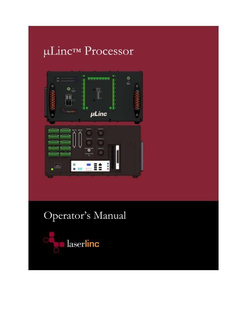
<strong>µLinc</strong> <strong>Processor</strong><br />
Operator’s Manual
Copyright © LaserLinc, Inc. 1999–2012<br />
All rights reserved<br />
Copyright<br />
LaserLinc, Inc. copyrights this manual with all rights reserved. Under the copyright laws, this manual<br />
may not be reproduced in any form, in whole or part, without prior written consent of LaserLinc,<br />
Inc.<br />
Disclaimer<br />
LaserLinc, Inc. has reviewed this manual thoroughly in order to ensure that it will be a useful guide<br />
to your <strong>µLinc</strong> <strong>Processor</strong>. All statements, technical information, and recommendations in this manual<br />
and in any guides or related documents are believed reliable, but the accuracy and completeness<br />
thereof are not guaranteed or warranted, and they are not intended to be, nor should they be<br />
understood to be, representations or warranties concerning the product described.<br />
Your laser scan micrometer and other hardware and software included with your system have been<br />
sold to you subject to the limited warranties set forth in the warranty section set forth in your quote<br />
you were issued before purchase and license agreement enclosed with the software CD. Further,<br />
LaserLinc, Inc. reserves the right to make changes in the specifications of the products described in<br />
this manual at any time without notice and without obligation to notify any person of such change.<br />
If you have questions regarding your laser scan micrometer system or the information in this<br />
manual, please call LaserLinc, Inc. customer service department at 1-888-707-4852.<br />
Trademarks<br />
LaserLinc, <strong>µLinc</strong>, TLAser122, TLAser222, TLAser122s, Triton312, Triton 330, TLAser400 and<br />
Total Vu are registered trademarks. The LaserLinc logo is a trademark of LaserLinc, Inc.<br />
Other brands and product names mentioned in this manual may be trademarks or registered<br />
trademarks of their respective companies.<br />
LaserLinc, Inc.<br />
777 Zapata Dr ▪ Fairborn OH 45324<br />
Phone: 937-318-2440 ▪ Fax: 937-318-2445<br />
info@laserlinc.com ▪ www.laserlinc.com
Read Me First: Safety and Electromagnetic Compatibility<br />
This chapter contains safety instructions and electromagnetic compatibility (EMC) information for<br />
the hardware it accompanies. This chapter is a supplement to the hardware documentation. Read<br />
this chapter before installing and using the <strong>µLinc</strong>.<br />
Safety Information<br />
This section contains important safety information that you must follow when installing and using<br />
the hardware.<br />
Do not operate the hardware in a manner not specified in this document and in the user<br />
documentation. Misuse of the hardware can result in a hazard. You can compromise the safety<br />
protection if the hardware is damaged in any way. If the hardware is damaged, return it to<br />
LaserLinc for repair.<br />
Do not substitute parts or modify the hardware except as described in this document. Use the<br />
<strong>µLinc</strong> only with the accessories and cables specified in the installation instructions or specifications.<br />
You must have all covers installed during operation of the <strong>µLinc</strong>.<br />
Do not operate the <strong>µLinc</strong> in an explosive atmosphere or where there may be flammable gases or<br />
fumes.<br />
iii
Contents<br />
Read Me First: Safety and Electromagnetic Compatibility.........................................................................iii<br />
Safety Information .......................................................................................................................................iii<br />
<strong>µLinc</strong>–Theory of Operation.............................................................................................................................1<br />
Intended Use of the Equipment .................................................................................................................1<br />
Safety Considerations ........................................................................................................................................2<br />
Instalation and Operation.................................................................................................................................3<br />
Safety Information ........................................................................................................................................3<br />
Connecting Safety Ground ..........................................................................................................................4<br />
Connecting to Power Source.......................................................................................................................4<br />
Mounting /Installation .................................................................................................................................4<br />
Mounting Hole Drawing..........................................................................................................................5<br />
<strong>µLinc</strong> Front And Back Panels .....................................................................................................................6<br />
Connections and Cabling .............................................................................................................................7<br />
<strong>µLinc</strong> Back Panel – Digital I/O Map.........................................................................................................8<br />
<strong>µLinc</strong> Back Panel – Control I/O Map.......................................................................................................9<br />
Appendix 1 Preventive Maintenance And Troubleshooting.....................................................................10<br />
Cleaning ........................................................................................................................................................10<br />
Exterior Cleaning....................................................................................................................................10<br />
Fan Filter Cleaning – Monthly or as needed.......................................................................................10<br />
Troubleshooting ..........................................................................................................................................11<br />
Problem: Won’t power-on or no video ...............................................................................................11<br />
Electrical Specifications..............................................................................................................................11<br />
Environment Specifications.......................................................................................................................12<br />
Connectivity Specifications........................................................................................................................12<br />
Specifications—Software / Total Vu.......................................................................................................13<br />
iv
<strong>µLinc</strong>–Theory of Operation<br />
LaserLinc designed the <strong>µLinc</strong> processor specifically for integration with laser and ultrasonic<br />
measurement systems. Connectors for all system I/O are located on the back of the unit (this<br />
includes connectors for scanning laser micrometers, alarms, control, encoder input, and an<br />
UltraGauge+ wall thickness system).<br />
Additionally, the <strong>µLinc</strong> includes detachable screw terminals for digital I/O, control, and analog I/O.<br />
The unit uses standard computer components and runs LaserLinc’s Total Vu software.<br />
Other options include dual-video output, dual-LAN ports (with UltraGauge+ installations), internal<br />
24 VDC power, and redundant, fault-tolerant storage. The <strong>µLinc</strong> has a variety of mounting kits:<br />
rack, DIN-rail, handles, and rubber feet.<br />
The <strong>µLinc</strong> can also be configured to work with laser micrometers from other manufacturers, using<br />
the TLAser400 micrometer interface card. With the TLAser400 card, you can eliminate<br />
processors that are costly to buy and repair, allowing you to minimize capital investment while<br />
bringing the latest measurement/data processing and control technology to the plant floor.<br />
Intended Use of the Equipment<br />
<strong>µLinc</strong> <strong>Processor</strong> is intended for use in data acquisition, processing, and storage, in conjunction with<br />
measuring devices such as laser scan micrometers and ultrasonic measurement devices for industries<br />
including (but not limited to) wire, cable, fiber, hose, tube, pipe, and centerless grinding.<br />
1
Safety Considerations<br />
When the <strong>µLinc</strong> <strong>Processor</strong> is used in conjunction with laser micrometers, be sure to avoid direct<br />
exposure of human eyes to laser beams emitted from laser diodes. Even though barely visible<br />
and/or invisible to the human eye, they can be quite harmful. In particular, avoid looking directly<br />
into a laser diode or collimated beam along its optical axis when the diode is activated.<br />
LaserLinc, Inc. certifies compliance with U.S. safety regulations (21 CFR Chapter I, Subchapter J) on<br />
laser products, as stipulated by the U.S. Department of Health and Human Services. LaserLinc, Inc.<br />
laser measurement products correspond to the category CLASS II LASER PRODUCT in the<br />
regulation.<br />
– This icon denotes a caution, which advises you of precautions to take to avoid injury, data<br />
loss, or a system crash. When this symbol is marked on the product, refer to the Read Me First:<br />
Safety and Electromagnetic Compatibility chapter for precautions to take.<br />
2
Instalation and Operation<br />
This chapter describes how to install and operate the <strong>µLinc</strong>. Before connecting the <strong>µLinc</strong> to a power<br />
source, read this chapter and the Read Me First: Safety and Electromagnetic Compatibility chapter.<br />
Your <strong>µLinc</strong> will be pre-configured to include all purchased options, laser micrometers and Ultra<br />
Gauge+ hardware. Once all hardware is connected, Total Vu is ready to run.<br />
Safety Information<br />
– Caution Before undertaking any maintenance carefully read the following caution notices.<br />
This equipment contains voltage hazardous to human life and safety, and is capable of inflicting<br />
personal injury.<br />
• <strong>µLinc</strong> Grounding—The <strong>µLinc</strong> requires a connection from the premise wire safety ground to<br />
the chassis ground. The earth safety ground must be connected during use of this equipment<br />
to minimize shock hazards. Refer to the Connecting Safety Ground section for instructions<br />
on connecting safety ground.<br />
• Live Circuits—Operating personnel must not remove protective covers when operating the<br />
<strong>µLinc</strong>. Adjustments and service to internal components must be undertaken only by Laser-<br />
Linc personnel.<br />
• Explosive Atmosphere—Do not operate the scanner in conditions where flammable gases<br />
are present. Under such conditions, this equipment is unsafe and may ignite the gases or gas<br />
fumes.<br />
• Part Replacement—Only service this equipment with parts that are exact replacements, both<br />
electrically and mechanically. Contact LaserLinc for replacement part information. Installation<br />
of parts with those that are not direct replacements may cause harm to personnel operating<br />
the scanner. Furthermore, damage or fire may occur if replacement parts are unsuitable.<br />
3
4 INSTALLATION AND O PERATION<br />
• Modification—Do not modify any part of the <strong>µLinc</strong> from its original condition. Unsuitable<br />
modifications may result in safety hazards.<br />
Connecting Safety Ground<br />
– Caution: The <strong>µLinc</strong> is designed with a 3-position inlet that connects the processor ground<br />
line to the chassis ground. To minimize shock hazard, make sure the electrical power outlet you use<br />
to power the processor has an appropriate earth safety ground.<br />
Connecting to Power Source<br />
– Caution: To deactivate power completely, you must disconnect the data and power port<br />
cable.<br />
Attach input power through the power port inlet using the cable supplied.<br />
Mounting /Installation<br />
The <strong>µLinc</strong> may be table-mounted (default), rack-mounted or rail-mounted. Please contact LaserLinc<br />
for custom installations. Orientation—any orientation is acceptable, as long as the mounting is<br />
secure and free from vibration and away from liquids.<br />
http://www.laserlinc.com/Mounting_drawings/LaserLinc-microLinc_mount.pdf
INSTALLATION AND OPERATION 5<br />
Mounting Hole Drawing<br />
Figure 1 <strong>µLinc</strong> mounting diagram.
6 INSTALLATION AND O PERATION<br />
<strong>µLinc</strong> Front And Back Panels
INSTALLATION AND OPERATION 7<br />
Figure 2 <strong>µLinc</strong> front (top) and back (bottom).<br />
Connections and Cabling<br />
Your <strong>µLinc</strong> comes with an IEC molded power cord of approximately 6' (2 meters). The wall plug<br />
will have the connector appropriate to your locale. The AC mains supply cords used with the <strong>µLinc</strong><br />
must meet the requirements of ANSI/UL817 for use in the United States, CSA C22.2 21 and 49 for<br />
use in Canada, and IEC 60799 for use in the European Union. AC mains power supply cords used<br />
with the <strong>µLinc</strong> in other countries must be approved by the authority having jurisdiction in that<br />
country. Any power cord used must be no longer than 3 meters.<br />
Your <strong>µLinc</strong> will be factory configured for the proper AC mains voltage.<br />
1 Connect AC power cord to AC power inlet on rear of <strong>µLinc</strong>.<br />
2 Connect scanner to appropriate back panel scanner interface, typically Scanner 1, Scanner 2, etc.<br />
2.1 For specific scanner type and target connector information, consult your <strong>µLinc</strong> Quick Start<br />
Guide.<br />
3 Connect the video monitor (optional) to either the VGA or DVI monitor input ports.<br />
The processor will self-configure to the selected output.<br />
4 Connect provided keyboard mouse.<br />
5 Connect alarms and/or control.<br />
These connections may be defined later. Refer to I/O maps in Figure 3.<br />
6 Press main power button on front panel.<br />
The green ring should illuminate.<br />
7 Press processor power button on front panel.<br />
The green ring should illuminate and the monitor should display the boot-up process into<br />
Windows.<br />
8 After Windows finishes the boot-up process, start Total Vu by double-clicking the Total Vu<br />
icon on the desktop.<br />
Total Vu should start up.
8 INSTALLATION AND O PERATION<br />
<strong>µLinc</strong> Back Panel – Digital I/O Map<br />
Figure 3 example: Normally Open (NO) contact closure 1D
INSTALLATION AND OPERATION 9<br />
<strong>µLinc</strong> Back Panel – Control I/O Map<br />
INTERFACE<br />
RELAYS CTR05/4302 CTR10/4304<br />
Loop 1 1A/1B — PW<br />
Loop 2 2A/2B — PW<br />
Loop 3 3A/3B — PW<br />
Loop 4 4A/4B — PW<br />
Loop 5 5A/5B — PW<br />
Counter 2A/3A PW PW<br />
Counter 4A/5A PW PW<br />
Counter 2B/3B — PW<br />
Counter 4B/5B — PW<br />
Counter 3A/5A PC PC<br />
Counter 3B/5B — PC<br />
PW: Pulse Width Interface<br />
PC: Pulse Count Interface<br />
Table 1 example: (Jog-Up) using Relay 2A. Define function in ACTIONS in Total Vu software. Use relay 2A (Jog-Up) in<br />
conjunction with relay 3A for Jog-Down function.<br />
Figure 4 <strong>µLinc</strong> connectors.
Appendix 1 Preventive Maintenance And Troubleshooting<br />
This chapter describes basic maintenance procedures you can perform on the <strong>µLinc</strong> <strong>Processor</strong>.<br />
Read the Read Me First: Safety and Electromagnetic Compatibility section before attempting any of the<br />
procedures in this chapter.<br />
Cleaning<br />
Exterior Cleaning<br />
Clean dust and dirt from the <strong>µLinc</strong> exterior as needed, based on the operating environment. Periodic<br />
cleaning increases reliability and cooling performance.<br />
– Caution: Do not wash the connectors. Cover these components while cleaning the scanner.<br />
Do not use harsh chemical cleaning agents; they may damage the <strong>µLinc</strong>’s finish. Avoid chemicals<br />
that contain benzene, toluene, xylene, acetone, or similar solvents.<br />
Clean the exterior surfaces of the scanner with a dry lint-free cloth or a soft-bristle brush. If any dirt<br />
remains, wipe with a cloth moistened in a mild soap solution or a cleaning agent such as Fantastic or<br />
Krud Kutter. Remove any soap residue by wiping with a cloth moistened with clear water. Do not<br />
use abrasive compounds on any part of the scanner.<br />
Fan Filter Cleaning – Monthly or as needed<br />
The fans filters of the <strong>µLinc</strong> must always be clean to ensure the proper cooling. Depending on your<br />
environment, your filters may require more or less frequency of cleaning. Visually inspect for<br />
blockage.<br />
1. To clean the fan filters:<br />
1.1. Power down <strong>µLinc</strong>.<br />
10
APPENDIX 1: PREVENTIVE M AINTENANCE AND TROUBLESHOOTING 11<br />
1.2 Remove AC power cord.<br />
1.3 Gently remove fan cover using small flat-blade screw driver.<br />
1.4 Remove foam filter material and wash in hot soapy water.<br />
1.5 Dry, and re-install.<br />
Note: There are NO user-serviceable parts inside the <strong>µLinc</strong>—removing the cover will<br />
VOID your warranty.<br />
Troubleshooting<br />
Problem: Won’t power-on or no video<br />
Possible Causes:<br />
AC power cord not connected.<br />
Mains button not engaged—push to illuminate.<br />
<strong>Processor</strong> button not engaged—push to illuminate.<br />
Video cable not connected or loose—ensure connectivity at both ends.<br />
Monitor not working—power-on monitor.<br />
Please contact LaserLinc for further help.<br />
Electrical Specifications<br />
Operating voltage range 115 VAC model 1<br />
Operating voltage range 230 VAC model 1<br />
Input frequency<br />
Operating frequency range 1<br />
Input current rating 115 VAC Model<br />
Input current rating 230 VAC Model<br />
Over current protection<br />
Power disconnect<br />
104–132 VAC<br />
207–264 VAC<br />
50/60 Hz<br />
47–63 Hz<br />
400W<br />
200W<br />
Internally Fused. Not user serviceable<br />
The AC power cable provides main power disconnect.<br />
1The operating range is guaranteed by design.
12 APPENDIX 1: PREVENTIVE M AINTENANCE AND T ROUBLESHOOTING<br />
Environment Specifications<br />
Dimensions (H x W x D<br />
(221mm x 406mm x 320mm) 8.7˝ x 16˝ x 12.6˝<br />
Approx. Weight<br />
30lbs (13.6kg)<br />
Environmental<br />
Operating Temperature 41F º to 104 F º (5 º C – 40 º C)<br />
Operating relative humidity<br />
Maximum 80% relative humidity for temperatures up to<br />
31º C, decreasing linearly to 50% at 40º C<br />
Installation category<br />
II<br />
Pollution degree 2<br />
Protection Class<br />
Class 1 grounded<br />
Operating location<br />
Indoor use only<br />
Maximum Altitude<br />
2000 m (at 25º C ambient)<br />
Connectivity Specifications<br />
Maximum Scanners (LaserLinc) (12) :122/130/160/1120/2120/230/260/331/<br />
(6) 222/203<br />
(3) 312/330<br />
Maximum Scanners (Others) (12) Beta LaserMike / Accuscan / Zumbach / Keyence /<br />
Aereol / Takikawa / Mitutoyo<br />
Encoders / ZL DIN 1/1<br />
LAN 10/100/1000 2<br />
Internal 12/24 VDC<br />
Yes—optional<br />
I/O Connections<br />
Detachable screw terminals<br />
Digital I/O<br />
8 Inputs / 8 Outputs<br />
Additional available—contact LaserLinc<br />
Control Loops<br />
Up to 10 Pulse Width / 5 Pulse count<br />
Analog I/O<br />
16 inputs / 8 Outputs—up to 16 bits resolution<br />
UltraGauge+<br />
(2) DSP unit / 16 channels
APPENDIX 1: PREVENTIVE M AINTENANCE AND TROUBLESHOOTING 13<br />
Specifications—Software / Total Vu<br />
Operating System<br />
Windows 7 / 32-bit / 64-bit<br />
Applications<br />
Total Vu software<br />
Hard Disk<br />
160MB<br />
Memory<br />
Up to 8 GB<br />
Video VGA/DVI/HDMI (2x) 1600 x 1024<br />
USB<br />
2.0 compliant<br />
Audio<br />
standard