Lenze BA14.0169 Spring Operated Brake BFK ... - Southern Power
Lenze BA14.0169 Spring Operated Brake BFK ... - Southern Power
Lenze BA14.0169 Spring Operated Brake BFK ... - Southern Power
- No tags were found...

Create successful ePaper yourself
Turn your PDF publications into a flip-book with our unique Google optimized e-Paper software.
BA 14.0169<br />
409 407 GB<br />
Operating Instructions<br />
KL454-008-A<br />
S<br />
Electromagnetically<br />
released twin-circuit<br />
spring-operated brake<br />
Type <strong>BFK</strong>454- PP
Product Key<br />
B FK 454 - PP<br />
Product group: <strong>Brake</strong>s<br />
Product type: <strong>Spring</strong>-<strong>Operated</strong> <strong>Brake</strong><br />
Type<br />
Dimensions<br />
l<br />
The information given in the product key, on the nameplate and on packaging labelling applies<br />
to spring-operated brakes of the <strong>BFK</strong>454 series.<br />
These Operating Instructions are valid for the following spring-operated brake models/types:<br />
<strong>BFK</strong>454-10<br />
<strong>BFK</strong>454-12<br />
<strong>BFK</strong>454-14<br />
<strong>BFK</strong>454-16<br />
<strong>BFK</strong>454-18<br />
<strong>BFK</strong>454-20<br />
<strong>BFK</strong>454-25<br />
BA 14.0169<br />
Author: <strong>Lenze</strong> GmbH & Co KG, <strong>Brake</strong>s<br />
3 th edition: 07/00<br />
2 BA <strong>BFK</strong>454 GB 3.0
Nameplate<br />
Layout<br />
Field 1<br />
Field 2<br />
Field 3<br />
Layout for sizes 10 -16 and 18 - 25<br />
Field Contents Example: size 10-16<br />
1 Manufacturer <strong>Brake</strong> type Type no.<br />
2 Rated voltage Rated power Rated braking torque CE labelling<br />
3 Date of manufacture<br />
-D <strong>BFK</strong>454-10 Nr.401473<br />
205V DC 33W<br />
15NM<br />
80715<br />
Field Contents Example: size 18-25<br />
1 Manufacturer<br />
2 <strong>Brake</strong> type<br />
3 Rated voltage Rated power<br />
Type: <strong>BFK</strong>454-25<br />
205V DC 110W<br />
D - AERZEN<br />
4 Rated braking torque Date of manufacture 400NM 80715<br />
5 Type no. CE labelling Nr. 521388<br />
Packaging sticker<br />
Layout<br />
Field 1<br />
Field 2<br />
Field 3<br />
Field 4<br />
Field 5<br />
Assembly<br />
Field Contents Example<br />
1 Manufacturer Barcode no.<br />
2 Name Type no.<br />
3 Type: see product key Rated braking torque Qty. per carton<br />
4 Rated voltage and power Packaging date<br />
D-AERZEN<br />
MAGNETTEIL KPL. Nr. 401473<br />
Type: y <strong>BFK</strong>454-10 15Nm 1 Stück<br />
205V DC 33W 80715<br />
5 Supplement CE labelling Rostschutzverpackung-Reibflächen fettfrei halten!<br />
BA <strong>BFK</strong>454 GB 3.0<br />
3
Contents<br />
1 Preface and General Information ...........................................<br />
6<br />
1.1 How to use these Operating Instructions ................................................<br />
6<br />
1.1.1 Terminology used .........................................................<br />
6<br />
1.2 Scope of Delivery .................................................................<br />
6<br />
1.3 <strong>Lenze</strong> drive systems ...............................................................<br />
7<br />
1.3.1 Labelling ................................................................<br />
7<br />
1.3.2 Application as directed .....................................................<br />
7<br />
1.3.3 Legal rules ..............................................................<br />
7<br />
2 Safety Information ......................................................<br />
8<br />
2.1 Persons responsible for safety .......................................................<br />
8<br />
2.2 General Safety Information ..........................................................<br />
8<br />
2.3 Testing and expertise evaluation ......................................................<br />
9<br />
2.4 Layout of the Safety Information ......................................................<br />
10<br />
3 Technical Data ......................................................... 11<br />
3.1 Product description ...............................................................<br />
11<br />
3.1.1 General .................................................................<br />
11<br />
3.1.2 <strong>Brake</strong>s .................................................................<br />
12<br />
3.1.3 <strong>Brake</strong> release ............................................................<br />
13<br />
3.1.4 Hand release .............................................................<br />
13<br />
3.1.5 Wear display / monitoring option ..............................................<br />
13<br />
3.1.6 Decrease braking torque ....................................................<br />
13<br />
3.2 Rated data ......................................................................<br />
14<br />
3.3 Switching times ..................................................................<br />
15<br />
3.4 Switching frequency / switching ......................................................<br />
16<br />
3.5 Emissions ......................................................................<br />
17<br />
4 Installation ............................................................ 18<br />
4.1 Required tools ...................................................................<br />
18<br />
4.2 Assembly .......................................................................<br />
19<br />
4.2.1 Preparation ..............................................................<br />
19<br />
4.3 Installation procedure ..............................................................<br />
19<br />
4.3.1 Mounting the hub on the shaft ................................................<br />
19<br />
4.3.2 Mounting the brake ........................................................<br />
19<br />
4.3.3 Assembly of the friction plate, size 10 to 16 ......................................<br />
21<br />
4.3.4 Mounting the flange ........................................................<br />
22<br />
4.3.5 Mounting the seal ring ......................................................<br />
23<br />
4.4 Electrical connection ..............................................................<br />
24<br />
4 BA <strong>BFK</strong>454 GB 3.0
Contents<br />
5 Commissioning and operation ............................................. 25<br />
5.1 Function test ....................................................................<br />
25<br />
5.1.1 Release / voltage check .....................................................<br />
25<br />
5.1.2 Microswitch - wear check ...................................................<br />
25<br />
5.1.3 Twin-circuit function .......................................................<br />
26<br />
5.1.4 Hand release .............................................................<br />
27<br />
5.2 Reducing brake torque .............................................................<br />
28<br />
5.3 During operation .................................................................<br />
28<br />
6 Maintenance / repair .................................................... 29<br />
6.1 Inspection intervals ...............................................................<br />
29<br />
6.2 Inspections .....................................................................<br />
29<br />
6.2.1 Rotor thickness ...........................................................<br />
29<br />
6.2.2 Air gap .................................................................<br />
29<br />
6.2.3 Release / voltage .........................................................<br />
30<br />
6.2.4 Twin-circuit function .......................................................<br />
30<br />
6.3 Maintenance ....................................................................<br />
30<br />
6.3.1 Adjusting the air gap .......................................................<br />
30<br />
6.3.2 Replacing the rotor ........................................................<br />
31<br />
6.3.3 Replacing the entire stator ...................................................<br />
31<br />
6.4 Spare parts lists ..................................................................<br />
31<br />
6.4.1 Spare parts list for size 10 to 16 ..............................................<br />
32<br />
6.4.2 Spare parts list for size 18 to 25 ..............................................<br />
33<br />
6.4 Spare parts order .................................................................<br />
34<br />
7 Troubleshooting ........................................................ 36<br />
Declaration of Conformity / Manufacturer’s Certification<br />
Service addresses<br />
BA <strong>BFK</strong>454 GB 3.0<br />
5
Preface and general information<br />
1 Preface and General Information<br />
1.1 How to use these Operating Instructions<br />
l<br />
l<br />
l<br />
These Operating Instructions are intended to ensure safe operation on and with the<br />
spring-operated brake with electromagnetic release. They include safety instructions that<br />
must be adhered to.<br />
All persons working on and/or with the spring-operated brake with electromagnetic release<br />
must have these Operating Instructions available to them at all times when so doing and must<br />
adhere to the information and notes relevant to their activities.<br />
The Operating Instructions must always be complete and wholly legible.<br />
1.1.1 Terminology used<br />
<strong>Brake</strong><br />
The term ”spring-operated brake” is used to mean ” spring-operated brake with electromagnetic<br />
release” throughout the text that follows.<br />
Drive system<br />
The term ”drive system” is used throughout the text that follows to mean drive systems with<br />
spring-operated brake with electromagnetic release.<br />
1.2 Scope of Delivery<br />
l<br />
l<br />
The drive systems are individually assembled on the modular principle. Scope of delivery is<br />
stated in the accompanying paperwork.<br />
Check immediately on receipt whether the goods delivered comply entirely with the<br />
accompanying documentation. <strong>Lenze</strong> canot accept liability for any defects notified at a later<br />
date. Please immediately submit a claim for<br />
– visible transport damage to the forwarder;<br />
– and to the <strong>Lenze</strong> subsidiary/agency responsible in case of incomplete delivery or visible<br />
defects.<br />
6 BA <strong>BFK</strong>454 GB 3.0
Preface and general information<br />
1.3 <strong>Lenze</strong> drive systems<br />
1.3.1 Labelling<br />
l <strong>Lenze</strong> drive systems and components are uniquely designated by the content of their<br />
nameplate/s.<br />
l Manufacturer: Location:<br />
<strong>Lenze</strong> GmbH & Co KG Bremsen Wülmser Weg 5<br />
POB 10 13 52<br />
D-31855 Aerzen<br />
D-31763 Hameln<br />
1.3.2 Application as directed<br />
l<br />
<strong>Lenze</strong> drive systems<br />
– are intended for use in machinery and plant;<br />
– may only be used for their designed purpose/s as ordered;<br />
– may only be operated under the conditions given in the Operating Instrructions, and<br />
– may not be operated outside their applicable perfomance/capacity limits.<br />
Any and all other use/s is/are improper.<br />
1.3.3 Legal rules<br />
Liability<br />
l<br />
l<br />
The information, data and notes in these Operating Instructions were current at the time of<br />
printing. No right to make claim/s concerning drive systems already supplied can be made on<br />
the basis of the details, illustrations and descriptions contained herein.<br />
We accept no liability for damage or operational malfunction due to:<br />
–improperuse;<br />
– unauthorised modification/s to drive system/s;<br />
– improper operation of/with the drive system/s;<br />
– control/operation errors, or<br />
– disregarding these Operating Instructions.<br />
Warranty<br />
l<br />
l<br />
l<br />
Please refer to <strong>Lenze</strong> GmbH & Co. KG’s Terms and Conditions of Sale for our warranty<br />
conditions.& Co KG.<br />
Warranty claims must be advised <strong>Lenze</strong> immediately on the defect/fault/malfunction<br />
concerned being detected to be effective.<br />
The warranty is null and void should any claim/s of liability not be effective in law.<br />
BA <strong>BFK</strong>454 GB 3.0<br />
7
Safety information<br />
2 Safety Information<br />
2.1 Persons responsible for safety<br />
Operator<br />
l<br />
l<br />
An operator is any legal or natural person using the spring-operated brake or on whose behalf<br />
same is used.<br />
The operator or his designated safety officer must ensure<br />
– that all relevant rules, notes and laws are adhered to;<br />
– that only properly qualified personnel work on or with the spring-operated brake;<br />
– that such personnel have the Operating Instructions available to them during all relevant<br />
work/s, and<br />
– that personnel not properly qualified are prohibited from working on and/or with the<br />
spring-operated brake.<br />
Properly qualified staff<br />
Properly qualified staff are persons authorised by those responsible for plant safety to carry out such<br />
activities as may be required and who are able to recognise and avoid all potential risks. Such<br />
persons are so authorised on the basis of their training, experience and equipment familiarisation<br />
and their knowledge of applicable standards, rules, accident prevention regulation and operating<br />
conditions. (Definition of specialist personnel according to IEC 364)<br />
(Definition of specialist personnel according to IEC 364)<br />
2.2 General Safety Information<br />
l<br />
l<br />
l<br />
l<br />
l<br />
l<br />
l<br />
l<br />
No claim is made for this safety information being comprehensive. In the event of queries<br />
and/or problems, please refer to your <strong>Lenze</strong> agent/representative.<br />
The spring-operated brake is state-of-the-art when supplied and is considered fundamentally<br />
safe to operate.<br />
Risks to persons, the spring-operated brake itself and/or to the operator’s assets may arise in<br />
operating the brake if<br />
– personnel who are not properly qualified work on/with the brake, and/or<br />
– the spring-operated brake is improperly used.<br />
The spring-operated brakes must be so designed that, if if correctly installed and ifused for<br />
their designed purpose in fault-free operation, their function is fulfilled and no risk to persons<br />
arises. This also applies to their interaction with the entire plant..<br />
Only use the spring-operated brake when it is in a fault-free condition.<br />
Retrofitting, modification and/or any change/s to the spring-operated brake/s are prohibited<br />
as a matter of principle. Prior reference to <strong>Lenze</strong> is essential in ALL cases.<br />
Friction linigs and/or surfaces must never come into contact with oil or grease; even minor<br />
quanitites of either/both greatly reduce braking torque.<br />
Given operating conditions compliant with Protection Type IP54, no changes in braking<br />
torque need normally be anticipated. However, proper functioning of the mechanical<br />
components needs to be tested under the particular operating conditions applicable as such<br />
conditions can vary so greatly.<br />
8 BA <strong>BFK</strong>454 GB 3.0
Safety information<br />
<strong>Spring</strong>-operated <strong>BFK</strong>454 brake operating range and limitationsPP:<br />
l<br />
l<br />
l<br />
l<br />
l<br />
l<br />
l<br />
l<br />
Not to be used in explosion-endangered or corrosive atmospheres.<br />
There are no humidity limitations.<br />
Ambient temperaturesfrom -20EC to+40EC are permissible.<br />
Where humidity is high and temperature low,<br />
measures must be taken to ensure the armature plate and rotor do not freeze solid.<br />
Electrical connections must be protected against short-circuits/contact.<br />
The flow of cooling air must not be impeded in any way whatsoever.<br />
In reverse operation, we recommend the hub be additionally affixed to the shaft with<br />
adhesive..<br />
2.3 Testing and expertise evaluation<br />
l<br />
l<br />
In an expertise dated 29.06.1998 BT BY-FAS/re-id, adherence to the requirements of the TRA<br />
200 (TRA 227, 228.1 (1), 228.2), DIN EN 81 Part 1 [section 12.4.2.1 (para. 2), 12.4.2.4,<br />
12.4.2.5, 12.4.2.6] and pr EN 81 - 1, issue of March 1997 [section 12.4.2.1 (section 2. ),<br />
12.4.2.4, 12.4.2.5] was confirmed by the TÜV Süddeutschland ( = German Technical<br />
Monitoring Association, South Germany).<br />
The brakes must be supplied complete with testing instructions..<br />
BA <strong>BFK</strong>454 GB 3.0<br />
9
Safety information<br />
2.4 Layout of the Safety Information<br />
l<br />
All Safety Information in these Operating Instructions is laid out uniformly as below.<br />
Signal word!<br />
Informational text<br />
– The pictograph identifies the type of risk.<br />
– The signal word identifies the risk degree of severity.<br />
– The informational text describes the risk and advises on how it might be avoided.<br />
Warningofdangertopersons<br />
Icons used<br />
Warning of dangerous<br />
electric current<br />
Warning of a gerneral<br />
danger<br />
Signal words<br />
Danger!<br />
Warning!<br />
Caution!<br />
Warns of immediately impending danger.<br />
Consequnces nces if disregarded:<br />
death or very severe injury.<br />
Warns of a potentially very dangerous situation.<br />
Possible consequences iof disregarded:<br />
death or serious s injury.<br />
Warning of a potentially hazardous situation.<br />
Possibleconsequnces nces if disregarded:<br />
light or minor injury.<br />
Warning of danger to material/s<br />
Icons used<br />
Signal words<br />
Stop!<br />
Warns of potential danger to material/s.<br />
Possible consequences if disregarded:<br />
damage to the drive system/device or its environment.<br />
Icons used<br />
Other information<br />
Signal words<br />
Tip!<br />
Denotes a general useful tip.<br />
Following it eases handling/operating/controlling the drive system/device.<br />
10 BA <strong>BFK</strong>454 GB 3.0
Technical data<br />
3 Technical Data<br />
3.1 Product description<br />
3.1.1 General<br />
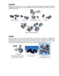
The twin-circuit spring-operated brake<br />
The twin-circuit system of the <strong>BFK</strong>454 brakes is created by splitting the armature plate into<br />
- the front armature plate and<br />
- the rear armature plate.<br />
The twin-circuit spring-operated <strong>BFK</strong>454-PP brake is designed to convert mechanical force and<br />
kinetic energy into heat at operating speeds up to 400 min -1 . Loads can be maintained without<br />
differential speed due to the static initial breakaway torque. Emergency braking from a differential<br />
speed of 3000 min -1 is possible.<br />
The stator is designed to be of thermal class F. Limiting winding temperature is 155 •C.<br />
Rear armature plate<br />
Front armature plate<br />
FIG 1<br />
KL454-009<br />
BA <strong>BFK</strong>454 GB 3.0<br />
11
Technical data<br />
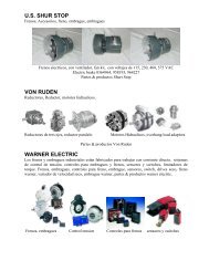
1 Stator<br />
2 Rotor<br />
3 Flange<br />
4 Lever<br />
5 Screws<br />
6 Pressure plate<br />
7 Hub<br />
8 Compression springs<br />
9 Sleeving screw<br />
10 Armature plate (front)<br />
11 Armature plate (rear)<br />
12 Hand release<br />
13 Adjustment<br />
Release direction<br />
KL454-003-A<br />
FIG 2<br />
Twin-circuit spring-operated brake type <strong>BFK</strong>454-PP<br />
Functional principle<br />
The braking torque is created by the pressure of several compression springs (8)via friction between<br />
the friction linings of the rotor (2), flange (3) and front armature plate (10). The brake is released<br />
electromagnetically.<br />
The front armature plate (10) is secured against torsion by two or more drill-holes in cylindrical rear<br />
armature plate (11) retainers. That part of braking torque created on the front armature plate (10) is<br />
born via the rear armature plate (11) by the sleeving screws (9). The compression force of the outer<br />
pole springs (8)affects the front armature plate via the rear armature plate (11), whereas the inner pole<br />
compression springs (8) directly affect the front armature plate (10).<br />
The thickness of the armature plates is so attuned to one another that the front plate (10) cannot be<br />
separated from the friction lining without the rear one (11). The rear plate (11) can on its part not fall<br />
from the stator (1) without its front mate (10).<br />
Armature plate separation hence does not occur in the friction surface area. Switching behaviour<br />
similar to that in one-piece armature plates is achieved. If the rear plate (11) clamps to the sleeving<br />
screw (9), then the front plate (10) can still fall from the stator (1) and at least 50% of braking torque<br />
is achieved.<br />
No relative axial motion between thearmature plates (10+11)when they fall from thestator (1)occurs<br />
in view of this design and in accordance with the above description. This means that the the front<br />
plate (10)cannot clamp on the sleeving screws (9)with simultaneous movement of the rear plate (11)<br />
as a matter of design principle.<br />
3.1.2 <strong>Brake</strong>s<br />
During braking, the rotor mounted axially movably on the toothed hub is pressed against the flange<br />
by the inner and outer compression springs via the front armature plate. The asbestos-free friction<br />
linings ensure a high braking torque with low wear. The braking torque is transmitted between flange,<br />
front armature plate and rotor by friction coupling. This torque is transmitted from rotor to shaft and<br />
from the front via the rear armature plate to the sleeving screws in the stator by positive engagement.<br />
12 BA <strong>BFK</strong>454 GB 3.0
Technical data<br />
3.1.3 <strong>Brake</strong> release<br />
When the brake is applied, there is an air gap between stator and armature plates of s Lü (FIG 2). To<br />
release the brake, the DC current provided is fed to the stator coil. The magnetic force generated<br />
attracts the armature plates toward the stator against the force of the springs. The rotor is then<br />
relieved of the spring compression force and can rotate freely.<br />
3.1.4 Hand release<br />
Manual release is designed for short-term release in dead condition (i.e. without current). This permits<br />
lowering the cabin to floor height even when the power fails. Manual release can be used to simulate<br />
loss of a braking circuit for brake testing purposes.<br />
3.1.5 Wear display / monitoring option<br />
The optionally available microswitch (changeover contact) monitors the air gap s Lü .Shortlybefore<br />
the max. permissible air gap s Lümax. is reached, the microswitch trips. Motor and brake operation is<br />
inhibited. In addition, a signal can be transmitted if desired.<br />
3.1.6 Decrease braking torque<br />
Please refer to chapter 5.2 for further information on this.<br />
Thetwin-circuit spring-operated type<strong>BFK</strong>454brakeis equipped withacentrally installed adjustment<br />
ring. This affects only the compression springs of the inner pole and hence the front armature plate<br />
(front brake circuit).<br />
The brake is supplied with the rated value of rated torque pre-set ex works. Undoing the adjustment<br />
ring permits the braking torque to be reduced by a max. 60% and hence optimally tailored to<br />
individual use. Compression spring force distribution between the two braking circuits is so selected<br />
that, after the adjustment ring (13)has been unscrewed, 50% of the braking torque is provided in each<br />
circuit. Twin-circuit brake operation is thus retained.<br />
Braking torque may only be reduced to the point at which the torque from the front circuit suffices<br />
alone to adhere to the required stopping distance.<br />
BA <strong>BFK</strong>454 GB 3.0<br />
13
14 BA <strong>BFK</strong>454 GB 3.0<br />
<br />
3.2 Rated data<br />
Type <strong>Power</strong> Voltage Coil<br />
resistance<br />
Rotor thickness<br />
Max.<br />
adjustment,<br />
permissible<br />
wear<br />
Max.<br />
projection of<br />
adjustment<br />
ring<br />
Pitch circle<br />
Screws for<br />
flange<br />
mounting<br />
(DIN6912)<br />
Minimum<br />
depth of<br />
clearing holes<br />
(installation<br />
flange)<br />
(W) (V) ) (mm) (mm) (mm) (mm) (mm) Thread 1) (mm) (kg)<br />
(W<br />
P 20 V R 3% Rated min. O max.<br />
<strong>BFK</strong>454-10 33 205<br />
20á<br />
1273 9 7 1.5 7.5 112 3xM6 3xM6 3 2.6<br />
<strong>BFK</strong>454-12 40 205 1051 10 8 2 9.5 132 3xM6 3xM6 4 4.3<br />
<strong>BFK</strong>454-14 53 205 793 10 7.5 2.5 11 145 3xM8 3xM8 3 6<br />
<strong>BFK</strong>454-16 56 205 751 11,5 8 3.5 10 170 3xM8 3xM8 6 9.2<br />
<strong>BFK</strong>454-18 85 205 494 13 10 3 15 196 6xM8 4xM8 2) 6 14<br />
<strong>BFK</strong>454-20 100 205 420 16 12 4 16.5 230 6xM10 4xM10 2) 7.5 21.9<br />
<strong>BFK</strong>454-25 110 205 382 20 15.5 4.5 18.5 278 6xM10 6xM10 9 32.5<br />
Type<br />
Braking torque<br />
Rated value at<br />
Max. speed<br />
n Omax<br />
Air gap<br />
s Lü<br />
Braking torque at<br />
n 0 (min -1 )<br />
Braking torque<br />
derating per<br />
Tightening torque<br />
n = 100min -1<br />
detent position<br />
M r (Nm) 20% (min -1 ) (mm) (%) (Nm) (Nm)<br />
Rated min. Normal Emergency Rated + 0,1 max.<br />
3)<br />
3) braking braking -0,05 4)<br />
1000 1500 3000 Screws Lever<br />
<strong>BFK</strong>454-10 15 (12/3) 6 (3/3) 400 3000 0.3 0.7 (0.45) 87 83 76 0.8 9.5 4.8<br />
<strong>BFK</strong>454-12 30 (24/6) 12 (6/6) 400 3000 0.3 0.8 (0.45) 85 81 74 1.3 9.5 4.8<br />
<strong>BFK</strong>454-14 60 (48/12) 24 (12/12) 400 3000 0.3 0.8 (0.45) 84 80 73 1.7 23 12<br />
<strong>BFK</strong>454-16 90 (72/18) 36 (18/18) 400 3000 0.3 0.8 (0.45) 83 79 72 1.6 23 12<br />
<strong>BFK</strong>454-18 150 (120/30) 60 (30/30) 400 3000 0.4 1.0 (0.6) 81 77 70 3.6 23 23<br />
<strong>BFK</strong>454-20 200 (160/40) 80 (40/40) 400 3000 0.4 1.3 (0.6) 79 75 68 5.6 46 23<br />
<strong>BFK</strong>454-25 400 (320/80) 160 (80/80) 400 3000 0.5 1.3 (0.75) 77 73 66 6.2 46 40<br />
D<br />
D<br />
1) Screw length depends on material/s and thickness of the client’s mounting surface.<br />
2) Thread in mounting surface 30 degrees inclined to centre axis of manual release lever<br />
3) ( ) Distribution of the prset brake torque to the front/back brake circuit (delivery).<br />
4) ( ) Max. permissible air gap for brake torques M Krated .<br />
D<br />
«<br />
Weight of<br />
complete<br />
stator<br />
Technical data
Technical data<br />
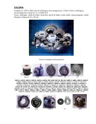
3.3 Switching times<br />
t 1 Engagement time<br />
t 2 Disengagement time( up to 0.1 M r )<br />
t 11 Response delay during engagement<br />
t 12 <strong>Brake</strong>torqueincreasetime<br />
K14.0583/1<br />
FIG 3<br />
Switching times diagram<br />
Type<br />
Braking torque at Qn=100<br />
min -1<br />
Max. switching per individual<br />
switching procedure<br />
Transition switching<br />
frequency<br />
Switching times (s)<br />
at s Lürated and M rrated<br />
M r (Nm) –20% (J) (h -1 ) Engage Disengage<br />
rated min. Q E S hü t 11 t 12 t 1 t 2<br />
<strong>BFK</strong>454-10 15 (12/3) 6 (3/3) 12000 40 0.02 0.02 0.04 0.08<br />
<strong>BFK</strong>454-12 30 (24/6) 12 (6/6) 24000 30 0.03 0.03 0.06 0.12<br />
<strong>BFK</strong>454-14 60 (48/12) 24 (12/12) 30000 28 0.03 0.03 0.06 0.18<br />
<strong>BFK</strong>454-16 90 (72/18) 36 (18/18) 36000 27 0.04 0.04 0.08 0.22<br />
<strong>BFK</strong>454-18 150 (120/30) 60 (30/30) 60000 20 0.05 0.05 0.10 0.27<br />
<strong>BFK</strong>454-20 200 (160/40) 80 (40/40) 80000 19 0.06 0.08 0.14 0.35<br />
<strong>BFK</strong>454-25 400 (320/80) 160 (80/80) 120000 15 0.08 0.12 0.20 0.45<br />
Transition from a condition free of braking torque to one of steady braking torque is not immediate.<br />
The engagement times apply to DC switching with induction voltages of about 5 to 10 times rated<br />
voltage. The diagram (FIG 3) shows the engagement delay t 11 , the time the braking torque takes to<br />
increase t 12 and the engagement time t 1 =t 11 +t 12 , as well as the disengagement time t 2 .Reducing<br />
the braking torque changes switching times.<br />
Disengagement<br />
The disengagement time is not affected by AC or DC switching. It can be shortened using special<br />
devices that operate on the basis of rapid excitation or overexcitation.<br />
Engagement time<br />
DC wiring with spark suppression is absolutely essential to ensure brief engagement times in<br />
emergency braking. The engagement time response delay in particualr is extended when braking<br />
torque is reduced.<br />
If the drive system is operated with a frequency converter, so that the cabin is positioned by the AC<br />
motor and the brake is first switched dead (i.e. without current) when the motor stops, then AC<br />
switching can also be used (this does not apply to emergency braking). In such cases, the<br />
engagement times are greatly extended. The change is by about a factor of 10.<br />
BA <strong>BFK</strong>454 GB 3.0<br />
15
Technical data<br />
3.4 Switching frequency / switching<br />
Q<br />
S h<br />
Switching<br />
Switching frequency<br />
Q<br />
(J)<br />
10 5 10<br />
10 4<br />
25<br />
20<br />
18<br />
16<br />
14<br />
12<br />
10 3<br />
10 2<br />
1 10 10 2<br />
10 3 10 4<br />
S h (h -1 )<br />
FIG 4 Switching as a function of switching frequency; sizes 10 to 25<br />
S hperm <br />
S hü<br />
ln Æ1 Q Q E<br />
É<br />
ÅS hü<br />
Q perm Q EÆ1 e S h É<br />
Permissible switching frequency S hperm is dependant on switching Q (see FIG 4). At a<br />
pre-determined switching frequency of S h , permissible switching is Q perm .<br />
At high speed and rapid switching, wear increases steeply as very high temperatures arise on the<br />
friction surfaces for brief periods.<br />
16 BA <strong>BFK</strong>454 GB 3.0
Technical data<br />
3.5 Emissions<br />
DC switching<br />
AC switching<br />
Under normal switching conditions with unfiltered DC voltage via bridging, the twin-circuit<br />
spring-operated brake type <strong>BFK</strong>454-PP fulfils the electromagnetic compatibility requirements of<br />
EN50081 Part 1.<br />
Please note that the entire wiring only fulfils this EN 50081 Part 1 standard, if one of the following<br />
configuration alternatives is applied.<br />
Wiring/circuitry Rectifier Spark supprerssion<br />
in parallel with AC<br />
voltage<br />
Fulfils standard Does not fulfil standard<br />
=5<br />
Switching operations per<br />
-<br />
Mains filter<br />
minute - -<br />
5<br />
- -<br />
minute - -<br />
=5<br />
-<br />
minute - -<br />
5<br />
-<br />
minute - -<br />
Switching operations per<br />
Switching operations per<br />
Switching operations per<br />
Spark suppression equipment on request (dependant on coil voltage).<br />
Heat<br />
As the brake converts kinetic, mechanical and electrical energy into heat, the surface heats up to an<br />
extent dependant on operating conditions and possible heat dissipation. Under unfavourable<br />
operating conditions, a surface temperature of 130•C can be reached.<br />
Noise<br />
Switching noise during engagement and disengagement varies dependant on the air gap s Lü and the<br />
brake size.<br />
Squeaking sounds may occur during braking dependant on inherent oscillation in the installed state,<br />
operating conditions and the condition of the friction surfaces.<br />
Miscellaneous emission information<br />
Friction surface abrasion produces dust.<br />
At high loads, the friction surfaces heat up to such an extent that odours may be given off.<br />
BA <strong>BFK</strong>454 GB 3.0<br />
17
Installation<br />
4 Installation<br />
Warning!<br />
Do not lubricate the toothed hub or the screws with oil or grease.<br />
4.1 Required tools<br />
Type<br />
Torque wrench<br />
Measurement<br />
range<br />
[Nm]<br />
Insert for hexagonal<br />
socket (Allen)<br />
screws<br />
Width<br />
[mm]<br />
Open-jawed spanner<br />
Jaw span<br />
[mm]<br />
Sickle spanner DIN1810<br />
A-design for<br />
Diameter<br />
[mm]<br />
Socket spanner for<br />
outer flange mounting<br />
Size<br />
[mm]<br />
Hand release<br />
<strong>BFK</strong>454-10<br />
<strong>BFK</strong>454-12<br />
<strong>BFK</strong>454-14<br />
<strong>BFK</strong>454-16<br />
<strong>BFK</strong>454-18 20 to 100<br />
<strong>BFK</strong>454-20<br />
<strong>BFK</strong>454-25<br />
* Sleeving<br />
screws<br />
Nuts / bolts<br />
2kt lever<br />
1 to 12 5x 1 / 4 ” square 12<br />
7<br />
10 / 7<br />
6x 1 / 2 ” square 15<br />
8x 1 / 2 ” square 17<br />
12 / 8 9<br />
-/10<br />
68 - 75<br />
80 - 90<br />
95 - 100<br />
10 110 - 115<br />
12 135 - 145<br />
14 155 - 165<br />
10x 1 / 4 ” square<br />
13x 1 / 2 ” square<br />
17x 1 / 2 ” square<br />
* for flange mounting insertion with journal guidance<br />
Feeler gauge Caliper gauge Multimeter<br />
18 BA <strong>BFK</strong>454 GB 3.0
Installation<br />
4.2 Assembly<br />
4.2.1 Preparation<br />
1. Unpack the spring-operated brake.<br />
2. Check that it is complete.<br />
3. Check nameplate information, especially rated voltage.<br />
4.3 Installation procedure<br />
l<br />
First install friction plate and/or flange if these extras have been supplied.<br />
4.3.1 Mounting the hub on the shaft<br />
3 Hub<br />
3.1 Circlip<br />
10 End shield/plate<br />
10<br />
3<br />
3.1<br />
K14.0502/1<br />
FIG 5<br />
Mounting the hub on the shaft<br />
1. Press the hub (3) on the shaft.<br />
2. Secure the hub against axial displacement, e.g. with a circlip (3.1).<br />
Stop!<br />
In reverse operation, we recommend additionally affixing the hub to the shaft with adhesive.<br />
4.3.2 Mounting the brake<br />
Stop!<br />
Allow for permissible wear (chapter 3.2 refers) when sizing the thread depth in the end shield (10)<br />
Check the condition of the end shield. It must be free of oil and grease.<br />
BA <strong>BFK</strong>454 GB 3.0<br />
19
Installation<br />
2 Rotor<br />
3 Hub<br />
10 End shield/plate<br />
3<br />
10<br />
2<br />
K14.0502/8<br />
FIG 6<br />
Installing the brake<br />
1. Push the rotor (2) on the hub (3) and check whether it can be moved manually (FIG 6).<br />
1 Stator<br />
1.2 Sleeving screw<br />
4 Screws<br />
9<br />
9 Clip<br />
10 End shield<br />
10<br />
1<br />
s Lü<br />
1.2<br />
4<br />
4<br />
KL454-001-A<br />
KL454-002-A<br />
FIG 7 Affixing the stator FIG 8 Setting the air gap<br />
2. Screw the entire stator (1) onto the end shield (10) using the screws (4) (FIG 7).<br />
3. Remove the clips (9) (dispose; FIG 7).<br />
4. Evenly tighten the screws (4). (check the table of tightening torques in chapter 3.2 and FIG 7)<br />
for the correct applicable torque/s.<br />
5. Check the air gap s Lürated near the screws (4) using the feeler gauge (s Lürated see chapter 3.2<br />
and FIG 7).<br />
20 BA <strong>BFK</strong>454 GB 3.0
Installation<br />
1.1 Complete lever.<br />
1.2 Sleeving screws<br />
4 Screws<br />
1.1<br />
<br />
<br />
1.2<br />
4<br />
KL454-004-A<br />
FIG 9<br />
Setting the air gap<br />
l Adjust as below if the deviation s Lürated is too great:<br />
6. Undo the screws (4).<br />
7. Turn the sleeving screws (1.2) lightly using an open-jawed spanner<br />
– into the stator if the air gap is too large (1), and<br />
– out of it (1) if too small.<br />
– 1 / 6 of a turn alters the air gap by about 0.15 mm.<br />
8. Tighten the screws (4) (refer to chapter 3.2 for the correct tightening torques).<br />
9. Check the air gap again and, if necessary, re-adjust it.<br />
10.After installing the protective hood or seal ring, screw the pre-assembled lever (1.1) in the<br />
retainer and tighten it in place (check chapter 3.2 for tightening torques).<br />
4.3.3 Assembly of the friction plate, size 10 to 16<br />
7 Friction plate<br />
10 End shield<br />
7<br />
10<br />
KL458-009-a<br />
FIG 10<br />
Friction plate assembly<br />
1. Hold the friction plate (7) against the end shield.<br />
2. Check pitch circle and fastening bore hole threads.<br />
The lip edging must remain visible.<br />
BA <strong>BFK</strong>454 GB 3.0<br />
21
Installation<br />
4.3.4 Mounting the flange<br />
l<br />
Theflange(6)canbescrewedtotheendshield(10)ontheouterpitchcircle(screw<br />
dimensioning is given in chapter 3.2).<br />
Flange mounting with additional screws<br />
Stop!<br />
l<br />
l<br />
Clearing holes in the end shield must be behind the threaded screw drill-holes in the flange<br />
(see chapter 3.2). Without them, minimal rotor thickness cannot be utilised. The screws must<br />
not press against the end shield.<br />
For sizes 18 and 20, the fastening surface threading must be angled at 30 degrees to the<br />
centre axis of the manual release lever.<br />
6 Flange<br />
6.1 Set of fastening screws<br />
10 End shield<br />
6.1<br />
6<br />
10<br />
KL458-008-a<br />
FIG 11<br />
Mounting the flange<br />
1. Hold the flange (6) against the end shield (10) and check the pitch circle and retaining screw<br />
drill hole threading.<br />
2. Fasten the flange (6) with the screws (6.1) to the end shield (10).<br />
3. Tighten the screws (6.1) evenly (check chapter 3.2 for the correct tightening torques).<br />
4. Check screw head height. They may not be higher than the minimal rotor thickness. We<br />
recommend using DIN6912 screws (dimensions are given in chapter 3.2).<br />
Mounting the flange without additional screws<br />
Stop!<br />
Allow for permissible wear in sizing end shield thread depth (see chapter 3.2).<br />
1. Hold the flange (6) against the end shield (10) and check the pitch circle and fastening screw<br />
drill hole threading.<br />
2. Install the brake using the set of screws supplied (see chapter 4.3.2).<br />
22 BA <strong>BFK</strong>454 GB 3.0
Installation<br />
4.3.5 Mounting the seal ring<br />
1 Stator<br />
4 Cheese head screw<br />
5 Seal ring<br />
7 Friction plate<br />
7 1<br />
5<br />
4<br />
KL454-005-A<br />
1 Stator<br />
1.2 Sleeving screw<br />
1.3 Armature plate<br />
5 Seal ring<br />
6 Flange<br />
7 Friction plate<br />
1 1.3<br />
5 7 5 1.2 6<br />
FIG 12<br />
Seal ring assembly<br />
K14.0507/3<br />
1. Pull the cable through the seal ring (5).<br />
2. Then push the seal ring (5) over the stator (1).<br />
3. Press the lips of the seal ring (5) into the groove on the stator (1) and flange (6)<br />
– If a friction plate (7) is used, the lip must be pulled over the edging.<br />
BA <strong>BFK</strong>454 GB 3.0<br />
23
Installation<br />
4.4 Electrical connection<br />
Warning!<br />
Work on electrical connection should only be carried out when no voltage is applied.<br />
¥ Bridge rectifier<br />
¦ Spark suppressor<br />
§ Limit switch activated<br />
br - brown<br />
bl - blue<br />
sw - black<br />
¥<br />
¥<br />
¦<br />
¦<br />
§<br />
Wiring diagram 1 : wiring without microswitch<br />
Wiring diagram 2: wiring with microswitch<br />
K14.0570<br />
FIG 13<br />
Electrical wiring of a 205V brake<br />
Note on wiring per diagram 2:<br />
If wiring diagram 2 is applied, the air gap is only monitored when the brake is in electrically dead<br />
condition. This makes sense, since the armature plate may be affected on only one side when current<br />
is fed to the brake. Such imbalanced positioning may simulate the maximal air gap and open the<br />
microswitch. If there is no closed contact parallel to the microswitch contact, motor and brake will<br />
then be switched off. The microswitch contact closes again when the armature plate is completely<br />
released due to the small differential contact distance of the microswitch and the above process is<br />
then repeated.<br />
Tip!<br />
To exclude any mis-interpretation of microswitch signals, processing of same should only takeplace<br />
when the brake is electrically dead.<br />
1. Install the rectifier in the terminal box. Mount it in the control cabinet if the motor is of<br />
insulation class H. Rectifier permissible ambient temperatures are from -25EC to+80EC.<br />
2. Compare stator (7) coil voltage with the DC voltage of the rectifier installed.<br />
3. Select an applicable wiring diagram (FIG 13). Convert deviant AC voltage, e.g. in a 380 V<br />
bridge rectifier, as below.<br />
380/400x205 = 195V<br />
Deviations of up to –3% are permissible.<br />
4. Motor and brake are to be wired up in accordance with wiring diagram 1 or 2.<br />
24 BA <strong>BFK</strong>454 GB 3.0
Commissioning<br />
5 Commissioning and operation<br />
Warning!<br />
Do not touch live connections and/or the moving rotor.<br />
The motor must be turned off whilst brake function is being tested.<br />
5.1 Function test<br />
Refer to chapter 7 Troubleshooting and fault elimination.<br />
5.1.1 Release / voltage check<br />
Applies only to brakes without microswitches.<br />
Warning!<br />
The brake must be torque-free and the motor not running.<br />
Warnung!<br />
Do not touch live connections.<br />
1. Remove two bridges from the motor terminals. Do not turn off brake DC power supply. The<br />
neutral conductor must also be connected to the motor neutral point when the rectifier is<br />
connected to that point.<br />
2. Turn on the current.<br />
3. Measure the DC brake voltage.<br />
4. Compare the result with the nameplate voltage rating. Deviations of up to 10% are<br />
acceptable.<br />
5. Check the air gap s Lü . It must be zero and the rotor freely rotatable.<br />
6. Turn the power supply off.<br />
7. Screw bridges to the motor terminals. Remove the additional neutral conductor.<br />
5.1.2 Microswitch - wear check<br />
Warning!<br />
The brake must be torque-free and the motor not running.<br />
Warnung!<br />
Do not touch live connections.<br />
BA <strong>BFK</strong>454 GB 3.0<br />
25
Commissioning<br />
1. Remove two bridges from the motor terminals. Do not turn off the power supply to the brake.<br />
The neutral conductor must also be connected to the motor neutral point when the rectifier is<br />
wired to that point.<br />
2. Adjust the air gap to s Lümax . Refer to chapter 4.3.2 steps 5-6 for more information.<br />
3. Turn the power supply on.<br />
4. Measure motor terminal AC voltage and brake DC voltage. Both must be zero.<br />
5. Turn the power supply off.<br />
6. Ajust the air gap to s Lürated . See chapter 4.3.2 steps 5-6 for more information.<br />
7. Turn the power supply on.<br />
8. Measure the motor terminal DC voltage. It must be the same as the mains voltage.<br />
9. Measure the brake DC voltage.<br />
10.Compare it to that on the nameplate. Deviations up to 10% are permissible.<br />
11.Check the air gap s Lü . It must be zero and the rotor freely rotatable.<br />
12.Turn the brake power supply off.<br />
13.Screw the bridges onto the motor terminals and remove the additional neutral conductor.<br />
5.1.3 Twin-circuit function<br />
1 Stator<br />
1.1 Hand release<br />
1.3 Armature plate (front)<br />
1.4 Armature plate (rear)<br />
1.5 Pressure plate<br />
1.3 1.4<br />
1.1<br />
Operation<br />
Test<br />
1<br />
1.5<br />
1.5<br />
KL454-006-A<br />
FIG 14<br />
Test of inner circuit<br />
Testing the twin-circuit function is done by simulating jamming of the rear armature plate (1.4). The<br />
rear armature plate (1.4) is pulled against the stator using the manual release (1.1) for the purpose.<br />
Only the inner compression springs then affect the front armature plate (1.3)and exert at least 50%<br />
of the brake torque.<br />
Test procedure<br />
1. Remove any dust protection.<br />
2. Use a spanner to turn the pressure plates (1.5) on both sides of the brake into their test<br />
position (FIG 14) parallel to the slats of the front armature plate (1.3).<br />
26 BA <strong>BFK</strong>454 GB 3.0
Commissioning<br />
3. Exert pressure on the lever towards the handwheel and/or flywheel of about 50 N until the<br />
resistance increases sharply and then hold the lever in that position. The rear armature plate<br />
is now released.<br />
Stop!<br />
Do not use additional tools, such as extension piping to ease release.<br />
4. Initiate emergency braking at maximal load and speed and measure the stopping distance.<br />
5. Release the lever (1.1).<br />
6. Use a spanner to turn the pressure plates 90° (1.5) into their operating position (FIG 14).<br />
7. Re-install any dust protection means removed.<br />
5.1.4 Hand release<br />
The function test described below is also to be carried out.<br />
Warning!<br />
The brake must be torque-free and the motor not running.<br />
The pressure plates must be in their operating position (FIG 14).<br />
1. Pull the lever (FIG 14) with 150 N to 300 N in the indicated direction until the resistance<br />
increases considesably.<br />
Stop!<br />
Additional tools to ease manual release, such as piping extensions may not be used.<br />
2. The rotor must rotate freely, whereby minor residual torque is permissible.<br />
3. Release the lever.<br />
5.2 Reducing brake torque<br />
1 Stator<br />
1.6 Adjustment ring<br />
Kl458-003-a<br />
FIG 15<br />
M-<br />
M+<br />
1.6<br />
1<br />
O max.<br />
Kl458-006-a<br />
BA <strong>BFK</strong>454 GB 3.0<br />
27
Commissioning<br />
1. Turn the adjustment ring (1.6) counter-clockwise with a sickle spanner.<br />
l<br />
l<br />
Adhere to the detent positions. Do not use settings between them (values for brake torque<br />
reductionaregiveninchapter3.2).<br />
Adhere to the given max. permissible projection O max of the adjustment ring (1.6) relative to<br />
the stator (1) (these values are given in chapter 3.2 for O max ).<br />
Warning!<br />
Max. permissible air gap s Lümax may not be increased.<br />
Manual release setting may not be altered.<br />
<strong>Brake</strong> torque may not be reduced beyond the point at which the max. permissible braking distance<br />
can be achieved with the front braking circuit alone.<br />
5.3 During operation<br />
l<br />
l<br />
Check the brake regularly during operation. Pay special attention to the following:<br />
– unusual noises or temperatures;<br />
– lose fixing elements, and<br />
– the condition of the cables.<br />
In the event of malfunction, please first go through chapter 7 Troubleshooting. If the problem<br />
still cannot be solved, please then contact <strong>Lenze</strong> Customer Service.<br />
28 BA <strong>BFK</strong>454 GB 3.0
Maintenance<br />
6 Maintenance / repair<br />
6.1 Inspection intervals<br />
The brake is to be checked during the prescribed inspections of the drive system in which it is<br />
installed.<br />
Rotor friction lining wear is dependant on operating conditions. Service life until adjustment is not<br />
solely dependant on the amount of switching involving friction performed. The total possible friction<br />
work becomes smaller, the higher the friction work per switching operation. Major differential speed<br />
additionally reduces service life until adjustment is required. Inspection intervals may need to be<br />
adapted to operating conditions.<br />
6.2 Inspections<br />
6.2.1 Rotor thickness<br />
Warnung!<br />
The motor must not be running when checking rotor thickness.<br />
1. Remove the motor cover and seal ring (if mounted).<br />
2. Measure the rotor thickness with a caliper gauge. On brakes with friction plates, note edging<br />
on outer diameter of friction plate.<br />
3. Compare measured rotor thickness with minimum permissible rotor thickness (see chapter<br />
3.2 for the applicable values).<br />
4. Replace the rotor if necessary. See chapter 6.3.2. for details on how to do so.<br />
6.2.2 Air gap<br />
Warnung!<br />
When checking the air gap, the motor must be turned off (not running).<br />
1. Measure the air gap s Lü between the rear armature plate and the stator with a feeler gauge<br />
(FIG 7).<br />
2. Compare the air gap measured with the max. permissible air gap s Lümax (values are given in<br />
chapter 3.2).<br />
3. If necessary, adjust the air gap to s Lürated . See chapter 6.3.1 for details on this.<br />
BA <strong>BFK</strong>454 GB 3.0<br />
29
Maintenance<br />
6.2.3 Release / voltage<br />
Warning!<br />
Do not touch the moving rotor.<br />
Warning!<br />
Do not touch any live electrical connection.<br />
1. Observe the air gap s Lü during drive operation. It should be zero.<br />
2. Measure brake DC voltage during drive operation. It must be equal to that given on the<br />
nameplate. Deviations up to á10% are permissible.<br />
6.2.4 Twin-circuit function<br />
Please refer to chapter 5.1.3 for details.<br />
6.3 Maintenance<br />
6.3.1 Adjusting the air gap<br />
Warning!<br />
Turn power supply off. The brake must be torque-free.<br />
Stop!<br />
In types with a flange, please note the following where the flange is secured with additional screws.<br />
There must be clearance holes in the end shield behind the threaded drill holes in the flange for<br />
securing the brake in place. Without such clearance holes, minimal rotor thickness cannot be<br />
utilised. Screws must not press against the end shield (please refer to chapter 3.2 for information<br />
on clearance hole depth).<br />
1. Undo the screws.<br />
2. Tighten the sleeving screws in the stator with an open-jaw spanner. 1 / 6 turn reduces the air<br />
gap by about 0.15 mm.<br />
3. Tighten the screws (see chapter 3.2 for tightening torques).<br />
4. Check the air gap s Lü near the screws with a feeler gauge (s Lürated , chapter 3.2 refers).<br />
5. Repeat the adjustment procedure in the event of excessive deviation - s Lürated .<br />
30 BA <strong>BFK</strong>454 GB 3.0
Maintenance<br />
6.3.2 Replacing the rotor<br />
Warnung!<br />
Turn the power supply off. The brake must be torque-free.<br />
1. Disconnect the power supply cable.<br />
2. Undo the screws evenly and remove them completely.<br />
3. Remove the entire stator from the end shield. Observe the power supply cable.<br />
4. Pull the rotor off the hub.<br />
5. Check hub teeth.<br />
6. Replace the hub as well if worn.<br />
7. Check the end shield friction surface. If it and/or the flange is heavily scored, replace either or<br />
both. If the end shield is heavily scored, rework the friction lining or install a friction plate.<br />
8. Measure rotor thickness (new rotor) and sleeving screw head height with a caliper gauge.<br />
9. Calculate the gap between the stator and the armature plate as below.<br />
Gap = rotor thickness + s Lürated - head height<br />
(s Lürated , see chapter 3.2 )<br />
10.Undo the sleeving screws evenly until the calculated gap between stator and armature plate<br />
is reached.<br />
11.Mount the new rotor and brake and adjust them (see chapter. 4.3.2).<br />
12.Re-connect the power supply cable.<br />
6.3.3 Replacing the entire stator<br />
Warning!<br />
Turn the power off. The brake must be torque-free.<br />
1. Disconnect the power supply cable.<br />
2. Undo the screws evenly and remove them.<br />
3. Take the entire stator off the end shield. Observe the power supply cable.<br />
4. Install the new stator and adjust it (see chapter 4.3.2)<br />
5. Re-connect the power supply cable.<br />
6.4 Spare parts lists<br />
Only parts with order numbers can be supplied.<br />
Order numbers apply only to the standard design.<br />
BA <strong>BFK</strong>454 GB 3.0<br />
31
Maintenance<br />
6.4.1 Spare parts list for size 10 to 16<br />
KL454-007-A<br />
Fig. 1 <strong>Spring</strong>-operated brake type <strong>BFK</strong>454-10 to 16<br />
Item Name Variant Orderno.forsize<br />
10 12 14 16<br />
1 Complete stator Voltage / brake torque 413408 412905 412911 412914<br />
2 Rotor<br />
Rotor (reduced noise)<br />
396202<br />
401279<br />
396214<br />
401280<br />
396215<br />
401281<br />
396252<br />
401282<br />
3 Hub Bore 015350 015351 028147 015352<br />
4 Setofscrews<br />
Cheese-head screw DIN 912<br />
- for installation on flange<br />
- for installation on motor<br />
/ friction plate<br />
- for flange with through hole<br />
399507<br />
399507<br />
399509<br />
399509<br />
399512<br />
399512<br />
399513<br />
399513<br />
399508 399510 399513 399514<br />
5 Seal ring 116736 116145 120589 120590<br />
6 Flange 397683 397747 397878 398426<br />
7 Friction plate 076260 397734 397755 076264<br />
* on request<br />
32 BA <strong>BFK</strong>454 GB 3.0
Maintenance<br />
6.4.2 Spare parts list for size 18 to 25<br />
KL454-007-A<br />
Fig. 2 <strong>Spring</strong>-operated brake type <strong>BFK</strong>454-18 tos 25<br />
Item Name Variant Orderno.forsize<br />
* on request<br />
18 20 25<br />
1 Complete stator Voltage / brake torque 415031 * *<br />
2 Rotor<br />
Rotor (reduced noise)<br />
396253<br />
401283<br />
396280<br />
401284<br />
396288<br />
401285<br />
3 Hub Bore 015345 015346 015347<br />
4 Setofscrews<br />
Cheese head screw DIN 912<br />
- for installation on flange<br />
- for installation on motor / friction<br />
plate<br />
- for flange with through hole<br />
399516<br />
399516<br />
399518<br />
399518<br />
399520<br />
399520<br />
---<br />
---<br />
---<br />
5 Seal ring 120591 120592 120593<br />
6 Flange 398427 398428 398430<br />
7 Friction plate --- --- ---<br />
BA <strong>BFK</strong>454 GB 3.0<br />
33
Maintenance<br />
6.5 Spare parts order Consignee: <strong>Lenze</strong> GmbH & Co. KG Bremsen<br />
Postfach 10 13 52<br />
D-31763 Hameln<br />
Fax 0049 - 51 54 - 82 11 07<br />
<strong>Spring</strong>-operated brake type <strong>BFK</strong>454 with accessories<br />
Consignor<br />
Company _____________________________________ Customer no. ___________________________<br />
Street / POB _____________________________________ Order no. ___________________________<br />
Postcode / town _____________________________________ Issued by ___________________________<br />
Delivery address* _____________________________________<br />
Telephone no.___________________________<br />
_____________________________________ Telefax no. ___________________________<br />
Invoice recipient* _____________________________________<br />
Delivery date<br />
_____________________________________<br />
Date _____________ Signature ___________________________<br />
*Please state if different to consignee<br />
<strong>BFK</strong> 454-PP / Complete stator<br />
Order qty.<br />
__________pcs.<br />
Size P 10 P 12 P 14 P 16 P 18 P 20 P 25<br />
Voltage<br />
<strong>Brake</strong> torque<br />
P 205V<br />
__________Nm<br />
Cable length<br />
P Standard<br />
___________<br />
mm (from 100 mm - 1000 mm in 100 mm steps,<br />
from 1000 mm - 2500 mm in 250 mm steps)<br />
Armature plate<br />
Microswitch<br />
(from size 12)<br />
P Standard<br />
P noise-insulated (O-ring type)<br />
P Wear monitoring<br />
34 BA <strong>BFK</strong>454 GB 3.0
Maintenance<br />
Accessories<br />
Rotor P Aluminium P Reuced noise<br />
(Rotor with sleeving)<br />
Hub<br />
__________mm (drill hole diameter - see dimensions)<br />
Fastening<br />
screw set<br />
Flange<br />
Seal<br />
P for installation on flange<br />
P for installation on motor / friction plate<br />
P for flange with through hole/s (up to size 16 inclusive)<br />
P Friction plate (up to size 16 inclusive)<br />
P Flange<br />
P Seal ring<br />
Electrical accessories<br />
Bridge rectifier<br />
Half-wave rectifier<br />
Spark suppressor<br />
P 4-pole w/out stud<br />
P 4-pole with stud<br />
P 4-pole w/out stud<br />
P 4-pole with stud<br />
P<br />
BA <strong>BFK</strong>454 GB 3.0<br />
35
Troubleshooting and fault elimination<br />
7 Troubleshooting<br />
Fault Cause Remedy<br />
<strong>Brake</strong> doesn’t release, air gap isn’t<br />
zero<br />
Coil interruption<br />
Coil has contact to earth or between<br />
windings<br />
Wiring incorrect or defective<br />
Rectifier defective or wrong<br />
Microswitch incorrectly wired<br />
Microswitch incorrectly set<br />
l Checkcoilresistanceusingamultimeter<br />
– if resistance is too high, replace the complete<br />
stator.<br />
l Check coil resistance with a multimeter<br />
– Compare result to rated resistance (see chapter<br />
3.2 for the applicable figures). If it is too low,<br />
replace the complete stator.<br />
l Check coil for earthing with a multimeter<br />
– Replace the entire stator if contact to earth is<br />
determined.<br />
l Check brake voltage (see ”defective rectifier,<br />
voltage too low”).<br />
l Check and correct.<br />
l Check cable continuity with a multimeter<br />
– replace defective cable/wiring<br />
l Measure rectifier DC voltage with a multimeter.<br />
If DC voltage is zero:<br />
l check AC rectifier voltage.<br />
If AC voltage is zero:<br />
– turn on the power supply,<br />
– check the fusing,<br />
– and the wiring<br />
If AC voltage is OK:<br />
– check the rectifier,<br />
– replace defective half-wave rectifier.<br />
If DC voltage is too low:<br />
– check the rectifier<br />
– half-wave rectifier used instead of bridge<br />
rectifier - install bridge rectifier<br />
– diode defective - install an undamaged rectifier<br />
l Check coil for contact to earth or coil<br />
short-circuiting<br />
l Replace the entire stator if the rectifier defect<br />
re-occurs even if no contact to earth or<br />
short-circuiting can be determined. The<br />
malfunction may only occur when warm.<br />
Check microswitch wiring and correct.<br />
Replace the entire stator and advise the maker of<br />
incorrect microswitch setting<br />
Air gap too large Adjust air gap (chapter 6.3.1)<br />
Rotor is not freely rotatable Manual release incorrectly set Check s L with the brake power supply on. Value must<br />
be the same both ends. If necessary, correct.<br />
Air gap s Lü too small<br />
Check air gap s Lü and adjust if necessary (chapter<br />
6.3.1).<br />
Rotor too thin Rotor wasn’t replaced in good time Replace rotor (chapter 6.3.2)<br />
Voltage isn’t zero during function test<br />
item 6.2.2 or 6.2.3<br />
Microswitch incorrectly wired<br />
Microswitch defective or wrongly set<br />
Check and correct microswitch wiring.<br />
Replace entire stator and return the unit to the maker.<br />
Voltage too high <strong>Brake</strong> voltage unsuitable to rectifier Adapt rectifier and brake voltage to one another.<br />
Voltage too low <strong>Brake</strong> voltage unsuitable for rectifier Adapt rectifier and brake voltage to one another.<br />
Diode in rectifier defective<br />
Replace defective rectifier with a suitable undamaged<br />
one.<br />
36 BA <strong>BFK</strong>454 GB 3.0
Troubleshooting and fault elimination<br />
Fault Cause Remedy<br />
AC and mains voltage do not tally Missing or defective fusing Choose a terminal post that has fusing and is OK.<br />
Microswitch incorrectly wired<br />
Microswitch defective or incorrectly set<br />
Check and correct microswitch wiring.<br />
Replace entire stator and return defective unit to the<br />
maker.<br />
Signal S g a ”wear limit reached” ed at Microswitch incorrectly wired Check and correct microswitch wiring.<br />
s Lü s Lü max. Microswitch incorrectly set. Replace the entire stator and return the defective unit<br />
to the maker.<br />
Signal S g a ”wear limit reached ed ” not<br />
Microswitch incorrectly wired<br />
Check and correct microswitch wiring.<br />
transmitted at s Lü s Lü max. Microswitch incorrectly set or defective Replace the entire stator and return the defective unit<br />
to the maker.<br />
<strong>Power</strong> supply cable broken<br />
Replace defective cable<br />
<strong>Brake</strong> distance too great switching time too long Turn the DC power off (see wiring diagram).<br />
Friction surface dirty<br />
Replace brake. Return defective unit to maker for<br />
repair.<br />
<strong>Brake</strong> torque too low<br />
Adjust brake torque.<br />
<strong>Brake</strong> distance too short <strong>Brake</strong> torque too high Adjust brake torque, check twin-circuit function<br />
(chapter 5.1.3)<br />
BA <strong>BFK</strong>454 GB 3.0<br />
37
Declaration of Conformity/Manufacturer’s Certification<br />
Manufacturer’s Certification<br />
for the purpose of the EC Machinery Directive (98/37/EG)<br />
We herewith certify that the below listed products are intended for assembly<br />
into a machine or for assembly with other elements to form a machine.<br />
Commissioning of the machine is prohibited before it is proven that it<br />
correponds to the EC regulation 98/37/EC.<br />
<br />
<strong>Brake</strong>s and clutches<br />
<strong>Lenze</strong> GmbH & Co KG Bremsen<br />
Postfach 10 13 52<br />
D-31763 Hameln<br />
Site:<br />
Wülmser Weg 5<br />
D-31855 Aerzen<br />
Telephone (05154) 82-0<br />
Telefax (05154) 82-11 07<br />
Product:<br />
Electromagnetically released<br />
spring-operated brakes<br />
Type:<br />
<strong>BFK</strong>454-LL<br />
14.442.LL<br />
14.449.LL<br />
<strong>BFK</strong>457-LL<br />
14.444.LL<br />
14.450.LL<br />
Electromagnetic clutces 14.101.LL 14.105.LL<br />
Electromagnetic brakes 14.111.LL 14.115.LL<br />
Clutch-brake units<br />
14.137.LL<br />
14.810.LL<br />
14.852.LL<br />
14.856.LL<br />
14.863.LL<br />
14.867.LL<br />
14.138.LL<br />
14.820.LL<br />
14.853.LL<br />
14.857.LL<br />
14.865.LL<br />
<strong>BFK</strong>458-LL<br />
14.448.LL<br />
14.800.LL<br />
14.830.LL<br />
14.855.LL<br />
14.862.LL<br />
14.866.LL<br />
Applied standards and regulations:<br />
VDE 0470 (EN 60529)<br />
VDE 0580<br />
Rotating electrical machines<br />
Electromagnetic devices<br />
Aerzen, June 15,1999<br />
(ppa.Brendler)<br />
Head of Sales and R & D<br />
38 BA <strong>BFK</strong>454 GB 3.0
Declaration of Conformity/Manufacturer’s Certification<br />
EG-Declaration of Conformity<br />
for the purpose of the EC Low-Voltage Directive(73/23/EEC)<br />
amended by: CE-mark Directive (93/68/EEC)<br />
The following products were developed, designed, and manufactured in<br />
compliance with the above-mentioned EC Directive under the sole<br />
resposibility of<br />
<strong>Lenze</strong> GmbH & Co KG Bremsen, Postfach 10 13 52, D-31763 Hameln<br />
<strong>Brake</strong>s and clutches<br />
<strong>Lenze</strong> GmbH & Co KG Bremsen<br />
Postfach 10 13 52<br />
D-31763 Hameln<br />
Site:<br />
Wülmser Weg 5<br />
D-31855 Aerzen<br />
Telephone (05154) 82-0<br />
Telefax (05154) 82-11 07<br />
Product:<br />
Electromagnetically released<br />
spring-operated brakes<br />
Type:<br />
<strong>BFK</strong>454-LL<br />
14.442.LL<br />
14.449.LL<br />
<strong>BFK</strong>457-LL<br />
14.444.LL<br />
14.450.LL<br />
Electromagnetic clutches 14.101.LL 14.105.LL<br />
Electromagnetic brakes 14.111.LL 14.115.LL<br />
Clutch-brake units<br />
14.137.LL<br />
14.810.LL<br />
14.852.LL<br />
14.856.LL<br />
14.863.LL<br />
14.867.LL<br />
14.138.LL<br />
14.820.LL<br />
14.853.LL<br />
14.857.LL<br />
14.865.LL<br />
Applied standards and regulations:<br />
VDE 0470 (EN 60529)<br />
Rotating electrical machines<br />
VDE 0580<br />
Electromagnetic devices<br />
<strong>BFK</strong>458-LL<br />
14.448.LL<br />
14.800.LL<br />
14.830.LL<br />
14.855.LL<br />
14.862.LL<br />
14.866.LL<br />
Product:<br />
Type:<br />
Rectifiers<br />
14.630.13.LL<br />
14.630.33.LL<br />
14.630.14.LL<br />
14.630.21.LLL<br />
14.630.32.LL<br />
14.630.22.LLL<br />
Spark suppressors 14.198.00.02 14.198.00.03<br />
SEGC-Contaxt 14.611.30.LLL 14.611.38.LLL<br />
SFast excitation devices<br />
14.611.12.LL<br />
14.621.13.LL<br />
14.611.14.LL<br />
14.621.14.LL<br />
14.611.16.LL<br />
Electronic switch devices 14.610.11.048 14.640.10.048<br />
Applied standards and regulations:<br />
VDE 0411, Teil 1 (EN 61010-1) Safety requirements for electrical equipment for<br />
measurement, control and laboratory use<br />
Aerzen, June 15, 1999<br />
(ppa.Brendler)<br />
Head of Sales and R & D<br />
BA <strong>BFK</strong>454 GB 3.0<br />
39