Lenze BA14.0169 Spring Operated Brake BFK ... - Southern Power
Lenze BA14.0169 Spring Operated Brake BFK ... - Southern Power
Lenze BA14.0169 Spring Operated Brake BFK ... - Southern Power
- No tags were found...

Create successful ePaper yourself
Turn your PDF publications into a flip-book with our unique Google optimized e-Paper software.
Installation<br />
4.3.4 Mounting the flange<br />
l<br />
Theflange(6)canbescrewedtotheendshield(10)ontheouterpitchcircle(screw<br />
dimensioning is given in chapter 3.2).<br />
Flange mounting with additional screws<br />
Stop!<br />
l<br />
l<br />
Clearing holes in the end shield must be behind the threaded screw drill-holes in the flange<br />
(see chapter 3.2). Without them, minimal rotor thickness cannot be utilised. The screws must<br />
not press against the end shield.<br />
For sizes 18 and 20, the fastening surface threading must be angled at 30 degrees to the<br />
centre axis of the manual release lever.<br />
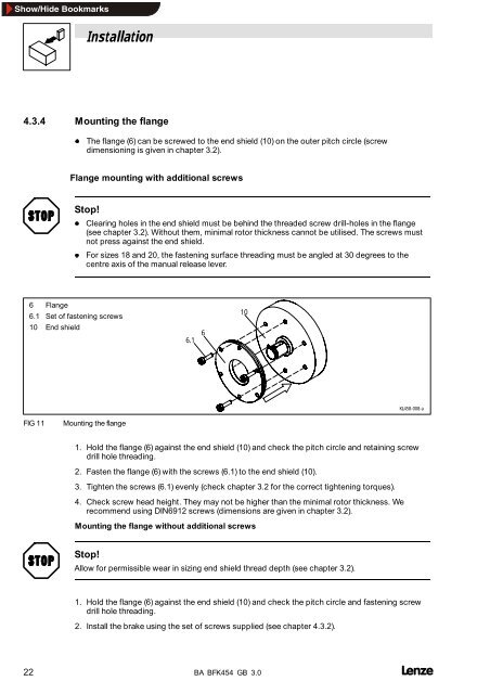
6 Flange<br />
6.1 Set of fastening screws<br />
10 End shield<br />
6.1<br />
6<br />
10<br />
KL458-008-a<br />
FIG 11<br />
Mounting the flange<br />
1. Hold the flange (6) against the end shield (10) and check the pitch circle and retaining screw<br />
drill hole threading.<br />
2. Fasten the flange (6) with the screws (6.1) to the end shield (10).<br />
3. Tighten the screws (6.1) evenly (check chapter 3.2 for the correct tightening torques).<br />
4. Check screw head height. They may not be higher than the minimal rotor thickness. We<br />
recommend using DIN6912 screws (dimensions are given in chapter 3.2).<br />
Mounting the flange without additional screws<br />
Stop!<br />
Allow for permissible wear in sizing end shield thread depth (see chapter 3.2).<br />
1. Hold the flange (6) against the end shield (10) and check the pitch circle and fastening screw<br />
drill hole threading.<br />
2. Install the brake using the set of screws supplied (see chapter 4.3.2).<br />
22 BA <strong>BFK</strong>454 GB 3.0