Protection relay software models in interaction with power system simulators
Protection relay software models in interaction with power system ...
Protection relay software models in interaction with power system ...
- No tags were found...

Create successful ePaper yourself
Turn your PDF publications into a flip-book with our unique Google optimized e-Paper software.
Power <strong>system</strong> model<br />
Power <strong>system</strong> is modelled <strong>in</strong> Simul<strong>in</strong>k environment by<br />
use of SimPowerSystem and other Simul<strong>in</strong>k library<br />
elements.<br />
SimPowerSystem is a design tool for modell<strong>in</strong>g and<br />
simulat<strong>in</strong>g electrical <strong>power</strong> <strong>system</strong>s <strong>with</strong><strong>in</strong> the Simul<strong>in</strong>k,<br />
allow<strong>in</strong>g a <strong>power</strong> <strong>system</strong> model to be built <strong>in</strong> an easy<br />
manner. It is a <strong>power</strong>ful solution for modell<strong>in</strong>g the<br />
electrical <strong>power</strong> <strong>system</strong>, especially when design<strong>in</strong>g<br />
associated control and protection <strong>system</strong>s. The library<br />
conta<strong>in</strong>s blocks that represent common components and<br />
devices found <strong>in</strong> electrical <strong>power</strong> networks. The blocks<br />
are based on well-known electro-magnetic and electromechanical<br />
equations. The libraries conta<strong>in</strong> <strong>models</strong> of<br />
typical <strong>power</strong> equipment.<br />
Distribution <strong>system</strong> is mostly modelled by common<br />
library elements <strong>with</strong> m<strong>in</strong>or modifications where<br />
necessary, as for example <strong>with</strong> arc model. Even though to<br />
Matlab is <strong>in</strong>herent slower <strong>power</strong> <strong>system</strong> simulation<br />
(compared <strong>with</strong> EMTP (ATP) [1]), this drawback is<br />
negligible s<strong>in</strong>ce the distribution model does not present<br />
large <strong>system</strong>.<br />
Measur<strong>in</strong>g (<strong>in</strong>strument) transformer <strong>models</strong><br />
Power <strong>system</strong> high voltages and currents cannot be<br />
directly applied to the <strong>relay</strong>s. Therefore, voltage (VT) and<br />
current (CT) transformers reduce <strong>power</strong> <strong>system</strong> voltages<br />
and currents. In Croatia distribution <strong>system</strong> voltages are<br />
typically reduced to the nom<strong>in</strong>al value of 100 V and<br />
currents are reduced to the nom<strong>in</strong>al value of 5 A or 1 A.<br />
Special attention has been paid to the CT modell<strong>in</strong>g<br />
regard<strong>in</strong>g the CTs DC saturation effect (noticed and<br />
recorded dur<strong>in</strong>g the earth-fault tests <strong>with</strong> resonant<br />
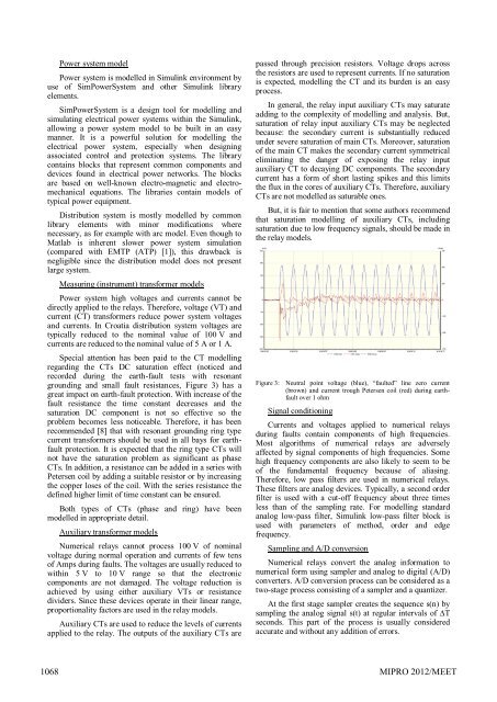
ground<strong>in</strong>g and small fault resistances, Figure 3) has a<br />
great impact on earth-fault protection. With <strong>in</strong>crease of the<br />
fault resistance the time constant decreases and the<br />
saturation DC component is not so effective so the<br />
problem becomes less noticeable. Therefore, it has been<br />
recommended [8] that <strong>with</strong> resonant ground<strong>in</strong>g r<strong>in</strong>g type<br />
current transformers should be used <strong>in</strong> all bays for earthfault<br />
protection. It is expected that the r<strong>in</strong>g type CTs will<br />
not have the saturation problem as significant as phase<br />
CTs. In addition, a resistance can be added <strong>in</strong> a series <strong>with</strong><br />
Petersen coil by add<strong>in</strong>g a suitable resistor or by <strong>in</strong>creas<strong>in</strong>g<br />
the copper loses of the coil. With the series resistance the<br />
def<strong>in</strong>ed higher limit of time constant can be ensured.<br />
Both types of CTs (phase and r<strong>in</strong>g) have been<br />
modelled <strong>in</strong> appropriate detail.<br />
Auxiliary transformer <strong>models</strong><br />
Numerical <strong>relay</strong>s cannot process 100 V of nom<strong>in</strong>al<br />
voltage dur<strong>in</strong>g normal operation and currents of few tens<br />
of Amps dur<strong>in</strong>g faults. The voltages are usually reduced to<br />
<strong>with</strong><strong>in</strong> 5 V to 10 V range so that the electronic<br />
components are not damaged. The voltage reduction is<br />
achieved by us<strong>in</strong>g either auxiliary VTs or resistance<br />
dividers. S<strong>in</strong>ce these devices operate <strong>in</strong> their l<strong>in</strong>ear range,<br />
proportionality factors are used <strong>in</strong> the <strong>relay</strong> <strong>models</strong>.<br />
Auxiliary CTs are used to reduce the levels of currents<br />
applied to the <strong>relay</strong>. The outputs of the auxiliary CTs are<br />
passed through precision resistors. Voltage drops across<br />
the resistors are used to represent currents. If no saturation<br />
is expected, modell<strong>in</strong>g the CT and its burden is an easy<br />
process.<br />
In general, the <strong>relay</strong> <strong>in</strong>put auxiliary CTs may saturate<br />
add<strong>in</strong>g to the complexity of modell<strong>in</strong>g and analysis. But,<br />
saturation of <strong>relay</strong> <strong>in</strong>put auxiliary CTs may be neglected<br />
because: the secondary current is substantially reduced<br />
under severe saturation of ma<strong>in</strong> CTs. Moreover, saturation<br />
of the ma<strong>in</strong> CT makes the secondary current symmetrical<br />
elim<strong>in</strong>at<strong>in</strong>g the danger of expos<strong>in</strong>g the <strong>relay</strong> <strong>in</strong>put<br />
auxiliary CT to decay<strong>in</strong>g DC components. The secondary<br />
current has a form of short last<strong>in</strong>g spikes and this limits<br />
the flux <strong>in</strong> the cores of auxiliary CTs. Therefore, auxiliary<br />
CTs are not modelled as saturable ones.<br />
But, it is fair to mention that some authors recommend<br />
that saturation modell<strong>in</strong>g of auxiliary CTs, <strong>in</strong>clud<strong>in</strong>g<br />
saturation due to low frequency signals, should be made <strong>in</strong><br />
the <strong>relay</strong> <strong>models</strong>.<br />
Figure 3: Neutral po<strong>in</strong>t voltage (blue), “faulted” l<strong>in</strong>e zero current<br />
(brown) and current trough Petersen coil (red) dur<strong>in</strong>g earthfault<br />
over 1 ohm<br />
Signal condition<strong>in</strong>g<br />
Currents and voltages applied to numerical <strong>relay</strong>s<br />
dur<strong>in</strong>g faults conta<strong>in</strong> components of high frequencies.<br />
Most algorithms of numerical <strong>relay</strong>s are adversely<br />
affected by signal components of high frequencies. Some<br />
high frequency components are also likely to seem to be<br />
of the fundamental frequency because of alias<strong>in</strong>g.<br />
Therefore, low pass filters are used <strong>in</strong> numerical <strong>relay</strong>s.<br />
These filters are analog devices. Typically, a second order<br />
filter is used <strong>with</strong> a cut-off frequency about three times<br />
less than of the sampl<strong>in</strong>g rate. For modell<strong>in</strong>g standard<br />
analog low-pass filter, Simul<strong>in</strong>k low-pass filter block is<br />
used <strong>with</strong> parameters of method, order and edge<br />
frequency.<br />
Sampl<strong>in</strong>g and A/D conversion<br />
Numerical <strong>relay</strong>s convert the analog <strong>in</strong>formation to<br />
numerical form us<strong>in</strong>g sampler and analog to digital (A/D)<br />
converters. A/D conversion process can be considered as a<br />
two-stage process consist<strong>in</strong>g of a sampler and a quantizer.<br />
At the first stage sampler creates the sequence s(n) by<br />
sampl<strong>in</strong>g the analog signal s(t) at regular <strong>in</strong>tervals of ∆T<br />
seconds. This part of the process is usually considered<br />
accurate and <strong>with</strong>out any addition of errors.<br />
1068 MIPRO 2012/MEET