Protection relay software models in interaction with power system simulators
Protection relay software models in interaction with power system ...
Protection relay software models in interaction with power system ...
- No tags were found...

You also want an ePaper? Increase the reach of your titles
YUMPU automatically turns print PDFs into web optimized ePapers that Google loves.
VII. RELAY LIBRARIES<br />
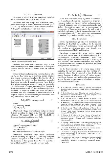
As shawn <strong>in</strong> Figure 6, several <strong>models</strong> of earth-fault<br />
<strong>relay</strong>s are modelled and stored <strong>in</strong> <strong>relay</strong> library.<br />
Modelled earth-fault <strong>relay</strong>s are: overcurrent (51N),<br />
directional voltage or current polarised directional (67N,<br />
32U or 32I), directional sensitive or wattmetric/warmetric<br />
(67Ns, 32W) and admittance earth-fault <strong>relay</strong>.<br />
Figure 6: Earth-fault <strong>relay</strong> <strong>models</strong> library<br />
Def<strong>in</strong>ite time earth-fault overcurrent <strong>relay</strong> is nondirectional<br />
<strong>relay</strong> which compares measured or from phase<br />
currents derived earth-fault current <strong>with</strong> set constant<br />
value.<br />
Inputs for traditional directional current polarised <strong>relay</strong><br />
are 3I 0 and I pol , where I pol is polaris<strong>in</strong>g current obta<strong>in</strong>ed<br />
from neutral po<strong>in</strong>t ground conductor [6]. So, this <strong>relay</strong> is<br />
only suitable for solidly or low impedance grounded<br />
distribution networks. It calculates torque (term derived<br />
from electro-mechanical <strong>relay</strong><strong>in</strong>g) based on magnitudes<br />
and relative angle of analog <strong>in</strong>put quantities, Equation 1.<br />
Relay compares the result of calculated torque aga<strong>in</strong>st set<br />
thresholds. If torque is positive and above the positive<br />
threshold, then <strong>relay</strong> determ<strong>in</strong>es a forward earth-fault. If<br />
torque is negative and below the negative threshold, then<br />
<strong>relay</strong> determ<strong>in</strong>es a reverse earth-fault.<br />
where:<br />
I pol : Polaris<strong>in</strong>g current<br />
3I 0 : = I A +I B +I C<br />
| | | | ( - ) (1)<br />
Directional voltage polarised <strong>relay</strong> makes directional<br />
decision accord<strong>in</strong>g to Equation 2. The <strong>relay</strong> compares<br />
calculated Z0 aga<strong>in</strong>st Z0F and Z0R thresholds to<br />
determ<strong>in</strong>e the direction of the ground fault.<br />
[ ]<br />
| |<br />
(2)<br />
where (* - complex conjugate):<br />
3V 0 : = V A +V B +V C<br />
3I 0 : = I A +I B +I C<br />
Θ L0 : L<strong>in</strong>e zero-sequence impedance angle<br />
Directional wattmetric <strong>relay</strong> makes directional<br />
decision accord<strong>in</strong>g to Equation 3. The <strong>relay</strong> compares<br />
calculated W aga<strong>in</strong>st -w and +w thresholds to determ<strong>in</strong>e<br />
the direction of the ground fault. W < -w <strong>in</strong>dicates a<br />
forward fault and W > +w <strong>in</strong>dicates a reverse fault.<br />
[ ⃗⃗⃗ ⃗⃗ ] (3)<br />
Earth-fault admittance <strong>relay</strong> algorithm is centralised<br />
and it simultaneously uses zero currents from all galvanic<br />
connected feeders (on the same busbar) and common zero<br />
voltage. It calculates zero asymmetry admittance for each<br />
feeder. Asymmetries occur as a consequence of<br />
asymmetries of feeder capacitances to the earth or of an<br />
earth-fault. Advantage is that it also calculates asymmetry<br />
admittance change dY. This algorithm has two thresholds,<br />
an absolute Y as_max and the sensitive one dY as_max .<br />
VIII. CONCLUSION<br />
In this paper methodology for <strong>power</strong> <strong>system</strong> and <strong>relay</strong><br />
modell<strong>in</strong>g is described <strong>in</strong> accordance to the relevant<br />
literature. A distribution <strong>system</strong> and several earth-fault<br />
<strong>relay</strong> <strong>models</strong> are developed us<strong>in</strong>g user friendly open<br />
<strong>system</strong> environment Matlab and Simul<strong>in</strong>k.<br />
Developed comprehensive <strong>relay</strong> <strong>models</strong> process<br />
voltage and current transient waveforms obta<strong>in</strong>ed from<br />
electromagnetic transients simulations, actual fault<br />
waveforms captured by numerical <strong>relay</strong>s, or from digital<br />
fault recorders. This way user can observe their response<br />
to these transients and reaffirm the protection behaviour<br />
dur<strong>in</strong>g network disturbances.<br />
In the future <strong>in</strong>tention is to develop <strong>relay</strong> <strong>software</strong><br />
modell<strong>in</strong>g for relevant test<strong>in</strong>g prior the build<strong>in</strong>g of a<br />
prototype <strong>relay</strong>s. This is essential <strong>in</strong> the development<br />
process because, it allows test<strong>in</strong>g of various <strong>relay</strong><strong>in</strong>g<br />
algorithms, the <strong>relay</strong> logic and to make necessary changes<br />
<strong>with</strong>out the need to make changes <strong>in</strong> hardware or <strong>software</strong><br />
modules of the actual device.<br />
REFERENCES<br />
[1] T. S. Sidhu et al, “Software <strong>models</strong> for use <strong>with</strong> Electromagnetic<br />
Transient Analysis Programs,” CIGRE WG B5.17 Report, Ref. No.<br />
295, 2006.<br />
[2] A. K. S. Chaudhary et al, “Model<strong>in</strong>g and analysis of transient<br />
performance of protection <strong>system</strong>s us<strong>in</strong>g digital programs,” IEEE<br />
WG Task Force Special Publication, 1998.<br />
[3] P: G. McLaren et al, “Software <strong>models</strong> for <strong>relay</strong>s,” IEEE<br />
Transactions on Power Delivery, Vol. 16, No. 2, pp. 238-246, 2001.<br />
[4] M. Kezunović, “ User-friendly, open-<strong>system</strong> <strong>software</strong> for teach<strong>in</strong>g<br />
protective <strong>relay</strong><strong>in</strong>g application and design concepts,” IEEE<br />
Transactions on Power Systems, Vol. 18, No. 3, pp. 986-992, 2003.<br />
[5] G. Sybille et al, “Theory and Applications of Power System<br />
Blockset, a MATLAB/Simul<strong>in</strong>k-Based Simulation Tool for Power<br />
Systems,” IEEE Power Eng<strong>in</strong>eer<strong>in</strong>g Society W<strong>in</strong>ter Meet<strong>in</strong>g,<br />
Vol.1, pp. 774-779, 2000.<br />
[6] J. Roberts, H. J. Altuve, D. Hou, “Review of ground fault<br />
protection methods for grounded, ungrounded and compensated<br />
distribution <strong>system</strong>s,” Technical paper, Schweitzer Eng<strong>in</strong>eer<strong>in</strong>g<br />
Laboratories, 2001.<br />
[7] A. Guzman, J. Roberts, D. Hou, “New ground directional elements<br />
operate reliably for chang<strong>in</strong>g <strong>system</strong> conditions,” 51 st Annual<br />
Protective Relay<strong>in</strong>g Conference, Atlanta, Georgia, 1997.<br />
[8] I. G. Kuliš, “Earth-fault detection methods <strong>in</strong> resonant grounded<br />
MV networks,” Study report for DSO, EIHP, 2006.<br />
[9] I. G. Kuliš et al, “Typ<strong>in</strong>g of solutions for the implementation of<br />
neutral po<strong>in</strong>t ground<strong>in</strong>g <strong>in</strong> MV networks,” Study report for DSO,<br />
Končar – Institut, 2010.<br />
[10] I. G. Kuliš et al, “The criteria for neutral po<strong>in</strong>t treatment selection<br />
<strong>in</strong> 20(10) kV radial networks <strong>in</strong> “Elektra” Zagreb,” 20 th<br />
International Conference on Electricity Distribution, CIRED,<br />
Prague, 2009.<br />
1070 MIPRO 2012/MEET