7814 Actuators SQM45... SQM48... - Delta Control
7814 Actuators SQM45... SQM48... - Delta Control
7814 Actuators SQM45... SQM48... - Delta Control

Create successful ePaper yourself
Turn your PDF publications into a flip-book with our unique Google optimized e-Paper software.
Warning notes<br />
To avoid injury to persons, damage to property or the environment, the following<br />
warning notes should be observed!<br />
Do not open, interfere with or modify the actuators!<br />
• All activities (mounting, installation and service work, etc.) must be performed by<br />
qualified staff<br />
• Before making any wiring changes in the connection area of the SQM4..., completely<br />
isolate the burner control from the mains supply (all-polar disconnection)<br />
• Ensure protection against electric shock hazard by providing adequate protection<br />
for the connection terminals and by securing the housing cover<br />
• Check to ensure that wiring is in an orderly state<br />
• Fall or shock can adversely affect the safety functions. Such units must not be put<br />
into operation, even if they do not exhibit any damage<br />
Mounting notes<br />
• Ensure that the relevant national safety regulations are complied with<br />
• The connection between actuator drive shaft and controlling element must be rigid<br />
with no mechanical play<br />
Positive connection<br />
Possible connection with drive shaft or hub:<br />
• Groove with Woodruff key<br />
• Drive shaft with flat edge and matching counterpiece<br />
To avoid inadmissible loads on bearings caused by rigid hubs, it is recommended to<br />
use compensating clutches with no mechanical play (e.g. metal bellows clutches).<br />
Cable and cable<br />
shielding<br />
Only the specified cable may be used (refer to Basic Documentation P7550). The cable’s<br />
shielding must be connected to the printed circuit board using the tab provided.<br />
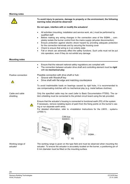
Ensure that the actuator’s housing is connected to functional earth (FE) of the system.<br />
If necessary, remove isolating layers of paint from the fixing points on the burner’s casing<br />
or run separate earth wires.<br />
For detailed information, refer to «Installation Instructions for the LMV5… system»<br />
(J7550.1).<br />
CAN bus<br />
AGG5.6...<br />
<strong>7814</strong>z03e/0502<br />
Basic unit<br />
LMV5...<br />
SQM4...<br />
FE<br />
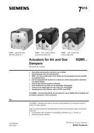
Working range of<br />
actuator<br />
The working range is given on the type field and must be observed when mounting the<br />
actuator. To ensure the actuator is accurately located on the burner, a positioning pin of<br />
6 mm diameter must be fitted on the mounting surface.<br />
2/8<br />
Siemens Building Technologies<br />
CC1N<strong>7814</strong>en<br />
HVAC Products 27.01.2005