7814 Actuators SQM45... SQM48... - Delta Control
7814 Actuators SQM45... SQM48... - Delta Control
7814 Actuators SQM45... SQM48... - Delta Control

Create successful ePaper yourself
Turn your PDF publications into a flip-book with our unique Google optimized e-Paper software.
7 814<br />
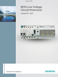
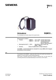
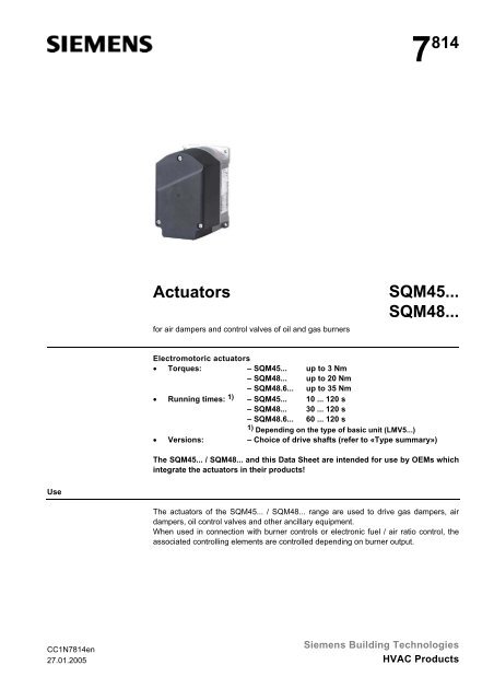
<strong>Actuators</strong><br />
for air dampers and control valves of oil and gas burners<br />
<strong>SQM45.</strong>..<br />
<strong>SQM48.</strong>..<br />
Electromotoric actuators<br />
• Torques: – <strong>SQM45.</strong>.. up to 3 Nm<br />
– <strong>SQM48.</strong>.. up to 20 Nm<br />
– <strong>SQM48.</strong>6... up to 35 Nm<br />
• Running times: 1) – <strong>SQM45.</strong>.. 10 ... 120 s<br />
– <strong>SQM48.</strong>.. 30 ... 120 s<br />
– <strong>SQM48.</strong>6... 60 ... 120 s<br />
1) Depending on the type of basic unit (LMV5...)<br />
• Versions: – Choice of drive shafts (refer to «Type summary»)<br />
The <strong>SQM45.</strong>.. / <strong>SQM48.</strong>.. and this Data Sheet are intended for use by OEMs which<br />
integrate the actuators in their products!<br />
Use<br />
The actuators of the <strong>SQM45.</strong>.. / <strong>SQM48.</strong>.. range are used to drive gas dampers, air<br />
dampers, oil control valves and other ancillary equipment.<br />
When used in connection with burner controls or electronic fuel / air ratio control, the<br />
associated controlling elements are controlled depending on burner output.<br />
CC1N<strong>7814</strong>en<br />
27.01.2005<br />
Siemens Building Technologies<br />
HVAC Products
Warning notes<br />
To avoid injury to persons, damage to property or the environment, the following<br />
warning notes should be observed!<br />
Do not open, interfere with or modify the actuators!<br />
• All activities (mounting, installation and service work, etc.) must be performed by<br />
qualified staff<br />
• Before making any wiring changes in the connection area of the SQM4..., completely<br />
isolate the burner control from the mains supply (all-polar disconnection)<br />
• Ensure protection against electric shock hazard by providing adequate protection<br />
for the connection terminals and by securing the housing cover<br />
• Check to ensure that wiring is in an orderly state<br />
• Fall or shock can adversely affect the safety functions. Such units must not be put<br />
into operation, even if they do not exhibit any damage<br />
Mounting notes<br />
• Ensure that the relevant national safety regulations are complied with<br />
• The connection between actuator drive shaft and controlling element must be rigid<br />
with no mechanical play<br />
Positive connection<br />
Possible connection with drive shaft or hub:<br />
• Groove with Woodruff key<br />
• Drive shaft with flat edge and matching counterpiece<br />
To avoid inadmissible loads on bearings caused by rigid hubs, it is recommended to<br />
use compensating clutches with no mechanical play (e.g. metal bellows clutches).<br />
Cable and cable<br />
shielding<br />
Only the specified cable may be used (refer to Basic Documentation P7550). The cable’s<br />
shielding must be connected to the printed circuit board using the tab provided.<br />
Ensure that the actuator’s housing is connected to functional earth (FE) of the system.<br />
If necessary, remove isolating layers of paint from the fixing points on the burner’s casing<br />
or run separate earth wires.<br />
For detailed information, refer to «Installation Instructions for the LMV5… system»<br />
(J7550.1).<br />
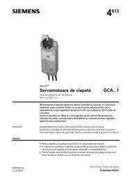
CAN bus<br />
AGG5.6...<br />
<strong>7814</strong>z03e/0502<br />
Basic unit<br />
LMV5...<br />
SQM4...<br />
FE<br />
Working range of<br />
actuator<br />
The working range is given on the type field and must be observed when mounting the<br />
actuator. To ensure the actuator is accurately located on the burner, a positioning pin of<br />
6 mm diameter must be fitted on the mounting surface.<br />
2/8<br />
Siemens Building Technologies<br />
CC1N<strong>7814</strong>en<br />
HVAC Products 27.01.2005
IP 54<br />
M15 glands<br />
To ensure degree of protection IP 54, suitable Pg11 glands must be fitted in the actuator’s<br />
Pg11 openings.<br />
The Pg glands used must feature cable strain relief.<br />
To ensure degree of protection IP 54 during the actuator’s entire service life, the bearing<br />
of the drive shaft must be located such that it will not be directly exposed to water or<br />
dust.<br />
Mid-2005, Pg11 glands will be replaced by M16 glands!<br />
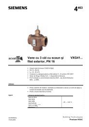
Mounting example<br />
SQM4...<br />
Spacer<br />
Mounting plate SQM4...<br />
Mounting plate VKF41...<br />
Secure coupling piece to drive shaft<br />
such that intermediate plastic<br />
piece has an axial play of about<br />
0.2 to 0.5 mm<br />
ASK33.4<br />
VKF41...<br />
<strong>7814</strong>z02e/0502<br />
Installation notes<br />
• Always run the high-voltage ignition cables separate from the unit and other cables<br />
while observing the greatest possible distance<br />
• To ensure protection against electric shock hazard, make certain that the AC 230 V<br />
section of the SQM4... is strictly segregated from the functional low-voltage section<br />
• The holding torque is reduced when the actuator’s power supply is switched off<br />
Housing cover<br />
ESD<br />
Addressing<br />
Cable length<br />
Topology<br />
The housing cover may only be removed for short periods of time for wiring or when<br />
making the addressing. It must be made certain that dust or dirt will not get inside the<br />
actuator while such work is carried out.<br />
The actuator contains a printed circuit board with ESD-sensitive components.<br />
The top side of the board carries a cover which affords protection against direct contact.<br />
This protective cover must not be removed! The underside side of the board must<br />
not be touched.<br />
Addressing (assignment of functions) defines whether the SQM4... shall operate as a<br />
• fuel actuator<br />
• air damper actuator, or<br />
• auxiliary actuator,<br />
and is made with the display and operating unit AZL5... and the addressing button on<br />
the actuator, which is located under the housing cover (refer to Basic Documentation<br />
P7550).<br />
The correct assignment of actuator functions can be checked with the help of flashing<br />
LEDs.<br />
For the maximum permissible cable length, refer to the Basic Documentation.<br />
Cabling must be strictly serial (no branching permitted!).<br />
Commissioning notes<br />
• Prior to commissioning the plant, check to ensure that wiring is in an orderly state<br />
3/8<br />
Siemens Building Technologies<br />
CC1N<strong>7814</strong>en<br />
HVAC Products 27.01.2005
Standards and certificates<br />
Conformity to EEC directives<br />
- Electromagnetic compatibility EMC (immunity)<br />
- Directive for gas appliances<br />
- Low-voltage directive<br />
89 / 336 EEC<br />
90 / 396 EEC<br />
73 / 23 EEC<br />
ISO 9001: 2000<br />
Cert. 00739<br />
ISO 14001: 1996<br />
Cert. 38233<br />
Service notes<br />
• Each time an actuator has been replaced, check to ensure that wiring is in an orderly<br />
state<br />
Replacement<br />
When replacing an actuator, the following points must be checked and, if necessary,<br />
corrected:<br />
• Addressing (assignment of functions)<br />
• Bus termination<br />
• Adjustment of the curvepoints of electronic fuel / air ratio control (e.g. with the<br />
LMV5...)<br />
Disposal notes<br />
The actuator contains electrical and electronic components and must not be disposed<br />
of together with domestic waste.<br />
Local and currently valid legislation must be observed.<br />
Mechanical design<br />
Housing<br />
The housing is made of die-cast aluminium.<br />
The cover is made of impact-proof and heat-resistant plastic.<br />
Color of cover: Black<br />
Actuator<br />
Adjustment of switching<br />
points / position<br />
indication<br />
Electrical connections<br />
Geartrain<br />
Drive shaft<br />
Mounting and fixing<br />
Stepper motor<br />
In connection with the basic unit (e.g. LMV5...): Via the display and operating unit<br />
AZL5… (refer to Basic Documentation P7550).<br />
RAST3.5 terminals (supplied together with the AGG5.720 / AGG5.721).<br />
<strong>SQM45.</strong>..: Spur gears made of plastic with small backlash and permanent lubrication.<br />
<strong>SQM48.</strong>..: Spur gears made of steel with small backlash and permanent lubrication.<br />
Made of black-finished steel, ready fitted to the front of the gear train (<strong>SQM48.</strong>.. uses a<br />
drive shaft made of hardened steel).<br />
The front of the gear train is used as the mounting surface. The actuator has 4 fixing<br />
holes and 1 elongated hole for the positioning pin.<br />
Alternatively, the actuator can be secured from the side of the controlling element with<br />
3 self-tapping screws.<br />
4/8<br />
Siemens Building Technologies<br />
CC1N<strong>7814</strong>en<br />
HVAC Products 27.01.2005
Type summary<br />
<strong>Actuators</strong> SQM4...<br />
Type reference<br />
Drive shaft<br />
1)<br />
Running time<br />
(min.)<br />
for 90°<br />
Nominal<br />
torque<br />
(max.)<br />
Holding<br />
torque 2)<br />
(max.)<br />
Radial bearing<br />
force<br />
(max.)<br />
no.<br />
s<br />
Nm<br />
Nm<br />
N<br />
<strong>SQM45.</strong>291A9 1 10 3 3) 4) 1.5 190<br />
<strong>SQM45.</strong>295A9 5 10 3 3) 4) 1.5 190<br />
<strong>SQM48.</strong>497A9 7 30 20 3) 4) 20 420<br />
<strong>SQM48.</strong>697A9 7 60 35 3) 4) 35 800<br />
Legend<br />
1) Refer to «Dimensions» 4) Under nominal conditions 20 °C. Under extreme<br />
2) With operating voltage applied conditions (above +50 °C ambient temperature), the<br />
3) Under nominal conditions 20 °C. Under extreme conditions<br />
(below –15 °C ambient temperature), the available<br />
torque is about 15 % lower<br />
torque is about 15 % lower<br />
Ordering<br />
When ordering, please give type references of actuator and accessories according to<br />
«Type summary».<br />
In addition to the actuator, the following item is to be ordered separately and is also<br />
supplied as a separate item:<br />
• Shielded cable<br />
• Special terminals RAST3.5 as part of the AGG5.720 / AGG5.721 kit<br />
Accessories<br />
Accessories must be ordered as separate items.<br />
Adapter for gas valves VKF41...C<br />
ASK33.4<br />
CAN bus connecting cable<br />
- Shielded 5-core cable, 500 m<br />
- Refer to Basic Documentation on LMV5… (P7550)<br />
AGG5.630<br />
CAN bus connecting cable<br />
- Shielded 5-core cable, 100 m<br />
- Refer to Basic Documentation on LMV5... (P7550)<br />
AGG5.631<br />
Separable cable entry (single packing)<br />
Separable cable entry (packed in sets of 50)<br />
AGG5.810<br />
AGG5.812<br />
Specified connecting cables are mandatory!<br />
5/8<br />
Siemens Building Technologies<br />
CC1N<strong>7814</strong>en<br />
HVAC Products 27.01.2005
Technical data<br />
Actuator<br />
Environment conditions<br />
Operating voltage<br />
AC 2 x 12 V via bus cable from the basic<br />
unit or via a separate transformer<br />
Safety class<br />
extra low-voltage with safe isolation from<br />
mains voltage<br />
Power consumption<br />
- <strong>SQM45.</strong>..<br />
9...15 VA<br />
- <strong>SQM48.</strong>..<br />
26...34 VA<br />
On time<br />
50 %, max. 3 min. continuously<br />
Angular adjustment max. 90°<br />
Mounting position<br />
optional<br />
Degree of protection<br />
to EN 60 529, IP 54, provided adequate<br />
cable entries are used<br />
Cable entry<br />
<strong>SQM45.</strong>.. / <strong>SQM48.</strong>..:<br />
insertable threaded cable glands for<br />
2 x Pg11<br />
from mid-2005: 2 x M16 (replacement)<br />
Electrical connections<br />
RAST3.5 terminals<br />
(for details, refer to the basic unit)<br />
Ferrules<br />
matching the dia. of the stranded wire<br />
Direction of rotation<br />
can be selected on the basic unit<br />
Torques and holding torques<br />
refer to «Type summary»<br />
Reproducibility (typically in the show-room ± 0.2° (when used with the basic unit<br />
condition)<br />
LMV5...)<br />
Running times<br />
refer to «Type summary» (can be selected<br />
on the basic unit)<br />
Load changes with continuous heavy loads<br />
- <strong>SQM45.</strong>.. / <strong>SQM48.</strong>497<br />
- <strong>SQM48.</strong>697<br />
typically 500,000<br />
typically 300,000<br />
Weight<br />
- <strong>SQM45.</strong>..<br />
- <strong>SQM48.</strong>..<br />
Direction of rotation (when facing the shaft)<br />
- Standard<br />
- Reverse<br />
approx. 1 kg<br />
approx. 1.6 kg<br />
counterclockwise<br />
clockwise<br />
Storage DIN EN 60721-3-1<br />
Climatic conditions<br />
class 1K3<br />
Mechanical conditions<br />
class 1M2<br />
Temperature range -20...+60 °C<br />
Humidity<br />
< 95 % r.h.<br />
Transport<br />
DIN EN 60 721-3-2<br />
Climatic conditions<br />
class 2K2<br />
Mechanical conditions<br />
class 2M2<br />
Temperature range<br />
-20...+70 °C<br />
Humidity<br />
< 95 % r.h.<br />
Operation<br />
Climatic conditions<br />
Mechanical conditions<br />
Temperature range<br />
Humidity<br />
DIN EN 60 721-3-3<br />
class 3K3<br />
class 3M3<br />
-20...+60 °C<br />
< 95 % r.h.<br />
Condensation, formation of ice and ingress of water are not permitted!<br />
6/8<br />
Siemens Building Technologies<br />
CC1N<strong>7814</strong>en<br />
HVAC Products 27.01.2005
Function<br />
The <strong>SQM45.</strong>.. / <strong>SQM48.</strong>.. are of robust design and have a gear train with only small backlash.<br />
<strong>Control</strong> and position feedback take place via a bus system (CAN).<br />
The bus cable is also used for powering the actuators.<br />
The actuators are driven by stepper motors and can be positioned with a resolution of<br />
0.1°.<br />
The characteristics and settings (running time, direction of rotation, limit positions) of<br />
the SQM4... are determined by the controlling basic unit (e.g. LMV5...; for details, refer<br />
to the Basic Documentation P7550 of the LMV5...).<br />
The running times of the associated controlling elements are varied by the basic unit<br />
depending on the burner’s control phase (e.g. startup phase: short running time; operation:<br />
long running time).<br />
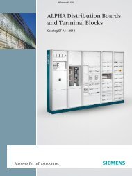
Terminating resistor<br />
At the end of the serial bus cabling, a terminating resistor must be fitted.<br />
For that purpose, a jumper must be set to BUS TERMINATION on the last actuator of<br />
the bus cable, which will activate the resistor.<br />
On all the other actuators, that jumper must be set to the other position (deactivated).<br />
Addressing button<br />
LED (function code)<br />
Jumper<br />
Bus<br />
termination<br />
Assignment of terminals<br />
12VAC1<br />
12VAC2<br />
CANH<br />
CANL<br />
GND<br />
X1<br />
12VAC1<br />
12VAC2<br />
CANH<br />
CANL<br />
GND<br />
X2<br />
<strong>7814</strong>z01e/1002<br />
The 2 terminal blocks (X1 and X2) are identical.<br />
7/8<br />
Siemens Building Technologies<br />
CC1N<strong>7814</strong>en<br />
HVAC Products 27.01.2005
0<br />
0<br />
Dimensions<br />
Dimensions in mm<br />
<strong>SQM45.</strong>.. / <strong>SQM48.</strong>..<br />
15<br />
2<br />
116<br />
90<br />
76<br />
ø5,4<br />
12<br />
ø10<br />
0<br />
+0,05<br />
6<br />
<strong>SQM45.</strong>..<br />
ø16<br />
h8<br />
ø10<br />
33<br />
+0,1<br />
2.5<br />
N9<br />
3<br />
25 41<br />
1<br />
Groove for<br />
Woodruff key<br />
3x3.7 DIN 6888<br />
87<br />
50<br />
Prepared for self-tapping<br />
screws M5, 10 mm deep, toDIN 7500<br />
<strong>7814</strong>m01e/0205<br />
+0,1<br />
6 0<br />
1<br />
h9<br />
ø10<br />
5<br />
D-shaft<br />
P9<br />
5<br />
+0.1<br />
1.9<br />
7<br />
ø14<br />
h8<br />
137<br />
122<br />
6<br />
1,5<br />
<strong>SQM45.</strong>..<br />
ø16<br />
22<br />
17<br />
47<br />
2 x Pg11<br />
(from mid-2005:<br />
2 x M16 (replacement))<br />
25,5<br />
8.5 0<br />
-0.05<br />
25<br />
ø18<br />
Groove for<br />
parallel key A5x3x28<br />
to DIN 6885 T3<br />
<strong>SQM48.</strong>..<br />
36<br />
39<br />
2 28<br />
8/8<br />
© 2005 Siemens Building Technologies Production GmbH<br />
Subject to change!<br />
Siemens Building Technologies<br />
CC1N<strong>7814</strong>en<br />
HVAC Products 27.01.2005