ALPHA Distribution Boards and Terminal Blocks
ALPHA 400 - DIN Wall-Mounted Distribution Boards - Delta Control
ALPHA 400 - DIN Wall-Mounted Distribution Boards - Delta Control
- No tags were found...

You also want an ePaper? Increase the reach of your titles
YUMPU automatically turns print PDFs into web optimized ePapers that Google loves.
© Siemens AG 2010<br />
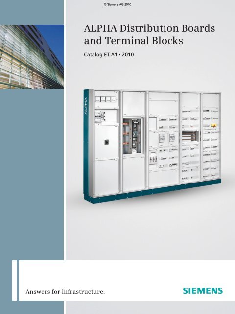
<strong>ALPHA</strong> <strong>Distribution</strong> <strong>Boards</strong><br />
<strong>and</strong> <strong>Terminal</strong> <strong>Blocks</strong><br />
Catalog ET A1 • 2010<br />
Answers for infrastructure.
© Siemens AG 2010<br />
Related catalogs<br />
Contents<br />
<strong>ALPHA</strong> <strong>Distribution</strong> <strong>Boards</strong> <strong>and</strong> <strong>Terminal</strong><br />
<strong>Blocks</strong><br />
Order No.:<br />
PDF only: (E86060-K8210-A101-B2-7600)<br />
<strong>ALPHA</strong> 400-ZS Meter Cabinets<br />
Order No.:<br />
Regional catalogs available on request<br />
(available in German only)<br />
ET A1<br />
ET A2<br />
<strong>ALPHA</strong> SIMBOX Small <strong>Distribution</strong> <strong>Boards</strong> · <strong>ALPHA</strong> 160 - DIN<br />
Wall-Mounted <strong>Distribution</strong> <strong>Boards</strong> · <strong>ALPHA</strong> 400 - DIN Wall-<br />
Mounted <strong>Distribution</strong> <strong>Boards</strong> · <strong>ALPHA</strong> 630 - DIN Floor-Mounted<br />
<strong>Distribution</strong> <strong>Boards</strong> · <strong>ALPHA</strong> AS Modular Cabinets · <strong>ALPHA</strong><br />
400-ZS Meter Cabinets · <strong>ALPHA</strong> BOX · <strong>ALPHA</strong> 8HP Molded-<br />
Plastic <strong>Distribution</strong> Systems · <strong>ALPHA</strong> SELECT Planning <strong>and</strong><br />
Configuration · <strong>ALPHA</strong> FIX <strong>Terminal</strong> <strong>Blocks</strong>: Screw <strong>Terminal</strong>s,<br />
Spring-Type <strong>Terminal</strong>s, iPo Plug-In <strong>Terminal</strong>s, Plug-In <strong>Terminal</strong>s,<br />
Combination Plug-In <strong>Terminal</strong>s, Insulation Displacement<br />
<strong>Terminal</strong>s, Accessories<br />
Region Z1 · Region Z2 · Region Z3 · Region Z4<br />
BETA Low-Voltage Circuit<br />
Protection<br />
Order No.:<br />
PDF only: (E86060-K8220-A101-B3-7600)<br />
GAMMA Building Management<br />
Systems<br />
Order No.:<br />
PDF only: (E86060-K8230-A101-B3-7600)<br />
DELTA Switches <strong>and</strong> Socket Outlets<br />
Order No.:<br />
PDF only: (E86060-K8240-A101-B3-7600)<br />
The Offline Mall<br />
Order No.:<br />
E86060-D4001-A510-C8-7600<br />
ET B1<br />
ET G1<br />
ET D1<br />
CA 01<br />
Contactors: Miniature Circuit Breakers · Residual Current<br />
Protective Devices · Low-Voltage Fuse Systems · SITOR<br />
Semiconductor Fuses · SR60 Busbar Systems · Overvoltage<br />
Protection Devices<br />
Switching: Switches <strong>and</strong> Light Indicators · Switching Devices ·<br />
Timers · Transformers, Bells <strong>and</strong> Socket Outlets<br />
Measuring: Three-Phase Measuring Devices · Single-Phase<br />
Measuring Devices<br />
Monitoring: Monitoring of Electrical Values · Monitoring of<br />
Plants <strong>and</strong> Devices<br />
Display, Operation · Output Devices · Input Devices · Combination<br />
Devices · Lighting · Sun Protection, Anti-Glare Protection,<br />
Utilization of Daylight · Heating, Cooling, Ventilation,<br />
Air-Conditioning · Load Management · Safety · Quick-<br />
Assembly Systems · Gateways, Interface Converters · Physical<br />
Sensors · Control <strong>and</strong> Automation Devices · System Products<br />
· System Accessories · Counters · GAMMA wave<br />
i-system · DELTA line · DELTA vita · DELTA miro · DELTA profil<br />
· DELTA style · DELTA natur · m-system · Surface-Mounting<br />
Product Range · Switching/Pushbutton Control/Dimming ·<br />
Motion Detectors · Shutter/Blind Controls · Room Temperature<br />
Controllers · Data <strong>and</strong> Communication Systems · Remote<br />
Control Systems · Smoke Detectors · GAMMA Bus Coupling<br />
Units<br />
All products of automation, drives <strong>and</strong> installation technology,<br />
including those in the catalogs listed above.<br />
The Online Mall<br />
Internet:<br />
www.siemens.com/automation/mall<br />
All products of automation, drives <strong>and</strong> installation technology,<br />
including those in the catalogs listed above.<br />
Catalog PDF<br />
Internet:<br />
www.automation.siemens.com/infocenter<br />
All catalogs for electrical installation technology can be downloaded<br />
as PDF files.<br />
Trademarks<br />
All product designations may be registered trademarks or<br />
product names of Siemens AG or other supplying<br />
companies. Third parties using these trademarks or product<br />
names for their own purposes may infringe upon the rights of<br />
the trademark owners.<br />
Further information about electrical installation is available on<br />
the Internet at:<br />
www.siemens.com/et<br />
Technical Assistance<br />
Expert technical assistance for<br />
Low-voltage controls <strong>and</strong> electrical<br />
installation.<br />
Tel.: +49 (0) 180 5050 222 *<br />
Fax: +49 (0) 180 5050 223 *<br />
E-mail: support.<br />
automation@siemens.com<br />
* € 0.14/minute from a German<br />
l<strong>and</strong>line, call charges from<br />
mobile phones may vary<br />
Siemens ET A1 · 10/2009
<strong>ALPHA</strong> <strong>Distribution</strong> <strong>Boards</strong> <strong>and</strong><br />
<strong>Terminal</strong> <strong>Blocks</strong><br />
Catalog ET A1 · 2010<br />
© Siemens AG 2010<br />
The products <strong>and</strong><br />
systems listed in this<br />
catalog are developed<br />
<strong>and</strong> manufactured in<br />
accordance with a<br />
VDE-certified quality<br />
management system<br />
complying with<br />
EN ISO 9001:2000.<br />
<strong>Distribution</strong> <strong>Boards</strong><br />
<strong>ALPHA</strong> SIMBOX Small <strong>Distribution</strong><br />
<strong>Boards</strong><br />
SIMBOX 63, SIMBOX LC, SIMBOX WP<br />
1<br />
<strong>ALPHA</strong> 160 - DIN Wall-Mounted<br />
<strong>Distribution</strong> <strong>Boards</strong> 2<br />
<strong>ALPHA</strong> 400 - DIN Wall-Mounted<br />
<strong>Distribution</strong> <strong>Boards</strong> 3<br />
<strong>ALPHA</strong> 630 - DIN Floor-Mounted<br />
<strong>Distribution</strong> <strong>Boards</strong> 4<br />
<strong>ALPHA</strong> AS Modular <strong>Distribution</strong><br />
<strong>Boards</strong> 5<br />
<strong>ALPHA</strong> 400-ZS Meter Cabinets<br />
<strong>ALPHA</strong> BOX<br />
6<br />
7<br />
<strong>ALPHA</strong> 8HP Molded-Plastic<br />
<strong>Distribution</strong> Systems 8<br />
Planning <strong>and</strong> Configuration<br />
9<br />
Supersedes:<br />
Catalog ET A1 · 2009/2010<br />
Refer to the Industry Mall for current updates<br />
of this catalog<br />
www.siemens.com/automation/mall<br />
The products in this catalog can also be found<br />
in the electronic catalog CA 01.<br />
Order No.:<br />
E86060-D4001-A510-C8-7600<br />
Contact your local Siemens sales office<br />
for further information.<br />
© Siemens AG 2009<br />
<strong>ALPHA</strong> FIX <strong>Terminal</strong> <strong>Blocks</strong><br />
Screw <strong>Terminal</strong>s<br />
10<br />
<strong>Terminal</strong>s with Spring-Loaded<br />
Connection 11<br />
iPo Plug-In <strong>Terminal</strong>s N<br />
Plug-In <strong>Terminal</strong>s<br />
Combination Plug-In <strong>Terminal</strong>s<br />
Insulation Displacement <strong>Terminal</strong>s<br />
12<br />
13<br />
14<br />
15<br />
Appendix<br />
Accessories for <strong>Terminal</strong> <strong>Blocks</strong><br />
16<br />
17
© Siemens AG 2010<br />
Innovation is the key to success.<br />
We continue to invest heavily in the research<br />
<strong>and</strong> development of new technologies.<br />
We have our own experimental <strong>and</strong><br />
test laboratories where we carry out intensive<br />
basic research on the climate in<br />
buildings <strong>and</strong> on fire, gas <strong>and</strong> explosion<br />
protection. This gives us the experience<br />
<strong>and</strong> the opportunity to create solutions<br />
that continuously flow into our new products<br />
<strong>and</strong> systems. At special test premises,<br />
such as airport buildings <strong>and</strong> hospitals,<br />
we test the interoperability of the individual<br />
systems. This empirical data is incorporated<br />
into industry-specific solutions<br />
that continually set new st<strong>and</strong>ards <strong>and</strong><br />
underscore our claim to technological<br />
leadership.<br />
Energy-efficiency <strong>and</strong> environmental<br />
protection is our business principle.<br />
And this business principle applies crosscompany<br />
<strong>and</strong> to each <strong>and</strong> every employee:<br />
We are committed to environmental<br />
protection <strong>and</strong> the careful use of resources.<br />
Since 1994, we have been<br />
involved in more than 1300 energy efficiency<br />
projects, which have jointly contributed<br />
to the saving of around 1.5 billion<br />
euros in energy costs <strong>and</strong> reduced the annual<br />
CO 2 burden on the environment by<br />
approx. 700,000 t. So it’s obvious that intelligent<br />
solutions in technical infrastructures<br />
benefit not only the owners <strong>and</strong> operators<br />
of buildings, but also those who<br />
have nothing to do with them.<br />
Close customer relations are our USP.<br />
This is not just a soundbite. We make every<br />
effort to ensure close customer relations.<br />
We have in-depth knowledge of<br />
their business <strong>and</strong> involve them in the development<br />
of our innovations. Our skills<br />
make us an expert provider of industryspecific<br />
solutions <strong>and</strong> services, a preferred<br />
partner during the life cycle of a building -<br />
<strong>and</strong> allow us to enjoy mutual growth with<br />
our customers.<br />
2 Siemens ET A1 · 10/2009
© Siemens AG 2010<br />
Answers for Infrastructure.<br />
Siemens Industry meets the great challenges of our time<br />
head on. With solutions for technical infrastructure in<br />
industrial <strong>and</strong> non-residential buildings, residential<br />
buildings <strong>and</strong> public facilities, Siemens ensures enhanced<br />
comfort <strong>and</strong> energy efficiency in buildings, as well as the<br />
protection <strong>and</strong> safety of persons, property <strong>and</strong> business<br />
processes. As a longst<strong>and</strong>ing <strong>and</strong> professional partner with<br />
all-round expertise in the industry sector, we offer tailored<br />
solutions that generate sustainable added value for our<br />
customers.<br />
Gain a competitive edge - with integrated building solutions.<br />
Total Building Solutions means more innovation<br />
from a single source for enhanced<br />
functionality under one roof.<br />
When it comes to delivering turnkey buildings<br />
equipped with cutting edge power<br />
distribution, building automation <strong>and</strong><br />
safety <strong>and</strong> fire-protection equipment from<br />
a single source, Siemens is in a league of<br />
its own. And just to show that we are<br />
more than the sum of our parts, our portfolio<br />
includes:<br />
• Electrical installation<br />
<strong>Distribution</strong> boards <strong>and</strong> terminal<br />
blocks, low-voltage circuit protection,<br />
building management systems,<br />
switches <strong>and</strong> socket outlets<br />
• Building automation<br />
Heating, ventilation <strong>and</strong> air-conditioning<br />
controls, overall energy solutions<br />
offering guaranteed savings<br />
• Safety solutions<br />
Access control, video monitoring, burglar<br />
protection, alarm control centers,<br />
operation of alarm control centers<br />
• Fire protection<br />
Fire alarms, alerting, evacuation,<br />
extinction <strong>and</strong> complete fire protection<br />
solutions<br />
Take a closer look at all the options available<br />
from Siemens. Check out the opportunities<br />
our products provide <strong>and</strong> discover<br />
how we can help you sustainably enhance<br />
your competitive edge.<br />
Siemens ET A1 · 10/2009<br />
3
© Siemens AG 2010<br />
Electrical Installation from A to Z<br />
<strong>ALPHA</strong> <strong>Distribution</strong> <strong>Boards</strong> <strong>and</strong> <strong>Terminal</strong> <strong>Blocks</strong><br />
The <strong>ALPHA</strong> range comprises small distribution boards, meter<br />
cabinets, distribution boards <strong>and</strong> molded-plastic distribution<br />
boards. The <strong>ALPHA</strong> FIX terminal blocks meet all your needs for<br />
clear <strong>and</strong> manageable wiring using a full range of connection<br />
systems.<br />
BETA Low-Voltage Circuit Protection<br />
Siemens is the only manufacturer to offer an all-round protection<br />
concept with an optimally coordinated device range for<br />
line protection, personal <strong>and</strong> fire protection, lightning <strong>and</strong><br />
overvoltage protection, <strong>and</strong> device <strong>and</strong> system protection.<br />
Switching, measuring <strong>and</strong> monitoring devices complete our<br />
low-voltage circuit protection offering. Based on an all-round<br />
protection concept, our device range offers a complete<br />
spectrum of protection devices, such as fuses, miniature circuit<br />
breakers, residual current protective devices <strong>and</strong> overvoltage<br />
protection devices, as well as switching devices, measuring instruments<br />
<strong>and</strong> monitoring devices.<br />
GAMMA Building Management Systems<br />
Buildings should be energy efficient <strong>and</strong> allow quick <strong>and</strong> costeffective<br />
adaptation to user requirements. Lighting, sun<br />
protection <strong>and</strong> indoor environment should be achieved in an<br />
energy-saving <strong>and</strong> user-friendly manner, while persons <strong>and</strong><br />
property are protected against hazards <strong>and</strong> damage. The tried<br />
<strong>and</strong> tested GAMMA instabus building system engineering<br />
supports the flexible networking of electrical devices <strong>and</strong> functions<br />
in buildings over two wires of the bus cable <strong>and</strong> connection<br />
to building management systems over KNXnet/IP – thus<br />
providing greater efficiency, safety, flexibility <strong>and</strong> comfort.<br />
DELTA Switches <strong>and</strong> Socket Outlets<br />
The DELTA switch <strong>and</strong> socket outlet range combines a wide<br />
range of different design interfaces with more innovative <strong>and</strong><br />
safer technology. And because the user interfaces are simple to<br />
interchange, you can enjoy complete safety – even when your<br />
taste or the environment changes.<br />
4 Siemens ET A1 · 10/2009
© Siemens AG 2010<br />
Modern Electrical Low-Voltage Control <strong>and</strong> Installation<br />
Technology<br />
These days it's hard to imagine daily life without electricity.<br />
Modern electrical switching <strong>and</strong> installation technology is an<br />
essential requirement for ensuring that our use of electricity is<br />
safe <strong>and</strong> user-friendly.<br />
Shaping the Future with Innovations<br />
It is a fact of life that there can be no progress without innovation<br />
- which is why we make every endeavor to continue producing<br />
innovations in the area of electrical installation technology,<br />
as well as improving existing products <strong>and</strong><br />
developing new applications. Our mission is to offer innovative<br />
<strong>and</strong> high-quality products across the whole spectrum of<br />
electrical installation technology in order to further increase<br />
our competitive edge <strong>and</strong> open up new market opportunities.<br />
Industry<br />
Our Factory in Regensburg <strong>and</strong> our Branches Worldwide<br />
Siemens has been developing products <strong>and</strong> innovative<br />
solutions for industry <strong>and</strong> for residential <strong>and</strong> non-residential<br />
buildings since 1883. While production began in Berlin, our<br />
production has now been based in Regensburg for the last<br />
60 years. Today, this factory is one of the key international<br />
manufacturers of installation technology. Our cutting edge<br />
equipment includes: CAD, simulation <strong>and</strong> automated laboratory<br />
equipment.<br />
Non-residential buildings<br />
We now have more than 20 production sites in Europe, Asia<br />
<strong>and</strong> America - which is the best way to ensure compliance<br />
with country-specific st<strong>and</strong>ards – <strong>and</strong> the best way to ensure<br />
that our customers enjoy local support.<br />
Residential buildings<br />
Siemens ET A1 · 10/2009<br />
5
© Siemens AG 2010<br />
Quality <strong>and</strong> the Environment<br />
Quality in the Context of the Environment<br />
Increasing urbanization <strong>and</strong> a growing global population have<br />
meant that it has become one of our key challenges to look<br />
after <strong>and</strong> preserve our natural resources – one we are happy<br />
to meet head on.<br />
Acting Responsibly<br />
As part of the ecologically responsible <strong>and</strong> globally active<br />
Siemens Group, we are setting the bar high. Our environmental<br />
protection objectives are an integral part of our rigorous<br />
quality management.<br />
Even during the development of our products <strong>and</strong> systems,<br />
we take a critical look at their possible effects on the environment.<br />
So, without exception, they all comply with the EC<br />
Directive RoHS (Restriction of Hazardous Substances). During<br />
this development phase, we also lay the foundations for the<br />
highest quality: we define reliability requirements <strong>and</strong> the related<br />
quality assurance measures from the outset - <strong>and</strong> incorporate<br />
them into all drafts.<br />
Pro-Active Environmental Protection<br />
It goes without saying that we are certified to ISO 14001 – as<br />
are all Siemens premises. Furthermore, as an active member<br />
of ZVEI (German Electrical <strong>and</strong> Electronic Manufacturers' Association),<br />
we pro-actively support the protection of the environment<br />
with a wide range of measures, such as the development<br />
of binding environmental management systems.<br />
In 2006 – following previous awards in 1995, 1999 <strong>and</strong> 2002<br />
– our factory in Regensburg was presented with its fourth Environmental<br />
Award of the City of Regensburg for its strong<br />
commitment to environmental issues. This latest prize was<br />
awarded for the fact that we have voluntarily renounced the<br />
use of hazardous substances in our products <strong>and</strong> for our consistent<br />
application of this aim in our galvanic processes.<br />
All products <strong>and</strong> systems are also subject to strict quality<br />
specifications during production <strong>and</strong> testing. We take great<br />
care to ensure compliance with these specifications in order to<br />
guarantee our customers nothing but the very best quality.<br />
Our many certificates bear witness to our success.<br />
Pioneers in recycling<br />
As a founder member of a non-profit association for the active<br />
promotion of the environment-friendly recycling of disabled<br />
LV HRC fuse links, Siemens takes a pro-active approach to recycling.<br />
The aim of the association is to create a voluntary<br />
system for the environment-friendly recycling of LV HRC fuse<br />
links, which is simple <strong>and</strong> free for participating collectors. All<br />
proceeds are used to support a range of projects in the training<br />
<strong>and</strong> research sector.<br />
6 Siemens ET A1 · 10/2009
© Siemens AG 2010<br />
Our Added Extra<br />
Build on a Sound Basis<br />
With our basic <strong>and</strong> advanced courses, you can lay the foundations<br />
for a successful business. In our modern training center<br />
in Regensburg you will learn essential theoretical <strong>and</strong> practical<br />
skills from lecturers who are experts in their respective fields.<br />
Dynamic <strong>and</strong> easy to underst<strong>and</strong> training with multimedia<br />
teaching equipment <strong>and</strong> many practical examples. Available<br />
in German <strong>and</strong> English. If required, we also provide training inhouse<br />
or in one of our more local Siemens branches.<br />
Our range of training courses covers the whole span of electrical<br />
installation. You will get to know our entire portfolio of<br />
products <strong>and</strong> their application. Step-by-step we will familiarize<br />
you with the entire spectrum of modern installation options,<br />
thus opening up a whole new world of business<br />
opportunities.<br />
And by the way: In 1991, the Training Center was the first certified<br />
training center in the world to offer KNX training courses,<br />
<strong>and</strong> is still the only manufacturer training center to offer<br />
the whole range of KNX-certified courses in both German <strong>and</strong><br />
English.<br />
Comprehensive Support<br />
We offer all-round support: if you have any queries regarding<br />
our products, the planning of your electrical installation or the<br />
availability of technical documentation.<br />
Just give us a call:<br />
• Tel.: +49 (0) 180 50 50 222<br />
(0.14 €/minute from a German l<strong>and</strong>line, call charges from<br />
mobile phones may vary.)<br />
• Fax: +49 (0) 180 50 50 223<br />
(0.14 €/minute from a German l<strong>and</strong>line, call charges from<br />
mobile phones may vary.)<br />
• E-Mail: support.automation@siemens.com<br />
Installation Technology on the Net<br />
Visit us on the Internet. Our Web site offers information on all<br />
our products - <strong>ALPHA</strong> <strong>Distribution</strong> <strong>Boards</strong> <strong>and</strong> <strong>Terminal</strong> <strong>Blocks</strong>,<br />
BETA Low-Voltage Circuit Protection, GAMMA Building<br />
Management Systems <strong>and</strong> DELTA Switches <strong>and</strong><br />
Socket Outlets<br />
http://www.siemens.com/e-installation<br />
For details of our current range of courses, please visit our<br />
Web site at:<br />
http://www.siemens.com/e-installation/training<br />
Siemens ET A1 · 10/2009<br />
7
© Siemens AG 2010<br />
Software at Your Services<br />
Enjoy the benefits of the configuration software<br />
<strong>ALPHA</strong> SELECT<br />
Whether you are an installation engineer or a control cabinet<br />
engineer – the software <strong>ALPHA</strong> SELECT® now makes it quicker<br />
<strong>and</strong> easier than ever before to configure distribution boards<br />
<strong>and</strong> meter cabinets together with devices of the BETA Low-<br />
Voltage Circuit Protection range.<br />
Intuitive functions guide you through the configuration process<br />
step-by-step. Collision tests ensure that installation<br />
<strong>and</strong>/or configuration errors in the software are virtually impossible.<br />
By installing our electronic catalog CA 01 (offline mall) on<br />
your computer, you can also use <strong>ALPHA</strong> SELECT to integrate<br />
many products in your project from our industry shopping<br />
cart. For further information, see section Planning <strong>and</strong><br />
Configuration.<br />
Available free of charge at:<br />
http://www.siemens.com/alpha-select<br />
Selection of the <strong>ALPHA</strong> distribution system<br />
Parts list with calculation<br />
8 Siemens ET A1 · 10/2009
© Siemens AG 2010<br />
Labeling software for complete electrical installations<br />
The Siemens labeling software means it has never been easier<br />
to label your switches <strong>and</strong> socket outlets, distribution boards<br />
<strong>and</strong> low-voltage controls.<br />
Each product is labeled using a st<strong>and</strong>ard printer on<br />
prepunched adhesive film or simply on DIN A4 paper. Generally<br />
any device used in electrical installation can be labeled using<br />
this labeling system. This allows you to create a neat <strong>and</strong><br />
tidy distribution board <strong>and</strong> clearly labeled switches <strong>and</strong> socket<br />
outlets – long after installation.<br />
The benefits:<br />
• Your work is made easier <strong>and</strong> your installation has a uniform<br />
appearance, thanks to a single <strong>and</strong> consistent labeling<br />
system<br />
• Adhesive labels are durable, simple to apply <strong>and</strong> can be<br />
used for all devices.<br />
Labeling tool, example <strong>ALPHA</strong><br />
The program is simple to use <strong>and</strong> available free of charge on<br />
the Internet:<br />
http://www.siemens.com/labeling-tool<br />
Labeling tool, example BETA<br />
Siemens ET A1 · 10/2009<br />
9
© Siemens AG 2010<br />
New Developments<br />
8WH1 screw terminals → Page 10/32 8WH6 iPo plug-in terminals → Page 12/1<br />
<strong>ALPHA</strong> SELECT configuration software V6.0 → Page 10/1<br />
10 Siemens ET A1 · 10/2009
© Siemens AG 2010<br />
<strong>ALPHA</strong> <strong>Distribution</strong> <strong>Boards</strong><br />
Overview <strong>and</strong> Certificates<br />
Surfacemounting<br />
distribution<br />
boards<br />
Flushmounting<br />
distribution<br />
boards<br />
Rated<br />
current<br />
Cabinet depth Safety class Degree of<br />
protection<br />
A 1 2<br />
Small distribution<br />
boards<br />
SIMBOX 63 ✔ ✔ 63 -- ✔ IP30<br />
SIMBOX LC ✔ ✔ 63 -- ✔ IP40<br />
SIMBOX WP ✔ -- 63 -- ✔ IP65<br />
<strong>ALPHA</strong> 160 - DIN<br />
wall-mounted<br />
distribution boards<br />
Partially equipped distribution<br />
boards<br />
✔ ✔ 160 140 -- ✔ IP31/IP43<br />
Unequipped distribution boards ✔ ✔ 160 140 -- ✔ IP31/IP43<br />
<strong>ALPHA</strong> 400 - DIN<br />
wall-mounted<br />
distribution boards<br />
<strong>ALPHA</strong> 630 - DIN<br />
floor-mounted<br />
distribution boards<br />
<strong>ALPHA</strong> AS modular<br />
distribution boards<br />
<strong>ALPHA</strong> 400-ZS<br />
meter cabinets<br />
Unequipped distribution boards,<br />
flat pack<br />
Unequipped distribution boards,<br />
pre-assembled<br />
Unequipped distribution boards,<br />
flat pack<br />
Unequipped<br />
distribution boards, pre-assembled<br />
Unequipped<br />
distribution boards, pre-assembled<br />
✔ -- 400 210 ✔ ✔ IP43<br />
✔ ✔ 400 210 ✔ ✔ IP31 / IP43 /<br />
IP55<br />
✔ -- 630 210 ✔ ✔ IP43<br />
✔ -- 630 210 / 250 / 320 ✔ ✔ IP43 / IP55<br />
✔ -- 1250 400 ✔ -- IP55<br />
✔ -- 400 210 -- ✔ IP43 / IP55<br />
<strong>ALPHA</strong> 8HP<br />
molded-plastic<br />
distribution<br />
systems<br />
Empty enclosures ✔ -- 1800 Exp<strong>and</strong>able as<br />
required<br />
-- ✔ IP65<br />
Complete enclosures ✔ -- 1800 147 / 185 / 212 -- ✔ IP65<br />
Product groups VDE EN DIN IEC Meets the requirements<br />
of 8.2.1 - 8.2.7<br />
acc. to EN 60439-1<br />
<strong>ALPHA</strong> distribution boards<br />
<strong>ALPHA</strong> 160 DIN VDE 0660-500/504 EN 60439-1/-3 -- IEC 60439-1/-3 ✔ ✔<br />
<strong>ALPHA</strong> 400 DIN VDE 0660-500/504 EN 60439-1/-3 -- IEC 60439-1/-3 ✔ ✔<br />
<strong>ALPHA</strong> 630 DIN VDE 0660-500/504 EN 60439-1/-3 -- IEC 60439-1/-3 ✔ ✔<br />
<strong>ALPHA</strong> small distribution boards<br />
SIMBOX 63 DIN VDE 0603-1, EN 60439-1/-3 DIN 43871 IEC 60439-1/-3 ✔ ✔<br />
DIN VDE 0660-500/504<br />
<strong>ALPHA</strong> 400-ZS<br />
<strong>ALPHA</strong> 400-ZS DIN VDE 0603-1, EN 60439-1/-3 DIN 43870 -- ✔ ✔<br />
meter cabinets DIN VDE 0660-500/504<br />
<strong>ALPHA</strong> 8HP molded-plastic distribution systems<br />
<strong>ALPHA</strong> 8HP moldedplastic<br />
DIN VDE 0660-500 EN 60439-1 -- IEC 60439-1 ✔ 1)<br />
distrib. systems<br />
<strong>ALPHA</strong> modular distribution boards<br />
<strong>ALPHA</strong> AS modular DIN VDE 0660-500/504 TSK certificate acc. -- Type verif. acc. ✔<br />
✔<br />
distribution boards<br />
to EN 60439-1/-3<br />
to IEC 61439-2<br />
1)<br />
This type of distribution board does not need to be tested according to EN 60439-3.<br />
Meets the requirements<br />
of 8.2.9 - 8.2.15<br />
acc. to EN 60439-3<br />
Siemens ET A1 · 10/2009<br />
11
© Siemens AG 2010<br />
<strong>ALPHA</strong> FIX <strong>Terminal</strong> <strong>Blocks</strong><br />
Overview<br />
<strong>Terminal</strong> block<br />
types 1)<br />
8WA/8WH<br />
screw terminals<br />
8WH/8WA<br />
spring-loaded terminals<br />
8WH<br />
iPo plug-in<br />
terminals<br />
N<br />
8WH<br />
plug-in terminals<br />
8WH<br />
combination<br />
plug-in<br />
terminals<br />
8WH<br />
insulation<br />
displacement<br />
terminals<br />
8WA1<br />
st<strong>and</strong>ard<br />
terminals<br />
8WH1<br />
st<strong>and</strong>ard<br />
terminals<br />
N<br />
8WA2<br />
st<strong>and</strong>ard<br />
terminals<br />
8WH2<br />
st<strong>and</strong>ard<br />
terminals<br />
8WH25<br />
compact<br />
terminals<br />
8WH6<br />
st<strong>and</strong>ard<br />
terminals<br />
8WH4<br />
st<strong>and</strong>ard<br />
terminals<br />
8WH5<br />
st<strong>and</strong>ard<br />
terminals<br />
8WH3<br />
st<strong>and</strong>ard<br />
terminals<br />
Conductor crosssection<br />
2.5 ... 70 25 ... 240 2.5 ... 16 1.5 ... 35 2.5 ... 6 2.5 2.5 ... 4 2.5 1.5 ... 2.5<br />
2<br />
in mm<br />
Through-type<br />
terminals<br />
Multi-tier terminal<br />
blocks<br />
Neutral isolating<br />
terminals<br />
✔ ✔ ✔ ✔ ✔ ✔ ✔ ✔ ✔<br />
✔ ✔ ✔ ✔ ✔ ✔ -- ✔ ✔<br />
✔ ✔ ✔ -- -- -- ✔ -- --<br />
PE terminals ✔ ✔ ✔ ✔ ✔ ✔ ✔ ✔ ✔<br />
Isolating terminals ✔ ✔ ✔ ✔ ✔ ✔ -- ✔ ✔<br />
<strong>Terminal</strong>s for<br />
components<br />
✔ -- ✔ ✔ ✔ ✔ -- -- --<br />
Fuse terminals ✔ -- ✔ ✔ ✔ ✔ -- -- --<br />
Insta terminals/<br />
three-tier<br />
terminals<br />
✔ -- ✔ -- -- -- ✔ -- --<br />
Hybrid terminals -- -- -- ✔ ✔ -- -- ✔ ✔<br />
High-current<br />
terminals<br />
Bolt-type screw<br />
terminals<br />
-- ✔ -- -- -- -- -- -- --<br />
-- ✔ -- -- -- -- -- -- --<br />
Flat terminals -- ✔ -- -- -- -- -- -- --<br />
Shield terminals -- ✔ -- -- -- -- -- -- --<br />
1)<br />
Only the main terminal block types are listed here.<br />
You will find an overview of all approvals in the Appendix on<br />
pages 17/5 <strong>and</strong> 17/6.<br />
12 Siemens ET A1 · 10/2009
© Siemens AG 2010<br />
<strong>ALPHA</strong> SIMBOX<br />
Small <strong>Distribution</strong> <strong>Boards</strong><br />
1<br />
1<br />
1/2 Introduction<br />
SIMBOX 63<br />
1/2 Introduction<br />
1/3 Flush-mounting <strong>and</strong> hollow-wall<br />
distribution boards<br />
1/4 Hood-type distribution boards<br />
1/5 Accessories<br />
1/6 Dimensional drawings<br />
SIMBOX LC<br />
1/7 Introduction<br />
1/8 Flush-mounting <strong>and</strong> surfacemounting<br />
versions<br />
1/9 Dimensional drawings<br />
SIMBOX WP<br />
1/10 Introduction<br />
1/10 Surface-mounting distribution boards<br />
1/12 Dimensional drawings<br />
Siemens ET A1 · 10/2009
1<br />
© Siemens AG 2010<br />
<strong>ALPHA</strong> SIMBOX Small <strong>Distribution</strong> <strong>Boards</strong><br />
Introduction<br />
■ Overview<br />
Small distribution boards Page Surfacemounting<br />
distribution<br />
boards<br />
Flushmounting<br />
distribution<br />
boards<br />
Rated<br />
current<br />
Mounting<br />
depth<br />
Safety class<br />
A mm 1 2<br />
SIMBOX 63 from 1/3 ✔ ✔ 63 55 / 70 -- ✔ IP30<br />
Degree of<br />
protection<br />
SIMBOX LC from 1/7 ✔ ✔ 63 55 / 70 -- ✔ IP40<br />
SIMBOX WP from 1/10 ✔ -- 63 55 / 70 -- ✔ IP65<br />
SIMBOX 63<br />
Introduction<br />
■ Overview<br />
• Small distribution boards for modular installation devices with<br />
device mounting depths up to 70 mm<br />
• Modular width 1 MW r 18 mm<br />
• Cut-out height in the cover for shock protection: 45 mm<br />
■ Benefits<br />
• Simple cable entry due to the plug-in <strong>and</strong> latching sliding<br />
flange<br />
• Fast wiring through N/PE plug-in terminals (in flush mounting<br />
<strong>and</strong> hollow-wall distribution boards for modular installation devices<br />
up to a mounting depth of 70 mm) <strong>and</strong> tried <strong>and</strong> tested<br />
strain-relief clamping terminals (remaining small distribution<br />
boards of the SIMBOX 63 range)<br />
• Convenient cable routing thanks to the wiring space, which<br />
has been exp<strong>and</strong>ed to 12 mm<br />
• The modern design of the steel sheet door <strong>and</strong> its h<strong>and</strong>le enable<br />
fast concealed lock installation<br />
• High mechanical strength due to<br />
- Increased masking frame,<br />
- Double-layer wall-recessed boxes made of impact-resistant<br />
plastic <strong>and</strong><br />
- Electrogalvanized steel sheet doors <strong>and</strong> masking frames<br />
with powder coating<br />
• Masking frames provide up to 22 mm flush mounting flexibility<br />
• St<strong>and</strong>ard mounting rails can be fitted in the wall-recessed box<br />
before installation<br />
■ Application<br />
Small distribution boards are suitable as sub-distribution boards<br />
or floor panel boards for all applications in electrical building installations.<br />
Thanks to their compact mounting depth, they can be<br />
installed close to the respective load center in residential <strong>and</strong><br />
non-residential buildings, as well as in schools, commercial<br />
buildings <strong>and</strong> shops.<br />
■ Design<br />
Versions<br />
Small distribution boards for flush-mounting, hollow-wall <strong>and</strong><br />
hood-type distribution boards (without door) are available in 1 to<br />
4-tier versions; hood-type distribution boards with doors are only<br />
available in the 1 to 3-tier version.<br />
Equipment<br />
The distribution boards can be equipped with modular installation<br />
devices, such as MCBs <strong>and</strong> RCCBs, up to a mounting depth<br />
of 70 mm, with mountings for snapping onto the 35 mm x 7.5 mm<br />
st<strong>and</strong>ard mounting rails according to EN 60715.<br />
Each tier can be fitted with devices up to 12 modular widths. For<br />
the 3 <strong>and</strong> 4-tier versions, the upper <strong>and</strong> lower tier can be extended<br />
to 13 modular widths by cutting out the knockouts in the<br />
shock protection cover.<br />
1/2 Siemens ET A1 · 10/2009
© Siemens AG 2010<br />
<strong>ALPHA</strong> SIMBOX Small <strong>Distribution</strong> <strong>Boards</strong><br />
SIMBOX 63<br />
1<br />
Introduction<br />
■ Technical specifications<br />
Rated current in A Up to 63<br />
Rated voltage in V AC 400<br />
Degree of protection<br />
IP30<br />
Safety class<br />
2 (total insulation)<br />
Color Pure white RAL 9010<br />
St<strong>and</strong>ards<br />
SIMBOX 63 small distribution boards comply with<br />
DIN VDE 0603, DIN 43871 <strong>and</strong> EN 60439-3.<br />
N/PE terminals<br />
<strong>Distribution</strong> board<br />
version<br />
Mounting depth Plug-in<br />
terminals<br />
mm<br />
Flush mounting 70 ✔ --<br />
Hollow-wall 70 ✔ --<br />
Hood 70 -- ✔<br />
Screw terminals<br />
Clamping points - plug-in terminals<br />
Number of tiers Number of clamping points<br />
Spring-loaded terminals Screw terminals<br />
1.5 ... 4 mm 2 2.5 ... 16 mm 2<br />
1 ... 2 14 3<br />
3 ... 4 21 6<br />
Clamping points - screw terminals<br />
Number of tiers Number of clamping points<br />
Strain-relief clamping Screw terminals<br />
terminals<br />
1.5 ... 10 mm 2 2.5 ... 16 mm 2<br />
1 ... 2 12 4<br />
3 ... 4 18 6<br />
Flush-mounting <strong>and</strong> hollow-wall<br />
distribution boards<br />
■ Overview<br />
• According to DIN VDE 0603, DIN 43871 <strong>and</strong> EN 60439-3<br />
• Degree of protection IP30<br />
• Safety class 2 (total insulation)<br />
• St<strong>and</strong>ard mounting rail spacing 125 mm, st<strong>and</strong>ard mounting<br />
rails 35 mm x 7.5 mm according to EN 60715<br />
• With sliding flanges <strong>and</strong> N/PE terminals<br />
• Color pure white RAL 9010<br />
• Hollow-wall boxes made of flame-retardant material<br />
• Cable binders for strain relief are included in delivery (hollowwall<br />
distribution boards only)<br />
■ Selection <strong>and</strong> ordering data<br />
Flush-mounting distribution boards<br />
For accessories, see page 1/5.<br />
For dimensional drawings, see page 1/6.<br />
Version DT Order No. Price PU PS*/<br />
per PU<br />
P. unit<br />
Flush-mounting distribution boards, for device mounting depths<br />
up to 70 mm<br />
•Complete<br />
• With door<br />
• N/PE terminals (plug-in connection)<br />
Type<br />
External<br />
dimensions<br />
H x W in mm<br />
Recess dimensions<br />
H x W x D in mm<br />
Tiers x MW<br />
PG<br />
Weight<br />
per PU<br />
approx.<br />
Unit(s) Unit(s) kg<br />
•1-tier 311 x 361 290 x 333 x 92 1 x 12 A 8GB5 651-1 1 1/60 032 2.320<br />
•2-tier 436 x 361 415 x 333 x 92 2 x 12 A 8GB5 652-1 1 1/44 032 3.140<br />
8GB5 651-1<br />
•3-tier 581 x 361 560 x 333 x 92 3 x 12 1) A 8GB5 653-1 1 1/36 032 4.050<br />
•4-tier 706 x 361 685 x 333 x 92 4 x 12 1) A 8GB5 654-1 1 1/27 032 4.860<br />
Footnote<br />
1) For 3 <strong>and</strong> 4-tier distribution boards the upper <strong>and</strong> lower tier can be<br />
cut to 13 MW.<br />
Hollow-wall distribution boards<br />
8GB5 671-1<br />
Hollow-wall distribution boards, for device mounting depths up<br />
to 70 mm<br />
•Complete<br />
• With door<br />
• N/PE terminals (plug-in connection)<br />
Type<br />
External<br />
dimensions<br />
H x W in mm<br />
Recess dimensions<br />
H x W x D in mm<br />
Tiers x MW<br />
•1-tier 311 x 361 290 x 333 x 92 1 x 12 A 8GB5 671-1 1 1/60 032 2.270<br />
•2-tier 436 x 361 415 x 333 x 92 2 x 12 A 8GB5 672-1 1 1/44 032 3.060<br />
•3-tier 581 x 361 560 x 333 x 92 3 x 12 1) A 8GB5 673-1 1 1/36 032 3.910<br />
•4-tier 706 x 361 685 x 333 x 92 4 x 12 1) A 8GB5 674-1 1 1/27 032 4.690<br />
Footnote<br />
1) For 3 <strong>and</strong> 4-tier distribution boards the upper <strong>and</strong> lower tier can be<br />
cut to 13 MW.<br />
* You can order this quantity or a multiple thereof.<br />
Siemens ET A1 · 10/2009<br />
1/3
1<br />
© Siemens AG 2010<br />
<strong>ALPHA</strong> SIMBOX Small <strong>Distribution</strong> <strong>Boards</strong><br />
SIMBOX 63<br />
Hood-type distribution boards<br />
■ Overview<br />
• According to DIN VDE 0603, DIN 43871 <strong>and</strong> EN 60439-3<br />
• Degree of protection IP30<br />
• Safety class 2 (total insulation)<br />
• St<strong>and</strong>ard mounting rail spacing 125 mm, st<strong>and</strong>ard mounting<br />
rails 35 mm x 7.5 mm according to EN 60715<br />
• N/PE terminals with strain-relief clamping technology<br />
• Color pure white RAL 9010<br />
■ Selection <strong>and</strong> ordering data<br />
Version DT Order No. Price PU PS*/<br />
per PU<br />
P. unit<br />
PG<br />
Weight<br />
per PU<br />
approx.<br />
Unit(s) Unit(s) kg<br />
Hood-type distribution boards, for device mounting depths up<br />
to 70 mm<br />
Type<br />
External<br />
dimensions<br />
H x W x D in mm<br />
Tiers x MW<br />
• Without door<br />
-1-tier 221 x 275 x 74 1 x 12 1) A 8GB5 775 1 1/154 032 0.732<br />
-2-tier 346 x 275 x 74 2 x 12 1) A 8GB5 776 1 1/88 032 1.038<br />
-3-tier 491 x 275 x 74 3 x 12 1) A 8GB5 777 1 1/66 032 1.385<br />
-4-tier 616 x 275 x 74 4 x 12 1) A 8GB5 778 1 1/44 032 1.850<br />
8GB5 776<br />
• Complete, with pure white door<br />
(RAL 9010)<br />
-1-tier 221 x 275 x 100 1 x 12 1) A 8GB5 761 1 1/126 032 0.962<br />
-2-tier 346 x 275 x 100 2 x 12 1) A 8GB5 762 1 1/72 032 1.378<br />
-3-tier 491 x 275 x 100 3 x 12 1) A 8GB5 763 1 1/54 032 1.905<br />
8GB5 762<br />
• Complete, with blue transparent<br />
door<br />
-1-tier 221 x 275 x 100 1 x 12 1) A 8GB5 785 1 1 032 0.770<br />
-2-tier 346 x 275 x 100 2 x 12 1) A 8GB5 786 1 1 032 1.100<br />
-3-tier 491 x 275 x 100 3 x 12 1) A 8GB5 787 1 1 032 1.495<br />
8GB5 786<br />
Footnote<br />
1) For 3 <strong>and</strong> 4-tier distribution boards the upper <strong>and</strong> lower tier can<br />
be cut to 13 MW.<br />
For accessories, see page 1/5.<br />
For dimensional drawings, see page 1/6.<br />
1/4 Siemens ET A1 · 10/2009<br />
* You can order this quantity or a multiple thereof.
© Siemens AG 2010<br />
<strong>ALPHA</strong> SIMBOX Small <strong>Distribution</strong> <strong>Boards</strong><br />
SIMBOX 63<br />
1<br />
Accessories<br />
■ Selection <strong>and</strong> ordering data<br />
8GB4 100<br />
8GB4 584<br />
8GB6 224<br />
Version DT Order No. Price PU PS*/<br />
per PU<br />
P. unit<br />
PG<br />
Weight<br />
per PU<br />
approx.<br />
Unit(s) Unit(s) kg<br />
Wall anchors A 8GB4 100 1 set 1 set 032 0.028<br />
• For fixing wall recessed or hollow-wall boxes<br />
• 2 sets are required per wall recessed or hollow-wall box<br />
• 1 set = 2 wall anchors<br />
Sleeves C 8GB4 584 1 1 032 0.032<br />
For cable routing <strong>and</strong> the mechanical joining of wall recessed<br />
boxes or hollow-wall boxes<br />
N/PE terminal strips<br />
Versions<br />
• With plug-in technology<br />
- For 1 to 2-tier distribution boards with 14 clamping points 4 mm²<br />
<strong>and</strong> 3 clamping points 16 mm²<br />
- For 3 to 4-tier distribution boards with 21 clamping points 4 mm²<br />
<strong>and</strong> 6 clamping points 16 mm²<br />
A 8GB6 226 1 1 032 0.135<br />
A 8GB6 227 1 1 032 0.230<br />
• With strain-relief clamping technology A 8GB6 224 1 1 032 0.190<br />
- For use as supplementary N or PE bar<br />
- Clamping points: 30 × 4 mm² <strong>and</strong> 6 × 16 mm²<br />
RCCB terminals C 8GB4 576 1 1 032 0.026<br />
• For 1 to 4-tier distribution boards (can only be used in 3 <strong>and</strong> 4-tier<br />
small distribution boards if fitted with plug-in technology)<br />
• For distributing the neutral conductor to two residual current operated<br />
circuit-breakers<br />
• With 3 x 1.5 ... 10 mm 2 /1 x 1.5 ... 25 mm 2 clamping points<br />
• For mounting in wall recessed boxes or hollow-wall boxes, or<br />
• As well as for snapping onto a st<strong>and</strong>ard mounting rail<br />
8GB4 576<br />
N terminals N } 8GS4 034-1 1 1 043 0.050<br />
• For snapping onto st<strong>and</strong>ard mounting rail<br />
• For distributing the neutral conductor to two residual current<br />
operated circuit-breakers<br />
• 2 × screw terminal, conductor cross-section max. 16 mm 2<br />
• 14 × plug-in terminal, conductor cross-section max. 4 mm 2<br />
8GS4 034-1<br />
PE terminals N } 8GS4 034-2 1 1 043 0.050<br />
• For snapping onto st<strong>and</strong>ard mounting rail<br />
• 2 × screw terminal, conductor cross-section max. 16 mm 2<br />
• 14 × plug-in terminal, conductor cross-section max. 4 mm 2<br />
8GS4 034-2<br />
N/PE terminals N } 8GS4 034-3 1 1 043 0.050<br />
• For snapping onto st<strong>and</strong>ard mounting rail<br />
• For distributing the neutral conductor to two residual current<br />
operated circuit-breakers<br />
• 1 × screw terminal, conductor cross-section max. 16 mm 2 1)<br />
• 7 × plug-in terminal, conductor cross-section max. 4 mm 2 1)<br />
Footnote<br />
Per PE or N potential.<br />
8GS4 034-3<br />
N/N terminals N } 8GS4 034-4 1 1 043 0.050<br />
• For snapping onto st<strong>and</strong>ard mounting rail<br />
• For distributing the neutral conductor to two residual current<br />
operated circuit-breakers<br />
• 1 × screw terminal, conductor cross-section max. 16 mm 2 1)<br />
• 7 × plug-in terminal, conductor cross-section max. 4 mm 2 1)<br />
Footnote<br />
Per PE or N potential.<br />
8GS4 034-4<br />
* You can order this quantity or a multiple thereof.<br />
Siemens ET A1 · 10/2009<br />
1/5
1<br />
© Siemens AG 2010<br />
<strong>ALPHA</strong> SIMBOX Small <strong>Distribution</strong> <strong>Boards</strong><br />
SIMBOX 63<br />
Accessories<br />
8GB4 683<br />
8GB4 577<br />
Version DT Order No. Price PU PS*/<br />
per PU<br />
P. unit<br />
Blanking strips<br />
• For 1 to 4-tier distribution boards<br />
• For 14 modular widths<br />
• With bent support<br />
Versions<br />
• Pure white A 8GB4 683 1 1 032 0.042<br />
•Gray A 8GB4 671 1 1 032 0.042<br />
Door locks C 8GB4 577 1 set 1 set 032 0.018<br />
• For flush-mounting, hollow-wall <strong>and</strong> surface-mounting<br />
distribution boards<br />
• With key (19 different tumbler configurations available, on<br />
request)<br />
Door locking kits<br />
• For hood-type distribution boards<br />
•With key<br />
• Pure white<br />
A 8GB4 378 1 set 1 set 032 0.015<br />
PG<br />
Weight<br />
per PU<br />
approx.<br />
Unit(s) Unit(s) kg<br />
8GB4 378<br />
8GB4 383<br />
Partitions<br />
Versions<br />
• 3-tier vertical C 8GB4 381 1 1 032 0.044<br />
• 4-tier vertical C 8GB4 382 1 1 032 0.056<br />
• 3 <strong>and</strong> 4-tier horizontal C 8GB4 383 1 1 032 0.032<br />
Dimensional drawings<br />
■ Dimensional drawings<br />
Flush-mounting distribution boards<br />
Hollow-wall distribution boards<br />
<br />
<br />
<br />
<br />
<br />
<br />
<br />
<br />
<br />
<br />
<br />
<br />
92<br />
I2_07331a<br />
97<br />
97<br />
91<br />
I2_06297d<br />
Wall cutout<br />
X 2)<br />
70<br />
I2_06120c<br />
Wall recess for<br />
wall box<br />
Plaster<br />
22<br />
Wall thickness<br />
leveling<br />
6 to 32 1)<br />
min. 92<br />
1) Board thickness.<br />
2) Minimum clearance 1-tier 290 mm, 2-tier 415 mm, 3-tier 560 mm, 4-tier 685 mm.<br />
3) Required clearance for swinging out the fixing claws.<br />
A<br />
I2_06407b<br />
2 row<br />
3 row<br />
12<br />
333<br />
min. 20 3)<br />
22<br />
wall thickness<br />
leveling<br />
1/6 Siemens ET A1 · 10/2009<br />
* You can order this quantity or a multiple thereof.
© Siemens AG 2010<br />
<strong>ALPHA</strong> SIMBOX Small <strong>Distribution</strong> <strong>Boards</strong><br />
SIMBOX 63<br />
1<br />
Dimensional drawings<br />
Hood-type distribution boards with door<br />
Hood-type distribution boards without door<br />
<br />
<br />
<br />
<br />
<br />
<br />
<br />
<br />
<br />
<br />
<br />
11-mm wiring space<br />
behind the st<strong>and</strong>ard<br />
mounting rail<br />
<br />
<br />
<br />
11-mm wiring space<br />
behind the st<strong>and</strong>ard<br />
mounting rail<br />
<br />
<br />
<br />
<br />
<br />
SIMBOX LC<br />
Introduction<br />
■ Overview<br />
• Small distribution boards for modular installation devices up to<br />
a mounting depth of 70 mm<br />
• Modular width 1 MW r 18 mm<br />
■ Application<br />
Small distribution boards are suitable as sub-distribution boards<br />
or floor panel boards for all applications in electrical building installations.<br />
Thanks to their compact mounting depth, they can be<br />
installed close to the respective load center in residential <strong>and</strong><br />
non-residential buildings, as well as in schools, commercial<br />
buildings <strong>and</strong> shops.<br />
■ Technical specifications<br />
Rated current in A Up to 63<br />
Rated voltage in V AC 400<br />
Degree of protection<br />
IP40<br />
Safety class<br />
2 (total insulation)<br />
Color Traffic white RAL 9016<br />
St<strong>and</strong>ards<br />
The SIMBOX LC small distribution boards comply with<br />
EN 60439-3 <strong>and</strong> IEC 60439-3.<br />
Versions<br />
■ Design<br />
Versions<br />
All versions are available with white or blue transparent door.<br />
Equipment<br />
The distribution boards can be equipped with modular installation<br />
devices, such as MCBs <strong>and</strong> RCCBs, up to a device mounting<br />
depth of 70 mm for snap-on mounting on the<br />
35 mm x 7.5 mm st<strong>and</strong>ard mounting rails according to<br />
EN 60715.<br />
Each tier can be fitted with devices up to 12 modular widths.<br />
Tiers MW per tier UP AP<br />
1 4 ✔ --<br />
1 8 ✔ --<br />
1 12 ✔ ✔<br />
2 12 ✔ ✔<br />
3 12 ✔ ✔<br />
Siemens ET A1 · 10/2009<br />
1/7
1<br />
© Siemens AG 2010<br />
<strong>ALPHA</strong> SIMBOX Small <strong>Distribution</strong> <strong>Boards</strong><br />
SIMBOX LC<br />
Flush-mounting <strong>and</strong> surface-mounting versions<br />
■ Overview<br />
• According to EN 60439-3 <strong>and</strong> IEC 60439-3<br />
• Degree of protection IP40<br />
• Safety class 2 (total insulation)<br />
• St<strong>and</strong>ard mounting rail spacing 150 mm according to<br />
EN 60715<br />
• RAL 9016 traffic white<br />
■ Selection <strong>and</strong> ordering data<br />
Flush-mounting versions<br />
Version DT Order No. Price PU PS*/<br />
per PU<br />
P. unit<br />
Flush-mounting distribution boards<br />
•Complete<br />
• With PE terminal<br />
• For device mounting depths up to 70 mm<br />
• With door<br />
Type<br />
External Recess<br />
dimensions dimensions<br />
H x W H x W x D<br />
in mm in mm<br />
Tiers x<br />
MW<br />
N terminals<br />
can be ordered<br />
separately<br />
PG<br />
Weight<br />
per PU<br />
approx.<br />
Unit(s) Unit(s) kg<br />
8GB1 121-1<br />
•White<br />
-1-tier 264 × 164 236 × 136 × 79 1 × 4 1 × 8GB2 081-3 A 8GB1 111-2 1 1 032 0.566<br />
-1-tier 264 × 236 236 × 136 × 79 1 × 8 2 × 8GB2 081-2 A 8GB1 111-3 1 1 032 0.566<br />
-1-tier 264 × 328 236 × 300 × 80 1 × 12 1 × 8GB2 081-0 A 8GB1 111-1 1 1 032 1.266<br />
-2-tier 434 × 328 405 × 300 × 80 2 × 12 1 × 8GB2 081-1 A 8GB1 112-1 1 1 032 1.956<br />
-3-tier 599 × 328 570 × 300 × 80 3 × 12 2 × 8GB2 081-0 A 8GB1 113-1 1 1 032 2.616<br />
• Blue<br />
transparent<br />
-1-tier 264 × 164 236 × 136 × 79 1 × 4 1 × 8GB2 081-3 A 8GB1 121-2 1 1 032 0.556<br />
-1-tier 264 × 236 236 × 136 × 79 1 × 8 2 × 8GB2 081-2 A 8GB1 121-3 1 1 032 0.707<br />
-1-tier 264 × 328 236 × 300 × 80 1 × 12 1 × 8GB2 081-0 A 8GB1 121-1 1 1 032 1.284<br />
-2-tier 434 × 328 405 × 300 × 80 2 × 12 1 × 8GB2 081-1 A 8GB1 122-1 1 1 032 1.937<br />
-3-tier 599 × 328 570 × 300 × 80 3 × 12 2 × 8GB2 081-0 A 8GB1 123-1 1 1 032 2.618<br />
Surface-mounting versions<br />
8GB1 321-1<br />
Accessories<br />
8GB2 081-1<br />
Surface-mounting distribution boards<br />
•Complete<br />
• With PE terminal<br />
• For device mounting depths up to 70 mm<br />
• With door<br />
Type<br />
External dimensions<br />
H x W in mm<br />
Tiers x<br />
MW<br />
<strong>Terminal</strong>s<br />
required<br />
•White<br />
-1-tier 236 × 300 1 × 12 1 × 8GB2 081-0 A 8GB1 311-1 1 1 032 1.336<br />
-2-tier 405 × 300 2 × 12 1 × 8GB2 081-1 A 8GB1 312-1 1 1 032 2.074<br />
-3-tier 570 × 300 3 × 12 2 × 8GB2 081-0 A 8GB1 313-1 1 1 032 2.786<br />
• Blue<br />
transparent<br />
-1-tier 236 × 300 1 × 12 1 × 8GB2 081-0 A 8GB1 321-1 1 1 032 1.365<br />
-2-tier 405 × 300 2 × 12 1 × 8GB2 081-1 A 8GB1 322-1 1 1 032 2.039<br />
-3-tier 570 × 300 3 × 12 2 × 8GB2 081-0 A 8GB1 323-1 1 1 032 2.838<br />
N or PE terminal strips<br />
Versions<br />
• 2 × 16 mm 2 <strong>and</strong> 10 × 4 mm 2 A 8GB2 081-0 1 1/50 032 0.036<br />
• 2 × 16 mm 2 <strong>and</strong> 14 × 4 mm 2 A 8GB2 081-1 1 1/50 032 0.046<br />
• 1 × 16 mm 2 <strong>and</strong> 6 × 4 mm 2 A 8GB2 081-2 1 1/50 032 0.024<br />
• 1 × 16 mm 2 <strong>and</strong> 4 × 4 mm 2 A 8GB2 081-3 1 1/50 032 0.018<br />
Cylinder locks<br />
Versions<br />
•Right B 8GB2 082-0 1 10 032 0.038<br />
•Left B 8GB2 082-1 1 10 032 0.038<br />
8GB2 082-0<br />
1/8 Siemens ET A1 · 10/2009<br />
* You can order this quantity or a multiple thereof.
© Siemens AG 2010<br />
<strong>ALPHA</strong> SIMBOX Small <strong>Distribution</strong> <strong>Boards</strong><br />
SIMBOX LC<br />
1<br />
Flush-mounting <strong>and</strong> surface-mounting versions<br />
Version DT Order No. Price PU PS*/<br />
per PU<br />
P. unit<br />
Connecting elements B 8GB2 083-0 1 8 032 0.043<br />
For enclosure<br />
PG<br />
Weight<br />
per PU<br />
approx.<br />
Unit(s) Unit(s) kg<br />
8GB2 083-0<br />
8GB4 683<br />
For dimensional drawings, see page 1/9.<br />
Blanking strips A 8GB4 683 1 1 032 0.042<br />
• For 1 to 4-tier distribution boards<br />
• For 14 modular widths<br />
• With bent support<br />
• Pure white<br />
Dimensional drawings<br />
■ Dimensional drawings<br />
Surface mounting<br />
Flush mounting<br />
MW Version A B H H1 min. H2 C D E F G I J K L L min. L max. M N<br />
mm mm mm mm mm mm mm mm mm mm mm mm mm mm mm mm mm mm<br />
4 UP 164 264 114 -- -- 136 236 65 140 5 -- 110 100 12 -- – 48 35<br />
8 UP 236 264 114 -- -- 136 236 116 140 5 -- 110 100 12 -- – 48 35<br />
12 UP 328 264 -- 115 -- 300 236 48 130 5 -- 120 100 -- 12 27 48 35<br />
AP -- -- -- -- 113 300 236 48 130 5 -- 120 100 -- 12 25 48 35<br />
24 UP 328 434 -- 115 -- 300 405 208 266 5 150 120 120 -- 12 27 48 35<br />
AP -- -- -- -- 113 300 405 208 266 5 150 120 120 -- 10 25 48 35<br />
36 UP 328 599 -- 115 -- 300 570 208 430 5 150 × 2 175 120 -- 12 27 48 35<br />
AP -- -- -- -- 113 300 570 208 430 5 150 × 2 175 120 -- 10 25 48 35<br />
UP = Flush mounting<br />
AP = Surface mounting<br />
* You can order this quantity or a multiple thereof.<br />
Siemens ET A1 · 10/2009<br />
1/9
1<br />
© Siemens AG 2010<br />
<strong>ALPHA</strong> SIMBOX Small <strong>Distribution</strong> <strong>Boards</strong><br />
SIMBOX WP<br />
Introduction<br />
■ Overview<br />
• Small distribution boards for modular installation devices with<br />
device mounting depths up to 70 mm<br />
• Modular width 1 MW r 18 mm<br />
■ Benefits<br />
• The wiring space behind the st<strong>and</strong>ard mounting rail is 15 mm<br />
<strong>and</strong> 48 mm, ensuring fast <strong>and</strong> easy wiring.<br />
• The extremely robust transparent door can also be equipped<br />
with a lock, which can be ordered from the range of accessories.<br />
The door can be hinged on the right or left without tools;<br />
its opening angle is 180°.<br />
• The withdrawable equipment rack ensures easy <strong>and</strong> fast assembly.<br />
The generous wiring space <strong>and</strong> clearly arranged<br />
modular design reduce assembly times by approx. 20 %.<br />
• The plastic materials used can be recycled.<br />
■ Application<br />
Due to the high degree of protection IP65, these small distribution<br />
boards can withst<strong>and</strong> harsh ambient conditions in both indoor<br />
<strong>and</strong> outdoor areas.<br />
Their resistance to dust <strong>and</strong> splashing water makes them ideal<br />
for use in a range of different application areas, such as car<br />
washes, farms, joiners' workshops, etc.<br />
Special applications<br />
Due to their large temperature operating range (-25 °C to<br />
+60 °C), UV radiation resistance <strong>and</strong> resistance to dust <strong>and</strong><br />
splashing water, this distribution board range is especially suitable<br />
for harsh ambient conditions.<br />
■ Design<br />
Equipment<br />
The distribution boards can be equipped with modular installation<br />
devices, such as MCBs <strong>and</strong> RCCBs, with 63 A <strong>and</strong> up to a<br />
mounting depth of 70 mm, by snapping them onto the st<strong>and</strong>ard<br />
mounting rails 35 mm x 7.5 mm to EN 60715.<br />
The small distribution boards can be equipped with devices of<br />
12 to 18 modular widths as required.<br />
■ Technical specifications<br />
Rated current in A Up to 63<br />
Rated voltage in V AC 400<br />
Degree of protection<br />
IP65<br />
Safety class<br />
2 (total insulation)<br />
Color Light gray RAL 7035<br />
St<strong>and</strong>ards<br />
The SIMBOX WP small distribution boards comply with<br />
EN 60439-3 <strong>and</strong> IEC 60439-3.<br />
Versions<br />
Tiers MW per tier<br />
4 8 12 18<br />
1 ✔ ✔ ✔ ✔<br />
2 -- -- ✔ ✔<br />
3 -- -- -- ✔<br />
4 -- -- -- ✔<br />
Surface-mounting distribution boards<br />
■ Overview<br />
• According to IEC 60439-3<br />
• Degree of protection IP65<br />
• Suitable for outdoor use (-20 °C ... +60 °C)<br />
• Safety class 2 (total insulation)<br />
• UV-resistant<br />
• St<strong>and</strong>ard mounting rail spacing 150 mm, st<strong>and</strong>ard mounting<br />
rails 35 mm x 7.5 mm according to EN 60715<br />
• Transparent doors<br />
• Color light gray RAL 7035<br />
■ Selection <strong>and</strong> ordering data<br />
8GB1 371-0<br />
Version DT Order No. Price PU PS*/<br />
per PU<br />
P. unit<br />
PG<br />
Weight<br />
per PU<br />
approx.<br />
Unit(s) Unit(s) kg<br />
Surface-mounting distribution boards<br />
• Without N/PE terminal strips<br />
• For device mounting depths up to 70 mm<br />
Type<br />
External dimensions Tiers x MW<br />
H x W x D in mm<br />
•1-tier 210 x 143 x 100 1 x 4 A 8GB1 371-0 1 1 032 0.605<br />
210 x 215 x 100 1 x 8 A 8GB1 371-1 1 1 032 0.824<br />
260 x 298 x 140 1 x 12 A 8GB1 371-2 1 1 032 1.822<br />
285 x 410 x 140 1 x 18 A 8GB1 371-3 1 1 032 2.401<br />
•2-tier 420 x 298 x 140 2 × 12 A 8GB1 372-2 1 1 032 2.685<br />
463 x 410 x 140 2 × 18 A 8GB1 372-3 1 1 032 3.746<br />
•3-tier 655 x 410 x 140 3 × 18 A 8GB1 373-3 1 1 032 5.328<br />
•4-tier 878 x 410 x 160 4 × 18 A 8GB1 374-3 1 1 032 7.751<br />
1/10 Siemens ET A1 · 10/2009<br />
* You can order this quantity or a multiple thereof.
© Siemens AG 2010<br />
<strong>ALPHA</strong> SIMBOX Small <strong>Distribution</strong> <strong>Boards</strong><br />
SIMBOX WP<br />
1<br />
Surface-mounting distribution boards<br />
Accessories<br />
8GB2 052-0<br />
Version DT Order No. Price PU PS*/<br />
per PU<br />
P. unit<br />
PG<br />
Weight<br />
per PU<br />
approx.<br />
Unit(s) Unit(s) kg<br />
Neutral conductors <strong>and</strong> grounding terminal strips<br />
(N/PE terminal strips)<br />
Insulated<br />
MW<br />
•8 A 8GB2 052-0 1 10 032 0.190<br />
•12 A 8GB2 052-1 1 10 032 0.317<br />
•18 A 8GB2 052-2 1 10 032 0.133<br />
Safety cylinder locks<br />
Made of metal<br />
B 8GB2 055-0 1 10 032 0.055<br />
8GB2 055-0<br />
2-component flanges for cable entry<br />
With user-friendly cable routing<br />
B 8GB2 050-0 1 1 032 0.136<br />
8GB2 050-0<br />
8GB4 683<br />
Blanking strips<br />
• With bent support<br />
•MW 14<br />
Versions<br />
• Pure white A 8GB4 683 1 1 032 0.042<br />
•Gray A 8GB4 671 1 1 032 0.042<br />
Covers<br />
For joints of conduit <strong>and</strong> cable duct entries<br />
MW<br />
•12 B 8GB2 051-0 1 20 032 0.171<br />
•18 B 8GB2 051-1 1 20 032 0.275<br />
8GB2 051-0<br />
8GB2 053-0<br />
Inner partitions<br />
Horizontal<br />
MW<br />
For dimensional drawings, see page 1/12.<br />
•12 B 8GB2 053-0 1 10 032 0.214<br />
•18 B 8GB2 053-1 1 10 032 0.300<br />
* You can order this quantity or a multiple thereof.<br />
Siemens ET A1 · 10/2009<br />
1/11
1<br />
© Siemens AG 2010<br />
<strong>ALPHA</strong> SIMBOX Small <strong>Distribution</strong> <strong>Boards</strong><br />
SIMBOX WP<br />
Dimensional drawings<br />
■ Dimensional drawings<br />
<br />
<br />
<br />
<br />
<br />
<br />
<br />
<br />
<br />
<br />
<br />
<br />
<br />
<br />
<br />
<br />
<br />
<br />
<br />
<br />
<br />
<br />
<br />
1-tier 8GB1 371-0, 8GB1 371-1, 8GB1 371-2, 8GB1 371-3<br />
<br />
<br />
<br />
<br />
<br />
2-tier 8GB1 372-2, 8GB1 372-3<br />
(3 <strong>and</strong> 4-tier versions not shown)<br />
MW Type Dimensions<br />
a b c d max e f g h i k l m n o<br />
1 × 4 8GB1 371-0 210 148 100 75 48 15 105 105 -- -- -- -- 156 87<br />
1 × 8 8GB1 371-1 210 215 100 75 48 15 105 105 -- -- -- -- 110 115<br />
1 × 12 8GB1 371-2 260 298 140 75 48 48 117.5 142.5 -- 102 75 21 161 200<br />
1 × 18 8GB1 371-3 285 410 140 75 48 48 117.5 142.5 -- 102 75 21 185 310<br />
2 × 12 8GB1 372-2 420 298 140 75 48 48 147.5 122.5 150 102 75 21 320 200<br />
2 × 18 8GB1 372-3 463 410 140 75 48 48 155.5 131.5 150 102 75 21 210 293<br />
3 × 18 8GB1 373-3 655 410 140 75 48 48 162.5 142.5 175 102 75 21 363 319<br />
4 × 18 8GB1 374-3 878 410 160 75 48 48 175 155.5 175 102 75 21 394 319<br />
a=<strong>Distribution</strong> board height<br />
b=<strong>Distribution</strong> board width<br />
c=<strong>Distribution</strong> board depth<br />
g=Device mounting depth<br />
h=Wiring space behind the st<strong>and</strong>ard mounting rail<br />
7<br />
1/12 Siemens ET A1 · 10/2009
© Siemens AG 2010<br />
<strong>ALPHA</strong> 160 - DIN<br />
Wall-Mounted <strong>Distribution</strong><br />
<strong>Boards</strong><br />
2/2 Introduction<br />
2<br />
2<br />
<strong>Distribution</strong> <strong>Boards</strong> with Built-In<br />
<strong>Distribution</strong> Board Panels<br />
2/4 8GK1 surface <strong>and</strong> flush-mounting<br />
distribution boards with quickassembly<br />
kits<br />
Unequipped <strong>Distribution</strong> <strong>Boards</strong><br />
2/5 8GK1 surface <strong>and</strong> flush-mounting<br />
distribution boards<br />
Quick-Assembly Kits for<br />
Unequipped <strong>Distribution</strong> <strong>Boards</strong><br />
2/6 8GK4 quick-assembly kits for<br />
modular installation devices<br />
Assembly Kits for Unequipped<br />
<strong>Distribution</strong> <strong>Boards</strong><br />
2/7 8GK4 longitudinal stays<br />
2/7 Assembly kits for modular installation<br />
devices<br />
2/8 8GK4 assembly kits for horizontal<br />
terminal blocks<br />
2/8 8GK4 assembly kits with mounting<br />
plates<br />
2/9 8GK4 assembly kits for unequipped<br />
panels<br />
2/9 Mounting of fuse switch<br />
disconnectors<br />
Accessories<br />
2/10 Unequipped distribution boards <strong>and</strong><br />
partially equipped distribution boards<br />
2/11 Quick-assembly kits <strong>and</strong> st<strong>and</strong>ard<br />
assembly kits<br />
Siemens ET A1 · 10/2009
© Siemens AG 2010<br />
<strong>ALPHA</strong> 160 - DIN Wall-Mounted <strong>Distribution</strong> <strong>Boards</strong><br />
2<br />
Introduction<br />
■ Overview<br />
<strong>ALPHA</strong> 160 - DIN wall-mounted distribution<br />
boards<br />
Partially equipped<br />
distribution boards<br />
Page<br />
Surfacemounting<br />
distribution<br />
boards<br />
Flushmounting<br />
distribution<br />
boards<br />
Rated<br />
current<br />
Cabinet<br />
depth<br />
Safety class<br />
Degree of<br />
protection<br />
A mm 1 2<br />
2/4 ✔ ✔ 160 140 -- ✔ IP31/IP43<br />
Unequipped<br />
distribution boards<br />
2/5 ✔ ✔ 160 140 -- ✔ IP31/IP43<br />
<br />
<br />
System<br />
The modular design of our new Siemens distribution board system<br />
draws on our long years of experience in the distribution<br />
board sector.<br />
This system has been tailored to meet individual requirements<br />
for distribution board installation.<br />
The system comprises unequipped distribution boards, partially<br />
equipped distribution boards with cabinet-high quick-assembly<br />
kits, cabinet-high quick-assembly kits for modular installation<br />
devices for fast equipping <strong>and</strong> wiring, assembly kits for projectrelated<br />
<strong>and</strong> individual assembly, as well as an extensive range<br />
of accessories.<br />
Enclosures<br />
Material:<br />
Electrogalvanized <strong>and</strong> powder-coated sheet steel.<br />
Sheet thickness:<br />
Body 0.75 mm, door 1 mm<br />
Color:<br />
RAL 9016 (traffic white).<br />
Further RAL colors are available on request.<br />
Quick-assembly kits <strong>and</strong> st<strong>and</strong>ard assembly kits<br />
The assembly kits are made of sendzimir-galvanized sheet steel<br />
<strong>and</strong> are equipped with molded-plastic covers for a wide range<br />
of equipping options, e.g., for switching devices <strong>and</strong> modular installation<br />
devices.<br />
The largest switching devices mountable with the<br />
<strong>ALPHA</strong> 160 - DIN wall-mounted distribution boards are the<br />
3NP40 10 <strong>and</strong> 3NP40 70 fuse switch disconnectors of size<br />
NH 000 <strong>and</strong> NH 00 with a rated current of up to 160 A.<br />
■ Benefits<br />
• Easy planning thanks to modular design<br />
• Ample wiring space behind the st<strong>and</strong>ard mounting rail<br />
• Comprehensive range of cabinet-high <strong>and</strong> frequently used<br />
quick-assembly kits <strong>and</strong> assembly kits for individual <strong>and</strong><br />
project-related assembly<br />
• Easy assembly thanks to keyhole-fastened components <strong>and</strong><br />
modules with quick-acting locks<br />
• Fast mounting times thanks to quick-assembly kits<br />
• System concept according to DIN, EN <strong>and</strong> VDE regulations<br />
• Solid sheet-steel enclosure<br />
• Degree of protection:<br />
- Surface mounting: IP43 with door<br />
- Flush mounting: IP31 with door <strong>and</strong> integrated masking<br />
frame<br />
• Safety class 2 (total insulation)<br />
• High-quality surface finish: distribution boards made of electrogalvanized<br />
<strong>and</strong> powder-coated sheet steel, system components<br />
made of sendzimir-galvanized sheet steel, galvanized<br />
<strong>and</strong> transparently chromated small components <strong>and</strong> screws<br />
• Doors can be hinged on the right or left<br />
• Door opening angle of 170°<br />
• Replaceable locking systems (accessories)<br />
• Front cover with sealable 90° quick-acting locks<br />
• Environmentally-friendly <strong>and</strong> recyclable plastics.<br />
■ Application<br />
<strong>ALPHA</strong> 160 - DIN wall-mounted distribution boards are used for<br />
all applications for which a small distribution board does not provide<br />
sufficient equipping or wiring space, e.g. in residential, administrative,<br />
non-residential, commercial <strong>and</strong> industrial<br />
buildings.<br />
Its ultra flat design (depth 140 mm) makes it an extremely useful<br />
addition to the Siemens distribution board product range.<br />
The distribution board <strong>and</strong> its components are of modular design.<br />
With just a few st<strong>and</strong>ard components, it is possible to achieve a<br />
wide range of project-related mounting <strong>and</strong> equipping options.<br />
The <strong>ALPHA</strong> 160 - DIN wall-mounted distribution board range<br />
comprises wall-mounted distribution boards with up to 7 modular<br />
installation devices with 12 MW per mounting width (250 mm)<br />
each. The st<strong>and</strong>ard mounting rail tier spacing is 125 mm or<br />
150 mm. A total of 4 cabinet widths are available, each with an<br />
internal dimension of 250 mm.<br />
The distribution boards can be supplied in safety class 2 (total<br />
insulation). The st<strong>and</strong>ard degree of protection for surfacemounting<br />
distribution boards is IP43 <strong>and</strong> IP31 for flush-mounting<br />
distribution boards. The rated current is 160 A.<br />
The modular design of the board enables easy planning, configuration,<br />
calculation, ordering <strong>and</strong> mounting.<br />
Cabinet-high quick-assembly kits or assembly kits that only require<br />
a one-size screwdriver for assembly are available for all<br />
mountable switching devices <strong>and</strong> modular installation devices.<br />
2/2 Siemens ET A1 · 10/2009
© Siemens AG 2010<br />
<strong>ALPHA</strong> 160 - DIN Wall-Mounted <strong>Distribution</strong> <strong>Boards</strong><br />
Introduction<br />
2<br />
■ Technical specifications<br />
Overvoltage category<br />
III<br />
Rated impulse withst<strong>and</strong> voltage U imp in KV 6<br />
Clearance <strong>and</strong> creepage distances DIN VDE 0110<br />
Rated insulation voltage U i in V 690<br />
Rated operational voltage U e in V AC/DC 690<br />
Rated voltage U n (40 Hz to 60 Hz AC) in V<br />
690 for built-in devices<br />
Rated current in A Up to 160<br />
Protective measures<br />
Safety class 2 (total insulation)<br />
Degree of protection acc. to EN 60529<br />
Surface mounting: IP43 with door<br />
Flush mounting: IP31 with door <strong>and</strong> integrated masking frame<br />
St<strong>and</strong>ard mounting rail tier spacing per st<strong>and</strong>ard mounting rail tier<br />
125/150<br />
in mm<br />
Modular width (MW)<br />
18 mm, 12 MW + 1 mountable MW<br />
Pollution degree 3<br />
Ambient temperature in °C<br />
35 (24-h average value)<br />
Relative air humidity in % 50 at 40 °C<br />
Test specifications EN 60439-1/3 (VDE 0660 Part 500/504)<br />
Enclosures<br />
Sheet steel<br />
Mounting dimensions DIN 43870<br />
Surface<br />
Electrogalvanized <strong>and</strong> powder-coated<br />
Color<br />
•Enclosure 1)<br />
RAL 9016 (traffic white)<br />
• Covers<br />
RAL 7035 (light gray)<br />
Locking system<br />
Rotary h<strong>and</strong>le – this can be replaced by other locking systems<br />
on request<br />
Packing material<br />
Shock-proof, environmentally-friendly<br />
1) Further RAL colors are available on request.<br />
Cabinet dimensions<br />
Surface-mounting<br />
distribution boards<br />
(external dimensions)<br />
Depth 140 mm<br />
Flush-mounting distribution<br />
boards with integrated masking<br />
frame (external dimensions)<br />
Depth 140 mm<br />
Height Width Height Width<br />
mm mm mm mm<br />
500 300<br />
550<br />
800<br />
650 300<br />
550<br />
800<br />
1050<br />
800 300<br />
550<br />
800<br />
1050<br />
950 300<br />
550<br />
800<br />
1050<br />
1100 300<br />
550<br />
800<br />
1050<br />
558 358<br />
608<br />
858<br />
708 358<br />
608<br />
858<br />
1108<br />
858 358<br />
608<br />
858<br />
1108<br />
1008 358<br />
608<br />
858<br />
1108<br />
1158 358<br />
608<br />
858<br />
1108<br />
Siemens ET A1 · 10/2009<br />
2/3
2<br />
© Siemens AG 2010<br />
<strong>ALPHA</strong> 160 - DIN Wall-Mounted <strong>Distribution</strong> <strong>Boards</strong><br />
<strong>Distribution</strong> <strong>Boards</strong> with Built-In <strong>Distribution</strong> Board Panels<br />
8GK1 surface <strong>and</strong> flush-mounting<br />
distribution boards with quick-assembly kits<br />
■ Overview<br />
• Cabinet depth of 140 mm<br />
• Safety class 2 (total insulation)<br />
• Tier spacing of 125 mm with N-/PE-bar per panel width<br />
• RAL 9016 (traffic white)<br />
• Surface-mounting distribution board:<br />
Degree of protection IP43<br />
• Flush-mounting distribution board with integrated masking<br />
frame: degree of protection IP31<br />
• Enclosure complete with door. <strong>Distribution</strong> boards with a width<br />
of 750/800 mm or more will be supplied with a double door.<br />
The integral rotary h<strong>and</strong>le can also be replaced with a different<br />
type of locking system, if preferred.<br />
• Two 2-component flanges per panel width at the top <strong>and</strong><br />
bottom<br />
Note: Wall anchors are included in delivery with flush-mounting<br />
distribution boards.<br />
■ Selection <strong>and</strong> ordering data<br />
Internal/external<br />
dimensions<br />
Panel<br />
width<br />
Tiers/<br />
MW<br />
DT<br />
Surface-mounting<br />
distribution boards<br />
Height Width Order No. Price<br />
per PU<br />
PU<br />
PS*/<br />
P. unit<br />
PG DT<br />
Flush-mounting<br />
distribution boards<br />
Order No. Price<br />
per PU<br />
mm mm Unit(s) Unit(s) Unit(s) Unit(s)<br />
450/500 250/300 3/36 A 8GK1 052-1KK11 1 1 039 C 8GK1 051-1KK11 1 1 039<br />
500/550 6/72 A 8GK1 052-1KK21 1 1 039 A 8GK1 051-1KK21 1 1 039<br />
750/800 9/108 C 8GK1 052-1KK31 1 1 039 C 8GK1 051-1KK31 1 1 039<br />
<br />
600/650 250/300 4/48 A 8GK1 052-2KK11 1 1 039 A 8GK1 051-2KK11 1 1 039<br />
500/550 8/96 A 8GK1 052-2KK21 1 1 039 A 8GK1 051-2KK21 1 1 039<br />
PU<br />
PS*/<br />
P. unit<br />
PG<br />
<br />
750/800 12/144 A 8GK1 052-2KK31 1 1 039 C 8GK1 051-2KK31 1 1 039<br />
1000/1050 16/192 C 8GK1 052-2KK41 1 1 039 C 8GK1 051-2KK41 1 1 039<br />
750/800 250/300 5/60 A 8GK1 052-3KK11 1 1 039 C 8GK1 051-3KK11 1 1 039<br />
500/550 10/120 A 8GK1 052-3KK21 1 1 039 A 8GK1 051-3KK21 1 1 039<br />
<br />
750/800 15/180 A 8GK1 052-3KK31 1 1 039 C 8GK1 051-3KK31 1 1 039<br />
1000/1050 20/240 C 8GK1 052-3KK41 1 1 039 C 8GK1 051-3KK41 1 1 039<br />
900/950 250/300 6/72 A 8GK1 052-4KK11 1 1 039 A 8GK1 051-4KK11 1 1 039<br />
500/550 12/144 A 8GK1 052-4KK21 1 1 039 A 8GK1 051-4KK21 1 1 039<br />
750/800 18/216 A 8GK1 052-4KK31 1 1 039 A 8GK1 051-4KK31 1 1 039<br />
1000/1050 24/288 C 8GK1 052-4KK41 1 1 039 C 8GK1 051-4KK41 1 1 039<br />
1050/1100 250/300 7/84 A 8GK1 052-5KK11 1 1 039 C 8GK1 051-5KK11 1 1 039<br />
500/550 14/168 A 8GK1 052-5KK21 1 1 039 A 8GK1 051-5KK21 1 1 039<br />
750/800 21/252 A 8GK1 052-5KK31 1 1 039 A 8GK1 051-5KK31 1 1 039<br />
1000/1050 28/336 A 8GK1 052-5KK41 1 1 039 C 8GK1 051-5KK41 1 1 039<br />
<br />
<br />
For accessories, see page 2/10 ff.<br />
2/4 Siemens ET A1 · 10/2009<br />
* You can order this quantity or a multiple thereof.
© Siemens AG 2010<br />
<strong>ALPHA</strong> 160 - DIN Wall-Mounted <strong>Distribution</strong> <strong>Boards</strong><br />
Unequipped distribution boards<br />
8GK1 surface <strong>and</strong> flush-mounting<br />
distribution boards<br />
2<br />
■ Overview<br />
• Cabinet depth of 140 mm<br />
• Safety class 2 (total insulation)<br />
• RAL 9016 (traffic white)<br />
• Surface-mounting distribution board:<br />
Degree of protection IP43<br />
• Flush-mounting distribution board with integrated masking<br />
frame: degree of protection IP31<br />
• Enclosure complete with door. <strong>Distribution</strong> boards with a width<br />
of 750/800 mm or more will be supplied with a double door.<br />
The integral rotary h<strong>and</strong>le can also be replaced with a different<br />
type of locking system, if preferred.<br />
• Two 2-component flanges per panel width at the top <strong>and</strong><br />
bottom<br />
Note: Wall anchors are included in delivery with flush-mounting<br />
distribution boards.<br />
■ Selection <strong>and</strong> ordering data<br />
Internal/external<br />
dimensions<br />
Panel width DT Surface-mounting<br />
distribution boards<br />
Height Width Order No. Price<br />
per PU<br />
PU<br />
PS*/<br />
P. unit<br />
PG DT<br />
Flush-mounting<br />
distribution boards<br />
Order No.<br />
Price<br />
per PU<br />
mm mm Unit(s) Unit(s) Unit(s) Unit(s)<br />
450/500 250/300 A 8GK1 032-1KK11 1 1 039 C 8GK1 031-1KK11 1 1 039<br />
500/550 A 8GK1 032-1KK21 1 1 039 C 8GK1 031-1KK21 1 1 039<br />
750/800 C 8GK1 032-1KK31 1 1 039 C 8GK1 031-1KK31 1 1 039<br />
<br />
600/650 250/300 A 8GK1 032-2KK11 1 1 039 C 8GK1 031-2KK11 1 1 039<br />
500/550 A 8GK1 032-2KK21 1 1 039 C 8GK1 031-2KK21 1 1 039<br />
PU<br />
PS*/<br />
P. unit<br />
PG<br />
<br />
750/800 C 8GK1 032-2KK31 1 1 039 C 8GK1 031-2KK31 1 1 039<br />
1000/1050 C 8GK1 032-2KK41 1 1 039 C 8GK1 031-2KK41 1 1 039<br />
750/800 250/300 A 8GK1 032-3KK11 1 1 039 A 8GK1 031-3KK11 1 1 039<br />
500/550 A 8GK1 032-3KK21 1 1 039 A 8GK1 031-3KK21 1 1 039<br />
<br />
750/800 A 8GK1 032-3KK31 1 1 039 C 8GK1 031-3KK31 1 1 039<br />
1000/1050 C 8GK1 032-3KK41 1 1 039 C 8GK1 031-3KK41 1 1 039<br />
900/950 250/300 A 8GK1 032-4KK11 1 1 039 C 8GK1 031-4KK11 1 1 039<br />
500/550 A 8GK1 032-4KK21 1 1 039 A 8GK1 031-4KK21 1 1 039<br />
750/800 A 8GK1 032-4KK31 1 1 039 C 8GK1 031-4KK31 1 1 039<br />
1000/1050 C 8GK1 032-4KK41 1 1 039 C 8GK1 031-4KK41 1 1 039<br />
1050/1100 250/300 A 8GK1 032-5KK11 1 1 039 C 8GK1 031-5KK11 1 1 039<br />
500/550 A 8GK1 032-5KK21 1 1 039 A 8GK1 031-5KK21 1 1 039<br />
750/800 A 8GK1 032-5KK31 1 1 039 C 8GK1 031-5KK31 1 1 039<br />
1000/1050 A 8GK1 032-5KK41 1 1 039 C 8GK1 031-5KK41 1 1 039<br />
<br />
<br />
For quick-assembly kits <strong>and</strong> st<strong>and</strong>ard assembly kits, see page 2/6 to 2/12.<br />
For accessories, see page 2/10 ff.<br />
* You can order this quantity or a multiple thereof.<br />
Siemens ET A1 · 10/2009<br />
2/5
2<br />
© Siemens AG 2010<br />
<strong>ALPHA</strong> 160 - DIN Wall-Mounted <strong>Distribution</strong> <strong>Boards</strong><br />
Quick-Assembly Kits for Unequipped <strong>Distribution</strong> <strong>Boards</strong><br />
8GK4 quick-assembly kits<br />
for modular installation devices<br />
■ Overview<br />
Quick-assembly kits are pre-assembled, cabinet-high system<br />
components for the most common applications. These kits come<br />
complete with longitudinal stays <strong>and</strong> are simply snapped into<br />
the unequipped distribution boards of the respective mounting<br />
height thanks to the time-saving quick-locking technology.<br />
■ Selection <strong>and</strong> ordering data<br />
External<br />
dimensions<br />
Tiers/<br />
MW<br />
DT<br />
Quick-assembly kits for modular installation devices<br />
Tier spacing of 125 mm,<br />
with N-/PE-bar<br />
Height Width Order No. Price<br />
per PU<br />
PU<br />
PS*/<br />
P. unit<br />
PG DT<br />
Tier spacing of 150 mm,<br />
without N/PE bar<br />
Order No.<br />
Price<br />
per PU<br />
mm mm Unit(s) Unit(s) Unit(s) Unit(s)<br />
450 250 3/36 B 8GK4 001-3KK11 1 1 039 A 8GK4 051-3KK11 1 1 039<br />
PU<br />
PS*/<br />
P. unit<br />
PG<br />
8GK4 001-<br />
3KK11<br />
600 250 4/48 A 8GK4 001-4KK11 1 1 039 B 8GK4 051-4KK11 1 1 039<br />
8GK4 001-<br />
4KK11<br />
750 250 5/60 A 8GK4 001-5KK11 1 1 039 B 8GK4 051-5KK11 1 1 039<br />
8GK4 001-<br />
5KK11<br />
900 250 6/72 A 8GK4 001-6KK11 1 1 039 A 8GK4 051-6KK11 1 1 039<br />
8GK4 001-<br />
6KK11<br />
1050 250 7/84 A 8GK4 001-7KK11 1 1 039 A 8GK4 051-7KK11 1 1 039<br />
8GK4 001-<br />
7KK11<br />
The quick-assembly kits with a width of 250 mm are equipped with<br />
7.5 mm st<strong>and</strong>ard mounting rails.<br />
For accessories, see page 2/11.<br />
2/6 Siemens ET A1 · 10/2009<br />
* You can order this quantity or a multiple thereof.
© Siemens AG 2010<br />
<strong>ALPHA</strong> 160 - DIN Wall-Mounted <strong>Distribution</strong> <strong>Boards</strong><br />
Assembly Kits for Unequipped <strong>Distribution</strong> <strong>Boards</strong><br />
8GK4 longitudinal stays<br />
2<br />
■ Selection <strong>and</strong> ordering data<br />
Version DT Order No. Price<br />
per PU<br />
PU<br />
PS*/<br />
P. unit<br />
PG<br />
8GK4 851-3KK00<br />
Longitudinal stays<br />
• To mount the assembly kits in unequipped distribution boards,<br />
two longitudinal stays are required for each assembly kit width<br />
• 1 set = 2 stays<br />
Height in mm<br />
• 450 A 8GK4 851-3KK00 1 set 1 set 039<br />
• 600 A 8GK4 851-4KK00 1 set 1 set 039<br />
• 750 A 8GK4 851-5KK00 1 set 1 set 039<br />
• 900 A 8GK4 851-6KK00 1 set 1 set 039<br />
•1050 A 8GK4 851-7KK00 1 set 1 set 039<br />
Unit(s)<br />
Unit(s)<br />
Assembly kits<br />
for modular installation devices<br />
■ Overview<br />
• Assembly kits for individual <strong>and</strong> project-related assembly,<br />
comprising: equipment racks, front cover including supports,<br />
screws <strong>and</strong> mounting accessories<br />
• The front cover is sealable as st<strong>and</strong>ard <strong>and</strong> the quick-acting<br />
locking technique facilitates fast <strong>and</strong> reliable mounting on the<br />
supports<br />
Note: To mount the assembly kits in unequipped distribution<br />
boards, 2 longitudinal stays are required per assembly kit. These<br />
must be ordered separately (see page 2/7).<br />
■ Selection <strong>and</strong> ordering data<br />
External<br />
dimensions<br />
Tiers/<br />
MW<br />
DT<br />
Assembly kits for modular installation devices<br />
Tier spacing of 125 mm,<br />
without N/PE bar<br />
Height Width Order No. Price<br />
per PU<br />
PU<br />
PS*/<br />
P. unit<br />
PG DT<br />
Tier spacing of 150 mm,<br />
without N/PE bar<br />
Order No.<br />
Price<br />
per PU<br />
PU<br />
PS*/<br />
P. unit<br />
mm mm Unit(s) Unit(s) Unit(s) Unit(s)<br />
150 250 1/12 -- A 8GK4 351-1KK11 1 1 039<br />
500 1/24 -- B 8GK4 351-1KK21 1 1 039<br />
PG<br />
8GK4 351-<br />
1KK21<br />
300 250 2/24 B 8GK4 301-2KK11 1 1 039 A 8GK4 351-2KK11 1 1 039<br />
500 2/48 B 8GK4 301-2KK21 1 1 039 A 8GK4 351-2KK21 1 1 039<br />
8GK4 351-<br />
2KK21<br />
450 250 3/36 A 8GK4 301-3KK11 1 1 039 A 8GK4 351-3KK11 1 1 039<br />
500 3/72 A 8GK4 301-3KK21 1 1 039 A 8GK4 351-3KK21 1 1 039<br />
8GK4 351-<br />
3KK21<br />
600 250 4/48 B 8GK4 301-4KK11 1 1 039 A 8GK4 351-4KK11 1 1 039<br />
500 4/96 B 8GK4 301-4KK21 1 1 039 A 8GK4 351-4KK21 1 1 039<br />
8GK4 351-<br />
4KK21<br />
The assembly kits with a width of 250 mm <strong>and</strong> 500 mm are equipped<br />
with 7.5 mm st<strong>and</strong>ard mounting rails.<br />
For accessories, see page 2/11.<br />
* You can order this quantity or a multiple thereof.<br />
Siemens ET A1 · 10/2009<br />
2/7
2<br />
© Siemens AG 2010<br />
<strong>ALPHA</strong> 160 - DIN Wall-Mounted <strong>Distribution</strong> <strong>Boards</strong><br />
Assembly Kits for Unequipped <strong>Distribution</strong> <strong>Boards</strong><br />
8GK4 assembly kits<br />
for horizontal terminal blocks<br />
■ Overview<br />
• Assembly kits for individual <strong>and</strong> project-related assembly,<br />
comprising: equipment racks, front cover including supports,<br />
screws <strong>and</strong> mounting accessories<br />
• The front cover is sealable as st<strong>and</strong>ard <strong>and</strong> the quick-acting<br />
locking technique facilitates fast <strong>and</strong> reliable mounting on the<br />
supports<br />
Note: To mount the assembly kits in unequipped distribution<br />
boards, 2 longitudinal stays are required per assembly kit. These<br />
must be ordered separately (see page 2/7).<br />
■ Selection <strong>and</strong> ordering data<br />
8GK4 401-1KK11<br />
For accessories, see page 2/11 ff.<br />
Version DT Order No. Price PU PS*/<br />
per PU<br />
P. unit<br />
Assembly kits for horizontal terminal blocks<br />
• <strong>Terminal</strong> blocks are installed on graded insulating mountings<br />
• With front cover<br />
• Closed<br />
Height in mm (external dimensions) Width in mm (external dimensions)<br />
150 250 A 8GK4 401-1KK11 1 1 039<br />
500 A 8GK4 401-1KK21 1 1 039<br />
300 250 A 8GK4 401-2KK11 1 1 039<br />
500 A 8GK4 401-2KK21 1 1 039<br />
Note<br />
For assembly kits with a width of 500 mm, we recommend installing a<br />
vertical profile bar.<br />
Unit(s)<br />
Unit(s)<br />
PG<br />
8GK4 assembly kits<br />
with mounting plates<br />
■ Overview<br />
• Assembly kits for individual <strong>and</strong> project-related assembly,<br />
comprising: mounting plate, front cover for unequipped panels<br />
including supports, screws <strong>and</strong> mounting accessories<br />
• The front cover is sealable as st<strong>and</strong>ard <strong>and</strong> the quick-acting<br />
locking technique facilitates fast <strong>and</strong> reliable mounting on the<br />
supports<br />
Note: To mount the assembly kits in unequipped distribution<br />
boards, 2 longitudinal stays are required per assembly kit. These<br />
must be ordered separately (see page 2/7).<br />
■ Selection <strong>and</strong> ordering data<br />
8GK4 451-2KK11<br />
For accessories, see page 2/11 ff.<br />
Version DT Order No. Price<br />
per PU<br />
Assembly kits with mounting plates<br />
• With front cover<br />
• Closed<br />
Assembly kit<br />
external dimensions in mm<br />
Mounting plate<br />
dimensions in mm<br />
PU<br />
Unit(s)<br />
PS*/<br />
P. unit<br />
Height Width Height Width<br />
300 250 245 207.5 A 8GK4 451-2KK11 1 1 039<br />
450 395 A 8GK4 451-3KK11 1 1 039<br />
600 545 A 8GK4 451-4KK11 1 1 039<br />
Unit(s)<br />
PG<br />
2/8 Siemens ET A1 · 10/2009<br />
* You can order this quantity or a multiple thereof.
© Siemens AG 2010<br />
<strong>ALPHA</strong> 160 - DIN Wall-Mounted <strong>Distribution</strong> <strong>Boards</strong><br />
Assembly Kits for Unequipped <strong>Distribution</strong> <strong>Boards</strong><br />
8GK4 assembly kits<br />
for unequipped panels<br />
2<br />
■ Overview<br />
• Assembly kits for individual <strong>and</strong> project-related assembly,<br />
comprising: front cover for unequipped panels including supports,<br />
screws <strong>and</strong> mounting accessories<br />
• The front cover is sealable as st<strong>and</strong>ard <strong>and</strong> the quick-acting<br />
locking technique facilitates fast <strong>and</strong> reliable mounting on the<br />
supports<br />
Note: To mount the assembly kits in unequipped distribution<br />
boards, 2 longitudinal stays are required per assembly kit. These<br />
must be ordered separately (see page 2/7).<br />
■ Selection <strong>and</strong> ordering data<br />
Version DT Order No. Price<br />
per PU<br />
PU<br />
PS*/<br />
P. unit<br />
PG<br />
8GK4 501-1KK11<br />
For accessories, see page 2/11 ff.<br />
Assembly kits for unequipped panels<br />
Height in mm (external dimensions) Width in mm (external dimensions)<br />
Unit(s)<br />
Unit(s)<br />
150 250 A 8GK4 501-1KK11 1 1 039<br />
500 A 8GK4 501-1KK21 1 1 039<br />
300 250 A 8GK4 501-2KK11 1 1 039<br />
500 A 8GK4 501-2KK21 1 1 039<br />
450 250 A 8GK4 501-3KK11 1 1 039<br />
500 A 8GK4 501-3KK21 1 1 039<br />
600 250 A 8GK4 501-4KK11 1 1 039<br />
500 B 8GK4 501-4KK21 1 1 039<br />
Mounting of fuse switch disconnectors<br />
■ Overview<br />
Installation of the size NH000 <strong>and</strong> NH00 3NP1 fuse switch disconnectors<br />
in the <strong>ALPHA</strong> 160 wall-mounted distribution board is<br />
performed with the assembly kits for modular installation devices.<br />
Here the fuse switch disconnector is mounted between<br />
the st<strong>and</strong>ard mounting rails <strong>and</strong> the front cover on the modular<br />
installation devices cut out appropriately (see graphic).<br />
Covering strip<br />
I2_18163<br />
* You can order this quantity or a multiple thereof.<br />
Siemens ET A1 · 10/2009<br />
2/9
2<br />
© Siemens AG 2010<br />
<strong>ALPHA</strong> 160 - DIN Wall-Mounted <strong>Distribution</strong> <strong>Boards</strong><br />
Accessories<br />
Unequipped distribution boards<br />
<strong>and</strong> partially equipped distribution boards<br />
■ Selection <strong>and</strong> ordering data<br />
8GK9 912-0KK10<br />
Version DT Order No. Price<br />
per PU<br />
PU<br />
Unit(s)<br />
PS*/<br />
P. unit<br />
Wall-mounting rails<br />
• For all wall-mounted distribution boards<br />
• The distribution board allows fast <strong>and</strong> accurate mounting by one person<br />
Length in mm<br />
•250 B 8GK9 912-0KK10 1 1 039<br />
•500 A 8GK9 912-0KK20 1 1 039<br />
•750 A 8GK9 912-0KK30 1 1 039<br />
• 1000 A 8GK9 912-0KK40 1 1 039<br />
• 1250 A 8GK9 912-0KK50 1 1 039<br />
Cabinet mounting lugs, flat<br />
Versions<br />
• For mounting <strong>and</strong> fixing a cabinet directly against the wall without A 8GK9 910-0KK36 1 set 5 sets 039<br />
spacing<br />
- 1 set = 4 lugs incl. screws<br />
• For linking two cabinets <strong>and</strong> mounting <strong>and</strong> fixing directly against the<br />
wall without spacing<br />
- 8GK9 910-0KK36 also required for the ends of a series of cabinets<br />
- 1 set = 2 lugs incl. screws<br />
A 8GK9 910-0KK37 1 set 1 set 039<br />
Hollow-wall sets<br />
For fixing flush-mounting distribution boards in hollow-walls<br />
Unit(s)<br />
PG<br />
A 8GK9 910-0KK28 1 set 1 set 039<br />
8GK9 560-0KK04<br />
Locking systems<br />
Versions<br />
• St<strong>and</strong>ard locking devices<br />
A 8GK9 560-0KK04 1 1 039<br />
- Made of plastic<br />
-Black<br />
- With rotary h<strong>and</strong>le for wall-mounted distribution board,<br />
degree of protection IP43<br />
- Cannot be retrofitted to other locking devices<br />
• Rotary h<strong>and</strong>le locking devices for profile cylinders<br />
A 8GK9 560-0KK06 1 1 039<br />
- For wall-mounted distribution boards with degree of protection<br />
IP43/IP55, with mounting option for a profile semicylinder (length<br />
40 mm)<br />
- Suitable for E012 or Senat tumbler<br />
-Black<br />
• Lockable rotary h<strong>and</strong>les<br />
A 8GK9 560-0KK13 1 1 039<br />
- Incl. E012 lock <strong>and</strong> two keys<br />
Profile semicylinders<br />
Versions<br />
• With E012 lock <strong>and</strong> two keys A 8GK9 560-0KK07 1 1 039<br />
8GK9 560-0KK07<br />
• With Senat tumbler <strong>and</strong> two keys C 8GK9 560-0KK08 1 1 039<br />
8GK9 560-0KK08<br />
• With 3-mm pin as double-bit lock A 8GK9 560-0KK10 1 1 039<br />
8GK9 560-0KK10<br />
8GK9 000-0KK02<br />
8GD9 084<br />
2-component flanges<br />
• For fast <strong>and</strong> correct wiring<br />
• With 44 possible knockouts<br />
• Comprising 2 elastic components<br />
Siemens nameplates<br />
• Made of aluminum<br />
• Self-adhesive<br />
•Petrol<br />
Paint sticks<br />
• RAL 9016 (traffic white)<br />
•12 g<br />
Paint spray cans<br />
• RAL 9016 (traffic white)<br />
•400 ml<br />
A 8GK9 000-0KK02 1 1 039<br />
A 8GD9 084 1 1 042<br />
A 8GK9 910-0KK15 1 1 039<br />
C 8GK9 910-0KK17 1 1 039<br />
2/10 Siemens ET A1 · 10/2009<br />
* You can order this quantity or a multiple thereof.
© Siemens AG 2010<br />
<strong>ALPHA</strong> 160 - DIN Wall-Mounted <strong>Distribution</strong> <strong>Boards</strong><br />
Accessories<br />
Quick-assembly kits<br />
<strong>and</strong> st<strong>and</strong>ard assembly kits<br />
2<br />
■ Selection <strong>and</strong> ordering data<br />
Version DT Order No. Price<br />
per PU<br />
PU<br />
PS*/<br />
P. unit<br />
Unit(s) Unit(s)<br />
Partitions<br />
• For the visual <strong>and</strong> spatial separation of different potentials<br />
• Material: plastic<br />
Versions<br />
•Vertical<br />
- Height 450 mm A 8GK9 001-3KK01 1 1 039<br />
- Height 600 mm B 8GK9 001-4KK01 1 1 039<br />
- Height 750 mm B 8GK9 001-5KK01 1 1 039<br />
- Height 900 mm A 8GK9 001-6KK01 1 1 039<br />
- Height 1050 mm A 8GK9 001-7KK01 1 1 039<br />
PG<br />
8GK9 001-3KK01<br />
8GK9 002-0KK10<br />
•Horizontal<br />
- Width 250 mm A 8GK9 002-0KK10 1 1 039<br />
N/PE bars<br />
A 8GK9 910-0KK10 1 1 039<br />
• For mounting on longitudinal stays, with 2 × 29 clamping points, 16 mm 2<br />
• 250 mm long<br />
8GK9 910-0KK10<br />
8GK9 910-0KK11<br />
N/PE bars as plug-in terminals<br />
Versions<br />
• Each with 6 screw terminals from 2.5 ... 16 mm 2 <strong>and</strong> 21 plug-in terminals<br />
from 1.5 ... 4 mm 2 for mounting on longitudinal stays at a 30°<br />
inclination<br />
• With 6 screw terminals from 2.5 ... 6 mm 2 <strong>and</strong> 21 plug-in terminals from<br />
1.5...4mm 2 for PE bar <strong>and</strong> one N bar each with 2 screw terminals from<br />
2.5 ... 16 mm 2 <strong>and</strong> 10 plug-in terminals from 1.5 ... 4 mm 2 for mounting<br />
on longitudinal stays at a 30° inclination<br />
A 8GK9 910-0KK11 1 1 039<br />
A 8GK9 910-0KK12 1 1 039<br />
N terminals N } 8GS4 034-1 1 1 043<br />
• For snapping onto st<strong>and</strong>ard mounting rail<br />
• For distributing the neutral conductor to two residual current operated<br />
circuit-breakers<br />
• 2 × screw terminal, conductor cross-section max. 16 mm 2<br />
• 14 × plug-in terminal, conductor cross-section max. 4 mm 2<br />
8GS4 034-1<br />
PE terminals N } 8GS4 034-2 1 1 043<br />
• For snapping onto st<strong>and</strong>ard mounting rail<br />
• 2 × screw terminal, conductor cross-section max. 16 mm 2<br />
• 14 × plug-in terminal, conductor cross-section max. 4 mm 2<br />
8GS4 034-2<br />
N/PE terminals N } 8GS4 034-3 1 1 043<br />
• For snapping onto st<strong>and</strong>ard mounting rail<br />
• For distributing the neutral conductor to two residual current operated<br />
circuit-breakers<br />
• 1 × screw terminal, conductor cross-section max. 16 mm 2 1)<br />
• 7 × plug-in terminal, conductor cross-section max. 4 mm 2 1)<br />
Footnote<br />
Per PE or N potential.<br />
8GS4 034-3<br />
* You can order this quantity or a multiple thereof.<br />
Siemens ET A1 · 10/2009<br />
2/11
2<br />
© Siemens AG 2010<br />
<strong>ALPHA</strong> 160 - DIN Wall-Mounted <strong>Distribution</strong> <strong>Boards</strong><br />
Accessories<br />
Quick-assembly kits<br />
<strong>and</strong> st<strong>and</strong>ard assembly kits<br />
Version DT Order No. Price<br />
per PU<br />
N/N terminals N } 8GS4 034-4 1 1 043<br />
• For snapping onto st<strong>and</strong>ard mounting rail<br />
• For distributing the neutral conductor to two residual current operated<br />
circuit-breakers<br />
• 1 × screw terminal, conductor cross-section max. 16 mm 2 1)<br />
• 7 × plug-in terminal, conductor cross-section max. 4 mm 2 1)<br />
Footnote<br />
Per PE or N potential.<br />
PU<br />
Unit(s)<br />
PS*/<br />
P. unit<br />
Unit(s)<br />
PG<br />
8GS4 034-4<br />
Supports for front cover<br />
• Short version<br />
• Material: plastic<br />
• 1 set = 4 supports<br />
A 8GK9 910-0KK20 1 set 5 sets 039<br />
8GK9 910-0KK20<br />
8GK9 910-0KK00<br />
8GK9 910-0KK27<br />
8GK9 910-0KK35<br />
Blanking strips<br />
Color RAL 7035 (light gray)<br />
Versions<br />
• For 12 MW (1 MW = 18 mm) A 8GK9 910-0KK00 1 10 039<br />
• Length 1 m, without pressure-relief joint, to cut to length A 8GK9 910-0KK01 1 1 039<br />
<strong>ALPHA</strong> assembly tools<br />
•For supports<br />
• Short <strong>and</strong> long version<br />
• With ergonomic h<strong>and</strong>le for supports<br />
St<strong>and</strong>ard mounting rails, lowered<br />
Width<br />
A 8GK9 910-0KK27 1 1 039<br />
•250 mm A 8GK9 910-0KK35 1 1 039<br />
• 500 mm N C 8GK9 910-0KK40 1 set 1 set 039<br />
• 750 mm N C 8GK9 910-0KK41 1 set 1 set 039<br />
2/12 Siemens ET A1 · 10/2009<br />
7<br />
* You can order this quantity or a multiple thereof.
© Siemens AG 2010<br />
<strong>ALPHA</strong> 400 - DIN Wall-Mounted<br />
<strong>Distribution</strong> <strong>Boards</strong><br />
3<br />
3/2 Introduction<br />
3<br />
Unequipped <strong>Distribution</strong> <strong>Boards</strong><br />
(Flat Pack)<br />
3/6 8GK1 surface-mounting distribution<br />
boards<br />
Pre-Assembled Unequipped<br />
<strong>Distribution</strong> <strong>Boards</strong><br />
3/7 8GK1 surface-mounting distribution<br />
boards, IP43<br />
3/8 8GK1 surface-mounting distribution<br />
boards, IP55<br />
3/9 8GK1 flush-mounting distribution<br />
boards<br />
Quick-Assembly Kits<br />
for Unequipped <strong>Distribution</strong><br />
<strong>Boards</strong><br />
3/10 8GK4 quick-assembly kits for<br />
modular installation devices<br />
3/12 8GK4 quick-assembly kit<br />
combinations<br />
Assembly Kits for Unequipped<br />
<strong>Distribution</strong> <strong>Boards</strong><br />
3/12 8GK4 longitudinal stays<br />
3/13 8GK4 assembly kits for modular<br />
installation devices<br />
3/14 8GK4 assembly kits for terminal<br />
blocks<br />
3/15 8GK4 assembly kits with mounting<br />
plates<br />
3/16 8GK4 assembly kits for unequipped<br />
panels<br />
3/16 8GK4 assembly kits for unequipped<br />
panels with deep-drawn cover,<br />
40 mm<br />
3/17 8GK4 assembly kits for 3NP fuse<br />
switch disconnectors for mounting on<br />
support plate<br />
3/18 8GK4 assembly kits for 3NP fuse<br />
switch disconnectors for busbar<br />
mounting<br />
3/19 8GK4/8GE3 assembly kits for<br />
SENTRON VL/VF circuit-breakers<br />
3/19 8GK4 assembly kits for bus-mounting<br />
fuse bases, for mounting on busbar<br />
systems<br />
3/20 8GK4 assembly kits for SR60 busbar<br />
systems, 60 mm<br />
3/22 8GE assembly kits for meter mounting<br />
Accessories<br />
3/23 Unequipped distribution boards<br />
3/25 Quick-assembly kits <strong>and</strong> assembly<br />
kits<br />
Siemens ET A1 · 10/2009
© Siemens AG 2010<br />
<strong>ALPHA</strong> 400 - DIN Wall-Mounted <strong>Distribution</strong> <strong>Boards</strong><br />
Introduction<br />
3 ■ Overview<br />
<strong>ALPHA</strong> 400 - DIN wall-mounted distribution<br />
boards<br />
Unequipped<br />
distribution<br />
boards, flat pack<br />
Page<br />
Surfacemounting<br />
distribution<br />
boards<br />
Flushmounting<br />
distribution<br />
boards<br />
Rated<br />
current<br />
Cabinet<br />
depth<br />
Safety class<br />
A mm 1 2<br />
3/6 ✔ -- 400 210 ✔ ✔ IP43<br />
Degree of<br />
protection<br />
Unequipped<br />
distribution<br />
boards,<br />
pre-assembled<br />
3/7 ✔ ✔ 400 210 ✔ ✔ IP31 / IP43 / IP55<br />
<br />
<br />
Quick-assembly kits <strong>and</strong> st<strong>and</strong>ard assembly kits<br />
The assembly kits are made of sendzimir-galvanized sheet steel<br />
<strong>and</strong> are equipped with molded-plastic covers for a wide range<br />
of equipping options, e.g., for switching devices <strong>and</strong> modular installation<br />
devices.<br />
The largest switching devices that can be mounted with the<br />
<strong>ALPHA</strong> 400 - DIN wall-mounted distribution boards are Siemens<br />
switching devices with a rated current of 400 A.<br />
Cabinet dimensions<br />
• All dimensions are stated in mm.<br />
• Height (internal/external): 600/650, 750/800, 900/950,<br />
1050/1100, 1200/1250, 1350/1400<br />
• Width (internal/external): 250/300, 500/550, 750/800,<br />
1000/1050, 1250/1300<br />
• Depth (external): 210<br />
• Assembly kits in panel-size grid dimensions height x width:<br />
150 x 250<br />
System<br />
The modular design of our new Siemens distribution board system<br />
draws on our long years of experience in the distribution<br />
board sector.<br />
This system has been tailored to meet individual requirements<br />
for distribution board installation.<br />
The system comprises flat packed unequipped distribution<br />
boards for surface-mounting distribution boards (delivery in individual<br />
parts for self-assembly), pre-assembled unequipped<br />
distribution boards for surface <strong>and</strong> flush-mounting distribution<br />
boards, cabinet-height quick-assembly kits for ultra fast equipping<br />
<strong>and</strong> wiring, assembly kits for project-related <strong>and</strong> individual<br />
assembly – <strong>and</strong> an extensive range of accessories.<br />
Enclosures<br />
• Material: electrogalvanized <strong>and</strong> powder-coated sheet steel.<br />
• Sheet thickness, degree of protection IP43: body 0.75 mm,<br />
door 1 mm<br />
• Sheet thickness, degree of protection IP55: body 1 mm, door<br />
1mm<br />
• Color: RAL 9016 (traffic white). Further RAL colors are available<br />
on request.<br />
3/2 Siemens ET A1 · 10/2009
© Siemens AG 2010<br />
<strong>ALPHA</strong> 400 - DIN Wall-Mounted <strong>Distribution</strong> <strong>Boards</strong><br />
Introduction<br />
Flat pack<br />
The new delivery option for the <strong>ALPHA</strong> distribution board product<br />
range offered by Siemens is both a new product <strong>and</strong> an<br />
innovation.<br />
Flat packed distribution boards are delivered as individual parts<br />
packaged in cardboard boxes for self-assembly.<br />
These boxes contain all essential individual parts, complete with<br />
brief mounting instructions <strong>and</strong> all mounting accessories.<br />
Only a few manual steps are required to assemble the individual<br />
system components to create wall or floor-mounted distribution<br />
boards of degree of protection IP43.<br />
The only tool required for such assembly is a one-size<br />
screwdriver.<br />
This offers clear advantages <strong>and</strong> customer benefits: a considerable<br />
reduction in the delivery volume <strong>and</strong> storage space<br />
required.<br />
It goes without saying that the distribution boards can also be<br />
delivered as pre-assembled items.<br />
■ Application<br />
<strong>ALPHA</strong> 400 - DIN wall-mounted distribution boards are used for<br />
all applications where an <strong>ALPHA</strong> 160 - DIN wall-mounted distribution<br />
board does not provide sufficient equipping or wiring<br />
space, e.g. in residential, administrative, non-residential, commercial<br />
<strong>and</strong> industrial buildings.<br />
With a mounting depth of 210 mm, it ideally supplements the<br />
Siemens distribution board product ranges.<br />
The distribution board <strong>and</strong> its components are of modular<br />
design.<br />
With just a few st<strong>and</strong>ard components, it is possible to achieve a<br />
wide range of project-related mounting <strong>and</strong> equipping options.<br />
The <strong>ALPHA</strong> 400 - DIN wall-mounted distribution board range<br />
comprises wall-mounted distribution boards with up to 9 modular<br />
installation devices, each with 12 MW per mounting width<br />
(250 mm). The st<strong>and</strong>ard mounting rail tier spacing is 125 mm or<br />
150 mm. A total of 5 cabinet mounting widths are available, each<br />
with an internal dimension of 250 mm.<br />
The distribution boards can be supplied in safety class 1 (protective<br />
conductor connection) or safety class 2 (total insulation).<br />
The st<strong>and</strong>ard degree of protection for surface-mounting distribution<br />
boards is IP43 <strong>and</strong> IP55. The st<strong>and</strong>ard degree of protection<br />
for flush-mounting distribution boards is IP31. The rated current<br />
is 400 A.<br />
The modular design of the board enables easy planning, configuration,<br />
calculation, ordering <strong>and</strong> mounting.<br />
Cabinet-high quick-assembly kits or assembly kits that only require<br />
a one-size screwdriver for assembly are available for all<br />
mountable switching devices <strong>and</strong> modular installation devices.<br />
3<br />
■ Benefits<br />
• Flat pack delivery option (assembly kit for self-assembly, i.e.,<br />
the quick-assembly kits <strong>and</strong> st<strong>and</strong>ard assembly kits can be<br />
mounted directly onto the platform) or delivered as a pre-assembled<br />
unequipped distribution board<br />
• Easy planning thanks to modular design<br />
• Ample wiring space behind the st<strong>and</strong>ard mounting rail<br />
• Comprehensive range of cabinet-high <strong>and</strong> frequently used<br />
quick-assembly kits <strong>and</strong> st<strong>and</strong>ard assembly kits for individual<br />
<strong>and</strong> project-related assembly<br />
• Easy assembly thanks to keyhole-fastened components <strong>and</strong><br />
modules with quick-acting locks<br />
• Fast mounting times thanks to quick-assembly kits<br />
• System concept according to DIN, EN <strong>and</strong> VDE regulations<br />
• Solid sheet-steel enclosure<br />
• Degree of protection: surface-mounting version: IP43 with<br />
door, IP55 with door; flush-mounting version: IP31 with door<br />
<strong>and</strong> integrated masking frame<br />
• Safety class 1 (protective conductor connection) or safety<br />
class 2 (total insulation)<br />
• High-quality surface finish: distribution boards made of electrogalvanized<br />
<strong>and</strong> powder-coated sheet steel, system components<br />
made of sendzimir-galvanized sheet steel, galvanized<br />
<strong>and</strong> transparently chromated small components <strong>and</strong> screws<br />
• Doors can be hinged on the right or left<br />
• Door opening angle of 180°<br />
• Replaceable locking systems (accessories)<br />
• Transparent doors in Giugiaro design (accessories)<br />
• Front cover with sealable 90° quick-acting locks<br />
• Environmentally-friendly <strong>and</strong> recyclable plastics.<br />
Siemens ET A1 · 10/2009<br />
3/3
© Siemens AG 2010<br />
<strong>ALPHA</strong> 400 - DIN Wall-Mounted <strong>Distribution</strong> <strong>Boards</strong><br />
Introduction<br />
3 ■ Design<br />
Platform concept<br />
A further innovation of the <strong>ALPHA</strong> distribution board product<br />
range is the "platform concept", which means that all supporting<br />
build-in components are mounted directly onto the platform (rear<br />
plate).<br />
The covering parts (side panels, roofing plates, base plates <strong>and</strong><br />
doors) are either assembled immediately or at a later point in<br />
time, irrespective of the assembly kits. The fact that the quick-assembly<br />
kits <strong>and</strong> st<strong>and</strong>ard assembly kits can be equipped <strong>and</strong><br />
wired with modular installation devices is an additional<br />
advantage.<br />
The fully wired assembly kits can then be placed on the platform<br />
<strong>and</strong> secured to the rear plate with a quick-acting lug. In addition,<br />
both the quick-assembly kits <strong>and</strong> the st<strong>and</strong>ard assembly kits<br />
can also be secured with a screw, which is included in delivery.<br />
The enclosure covering parts such as top, base <strong>and</strong> side plates<br />
are then mounted.<br />
The available wiring space can be optimally utilized as the rear<br />
plates of the modular installation devices can be manually accessed<br />
from all four sides.<br />
The advantage of being able to fit the remaining parts of the enclosure<br />
at a later stage also makes it possible to prevent damage<br />
to the coating or other visual damage.<br />
During the mounting phase, the platform can be optionally<br />
mounted with or without the covering parts <strong>and</strong> doors. The fully<br />
equipped <strong>and</strong> wired st<strong>and</strong>ard assembly kits or quick-assembly<br />
kits are then simply snapped onto the platform or in the preassembled<br />
unequipped distribution board.<br />
The fully equipped <strong>and</strong> wired st<strong>and</strong>ard<br />
assembly kits or quick-assembly<br />
kits are fastened directly<br />
onto the platform (rear plate).<br />
The front covers can now be<br />
mounted.<br />
And finally, the covering parts,<br />
i.e., the top, base <strong>and</strong> side plates<br />
are mounted.<br />
3/4 Siemens ET A1 · 10/2009
© Siemens AG 2010<br />
<strong>ALPHA</strong> 400 - DIN Wall-Mounted <strong>Distribution</strong> <strong>Boards</strong><br />
Introduction<br />
■ Technical specifications<br />
Overvoltage category<br />
III<br />
Rated impulse withst<strong>and</strong> voltage U imp in kV 6<br />
Clearance <strong>and</strong> creepage distances DIN VDE 0110<br />
Rated insulation voltage U i in V 690<br />
Rated operational voltage U e in V AC/DC 690<br />
Rated voltage U n (40 Hz ... 60 Hz AC) in V<br />
690 for built-in devices<br />
Rated current in A Up to 400<br />
Rated peak short-circuit current I pk in kA Up to 76 (3-pole) 2)<br />
Rated short-time current I cw in kA<br />
34, conduction interval of 1 s<br />
Protective measures<br />
Safety class 1 (protective conductor connection)<br />
Safety class 2 (total insulation)<br />
Number of conductors within the busbar run 4/5<br />
Degree of protection acc. to EN 60529<br />
Surface mounting: IP43 with door, IP55 with door<br />
Flush mounting: IP31 with door <strong>and</strong> integrated masking frame<br />
St<strong>and</strong>ard mounting rail tier spacing per st<strong>and</strong>ard mounting rail tier<br />
125/150<br />
in mm<br />
Modular width (MW)<br />
18 mm, 12 MW + 1 mountable MW<br />
Pollution degree 3<br />
Ambient temperature in °C<br />
35 (24-h average value)<br />
Relative air humidity in % 50 at 40 °C<br />
Test specifications EN 60439-1/3 (VDE 0660 Part 500/504), DIN VDE 0603-1<br />
Enclosures<br />
Sheet steel<br />
Mounting dimensions DIN 43870<br />
Surface<br />
Electrogalvanized <strong>and</strong> powder-coated<br />
Color<br />
•Enclosure 1)<br />
• Covers<br />
Locking system<br />
Packing material<br />
1) Further RAL colors are available on request.<br />
2) Busbar support distance: 250 mm, Cu busbar 30 mm × 10 mm.<br />
RAL 9016 (traffic white)<br />
RAL 7035 (light gray)<br />
Rotary h<strong>and</strong>le which may be replaced by other locking systems on request<br />
Shock-proof, environmentally-friendly<br />
3<br />
Cabinet dimensions<br />
Surface-mounting<br />
distribution boards<br />
(external dimensions)<br />
Flush-mounting distribution<br />
boards with integrated masking<br />
frame (external dimensions)<br />
Recess dimensions<br />
for flush-mounting distribution board<br />
Depth 210 mm Depth 210 mm Depth 215 mm<br />
Height Width Height Width Height Width<br />
mm mm mm mm mm mm<br />
650 300<br />
550<br />
800<br />
1050<br />
1300<br />
-- -- -- --<br />
800 300<br />
550<br />
800<br />
1050<br />
1300<br />
950 300<br />
550<br />
800<br />
1050<br />
1300<br />
1100 300<br />
550<br />
800<br />
1050<br />
1300<br />
1250 300<br />
550<br />
800<br />
1050<br />
1300<br />
1400 300<br />
550<br />
800<br />
1050<br />
1300<br />
858 358<br />
608<br />
858<br />
1108<br />
1358<br />
1008 358<br />
608<br />
858<br />
1108<br />
1358<br />
1158 358<br />
608<br />
858<br />
1108<br />
1358<br />
1308 358<br />
608<br />
858<br />
1108<br />
1358<br />
1458 358<br />
608<br />
858<br />
1108<br />
1358<br />
860 360<br />
610<br />
860<br />
1110<br />
1360<br />
1010 360<br />
610<br />
860<br />
1110<br />
1360<br />
1160 360<br />
610<br />
860<br />
1110<br />
1360<br />
1310 360<br />
610<br />
860<br />
1110<br />
1360<br />
1460 360<br />
610<br />
860<br />
1110<br />
1360<br />
Siemens ET A1 · 10/2009<br />
3/5
<strong>ALPHA</strong> 400 - DIN Wall-Mounted <strong>Distribution</strong> <strong>Boards</strong><br />
Unequipped <strong>Distribution</strong> <strong>Boards</strong> (Flat Pack)<br />
8GK1 surface-mounting distribution boards<br />
© Siemens AG 2010<br />
3 ■ Overview<br />
• Flat pack: distribution board assembly kit for self-assembly;<br />
the cabinet-high quick-assembly kits <strong>and</strong> st<strong>and</strong>ard assembly<br />
kits can be mounted directly onto the platform of this distribution<br />
board assembly kit<br />
• Cabinet depth of 210 mm<br />
• Degree of protection IP43<br />
• Safety class 1 (protective conductor connection) or safety<br />
class 2 (total insulation)<br />
• RAL 9016 (traffic white)<br />
• Unassembled enclosure with unassembled enclosed door<br />
<strong>and</strong> rotary h<strong>and</strong>le, which can be replaced by other locking<br />
systems. <strong>Distribution</strong> boards with a width of 750 mm/800 mm<br />
or more will be supplied with a double door.<br />
• Flanges: per panel width; one 1-component flange at the<br />
bottom, one 2-component flange at the top<br />
■ Selection <strong>and</strong> ordering data<br />
Internal/external Panel width Surface-mounting distribution boards, IP43<br />
dimensions<br />
DT Safety class 1 PU PS*/ PG DT Safety class 2 PU PS*/ PG<br />
Height Width Order No. Price<br />
per PU<br />
P. unit<br />
Order No. Price<br />
per PU<br />
P. unit<br />
mm mm Unit(s) Unit(s) Unit(s) Unit(s)<br />
600/650 250/300 A 8GK1 102-2KK12 1 1 039 C 8GK1 112-2KK12 1 1 039<br />
500/550 A 8GK1 102-2KK22 1 1 039 A 8GK1 112-2KK22 1 1 039<br />
750/800 A 8GK1 102-2KK32 1 1 039 A 8GK1 112-2KK32 1 1 039<br />
1000/1050 C 8GK1 102-2KK42 1 1 039 C 8GK1 112-2KK42 1 1 039<br />
1250/1300 C 8GK1 102-2KK52 1 1 039 C 8GK1 112-2KK52 1 1 039<br />
750/800 250/300 A 8GK1 102-3KK12 1 1 039 C 8GK1 112-3KK12 1 1 039<br />
500/550 A 8GK1 102-3KK22 1 1 039 A 8GK1 112-3KK22 1 1 039<br />
750/800 A 8GK1 102-3KK32 1 1 039 C 8GK1 112-3KK32 1 1 039<br />
<br />
<br />
1000/1050 C 8GK1 102-3KK42 1 1 039 C 8GK1 112-3KK42 1 1 039<br />
1250/1300 C 8GK1 102-3KK52 1 1 039 C 8GK1 112-3KK52 1 1 039<br />
900/950 250/300 A 8GK1 102-4KK12 1 1 039 A 8GK1 112-4KK12 1 1 039<br />
<br />
500/550 A 8GK1 102-4KK22 1 1 039 A 8GK1 112-4KK22 1 1 039<br />
750/800 A 8GK1 102-4KK32 1 1 039 A 8GK1 112-4KK32 1 1 039<br />
1000/1050 A 8GK1 102-4KK42 1 1 039 A 8GK1 112-4KK42 1 1 039<br />
1250/1300 C 8GK1 102-4KK52 1 1 039 C 8GK1 112-4KK52 1 1 039<br />
1050/1100 250/300 A 8GK1 102-5KK12 1 1 039 C 8GK1 112-5KK12 1 1 039<br />
500/550 A 8GK1 102-5KK22 1 1 039 A 8GK1 112-5KK22 1 1 039<br />
750/800 A 8GK1 102-5KK32 1 1 039 A 8GK1 112-5KK32 1 1 039<br />
1000/1050 A 8GK1 102-5KK42 1 1 039 C 8GK1 112-5KK42 1 1 039<br />
1250/1300 C 8GK1 102-5KK52 1 1 039 C 8GK1 112-5KK52 1 1 039<br />
1200/1250 250/300 A 8GK1 102-6KK12 1 1 039 C 8GK1 112-6KK12 1 1 039<br />
500/550 A 8GK1 102-6KK22 1 1 039 A 8GK1 112-6KK22 1 1 039<br />
750/800 A 8GK1 102-6KK32 1 1 039 A 8GK1 112-6KK32 1 1 039<br />
1000/1050 A 8GK1 102-6KK42 1 1 039 A 8GK1 112-6KK42 1 1 039<br />
1250/1300 A 8GK1 102-6KK52 1 1 039 C 8GK1 112-6KK52 1 1 039<br />
1350/1400 250/300 A 8GK1 102-7KK12 1 1 039 C 8GK1 112-7KK12 1 1 039<br />
500/550 A 8GK1 102-7KK22 1 1 039 A 8GK1 112-7KK22 1 1 039<br />
750/800 A 8GK1 102-7KK32 1 1 039 A 8GK1 112-7KK32 1 1 039<br />
1000/1050 A 8GK1 102-7KK42 1 1 039 A 8GK1 112-7KK42 1 1 039<br />
1250/1300 A 8GK1 102-7KK52 1 1 039 A 8GK1 112-7KK52 1 1 039<br />
<br />
<br />
<br />
For quick-assembly kits <strong>and</strong> st<strong>and</strong>ard assembly kits, see pages 3/10 to 3/20.<br />
For accessories, see page 3/23 ff.<br />
3/6 Siemens ET A1 · 10/2009<br />
* You can order this quantity or a multiple thereof.
© Siemens AG 2010<br />
<strong>ALPHA</strong> 400 - DIN Wall-Mounted <strong>Distribution</strong> <strong>Boards</strong><br />
Pre-Assembled Unequipped <strong>Distribution</strong> <strong>Boards</strong><br />
8GK1 surface-mounting distribution boards, IP43<br />
■ Overview<br />
• Cabinet depth of 210 mm<br />
• Degree of protection IP43<br />
• Safety class 1 (protective conductor connection) or safety<br />
class 2 (total insulation)<br />
• RAL 9016 (traffic white)<br />
■ Selection <strong>and</strong> ordering data<br />
• Enclosure pre-assembled with door <strong>and</strong> rotary h<strong>and</strong>le,<br />
which can be replaced by other locking systems. <strong>Distribution</strong><br />
boards with a width of 750/800 mm or more will be supplied<br />
with a double door.<br />
• Flanges: per panel width; one 1-component flange at the<br />
bottom, one 2-component flange at the top<br />
3<br />
Internal/external Panel width Surface-mounting distribution boards, IP43<br />
dimensions<br />
DT Safety class 1 PU PS*/ PG DT Safety class 2 PU PS*/ PG<br />
Height Width Order No. Price<br />
per PU<br />
P. unit<br />
Order No. Price<br />
per PU<br />
P. unit<br />
mm mm Unit(s) Unit(s) Unit(s) Unit(s)<br />
600/650 250/300 C 8GK1 122-2KK12 1 1 039 C 8GK1 132-2KK12 1 1 039<br />
500/550 C 8GK1 122-2KK22 1 1 039 C 8GK1 132-2KK22 1 1 039<br />
<br />
750/800 C 8GK1 122-2KK32 1 1 039 C 8GK1 132-2KK32 1 1 039<br />
1000/1050 C 8GK1 122-2KK42 1 1 039 C 8GK1 132-2KK42 1 1 039<br />
1250/1300 C 8GK1 122-2KK52 1 1 039 C 8GK1 132-2KK52 1 1 039<br />
750/800 250/300 C 8GK1 122-3KK12 1 1 039 C 8GK1 132-3KK12 1 1 039<br />
<br />
500/550 A 8GK1 122-3KK22 1 1 039 C 8GK1 132-3KK22 1 1 039<br />
750/800 C 8GK1 122-3KK32 1 1 039 C 8GK1 132-3KK32 1 1 039<br />
1000/1050 C 8GK1 122-3KK42 1 1 039 C 8GK1 132-3KK42 1 1 039<br />
1250/1300 C 8GK1 122-3KK52 1 1 039 C 8GK1 132-3KK52 1 1 039<br />
900/950 250/300 A 8GK1 122-4KK12 1 1 039 A 8GK1 132-4KK12 1 1 039<br />
<br />
500/550 A 8GK1 122-4KK22 1 1 039 A 8GK1 132-4KK22 1 1 039<br />
750/800 A 8GK1 122-4KK32 1 1 039 A 8GK1 132-4KK32 1 1 039<br />
1000/1050 C 8GK1 122-4KK42 1 1 039 A 8GK1 132-4KK42 1 1 039<br />
1250/1300 C 8GK1 122-4KK52 1 1 039 A 8GK1 132-4KK52 1 1 039<br />
1050/1100 250/300 A 8GK1 122-5KK12 1 1 039 A 8GK1 132-5KK12 1 1 039<br />
<br />
500/550 A 8GK1 122-5KK22 1 1 039 A 8GK1 132-5KK22 1 1 039<br />
750/800 A 8GK1 122-5KK32 1 1 039 A 8GK1 132-5KK32 1 1 039<br />
1000/1050 A 8GK1 122-5KK42 1 1 039 A 8GK1 132-5KK42 1 1 039<br />
1250/1300 C 8GK1 122-5KK52 1 1 039 C 8GK1 132-5KK52 1 1 039<br />
1200/1250 250/300 C 8GK1 122-6KK12 1 1 039 A 8GK1 132-6KK12 1 1 039<br />
500/550 A 8GK1 122-6KK22 1 1 039 A 8GK1 132-6KK22 1 1 039<br />
750/800 A 8GK1 122-6KK32 1 1 039 A 8GK1 132-6KK32 1 1 039<br />
1000/1050 A 8GK1 122-6KK42 1 1 039 A 8GK1 132-6KK42 1 1 039<br />
1250/1300 C 8GK1 122-6KK52 1 1 039 C 8GK1 132-6KK52 1 1 039<br />
1350/1400 250/300 C 8GK1 122-7KK12 1 1 039 A 8GK1 132-7KK12 1 1 039<br />
500/550 A 8GK1 122-7KK22 1 1 039 A 8GK1 132-7KK22 1 1 039<br />
750/800 A 8GK1 122-7KK32 1 1 039 A 8GK1 132-7KK32 1 1 039<br />
1000/1050 A 8GK1 122-7KK42 1 1 039 A 8GK1 132-7KK42 1 1 039<br />
1250/1300 C 8GK1 122-7KK52 1 1 039 A 8GK1 132-7KK52 1 1 039<br />
<br />
<br />
For quick-assembly kits <strong>and</strong> st<strong>and</strong>ard assembly kits, see pages 3/10 to 3/20.<br />
For accessories, see page 3/23 ff.<br />
* You can order this quantity or a multiple thereof.<br />
Siemens ET A1 · 10/2009<br />
3/7
<strong>ALPHA</strong> 400 - DIN Wall-Mounted <strong>Distribution</strong> <strong>Boards</strong><br />
Pre-Assembled Unequipped <strong>Distribution</strong> <strong>Boards</strong><br />
8GK1 surface-mounting distribution boards, IP55<br />
© Siemens AG 2010<br />
3 ■ Overview<br />
• Cabinet depth of 210 mm<br />
• Degree of protection IP55<br />
• Safety class 1 (protective conductor connection) or safety<br />
class 2 (total insulation)<br />
• RAL 9016 (traffic white)<br />
• Enclosure pre-assembled with door <strong>and</strong> rotary h<strong>and</strong>le,<br />
which can be replaced by other locking systems. <strong>Distribution</strong><br />
boards with a width of 750 mm/800 mm or more will be<br />
supplied with a double door.<br />
• Flanges: per panel width: one 2-component flange each at the<br />
top <strong>and</strong> bottom<br />
■ Selection <strong>and</strong> ordering data<br />
Internal/external Panel width Surface-mounting distribution boards, IP55<br />
dimensions<br />
DT Safety class 1 PU PS*/ PG DT Safety class 2 PU PS*/ PG<br />
Height Width Order No. Price<br />
per PU<br />
P. unit<br />
Order No. Price<br />
per PU<br />
P. unit<br />
mm mm Unit(s) Unit(s) Unit(s) Unit(s)<br />
900/950 250/300 A 8GK1 123-4KK12 1 1 039 C 8GK1 133-4KK12 1 1 039<br />
500/550 A 8GK1 123-4KK22 1 1 039 A 8GK1 133-4KK22 1 1 039<br />
750/800 A 8GK1 123-4KK32 1 1 039 C 8GK1 133-4KK32 1 1 039<br />
<br />
1000/1050 C 8GK1 123-4KK42 1 1 039 C 8GK1 133-4KK42 1 1 039<br />
1250/1300 C 8GK1 123-4KK52 1 1 039 C 8GK1 133-4KK52 1 1 039<br />
1050/1100 250/300 C 8GK1 123-5KK12 1 1 039 A 8GK1 133-5KK12 1 1 039<br />
<br />
500/550 C 8GK1 123-5KK22 1 1 039 C 8GK1 133-5KK22 1 1 039<br />
750/800 C 8GK1 123-5KK32 1 1 039 C 8GK1 133-5KK32 1 1 039<br />
1000/1050 C 8GK1 123-5KK42 1 1 039 C 8GK1 133-5KK42 1 1 039<br />
1250/1300 C 8GK1 123-5KK52 1 1 039 C 8GK1 133-5KK52 1 1 039<br />
1200/1250 250/300 C 8GK1 123-6KK12 1 1 039 C 8GK1 133-6KK12 1 1 039<br />
500/550 A 8GK1 123-6KK22 1 1 039 C 8GK1 133-6KK22 1 1 039<br />
750/800 A 8GK1 123-6KK32 1 1 039 C 8GK1 133-6KK32 1 1 039<br />
1000/1050 C 8GK1 123-6KK42 1 1 039 C 8GK1 133-6KK42 1 1 039<br />
1250/1300 C 8GK1 123-6KK52 1 1 039 C 8GK1 133-6KK52 1 1 039<br />
1350/1400 250/300 A 8GK1 123-7KK12 1 1 039 C 8GK1 133-7KK12 1 1 039<br />
500/550 A 8GK1 123-7KK22 1 1 039 C 8GK1 133-7KK22 1 1 039<br />
750/800 A 8GK1 123-7KK32 1 1 039 A 8GK1 133-7KK32 1 1 039<br />
1000/1050 A 8GK1 123-7KK42 1 1 039 C 8GK1 133-7KK42 1 1 039<br />
1250/1300 C 8GK1 123-7KK52 1 1 039 C 8GK1 133-7KK52 1 1 039<br />
<br />
<br />
For quick-assembly kits <strong>and</strong> st<strong>and</strong>ard assembly kits, see pages 3/10 to 3/20.<br />
For accessories, see page 3/23 ff.<br />
3/8 Siemens ET A1 · 10/2009<br />
* You can order this quantity or a multiple thereof.
© Siemens AG 2010<br />
<strong>ALPHA</strong> 400 - DIN Wall-Mounted <strong>Distribution</strong> <strong>Boards</strong><br />
Pre-Assembled Unequipped <strong>Distribution</strong> <strong>Boards</strong><br />
8GK1 flush-mounting distribution boards<br />
■ Overview<br />
• Cabinet depth of 210 mm<br />
• Degree of protection: IP31 (flush-mounting design comes with<br />
an integrated masking frame)<br />
• Safety class 1 (protective conductor connection) or safety<br />
class 2 (total insulation)<br />
• RAL 9016 (traffic white)<br />
• Enclosure pre-assembled with door <strong>and</strong> rotary h<strong>and</strong>le,<br />
which can be replaced by other locking systems. <strong>Distribution</strong><br />
boards with a width of 750/800 mm or more will be supplied<br />
with a double door.<br />
■ Selection <strong>and</strong> ordering data<br />
•Flanges:<br />
- Safety class 1 is delivered without flange<br />
- Safety class 2 include a 1-component flange, top <strong>and</strong> bottom<br />
Note: Wall anchors are included in delivery with flush-mounting<br />
distribution boards.<br />
3<br />
Internal/external Panel width Flush-mounting distribution boards, IP31<br />
dimensions<br />
DT Safety class 1 PU PS*/ PG DT Safety class 2 PU PS*/ PG<br />
Height Width Order No. Price<br />
per PU<br />
P. unit<br />
Order No. Price<br />
per PU<br />
P. unit<br />
mm mm Unit(s) Unit(s) Unit(s) Unit(s)<br />
750/800 250/300 C 8GK1 121-3KK12 1 1 039 C 8GK1 131-3KK12 1 1 039<br />
<br />
500/550 C 8GK1 121-3KK22 1 1 039 C 8GK1 131-3KK22 1 1 039<br />
750/800 C 8GK1 121-3KK32 1 1 039 A 8GK1 131-3KK32 1 1 039<br />
1000/1050 C 8GK1 121-3KK42 1 1 039 C 8GK1 131-3KK42 1 1 039<br />
1250/1300 C 8GK1 121-3KK52 1 1 039 C 8GK1 131-3KK52 1 1 039<br />
900/950 250/300 C 8GK1 121-4KK12 1 1 039 C 8GK1 131-4KK12 1 1 039<br />
<br />
500/550 A 8GK1 121-4KK22 1 1 039 C 8GK1 131-4KK22 1 1 039<br />
750/800 C 8GK1 121-4KK32 1 1 039 C 8GK1 131-4KK32 1 1 039<br />
1000/1050 C 8GK1 121-4KK42 1 1 039 C 8GK1 131-4KK42 1 1 039<br />
1250/1300 C 8GK1 121-4KK52 1 1 039 C 8GK1 131-4KK52 1 1 039<br />
1050/1100 250/300 C 8GK1 121-5KK12 1 1 039 C 8GK1 131-5KK12 1 1 039<br />
<br />
500/550 C 8GK1 121-5KK22 1 1 039 C 8GK1 131-5KK22 1 1 039<br />
750/800 C 8GK1 121-5KK32 1 1 039 C 8GK1 131-5KK32 1 1 039<br />
1000/1050 C 8GK1 121-5KK42 1 1 039 C 8GK1 131-5KK42 1 1 039<br />
1250/1300 C 8GK1 121-5KK52 1 1 039 C 8GK1 131-5KK52 1 1 039<br />
1200/1250 250/300 A 8GK1 121-6KK12 1 1 039 C 8GK1 131-6KK12 1 1 039<br />
500/550 C 8GK1 121-6KK22 1 1 039 C 8GK1 131-6KK22 1 1 039<br />
750/800 C 8GK1 121-6KK32 1 1 039 C 8GK1 131-6KK32 1 1 039<br />
1000/1050 C 8GK1 121-6KK42 1 1 039 C 8GK1 131-6KK42 1 1 039<br />
1250/1300 C 8GK1 121-6KK52 1 1 039 C 8GK1 131-6KK52 1 1 039<br />
1350/1400 250/300 C 8GK1 121-7KK12 1 1 039 C 8GK1 131-7KK12 1 1 039<br />
500/550 C 8GK1 121-7KK22 1 1 039 C 8GK1 131-7KK22 1 1 039<br />
750/800 C 8GK1 121-7KK32 1 1 039 C 8GK1 131-7KK32 1 1 039<br />
1000/1050 C 8GK1 121-7KK42 1 1 039 C 8GK1 131-7KK42 1 1 039<br />
1250/1300 C 8GK1 121-7KK52 1 1 039 C 8GK1 131-7KK52 1 1 039<br />
<br />
<br />
For quick-assembly kits <strong>and</strong> st<strong>and</strong>ard assembly kits, see pages 3/10 to 3/20.<br />
For accessories, see page 3/23 ff.<br />
* You can order this quantity or a multiple thereof.<br />
Siemens ET A1 · 10/2009<br />
3/9
© Siemens AG 2010<br />
<strong>ALPHA</strong> 400 - DIN Wall-Mounted <strong>Distribution</strong> <strong>Boards</strong><br />
Quick-Assembly Kits for Unequipped <strong>Distribution</strong> <strong>Boards</strong><br />
8GK4 quick-assembly kits<br />
for modular installation devices<br />
3 ■ Overview<br />
Quick-assembly kits are pre-assembled cabinet-high system<br />
components for the most common applications. These kits come<br />
complete with longitudinal stays <strong>and</strong> are simply snapped into<br />
the unequipped distribution boards of the respective mounting<br />
height, thanks to the time-saving quick-locking technology.<br />
■ Selection <strong>and</strong> ordering data<br />
External<br />
dimensions<br />
Tiers/<br />
MW<br />
DT<br />
Quick-assembly kits for modular installation devices<br />
Tier spacing of 125 mm,<br />
with N/PE bar<br />
PU<br />
PS*/<br />
P. unit<br />
PG DT<br />
Tier spacing of 150 mm,<br />
without N/PE bar<br />
PU<br />
PS*/<br />
P. unit<br />
PG<br />
Height Width Order No. Price<br />
per PU<br />
Order No.<br />
Price<br />
per PU<br />
mm mm Unit(s) Unit(s) Unit(s) Unit(s)<br />
600 250 4/48 A 8GK4 001-4KK11 1 1 039 --<br />
500 8/96 A 8GK4 001-4KK22 1 1 039 --<br />
8GK4 001-<br />
4KK22<br />
750 250 5/60 A 8GK4 001-5KK11 1 1 039 --<br />
500 10/120 A 8GK4 001-5KK22 1 1 039 --<br />
8GK4 001-<br />
5KK22<br />
900 250 6/72 A 8GK4 001-6KK11 1 1 039 A 8GK4 051-6KK11 1 1 039<br />
A 8GK4 003-6KK11 1 1 039 --<br />
(with 2 N/PE bars)<br />
500 12/144 A 8GK4 001-6KK22 1 1 039 A 8GK4 101-6KK22 1 1 039<br />
8GK4 001-<br />
6KK22<br />
3/10 Siemens ET A1 · 10/2009<br />
* You can order this quantity or a multiple thereof.
© Siemens AG 2010<br />
<strong>ALPHA</strong> 400 - DIN Wall-Mounted <strong>Distribution</strong> <strong>Boards</strong><br />
Quick-Assembly Kits for Unequipped <strong>Distribution</strong> <strong>Boards</strong><br />
8GK4 quick-assembly kits<br />
for modular installation devices<br />
External<br />
dimensions<br />
Tiers/<br />
MW<br />
DT<br />
Quick-assembly kits for modular installation devices<br />
Tier spacing of 125 mm,<br />
with N/PE bar<br />
PU<br />
PS*/<br />
P. unit<br />
PG DT<br />
Tier spacing of 150 mm,<br />
without N/PE bar<br />
PU<br />
PS*/<br />
P. unit<br />
PG<br />
3<br />
Height Width Order No. Price<br />
per PU<br />
Order No.<br />
Price<br />
per PU<br />
mm mm Unit(s) Unit(s) Unit(s) Unit(s)<br />
1050 250 7/84 A 8GK4 001-7KK11 1 1 039 A 8GK4 051-7KK11 1 1 039<br />
B 8GK4 003-7KK11 1 1 039 --<br />
(with 2 N/PE bars)<br />
500 14/168 A 8GK4 001-7KK22 1 1 039 A 8GK4 101-7KK22 1 1 039<br />
8GK4 001-<br />
7KK11<br />
1200 250 8/96 A 8GK4 001-8KK12 1 1 039 A 8GK4 101-8KK12 1 1 039<br />
} 8GK4 003-8KK12 1 1 039 --<br />
(with 2 N/PE bars)<br />
500 16/192 A 8GK4 001-8KK22 1 1 039 A 8GK4 101-8KK22 1 1 039<br />
8GK4 001-<br />
8KK12<br />
1350 250 9/108 A 8GK4 002-8KK12 1 1 039 B 8GK4 102-8KK12 1 1 039<br />
A 8GK4 003-8KK13 1 1 039 --<br />
(with 2 N/PE bars)<br />
500 18/216 A 8GK4 002-8KK22 1 1 039 A 8GK4 102-8KK22 1 1 039<br />
8GK4 002-<br />
8KK12<br />
The quick-assembly kits with a width of 250 mm are equipped with 7.5 mm st<strong>and</strong>ard mounting rails.<br />
The quick-assembly kits with a width of 500 mm are equipped with 15 mm st<strong>and</strong>ard mounting rails.<br />
For accessories, see page 3/23 ff.<br />
* You can order this quantity or a multiple thereof.<br />
Siemens ET A1 · 10/2009<br />
3/11
<strong>ALPHA</strong> 400 - DIN Wall-Mounted <strong>Distribution</strong> <strong>Boards</strong><br />
Quick-Assembly Kits for Unequipped <strong>Distribution</strong> <strong>Boards</strong><br />
8GK4 quick-assembly kit combinations<br />
© Siemens AG 2010<br />
3 ■ Overview<br />
• <strong>Terminal</strong> compartment height: 300 mm<br />
• Quick-assembly kits are pre-assembled cabinet-high system<br />
components for the most common applications. These kits<br />
come complete with longitudinal stays <strong>and</strong> are simply snapped<br />
<strong>and</strong> can be simply snapped into the unequipped distribution<br />
boards of the respective mounting height.<br />
■ Selection <strong>and</strong> ordering data<br />
Version DT Order No. Price<br />
per PU<br />
PU<br />
PS*/<br />
P. unit<br />
PG<br />
Quick-assembly kit combinations, tier spacing 150 mm,<br />
without N-/PE-bar<br />
Type<br />
External dimensions<br />
in mm<br />
Height Width<br />
• For terminal blocks, modular installation<br />
devices <strong>and</strong> 3NP40 70<br />
fuse switch disconnectors<br />
Unit(s)<br />
Unit(s)<br />
900 250 B 8GK4 103-6KK12 1 1 039<br />
1050 250 B 8GK4 103-7KK12 1 1 039<br />
1200 250 B 8GK4 103-8KK12 1 1 039<br />
1350 250 B 8GK4 104-8KK12 1 1 039<br />
8GK4 103-6KK12<br />
• For terminal blocks, modular installation<br />
devices <strong>and</strong> unequipped<br />
panels<br />
900 250 B 8GK4 105-6KK12 1 1 039<br />
500 B 8GK4 105-6KK22 1 1 039<br />
1050 250 B 8GK4 105-7KK12 1 1 039<br />
500 B 8GK4 105-7KK22 1 1 039<br />
1200 250 B 8GK4 105-8KK12 1 1 039<br />
500 B 8GK4 105-8KK22 1 1 039<br />
8GK4 105-6KK12<br />
The quick-assembly kits with a width of 250 mm are equipped with 7.5 mm st<strong>and</strong>ard mounting rails.<br />
The quick-assembly kits with a width of 500 mm are equipped with 15 mm st<strong>and</strong>ard mounting rails.<br />
For accessories, see page 3/23 ff.<br />
Assembly Kits for Unequipped <strong>Distribution</strong> <strong>Boards</strong><br />
8GK4 longitudinal stays<br />
■ Selection <strong>and</strong> ordering data<br />
1350 250 B 8GK4 106-8KK12 1 1 039<br />
500 B 8GK4 106-8KK22 1 1 039<br />
Version DT Order No. Price<br />
per PU<br />
PU<br />
PS*/<br />
P. unit<br />
PG<br />
Unit(s) Unit(s)<br />
Longitudinal stays<br />
• To mount the assembly kits in unequipped distribution<br />
boards, two longitudinal stays are required for each<br />
assembly kit width<br />
• 1 set = 2 stays<br />
Height in mm<br />
600 A 8GK4 851-4KK00 1 set 1 set 039<br />
750 A 8GK4 851-5KK00 1 set 1 set 039<br />
900 A 8GK4 851-6KK00 1 set 1 set 039<br />
1050 A 8GK4 851-7KK00 1 set 1 set 039<br />
1200 A 8GK4 851-8KK00 1 set 1 set 039<br />
1350 A 8GK4 852-8KK00 1 set 1 set 039<br />
3/12 Siemens ET A1 · 10/2009<br />
* You can order this quantity or a multiple thereof.
© Siemens AG 2010<br />
<strong>ALPHA</strong> 400 - DIN Wall-Mounted <strong>Distribution</strong> <strong>Boards</strong><br />
Assembly Kits for Unequipped <strong>Distribution</strong> <strong>Boards</strong><br />
8GK4 assembly kits<br />
for modular installation devices<br />
■ Overview<br />
• Assembly kits for individual <strong>and</strong> project-related assembly,<br />
comprising: equipment racks, front cover including supports,<br />
screws <strong>and</strong> mounting accessories<br />
• Dimensions of assembly kits (mm):<br />
- Height: 150, 300, 450, 600<br />
- Width: 250, 500, 750<br />
- Panel-size grid dimensions H × W: 150 × 250<br />
• The front cover is sealable as st<strong>and</strong>ard<br />
<strong>and</strong> the quick-acting locking technique facilitates fast <strong>and</strong> reliable<br />
mounting on the supports<br />
Note: To mount the assembly kits in unequipped distribution<br />
boards, 2 longitudinal stays are required per assembly kit.<br />
These must be ordered separately (see page 3/12).<br />
3<br />
■ Selection <strong>and</strong> ordering data<br />
8GK4 351-1KK12<br />
External<br />
dimensions<br />
Tiers/<br />
MW<br />
DT<br />
Assembly kits for modular installation devices<br />
Tier spacing of 125 mm,<br />
without N/PE bar<br />
Height Width Order No. Price<br />
per PU<br />
PU<br />
PS*/<br />
P. unit<br />
PG DT<br />
Tier spacing of 150 mm,<br />
without N/PE bar<br />
Order No. Price<br />
per PU<br />
PU<br />
PS*/<br />
P. unit<br />
mm mm Unit(s) Unit(s) Unit(s) Unit(s)<br />
150 250 1/12 -- A 8GK4 351-1KK12 1 1 039<br />
500 1/24 -- A 8GK4 351-1KK22 1 1 039<br />
750 1/36 -- A 8GK4 351-1KK32 1 1 039<br />
300 250 2/24 A 8GK4 301-2KK12 1 1 039 A 8GK4 351-2KK12 1 1 039<br />
500 2/48 A 8GK4 301-2KK22 1 1 039 A 8GK4 351-2KK22 1 1 039<br />
750 2/72 -- A 8GK4 351-2KK32 1 1 039<br />
PG<br />
8GK4 351-2KK12<br />
450 250 3/36 A 8GK4 301-3KK12 1 1 039 A 8GK4 351-3KK12 1 1 039<br />
500 3/72 A 8GK4 301-3KK22 1 1 039 A 8GK4 351-3KK22 1 1 039<br />
750 3/108 -- A 8GK4 351-3KK32 1 1 039<br />
8GK4 351-3KK12<br />
600 250 4/48 A 8GK4 301-4KK12 1 1 039 A 8GK4 351-4KK12 1 1 039<br />
500 4/96 A 8GK4 301-4KK22 1 1 039 A 8GK4 351-4KK22 1 1 039<br />
750 4/144 -- A 8GK4 351-4KK32 1 1 039<br />
8GK4 351-4KK12<br />
The assembly kits with a width of 250 mm are equipped with 7.5 mm st<strong>and</strong>ard mounting rails.<br />
The assembly kits with a width of 500/750 mm are equipped with 15 mm st<strong>and</strong>ard mounting rails.<br />
For accessories, see page 3/23 ff.<br />
* You can order this quantity or a multiple thereof.<br />
Siemens ET A1 · 10/2009<br />
3/13
<strong>ALPHA</strong> 400 - DIN Wall-Mounted <strong>Distribution</strong> <strong>Boards</strong><br />
Assembly Kits for Unequipped <strong>Distribution</strong> <strong>Boards</strong><br />
8GK4 assembly kits for terminal blocks<br />
© Siemens AG 2010<br />
3 ■ Overview<br />
• Assembly kits for individual <strong>and</strong> project-related assembly,<br />
comprising: equipment racks, front cover including supports,<br />
screws <strong>and</strong> mounting accessories<br />
• Dimensions of assembly kits (mm):<br />
- For horizontal terminal blocks<br />
Y Height: 150, 300, 450<br />
Y Width: 250, 500, 750<br />
Y Panel-size grid dimensions H × W: 150 × 250<br />
- For vertical terminal blocks<br />
Y Height: 300, 450, 600<br />
Y Width: 250, 500, 750<br />
Y Panel-size grid dimensions H × W: 150 × 250<br />
• The front cover is sealable as st<strong>and</strong>ard <strong>and</strong> the quick-acting<br />
locking technique facilitates fast <strong>and</strong> reliable mounting on the<br />
supports<br />
Note: To mount the assembly kits in unequipped distribution<br />
boards, 2 longitudinal stays are required per assembly kit.<br />
These must be ordered separately (see page 3/12).<br />
■ Selection <strong>and</strong> ordering data<br />
Version DT Order No. Price<br />
per PU<br />
PU<br />
PS*/<br />
P. unit<br />
PG<br />
8GK4 401-1KK12<br />
8GK4 402-2KK12<br />
Assembly kits for horizontal terminal blocks<br />
• <strong>Terminal</strong> blocks are installed on graded insulating mountings<br />
• With closed front cover<br />
External dimensions in mm<br />
Height<br />
Width<br />
150 250 A 8GK4 401-1KK12 1 1 039<br />
300 250 A 8GK4 401-2KK12 1 1 039<br />
500 A 8GK4 401-2KK22 1 1 039<br />
750 A 8GK4 401-2KK32 1 1 039<br />
450 500 A 8GK4 401-3KK22 1 1 039<br />
750 A 8GK4 401-3KK32 1 1 039<br />
Assembly kits for vertical terminal blocks<br />
• <strong>Terminal</strong> blocks are installed on insulating mountings<br />
• With closed front cover<br />
External dimensions in mm<br />
Height<br />
Width<br />
300 250 A 8GK4 402-2KK12 1 1 039<br />
500 A 8GK4 402-2KK22 1 1 039<br />
750 B 8GK4 402-2KK32 1 1 039<br />
450 250 A 8GK4 402-3KK12 1 1 039<br />
500 A 8GK4 402-3KK22 1 1 039<br />
750 B 8GK4 402-3KK32 1 1 039<br />
600 250 A 8GK4 402-4KK12 1 1 039<br />
500 A 8GK4 402-4KK22 1 1 039<br />
Unit(s)<br />
Unit(s)<br />
Assembly kit front covers for measuring instruments C 8GK4 500-2KK20 1 1 039<br />
8GK4 500-2KK20<br />
For accessories, see page 3/23 ff.<br />
3/14 Siemens ET A1 · 10/2009<br />
* You can order this quantity or a multiple thereof.
© Siemens AG 2010<br />
<strong>ALPHA</strong> 400 - DIN Wall-Mounted <strong>Distribution</strong> <strong>Boards</strong><br />
Assembly Kits for Unequipped <strong>Distribution</strong> <strong>Boards</strong><br />
8GK4 assembly kits with mounting plates<br />
■ Overview<br />
• Assembly kits for individual <strong>and</strong> project-related assembly,<br />
comprising: mounting plate, front cover including supports,<br />
mounting brackets (depth-adjustable), screws <strong>and</strong> mounting<br />
accessories<br />
• Dimensions of assembly kits (mm):<br />
- Height: 300, 450, 600<br />
- Width: 250, 500, 750<br />
- Panel-size grid dimensions H × W: 150 × 250<br />
• The front cover is sealable as st<strong>and</strong>ard <strong>and</strong> the quick-acting<br />
locking technique facilitates fast <strong>and</strong> reliable mounting on the<br />
supports<br />
Note:<br />
• To mount the assembly kits in unequipped distribution boards,<br />
2 longitudinal stays are required per assembly kit. These must<br />
be ordered separately (see page 3/12).<br />
• If the fitted mounting plate extends over several panel widths,<br />
it is not possible to place a longitudinal stay in the middle.<br />
3<br />
■ Selection <strong>and</strong> ordering data<br />
Version DT Order No. Price<br />
per PU<br />
PU<br />
PS*/<br />
P. unit<br />
PG<br />
8GK4 451-2KK12<br />
8GK9 531-4KK10<br />
For accessories, see page 3/23 ff.<br />
Assembly kits with mounting plates<br />
With closed front cover<br />
Assembly kit<br />
external dimensions in mm<br />
Mounting plate<br />
dimensions in mm<br />
Height Width Height Width<br />
300 250 245 207.5 A 8GK4 451-2KK12 1 1 039<br />
500 457.5 A 8GK4 451-2KK22 1 1 039<br />
750 707.5 B 8GK4 451-2KK32 1 1 039<br />
450 250 395 207.5 A 8GK4 451-3KK12 1 1 039<br />
500 457.5 A 8GK4 451-3KK22 1 1 039<br />
750 707.5 B 8GK4 451-3KK32 1 1 039<br />
600 250 545 207.5 A 8GK4 451-4KK12 1 1 039<br />
500 457.5 A 8GK4 451-4KK22 1 1 039<br />
750 707.5 A 8GK4 451-4KK32 1 1 039<br />
Cabinet-high mounting plates<br />
• With fixing screws<br />
• Sendzimir-galvanized sheet steel<br />
• For mounting on longitudinal stays<br />
• No covers available<br />
• Not depth-adjustable<br />
External dimensions in mm<br />
Height<br />
Width<br />
600 250 C 8GK9 531-4KK10 1 1 039<br />
500 C 8GK9 531-4KK20 1 1 039<br />
750 250 C 8GK9 531-5KK10 1 1 039<br />
500 C 8GK9 531-5KK20 1 1 039<br />
900 250 C 8GK9 531-6KK10 1 1 039<br />
500 C 8GK9 531-6KK20 1 1 039<br />
1050 250 C 8GK9 531-7KK10 1 1 039<br />
500 C 8GK9 531-7KK20 1 1 039<br />
1200 250 C 8GK9 531-8KK10 1 1 039<br />
500 C 8GK9 531-8KK20 1 1 039<br />
1350 250 C 8GK9 532-8KK10 1 1 039<br />
500 C 8GK9 532-8KK20 1 1 039<br />
Unit(s)<br />
Unit(s)<br />
* You can order this quantity or a multiple thereof.<br />
Siemens ET A1 · 10/2009<br />
3/15
<strong>ALPHA</strong> 400 - DIN Wall-Mounted <strong>Distribution</strong> <strong>Boards</strong><br />
Assembly Kits for Unequipped <strong>Distribution</strong> <strong>Boards</strong><br />
8GK4 assembly kits for unequipped panels<br />
© Siemens AG 2010<br />
3 ■ Overview<br />
• Assembly kits for individual <strong>and</strong> project-related assembly,<br />
comprising: front cover for unequipped panels including supports,<br />
screws <strong>and</strong> mounting accessories<br />
• Dimensions of assembly kits (mm)<br />
- Height: 75, 150, 300, 450, 600, 750<br />
- Width: 250, 500, 750<br />
- Panel-size grid dimensions H × W: 150 × 250<br />
• The front cover is sealable as st<strong>and</strong>ard <strong>and</strong> the quick-acting<br />
locking technique facilitates fast <strong>and</strong> reliable mounting on the<br />
supports<br />
Note: To mount the assembly kits in unequipped distribution<br />
boards, 2 longitudinal stays are required per assembly kit.<br />
These must be ordered separately (see page 3/12).<br />
■ Selection <strong>and</strong> ordering data<br />
Version DT Order No. Price<br />
per PU<br />
PU<br />
PS*/<br />
P. unit<br />
PG<br />
8GK4 501-0KK12<br />
For accessories, see page 3/23 ff.<br />
Assembly kits for unequipped panels<br />
Gray<br />
External dimensions in mm<br />
Height<br />
Width<br />
75 250 A 8GK4 501-0KK12 1 1 039<br />
500 A 8GK4 501-0KK22 1 1 039<br />
150 250 A 8GK4 501-1KK12 1 1 039<br />
500 A 8GK4 501-1KK22 1 1 039<br />
750 A 8GK4 501-1KK32 1 1 039<br />
300 250 A 8GK4 501-2KK12 1 1 039<br />
500 A 8GK4 501-2KK22 1 1 039<br />
750 A 8GK4 501-2KK32 1 1 039<br />
450 250 A 8GK4 501-3KK12 1 1 039<br />
500 A 8GK4 501-3KK22 1 1 039<br />
750 A 8GK4 501-3KK32 1 1 039<br />
600 250 A 8GK4 501-4KK12 1 1 039<br />
500 A 8GK4 501-4KK22 1 1 039<br />
750 A 8GK4 501-4KK32 1 1 039<br />
750 250 B 8GK4 501-5KK12 1 1 039<br />
500 B 8GK4 501-5KK22 1 1 039<br />
750 B 8GK4 501-5KK32 1 1 039<br />
Unit(s)<br />
Unit(s)<br />
8GK4 assembly kits for unequipped panels<br />
with deep-drawn cover, 40 mm<br />
■ Overview<br />
• Assembly kits for individual <strong>and</strong> project-related assembly,<br />
comprising: front cover for unequipped panels including supports,<br />
screws <strong>and</strong> mounting accessories<br />
• Dimensions of assembly kits (mm):<br />
- Height: 300, 450<br />
- Width: 250, 500, 750<br />
- Panel-size grid dimensions H × W: 150 × 250<br />
• The front cover is sealable as st<strong>and</strong>ard <strong>and</strong> the quick-acting<br />
locking technique facilitates fast <strong>and</strong> reliable mounting on the<br />
supports<br />
Note: To mount the assembly kits in unequipped distribution<br />
boards, 2 longitudinal stays are required per assembly kit.<br />
These must be ordered separately (see page 3/12).<br />
■ Selection <strong>and</strong> ordering data<br />
Version DT Order No. Price<br />
per PU<br />
PU<br />
PS*/<br />
P. unit<br />
PG<br />
8GK4 501-3KK23<br />
For accessories, see page 3/23 ff.<br />
Assembly kits for unequipped panels with deep-drawn cover,<br />
40 mm<br />
External dimensions in mm<br />
Height<br />
Width<br />
300 250 A 8GK4 501-2KK13 1 1 039<br />
500 A 8GK4 501-2KK23 1 1 039<br />
750 B 8GK4 501-2KK33 1 1 039<br />
450 250 A 8GK4 501-3KK13 1 1 039<br />
500 B 8GK4 501-3KK23 1 1 039<br />
750 B 8GK4 501-3KK33 1 1 039<br />
Unit(s)<br />
Unit(s)<br />
3/16 Siemens ET A1 · 10/2009<br />
* You can order this quantity or a multiple thereof.
© Siemens AG 2010<br />
<strong>ALPHA</strong> 400 - DIN Wall-Mounted <strong>Distribution</strong> <strong>Boards</strong><br />
Assembly Kits for Unequipped <strong>Distribution</strong> <strong>Boards</strong><br />
8GK4 assembly kits for 3NP LV HRC fuse switch<br />
disconnectors for mounting on support plate<br />
■ Overview<br />
• Assembly kits for individual <strong>and</strong> project-related assembly,<br />
comprising: support plate, front cover including supports,<br />
molded-plastic cover, screws <strong>and</strong> mounting accessories<br />
• Dimensions of assembly kits (mm):<br />
- Height: 300, 450<br />
- Width: 250, 500<br />
- Panel-size grid dimensions H × W: 150 × 250<br />
• The front cover is sealable as st<strong>and</strong>ard <strong>and</strong> the quick-acting<br />
locking technique facilitates fast <strong>and</strong> reliable mounting on the<br />
supports<br />
Note: To mount the assembly kits in unequipped distribution<br />
boards, 2 longitudinal stays are required per assembly kit.<br />
These must be ordered separately (see page 3/12).<br />
3<br />
■ Selection <strong>and</strong> ordering data<br />
8GK4 550-2KK22<br />
Accessories<br />
Version DT Order No. Price<br />
per PU<br />
PU<br />
PS*/<br />
P. unit<br />
Unit(s) Unit(s)<br />
Assembly kits for 3NP1 LV HRC fuse switch disconnectors,<br />
for mounting on support plates N<br />
Assembly kits LV HRC fuse switch<br />
Height Width<br />
disconnectors<br />
in mm in mm<br />
2 X NH00/000 2 x 3NP1 123… / 3NP1 133... 300 250 A 8GK4 550-2KK12 1 1 039<br />
4 X NH00/000 4 x 3NP1 123… / 3NP1 133... 300 500 A 8GK4 550-2KK22 1 1 039<br />
1 x NH1 1 x 3NP1 143… 450 250 A 8GK4 550-3KK12 1 1 039<br />
2 x NH1 2 x 3NP1 143… 450 500 A 8GK4 550-3KK22 1 1 039<br />
1 x NH2 1 x 3NP1 153… 450 250 A 8GK4 551-3KK12 1 1 039<br />
1 x NH3 1 x 3NP1 163… 450 500 A 8GK4 551-3KK22 1 1 039<br />
Covers, 3NP1 123... NH000 N A 8GK9 912-0KK00 1 1 039<br />
PG<br />
8GK9 912-0KK00<br />
8GK9 650-0KK00<br />
Busbar supports N<br />
Versions<br />
For further accessories, see page 3/23 ff.<br />
• 40 mm, 5-pole A 8GK9 650-0KK00 1 1 039<br />
• 60 mm, 3-pole A 8GK9 711-0KK03 1 1 039<br />
* You can order this quantity or a multiple thereof.<br />
Siemens ET A1 · 10/2009<br />
3/17
© Siemens AG 2010<br />
<strong>ALPHA</strong> 400 - DIN Wall-Mounted <strong>Distribution</strong> <strong>Boards</strong><br />
Assembly Kits for Unequipped <strong>Distribution</strong> <strong>Boards</strong><br />
8GK4 assembly kits for 3NP LV HRC fuse switch<br />
disconnectors for busbar mounting<br />
3 ■ Overview<br />
• Assembly kits for individual <strong>and</strong> project-related assembly,<br />
comprising: front cover including supports, molded-plastic<br />
cover, screws <strong>and</strong> mounting accessories<br />
• Dimensions of assembly kits (mm)<br />
Height: 300, 450<br />
Width: 250, 500<br />
Panel-size grid dimensions H × W: 150 × 250<br />
• The front cover is sealable as st<strong>and</strong>ard<br />
<strong>and</strong> the quick-acting locking technique facilitates fast <strong>and</strong><br />
reliable mounting on the supports<br />
Note:<br />
• To mount the assembly kits in unequipped distribution boards,<br />
2 longitudinal stays are required per assembly kit. These must<br />
be ordered separately (see page 3/12).<br />
• The Cu busbar <strong>and</strong> busbar supports must be ordered<br />
separately (see page 3/25).<br />
■ Selection <strong>and</strong> ordering data<br />
8GK4 650-2KK12<br />
Accessories<br />
Version DT Order No. Price<br />
per PU<br />
PU<br />
PS*/<br />
P. unit<br />
Unit(s) Unit(s)<br />
Assembly kits for 3NP1 LV HRC fuse switch disconnectors,<br />
for busbar mounting N<br />
Assembly kits LV HRC fuse switch<br />
Height Width<br />
disconnectors<br />
in mm in mm<br />
2 X NH00/000 2 x 3NP1 123… / 3NP1 133... 300 250 A 8GK4 650-2KK12 1 1 039<br />
4 X NH00/000 4 x 3NP1 123… / 3NP1 133... 300 500 A 8GK4 650-2KK22 1 1 039<br />
2 X NH00/000 2 x 3NP1 123… / 3NP1 133... 450 250 A 8GK4 650-3KK12 1 1 039<br />
4 X NH00/000 4 x 3NP1 123… / 3NP1 133... 450 500 A 8GK4 650-3KK22 1 1 039<br />
1 x NH1 1 x 3NP1 143… 450 250 A 8GK4 651-3KK12 1 1 039<br />
2 x NH1 2 x 3NP1 143… 450 500 A 8GK4 651-3KK22 1 1 039<br />
1 x NH2 1 x 3NP1 153… 450 250 A 8GK4 652-3KK12 1 1 039<br />
Covers, 3NP1 123... NH000 N A 8GK9 912-0KK00 1 1 039<br />
PG<br />
8GK9 912-0KK00<br />
8GK9 650-0KK00<br />
Busbar supports N<br />
Versions<br />
For further accessories, see page 3/23 ff.<br />
• 40 mm, 5-pole A 8GK9 650-0KK00 1 1 039<br />
• 60 mm, 3-pole A 8GK9 711-0KK03 1 1 039<br />
3/18 Siemens ET A1 · 10/2009<br />
* You can order this quantity or a multiple thereof.
© Siemens AG 2010<br />
<strong>ALPHA</strong> 400 - DIN Wall-Mounted <strong>Distribution</strong> <strong>Boards</strong><br />
Assembly Kits for Unequipped <strong>Distribution</strong> <strong>Boards</strong><br />
8GK4/8GE3 assembly kits<br />
for SENTRON VL/VF circuit breakers<br />
■ Overview<br />
• Assembly kits for individual <strong>and</strong> project-related assembly,<br />
comprising: support plate, front cover including supports,<br />
screws <strong>and</strong> mounting accessories<br />
• Dimensions of assembly kits (mm):<br />
- Height: 300, 450, 600, 750<br />
- Width: 250<br />
- Panel-size grid dimensions H × W: 150 × 250<br />
■ Selection <strong>and</strong> ordering data<br />
• The front cover is sealable as st<strong>and</strong>ard <strong>and</strong> the quick-acting<br />
locking technique facilitates fast <strong>and</strong> reliable mounting on the<br />
supports<br />
Note: To mount the assembly kits in unequipped distribution<br />
boards, 2 longitudinal stays are required per assembly kit.<br />
These must be ordered separately (see page 3/12).<br />
3<br />
8GK4 701-3KK12<br />
Version DT Order No. Price<br />
per PU<br />
Assembly kits for SENTRON VL/VF circuit breakers<br />
PU<br />
Unit(s)<br />
PS*/<br />
P. unit<br />
Versions<br />
External dimensions<br />
in mm<br />
Height Width<br />
• 3- <strong>and</strong> 4-pole, for SENTRON VL circuit breakers<br />
- 1 × VL160/VL160X 300 250 A 8GK4 701-2KK12 1 1 039<br />
- 1 × VL160X, 1 × VL160, 1 × VL250 450 250 A 8GK4 701-3KK12 1 1 039<br />
-1 × VL400 600 250 A 8GK4 702-4KK12 1 1 039<br />
• 3- <strong>and</strong> 4-pole for SENTRON VF circuit breakers<br />
- 1 × 3VF2 300 250 C 8GE3 712-1 1 1 042<br />
- 1 × 3VF3 300 250 B 8GE3 710-7 1 1 042<br />
- 1 × 3VF4 450 250 C 8GE3 711-0 1 1 042<br />
- 1 × 3VF5 450 250 C 8GE3 711-2 1 1 042<br />
Unit(s)<br />
• For installation with mounted RCD module<br />
- 1 × VL160X + RCD 450 250 A 8GK4 720-3KK10 1 1 039<br />
- 1 × VL160/VL250 + RCD 450 250 A 8GK4 721-3KK10 1 1 039<br />
- 1 × VL400 + RCD 750 250 A 8GK4 720-5KK10 1 1 039<br />
PG<br />
8GK4 721-3KK10<br />
For accessories, see page 3/23 ff.<br />
8GK4 assembly kits for bus-mounting fuse bases,<br />
for mounting on busbar systems<br />
■ Overview<br />
• Assembly kits for individual <strong>and</strong> project-related assembly,<br />
comprising: front cover including supports, busbar supports<br />
for bus-mounting fuse bases, screws <strong>and</strong> mounting<br />
accessories<br />
• Dimensions of assembly kits (mm):<br />
- Height: 300, 450<br />
- Width: 250<br />
- Panel-size grid dimensions H × W: 150 × 250<br />
• The front cover is sealable as st<strong>and</strong>ard <strong>and</strong> the quick-acting<br />
locking technique facilitates fast <strong>and</strong> reliable mounting on the<br />
supports<br />
Note:<br />
• To mount the assembly kits in unequipped distribution boards,<br />
2 longitudinal stays are required per assembly kit. These must<br />
be ordered separately (see page 3/12).<br />
• The Cu busbar must be ordered separately (seepage3/25).<br />
■ Selection <strong>and</strong> ordering data<br />
8GK4 801-2KK12<br />
For accessories, see page 3/23 ff.<br />
Version DT Order No. Price<br />
per PU<br />
PU<br />
Unit(s)<br />
PS*/<br />
P. unit<br />
Assembly kits for bus-mounting fuse bases, for mounting on busbar<br />
systems<br />
3-pole, busbar center-to-center clearance of 60 mm<br />
Versions<br />
External dimensions in mm<br />
Height Width<br />
• 7 x NEOZED D02 300 250 A 8GK4 801-2KK12 1 1 039<br />
• 7 x NEOZED D02 450 250 A 8GK4 801-3KK12 1 1 039<br />
Note<br />
Two busbar supports are included in the assembly kit.<br />
Unit(s)<br />
PG<br />
* You can order this quantity or a multiple thereof.<br />
Siemens ET A1 · 10/2009<br />
3/19
© Siemens AG 2010<br />
<strong>ALPHA</strong> 400 - DIN Wall-Mounted <strong>Distribution</strong> <strong>Boards</strong><br />
Assembly Kits for Unequipped <strong>Distribution</strong> <strong>Boards</strong><br />
8GK4 assembly kits<br />
for SR60 busbar systems, 60 mm<br />
3 ■ Overview<br />
• Assembly kits for individual <strong>and</strong> project-related assembly,<br />
comprising: deep-drawn front cover with supports<br />
• Dimensions of assembly kits (mm):<br />
- Height: 300, 450<br />
- Width: 250, 500, 750<br />
- Panel-size grid dimensions H × W: 150 × 250<br />
• The front cover is sealable as st<strong>and</strong>ard <strong>and</strong> the quick-acting<br />
locking technique facilitates fast <strong>and</strong> reliable mounting on the<br />
supports<br />
Note:<br />
• To mount the assembly kits in unequipped distribution boards,<br />
2 longitudinal stays are required per assembly kit. These must<br />
be ordered separately (see page 3/12).<br />
• The Cu busbar <strong>and</strong> busbar supports must be ordered separately<br />
(see page 3/25).<br />
■ Design<br />
3<br />
4<br />
5<br />
6<br />
7<br />
8<br />
2<br />
1<br />
I201_13633<br />
3<br />
9<br />
$ Longitudinal stays<br />
% Busbar supports, 3-phase<br />
& Cu busbars<br />
( <strong>Terminal</strong>s<br />
) Support for blanking cover<br />
* Blanking cover<br />
+ Supports<br />
, Touch protection cover<br />
- Busbar supports, 1-phase<br />
<strong>Distribution</strong> board components<br />
3/20 Siemens ET A1 · 10/2009
© Siemens AG 2010<br />
<strong>ALPHA</strong> 400 - DIN Wall-Mounted <strong>Distribution</strong> <strong>Boards</strong><br />
Assembly Kits for Unequipped <strong>Distribution</strong> <strong>Boards</strong><br />
8GK4 assembly kits<br />
for SR60 busbar systems, 60 mm<br />
6<br />
7<br />
3<br />
5<br />
4<br />
3<br />
1<br />
2<br />
I2_13634a<br />
$ NEOZED bus-mounting bases, 3-pole<br />
% DIAZED bus-mounting bases, 3-pole<br />
& SR60 bus-mounting fuse holders, 3-pole<br />
( NEOZED bus-mounting switch disconnectors, 3-pole<br />
) Connection modules, three-phase<br />
* Adapter for modular installation devices acc. to DIN 43880<br />
+ LV HRC fuse switch disconnectors<br />
Built-in components<br />
■ Selection <strong>and</strong> ordering data<br />
8GK4 801-2KK13<br />
Version DT Order No. Price<br />
per PU<br />
PU<br />
Unit(s)<br />
PS*/<br />
P. unit<br />
Assembly kits for SR 60 busbar systems, 60 mm<br />
Busbar center-to-center clearance of 60 mm<br />
External dimensions in mm<br />
Height<br />
Width<br />
300 250 A 8GK4 801-2KK13 1 1 039<br />
500 A 8GK4 801-2KK23 1 1 039<br />
750 A 8GK4 801-2KK33 1 1 039<br />
450 250 A 8GK4 801-3KK13 1 1 039<br />
500 A 8GK4 801-3KK23 1 1 039<br />
750 A 8GK4 801-3KK33 1 1 039<br />
Note<br />
Caution: Busbar supports (8GK9 711-0KK03) not included in delivery.<br />
Unit(s)<br />
Shrouding covers, for 3NP4 076 fuse switch disconnectors B 3NY7 600 1 1 103<br />
PG<br />
3NY7 600<br />
Supports for blanking covers B 5SH3 536 1 4/160 016<br />
5SH3 536<br />
* You can order this quantity or a multiple thereof.<br />
Siemens ET A1 · 10/2009<br />
3/21
© Siemens AG 2010<br />
<strong>ALPHA</strong> 400 - DIN Wall-Mounted <strong>Distribution</strong> <strong>Boards</strong><br />
Assembly Kits for Unequipped <strong>Distribution</strong> <strong>Boards</strong><br />
8GK4 assembly kits<br />
for SR60 busbar systems, 60 mm<br />
3<br />
Version DT Order No. Price<br />
per PU<br />
PU<br />
Unit(s)<br />
PS*/<br />
P. unit<br />
Unit(s)<br />
Blanking covers A 5SH3 537 1 2 016<br />
PG<br />
5SH3 537<br />
For accessories, see page 3/23 ff.<br />
8GE assembly kits<br />
for meter mounting<br />
■ Overview<br />
• Assembly kits for individual <strong>and</strong> project-related assembly, not<br />
st<strong>and</strong>ardized, only for internal measurements, comprising:<br />
meter support plate with all-round partitions, screws <strong>and</strong><br />
mounting accessories<br />
• Dimensions of assembly kits (mm):<br />
- Height: 450<br />
- Width: 250<br />
- Panel-size grid dimensions H × W: 150 × 250<br />
Note: To mount the assembly kits in unequipped distribution<br />
boards, 2 longitudinal stays are required per assembly kit.<br />
These must be ordered separately (see page 3/12).<br />
■ Selection <strong>and</strong> ordering data<br />
Version DT Order No. Price<br />
per PU<br />
Assembly kits for meter mounting<br />
• Not st<strong>and</strong>ardized, 375 mm<br />
• Height 450 mm (external dimensions)<br />
• Width 250 mm (external dimensions)<br />
PU<br />
Unit(s)<br />
PS*/<br />
P. unit<br />
Unit(s)<br />
PG<br />
B 8GE3 713-4 1 1 042<br />
8GE3 713-4<br />
I2_08085<br />
For accessories, see page 3/23 ff.<br />
3/22 Siemens ET A1 · 10/2009<br />
* You can order this quantity or a multiple thereof.
© Siemens AG 2010<br />
<strong>ALPHA</strong> 400 - DIN Wall-Mounted <strong>Distribution</strong> <strong>Boards</strong><br />
Accessories<br />
Unequipped distribution boards<br />
■ Selection <strong>and</strong> ordering data<br />
8GK9 912-0KK10<br />
Version DT Order No. Price<br />
per PU<br />
PU<br />
Unit(s)<br />
PS*/<br />
P. unit<br />
Wall-mounting rails<br />
• For all wall-mounted distribution boards<br />
• The distribution board allows fast <strong>and</strong> accurate mounting by one person<br />
Length<br />
•250 mm B 8GK9 912-0KK10 1 1 039<br />
•500 mm A 8GK9 912-0KK20 1 1 039<br />
•750 mm A 8GK9 912-0KK30 1 1 039<br />
• 1000 mm A 8GK9 912-0KK40 1 1 039<br />
• 1250 mm A 8GK9 912-0KK50 1 1 039<br />
Cabinet mounting lugs, flat<br />
Versions<br />
• For mounting <strong>and</strong> fixing the distribution boards directly against the wall A 8GK9 910-0KK36 1 set 5 sets 039<br />
without spacing (1 set = 4 lugs incl. screws)<br />
Unit(s)<br />
• For connecting 2 distribution boards <strong>and</strong> for mounting <strong>and</strong> fixing the<br />
distribution boards directly against the wall without spacing,<br />
you also require 8GK9 910-0KK36 for the ends of the adjoined distribution<br />
boards<br />
(1 set = 2 lugs incl. screws)<br />
A 8GK9 910-0KK37 1 set 1 set 039<br />
Hollow-wall sets<br />
For fixing flush-mounting distribution boards in hollow-walls<br />
PG<br />
A 8GK9 910-0KK28 1 set 1 set 039<br />
3<br />
8GK9 560-0KK04<br />
8GK9 560-0KK05<br />
8GK9 560-0KK07<br />
Locking systems<br />
Versions<br />
• St<strong>and</strong>ard locking devices<br />
-Black<br />
- Made of plastic<br />
- With rotary h<strong>and</strong>le for wall-mounted distribution boards, degree of<br />
protection IP43<br />
- Cannot be retrofitted to other locking devices<br />
• Retrofit kits<br />
- For st<strong>and</strong>ard locking device to degree of protection IP55<br />
- Can only be used for distribution boards with degree of protection<br />
IP55<br />
• Rotary h<strong>and</strong>le locking devices for profile semicylinders<br />
-Black<br />
- For wall-mounted distribution boards with degree of protection<br />
IP43/IP55, with mounting option for a profile semicylinder<br />
(length 40 mm)<br />
• Lockable rotary h<strong>and</strong>les<br />
- Incl. E012 lock <strong>and</strong> two keys<br />
Profile semicylinders<br />
Versions<br />
A 8GK9 560-0KK04 1 1 039<br />
C 8GK9 560-0KK05 1 set 1 set 039<br />
A 8GK9 560-0KK06 1 1 039<br />
A 8GK9 560-0KK13 1 1 039<br />
• With E012 lock <strong>and</strong> 2 keys A 8GK9 560-0KK07 1 1 039<br />
• With Senat tumbler <strong>and</strong> 2 keys C 8GK9 560-0KK08 1 1 039<br />
• With 3-mm pin as double-bit lock A 8GK9 560-0KK10 1 1 039<br />
8GK9 560-0KK08<br />
8GK9 560-0KK10<br />
* You can order this quantity or a multiple thereof.<br />
Siemens ET A1 · 10/2009<br />
3/23
<strong>ALPHA</strong> 400 - DIN Wall-Mounted <strong>Distribution</strong> <strong>Boards</strong><br />
Accessories<br />
Unequipped distribution boards<br />
© Siemens AG 2010<br />
3<br />
8GK9 100-0KK00<br />
8GK9 100-0KK01<br />
8GK9 100-0KK02<br />
Version DT Order No. Price<br />
per PU<br />
Flanges<br />
For fast <strong>and</strong> correct wiring<br />
Versions<br />
• 1-component flanges (for IP43 distribution boards, installed on bottom<br />
panel)<br />
- For bottom cable entry, with 11 possible knockouts<br />
-Max. ∅ 50.5 mm, made of plastic<br />
A 8GK9 100-0KK00 1 1 039<br />
• 2-component flanges (degree of protection: IP55) A 8GK9 100-0KK01 1 1 039<br />
- For top/bottom cable entry<br />
- With 44 possible knockouts<br />
- Comprising 2 elastic components<br />
• Flange plates: sheet steel (only safety class 1)<br />
- For metric screw connections degree of protection: IP43 A 8GK9 100-0KK02 1 1 039<br />
- For metric screw connections degree of protection: IP55 A 8GK9 100-0KK03 1 1 039<br />
• Connecting flanges A 8GK9 100-0KK10 1 1 039<br />
PU<br />
Unit(s)<br />
PS*/<br />
P. unit<br />
Unit(s)<br />
PG<br />
8GK9 100-0KK10<br />
8GK9 910-0KK23<br />
8GD9 084<br />
Circuit diagram pockets<br />
Versions<br />
• DIN A3, made of sheet steel, depth 10 mm A 8GK9 910-0KK22 1 1 039<br />
• DIN A4, transparent sleeve A 8GK9 910-0KK23 1 20 039<br />
• DIN A4, made of plastic, depth 30 mm A 8GD9 132 1 1 042<br />
Siemens nameplates A 8GD9 084 1 1 042<br />
• Made of aluminum<br />
• Self-adhesive<br />
•Petrol<br />
Paint sticks<br />
• RAL 9016 (traffic white)<br />
•12 g<br />
A 8GK9 910-0KK15 1 1 039<br />
Paint spray cans<br />
• RAL 9016 (traffic white)<br />
•400 ml<br />
C 8GK9 910-0KK17 1 1 039<br />
3/24 Siemens ET A1 · 10/2009<br />
* You can order this quantity or a multiple thereof.
© Siemens AG 2010<br />
<strong>ALPHA</strong> 400 - DIN Wall-Mounted <strong>Distribution</strong> <strong>Boards</strong><br />
Accessories<br />
Quick-assembly kits <strong>and</strong> assembly kits<br />
■ Selection <strong>and</strong> ordering data<br />
Version DT Order No. Price<br />
per PU<br />
PU<br />
Unit(s)<br />
PS*/<br />
P. unit<br />
Mounting plates for telecommunication units<br />
• Made of perforated steel plate<br />
• With insert nuts <strong>and</strong> quick-locking technology<br />
• With 1 set of captive nuts size M5, width 250 mm<br />
Height<br />
•900 mm A 8GS4 016-1 1 1 043<br />
• 1050 mm A 8GS4 016-2 1 1 043<br />
• 1200 mm A 8GS4 016-3 1 1 043<br />
• 1350 mm A 8GS4 016-4 1 1 043<br />
Unit(s)<br />
PG<br />
3<br />
8GS4 016-1<br />
8GK9 650-0KK00<br />
Busbar supports<br />
With matching support plate<br />
Versions<br />
•1-pole<br />
- For Cu busbars 12 × 5 (10) mm, 20 × 5 (10) mm,<br />
30 × 5 (10) mm<br />
-Height 150mm<br />
•5-pole<br />
- Busbar center-to-center clearance of 40 mm<br />
- For Cu busbars 12 × 5 (10) mm<br />
- For mounting 3NP fuse switch disconnectors<br />
-Height 300mm<br />
•3-pole<br />
- Busbar center-to-center clearance of 60 mm<br />
- For Cu busbars 12 × 5 (10) mm, 20 × 5 (10) mm,<br />
30 × 5 (10) mm<br />
- For bus-mounting fuse bases <strong>and</strong> switch disconnectors, used<br />
together with assembly kits (mounting directly on the stays)<br />
Cu busbars<br />
A 5SH3 540 1 1 016<br />
A 8GK9 650-0KK00 1 1 039<br />
A 8GK9 711-0KK03 1 1 039<br />
Versions<br />
• Cu cross-section of 12 × 5 mm, 250 A<br />
- Length 250 mm A 8GK9 731-0KK10 1 5 039<br />
- Length 500 mm A 8GK9 731-0KK20 1 5 039<br />
- Length 750 mm A 8GK9 731-0KK30 1 5 039<br />
- Length 1000 mm A 8GK9 731-0KK40 1 5 039<br />
- Length 1250 mm A 8GK9 731-0KK50 1 5 039<br />
• Cu cross-section of 20 × 5 mm, 320 A<br />
- Length 250 mm A 8GK9 733-0KK10 1 5 039<br />
- Length 500 mm A 8GK9 733-0KK20 1 5 039<br />
- Length 750 mm A 8GK9 733-0KK30 1 5 039<br />
- Length 1000 mm A 8GK9 733-0KK40 1 5 039<br />
- Length 1250 mm A 8GK9 733-0KK50 1 5 039<br />
• Cu cross-section of 30 × 5 mm, 450 A<br />
- Length 250 mm A 8GK9 735-0KK10 1 5 039<br />
- Length 500 mm A 8GK9 735-0KK20 1 5 039<br />
- Length 750 mm A 8GK9 735-0KK30 1 5 039<br />
- Length 1000 mm A 8GK9 735-0KK40 1 5 039<br />
- Length 1250 mm A 8GK9 735-0KK50 1 5 039<br />
Supports for front cover<br />
•Long version<br />
• Material: plastic<br />
• 1 set = 4 supports<br />
A 8GK9 910-0KK30 1 set 5 sets 039<br />
8GK9 910-0KK30<br />
N/PE bars<br />
• For mounting on longitudinal stays<br />
• With 2 x 29 clamping points<br />
•16 mm 2<br />
• Length 250 mm<br />
A 8GK9 910-0KK10 1 1 039<br />
8GK9 910-0KK10<br />
* You can order this quantity or a multiple thereof.<br />
Siemens ET A1 · 10/2009<br />
3/25
<strong>ALPHA</strong> 400 - DIN Wall-Mounted <strong>Distribution</strong> <strong>Boards</strong><br />
Accessories<br />
Quick-assembly kits <strong>and</strong> assembly kits<br />
© Siemens AG 2010<br />
3<br />
8GK9 910-0KK11<br />
Version DT Order No. Price<br />
per PU<br />
N/PE bars as plug-in terminals<br />
Versions<br />
• Each with 6 screw terminals from 2.5 ... 16 mm 2 <strong>and</strong> 21 plug-in terminals<br />
from 1.5 ... 4 mm 2 for mounting on longitudinal stays at a 30°<br />
inclination, width 250 mm<br />
• With 6 screw terminals from 2.5 ... 16 mm 2 <strong>and</strong> 21 plug-in terminals from<br />
1.5 ... 4 mm 2 for PE bar <strong>and</strong> one N-N bar each with 2 screw terminals<br />
from 2.5 ... 16 mm 2 <strong>and</strong> 10 plug-in terminals from 1.5 ... 4 mm 2 for<br />
mounting on longitudinal stays at a 30° inclination, width 250 mm<br />
A 8GK9 910-0KK11 1 1 039<br />
A 8GK9 910-0KK12 1 1 039<br />
N terminals N } 8GS4 034-1 1 1 043<br />
• For snapping onto st<strong>and</strong>ard mounting rail<br />
• For distributing the neutral conductor to two residual current operated<br />
circuit-breakers<br />
• 2 × screw terminals, conductor cross-section max. 16 mm 2<br />
• 14 × plug-in terminals, conductor cross-section max. 4 mm 2<br />
PU<br />
Unit(s)<br />
PS*/<br />
P. unit<br />
Unit(s)<br />
PG<br />
8GS4 034-1<br />
PE terminals N } 8GS4 034-2 1 1 043<br />
• For snapping onto st<strong>and</strong>ard mounting rail<br />
• 2 × screw terminals, conductor cross-section max. 16 mm 2<br />
• 14 × plug-in terminals, conductor cross-section max. 4 mm 2<br />
8GS4 034-2<br />
N/PE terminals N } 8GS4 034-3 1 1 043<br />
• For snapping onto st<strong>and</strong>ard mounting rail<br />
• For distributing the neutral conductor to two residual current operated<br />
circuit-breakers<br />
• 1 × screw terminal, conductor cross-section max. 16 mm 2 1)<br />
• 7 × plug-in terminals, conductor cross-section max. 4 mm 2 1)<br />
Footnote<br />
Per PE or N potential.<br />
8GS4 034-3<br />
N/N terminals N } 8GS4 034-4 1 1 043<br />
• For snapping onto st<strong>and</strong>ard mounting rail<br />
• For distributing the neutral conductor to two residual current operated<br />
circuit-breakers<br />
• 1 × screw terminal, conductor cross-section max. 16 mm 2 1)<br />
• 7 × plug-in terminals, conductor cross-section max. 4 mm 2 1)<br />
Footnote<br />
Per PE or N potential.<br />
8GS4 034-4<br />
8US19 21-2AA00 ... AD00<br />
<strong>Terminal</strong> blocks for circular conductors<br />
Versions<br />
• Busbar thickness of 5 mm<br />
- Conductor cross-section 1.5 ... 16 mm 2 } 8US1 921-2AA00 100 100 143<br />
- Conductor cross-section 1.5 ... 35 mm 2 } 8US1 921-2AB00 100 50 143<br />
- Conductor cross-section 16 ... 70 mm 2 } 8US1 921-2AD00 1 50 143<br />
- Conductor cross-section 16 ... 120 mm 2 } 8US1 921-2AC00 1 50 143<br />
• Busbar thickness of 10 mm<br />
- Conductor cross-section 1.5 ... 16 mm 2 } 8US1 921-2BA00 1 100 143<br />
- Conductor cross-section 1.5 ... 35 mm 2 } 8US1 921-2BB00 1 50 143<br />
- Conductor cross-section 16 ... 70 mm 2 } 8US1 921-2BD00 1 50 143<br />
- Conductor cross-section 16 ... 120 mm 2 } 8US1 921-2BC00 1 50 143<br />
Replacement door hinges A 8GK9 920-0KK24 1 set 1 set 038<br />
• For wall/floor-mounted distribution boards<br />
• 1 set = 2 hinges<br />
8GK9 920-0KK24<br />
3/26 Siemens ET A1 · 10/2009<br />
* You can order this quantity or a multiple thereof.
8GK9 301-2KK01<br />
8GK9 103-0KK10<br />
8GK9 910-0KK00<br />
<strong>ALPHA</strong> 400 - DIN Wall-Mounted <strong>Distribution</strong> <strong>Boards</strong><br />
Accessories<br />
Quick-assembly kits <strong>and</strong> assembly kits<br />
Partitions<br />
• For the visual <strong>and</strong> spatial separation of different potentials<br />
• Material: plastic<br />
• For mounting depth 210 mm<br />
Versions<br />
•Vertical<br />
- Height 300 mm A 8GK9 301-2KK01 1 1 039<br />
- Height 450 mm A 8GK9 301-3KK01 1 1 039<br />
- Height 600 mm A 8GK9 101-4KK01 1 1 039<br />
- Height 750 mm A 8GK9 101-5KK01 1 1 039<br />
- Height 900 mm A 8GK9 101-6KK01 1 1 039<br />
- Height 1050 mm A 8GK9 101-7KK01 1 1 039<br />
- Height 1200 mm A 8GK9 101-8KK01 1 1 039<br />
- Height 1350 mm A 8GK9 102-8KK01 1 1 039<br />
•Horizontal<br />
- Width 250 mm A 8GK9 103-0KK10 1 1 039<br />
- Width 500 mm A 8GK9 103-0KK20 1 1 039<br />
- Width 750 mm A 8GK9 103-0KK30 1 1 039<br />
Blanking strips<br />
Color RAL 7035 (light gray)<br />
Versions<br />
• For 12 MW (1 MW = 18 mm) A 8GK9 910-0KK00 1 10 039<br />
• Length 1 m,<br />
A 8GK9 910-0KK01 1 1 039<br />
without pressure-relief joint, to cut to length<br />
Connecting kits, IP43/IP55<br />
A 8GK9 920-0KK31 1 1 039<br />
• For side-by-side mounting of enclosures<br />
• Comprising:<br />
- Screws<br />
- Washers<br />
-Nuts<br />
- 10 m of sealing strip roll<br />
Note<br />
A bushing flange is required for electrical connections!<br />
Cable holders<br />
For st<strong>and</strong>ard mounting rails<br />
© Siemens AG 2010<br />
Version DT Order No. Price<br />
per PU<br />
PU<br />
Unit(s)<br />
PS*/<br />
P. unit<br />
Unit(s)<br />
PG<br />
} 8GK9 910-0KK80 1 200 039<br />
3<br />
I2_10746<br />
8GK9 910-0KK80<br />
8GK9 910-0KK27<br />
8GK9 910-0KK34<br />
<strong>ALPHA</strong> assembly tools<br />
•For supports<br />
• Short <strong>and</strong> long version<br />
• With ergonomic h<strong>and</strong>le<br />
Extra-deep brackets<br />
• For recessed installation of st<strong>and</strong>ard<br />
mounting rails<br />
• 1 set = 2 brackets incl. mounting material<br />
Screws<br />
• Self-tapping<br />
•M5x10<br />
• Large pack: 500 units<br />
Extra-deep brackets<br />
• Depth-adjustable<br />
• Large pack: 10 units<br />
A 8GK9 910-0KK27 1 1 039<br />
A 8GK9 910-0KK34 1 set 1 set 039<br />
C 8GK9 911-0KK00 1 500 039<br />
C 8GK9 911-0KK01 1 10 039<br />
8GK9 911-0KK01<br />
* You can order this quantity or a multiple thereof.<br />
Siemens ET A1 · 10/2009<br />
3/27
<strong>ALPHA</strong> 400 - DIN Wall-Mounted <strong>Distribution</strong> <strong>Boards</strong><br />
Accessories<br />
Quick-assembly kits <strong>and</strong> assembly kits<br />
© Siemens AG 2010<br />
3<br />
Version DT Order No. Price<br />
per PU<br />
Drop-down brackets, universal<br />
• Large pack: 10 units<br />
PU<br />
Unit(s)<br />
PS*/<br />
P. unit<br />
Unit(s)<br />
PG<br />
C 8GK9 911-0KK02 1 10 039<br />
8GK9 911-0KK02<br />
Support extensions<br />
• 7.5 mm<br />
• Large pack: 100 units<br />
C 8GK9 911-0KK03 1 100 039<br />
Iso supports<br />
• For insulated st<strong>and</strong>ard mounting rail assembly<br />
• Large pack: 50 units<br />
Versions<br />
•12 mm C 8GK9 911-0KK04 1 50 039<br />
• 31.5 mm C 8GK9 911-0KK05 1 50 039<br />
• 55.5 mm C 8GK9 911-0KK06 1 50 039<br />
8GK9 911-0KK05<br />
8GK9 910-0KK35<br />
St<strong>and</strong>ard mounting rails, lowered<br />
Width<br />
•250 mm A 8GK9 910-0KK35 1 1 039<br />
• 500 mm N C 8GK9 910-0KK40 1 set 1 set 039<br />
• 750 mm N C 8GK9 910-0KK41 1 set 1 set 039<br />
3/28 Siemens ET A1 · 10/2009<br />
7<br />
* You can order this quantity or a multiple thereof.
© Siemens AG 2010<br />
<strong>ALPHA</strong> 630 - DIN Floor-<br />
Mounted <strong>Distribution</strong> <strong>Boards</strong><br />
4<br />
4/2 Introduction<br />
Unequipped <strong>Distribution</strong> <strong>Boards</strong><br />
4/5 8GK1 surface-mounting distribution<br />
boards, IP43<br />
4/6 8GK1 surface-mounting distribution<br />
boards, IP55<br />
4<br />
Marshaling Boxes<br />
4/8 8GK1 surface-mounting distribution<br />
boards<br />
Assembly Kits for Unequipped<br />
<strong>Distribution</strong> <strong>Boards</strong><br />
4/9 8GK4 assembly kits for modular<br />
installation devices<br />
4/10 8GK4 assembly kits for terminal<br />
blocks<br />
4/11 8GK4 assembly kits with mounting<br />
plates<br />
4/12 8GK4 assembly kits for unequipped<br />
panels<br />
4/12 8GK4 assembly kits for unequipped<br />
panels with deep-drawn cover,<br />
40 mm<br />
4/13 8GK4 assembly kits for 3NP LV HRC<br />
fuse switch disconnectors for<br />
mounting on support plate<br />
4/14 8GK4 assembly kits for 3NP LV HRC<br />
fuse switch disconnectors for busbar<br />
mounting<br />
4/15 8GK4/8GE3 assembly kits for<br />
SENTRON VL/VF circuit breakers<br />
4/16 8GK4 assembly kits for 3NJ4 in-line<br />
fuse switch disconnectors<br />
4/16 8GK4 assembly kits for bus-mounting<br />
fuse bases, for mounting on busbar<br />
systems<br />
4/17 8GK4 assembly kits for SR60 busbar<br />
systems, 60 mm<br />
4/19 8GE assembly kits for meter mounting<br />
Accessories<br />
4/20 Unequipped distribution boards<br />
4/23 Assembly kits<br />
Accessories - Ordering Large<br />
Quantities<br />
4/25 Front covers<br />
4/26 Assembly kits<br />
Siemens ET A1 · 10/2009
© Siemens AG 2010<br />
<strong>ALPHA</strong> 630 - DIN Floor-Mounted <strong>Distribution</strong> <strong>Boards</strong><br />
Introduction<br />
■ Overview<br />
4<br />
<strong>ALPHA</strong> 630 - DIN floor-mounted<br />
distribution boards<br />
Unequipped<br />
distribution<br />
boards, flat pack<br />
Page<br />
Surfacemounting<br />
distribution<br />
boards<br />
Flushmounting<br />
distribution<br />
boards<br />
Rated<br />
current<br />
Cabinet depth Safety class Degree of<br />
protection<br />
A mm 1 2<br />
4/5 ✔ -- 630 210 ✔ ✔ IP43<br />
Unequipped<br />
distribution<br />
boards, preassembled<br />
4/5 ✔ -- 630 210 / 250 / 320 ✔ ✔ IP43 / IP55<br />
<br />
<br />
Unequipped<br />
distribution<br />
boards, preassembled,<br />
with<br />
open side panels<br />
4/6 ✔ -- 630 250 / 320 ✔ -- IP55<br />
System<br />
The modular design of our new Siemens distribution board system<br />
draws on our long years of experience in the distribution<br />
board sector.<br />
This system has been tailored to meet individual requirements<br />
for distribution board installation.<br />
The system comprises unequipped distribution boards with degree<br />
of protection IP43 in the form of flat packs (delivery in individual<br />
parts for self-assembly, explained in detail in chapter 3),<br />
pre-assembled unequipped distribution boards with degree of<br />
protection IP55 <strong>and</strong> assembly kits for project-related <strong>and</strong> individual<br />
assembly <strong>and</strong> an extensive range of accessories.<br />
Enclosures<br />
• Material: electrogalvanized <strong>and</strong> powder-coated sheet steel.<br />
• Sheet thickness, degree of protection IP43/IP55: body 1 mm,<br />
door 1 mm<br />
• Color: RAL 7035 (light gray), further RAL colors available on<br />
request.<br />
Assembly kits<br />
The assembly kits are made of sendzimir-galvanized sheet steel<br />
<strong>and</strong> are equipped with molded-plastic covers for a wide range<br />
of equipping options, e.g., for switching devices <strong>and</strong> modular installation<br />
devices.<br />
The largest switching devices supported by the <strong>ALPHA</strong> 630 -<br />
DIN floor-mounted distribution boards are Siemens switching<br />
devices with a rated current of up to 630 A.<br />
Cabinet dimensions<br />
• All dimensions are stated in mm.<br />
•Height:<br />
- Internal dimensions: 1800<br />
- External dimension with base: 1950<br />
• Width (internal/external): 250/300, 500/550, 750/800,<br />
1000/1050, 1250/1300<br />
• Depth (external): 210, 250, 320<br />
• Assembly kits in panel-size grid dimensions, height x width:<br />
150 x 250<br />
4/2 Siemens ET A1 · 10/2009
© Siemens AG 2010<br />
<strong>ALPHA</strong> 630 - DIN Floor-Mounted <strong>Distribution</strong> <strong>Boards</strong><br />
Introduction<br />
■ Benefits<br />
• Flat pack delivery option (assembly kit for self-assembly, the<br />
assembly kits can be mounted directly onto the platform) or as<br />
pre-assembled unequipped distribution boards<br />
• Easy planning thanks to modular design<br />
• Ample wiring space behind the st<strong>and</strong>ard mounting rail<br />
• Comprehensive range of assembly kits for individual <strong>and</strong><br />
project-related assembly of Siemens switching devices <strong>and</strong><br />
modular installation devices<br />
• Easy assembly thanks to keyhole-fastened components <strong>and</strong><br />
modules with quick-acting locks<br />
• System concept according to DIN, EN <strong>and</strong> VDE regulations<br />
• Solid sheet-steel enclosure<br />
• Degrees of protection: IP43 <strong>and</strong> IP55<br />
■ Application<br />
The <strong>ALPHA</strong> 630 - DIN floor-mounted distribution boards are<br />
used for all applications for which the <strong>ALPHA</strong> 400 - DIN wallmounted<br />
distribution boards do not provide sufficient equipping<br />
or wiring space, e.g. in administrative, non-residential, commercial<br />
<strong>and</strong> industrial buildings.<br />
Using three available mounting depths of 210 mm, 250 mm <strong>and</strong><br />
320 mm, it ideally supplements the Siemens distribution board<br />
product ranges.<br />
The distribution board <strong>and</strong> its components are of modular<br />
design.<br />
With just a few st<strong>and</strong>ard components, it is possible to achieve a<br />
wide range of project-related mounting <strong>and</strong> equipping options.<br />
The <strong>ALPHA</strong> 630 - DIN floor-mounted distribution board range<br />
comprises wall-mounted distribution boards with up to 12 modular<br />
installation devices, each with 12 MW per mounting width<br />
(250 mm). The st<strong>and</strong>ard mounting rail tier spacing is 150 mm.<br />
A total of 5 cabinet mounting widths are available, each with an<br />
internal dimension of 250 mm.<br />
The distribution boards can be supplied in safety class 1 (protective<br />
conductor connection) <strong>and</strong> safety class 2 (total insulation).<br />
The st<strong>and</strong>ard degree of protection for floor-mounted distribution<br />
boards is IP43 for cabinet depths of 210 mm (flat pack:<br />
delivery in individual parts) <strong>and</strong> IP55 (unequipped distribution<br />
board, pre-assembled) with depths of 250 mm <strong>and</strong> 320 mm. The<br />
rated current is 630 A.<br />
40-mm or 60-mm busbar systems with dimensions of up to<br />
30 mm × 10 mm may be installed.<br />
The modular design of the board enables easy planning, configuration,<br />
calculation, ordering <strong>and</strong> mounting.<br />
Assembly kits that only require a one-size screwdriver for assembly<br />
are available for all mountable switching devices <strong>and</strong><br />
modular installation devices.<br />
• Safety class 1 (protective conductor connection) <strong>and</strong> safety<br />
class 2 (total insulation)<br />
• High-quality surface finish: distribution boards made of electrogalvanized<br />
<strong>and</strong> powder-coated sheet steel, system components<br />
made of sendzimir-galvanized sheet steel, galvanized<br />
<strong>and</strong> transparently chromated small components <strong>and</strong> screws<br />
• Doors can be hinged on the right or left<br />
• Door opening angle of 170°<br />
• Replaceable locking systems (accessories)<br />
• Transparent doors in Giugiaro design (accessories)<br />
• Front cover with sealable 90° quick-acting locks<br />
• Environmentally-friendly <strong>and</strong> recyclable plastics<br />
4<br />
Siemens ET A1 · 10/2009<br />
4/3
© Siemens AG 2010<br />
<strong>ALPHA</strong> 630 - DIN Floor-Mounted <strong>Distribution</strong> <strong>Boards</strong><br />
Introduction<br />
■ Technical specifications<br />
4<br />
Overvoltage category<br />
III<br />
Rated impulse withst<strong>and</strong> voltage U imp in kV 6<br />
Clearance <strong>and</strong> creepage distances DIN VDE 0110<br />
Rated insulation voltage U i in V 690<br />
Rated operational voltage U e in V AC/DC 690<br />
Rated voltage U n (40 Hz ... 60 Hz AC) in V<br />
690 for built-in devices<br />
Rated current in A Up to 630<br />
Rated peak short-circuit current I pk in kA Up to 76 (3-pole) 2)<br />
Rated short-time current I cw in kA<br />
34, conduction interval of 1 s<br />
Protective measures<br />
Safety class 1 (protective conductor connection)<br />
Safety class 2 (total insulation)<br />
Number of conductors within the busbar run 4/5<br />
Degree of protection acc. to EN 60529<br />
IP43 with door, IP55 with door (with matching flanges)<br />
St<strong>and</strong>ard mounting rail tier spacing per st<strong>and</strong>ard mounting rail tier in mm 150<br />
Modular width (MW)<br />
18 mm, 12 MW + 1 mountable MW<br />
Pollution degree 3<br />
Ambient temperature in °C<br />
35 (24-h average value)<br />
Relative air humidity in % 50 at 40 °C<br />
Test specifications EN 60439-1/3 (VDE 0660 Part 500/504)<br />
Enclosures<br />
Sheet steel<br />
Mounting dimensions DIN 43870<br />
Surface<br />
Electrogalvanized <strong>and</strong> powder-coated<br />
Color 1)<br />
RAL 7035 (light gray)<br />
Locking system<br />
3-point locking with integrated espagnolette lock<br />
(can be replaced with other locking systems if required)<br />
Packing material<br />
Shock-proof, environmentally-friendly<br />
1) Further RAL colors are available on request.<br />
2) Busbar support distance: 250 mm, Cu busbar 30 mm × 10 mm.<br />
Cabinet dimensions<br />
Cabinet<br />
(external dimensions)<br />
Height Width Depth<br />
mm mm mm<br />
1950 with base (100 mm) 300<br />
210<br />
550<br />
800<br />
1050<br />
1300<br />
1950 with base (100 mm) 300<br />
250<br />
550<br />
800<br />
1050<br />
1300<br />
1950 with base (100 mm) 300<br />
550<br />
800<br />
1050<br />
1300<br />
320<br />
4/4 Siemens ET A1 · 10/2009
© Siemens AG 2010<br />
<strong>ALPHA</strong> 630 - DIN Floor-Mounted <strong>Distribution</strong> <strong>Boards</strong><br />
Unequipped <strong>Distribution</strong> <strong>Boards</strong><br />
8GK1 surface-mounting distribution boards, IP43<br />
■ Overview<br />
• Delivery options:<br />
- Flat pack (assembly kit for self-assembly: the cabinet-high<br />
quick-assembly kits <strong>and</strong> the assembly kits can be mounted<br />
directly onto the platform (rear plate) of this assembly kit)<br />
- Pre-assembled unequipped distribution board<br />
• Cabinet depth of 210 mm<br />
• Safety class 1 (protective conductor connection) <strong>and</strong> safety<br />
class 2 (total insulation)<br />
■ Selection <strong>and</strong> ordering data<br />
• Degree of protection IP43<br />
• Color RAL 7035 (light gray)<br />
• Enclosure (with base) with unassembled enclosed door or<br />
pre-assembled enclosure (with base) complete with door <strong>and</strong><br />
espagnolette lock, which can be replaced with other locking<br />
systems. <strong>Distribution</strong> boards with a width of 750 mm/800 mm<br />
or more will be supplied with a double door.<br />
• Flanges: per panel width: one 2-component flange at the top<br />
4<br />
Internal/external dimensions<br />
with base<br />
Panel width<br />
Surface-mounting distribution boards<br />
DT Safety class 1 PU PS*/<br />
P. unit<br />
Height Width Order No. Price<br />
per PU<br />
PG DT Safety class 2 PU PS*/<br />
Order No. Price<br />
P. unit<br />
per PU<br />
mm mm Unit(s) Unit(s) Unit(s) Unit(s)<br />
Cabinet depth of 210 mm<br />
Flat pack delivery, degree of protection IP43<br />
1800/1950<br />
250/300 A 8GK1 302-8KK12 1 1 039 A 8GK1 312-8KK12 1 1 039<br />
500/550 A 8GK1 302-8KK22 1 1 039 A 8GK1 312-8KK22 1 1 039<br />
750/800 A 8GK1 302-8KK32 1 1 039 A 8GK1 312-8KK32 1 1 039<br />
1000/1050 A 8GK1 302-8KK42 1 1 039 A 8GK1 312-8KK42 1 1 039<br />
1250/1300 A 8GK1 302-8KK52 1 1 039 A 8GK1 312-8KK52 1 1 039<br />
PG<br />
8GK1 302-8KK12<br />
Cabinet depth of 210 mm<br />
Delivery as pre-assembled unequipped distribution board, degree of protection IP43<br />
1800/1950 250/300 A 8GK1 322-8KK12 1 1 039 A 8GK1 332-8KK12 1 1 039<br />
500/550 A 8GK1 322-8KK22 1 1 039 A 8GK1 332-8KK22 1 1 039<br />
750/800 A 8GK1 322-8KK32 1 1 039 A 8GK1 332-8KK32 1 1 039<br />
1000/1050 A 8GK1 322-8KK42 1 1 039 A 8GK1 332-8KK42 1 1 039<br />
1250/1300 A 8GK1 322-8KK52 1 1 039 A 8GK1 332-8KK52 1 1 039<br />
<br />
<br />
8GK1 322-8KK12<br />
■ Accessories<br />
Version DT Order No. Price<br />
per PU<br />
Longitudinal stays<br />
• To mount the assembly kits in unequipped distribution boards, two<br />
longitudinal stays are required for each assembly kit width<br />
• Height 1800 mm, width 210 mm<br />
• 1 set = 2 stays<br />
PU<br />
Unit(s)<br />
PS*/<br />
P. unit<br />
Unit(s)<br />
PG<br />
A 8GK4 853-8KK00 1 set 1 set 039<br />
8GK4 853-8KK00<br />
For assembly kits, see page 4/9 ff.<br />
For accessories, see page 4/20 ff.<br />
* You can order this quantity or a multiple thereof.<br />
Siemens ET A1 · 10/2009<br />
4/5
<strong>ALPHA</strong> 630 - DIN Floor-Mounted <strong>Distribution</strong> <strong>Boards</strong><br />
Unequipped <strong>Distribution</strong> <strong>Boards</strong><br />
8GK1 surface-mounting distribution boards, IP55<br />
© Siemens AG 2010<br />
4<br />
■ Overview<br />
• Type of delivery: pre-assembled unequipped distribution<br />
board<br />
• Cabinet depths: 250 mm <strong>and</strong> 320 mm<br />
• Safety class 1 (protective conductor connection) <strong>and</strong> safety<br />
class 2 (total insulation)<br />
• Degree of protection IP55<br />
• Color RAL 7035 (light gray)<br />
• Enclosure (with base) with unassembled enclosed door or<br />
pre-assembled enclosure (with base) complete with door <strong>and</strong><br />
espagnolette lock, which can be replaced with other locking<br />
systems. <strong>Distribution</strong> boards with a width of 750 mm/800 mm<br />
or more will be supplied with a double door.<br />
■ Selection <strong>and</strong> ordering data<br />
• SCII flange:<br />
- Depth 250 mm: per panel width: one 2-component flange<br />
each at the top <strong>and</strong> bottom<br />
- Depth 320 mm: per panel width: two 2-component flanges<br />
each at the top <strong>and</strong> bottom<br />
• SCI flange:<br />
- Depth 250 mm: per panel width: one 2-component flange at<br />
the top<br />
- Depth 320 mm: per panel width: two 2-component flanges<br />
each at the top (to achieve degree of protection IP55, one<br />
2-component flange is also required at the bottom, please<br />
order separately if required)<br />
Internal/external<br />
dimensions<br />
Panel width<br />
<strong>ALPHA</strong> 630 DIN floor-mounted distribution board, delivered as pre-assembled unequipped distribution<br />
board, degree of protection: IP55, color: RAL 7035<br />
Height Width DT Safety class 1 PU PS*/ PG DT Safety class 2 PU PS*/ PG<br />
Order No. Price<br />
per PU<br />
P. unit<br />
Order No. Price<br />
per PU<br />
P. unit<br />
Unit(s) Unit(s) Unit(s) Unit(s)<br />
With closed side panel, cabinet depth 250 mm<br />
1950 300 C 8GK1 323-8KN13 1 1 039 C 8GK1 333-8KN13 1 1 039<br />
550 C 8GK1 323-8KN23 1 1 039 C 8GK1 333-8KN23 1 1 039<br />
800 C 8GK1 323-8KN33 1 1 039 C 8GK1 333-8KN33 1 1 039<br />
1050 C 8GK1 323-8KN43 1 1 039 C 8GK1 333-8KN43 1 1 039<br />
1300 C 8GK1 323-8KN53 1 1 039 C 8GK1 333-8KN53 1 1 039<br />
8GK1 323-<br />
8KN23<br />
With closed side panel, cabinet depth 320 mm<br />
1950 300 C 8GK1 323-8KN14 1 1 039 C 8GK1 333-8KN14 1 1 039<br />
550 C 8GK1 323-8KN24 1 1 039 C 8GK1 333-8KN24 1 1 039<br />
800 C 8GK1 323-8KN34 1 1 039 C 8GK1 333-8KN34 1 1 039<br />
1050 C 8GK1 323-8KN44 1 1 039 C 8GK1 333-8KN44 1 1 039<br />
1300 C 8GK1 323-8KN54 1 1 039 C 8GK1 333-8KN54 1 1 039<br />
With open side panel, cabinet depth 250 mm<br />
1950 300 C 8GK1 323-8KP13 1 1 039 --<br />
550 C 8GK1 323-8KP23 1 1 039 --<br />
800 C 8GK1 323-8KP33 1 1 039 --<br />
1050 C 8GK1 323-8KP43 1 1 039 --<br />
1300 C 8GK1 323-8KP53 1 1 039 --<br />
8GK1 323-<br />
8KP23<br />
With open side panel, cabinet depth 320 mm<br />
1950 300 C 8GK1 323-8KP14 1 1 039 --<br />
550 C 8GK1 323-8KP24 1 1 039 --<br />
800 C 8GK1 323-8KP34 1 1 039 --<br />
1050 C 8GK1 323-8KP44 1 1 039 --<br />
1300 C 8GK1 323-8KP54 1 1 039 --<br />
4/6 Siemens ET A1 · 10/2009<br />
* You can order this quantity or a multiple thereof.
© Siemens AG 2010<br />
<strong>ALPHA</strong> 630 - DIN Floor-Mounted <strong>Distribution</strong> <strong>Boards</strong><br />
Unequipped <strong>Distribution</strong> <strong>Boards</strong><br />
8GK1 surface-mounting distribution boards, IP55<br />
Version DT Order No. Price<br />
per PU<br />
Side panels<br />
•Gray<br />
• Depth 250/320 mm<br />
PU<br />
Unit(s)<br />
PS*/<br />
P. unit<br />
Unit(s)<br />
PG<br />
A 8GK9 520-0KK03 1 set 1 set 039<br />
4<br />
8GK9 520-0KK03<br />
Accessories<br />
Longitudinal stays (latchable pivot stays)<br />
• In order to mount the assembly kits in unequipped distribution boards,<br />
two longitudinal stays are required for each assembly kit width<br />
• Height 1800 mm<br />
• Depth 250/320 mm<br />
• 1 set = 2 stays<br />
C 8GK4 853-8KK02 1 set 1 set 039<br />
8GK4 853-8KK02<br />
For assembly kits, see page 4/9 ff.<br />
For accessories, see page 4/20 ff.<br />
* You can order this quantity or a multiple thereof.<br />
Siemens ET A1 · 10/2009<br />
4/7
<strong>ALPHA</strong> 630 - DIN Floor-Mounted <strong>Distribution</strong> <strong>Boards</strong><br />
Marshaling Boxes<br />
8GK1 surface-mounting distribution boards<br />
© Siemens AG 2010<br />
4<br />
■ Overview<br />
• Marshaling boxes for supporting the incoming/outgoing<br />
cables, option for terminal blocks available<br />
• Large, foamed front cover with fixing screws<br />
• Dimensions<br />
Height 350 mm, depths 210 mm, 250 mm <strong>and</strong> 320 mm<br />
■ Selection <strong>and</strong> ordering data<br />
• Safety class 1 (protective conductor connection)<br />
• Degree of protection IP43 <strong>and</strong> IP55<br />
• Color RAL 7035 (light gray)<br />
Note: Flanges <strong>and</strong> 8GK9 920-0KK31 connecting kit must be<br />
ordered separately, see accessories on page 4/20 ff.<br />
Version DT Order No. Price<br />
per PU<br />
Surface-mounting distribution boards<br />
Safety class 1<br />
Marshaling box<br />
depth in mm<br />
Degree of<br />
protection<br />
External dimensions<br />
in mm<br />
Height Width<br />
Panel width<br />
PU<br />
Unit(s)<br />
PS*/<br />
P. unit<br />
Unit(s)<br />
210 IP43 350 300 C 8GK1 382-0KK12 1 1 039<br />
550 C 8GK1 382-0KK22 1 1 039<br />
800 C 8GK1 382-0KK32 1 1 039<br />
1050 C 8GK1 382-0KK42 1 1 039<br />
1300 C 8GK1 382-0KK52 1 1 039<br />
PG<br />
8GK1 382-0KK12<br />
250 IP55 350 300 C 8GK1 383-0KK13 1 1 039<br />
550 A 8GK1 383-0KK23 1 1 039<br />
800 A 8GK1 383-0KK33 1 1 039<br />
1050 C 8GK1 383-0KK43 1 1 039<br />
1300 C 8GK1 383-0KK53 1 1 039<br />
8GK1 383-0KK13<br />
320 IP55 350 300 C 8GK1 383-0KK14 1 1 039<br />
550 C 8GK1 383-0KK24 1 1 039<br />
800 C 8GK1 383-0KK34 1 1 039<br />
1050 C 8GK1 383-0KK44 1 1 039<br />
1300 A 8GK1 383-0KK54 1 1 039<br />
8GK1 383-0KK14<br />
Accessories<br />
Longitudinal stays A 8GK4 855-2KK02 1 set 1 set 039<br />
• Stays are available for mounting in the marshaling boxes<br />
• Height 300 mm, Depth 210 mm / 250 mm / 320 mm<br />
• 1 set = 2 stays<br />
8GK4 855-2KK02<br />
4/8 Siemens ET A1 · 10/2009<br />
* You can order this quantity or a multiple thereof.
© Siemens AG 2010<br />
<strong>ALPHA</strong> 630 - DIN Floor-Mounted <strong>Distribution</strong> <strong>Boards</strong><br />
Assembly Kits for Unequipped <strong>Distribution</strong> <strong>Boards</strong><br />
8GK4 assembly kits<br />
for modular installation devices<br />
■ Overview<br />
• Assembly kits for individual <strong>and</strong> project-related assembly,<br />
comprising: equipment racks, front cover including supports,<br />
screws <strong>and</strong> mounting accessories<br />
• Dimensions of assembly kits (mm)<br />
Height: 150, 300, 450, 600<br />
Width: 250, 500, 750<br />
Panel-size grid dimensions H × W: 150 × 250<br />
■ Selection <strong>and</strong> ordering data<br />
• The front cover is sealable as st<strong>and</strong>ard <strong>and</strong> the quick-acting<br />
locking technique facilitates fast <strong>and</strong> reliable mounting on the<br />
supports<br />
Note: To mount the assembly kits in unequipped distribution<br />
boards, 2 longitudinal stays are required per assembly kit.<br />
These must be ordered separately (see pages 4/5 <strong>and</strong> 4/7).<br />
4<br />
8GK4 351-1KK12<br />
Version DT Order No. Price<br />
per PU<br />
PU<br />
PS*/<br />
P. unit<br />
Unit(s) Unit(s)<br />
Assembly kits for modular installation devices<br />
Tier spacing of 150 mm, without N/PE bar<br />
External dimensions in mm<br />
Tiers/MW<br />
Height<br />
Width<br />
150 250 1/12 A 8GK4 351-1KK12 1 1 039<br />
500 1/24 A 8GK4 351-1KK22 1 1 039<br />
750 1/36 A 8GK4 351-1KK32 1 1 039<br />
300 250 2/24 A 8GK4 351-2KK12 1 1 039<br />
500 2/48 A 8GK4 351-2KK22 1 1 039<br />
750 2/72 A 8GK4 351-2KK32 1 1 039<br />
PG<br />
8GK4 351-2KK12<br />
450 250 3/36 A 8GK4 351-3KK12 1 1 039<br />
500 3/72 A 8GK4 351-3KK22 1 1 039<br />
750 3/108 A 8GK4 351-3KK32 1 1 039<br />
8GK4 351-3KK12<br />
600 250 4/48 A 8GK4 351-4KK12 1 1 039<br />
500 4/96 A 8GK4 351-4KK22 1 1 039<br />
750 4/144 A 8GK4 351-4KK32 1 1 039<br />
8GK4 351-4KK12<br />
The assembly kits with a width of 250 mm are equipped with 7.5 mm st<strong>and</strong>ard mounting rails.<br />
The assembly kits with a width of 500/750 mm are equipped with 15 mm st<strong>and</strong>ard mounting rails.<br />
For accessories, see page 4/23 ff.<br />
* You can order this quantity or a multiple thereof.<br />
Siemens ET A1 · 10/2009<br />
4/9
<strong>ALPHA</strong> 630 - DIN Floor-Mounted <strong>Distribution</strong> <strong>Boards</strong><br />
Assembly Kits for Unequipped <strong>Distribution</strong> <strong>Boards</strong><br />
8GK4 assembly kits for terminal blocks<br />
© Siemens AG 2010<br />
4<br />
■ Overview<br />
• Assembly kits for individual <strong>and</strong> project-related assembly,<br />
comprising: Equipment racks, front cover including supports,<br />
screws <strong>and</strong> mounting accessories<br />
• Dimensions of assembly kits, horizontal (mm)<br />
Height: 150, 300, 450<br />
Width: 250, 500, 750<br />
Panel-size grid dimensions H × W: 150 × 250<br />
• Dimensions of assembly kits, vertical (mm)<br />
Height: 300, 450, 600<br />
Width: 250, 500, 750<br />
Panel-size grid dimensions H × W: 150 × 250<br />
• The front cover is sealable as st<strong>and</strong>ard <strong>and</strong> the quick-acting<br />
locking technique facilitates fast <strong>and</strong> reliable mounting on the<br />
supports<br />
Note: To mount the assembly kits in unequipped distribution<br />
boards, 2 longitudinal stays are required per assembly kit.<br />
These must be ordered separately (see pages 4/5 <strong>and</strong> 4/7).<br />
■ Selection <strong>and</strong> ordering data<br />
Version DT Order No. Price<br />
per PU<br />
PU<br />
PS*/<br />
P. unit<br />
PG<br />
8GK4 401-3KK32<br />
8GK4 402-4KK12<br />
Assembly kits for horizontal terminal blocks<br />
<strong>Terminal</strong> blocks are installed on graded insulating mountings, with<br />
closed front cover<br />
External dimensions in mm<br />
Height<br />
Width<br />
150 250 A 8GK4 401-1KK12 1 1 039<br />
300 250 A 8GK4 401-2KK12 1 1 039<br />
500 A 8GK4 401-2KK22 1 1 039<br />
750 A 8GK4 401-2KK32 1 1 039<br />
450 500 A 8GK4 401-3KK22 1 1 039<br />
750 A 8GK4 401-3KK32 1 1 039<br />
Assembly kits for vertical terminal blocks<br />
<strong>Terminal</strong> blocks are installed on insulating mountings, with closed front<br />
cover<br />
External dimensions in mm<br />
Height<br />
Width<br />
300 250 A 8GK4 402-2KK12 1 1 039<br />
500 A 8GK4 402-2KK22 1 1 039<br />
750 B 8GK4 402-2KK32 1 1 039<br />
450 250 A 8GK4 402-3KK12 1 1 039<br />
500 A 8GK4 402-3KK22 1 1 039<br />
750 B 8GK4 402-3KK32 1 1 039<br />
600 250 A 8GK4 402-4KK12 1 1 039<br />
500 A 8GK4 402-4KK22 1 1 039<br />
750 B 8GK4 402-4KK32 1 1 039<br />
Unit(s)<br />
Unit(s)<br />
Assembly kit front covers for measuring instruments C 8GK4 500-2KK20 1 1 039<br />
8GK4 500-2KK20<br />
For accessories, see page 4/23 ff.<br />
4/10 Siemens ET A1 · 10/2009<br />
* You can order this quantity or a multiple thereof.
© Siemens AG 2010<br />
<strong>ALPHA</strong> 630 - DIN Floor-Mounted <strong>Distribution</strong> <strong>Boards</strong><br />
Assembly Kits for Unequipped <strong>Distribution</strong> <strong>Boards</strong><br />
8GK4 assembly kits with mounting plates<br />
■ Overview<br />
• Assembly kits for individual <strong>and</strong> project-related assembly,<br />
comprising: mounting plate, front cover including supports,<br />
mounting brackets (depth-adjustable), screws <strong>and</strong> mounting<br />
accessories<br />
• Dimensions of assembly kits (mm)<br />
Height: 300, 450, 600<br />
Width: 250, 500, 750<br />
Panel-size grid dimensions H × W: 150 × 250<br />
■ Selection <strong>and</strong> ordering data<br />
• The front cover is sealable as st<strong>and</strong>ard <strong>and</strong> the quick-acting<br />
locking technique facilitates fast <strong>and</strong> reliable mounting on the<br />
supports<br />
Note:<br />
• To mount the assembly kits in unequipped distribution boards,<br />
2 longitudinal stays are required per assembly kit. These must<br />
be ordered separately (see pages 4/5 <strong>and</strong> 4/7).<br />
• If the fitted mounting plate extends over several panel widths,<br />
it is not possible to place a longitudinal stay in the middle.<br />
4<br />
8GK4 451-4KK12<br />
8GK9 533-0KK10<br />
For accessories, see page 4/23 ff.<br />
Version DT Order No. Price<br />
per PU<br />
PU<br />
Unit(s)<br />
PS*/<br />
P. unit<br />
Assembly kits with mounting plates<br />
With closed front cover<br />
External dimensions in mm Mounting plate dimensions in mm<br />
Height Width Height Width<br />
300 250 245 207.5 A 8GK4 451-2KK12 1 1 039<br />
500 457.5 A 8GK4 451-2KK22 1 1 039<br />
750 707.5 B 8GK4 451-2KK32 1 1 039<br />
450 250 395 207.5 A 8GK4 451-3KK12 1 1 039<br />
500 457.5 A 8GK4 451-3KK22 1 1 039<br />
750 707.5 B 8GK4 451-3KK32 1 1 039<br />
600 250 545 207.5 A 8GK4 451-4KK12 1 1 039<br />
500 457.5 A 8GK4 451-4KK22 1 1 039<br />
750 707.5 A 8GK4 451-4KK32 1 1 039<br />
Cabinet-high mounting plates<br />
• With fixing screws<br />
• Sendzimir-galvanized sheet steel<br />
• For mounting on longitudinal stays<br />
• No covers available<br />
External dimensions in mm Mounting plate dimensions in mm<br />
Height Width Height Width<br />
1800 250 1680 242 C 8GK9 533-0KK10 1 1 039<br />
500 492 C 8GK9 533-0KK20 1 1 039<br />
750 742 C 8GK9 533-0KK30 1 1 039<br />
1000 992 C 8GK9 533-0KK40 1 1 039<br />
1250 1242 C 8GK9 533-0KK50 1 1 039<br />
Unit(s)<br />
PG<br />
* You can order this quantity or a multiple thereof.<br />
Siemens ET A1 · 10/2009<br />
4/11
<strong>ALPHA</strong> 630 - DIN Floor-Mounted <strong>Distribution</strong> <strong>Boards</strong><br />
Assembly Kits for Unequipped <strong>Distribution</strong> <strong>Boards</strong><br />
8GK4 assembly kits for unequipped panels<br />
© Siemens AG 2010<br />
4<br />
■ Overview<br />
• Assembly kits for individual <strong>and</strong> project-related assembly,<br />
comprising: front cover including supports, screws <strong>and</strong><br />
mounting accessories<br />
• Dimensions of assembly kits (mm)<br />
Height: 75, 150, 300, 450, 600, 750<br />
Width: 250, 500, 750<br />
Panel-size grid dimensions H × W: 150 × 250<br />
• The front cover is sealable as st<strong>and</strong>ard <strong>and</strong> the quick-acting<br />
locking technique facilitates fast <strong>and</strong> reliable mounting on the<br />
supports<br />
Note: To mount the assembly kits in unequipped distribution<br />
boards, 2 longitudinal stays are required per assembly kit.<br />
These must be ordered separately (see pages 4/5 <strong>and</strong> 4/7).<br />
■ Selection <strong>and</strong> ordering data<br />
Version DT Order No. Price<br />
per PU<br />
PU<br />
PS*/<br />
P. unit<br />
PG<br />
8GK4 501-4KK12<br />
For accessories, see page 4/23 ff.<br />
Assembly kits for unequipped panels<br />
Gray<br />
External dimensions in mm<br />
Height<br />
Width<br />
75 250 A 8GK4 501-0KK12 1 1 039<br />
500 A 8GK4 501-0KK22 1 1 039<br />
150 250 A 8GK4 501-1KK12 1 1 039<br />
500 A 8GK4 501-1KK22 1 1 039<br />
750 A 8GK4 501-1KK32 1 1 039<br />
300 250 A 8GK4 501-2KK12 1 1 039<br />
500 A 8GK4 501-2KK22 1 1 039<br />
750 A 8GK4 501-2KK32 1 1 039<br />
450 250 A 8GK4 501-3KK12 1 1 039<br />
500 A 8GK4 501-3KK22 1 1 039<br />
750 A 8GK4 501-3KK32 1 1 039<br />
600 250 A 8GK4 501-4KK12 1 1 039<br />
500 A 8GK4 501-4KK22 1 1 039<br />
750 A 8GK4 501-4KK32 1 1 039<br />
750 250 B 8GK4 501-5KK12 1 1 039<br />
500 B 8GK4 501-5KK22 1 1 039<br />
750 B 8GK4 501-5KK32 1 1 039<br />
Unit(s)<br />
Unit(s)<br />
8GK4 assembly kits for unequipped panels<br />
with deep-drawn cover, 40 mm<br />
■ Overview<br />
• Assembly kits for individual <strong>and</strong> project-related assembly,<br />
comprising: front cover<br />
including supports, screws <strong>and</strong> mounting accessories<br />
• Dimensions of assembly kits (mm)<br />
Height: 300, 450,<br />
Width: 250, 500, 750<br />
Panel-size grid dimensions H × W: 150 × 250<br />
• The front cover is sealable as st<strong>and</strong>ard <strong>and</strong> the quick-acting<br />
locking technique facilitates fast <strong>and</strong> reliable mounting on the<br />
supports<br />
Note: To mount the assembly kits in unequipped distribution<br />
boards, 2 longitudinal stays are required per assembly kit.<br />
These must be ordered separately (see pages 4/5 <strong>and</strong> 4/7).<br />
■ Selection <strong>and</strong> ordering data<br />
Version DT Order No. Price<br />
per PU<br />
PU<br />
PS*/<br />
P. unit<br />
PG<br />
8GK4 501-3KK23<br />
For accessories, see page 4/23 ff.<br />
Assembly kits for unequipped panels with deep-drawn cover, 40 mm<br />
External dimensions in mm<br />
Height<br />
Width<br />
Unit(s)<br />
Unit(s)<br />
300 250 A 8GK4 501-2KK13 1 1 039<br />
500 A 8GK4 501-2KK23 1 1 039<br />
750 B 8GK4 501-2KK33 1 1 039<br />
450 250 A 8GK4 501-3KK13 1 1 039<br />
500 B 8GK4 501-3KK23 1 1 039<br />
750 B 8GK4 501-3KK33 1 1 039<br />
4/12 Siemens ET A1 · 10/2009<br />
* You can order this quantity or a multiple thereof.
© Siemens AG 2010<br />
<strong>ALPHA</strong> 630 - DIN Floor-Mounted <strong>Distribution</strong> <strong>Boards</strong><br />
Assembly Kits for Unequipped <strong>Distribution</strong> <strong>Boards</strong><br />
8GK4 assembly kits for 3NP LV HRC fuse switch<br />
disconnectors for mounting on support plate<br />
■ Overview<br />
• Assembly kits for individual <strong>and</strong> project-related assembly,<br />
comprising: support plate, front cover including supports,<br />
molded-plastic cover, screws <strong>and</strong> mounting accessories<br />
• Dimensions of assembly kits (mm)<br />
Height: 300, 450<br />
Width: 250, 500<br />
Panel-size grid dimensions H × W: 150 × 250<br />
■ Selection <strong>and</strong> ordering data<br />
• The front cover is sealable as st<strong>and</strong>ard <strong>and</strong> the quick-acting<br />
locking technique facilitates fast <strong>and</strong> reliable mounting on the<br />
supports<br />
Note: To mount the assembly kits in unequipped distribution<br />
boards, 2 longitudinal stays are required per assembly kit.<br />
These must be ordered separately (see pages 4/5 <strong>and</strong> 4/7).<br />
4<br />
8GK4 550-2KK22<br />
Accessories<br />
Version DT Order No. Price<br />
per PU<br />
PU<br />
PS*/<br />
P. unit<br />
Unit(s) Unit(s)<br />
Assembly kits for 3NP1 LV HRC fuse switch disconnectors,<br />
for mounting on support plates N<br />
Assembly kits LV HRC fuse switch<br />
Height Width<br />
disconnectors<br />
in mm in mm<br />
2 X NH00/000 2 x 3NP1 123… / 3NP1 133... 300 250 A 8GK4 550-2KK12 1 1 039<br />
4 X NH00/000 4 x 3NP1 123… / 3NP1 133... 300 500 A 8GK4 550-2KK22 1 1 039<br />
1 x NH1 1 x 3NP1 143… 450 250 A 8GK4 550-3KK12 1 1 039<br />
2 x NH1 2 x 3NP1 143… 450 500 A 8GK4 550-3KK22 1 1 039<br />
1 x NH2 1 x 3NP1 153… 450 250 A 8GK4 551-3KK12 1 1 039<br />
1 x NH3 1 x 3NP1 163… 450 500 A 8GK4 551-3KK22 1 1 039<br />
Covers, 3NP1 123... NH000 N A 8GK9 912-0KK00 1 1 039<br />
PG<br />
8GK9 912-0KK00<br />
8GK9 650-0KK00<br />
Busbar supports N<br />
Versions<br />
For further accessories, see page 4/23 ff.<br />
40 mm, 5-pole A 8GK9 650-0KK00 1 1 039<br />
60 mm, 3-pole A 8GK9 711-0KK03 1 1 039<br />
* You can order this quantity or a multiple thereof.<br />
Siemens ET A1 · 10/2009<br />
4/13
© Siemens AG 2010<br />
<strong>ALPHA</strong> 630 - DIN Floor-Mounted <strong>Distribution</strong> <strong>Boards</strong><br />
Assembly Kits for Unequipped <strong>Distribution</strong> <strong>Boards</strong><br />
8GK4 assembly kits for 3NP LV HRC fuse switch<br />
disconnectors for busbar mounting<br />
4<br />
■ Overview<br />
• Assembly kits for individual <strong>and</strong> project-related assembly,<br />
comprising: front cover including supports, molded-plastic<br />
cover, screws <strong>and</strong> mounting accessories<br />
• Dimensions of assembly kits (mm)<br />
Height: 300, 450<br />
Width: 250, 500<br />
Panel-size grid dimensions H × W: 150 × 250<br />
• The front cover is sealable as st<strong>and</strong>ard <strong>and</strong> the quick-acting<br />
locking technique facilitates fast <strong>and</strong> reliable mounting on the<br />
supports<br />
Note:<br />
• To mount the assembly kits in unequipped distribution boards,<br />
2 longitudinal stays are required per assembly kit. These must<br />
be ordered separately (see page 4/5 <strong>and</strong> 4/7).<br />
• The Cu busbar <strong>and</strong> busbar supports must be ordered<br />
separately (see page 4/23).<br />
■ Selection <strong>and</strong> ordering data<br />
8GK4 650-2KK12<br />
Accessories<br />
Version DT Order No. Price €<br />
per PU<br />
PU<br />
PS*/<br />
P. unit<br />
Unit(s) Unit(s)<br />
Assembly kits for 3NP1 LV HRC fuse switch disconnectors,<br />
for busbar mounting N<br />
Assembly kits LV HRC fuse switch<br />
Height Width<br />
disconnectors<br />
in mm in mm<br />
2 X NH00/000 2 x 3NP1 123… / 3NP1 133... 300 250 A 8GK4 650-2KK12 1 1 039<br />
4 X NH00/000 4 x 3NP1 123… / 3NP1 133... 300 500 A 8GK4 650-2KK22 1 1 039<br />
2 X NH00/000 2 x 3NP1 123… / 3NP1 133... 450 250 A 8GK4 650-3KK12 1 1 039<br />
4 X NH00/000 4 x 3NP1 123… / 3NP1 133... 450 500 A 8GK4 650-3KK22 1 1 039<br />
1 x NH1 1 x 3NP1 143… 450 250 A 8GK4 651-3KK12 1 1 039<br />
2 x NH1 2 x 3NP1 143… 450 500 A 8GK4 651-3KK22 1 1 039<br />
1 x NH2 1 x 3NP1 153… 450 250 A 8GK4 652-3KK12 1 1 039<br />
Covers, 3NP1 123... NH000 N A 8GK9 912-0KK00 1 1 039<br />
PG<br />
8GK9 912-0KK00<br />
8GK9 650-0KK00<br />
Busbar supports N<br />
Versions<br />
For further accessories, see page 4/23 ff.<br />
40 mm, 5-pole A 8GK9 650-0KK00 1 1 039<br />
60 mm, 3-pole A 8GK9 711-0KK03 1 1 039<br />
4/14 Siemens ET A1 · 10/2009<br />
* You can order this quantity or a multiple thereof.
© Siemens AG 2010<br />
<strong>ALPHA</strong> 630 - DIN Floor-Mounted <strong>Distribution</strong> <strong>Boards</strong><br />
Assembly Kits for Unequipped <strong>Distribution</strong> <strong>Boards</strong><br />
8GK4/8GE3 assembly kits<br />
for SENTRON VL/VF circuit breakers<br />
■ Overview<br />
• Assembly kits for individual <strong>and</strong> project-related assembly,<br />
comprising: support plate, front cover including supports,<br />
screws <strong>and</strong> mounting accessories<br />
• Dimensions of assembly kits (mm)<br />
Height: 300, 450, 600, 750<br />
Width: 250, 500<br />
Panel-size grid dimensions H × W: 150 × 250<br />
■ Selection <strong>and</strong> ordering data<br />
• The front cover is sealable as st<strong>and</strong>ard <strong>and</strong> the quick-acting<br />
locking technique facilitates fast <strong>and</strong> reliable mounting on the<br />
supports<br />
Note: To mount the assembly kits in unequipped distribution<br />
boards, 2 longitudinal stays are required per assembly kit.<br />
These must be ordered separately (see pages 4/5 <strong>and</strong> 4/7).<br />
4<br />
8GK4 704-4KK13<br />
Version DT Order No. Price<br />
per PU<br />
Assembly kits for SENTRON VL/VF circuit breakers<br />
PU<br />
Unit(s)<br />
PS*/<br />
P. unit<br />
Versions<br />
External dimensions<br />
in mm<br />
Height Width<br />
• 3- <strong>and</strong> 4-pole for SENTRON VL circuit breakers<br />
- 1 × VL160/VL160X 300 250 A 8GK4 701-2KK12 1 1 039<br />
- 1 × VL160X, 1 × VL160, 1 × VL250 450 250 A 8GK4 701-3KK12 1 1 039<br />
-1 × VL400 600 250 A 8GK4 702-4KK12 1 1 039<br />
• 3-pole for SENTRON VL circuit breakers<br />
-1 × VL630 600 250 A 8GK4 703-4KK13 1 1 039<br />
• 4-pole, for SENTRON VL circuit breakers<br />
-1 × VL630 600 500 A 8GK4 704-4KK13 1 1 039<br />
Unit(s)<br />
• For installation with mounted RCD module<br />
- 1 × VL160X + RCD 450 250 A 8GK4 720-3KK10 1 1 039<br />
- 1 × VL160/VL250 + RCD 450 250 A 8GK4 721-3KK10 1 1 039<br />
- 1 × VL400 + RCD 750 250 A 8GK4 720-5KK10 1 1 039<br />
PG<br />
8GK4 721-3KK10<br />
• For installation with front-operated rotary operating<br />
mechanism<br />
- 1 × VL160X/VL160/VL250 1) 450 250 A 8GK4 722-3KK10<br />
1 1 039<br />
-1 × VL400 2) 600 250 A 8GK4 722-4KK10 1 1 039<br />
- 1 × VL630 3-pole 2) 600 250 A 8GK4 723-4KK10 1 1 039<br />
- 1 × VL630 4-pole 2) 600 500 A 8GK4 721-4KK20 1 1 039<br />
8GK4 722-3KK10<br />
Footnote<br />
1) Depth of distribution board: 250/320 mm.<br />
2) <strong>Distribution</strong> board depth 320 mm.<br />
Assembly kits for 3KA switch disconnectors on support plate<br />
Type<br />
External dimensions<br />
in mm<br />
Height Width<br />
• 1 x 3KA 50/51/52/53, mounting depth 250 mm 300 250 C 8GK4 707-3KK17<br />
1 1 039<br />
• 1 x 3KA 55/57/58, mounting depth 320 mm 300 500 C 8GK4 707-4KK27 1 1 039<br />
8GK4 707-3KK17<br />
For accessories, see page 4/23 ff.<br />
* You can order this quantity or a multiple thereof.<br />
Siemens ET A1 · 10/2009<br />
4/15
© Siemens AG 2010<br />
<strong>ALPHA</strong> 630 - DIN Floor-Mounted <strong>Distribution</strong> <strong>Boards</strong><br />
Assembly Kits for Unequipped <strong>Distribution</strong> <strong>Boards</strong><br />
8GK4 assembly kits for<br />
3NJ4 in-line fuse switch disconnectors<br />
4<br />
■ Overview<br />
• Assembly kits for individual <strong>and</strong> project-related assembly,<br />
comprising: front cover for unequipped panels including supports,<br />
busbar supports on support plate, screws <strong>and</strong> mounting<br />
accessories<br />
• Dimensions of assembly kits (mm)<br />
Height: 600, 750<br />
Width: 250, 500, 750<br />
Panel-size grid dimensions H × W: 150 × 250<br />
• The front cover is sealable as st<strong>and</strong>ard <strong>and</strong> the quick-acting<br />
locking technique facilitates fast <strong>and</strong> reliable mounting on the<br />
supports<br />
■ Selection <strong>and</strong> ordering data<br />
Note:<br />
• To mount the assembly kits in unequipped distribution boards,<br />
2 longitudinal stays are required per assembly kit. These must<br />
be ordered separately (see page 4/5 <strong>and</strong> 4/7).<br />
• The Cu busbar must be ordered separately!<br />
• Caution: Max. rated current of 630 A!<br />
• The assembly kits for sizes 1-3 require a mounting depth of<br />
320 mm.<br />
• If the assembly kits are fully equipped, an incoming feeder<br />
bay is required.<br />
• If mounting the in-line fuse switch-disconnectors with<br />
3NJ4 911-3AA00 busbar terminals, the assembly kits cannot<br />
be fully equipped!<br />
Version DT Order No. Price<br />
per PU<br />
PU<br />
PS*/<br />
P. unit<br />
Unit(s) Unit(s)<br />
Assembly kits for 3NJ4 in-line fuse switch disconnectors<br />
Versions<br />
External dimensions<br />
in mm<br />
Height Width<br />
• Busbar center-to-center clearance of 100 mm,<br />
with busbar support<br />
- 4 × 3NJ4, size 00 600 250 A 8GK4 751-4KK13 1 1 039<br />
- 9 × 3NJ4, size 00 600 500 A 8GK4 751-4KK23 1 1 039<br />
- 14 × 3NJ4, size 00 600 750 A 8GK4 751-4KK33 1 1 039<br />
PG<br />
8GK4 751-4KK33<br />
• Busbar center-to-center clearance of 185 mm,<br />
with busbar support<br />
- 2 × 3NJ4, size 1-3 750 250 A 8GK4 752-5KK15 1 1 039<br />
- 4 × 3NJ4, size 1-3 750 500 A 8GK4 752-5KK25 1 1 039<br />
- 7 × 3NJ4, size 1-3 750 750 A 8GK4 752-5KK35 1 1 039<br />
8GK4 752-5KK35<br />
Blanking covers N<br />
Type<br />
Width<br />
in mm<br />
• For switchboard cutout 50 3NJ4 912-2AA00<br />
• For size 1 to 3 switch disconnectors 100 3NJ4 912-2BA00<br />
• For 3NJ4 410-3 50 3NJ4 912-2CA00<br />
3NJ4 912-2AA00<br />
For accessories, see page 4/23 ff.<br />
8GK4 assembly kits for bus-mounting fuse bases,<br />
for mounting on busbar systems<br />
■ Overview<br />
• Assembly kits for individual <strong>and</strong> project-related assembly,<br />
comprising: front cover including supports, busbar supports<br />
for bus-mounting fuse bases, screws <strong>and</strong> mounting<br />
accessories<br />
• Dimensions of assembly kits (mm)<br />
Height: 300, 450<br />
Width: 250<br />
Panel-size grid dimensions H × W: 150 × 250<br />
4/16 Siemens ET A1 · 10/2009<br />
• The front cover is sealable as st<strong>and</strong>ard <strong>and</strong> the quick-acting<br />
locking technique facilitates fast <strong>and</strong> reliable mounting on the<br />
supports<br />
Note:<br />
• To mount the assembly kits in unequipped distribution boards,<br />
2 longitudinal stays are required per assembly kit. These must<br />
be ordered separately (see page 4/5 <strong>and</strong> 4/7).<br />
• The Cu busbar must be ordered separately (seepage4/23).<br />
* You can order this quantity or a multiple thereof.
© Siemens AG 2010<br />
<strong>ALPHA</strong> 630 - DIN Floor-Mounted <strong>Distribution</strong> <strong>Boards</strong><br />
Assembly Kits for Unequipped <strong>Distribution</strong> <strong>Boards</strong><br />
8GK4 assembly kits for bus-mounting fuse bases<br />
for mounting on busbar systems<br />
■ Selection <strong>and</strong> ordering data<br />
8GK4 801-3KK12<br />
For accessories, see page 4/23 ff.<br />
Version DT Order No. Price<br />
per PU<br />
PU<br />
PS*/<br />
P. unit<br />
Assembly kits for bus-mounting fuse bases, for mounting on busbar<br />
systems<br />
•3-pole<br />
• Busbar center-to-center clearance 60 mm<br />
• 7 x NEOZED D02<br />
External dimensions in mm<br />
Height Width<br />
300 250 A 8GK4 801-2KK12 1 1 039<br />
450 250 A 8GK4 801-3KK12 1 1 039<br />
Note<br />
Two busbar supports are included in the assembly kit<br />
Unit(s)<br />
Unit(s)<br />
PG<br />
4<br />
8GK4 assembly kits<br />
for SR60 busbar system, 60 mm<br />
■ Overview<br />
• Assembly kits for individual <strong>and</strong> project-related assembly,<br />
comprising: deep-drawn front cover with supports<br />
• Dimensions of assembly kits (mm)<br />
Height: 300, 450<br />
Width: 250, 500, 750<br />
Panel-size grid dimensions H × W: 150 × 250<br />
• The front cover is sealable as st<strong>and</strong>ard<br />
<strong>and</strong> the quick-acting locking technique facilitates fast <strong>and</strong><br />
reliable mounting on the supports<br />
Note:<br />
• To mount the assembly kits in unequipped distribution boards,<br />
2 longitudinal stays are required per assembly kit.<br />
These must be ordered separately (see pages 4/5 <strong>and</strong> 4/7).<br />
• The Cu busbar <strong>and</strong> busbar supports must be ordered<br />
separately (see page 4/23).<br />
■ Design<br />
3<br />
4<br />
5<br />
6<br />
7<br />
8<br />
2<br />
1<br />
I201_13633<br />
3<br />
9<br />
$ Longitudinal stays<br />
% Busbar supports, 3-phase<br />
& Cu busbars<br />
( <strong>Terminal</strong>s<br />
) Support for blanking cover<br />
* Blanking cover<br />
+ Supports<br />
, Touch protection cover<br />
- Busbar supports, 1-phase<br />
<strong>Distribution</strong> board components<br />
* You can order this quantity or a multiple thereof.<br />
Siemens ET A1 · 10/2009<br />
4/17
© Siemens AG 2010<br />
<strong>ALPHA</strong> 630 - DIN Floor-Mounted <strong>Distribution</strong> <strong>Boards</strong><br />
Assembly Kits for Unequipped <strong>Distribution</strong> <strong>Boards</strong><br />
8GK4 assembly kits<br />
for SR60 busbar systems, 60 mm<br />
6<br />
7<br />
4<br />
3<br />
4<br />
5<br />
1<br />
2<br />
I2_13634a<br />
$ NEOZED bus-mounting bases, 3-pole<br />
% DIAZED bus-mounting bases, 3-pole<br />
& SR60 bus-mounting fuse holders, 3-pole<br />
( NEOZED bus-mounting switch disconnectors, 3-pole<br />
) Connection modules, three-phase<br />
* Adapter for modular installation devices acc. to DIN 43880<br />
+ LV HRC fuse switch disconnectors<br />
Built-in components<br />
■ Selection <strong>and</strong> ordering data<br />
8GK4 801-2KK13<br />
Version DT Order No. Price<br />
per PU<br />
Assembly kits for SR60 busbar systems, 60 mm<br />
Busbar center-to-center clearance of 60 mm<br />
External dimensions in mm<br />
Height<br />
Width<br />
PU<br />
Unit(s)<br />
PS*/<br />
P. unit<br />
Unit(s)<br />
300 250 A 8GK4 801-2KK13 1 1 039<br />
500 A 8GK4 801-2KK23 1 1 039<br />
750 A 8GK4 801-2KK33 1 1 039<br />
450 250 A 8GK4 801-3KK13 1 1 039<br />
500 A 8GK4 801-3KK23 1 1 039<br />
750 A 8GK4 801-3KK33 1 1 039<br />
Note<br />
Caution: Busbar supports (8GK9 711-0KK03) not included in delivery.<br />
Shrouding covers, for 3NP4 076 switch disconnectors B 3NY7 600 1 1 103<br />
PG<br />
3NY7 600<br />
Supports for blanking covers B 5SH3 536 1 4/160 016<br />
5SH3 536<br />
4/18 Siemens ET A1 · 10/2009<br />
* You can order this quantity or a multiple thereof.
© Siemens AG 2010<br />
<strong>ALPHA</strong> 630 - DIN Floor-Mounted <strong>Distribution</strong> <strong>Boards</strong><br />
Assembly Kits for Unequipped <strong>Distribution</strong> <strong>Boards</strong><br />
8GK4 assembly kits<br />
for SR60 busbar systems, 60 mm<br />
Version DT Order No. Price<br />
per PU<br />
PU<br />
PS*/<br />
P. unit<br />
PG<br />
Unit(s)<br />
Unit(s)<br />
Blanking covers A 5SH3 537 1 2 016<br />
4<br />
5SH3 537<br />
For accessories, see page 4/23 ff.<br />
8GE assembly kits<br />
for meter mounting<br />
■ Overview<br />
• Assembly kits for individual <strong>and</strong> project-related assembly, not<br />
st<strong>and</strong>ardized, only for internal measurements, comprising:<br />
meter support plate with all-round partitions, screws <strong>and</strong><br />
mounting accessories<br />
• Dimensions of assembly kits (H x W): 450 mm × 250 mm<br />
• Panel-size grid dimensions (H × W): 150 mm × 250 mm<br />
Note: To mount the assembly kits in unequipped distribution<br />
boards, 2 longitudinal stays are required per assembly kit.<br />
These must be ordered separately (see page 4/5 <strong>and</strong> 4/7).<br />
■ Selection <strong>and</strong> ordering data<br />
Version DT Order No. Price<br />
per PU<br />
PU<br />
PS*/<br />
P. unit<br />
PG<br />
Assembly kits for meter mounting<br />
• For meter mounting (not st<strong>and</strong>ardized, 375 mm)<br />
• Height 450 mm<br />
• Width 250 mm<br />
Unit(s)<br />
Unit(s)<br />
B 8GE3 713-4 1 1 042<br />
8GE3 713-4<br />
I2_08085<br />
For accessories, see page 4/23 ff.<br />
* You can order this quantity or a multiple thereof.<br />
Siemens ET A1 · 10/2009<br />
4/19
<strong>ALPHA</strong> 630 - DIN Floor-Mounted <strong>Distribution</strong> <strong>Boards</strong><br />
Accessories<br />
Unequipped distribution boards<br />
■ Selection <strong>and</strong> ordering data<br />
© Siemens AG 2010<br />
4<br />
8GK9 100-0KK00<br />
8GK9 100-0KK02<br />
8GK9 100-0KK10<br />
8GK9 901-0KK12<br />
8GK9 900-0KK13<br />
8GK9 900-0KK14<br />
Version DT Order No. Price<br />
per PU<br />
PU<br />
Unit(s)<br />
PS*/<br />
P. unit<br />
Cabinet mounting lugs, flat<br />
Versions<br />
• For mounting <strong>and</strong> fixing the distribution boards directly against the wall A 8GK9 910-0KK36 1 set 5 sets 039<br />
without spacing<br />
(1 set = 4 lugs incl. screws)<br />
• For connecting two distribution boards <strong>and</strong> for mounting <strong>and</strong> fixing the A 8GK9 910-0KK37 1 set 1 set 039<br />
distribution boards directly against the wall without spacing,<br />
(8GK9 910-0KK36 also required for the ends of a row of distribution<br />
boards)<br />
(1 set = 2 lugs incl. screws)<br />
Flanges<br />
For fast <strong>and</strong> correct wiring<br />
Versions<br />
• 1-component flanges (for IP43 distribution boards, installed on bottom<br />
panel)<br />
- For bottom cable entry, with 11 possible knockouts<br />
-Max. ∅ 50.5 mm, made of plastic<br />
Unit(s)<br />
PG<br />
A 8GK9 100-0KK00 1 1 039<br />
• 2-component flanges (degree of protection: IP55) A 8GK9 100-0KK01 1 1 039<br />
- For top/bottom cable entry<br />
- With 44 possible knockouts<br />
- Comprising 2 elastic components<br />
• Flange plates: sheet steel (only safety class 1)<br />
- For metric screw connections, degree of protection: IP43 A 8GK9 100-0KK02 1 1 039<br />
- For metric screw connections, degree of protection: IP55 A 8GK9 100-0KK03 1 1 039<br />
• Connecting flanges A 8GK9 100-0KK10 1 1 039<br />
Paint sticks<br />
• Color RAL 7035 (light gray)<br />
•12 g<br />
Paint spray cans<br />
• Color RAL 7035 (light gray)<br />
•400 ml<br />
Bases 1)<br />
External height: 100 mm<br />
External dimensions in mm<br />
Depth<br />
Width<br />
A 8GK9 910-0KK16 1 1 039<br />
C 8GK9 910-0KK18 1 1 039<br />
210 300 C 8GK9 901-0KK12 1 1 039<br />
550 A 8GK9 901-0KK22 1 1 039<br />
800 A 8GK9 901-0KK32 1 1 039<br />
1050 A 8GK9 901-0KK42 1 1 039<br />
1300 B 8GK9 901-0KK52 1 1 039<br />
250 300 C 8GK9 900-0KK13 1 1 039<br />
550 C 8GK9 900-0KK23 1 1 039<br />
800 C 8GK9 900-0KK33 1 1 039<br />
1050 C 8GK9 900-0KK43 1 1 039<br />
1300 C 8GK9 900-0KK53 1 1 039<br />
320 300 C 8GK9 900-0KK14 1 1 039<br />
550 C 8GK9 900-0KK24 1 1 039<br />
800 C 8GK9 900-0KK34 1 1 039<br />
1050 C 8GK9 900-0KK44 1 1 039<br />
1300 C 8GK9 900-0KK54 1 1 039<br />
Footnote<br />
1) Further base heights, e.g. 30 mm, are available on request.<br />
Flange plates<br />
• Degree of protection IP55<br />
• Safety class 1<br />
• For cabinet depth 320 mm, if center plate is removed<br />
• Sheet steel, without knockouts<br />
C 8GK9 100-0KK04 1 1 039<br />
8GK9 100-0KK04<br />
4/20 Siemens ET A1 · 10/2009<br />
* You can order this quantity or a multiple thereof.
© Siemens AG 2010<br />
<strong>ALPHA</strong> 630 - DIN Floor-Mounted <strong>Distribution</strong> <strong>Boards</strong><br />
Accessories<br />
Unequipped distribution boards<br />
Version DT Order No. Price<br />
per PU<br />
PU<br />
PS*/<br />
P. unit<br />
PG<br />
8GK9 561-0KK01<br />
Locking systems<br />
Versions<br />
• Rotary h<strong>and</strong>les<br />
- Can be recessed, with pushbutton technique<br />
•Lock inserts<br />
- For installation of profile semicylinders<br />
• Profile semicylinders, 40 mm, with E012 lock <strong>and</strong> 2 keys<br />
- With insert for the rotary h<strong>and</strong>le<br />
- Only to be used together with the lock insert (this must be ordered<br />
separately)<br />
Unit(s)<br />
Unit(s)<br />
A 8GK9 561-0KK01 1 1 039<br />
A 8GK9 561-0KK02 1 1 039<br />
A 8GK9 561-0KK00 1 1 039<br />
• Profile semicylinders with Senat tumbler C 8GK9 560-0KK03 1 1 039<br />
4<br />
8GK9 561-0KK02<br />
8GK9 561-0KK00<br />
8GK9 911-0KK10<br />
Cable clamping rails<br />
• For strain relief<br />
• C-profile 30 mm x 15 mm<br />
Versions<br />
• Width 250 mm A 8GK9 911-0KK10 1 1 039<br />
• Width 500 mm A 8GK9 911-0KK20 1 1 039<br />
• Width 750 mm A 8GK9 911-0KK30 1 1 039<br />
• Width 1000 mm A 8GK9 911-0KK40 1 1 039<br />
• Width 1250 mm A 8GK9 911-0KK50 1 1 039<br />
Circuit diagram pockets<br />
Versions<br />
• DIN A 3, made of sheet steel, depth 10 mm A 8GK9 910-0KK22 1 1 039<br />
• DIN A 4, transparent sleeve A 8GK9 910-0KK23 1 20 039<br />
• DIN A 4, made of plastic, depth 30 mm A 8GD9 132 1 1 042<br />
8GK9 910-0KK22<br />
8GD9 084<br />
Siemens nameplates A 8GD9 084 1 1 042<br />
Made of aluminum, self-adhesive, petrol<br />
<br />
8GK4 853-0KK20<br />
8GK9 913-0KK30<br />
Cross arms<br />
Versions<br />
• Width 500 mm C 8GK4 853-0KK20 1 2 039<br />
• Width 750 mm C 8GK4 853-0KK30 1 2 039<br />
Masking frames<br />
• Sheet steel<br />
• For recessed installation of stays<br />
• Height 1800 mm<br />
Width in mm<br />
250 C 8GK9 913-0KK10 1 1 039<br />
500 C 8GK9 913-0KK20 1 1 039<br />
750 C 8GK9 913-0KK30 1 1 039<br />
1000 C 8GK9 913-0KK40 1 1 039<br />
1250 C 8GK9 913-0KK50 1 1 039<br />
* You can order this quantity or a multiple thereof.<br />
Siemens ET A1 · 10/2009<br />
4/21
© Siemens AG 2010<br />
<strong>ALPHA</strong> 630 - DIN Floor-Mounted <strong>Distribution</strong> <strong>Boards</strong><br />
Accessories<br />
Unequipped distribution boards<br />
Version DT Order No. Price<br />
per PU<br />
PU<br />
PS*/<br />
P. unit<br />
PG<br />
4<br />
Partitions<br />
• Sheet steel<br />
• For mounting depth 250/320 mm<br />
Versions<br />
•Vertical<br />
(Vertical separation for 320 mm depth only: at a depth of 250 mm, the<br />
stays reach the rear plate)<br />
- Height 1800 mm C 8GK9 520-8KK00 1 1 039<br />
Unit(s)<br />
Unit(s)<br />
8GK9 520-8KK00<br />
•Horizontal<br />
(for 250 mm depth: push separation back to break it off)<br />
- Width 250 mm C 8GK9 520-0KK10 1 1 039<br />
- Width 500 mm C 8GK9 520-0KK20 1 1 039<br />
8GK9 520-0KK20<br />
Screws<br />
• Self-tapping<br />
•M5x10<br />
• Large pack: 500 units<br />
Extra-deep brackets<br />
• Depth-adjustable<br />
• Large pack: 10 units<br />
C 8GK9 911-0KK00 1 500 039<br />
C 8GK9 911-0KK01 1 10 039<br />
8GK9 911-0KK01<br />
Drop-down brackets, universal<br />
• Large pack: 10 units<br />
C 8GK9 911-0KK02 1 10 039<br />
8GK9 911-0KK02<br />
Support extensions<br />
• 7.5 mm<br />
• Large pack: 100 units<br />
C 8GK9 911-0KK03 1 100 039<br />
Iso supports<br />
• For insulated st<strong>and</strong>ard mounting rail assembly<br />
• Large pack: 50 units<br />
Versions<br />
•12 mm C 8GK9 911-0KK04 1 50 039<br />
• 31.5 mm C 8GK9 911-0KK05 1 50 039<br />
• 55.5 mm C 8GK9 911-0KK06 1 50 039<br />
8GK9 911-0KK05<br />
4/22 Siemens ET A1 · 10/2009<br />
* You can order this quantity or a multiple thereof.
8GK9 301-2KK01<br />
8GK9 103-0KK10<br />
© Siemens AG 2010<br />
<strong>ALPHA</strong> 630 - DIN Floor-Mounted <strong>Distribution</strong> <strong>Boards</strong><br />
Accessories<br />
Unequipped distribution boards<br />
Version DT Order No. Price<br />
per PU<br />
Partitions (for depth 210 mm)<br />
• For the visual <strong>and</strong> spatial separation of different potentials<br />
• Material: plastic<br />
• For mounting depth 210 mm<br />
Versions<br />
•Vertical<br />
-Height 300mm A 8GK9 301-2KK01 1 1 039<br />
-Height 450mm A 8GK9 301-3KK01 1 1 039<br />
-Height 600mm A 8GK9 101-4KK01 1 1 039<br />
-Height 750mm A 8GK9 101-5KK01 1 1 039<br />
-Height 900mm A 8GK9 101-6KK01 1 1 039<br />
- Height 1050 mm A 8GK9 101-7KK01 1 1 039<br />
- Height 1200 mm A 8GK9 101-8KK01 1 1 039<br />
- Height 1350 mm A 8GK9 102-8KK01 1 1 039<br />
•Horizontal<br />
- Width 250 mm A 8GK9 103-0KK10 1 1 039<br />
- Width 500 mm A 8GK9 103-0KK20 1 1 039<br />
- Width 750 mm A 8GK9 103-0KK30 1 1 039<br />
PU<br />
Unit(s)<br />
PS*/<br />
P. unit<br />
Unit(s)<br />
PG<br />
4<br />
Assembly kits<br />
■ Selection <strong>and</strong> ordering data<br />
8GK9 650-0KK00<br />
Version DT Order No. Price<br />
per PU<br />
Busbar supports<br />
With matching support plate<br />
Versions<br />
• 1-pole<br />
- For Cu busbars 12 × 5 (10) mm, 20 × 5 (10) mm,<br />
30 × 5 (10) mm<br />
- Height 150 mm<br />
PU<br />
Unit(s)<br />
PS*/<br />
P. unit<br />
Unit(s)<br />
PG<br />
A 5SH3 540 1 1 016<br />
•5-pole A 8GK9 650-0KK00 1 1 039<br />
- Busbar center-to-center clearance of 40 mm<br />
- For Cu busbars 12 × 5 (10) mm<br />
<strong>and</strong> for mounting 3NP fuse switch disconnectors<br />
-Height 300mm<br />
•3-pole<br />
A 8GK9 711-0KK03 1 1 039<br />
- Busbar center-to-center clearance of 60 mm<br />
- For Cu busbars 12 × 5 (10) mm, 20 × 5 (10) mm,<br />
30 × 5 (10) mm<br />
- For bus-mounting fuse bases <strong>and</strong> 3NP4076 switch disconnectors,<br />
used together with assembly kits (mounting directly on the stays)<br />
Cu busbars<br />
Versions<br />
• Cu cross-section of 12 × 5 mm, 250 A<br />
- Length 250 A 8GK9 731-0KK10 1 5 039<br />
- Length 500 A 8GK9 731-0KK20 1 5 039<br />
- Length 750 A 8GK9 731-0KK30 1 5 039<br />
- Length 1000 A 8GK9 731-0KK40 1 5 039<br />
- Length 1250 A 8GK9 731-0KK50 1 5 039<br />
• Cu cross-section of 20 × 5 mm, 320 A<br />
- Length 250 A 8GK9 733-0KK10 1 5 039<br />
- Length 500 A 8GK9 733-0KK20 1 5 039<br />
- Length 750 A 8GK9 733-0KK30 1 5 039<br />
- Length 1000 A 8GK9 733-0KK40 1 5 039<br />
- Length 1250 A 8GK9 733-0KK50 1 5 039<br />
• Cu cross-section of 30 × 5 mm, 450 A<br />
- Length 250 A 8GK9 735-0KK10 1 5 039<br />
- Length 500 A 8GK9 735-0KK20 1 5 039<br />
- Length 750 A 8GK9 735-0KK30 1 5 039<br />
- Length 1000 A 8GK9 735-0KK40 1 5 039<br />
- Length 1250 A 8GK9 735-0KK50 1 5 039<br />
• Cu cross-section of 30 × 10 mm, 630 A<br />
- Length 250 A 8GK9 736-0KK10 1 5 039<br />
- Length 500 A 8GK9 736-0KK20 1 5 039<br />
- Length 750 A 8GK9 736-0KK30 1 5 039<br />
- Length 1000 A 8GK9 736-0KK40 1 5 039<br />
- Length 1250 A 8GK9 736-0KK50 1 5 039<br />
* You can order this quantity or a multiple thereof.<br />
Siemens ET A1 · 10/2009<br />
4/23
<strong>ALPHA</strong> 630 - DIN Floor-Mounted <strong>Distribution</strong> <strong>Boards</strong><br />
Accessories<br />
Assembly kits<br />
© Siemens AG 2010<br />
4<br />
Version DT Order No. Price<br />
per PU<br />
Supports for front cover<br />
•Long version<br />
• Material: plastic<br />
• 1 set = 4 supports<br />
PU<br />
Unit(s)<br />
PS*/<br />
P. unit<br />
Unit(s)<br />
PG<br />
A 8GK9 910-0KK30 1 set 5 sets 039<br />
8GK9 910-0KK30<br />
N/PE bars A 8GK9 910-0KK10 1 1 039<br />
• For mounting on longitudinal stays<br />
• With 2 x 29 clamping points<br />
•16 mm 2<br />
• Length 250 mm<br />
8GK9 910-0KK10<br />
8GK9 910-0KK11<br />
8US19 21-2AA00<br />
N/PE bars as plug-in terminals<br />
Versions<br />
• Each with 6 screw terminals from 2.5 ... 16 mm 2 <strong>and</strong> 21 plug-in terminals A 8GK9 910-0KK11 1 1 039<br />
from 1.5 ... 4 mm 2 for mounting on longitudinal stays at a 30° inclination<br />
• With 6 screw terminals from 2.5 ... 16 mm 2 <strong>and</strong> 21 plug-in terminals from A 8GK9 910-0KK12 1 1 039<br />
1.5...4mm 2 for PE bar <strong>and</strong> one N bar each with 2 screw terminals from<br />
2.5 ... 16 mm 2 <strong>and</strong> 10 plug-in terminals from 1.5 ... 4 mm 2 for mounting<br />
on longitudinal stays at a 30° inclination<br />
<strong>Terminal</strong> blocks for circular conductors<br />
Versions<br />
• Busbar thickness of 5 mm<br />
- Conductor cross-section 1.5 ... 16 mm² } 8US1 921-2AA00 100 100 143<br />
- Conductor cross-section 1.5 ... 35 mm² } 8US1 921-2AB00 100 50 143<br />
- Conductor cross-section 16 ... 70 mm² } 8US1 921-2AD00 1 50 143<br />
- Conductor cross-section 16 ... 120 mm² } 8US1 921-2AC00 1 50 143<br />
• Busbar thickness of 10 mm<br />
- Conductor cross-section 1.5 ... 16 mm² } 8US1 921-2BA00 1 100 143<br />
- Conductor cross-section 1.5 ... 35 mm² } 8US1 921-2BB00 1 50 143<br />
- Conductor cross-section 16 ... 70 mm² } 8US1 921-2BD00 1 50 143<br />
- Conductor cross-section 16 ... 120 mm² } 8US1 921-2BC00 1 50 143<br />
Replacement door hinges A 8GK9 920-0KK24 1 set 1 set 038<br />
• For wall/floor-mounted distribution boards<br />
• 1 set = 2 hinges<br />
8GK9 920-0KK24<br />
8GK9 910-0KK00<br />
Blanking strips<br />
Color RAL 7035 (light gray)<br />
Versions<br />
• For 12 MW (1 MW = 18 mm) A 8GK9 910-0KK00 1 10 039<br />
• Length 1 m,<br />
A 8GK9 910-0KK01 1 1 039<br />
without pressure-relief joint, to cut to length<br />
Connecting kits, IP43/IP55<br />
• For side-by-side mounting of enclosures<br />
• Comprising:<br />
- Screws<br />
- Washers<br />
-Nuts<br />
- 10 m of sealing strip roll<br />
A 8GK9 920-0KK31 1 1 039<br />
Note<br />
A bushing flange is required for electrical connections!<br />
Cable holders<br />
For st<strong>and</strong>ard mounting rails<br />
} 8GK9 910-0KK80 1 200 039<br />
I2_10746<br />
8GK9 910-0KK80<br />
<br />
8GD9 290<br />
Spare keys<br />
For double-bit locking mechanism<br />
A 8GD9 290 1 1 042<br />
4/24 Siemens ET A1 · 10/2009<br />
* You can order this quantity or a multiple thereof.
© Siemens AG 2010<br />
<strong>ALPHA</strong> 630 - DIN Floor-Mounted <strong>Distribution</strong> <strong>Boards</strong><br />
Accessories<br />
Assembly kits<br />
8GK9 910-0KK34<br />
8GK9 910-0KK26<br />
Version DT Order No. Price<br />
per PU<br />
Extra-deep brackets<br />
• For recessed installation of st<strong>and</strong>ard mounting rails<br />
Quick-lock screws<br />
• Material: plastic<br />
• Color: RAL 7035<br />
Assembly tools<br />
•For supports<br />
• Short <strong>and</strong> long version<br />
• With ergonomic h<strong>and</strong>le<br />
PU<br />
Unit(s)<br />
PS*/<br />
P. unit<br />
Unit(s)<br />
PG<br />
A 8GK9 910-0KK34 1 set 1 set 039<br />
A 8GK9 910-0KK26 1 20 039<br />
A 8GK9 910-0KK27 1 1 039<br />
4<br />
8GK9 910-0KK27<br />
A630 eyebolts C 8GK9 918-0KK00 1 1 039<br />
8GK9 910-0KK35<br />
St<strong>and</strong>ard mounting rails, lowered<br />
Width<br />
•250 mm A 8GK9 910-0KK35 1 1 039<br />
• 500 mm N C 8GK9 910-0KK40 1 set 1 set 039<br />
• 750 mm N C 8GK9 910-0KK41 1 set 1 set 039<br />
Accessories - Ordering Large Quantities<br />
Front covers<br />
■ Overview<br />
• Front covers in large order quantities (Big Pack)<br />
• Dimensions of front covers, closed (mm):<br />
- Height: 75, 150, 300, 450, 600<br />
- Width: 250, 500, 750<br />
• Dimensions of front covers, with cutout (mm)<br />
- Height: 150, 300, 450, 600<br />
- Width: 250, 500, 750<br />
- Tier spacing: 150<br />
■ Selection <strong>and</strong> ordering data<br />
Version DT Order No. Price<br />
per PU<br />
PU<br />
PS*/<br />
P. unit<br />
PG<br />
8GK9 601-4KK10<br />
8GK9 601-4KK11<br />
Front covers, closed<br />
External height<br />
in mm<br />
External width<br />
in mm<br />
75 250 C 8GK9 601-0KK10 1 10 039<br />
150 250 A 8GK9 601-1KK10 1 10 039<br />
500 A 8GK9 601-1KK20 1 10 039<br />
750 A 8GK9 601-1KK30 1 10 039<br />
300 250 A 8GK9 601-2KK10 1 10 039<br />
500 A 8GK9 601-2KK20 1 10 039<br />
750 A 8GK9 601-2KK30 1 10 039<br />
450 250 A 8GK9 601-3KK10 1 10 039<br />
500 A 8GK9 601-3KK20 1 10 039<br />
750 A 8GK9 601-3KK30 1 10 039<br />
600 250 A 8GK9 601-4KK10 1 10 039<br />
500 A 8GK9 601-4KK20 1 10 039<br />
750 A 8GK9 601-4KK30 1 10 039<br />
Front covers, with cutout<br />
External height<br />
in mm<br />
External width<br />
in mm<br />
Tiers/MW<br />
150 250 1/12 A 8GK9 601-1KK11 1 10 039<br />
500 1/24 A 8GK9 601-1KK21 1 10 039<br />
750 1/36 A 8GK9 601-1KK31 1 10 039<br />
300 250 2/24 A 8GK9 601-2KK11 1 10 039<br />
500 2/48 A 8GK9 601-2KK21 1 10 039<br />
750 2/72 A 8GK9 601-2KK31 1 10 039<br />
450 250 3/36 A 8GK9 601-3KK11 1 10 039<br />
500 3/72 A 8GK9 601-3KK21 1 10 039<br />
750 3/108 A 8GK9 601-3KK31 1 10 039<br />
600 250 4/48 A 8GK9 601-4KK11 1 10 039<br />
500 4/96 A 8GK9 601-4KK21 1 10 039<br />
750 4/144 A 8GK9 601-4KK31 1 10 039<br />
Unit(s)<br />
Unit(s)<br />
* You can order this quantity or a multiple thereof.<br />
Siemens ET A1 · 10/2009<br />
4/25
© Siemens AG 2010<br />
<strong>ALPHA</strong> 630 - DIN Floor-Mounted <strong>Distribution</strong> <strong>Boards</strong><br />
Accessories - Ordering Large Quantities<br />
Assembly kits<br />
■ Selection <strong>and</strong> ordering data<br />
4<br />
8GK9 910-0KK31<br />
8GK9 910-1KK10<br />
8GK9 910-1KK83<br />
Version DT Order No. Price<br />
per PU<br />
Supports for front cover<br />
Material: plastic<br />
Versions<br />
PU<br />
Unit(s)<br />
PS*/<br />
P. unit<br />
Unit(s)<br />
•Long version A 8GK9 910-0KK31 1 100 039<br />
• Short version A 8GK9 910-0KK24 1 100 039<br />
St<strong>and</strong>ard mounting rails 15 mm<br />
Versions<br />
• Width 250 mm A 8GK9 910-1KK10 1 10 039<br />
• Width 500 mm A 8GK9 910-1KK20 1 10 039<br />
• Width 750 mm A 8GK9 910-1KK30 1 10 039<br />
• Width 1000 mm A 8GK9 910-1KK40 1 10 039<br />
• Width 1250 mm A 8GK9 910-1KK50 1 10 039<br />
St<strong>and</strong>ard mounting rail holders<br />
• For st<strong>and</strong>ard mounting rail, 15 mm <strong>and</strong> supports<br />
•Long version<br />
• Comprising 1 left <strong>and</strong> 1 right holder<br />
• 1 set = 20 holders, 10 × left, 10 × right<br />
Versions<br />
• For 1 st<strong>and</strong>ard mounting rail A 8GK9 910-1KK81 1 set 1 set 039<br />
• For 2 st<strong>and</strong>ard mounting rails A 8GK9 910-1KK83 1 set 1 set 039<br />
• For 3 st<strong>and</strong>ard mounting rails A 8GK9 910-1KK84 1 set 1 set 039<br />
• For 4 st<strong>and</strong>ard mounting rails A 8GK9 910-1KK85 1 set 1 set 039<br />
PG<br />
8GK9 910-1KK84<br />
8GK9 910-1KK85<br />
Spare stays for older floor-mounted distribution boards<br />
• To mount the assembly kits in unequipped distribution boards, two<br />
longitudinal stays are required for each assembly kit width<br />
• Height 1800 mm, depth 250/320 mm<br />
• 1 set = 2 stays<br />
Note<br />
These stays cannot be used with the new<br />
8GK4 853-8KK01 floor-mounted distribution boards.<br />
A 8GK4 853-8KK01 1 set 1 set 039<br />
8GK4 853-8KK01<br />
4/26 Siemens ET A1 · 10/2009<br />
7<br />
* You can order this quantity or a multiple thereof.
© Siemens AG 2010<br />
<strong>ALPHA</strong> AS<br />
Modular <strong>Distribution</strong> <strong>Boards</strong><br />
5<br />
5/2 Introduction<br />
Unequipped <strong>Distribution</strong> <strong>Boards</strong><br />
5/4 Modular distribution boards<br />
5/5 Add-on parts<br />
Assembly Kits for Unequipped<br />
<strong>Distribution</strong> <strong>Boards</strong><br />
5/6 8GK4 assembly kits for modular<br />
installation devices<br />
5/7 8GK4 assembly kits for terminal<br />
blocks<br />
5/8 8GK4 assembly kits with mounting<br />
plates<br />
5/9 8GK4 assembly kits for unequipped<br />
panels<br />
5/9 8GK4 assembly kits for unequipped<br />
panels with deep-drawn cover,<br />
40 mm<br />
5/10 8GK4 assembly kits for 3NP LV HRC<br />
fuse switch disconnectors for<br />
mounting on support plate<br />
5/11 8GK4 assembly kits for 3NP LV HRC<br />
fuse switch disconnectors for<br />
busbar mounting<br />
5/12 8GK4/8GE3 assembly kits for<br />
SENTRON VL circuit breakers<br />
5/13 8GK4 assembly kits for 3NJ4 in-line<br />
fuse switch disconnectors<br />
5/13 8GK4 assembly kits for bus-mounting<br />
fuse bases, for mounting on busbar<br />
systems<br />
5/14 8GK4 assembly kits for SR60 busbar<br />
systems, 60 mm<br />
5/16 8GE assembly kits for meter mounting<br />
5<br />
Accessories<br />
5/16 Unequipped distribution boards<br />
5/19 Assembly kits<br />
Accessories - Ordering Large<br />
Quantities<br />
5/21 Front covers<br />
5/22 Assembly kits<br />
Siemens ET A1 · 10/2009
© Siemens AG 2010<br />
<strong>ALPHA</strong> AS Modular <strong>Distribution</strong> <strong>Boards</strong><br />
Introduction<br />
5<br />
■ Overview<br />
System<br />
The modular design of our new Siemens distribution board system<br />
draws on our long years of experience in the distribution<br />
board sector.<br />
This system has been tailored to meet individual requirements<br />
for distribution board installation.<br />
The new <strong>ALPHA</strong> AS modular distribution board system comprises<br />
unequipped distribution boards with removable rear plates,<br />
doors, bases with degree of protection IP55, assembly kits for<br />
project-related <strong>and</strong> individual assembly - <strong>and</strong> an extensive<br />
range of accessories.<br />
Enclosures<br />
• Material: electrogalvanized <strong>and</strong> powder-coated sheet steel.<br />
• Sheet thickness, degree of protection IP43/IP55:<br />
body 1.25 mm, door 1 mm<br />
• Color: RAL 7035 (light gray), further RAL colors available on<br />
request.<br />
■ Benefits<br />
• Busbars are routed over the rear plate through butt-mounted<br />
distribution boards<br />
• The removable rear plate facilitates installation<br />
• Degree of protection IP55<br />
• Safety class 1 (protective conductor connection)<br />
• Easy planning thanks to modular design<br />
• Flexible expansion with a range of assembly kits from the<br />
<strong>ALPHA</strong> 630 cabinet system<br />
• Generous wiring spaces<br />
• Easy assembly thanks to keyhole-fastened components <strong>and</strong><br />
modules with quick-acting locks<br />
■ Application<br />
The <strong>ALPHA</strong> AS modular distribution board is ideal for use where<br />
busbar routings are required to be fed through butt-mounted<br />
floor-mounted distribution boards or where distribution boards<br />
with deeper enclosures are required (e.g. in administrative, nonresidential,<br />
commercial <strong>and</strong> industrial buildings). It supplements<br />
the Siemens floor-mounted distribution board range with the<br />
mounting depth 400 mm.<br />
The distribution board <strong>and</strong> its components are of modular<br />
design.<br />
The <strong>ALPHA</strong> AS modular distribution board is designed for use<br />
with <strong>ALPHA</strong> DIN assembly kits.<br />
The modular distribution boards can be supplied in safety class<br />
1 (protective conductor connection). Degree of protection IP55<br />
can be achieved if used together with the required flanges.<br />
With just a few st<strong>and</strong>ard components, it is possible to achieve a<br />
wide range of project-related mounting <strong>and</strong> equipping options.<br />
Supports installation of 40-mm, 60-mm <strong>and</strong> 185-mm busbar systems<br />
with dimensions up to 100 mm × 10 mm.<br />
The modular design of the board enables easy planning, configuration,<br />
calculation, ordering <strong>and</strong> mounting.<br />
Assembly kits that only require a one-size screwdriver for assembly<br />
are available for all mountable switching devices <strong>and</strong><br />
modular installation devices.<br />
Assembly kits<br />
The assembly kits are made of sendzimir-galvanized sheet steel<br />
<strong>and</strong> are equipped with molded-plastic covers for a wide range<br />
of equipping options, e.g., for switching devices <strong>and</strong> modular installation<br />
devices.<br />
The largest switching devices that can installed in the <strong>ALPHA</strong> AS<br />
range are Siemens switching devices with a rated current of up<br />
to 1250 A.<br />
Cabinet dimensions<br />
• All dimensions are stated in mm.<br />
•Height:<br />
- Internal dimensions: 1800<br />
- External dimension with base: 1950<br />
• Width (internal/external): 250/300, 500/550, 750/800,<br />
1000/1050, 1250/1300<br />
• Depth (external): 400<br />
• Assembly kits in panel-size grid dimensions, height x width:<br />
150 x 250<br />
• System concept according to DIN, EN <strong>and</strong> VDE regulations<br />
• High-quality surface finish: distribution boards made of electrogalvanized<br />
<strong>and</strong> powder-coated sheet steel, system components<br />
made of sendzimir-galvanized sheet steel, galvanized<br />
<strong>and</strong> transparently chromated small components <strong>and</strong> screws<br />
• Doors can be hinged on the right or left<br />
• Door opening angle of 170°<br />
• Replaceable locking systems (accessories)<br />
• Front cover with sealable 90° quick-acting locks<br />
• Environmentally-friendly <strong>and</strong> recyclable plastics<br />
5/2 Siemens ET A1 · 10/2009
© Siemens AG 2010<br />
<strong>ALPHA</strong> AS Modular <strong>Distribution</strong> <strong>Boards</strong><br />
Introduction<br />
■ Technical specifications<br />
Overvoltage category<br />
III<br />
Rated impulse withst<strong>and</strong> voltage U imp in kV 6<br />
Clearance <strong>and</strong> creepage distances DIN VDE 0110<br />
Rated insulation voltage U i in V 690<br />
Rated operational voltage U e in V AC/DC 690<br />
Rated voltage U n (40 Hz ... 60 Hz AC) in V<br />
690 for built-in devices<br />
Rated current in A 1250<br />
Rated peak short-circuit current I pk in kA<br />
• With 60 mm busbar supports Up to 78.9 1)<br />
• With 185 mm busbar supports Up to 110 1)<br />
Rated short-time current I cw in kA<br />
• With 60 mm busbar supports Up to 34 1)<br />
• With 185 mm busbar supports Up to 35 1)<br />
Protective measures<br />
Safety class 1 (protective conductor connection)<br />
Number of conductors within the busbar run 4/5<br />
Degree of protection acc. to EN 60529<br />
IP43 with door, IP55 with door (with matching flanges)<br />
St<strong>and</strong>ard mounting rail tier spacing per st<strong>and</strong>ard mounting rail tier in mm 150<br />
Modular width (MW)<br />
18 mm, 12 MW + 1 mountable MW<br />
Pollution degree 3<br />
Ambient temperature in °C<br />
35 (24-h average value)<br />
Relative air humidity in % 50 at 40 °C<br />
Test specifications EN 60439-1/3 (VDE 0660 Part 500/504)<br />
Enclosures<br />
Sheet steel<br />
Mounting dimensions DIN 43880<br />
Surface<br />
Electrogalvanized <strong>and</strong> powder-coated<br />
Color 2)<br />
RAL 7035 (light gray)<br />
Locking system<br />
3-point locking with integrated espagnolette lock<br />
(can be replaced with other locking systems if required)<br />
Packing material<br />
Shock-proof, environmentally-friendly<br />
1) Depending on busbar support clearance.<br />
2) Further RAL colors are available on request.<br />
5<br />
Cabinet dimensions<br />
Cabinet<br />
(external dimensions)<br />
Height Width Depth<br />
mm mm mm<br />
1950 with base (100 mm) 300<br />
550<br />
800<br />
1050<br />
1300<br />
400<br />
Siemens ET A1 · 10/2009<br />
5/3
<strong>ALPHA</strong> AS Modular <strong>Distribution</strong> <strong>Boards</strong><br />
Unequipped <strong>Distribution</strong> <strong>Boards</strong><br />
Modular distribution boards<br />
© Siemens AG 2010<br />
■ Overview<br />
• Type of delivery: pre-assembled unequipped distribution<br />
boards, with removable rear plate, door <strong>and</strong> open side panels<br />
• Cabinet depth of 400 mm<br />
• Safety class 1 (protective conductor connection)<br />
• Degree of protection IP55<br />
• Color RAL 7035 (light gray)<br />
• Enclosure (with base) pre-assembled with door <strong>and</strong> espagnolette<br />
lock, which can be replaced by other locking systems.<br />
<strong>Distribution</strong> boards with a width of 750 mm/800 mm or more<br />
will be supplied with a double door.<br />
• Flanges must be ordered separately<br />
5<br />
■ Selection <strong>and</strong> ordering data<br />
8GK1 423-8KK15<br />
Version DT Order No. Price<br />
per PU<br />
PU<br />
Unit(s)<br />
PS*/<br />
P. unit<br />
Modular distribution boards<br />
• Delivery as pre-assembled unequipped distribution board<br />
• Degree of protection IP55<br />
• Color: RAL 7035<br />
• External height: 1950 mm<br />
• External depth: 400 mm<br />
External width in mm<br />
•300 C 8GK1 423-8KK15 1 1 039<br />
•550 C 8GK1 423-8KK25 1 1 039<br />
•800 C 8GK1 423-8KK35 1 1 039<br />
•1050 C 8GK1 423-8KK45 1 1 039<br />
•1300 C 8GK1 423-8KK55 1 1 039<br />
Side panels, modular distribution board<br />
Depth 400 mm<br />
Unit(s)<br />
C 8GK9 520-0KK05 1 1 039<br />
PG<br />
8GK9 520-0KK05<br />
Accessories<br />
Longitudinal stays (latchable pivot stays)<br />
• In order to mount the assembly kits in unequipped distribution<br />
boards, two longitudinal stays are required for each assembly kit<br />
width<br />
• Height 1800 mm<br />
• Depth 250/320/400 mm<br />
• 1 set = 2 stays<br />
C 8GK4 853-8KK02 1 set 1 set 039<br />
8GK4 853-8KK02<br />
For assembly kits, see page 5/6 ff.<br />
For accessories, see page 5/16 ff.<br />
5/4 Siemens ET A1 · 10/2009<br />
* You can order this quantity or a multiple thereof.
© Siemens AG 2010<br />
<strong>ALPHA</strong> AS Modular <strong>Distribution</strong> <strong>Boards</strong><br />
Unequipped <strong>Distribution</strong> <strong>Boards</strong><br />
Add-on parts<br />
■ Selection <strong>and</strong> ordering data<br />
Version DT Order No. Price<br />
per PU<br />
PU<br />
PS*/<br />
P. unit<br />
PG<br />
8GK9 902-0KK13<br />
Additional bases<br />
• For <strong>ALPHA</strong> modular distribution boards<br />
• Depth 400 mm<br />
• Height 100 mm<br />
• Color: RAL 7035<br />
External width in mm<br />
•300 C 8GK9 902-0KK13 1 1 039<br />
•550 C 8GK9 902-0KK23 1 1 039<br />
•800 C 8GK9 902-0KK33 1 1 039<br />
•1050 C 8GK9 902-0KK43 1 1 039<br />
•1300 C 8GK9 902-0KK53 1 1 039<br />
Flange plates<br />
For lower flange opening (sheet steel closed)<br />
8GK1 100-0KK04<br />
Unit(s)<br />
Unit(s)<br />
5<br />
8GK1 100-0KK04<br />
Assembly kits - leveling feet<br />
C 8GK9 902-0KK00 1 1 039<br />
• For <strong>ALPHA</strong> mod. distr. boards with a mounting depth of 400 mm<br />
• Height adjustable leveling feet<br />
Eyebolts<br />
M12<br />
C 8GK9 918-0KK00 1 1 039<br />
8GK9 913-0KK30<br />
Assembly kits masking frame for front cover<br />
Height 1800 mm<br />
Width in mm<br />
•250 C 8GK9 913-0KK10 1 1 039<br />
•500 C 8GK9 913-0KK20 1 1 039<br />
•750 C 8GK9 913-0KK30 1 1 039<br />
•1000 C 8GK9 913-0KK40 1 1 039<br />
•1250 C 8GK9 913-0KK50 1 1 039<br />
Note<br />
Assembly kit only necessary if the mounting stays are mounted at<br />
the rear of the modular distribution board.<br />
Busbar supports<br />
Busbar spacing 100/185 mm<br />
Versions<br />
• With matching support plate for mounting on the rear plate C 8GK9 720-0KK00 1 1 039<br />
• Without support plate for mounting on the rear plate, including C 8GK9 720-0KK01 1 1 039<br />
fixing screws<br />
Accessories<br />
Holder - PEN bars C 8GK9 721-0KK00 1 1 039<br />
8GK9 720-0KK00<br />
N/PE busbar supports<br />
8GK9 110-0KK00<br />
Partitions<br />
Depth 400 mm<br />
Versions<br />
• Vertical, height 1800 mm C 8GK9 521-8KK00 1 1 039<br />
8GK9 521-8KK00<br />
• Horizontal, width 250 mm C 8GK9 520-0KK30 1 1 039<br />
8GK9 520-0KK30<br />
* You can order this quantity or a multiple thereof.<br />
Siemens ET A1 · 10/2009<br />
5/5
© Siemens AG 2010<br />
<strong>ALPHA</strong> AS Modular <strong>Distribution</strong> <strong>Boards</strong><br />
Assembly Kits for Unequipped <strong>Distribution</strong> <strong>Boards</strong><br />
8GK4 assembly kits<br />
for modular installation devices<br />
5<br />
■ Overview<br />
• Assembly kits for individual <strong>and</strong> project-related assembly,<br />
comprising: equipment racks, front cover including supports,<br />
screws <strong>and</strong> mounting accessories<br />
• Dimensions of assembly kits (mm):<br />
- Height: 150, 300, 450, 600<br />
- Width: 250, 500, 750<br />
- Panel-size grid dimensions H × W: 150 × 250<br />
■ Selection <strong>and</strong> ordering data<br />
8GK4 351-1KK12<br />
• The front cover is sealable as st<strong>and</strong>ard <strong>and</strong> the quick-acting<br />
locking technique facilitates fast <strong>and</strong> reliable mounting on the<br />
supports<br />
Note: To mount the assembly kits in unequipped distribution<br />
boards, 2 longitudinal stays are required per assembly kit.<br />
These must be ordered separately (see page 5/4).<br />
Version DT Order No. Price<br />
per PU<br />
PU<br />
PS*/<br />
P. unit<br />
Unit(s) Unit(s)<br />
Assembly kits for modular installation devices<br />
Tier spacing of 150 mm, without N/PE bar<br />
External dimensions in mm<br />
Tiers/MW<br />
Height<br />
Width<br />
150 250 1/12 A 8GK4 351-1KK12 1 1 039<br />
500 1/24 A 8GK4 351-1KK22 1 1 039<br />
750 1/36 A 8GK4 351-1KK32 1 1 039<br />
300 250 2/24 A 8GK4 351-2KK12 1 1 039<br />
500 2/48 A 8GK4 351-2KK22 1 1 039<br />
750 2/72 A 8GK4 351-2KK32 1 1 039<br />
PG<br />
8GK4 351-2KK12<br />
450 250 3/36 A 8GK4 351-3KK12 1 1 039<br />
500 3/72 A 8GK4 351-3KK22 1 1 039<br />
750 3/108 A 8GK4 351-3KK32 1 1 039<br />
8GK4 351-3KK12<br />
600 250 4/48 A 8GK4 351-4KK12 1 1 039<br />
500 4/96 A 8GK4 351-4KK22 1 1 039<br />
750 4/144 A 8GK4 351-4KK32 1 1 039<br />
8GK4 351-4KK12<br />
The assembly kits with a width of 250 mm are equipped with 7.5 mm st<strong>and</strong>ard mounting rails.<br />
The assembly kits with a width of 500/750 mm are equipped with 15 mm st<strong>and</strong>ard mounting rails.<br />
For accessories, see page 5/19 ff.<br />
5/6 Siemens ET A1 · 10/2009<br />
* You can order this quantity or a multiple thereof.
© Siemens AG 2010<br />
<strong>ALPHA</strong> AS Modular <strong>Distribution</strong> <strong>Boards</strong><br />
Assembly Kits for Unequipped <strong>Distribution</strong> <strong>Boards</strong><br />
8GK4 assembly kits for terminal blocks<br />
■ Overview<br />
• Assembly kits for individual <strong>and</strong> project-related assembly,<br />
comprising: equipment racks, front cover including supports,<br />
screws <strong>and</strong> mounting accessories<br />
• Dimensions of assembly kits, horizontal (mm):<br />
- Height: 150, 300, 450<br />
- Width: 250, 500, 750<br />
- Panel-size grid dimensions H × W: 150 × 250<br />
■ Selection <strong>and</strong> ordering data<br />
• Dimensions of assembly kits, vertical (mm):<br />
- Height: 300, 450, 600<br />
- Width: 250, 500, 750<br />
- Panel-size grid dimensions H × W: 150 × 250<br />
• The front cover is sealable as st<strong>and</strong>ard<br />
<strong>and</strong> the quick-acting locking technique facilitates fast <strong>and</strong><br />
reliable mounting on the supports<br />
Note: To mount the assembly kits in unequipped distribution<br />
boards, 2 longitudinal stays are required per assembly kit.<br />
These must be ordered separately (see page 5/4).<br />
5<br />
Version DT Order No. Price<br />
per PU<br />
PU<br />
PS*/<br />
P. unit<br />
PG<br />
8GK4 401-3KK32<br />
8GK4 402-4KK12<br />
Assembly kits for horizontal terminal blocks<br />
<strong>Terminal</strong> blocks are installed on graded insulating mountings, with<br />
closed front cover<br />
External dimensions in mm<br />
Height<br />
Width<br />
150 250 A 8GK4 401-1KK12 1 1 039<br />
300 250 A 8GK4 401-2KK12 1 1 039<br />
500 A 8GK4 401-2KK22 1 1 039<br />
750 A 8GK4 401-2KK32 1 1 039<br />
450 500 A 8GK4 401-3KK22 1 1 039<br />
750 A 8GK4 401-3KK32 1 1 039<br />
Assembly kits for vertical terminal blocks<br />
<strong>Terminal</strong> blocks are installed on insulating mountings, with closed front<br />
cover<br />
External dimensions in mm<br />
Height<br />
Width<br />
300 250 A 8GK4 402-2KK12 1 1 039<br />
500 A 8GK4 402-2KK22 1 1 039<br />
750 B 8GK4 402-2KK32 1 1 039<br />
450 250 A 8GK4 402-3KK12 1 1 039<br />
500 A 8GK4 402-3KK22 1 1 039<br />
750 B 8GK4 402-3KK32 1 1 039<br />
600 250 A 8GK4 402-4KK12 1 1 039<br />
500 A 8GK4 402-4KK22 1 1 039<br />
750 B 8GK4 402-4KK32 1 1 039<br />
Unit(s)<br />
Unit(s)<br />
Assembly kit front covers for measuring instruments C 8GK4 500-2KK20 1 1 039<br />
8GK4 500-2KK20<br />
For accessories, see page 5/19 ff.<br />
* You can order this quantity or a multiple thereof.<br />
Siemens ET A1 · 10/2009<br />
5/7
<strong>ALPHA</strong> AS Modular <strong>Distribution</strong> <strong>Boards</strong><br />
Assembly Kits for Unequipped <strong>Distribution</strong> <strong>Boards</strong><br />
8GK4 assembly kits with mounting plates<br />
© Siemens AG 2010<br />
5<br />
■ Overview<br />
• Assembly kits for individual <strong>and</strong> project-related assembly,<br />
comprising: mounting plate, front cover including supports,<br />
mounting brackets (depth-adjustable), screws <strong>and</strong> mounting<br />
accessories<br />
• Dimensions of assembly kits (mm):<br />
- Height: 300, 450, 600<br />
- Width: 250, 500, 750<br />
- Panel-size grid dimensions H × W: 150 × 250<br />
■ Selection <strong>and</strong> ordering data<br />
• The front cover is sealable as st<strong>and</strong>ard <strong>and</strong> the quick-acting<br />
locking technique facilitates fast <strong>and</strong> reliable mounting on the<br />
supports<br />
Note:<br />
• To mount the assembly kits in unequipped distribution boards,<br />
2 longitudinal stays are required per assembly kit. These must<br />
be ordered separately (see page 5/4).<br />
• If the fitted mounting plate extends over several panel widths,<br />
it is not possible to place a longitudinal stay in the middle.<br />
8GK4 451-4KK12<br />
8GK9 533-0KK10<br />
For accessories, see page 5/19 ff.<br />
Version DT Order No. Price<br />
per PU<br />
PU<br />
Unit(s)<br />
PS*/<br />
P. unit<br />
Assembly kits with mounting plates<br />
With closed front cover<br />
Assembly kit<br />
external dimensions in mm<br />
Mounting plate<br />
dimensions in mm<br />
Height Width Height Width<br />
300 250 245 207.5 A 8GK4 451-2KK12 1 1 039<br />
500 457.5 A 8GK4 451-2KK22 1 1 039<br />
750 707.5 B 8GK4 451-2KK32 1 1 039<br />
450 250 395 207.5 A 8GK4 451-3KK12 1 1 039<br />
500 457.5 A 8GK4 451-3KK22 1 1 039<br />
750 707.5 B 8GK4 451-3KK32 1 1 039<br />
600 250 545 207.5 A 8GK4 451-4KK12 1 1 039<br />
500 457.5 A 8GK4 451-4KK22 1 1 039<br />
750 707.5 A 8GK4 451-4KK32 1 1 039<br />
Cabinet-high mounting plates<br />
• With fixing screws<br />
• Sendzimir-galvanized sheet steel<br />
• For mounting on longitudinal stays or rear plate<br />
• No covers available<br />
External dimensions in mm Mounting plate dimensions in mm<br />
Height Width Height Width<br />
1800 250 1680 242 C 8GK9 533-0KK10 1 1 039<br />
500 492 C 8GK9 533-0KK20 1 1 039<br />
750 742 C 8GK9 533-0KK30 1 1 039<br />
1000 992 C 8GK9 533-0KK40 1 1 039<br />
1250 1242 C 8GK9 533-0KK50 1 1 039<br />
Unit(s)<br />
PG<br />
5/8 Siemens ET A1 · 10/2009<br />
* You can order this quantity or a multiple thereof.
© Siemens AG 2010<br />
<strong>ALPHA</strong> AS Modular <strong>Distribution</strong> <strong>Boards</strong><br />
Assembly Kits for Unequipped <strong>Distribution</strong> <strong>Boards</strong><br />
8GK4 assembly kits for unequipped panels<br />
■ Overview<br />
• Assembly kits for individual <strong>and</strong> project-related assembly,<br />
comprising: front cover including supports, screws <strong>and</strong><br />
mounting accessories<br />
• Dimensions of assembly kits (mm):<br />
- Height: 75, 150, 300, 450, 600, 750<br />
- Width: 250, 500, 750<br />
- Panel-size grid dimensions H × W: 150 × 250<br />
■ Selection <strong>and</strong> ordering data<br />
• The front cover is sealable as st<strong>and</strong>ard <strong>and</strong> the quick-acting<br />
locking technique facilitates fast <strong>and</strong> reliable mounting on the<br />
supports<br />
Note: To mount the assembly kits in unequipped distribution<br />
boards, 2 longitudinal stays are required per assembly kit.<br />
These must be ordered separately (see page 5/4).<br />
Version DT Order No. Price<br />
per PU<br />
PU<br />
PS*/<br />
P. unit<br />
PG<br />
5<br />
8GK4 501-4KK12<br />
For accessories, see page 5/19 ff.<br />
Assembly kits for unequipped panels<br />
Gray<br />
External dimensions in mm<br />
Height<br />
Width<br />
75 250 A 8GK4 501-0KK12 1 1 039<br />
500 A 8GK4 501-0KK22 1 1 039<br />
150 250 A 8GK4 501-1KK12 1 1 039<br />
500 A 8GK4 501-1KK22 1 1 039<br />
750 A 8GK4 501-1KK32 1 1 039<br />
300 250 A 8GK4 501-2KK12 1 1 039<br />
500 A 8GK4 501-2KK22 1 1 039<br />
750 A 8GK4 501-2KK32 1 1 039<br />
450 250 A 8GK4 501-3KK12 1 1 039<br />
500 A 8GK4 501-3KK22 1 1 039<br />
750 A 8GK4 501-3KK32 1 1 039<br />
600 250 A 8GK4 501-4KK12 1 1 039<br />
500 A 8GK4 501-4KK22 1 1 039<br />
750 A 8GK4 501-4KK32 1 1 039<br />
750 250 B 8GK4 501-5KK12 1 1 039<br />
500 B 8GK4 501-5KK22 1 1 039<br />
750 B 8GK4 501-5KK32 1 1 039<br />
Unit(s)<br />
Unit(s)<br />
8GK4 assembly kits for unequipped panels<br />
with deep-drawn cover, 40 mm<br />
■ Overview<br />
• Assembly kits for individual <strong>and</strong> project-related assembly,<br />
comprising: front cover<br />
including supports, screws <strong>and</strong> mounting accessories<br />
• Dimensions of assembly kits (mm):<br />
- Height: 300, 450<br />
- Width: 250, 500, 750<br />
- Panel-size grid dimensions H × W: 150 × 250<br />
• The front cover is sealable as st<strong>and</strong>ard <strong>and</strong> the quick-acting<br />
locking technique facilitates fast <strong>and</strong> reliable mounting on the<br />
supports<br />
Note: To mount the assembly kits in unequipped distribution<br />
boards, 2 longitudinal stays are required per assembly kit.<br />
These must be ordered separately (see page 5/4).<br />
■ Selection <strong>and</strong> ordering data<br />
Version DT Order No. Price<br />
per PU<br />
PU<br />
PS*/<br />
P. unit<br />
PG<br />
8GK4 501-3KK23<br />
For accessories, see page 5/19 ff.<br />
Assembly kits for unequipped panels with deep-drawn cover, 40 mm<br />
External dimensions in mm<br />
Height<br />
Width<br />
Unit(s)<br />
Unit(s)<br />
300 250 A 8GK4 501-2KK13 1 1 039<br />
500 A 8GK4 501-2KK23 1 1 039<br />
750 B 8GK4 501-2KK33 1 1 039<br />
450 250 A 8GK4 501-3KK13 1 1 039<br />
500 B 8GK4 501-3KK23 1 1 039<br />
750 B 8GK4 501-3KK33 1 1 039<br />
* You can order this quantity or a multiple thereof.<br />
Siemens ET A1 · 10/2009<br />
5/9
© Siemens AG 2010<br />
<strong>ALPHA</strong> AS Modular <strong>Distribution</strong> <strong>Boards</strong><br />
Assembly Kits for Unequipped <strong>Distribution</strong> <strong>Boards</strong><br />
8GK4 assembly kits for 3NP LV HRC fuse switch<br />
disconnectors for mounting on support plate<br />
5<br />
■ Overview<br />
• Assembly kits for individual <strong>and</strong> project-related assembly,<br />
comprising: support plate, front cover including supports,<br />
molded-plastic cover, screws <strong>and</strong> mounting accessories<br />
• Dimensions of assembly kits (mm):<br />
- Height: 300, 450<br />
- Width: 250, 500<br />
- Panel-size grid dimensions H × W: 150 × 250<br />
■ Selection <strong>and</strong> ordering data<br />
8GK4 550-2KK22<br />
Accessories<br />
• The front cover is sealable as st<strong>and</strong>ard <strong>and</strong> the quick-acting<br />
locking technique facilitates fast <strong>and</strong> reliable mounting on the<br />
supports<br />
Note: To mount the assembly kits in unequipped distribution<br />
boards, 2 longitudinal stays are required per assembly kit.<br />
These must be ordered separately (see page 5/4).<br />
Version DT Order No. Price<br />
per PU<br />
PU<br />
PS*/<br />
P. unit<br />
Unit(s) Unit(s)<br />
Assembly kits for 3NP1 LV HRC fuse switch disconnectors,<br />
for mounting on support plates N<br />
Assembly kits LV HRC fuse switch disconnectors Height Width<br />
in mm in mm<br />
2 X NH00/000 2 x 3NP1 123… / 3NP1 133... 300 250 A 8GK4 550-2KK12 1 1 039<br />
4 X NH00/000 4 x 3NP1 123… / 3NP1 133... 300 500 A 8GK4 550-2KK22 1 1 039<br />
1 x NH1 1 x 3NP1 143… 450 250 A 8GK4 550-3KK12 1 1 039<br />
2 x NH1 2 x 3NP1 143… 450 500 A 8GK4 550-3KK22 1 1 039<br />
1 x NH2 1 x 3NP1 153… 450 250 A 8GK4 551-3KK12 1 1 039<br />
1 x NH3 1 x 3NP1 163… 450 500 A 8GK4 551-3KK22 1 1 039<br />
Covers, 3NP1 123... NH000 N A 8GK9 912-0KK00 1 1 039<br />
PG<br />
8GK9 912-0KK00<br />
8GK9 650-0KK00<br />
Busbar supports N<br />
Versions<br />
For further accessories, see page 5/19 ff.<br />
40 mm, 5-pole A 8GK9 650-0KK00 1 1 039<br />
60 mm, 3-pole A 8GK9 711-0KK03 1 1 039<br />
5/10 Siemens ET A1 · 10/2009<br />
* You can order this quantity or a multiple thereof.
© Siemens AG 2010<br />
<strong>ALPHA</strong> AS Modular <strong>Distribution</strong> <strong>Boards</strong><br />
Assembly Kits for Unequipped <strong>Distribution</strong> <strong>Boards</strong><br />
8GK4 assembly kits for 3NP LV HRC fuse switch<br />
disconnectors for busbar mounting<br />
■ Overview<br />
• Assembly kits for individual <strong>and</strong> project-related assembly,<br />
comprising: front cover including supports, molded-plastic<br />
cover, screws <strong>and</strong> mounting accessories<br />
• Dimensions of assembly kits (mm):<br />
- Height: 300, 450<br />
- Width: 250, 500<br />
- Panel-size grid dimensions H × W: 150 × 250<br />
• The front cover is sealable as st<strong>and</strong>ard <strong>and</strong> the quick-acting<br />
locking technique facilitates fast <strong>and</strong><br />
reliable mounting on the supports<br />
Note:<br />
• To mount the assembly kits in unequipped distribution boards,<br />
2 longitudinal stays are required per assembly kit. These must<br />
be ordered separately (see page 5/4).<br />
• The Cu busbar <strong>and</strong> busbar supports must be ordered separately<br />
(see page 5/19).<br />
5<br />
■ Selection <strong>and</strong> ordering data<br />
8GK4 650-2KK12<br />
Accessories<br />
Version DT Order No. Price<br />
per PU<br />
PU<br />
PS*/<br />
P. unit<br />
Unit(s) Unit(s)<br />
Assembly kits for 3NP1 LV HRC fuse switch disconnectors,<br />
for busbar mounting N<br />
Assembly kits LV HRC fuse switch disconnectors Height Width<br />
in mm in mm<br />
2 X NH00/000 2 x 3NP1 123… / 3NP1 133... 300 250 A 8GK4 650-2KK12 1 1 039<br />
4 X NH00/000 4 x 3NP1 123… / 3NP1 133... 300 500 A 8GK4 650-2KK22 1 1 039<br />
2 X NH00/000 2 x 3NP1 123… / 3NP1 133... 450 250 A 8GK4 650-3KK12 1 1 039<br />
4 X NH00/000 4 x 3NP1 123… / 3NP1 133... 450 500 A 8GK4 650-3KK22 1 1 039<br />
1 x NH1 1 x 3NP1 143… 450 250 A 8GK4 651-3KK12 1 1 039<br />
2 x NH1 2 x 3NP1 143… 450 500 A 8GK4 651-3KK22 1 1 039<br />
1 x NH2 1 x 3NP1 153… 450 250 A 8GK4 652-3KK12 1 1 039<br />
Covers, 3NP1 123... NH000 N A 8GK9 912-0KK00 1 1 039<br />
PG<br />
8GK9 912-0KK00<br />
8GK9 650-0KK00<br />
Busbar supports N<br />
Versions<br />
For further accessories, see page 5/19 ff.<br />
40 mm, 5-pole A 8GK9 650-0KK00 1 1 039<br />
60 mm, 3-pole A 8GK9 711-0KK03 1 1 039<br />
* You can order this quantity or a multiple thereof.<br />
Siemens ET A1 · 10/2009<br />
5/11
© Siemens AG 2010<br />
<strong>ALPHA</strong> AS Modular <strong>Distribution</strong> <strong>Boards</strong><br />
Assembly Kits for Unequipped <strong>Distribution</strong> <strong>Boards</strong><br />
8GK4/8GE3 assembly kits<br />
for SENTRON VL circuit breakers<br />
5<br />
■ Overview<br />
• Assembly kits for individual <strong>and</strong> project-related assembly,<br />
comprising: support plate, front cover including supports,<br />
screws <strong>and</strong> mounting accessories<br />
• Dimensions of assembly kits (mm):<br />
- Height: 300, 450, 600, 750<br />
- Width: 250, 500<br />
- Panel-size grid dimensions H × W: 150 × 250<br />
■ Selection <strong>and</strong> ordering data<br />
• The front cover is sealable as st<strong>and</strong>ard <strong>and</strong> the quick-acting<br />
locking technique facilitates fast <strong>and</strong> reliable mounting on the<br />
supports<br />
Note: To mount the assembly kits in unequipped distribution<br />
boards, 2 longitudinal stays are required per assembly kit.<br />
These must be ordered separately (see page 5/4).<br />
Version DT Order No. Price<br />
per PU<br />
Assembly kits for SENTRON VL circuit breakers<br />
Versions<br />
External dimensions<br />
in mm<br />
Height Width<br />
PU<br />
Unit(s)<br />
PS*/<br />
P. unit<br />
• 3- <strong>and</strong> 4-pole<br />
- 1 × VL160/VL160X 300 250 A 8GK4 701-2KK12 1 1 039<br />
- 1 × VL160X, 1 × VL160, 1 × VL250 450 250 A 8GK4 701-3KK12 1 1 039<br />
-1 × VL400 600 250 A 8GK4 702-4KK12 1 1 039<br />
•3-pole<br />
-1 × VL630 600 250 A 8GK4 703-4KK13 1 1 039<br />
• 3- <strong>and</strong> 4-pole<br />
-1 × VL630 600 500 A 8GK4 704-4KK13 1 1 039<br />
- 1 × VL1250/1600 600 500 A 8GK4 705-4KK25 1 1 039<br />
Unit(s)<br />
PG<br />
8GK4 704-4KK13<br />
• For installation with mounted RCD module<br />
- 1 × VL160X + RCD 450 250 A 8GK4 720-3KK10 1 1 039<br />
- 1 × VL160/VL250 + RCD 450 250 A 8GK4 721-3KK10 1 1 039<br />
- 1 × VL400 + RCD 750 250 A 8GK4 720-5KK10 1 1 039<br />
8GK4 721-3KK10<br />
• For installation with front-operated rotary operating<br />
mechanism<br />
- 1 × VL160X/VL160/VL250 450 250 A 8GK4 722-3KK10 1 1 039<br />
-1 × VL400 600 250 A 8GK4 722-4KK10 1 1 039<br />
- 1 × VL630 3-pole 600 250 A 8GK4 723-4KK10 1 1 039<br />
- 1 × VL630 4-pole 600 500 A 8GK4 721-4KK20 1 1 039<br />
8GK4 722-3KK10<br />
Assembly kits for 3KA switch disconnectors on support plate<br />
Type<br />
Height<br />
in mm<br />
Width<br />
in mm<br />
• 1 x 3KA 50/51/52/53 300 250 C 8GK4 707-3KK17 1 1 039<br />
• 1 x 3KA 55/57/58 300 500 C 8GK4 707-4KK27 1 1 039<br />
8GK4 707-3KK17<br />
For accessories, see page 5/19 ff.<br />
5/12 Siemens ET A1 · 10/2009<br />
* You can order this quantity or a multiple thereof.
© Siemens AG 2010<br />
<strong>ALPHA</strong> AS Modular <strong>Distribution</strong> <strong>Boards</strong><br />
Assembly Kits for Unequipped <strong>Distribution</strong> <strong>Boards</strong><br />
8GK4 assembly kits for<br />
3NJ4 in-line fuse switch disconnectors<br />
■ Overview<br />
• Assembly kits for individual <strong>and</strong> project-related assembly,<br />
comprising: front cover for unequipped panels including supports,<br />
busbar supports on support plate, screws <strong>and</strong> mounting<br />
accessories<br />
• Dimensions of assembly kits (mm):<br />
- Height: 600, 750<br />
- Width: 250, 500, 750<br />
- Panel-size grid dimensions H × W: 150 × 250<br />
• The front cover is sealable as st<strong>and</strong>ard <strong>and</strong> the quick-acting<br />
locking technique facilitates fast <strong>and</strong> reliable mounting on the<br />
supports<br />
■ Selection <strong>and</strong> ordering data<br />
Note:<br />
• To mount the assembly kits in unequipped distribution boards,<br />
2 longitudinal stays are required per assembly kit. These must<br />
be ordered separately (see page 5/4).<br />
• The Cu busbar must be ordered separately!<br />
• Caution: Max. rated current of 630 A!<br />
• The assembly kits for sizes 1-3 require a mounting depth of<br />
320 mm.<br />
• If the assembly kits are fully equipped, an incoming feeder<br />
bay is required.<br />
• If mounting the in-line fuse switch-disconnectors with<br />
3NJ4 911-3AA00 busbar terminals, the assembly kits cannot<br />
be fully equipped!<br />
5<br />
Version DT Order No. Price<br />
per PU<br />
PU<br />
PS*/<br />
P. unit<br />
Unit(s) Unit(s)<br />
Assembly kits for 3NJ4 in-line fuse switch disconnectors<br />
Versions<br />
External dimensions<br />
in mm<br />
Height Width<br />
• Busbar center-to-center clearance of 100 mm,<br />
with busbar support<br />
- 4 × 3NJ4, size 00 600 250 A 8GK4 751-4KK13 1 1 039<br />
- 9 × 3NJ4, size 00 600 500 A 8GK4 751-4KK23 1 1 039<br />
- 14 × 3NJ4, size 00 600 750 A 8GK4 751-4KK33 1 1 039<br />
PG<br />
8GK4 751-4KK33<br />
• Busbar center-to-center clearance of 185 mm,<br />
with busbar support<br />
- 2 × 3NJ4, size 1-3 750 250 A 8GK4 752-5KK15 1 1 039<br />
- 4 × 3NJ4, size 1-3 750 500 A 8GK4 752-5KK25 1 1 039<br />
- 7 × 3NJ4, size 1-3 750 750 A 8GK4 752-5KK35 1 1 039<br />
8GK4 752-5KK35<br />
Blanking covers N<br />
Type<br />
Width<br />
in mm<br />
• For switchboard cutout 50 A 3NJ4 912-2AA00 1 1 143<br />
• For size 1 to 3 switch disconnectors 100 A 3NJ4 912-2BA00 1 1 143<br />
• For 3NJ4 410-3 50 A 3NJ4 912-2CA00 1 1 143<br />
3NJ4 912-2AA00<br />
For accessories, see page 5/19 ff.<br />
8GK4 assembly kits for bus-mounting fuse bases,<br />
for mounting on busbar systems<br />
■ Overview<br />
• Assembly kits for individual <strong>and</strong> project-related assembly,<br />
comprising: front cover including supports, busbar supports<br />
for bus-mounting fuse bases, screws <strong>and</strong> mounting<br />
accessories<br />
• Dimensions of assembly kits (mm):<br />
- Height: 300, 450<br />
- Width: 250<br />
- Panel-size grid dimensions H × W: 150 × 250<br />
• The front cover is sealable as st<strong>and</strong>ard <strong>and</strong> the quick-acting<br />
locking technique facilitates fast <strong>and</strong> reliable<br />
mounting on the supports<br />
Note:<br />
• To mount the assembly kits in unequipped distribution boards,<br />
2 longitudinal stays are required per assembly kit. These must<br />
be ordered separately (see page 5/4).<br />
• The Cu busbar must be ordered separately (seepage5/19).<br />
* You can order this quantity or a multiple thereof.<br />
Siemens ET A1 · 10/2009<br />
5/13
© Siemens AG 2010<br />
<strong>ALPHA</strong> AS Modular <strong>Distribution</strong> <strong>Boards</strong><br />
Assembly Kits for Unequipped <strong>Distribution</strong> <strong>Boards</strong><br />
8GK4 assembly kits for bus-mounting fuse bases<br />
for mounting on busbar systems<br />
■ Selection <strong>and</strong> ordering data<br />
Version DT Order No. Price<br />
per PU<br />
PU<br />
PS*/<br />
P. unit<br />
PG<br />
5<br />
8GK4 801-3KK12<br />
For accessories, see page 5/19 ff.<br />
Assembly kits for bus-mounting fuse bases, for mounting on busbar<br />
systems<br />
•3-pole<br />
• Busbar center-to-center clearance 60 mm<br />
• 7 x NEOZED D02<br />
External dimensions in mm<br />
Height Width<br />
300 250 A 8GK4 801-2KK12 1 1 039<br />
450 250 A 8GK4 801-3KK12 1 1 039<br />
Note<br />
Two busbar supports are included in the assembly kit<br />
Unit(s)<br />
Unit(s)<br />
8GK4 assembly kits<br />
for SR60 busbar system, 60 mm<br />
■ Overview<br />
• Assembly kits for individual <strong>and</strong> project-related assembly,<br />
comprising: deep-drawn front cover with supports<br />
• Dimensions of assembly kits (mm):<br />
- Height: 300, 450<br />
- Width: 250, 500, 750<br />
- Panel-size grid dimensions H × W: 150 × 250<br />
• The front cover is sealable as st<strong>and</strong>ard<br />
<strong>and</strong> the quick-acting locking technique facilitates fast <strong>and</strong> reliable<br />
mounting on the supports<br />
Note:<br />
• To mount the assembly kits in unequipped distribution boards,<br />
2 longitudinal stays are required per assembly kit. These must<br />
be ordered separately (see page 5/4).<br />
• The Cu busbar <strong>and</strong> busbar supports must be ordered<br />
separately (see page 5/19).<br />
■ Design<br />
3<br />
4<br />
5<br />
6<br />
7<br />
8<br />
2<br />
1<br />
I201_13633<br />
3<br />
9<br />
$ Longitudinal stays<br />
% Busbar supports, 3-phase<br />
& Cu busbars<br />
( <strong>Terminal</strong>s<br />
) Support for blanking cover<br />
* Blanking cover<br />
+ Supports<br />
, Touch protection cover<br />
- Busbar supports, 1-phase<br />
<strong>Distribution</strong> board components<br />
5/14 Siemens ET A1 · 10/2009<br />
* You can order this quantity or a multiple thereof.
5<br />
© Siemens AG 2010<br />
<strong>ALPHA</strong> AS Modular <strong>Distribution</strong> <strong>Boards</strong><br />
Assembly Kits for Unequipped <strong>Distribution</strong> <strong>Boards</strong><br />
8GK4 assembly kits<br />
for SR60 busbar systems, 60 mm<br />
6<br />
7<br />
4<br />
1<br />
2<br />
3<br />
I2_13634a<br />
5<br />
$ NEOZED bus-mounting bases, 3-pole<br />
% DIAZED bus-mounting bases, 3-pole<br />
& SR60 bus-mounting fuse holders, 3-pole<br />
( NEOZED bus-mounting switch disconnectors, 3-pole<br />
) Connection modules, three-phase<br />
* Adapter for modular installation devices acc.to DIN 43880<br />
+ LV HRC fuse switch disconnectors<br />
Built-in components<br />
■ Selection <strong>and</strong> ordering data<br />
8GK4 801-2KK13<br />
Version DT Order No. Price<br />
per PU<br />
Assembly kits for SR60 busbar systems, 60 mm<br />
Busbar center-to-center clearance of 60 mm<br />
External dimensions in mm<br />
Height<br />
Width<br />
PU<br />
Unit(s)<br />
PS*/<br />
P. unit<br />
Unit(s)<br />
300 250 A 8GK4 801-2KK13 1 1 039<br />
500 A 8GK4 801-2KK23 1 1 039<br />
750 A 8GK4 801-2KK33 1 1 039<br />
450 250 A 8GK4 801-3KK13 1 1 039<br />
500 A 8GK4 801-3KK23 1 1 039<br />
750 A 8GK4 801-3KK33 1 1 039<br />
Note<br />
Caution: Busbar supports (8GK9 711-0KK03) not included in delivery<br />
Shrouding covers, for 3NP4 076 switch disconnectors B 3NY7 600 1 1 103<br />
PG<br />
3NY7 600<br />
Supports for blanking covers B 5SH3 536 1 4/160 016<br />
5SH3 536<br />
Blanking covers A 5SH3 537 1 2 016<br />
For accessories, see page 5/19 ff.<br />
* You can order this quantity or a multiple thereof.<br />
Siemens ET A1 · 10/2009<br />
5/15
<strong>ALPHA</strong> AS Modular <strong>Distribution</strong> <strong>Boards</strong><br />
Assembly Kits for Unequipped <strong>Distribution</strong> <strong>Boards</strong><br />
8GE assembly kits for meter mounting<br />
© Siemens AG 2010<br />
■ Overview<br />
• Assembly kits for individual <strong>and</strong> project-related assembly, not<br />
st<strong>and</strong>ardized, only for internal measurements, comprising:<br />
meter support plate with all-round partitions, screws <strong>and</strong><br />
mounting accessories<br />
• Dimensions of assembly kits (H x W): 450 mm × 250 mm<br />
• Panel-size grid dimensions (H × W): 150 mm × 250 mm<br />
Note: To mount the assembly kits in unequipped distribution<br />
boards, 2 longitudinal stays are required per assembly kit.<br />
These must be ordered separately (see page 5/4).<br />
5<br />
■ Selection <strong>and</strong> ordering data<br />
Version DT Order No. Price<br />
per PU<br />
Assembly kits for meter mounting<br />
• For meter mounting (not st<strong>and</strong>ardized, 375 mm)<br />
• Height 450 mm<br />
• Width 250 mm<br />
PU<br />
Unit(s)<br />
PS*/<br />
P. unit<br />
Unit(s)<br />
PG<br />
B 8GE3 713-4 1 1 042<br />
8GE3 713-4<br />
I2_08085<br />
For accessories, see page 5/19 ff.<br />
Accessories<br />
Unequipped distribution boards<br />
■ Selection <strong>and</strong> ordering data<br />
8GK9 100-0KK00<br />
8GK9 100-0KK02<br />
8GK9 100-0KK10<br />
Version DT Order No. Price<br />
per PU<br />
PU<br />
PS*/<br />
P. unit<br />
Unit(s) Unit(s)<br />
Cabinet mounting lugs, flat<br />
Versions<br />
• For mounting <strong>and</strong> fixing the distribution boards directly against the wall A 8GK9 910-0KK36 1 set 5 sets 039<br />
without spacing<br />
(1 set = 4 lugs incl. screws)<br />
• For connecting two distribution boards <strong>and</strong> for mounting <strong>and</strong> fixing the A 8GK9 910-0KK37 1 set 1 set 039<br />
distribution boards directly against the wall without spacing, (8GK9 910-<br />
0KK36 also required for the ends of a row of distribution boards)<br />
(1 set = 2 lugs incl. screws)<br />
Flanges<br />
For fast <strong>and</strong> correct wiring<br />
Versions<br />
• 1-component flanges (for IP43 distribution boards, installed on bottom<br />
panel)<br />
- For bottom cable entry, with 11 possible knockouts<br />
-Max. ∅ 50.5 mm, made of plastic<br />
PG<br />
A 8GK9 100-0KK00 1 1 039<br />
• 2-component flanges (degree of protection: IP55) A 8GK9 100-0KK01 1 1 039<br />
- For top/bottom cable entry<br />
- With 44 possible knockouts<br />
- Comprising 2 elastic components<br />
• Flange plates: sheet steel (only safety class 1)<br />
- For metric screw connections, degree of protection: IP43 A 8GK9 100-0KK02 1 1 039<br />
- For metric screw connections, degree of protection: IP55 A 8GK9 100-0KK03 1 1 039<br />
• Connecting flanges A 8GK9 100-0KK10 1 1 039<br />
Flange plates<br />
• Degree of protection IP55<br />
• Safety class 1<br />
C 8GK9 100-0KK04 1 1 039<br />
8GK9 100-0KK04<br />
5/16 Siemens ET A1 · 10/2009<br />
* You can order this quantity or a multiple thereof.
© Siemens AG 2010<br />
<strong>ALPHA</strong> AS Modular <strong>Distribution</strong> <strong>Boards</strong><br />
Accessories<br />
Unequipped distribution boards<br />
Version DT Order No. Price<br />
per PU<br />
PU<br />
PS*/<br />
P. unit<br />
PG<br />
8GK9 902-0KK13<br />
Paint sticks<br />
• Color RAL 7035 (light gray)<br />
•12 g<br />
Paint spray cans<br />
• Color RAL 7035 (light gray)<br />
•400 ml<br />
Bases 1)<br />
External height: 100 mm<br />
External dimensions in mm<br />
Depth<br />
Width<br />
A 8GK9 910-0KK16 1 1 039<br />
C 8GK9 910-0KK18 1 1 039<br />
400 300 C 8GK9 902-0KK13 1 1 039<br />
550 C 8GK9 902-0KK23 1 1 039<br />
800 C 8GK9 902-0KK33 1 1 039<br />
1050 C 8GK9 902-0KK43 1 1 039<br />
1300 C 8GK9 902-0KK53 1 1 039<br />
Footnote<br />
1) Further base heights, e.g. 30 mm, are available on request.<br />
Unit(s)<br />
Unit(s)<br />
5<br />
Locking systems<br />
Versions<br />
• Rotary h<strong>and</strong>les<br />
- Can be recessed, with pushbutton technique<br />
A 8GK9 561-0KK01 1 1 039<br />
8GK9 561-0KK01<br />
•Lock inserts<br />
- For installation of profile semicylinders<br />
A 8GK9 561-0KK02 1 1 039<br />
8GK9 561-0KK02<br />
• Profile semicylinders, 40 mm, with E012 lock <strong>and</strong> 2 keys<br />
- With insert for the rotary h<strong>and</strong>le<br />
- Only to be used together with the lock insert (this must be ordered<br />
separately)<br />
A 8GK9 561-0KK00 1 1 039<br />
8GK9 561-0KK00<br />
8GK9 911-0KK10<br />
• Profile semicylinders with Senat tumbler C 8GK9 560-0KK03 1 1 039<br />
Cable clamping rails<br />
• For strain relief<br />
• C-profile 30 mm x 15 mm<br />
Width in mm<br />
•250 A 8GK9 911-0KK10 1 1 039<br />
•500 A 8GK9 911-0KK20 1 1 039<br />
•750 A 8GK9 911-0KK30 1 1 039<br />
•1000 A 8GK9 911-0KK40 1 1 039<br />
•1250 A 8GK9 911-0KK50 1 1 039<br />
Circuit diagram pockets<br />
Versions<br />
• DIN A 3, made of sheet steel, depth 10 mm A 8GK9 910-0KK22 1 1 039<br />
• DIN A 4, transparent sleeve A 8GK9 910-0KK23 1 20 039<br />
• DIN A 4, made of plastic, depth 30 mm A 8GD9 132 1 1 042<br />
8GK9 910-0KK22<br />
8GD9 084<br />
Siemens nameplates A 8GD9 084 1 1 042<br />
Made of aluminum, self-adhesive, petrol<br />
* You can order this quantity or a multiple thereof.<br />
Siemens ET A1 · 10/2009<br />
5/17
© Siemens AG 2010<br />
<strong>ALPHA</strong> AS Modular <strong>Distribution</strong> <strong>Boards</strong><br />
Accessories<br />
Unequipped distribution boards<br />
Version DT Order No. Price<br />
per PU<br />
PU<br />
PS*/<br />
P. unit<br />
PG<br />
5<br />
<br />
8GK4 853-0KK20<br />
8GK9 913-0KK30<br />
8GK9 520-0KK30<br />
Cross arms<br />
Width in mm<br />
•500 C 8GK4 853-0KK20 1 2 039<br />
•750 C 8GK4 853-0KK30 1 2 039<br />
Masking frames<br />
• Sheet steel<br />
• For recessed installation of stays<br />
• Height 1800 mm<br />
Width in mm<br />
•250 C 8GK9 913-0KK10 1 1 039<br />
•500 C 8GK9 913-0KK20 1 1 039<br />
•750 C 8GK9 913-0KK30 1 1 039<br />
•1000 C 8GK9 913-0KK40 1 1 039<br />
•1250 C 8GK9 913-0KK50 1 1 039<br />
Partitions<br />
• Sheet steel<br />
• For mounting depth 400 mm<br />
Versions<br />
•Vertical<br />
- Height 1800 mm C 8GK9 521-8KK00 1 1 039<br />
•Horizontal<br />
- Width 250 mm C 8GK9 520-0KK30 1 1 039<br />
Screws<br />
• Self-tapping<br />
•M5x10<br />
• Large pack: 500 units<br />
C 8GK9 911-0KK00 1 500 039<br />
Extra-deep brackets<br />
• Depth-adjustable<br />
• Large pack: 10 units<br />
Unit(s)<br />
Unit(s)<br />
C 8GK9 911-0KK01 1 10 039<br />
8GK9 911-0KK01<br />
Drop-down brackets, universal<br />
• Large pack: 10 units<br />
C 8GK9 911-0KK02 1 10 039<br />
8GK9 911-0KK02<br />
Support extensions<br />
• 7.5 mm<br />
• Large pack: 100 units<br />
C 8GK9 911-0KK03 1 100 039<br />
Iso supports<br />
• For insulated st<strong>and</strong>ard mounting rail assembly<br />
• Large pack: 50 units<br />
Versions<br />
•12 mm C 8GK9 911-0KK04 1 50 039<br />
• 31.5 mm C 8GK9 911-0KK05 1 50 039<br />
• 55.5 mm C 8GK9 911-0KK06 1 50 039<br />
8GK9 911-0KK05<br />
Ventilation panels N A 8GK9 120-0KK30 1 4 038<br />
5/18 Siemens ET A1 · 10/2009<br />
* You can order this quantity or a multiple thereof.
© Siemens AG 2010<br />
<strong>ALPHA</strong> AS Modular <strong>Distribution</strong> <strong>Boards</strong><br />
Accessories<br />
Assembly kits<br />
■ Selection <strong>and</strong> ordering data<br />
8GK9 650-0KK00<br />
Version DT Order No. Price<br />
per PU<br />
Busbar supports<br />
With matching support plate<br />
Versions<br />
• 1-pole<br />
- For Cu busbars 12 × 5 (10) mm, 20 × 5 (10) mm,<br />
30 × 5 (10) mm<br />
PU<br />
Unit(s)<br />
PS*/<br />
P. unit<br />
Unit(s)<br />
PG<br />
A 5SH3 540 1 1 016<br />
•5-pole A 8GK9 650-0KK00 1 1 039<br />
- Busbar center-to-center clearance of 40 mm<br />
- For Cu busbars 12 × 5 (10) mm<br />
<strong>and</strong> for mounting 3NP fuse switch disconnectors<br />
-Height 300mm<br />
•3-pole<br />
A 8GK9 711-0KK03 1 1 039<br />
- Busbar center-to-center clearance of 60 mm<br />
- For Cu busbars 12 × 5 (10) mm, 20 × 5 (10) mm,<br />
30 × 5 (10) mm<br />
- For bus-mounting fuse bases <strong>and</strong> switch disconnectors, used together<br />
with assembly kits (mounting directly on the stays)<br />
Cu busbars<br />
Versions<br />
• Cu cross-section of 12 × 5 mm, 250 A<br />
- Length 250 A 8GK9 731-0KK10 1 5 039<br />
- Length 500 A 8GK9 731-0KK20 1 5 039<br />
- Length 750 A 8GK9 731-0KK30 1 5 039<br />
- Length 1000 A 8GK9 731-0KK40 1 5 039<br />
- Length 1250 A 8GK9 731-0KK50 1 5 039<br />
• Cu cross-section of 20 × 5 mm, 320 A<br />
- Length 250 A 8GK9 733-0KK10 1 5 039<br />
- Length 500 A 8GK9 733-0KK20 1 5 039<br />
- Length 750 A 8GK9 733-0KK30 1 5 039<br />
- Length 1000 A 8GK9 733-0KK40 1 5 039<br />
- Length 1250 A 8GK9 733-0KK50 1 5 039<br />
• Cu cross-section of 30 × 5 mm, 450 A<br />
- Length 250 A 8GK9 735-0KK10 1 5 039<br />
- Length 500 A 8GK9 735-0KK20 1 5 039<br />
- Length 750 A 8GK9 735-0KK30 1 5 039<br />
- Length 1000 A 8GK9 735-0KK40 1 5 039<br />
- Length 1250 A 8GK9 735-0KK50 1 5 039<br />
• Cu cross-section of 30 × 10 mm, 630 A<br />
- Length 250 A 8GK9 736-0KK10 1 5 039<br />
- Length 500 A 8GK9 736-0KK20 1 5 039<br />
- Length 750 A 8GK9 736-0KK30 1 5 039<br />
- Length 1000 A 8GK9 736-0KK40 1 5 039<br />
- Length 1250 A 8GK9 736-0KK50 1 5 039<br />
Supports for front cover<br />
•Long version<br />
• Material: plastic<br />
• 1 set = 4 supports<br />
A 8GK9 910-0KK30 1 set 5 sets 039<br />
5<br />
8GK9 910-0KK30<br />
N/PE bars A 8GK9 910-0KK10 1 1 039<br />
• For mounting on longitudinal stays<br />
• With 2 x 29 clamping points<br />
•16 mm 2<br />
• Length 250 mm<br />
8GK9 910-0KK10<br />
8GK9 910-0KK11<br />
N/PE bars as plug-in terminals<br />
Versions<br />
• Each with 6 screw terminals from 2.5 ... 16 mm 2 <strong>and</strong> 21 plug-in terminals A 8GK9 910-0KK11 1 1 039<br />
from 1.5 ... 4 mm 2 for mounting on longitudinal stays at a 30° inclination<br />
• With 6 screw terminals from 2.5 ... 16 mm 2 <strong>and</strong> 21 plug-in terminals from A 8GK9 910-0KK12 1 1 039<br />
1.5...4mm 2 for PE bar <strong>and</strong> one N bar each with 2 screw terminals from<br />
2.5 ... 16 mm 2 <strong>and</strong> 10 plug-in terminals from 1.5 ... 4 mm 2 for mounting<br />
on longitudinal stays at a 30° inclination<br />
* You can order this quantity or a multiple thereof.<br />
Siemens ET A1 · 10/2009<br />
5/19
<strong>ALPHA</strong> AS Modular <strong>Distribution</strong> <strong>Boards</strong><br />
Accessories<br />
Assembly kits<br />
© Siemens AG 2010<br />
5<br />
8US19 21-2AA00<br />
Version DT Order No. Price<br />
per PU<br />
<strong>Terminal</strong> blocks for circular conductors<br />
Versions<br />
• Busbar thickness of 5 mm<br />
- Conductor cross-section 1.5 ... 16 mm² } 8US1 921-2AA00 100 100 143<br />
- Conductor cross-section 1.5 ... 35 mm² } 8US1 921-2AB00 100 50 143<br />
- Conductor cross-section 16 ... 70 mm² } 8US1 921-2AD00 1 50 143<br />
- Conductor cross-section 16 ... 120 mm² } 8US1 921-2AC00 1 50 143<br />
• Busbar thickness of 10 mm<br />
- Conductor cross-section 1.5 ... 16 mm² } 8US1 921-2BA00 1 100 143<br />
- Conductor cross-section 1.5 ... 35 mm² } 8US1 921-2BB00 1 50 143<br />
- Conductor cross-section 16 ... 70 mm² } 8US1 921-2BD00 1 50 143<br />
- Conductor cross-section 16 ... 120 mm² } 8US1 921-2BC00 1 50 143<br />
Replacement door hinges A 8GK9 920-0KK24 1 set 1 set 038<br />
• For wall/floor-mounted distribution boards<br />
• 1 set = 2 hinges<br />
PU<br />
Unit(s)<br />
PS*/<br />
P. unit<br />
Unit(s)<br />
PG<br />
8GK9 920-0KK24<br />
8GK9 301-2KK01<br />
8GK9 103-0KK10<br />
8GK9 910-0KK00<br />
Partitions (for depth 210 mm)<br />
• For the visual <strong>and</strong> spatial separation of different potentials<br />
• Material: plastic<br />
• For mounting depth 210 mm<br />
Versions<br />
•Vertical<br />
-Height 300mm A 8GK9 301-2KK01 1 1 039<br />
-Height 450mm A 8GK9 301-3KK01 1 1 039<br />
-Height 600mm A 8GK9 101-4KK01 1 1 039<br />
-Height 750mm A 8GK9 101-5KK01 1 1 039<br />
-Height 900mm A 8GK9 101-6KK01 1 1 039<br />
- Height 1050 mm A 8GK9 101-7KK01 1 1 039<br />
- Height 1200 mm A 8GK9 101-8KK01 1 1 039<br />
- Height 1350 mm A 8GK9 102-8KK01 1 1 039<br />
•Horizontal<br />
- Width 250 mm A 8GK9 103-0KK10 1 1 039<br />
- Width 500 mm A 8GK9 103-0KK20 1 1 039<br />
- Width 750 mm A 8GK9 103-0KK30 1 1 039<br />
Blanking strips<br />
Color RAL 7035 (light gray)<br />
Versions<br />
• For 12 MW (1 MW = 18 mm) A 8GK9 910-0KK00 1 10 039<br />
• Length 1 m,<br />
A 8GK9 910-0KK01 1 1 039<br />
without pressure-relief joint, to cut to length<br />
Connecting kits, IP43/IP55<br />
A 8GK9 920-0KK31 1 1 039<br />
• For side-by-side mounting of enclosures<br />
• Comprising:<br />
- Screws<br />
- Washers<br />
-Nuts<br />
- 10 m of sealing strip roll<br />
Cable holders<br />
For st<strong>and</strong>ard mounting rails<br />
} 8GK9 910-0KK80 1 200 039<br />
I2_10746<br />
8GK9 910-0KK80<br />
<br />
8GD9 290<br />
8GK9 910-0KK34<br />
8GK9 910-0KK26<br />
Spare keys<br />
For double-bit locking mechanism<br />
Extra-deep brackets<br />
• For recessed installation of st<strong>and</strong>ard mounting rails<br />
Quick-lock screws<br />
• Material: plastic<br />
• Color: RAL 7035<br />
A 8GD9 290 1 1 042<br />
A 8GK9 910-0KK34 1 set 1 set 039<br />
A 8GK9 910-0KK26 1 20 039<br />
5/20 Siemens ET A1 · 10/2009<br />
* You can order this quantity or a multiple thereof.
© Siemens AG 2010<br />
<strong>ALPHA</strong> AS Modular <strong>Distribution</strong> <strong>Boards</strong><br />
Accessories<br />
Assembly kits<br />
Version DT Order No. Price<br />
per PU<br />
Assembly tools<br />
•For supports<br />
• Short <strong>and</strong> long version<br />
• With ergonomic h<strong>and</strong>le<br />
PU<br />
Unit(s)<br />
PS*/<br />
P. unit<br />
Unit(s)<br />
PG<br />
A 8GK9 910-0KK27 1 1 039<br />
8GK9 910-0KK27<br />
8GK9 910-0KK35<br />
St<strong>and</strong>ard mounting rails, lowered<br />
Width<br />
•250 mm A 8GK9 910-0KK35 1 1 039<br />
• 500 mm N C 8GK9 910-0KK40 1 set 1 set 039<br />
• 750 mm N C 8GK9 910-0KK41 1 set 1 set 039<br />
5<br />
Accessories - Ordering Large Quantities<br />
Front covers<br />
■ Overview<br />
• Front covers in large order quantities (Big Pack)<br />
• Dimensions of front covers, closed (mm):<br />
- Height: 75, 150, 300, 450, 600<br />
- Width: 250, 500, 750<br />
• Dimensions of front covers, with cutout (mm):<br />
- Height: 150, 300, 450, 600<br />
- Width: 250, 500, 750<br />
- Tier spacing: 150<br />
■ Selection <strong>and</strong> ordering data<br />
8GK9 601-4KK10<br />
8GK9 601-4KK11<br />
Version DT Order No. Price<br />
per PU<br />
Front covers, closed<br />
External dimensions in mm<br />
Height<br />
Width<br />
PU<br />
Unit(s)<br />
PS*/<br />
P. unit<br />
Unit(s)<br />
75 250 C 8GK9 601-0KK10 1 10 039<br />
150 250 A 8GK9 601-1KK10 1 10 039<br />
500 A 8GK9 601-1KK20 1 10 039<br />
750 A 8GK9 601-1KK30 1 10 039<br />
300 250 A 8GK9 601-2KK10 1 10 039<br />
500 A 8GK9 601-2KK20 1 10 039<br />
750 A 8GK9 601-2KK30 1 10 039<br />
450 250 A 8GK9 601-3KK10 1 10 039<br />
500 A 8GK9 601-3KK20 1 10 039<br />
750 A 8GK9 601-3KK30 1 10 039<br />
600 250 A 8GK9 601-4KK10 1 10 039<br />
500 A 8GK9 601-4KK20 1 10 039<br />
750 A 8GK9 601-4KK30 1 10 039<br />
Front covers, with cutout<br />
External dimensions in mm<br />
Height<br />
Width<br />
Tiers/MW<br />
150 250 1/12 A 8GK9 601-1KK11 1 10 039<br />
500 1/24 A 8GK9 601-1KK21 1 10 039<br />
750 1/36 A 8GK9 601-1KK31 1 10 039<br />
300 250 2/24 A 8GK9 601-2KK11 1 10 039<br />
500 2/48 A 8GK9 601-2KK21 1 10 039<br />
750 2/72 A 8GK9 601-2KK31 1 10 039<br />
450 250 3/36 A 8GK9 601-3KK11 1 10 039<br />
500 3/72 A 8GK9 601-3KK21 1 10 039<br />
750 3/108 A 8GK9 601-3KK31 1 10 039<br />
600 250 4/48 A 8GK9 601-4KK11 1 10 039<br />
500 4/96 A 8GK9 601-4KK21 1 10 039<br />
750 4/144 A 8GK9 601-4KK31 1 10 039<br />
PG<br />
* You can order this quantity or a multiple thereof.<br />
Siemens ET A1 · 10/2009<br />
5/21
© Siemens AG 2010<br />
<strong>ALPHA</strong> AS Modular <strong>Distribution</strong> <strong>Boards</strong><br />
Accessories - Ordering Large Quantities<br />
Assembly kits<br />
■ Selection <strong>and</strong> ordering data<br />
5<br />
8GK9 910-0KK31<br />
8GK9 910-1KK10<br />
8GK9 910-1KK84<br />
Version DT Order No. Price<br />
per PU<br />
Supports for front cover<br />
Material: plastic<br />
Versions<br />
PU<br />
Unit(s)<br />
PS*/<br />
P. unit<br />
Unit(s)<br />
•Long version A 8GK9 910-0KK31 1 100 039<br />
• Short version A 8GK9 910-0KK24 1 100 039<br />
St<strong>and</strong>ard mounting rails 15 mm<br />
Width in mm<br />
•250 A 8GK9 910-1KK10 1 10 039<br />
•500 A 8GK9 910-1KK20 1 10 039<br />
•750 A 8GK9 910-1KK30 1 10 039<br />
•1000 A 8GK9 910-1KK40 1 10 039<br />
•1250 A 8GK9 910-1KK50 1 10 039<br />
St<strong>and</strong>ard mounting rail holders<br />
• For st<strong>and</strong>ard mounting rail, 15 mm <strong>and</strong> supports<br />
•Long version<br />
• Comprising 1 left <strong>and</strong> 1 right holder<br />
• 1 set = 20 holders, 10 × left, 10 × right<br />
Versions<br />
• For 1 st<strong>and</strong>ard mounting rail A 8GK9 910-1KK81 1 set 1 set 039<br />
• For 2 st<strong>and</strong>ard mounting rails A 8GK9 910-1KK83 1 set 1 set 039<br />
• For 3 st<strong>and</strong>ard mounting rails A 8GK9 910-1KK84 1 set 1 set 039<br />
• For 4 st<strong>and</strong>ard mounting rails A 8GK9 910-1KK85 1 set 1 set 039<br />
PG<br />
Spare stays for older floor-mounted distribution boards<br />
• To mount the assembly kits in unequipped distribution boards, two<br />
longitudinal stays are required for each assembly kit width<br />
• Height 1800 mm, depth 250/320 mm<br />
• 1 set = 2 stays<br />
Note<br />
These stays cannot be used with the new<br />
8GK4 853-8KK01 floor-mounted distribution boards.<br />
A 8GK4 853-8KK01 1 set 1 set 039<br />
8GK4 853-8KK01<br />
5/22 Siemens ET A1 · 10/2009<br />
7<br />
* You can order this quantity or a multiple thereof.
© Siemens AG 2010<br />
<strong>ALPHA</strong> 400-ZS Meter Cabinets<br />
6<br />
6/2 Introduction<br />
6/4 System overview<br />
6/6 Unequipped distribution boards<br />
6/8 <strong>Distribution</strong> board panels<br />
6/9 <strong>Distribution</strong> board panels<br />
with S system<br />
6/9 Quick-assembly kits<br />
for telecommunications<br />
6/10 Quick-assembly kits<br />
without wiring kits<br />
6<br />
Siemens ET A1 · 10/2009
<strong>ALPHA</strong> 400-ZS Meter Cabinets<br />
© Siemens AG 2010<br />
Introduction<br />
■ Overview<br />
Devices Page Function<br />
Unequipped distribution boards 6/6 Totally insulated empty enclosures for flush <strong>and</strong> surface<br />
mounting, which can be equipped with counters,<br />
distribution boards <strong>and</strong> telecommunications panels.<br />
<strong>Distribution</strong> board panels 6/8 Cabinet-high quick-assembly kits with st<strong>and</strong>ard mounting<br />
rails <strong>and</strong> tier spacing of 125 mm. Including N/PE bar.<br />
6<br />
<strong>Distribution</strong> board panels with S system 6/9 Cabinet-high quick-assembly kits with st<strong>and</strong>ard mounting<br />
rails <strong>and</strong> tier spacing of 125 mm. Including N/PE bar.<br />
Lower connection compartment with busbar system<br />
4- or 5-pole.<br />
Quick-assembly kits, for telecommunications 6/9 Cabinet-high quick-assembly kits with perforated steel<br />
plate for the mounting of multimedia components,<br />
complete with captive nuts.<br />
Quick-assembly kits, without wiring kits 6/10 Counter <strong>and</strong> reserve fields with st<strong>and</strong>ard mounting rail in<br />
the lower connection compartment, without wiring kits.<br />
Sections for tariff switching devices, including backup<br />
fuse <strong>and</strong> short-circuit-proof cable.<br />
I2_11748<br />
I2_09429<br />
<br />
The new Siemens <strong>ALPHA</strong> 400-ZS meter cabinets are designed<br />
for universal applications in residential <strong>and</strong> non-residential<br />
buildings. Based on the <strong>ALPHA</strong> 400-DIN wall-mounted distribution<br />
boards, we have designed a modular system that meets all<br />
the current technical supply conditions of the public utilities as<br />
well as offering a wide variety of options with regard to enclosures,<br />
delivery form, degree of protection <strong>and</strong> equipment.<br />
Special emphasis was placed on the different regional requirements<br />
of the distribution network providers (DNP) <strong>and</strong> their different<br />
methods of installation.<br />
The system comprises pre-assembled unequipped distribution<br />
boards for both surface mounting <strong>and</strong> flush mounting, cabinethigh<br />
quick-assembly kits for ultra fast equipping <strong>and</strong> wiring, <strong>and</strong><br />
a comprehensive range of accessories.<br />
The clear, modular design of the board enables the easy planning,<br />
calculation, ordering, delivering, transportation, equipping<br />
<strong>and</strong> mounting of components <strong>and</strong> complete cabinets.<br />
The <strong>ALPHA</strong> SELECT software helps installation technicians,<br />
planners <strong>and</strong> electric wholesalers to quickly plan <strong>and</strong> determine<br />
prices for distribution boards <strong>and</strong> meter cabinets. Once you<br />
have specified location, zip code <strong>and</strong> the relevant DNP, you will<br />
be offered a suitable assortment of complete meter cabinets <strong>and</strong><br />
mounting examples to suit your requirements. In addition, you<br />
can also plan your own customized combinations of unequipped<br />
distribution boards <strong>and</strong> quick-assembly kits.<br />
■ Benefits<br />
• Planning is in accordance with the current TAB <strong>and</strong> respective<br />
DNP requirements<br />
• Short assembly times<br />
• Low stock levels<br />
■ Application<br />
<strong>ALPHA</strong> 400-ZS meter cabinets are used everywhere where<br />
electric energy is fed in, measured <strong>and</strong> distributed.<br />
Meter cabinets <strong>and</strong> components are of modular design to ensure<br />
that only a few st<strong>and</strong>ard components are required to create<br />
a wide variety of project-related installation <strong>and</strong> equipping<br />
options.<br />
In addition to the st<strong>and</strong>ard meter cabinets in degrees of protection<br />
IP31 <strong>and</strong> IP43, the system also offers meter cabinets for<br />
damp rooms in degree of protection IP55.<br />
■ Design<br />
The modular meter cabinets of the <strong>ALPHA</strong> 400-ZS series comprise<br />
the following system components: unequipped distribution<br />
boards in 4 heights <strong>and</strong> 5 widths, quick-assembly kits in 3 different<br />
widths, <strong>and</strong> accessories.<br />
The universal system concept <strong>and</strong> the combination options offered<br />
by the <strong>ALPHA</strong> 400-DIN distribution board ensure that there<br />
are a wide variety of options for the planning <strong>and</strong> configuration<br />
of larger meter <strong>and</strong> distribution cabinet systems.<br />
<strong>ALPHA</strong> cable entry boxes are also available to complete these<br />
systems. For internal measurements, the meter cabinet mounting<br />
kits can be mounted into any Siemens installation system<br />
with a 210 mm mounting depth.<br />
More information: See section System overview (Page 6/4).<br />
6/2 Siemens ET A1 · 10/2009
© Siemens AG 2010<br />
<strong>ALPHA</strong> 400-ZS Meter Cabinets<br />
Introduction<br />
■ More information<br />
Stw. Kiel AG<br />
Stw. Neumünster<br />
Stw. Lübeck<br />
RWE Energie AG<br />
Westd.<br />
L.-<br />
u. NLK<br />
Kreisw. KW<br />
Heinsbg.<br />
EWV-<br />
Energ.- u.<br />
Wasser-Vers.<br />
STAWAG<br />
Kreis-E.-Vers<br />
. Schleiden<br />
GmbH<br />
RWE NET<br />
AG<br />
FES<br />
RWE<br />
Energie<br />
AG<br />
Stw.<br />
Düsseld.<br />
AG<br />
Z2<br />
AVU<br />
GEW Köln AG<br />
RWE Energie AG<br />
O I E<br />
AG<br />
Stw. Saarbr.<br />
EWE<br />
Aktiengesellschaft<br />
VEW ENERGIE<br />
Aktiengesellschaft<br />
RWE<br />
ELEKTRO-<br />
MARK<br />
Z3<br />
Stw.<br />
Münster<br />
GmbH<br />
RWE Energie AG<br />
Kraftvers.<br />
Rhein-Wied<br />
AG KEVAG<br />
Pfalzwerke AG<br />
RWE Energie AG<br />
Stw.<br />
Osnabr.<br />
AG<br />
Lister- u.<br />
Lennekw.<br />
SÜWAG<br />
Rheingau<br />
EW.<br />
Stw.<br />
Mainz<br />
Elektrizitätswerk<br />
Rheinhessen<br />
AG<br />
Stw.<br />
Bielefeld<br />
GmbH<br />
e.on Mitte AG<br />
Oberhess.<br />
Versorgungsbetr.<br />
AG<br />
(OVAG)<br />
HEAG<br />
Versorgungs-<br />
ENBW<br />
Stw. Karlsr.<br />
Stw. Bremen AG<br />
Überl<strong>and</strong>werk<br />
Nord-Hannover AG<br />
e.on<br />
Westfalen<br />
Weser<br />
VEW<br />
Waldeck<br />
Stw. EAM<br />
Wiesb. Stw<br />
Ffm. E.-Vers.<br />
Offenbach<br />
ÜW AG<br />
Groß-Gerau<br />
Stw.<br />
Mannh.<br />
AG<br />
Süwag Energie<br />
Bammertal<br />
EnBW <strong>and</strong><br />
TAB 2000, same DSO<br />
e.on Mitte AG<br />
Städ. Werke<br />
Kassel AG<br />
Leche.on<br />
Mitte AG<br />
Kreisw.<br />
Gelnhausen<br />
GmbH<br />
Überl<strong>and</strong>w.<br />
Fulda<br />
AG<br />
RWE<br />
e.on Bayern<br />
Regionalleitung<br />
Unterfranken<br />
Stw.<br />
Lindau<br />
Stw.<br />
Hannover<br />
AG<br />
Stw.<br />
Eschwege<br />
HEW Hamburg AG<br />
ÜW<br />
Röhn<br />
GmbH<br />
Stromversorgung<br />
Osthannover<br />
GmbH<br />
Harz-ene<br />
rgie<br />
Überl<strong>and</strong>zentrale<br />
Lülsfeld<br />
ÜW<br />
Schäftersheim<br />
Stw Ulm/<br />
Neu-Ulm<br />
Stw.<br />
Braunschweig<br />
Allgäuer<br />
EW<br />
AÜW<br />
Überl<strong>and</strong>w. EBT<br />
VKW<br />
GmbH Reutte<br />
VKW<br />
Avacon<br />
TEAG<br />
Z4<br />
WEMAG<br />
KW BLEKEDE<br />
Avacon EW Dahlenbg. AG<br />
N-ERGIE<br />
ÜW<br />
Krumbach<br />
GmbH<br />
Städt. W.<br />
ÜW Cobg<br />
Stw.<br />
Augsburg<br />
Elektrizitätswerke<br />
AG<br />
Z1<br />
e.on Bayern<br />
Regionalleitung<br />
Oberfranken<br />
N-ERGIE<br />
Stw.<br />
Fürstenfeldbruck<br />
Gem.-W.<br />
Garmisch<br />
Partenkirchen<br />
Thüga<br />
AG<br />
Semt-EW<br />
Stw.<br />
München<br />
SWM<br />
enviaM<br />
e.on Bayern<br />
Regionalleitung<br />
Ostbayern<br />
REWAG<br />
ÜZ Wörth-<br />
Altheim AG<br />
zu Stw.<br />
München<br />
Stw. Erding<br />
KW Haag<br />
GmbH<br />
e.on Bayern<br />
Regionalleitung<br />
Oberbayern<br />
EW Tegernsee<br />
e . dis<br />
e . dis Nord<br />
EW Wörth/Donau<br />
R. Heider & Co. KG<br />
Vallerfall<br />
e.on Bayern<br />
Regionalleitung<br />
Ostbayern<br />
Thüga<br />
AG<br />
Thüga<br />
envia<br />
I2_12400d<br />
e . dis<br />
ESAG<br />
6<br />
Regional catalogs for meter cabinets 1)<br />
Region Z1 Berlin, Bielefeld, Br<strong>and</strong>enburg, Braunschweig, Bremen, Hamburg, Hanover, Kassel, Magdeburg, Mecklenburg-West<br />
Pomerania, Lower Saxony, Saxony, Saxony-Anhalt, Schleswig-Holstein <strong>and</strong> Thuringia<br />
Region Z2 Düsseldorf, Cologne, Lower Saxony, North Rhine Westfalia<br />
Region Z3 Karlsruhe, Mannheim, Nordbaden, Saarbrücken, South Hessen <strong>and</strong> bordering areas<br />
Region Z4 Baden-Württemberg without Nordbaden, Bavaria<br />
1) Regional catalogs are available in German only.<br />
Siemens ET A1 · 10/2009<br />
6/3
<strong>ALPHA</strong> 400-ZS Meter Cabinets<br />
© Siemens AG 2010<br />
System overview<br />
■ Overview<br />
6<br />
8GK9 100-0KK01<br />
Two-component/<br />
outgoing flange<br />
I2_13605b<br />
Busbar<br />
connector<br />
8GS4 000-4<br />
Busbar<br />
connector<br />
1-component flanges<br />
8GK9 100-0KK00<br />
Selective<br />
main miniature<br />
circuit breaker in<br />
the precounter<br />
sector<br />
NEOZED/DIAZED<br />
fuses in precounter<br />
sector<br />
LV HRC<br />
fuses in the<br />
precounter<br />
sector<br />
8GS4 030-5<br />
Cable entry boxes<br />
8GS4 006-6<br />
8GS4 006-6<br />
8GS4 006-3<br />
8GS4 030-8<br />
6/4 Siemens ET A1 · 10/2009
© Siemens AG 2010<br />
<strong>ALPHA</strong> 400-ZS Meter Cabinets<br />
System overview<br />
8GK9 912-0KK30<br />
Wall-mounting rail<br />
Door seal<br />
8GS4 030-5<br />
Cable entry box<br />
8GK9 560-0KK04<br />
180°<br />
Rotary h<strong>and</strong>le<br />
8GK9 910-0KK11<br />
N/PE terminal<br />
6<br />
8GK9 000-0KK02<br />
Cable entry flange<br />
Unequipped<br />
distribution board<br />
8GS5 000-2<br />
Door hinges<br />
8GK9 920-0KK24<br />
Special counter panel<br />
<strong>Distribution</strong> board panel<br />
8GK4 001-6KK11<br />
Telecommunications panels<br />
8GS4 026-6<br />
Connection systems with<br />
cable entry box<br />
Option for direct<br />
connection<br />
Siemens ET A1 · 10/2009<br />
6/5
<strong>ALPHA</strong> 400-ZS Meter Cabinets<br />
© Siemens AG 2010<br />
Unequipped distribution boards<br />
6<br />
■ Overview<br />
• Cabinet depth of 210 mm<br />
• Safety class 2 (total insulation)<br />
• Enclosure each with door (If the doors are wider than 750<br />
mm/800 mm, they will be supplied as a double door) <strong>and</strong> rotary<br />
h<strong>and</strong>le, which can be replaced by other locking systems<br />
• Surface-mounting distribution boards, degree of protection:<br />
IP43<br />
- RAL 9016 (traffic white)<br />
- Incoming side: one 1-component flange per panel width<br />
- Outgoing side: one 2-component flange per panel width<br />
■ Selection <strong>and</strong> ordering data<br />
• Surface-mounting distribution boards, degree of protection:<br />
IP55<br />
- RAL 9016 (traffic white)<br />
- Incoming <strong>and</strong> outgoing side: one two-component flange<br />
each per panel width<br />
• Flush-mounting distribution boards, degree of protection:<br />
IP31D<br />
- RAL 9016 (traffic white)<br />
- Incoming <strong>and</strong> outgoing side: one two-component flange<br />
each per panel width<br />
- Without wall-recessed boxes (wall-recessed boxes not<br />
essential)<br />
Version DT Order No. Price<br />
per PU<br />
PU<br />
PS*/<br />
P. unit<br />
PG<br />
<br />
8GS5 000-0<br />
<br />
8GS5 001-0<br />
Unequipped distribution boards, height 900/950 mm<br />
Type<br />
Panel width<br />
• Width 250/300 mm<br />
-IP43 A 8GS5 000-0 1 1 043<br />
-IP55 C 8GK1 133-4KK12 1 1 039<br />
- IP31D flush mounting 1) C 8GK1 131-4KK12 1 1 039<br />
• Width 500/550 mm<br />
-IP43 A 8GS5 000-1 1 1 043<br />
-IP55 A 8GK1 133-4KK22 1 1 039<br />
- IP31D flush mounting 1) C 8GK1 131-4KK22 1 1 039<br />
• Width 750/800 mm<br />
-IP43 A 8GS5 000-2 1 1 043<br />
-IP55 C 8GK1 133-4KK32 1 1 039<br />
- IP31D flush mounting 1) C 8GK1 131-4KK32 1 1 039<br />
• Width 1000/1050 mm<br />
-IP43 A 8GS5 000-3 1 1 043<br />
-IP55 C 8GK1 133-4KK42 1 1 039<br />
- IP31D flush mounting 1) C 8GK1 131-4KK42 1 1 039<br />
• Width 1250/1300 mm<br />
-IP43 A 8GS5 000-4 1 1 043<br />
-IP55 C 8GK1 133-4KK52 1 1 039<br />
- IP31D flush mounting 1) C 8GK1 131-4KK52 1 1 039<br />
Footnote<br />
1) Wall-recessed boxes not essential. For wall-recessed boxes, see section<br />
<strong>ALPHA</strong> 400 DIN Wall-Mounted <strong>Distribution</strong> <strong>Boards</strong>.<br />
Unequipped distribution boards, height 1050/1100 mm<br />
Type<br />
Panel width<br />
• Width 250/300 mm<br />
-IP43 A 8GS5 001-0 1 1 043<br />
-IP55 A 8GK1 133-5KK12 1 1 039<br />
- IP31D flush mounting 1) C 8GK1 131-5KK12 1 1 039<br />
• Width 500/550 mm<br />
-IP43 A 8GS5 001-1 1 1 043<br />
-IP55 C 8GK1 133-5KK22 1 1 039<br />
- IP31D flush mounting 1) C 8GK1 131-5KK22 1 1 039<br />
• Width 750/800 mm<br />
-IP43 A 8GS5 001-2 1 1 043<br />
-IP55 C 8GK1 133-5KK32 1 1 039<br />
- IP31D flush mounting 1) C 8GK1 131-5KK32 1 1 039<br />
• Width 1000/1050 mm<br />
-IP43 A 8GS5 001-3 1 1 043<br />
-IP55 C 8GK1 133-5KK42 1 1 039<br />
- IP31D flush mounting 1) C 8GK1 131-5KK42 1 1 039<br />
• Width 1250/1300 mm<br />
-IP43 A 8GS5 001-4 1 1 043<br />
- IP31D flush mounting 1) C 8GK1 131-5KK52 1 1 039<br />
Footnote<br />
1) Wall-recessed boxes not essential. For wall-recessed boxes, see section<br />
<strong>ALPHA</strong> 400 DIN Wall-Mounted <strong>Distribution</strong> <strong>Boards</strong>.<br />
Unit(s)<br />
Unit(s)<br />
6/6 Siemens ET A1 · 10/2009<br />
* You can order this quantity or a multiple thereof.
© Siemens AG 2010<br />
<strong>ALPHA</strong> 400-ZS Meter Cabinets<br />
Unequipped distribution boards<br />
Version DT Order No. Price<br />
per PU<br />
PU<br />
PS*/<br />
P. unit<br />
PG<br />
<br />
8GS5 002-0<br />
<br />
8GS5 003-0<br />
Unequipped distribution boards, height 1200/1250 mm<br />
Type<br />
Utilities-specific meter mounting boards, meter cabinet accessories<br />
<strong>and</strong> modular installation devices can be found in the regional meter<br />
mounting board lists.<br />
Panel width<br />
• Width 250/300 mm<br />
-IP43 A 8GS5 002-0 1 1 043<br />
-IP55 C 8GK1 133-6KK12 1 1 039<br />
- IP31D flush mounting 1) C 8GK1 131-6KK12 1 1 039<br />
• Width 500/550 mm<br />
-IP43 A 8GS5 002-1 1 1 043<br />
-IP55 C 8GK1 133-6KK22 1 1 039<br />
- IP31D flush mounting 1) C 8GK1 131-6KK22 1 1 039<br />
• Width 750/800 mm<br />
-IP43 A 8GS5 002-2 1 1 043<br />
-IP55 C 8GK1 133-6KK32 1 1 039<br />
- IP31D flush mounting 1) C 8GK1 131-6KK32 1 1 039<br />
• Width 1000/1050 mm<br />
-IP43 A 8GS5 002-3 1 1 043<br />
-IP55 C 8GK1 133-6KK42 1 1 039<br />
- IP31D flush mounting 1) C 8GK1 131-6KK42 1 1 039<br />
• Width 1250/1300 mm<br />
-IP43 A 8GS5 002-4 1 1 043<br />
-IP55 C 8GK1 133-6KK52 1 1 039<br />
- IP31D flush mounting 1) C 8GK1 131-6KK52 1 1 039<br />
Footnote<br />
1) Wall-recessed boxes not essential. For wall-recessed boxes, see section<br />
<strong>ALPHA</strong> 400 DIN Wall-Mounted <strong>Distribution</strong> <strong>Boards</strong>.<br />
Unequipped distribution boards, height 1350/1400 mm<br />
Type<br />
Panel width<br />
• Width 250/300 mm<br />
-IP43 A 8GS5 003-0 1 1 043<br />
-IP55 C 8GK1 133-7KK12 1 1 039<br />
- IP31D flush mounting 1) C 8GK1 131-7KK12 1 1 039<br />
• Width 500/550 mm<br />
-IP43 A 8GS5 003-1 1 1 043<br />
-IP55 C 8GK1 133-7KK22 1 1 039<br />
- IP31D flush mounting 1) C 8GK1 131-7KK22 1 1 039<br />
• Width 750/800 mm<br />
-IP43 A 8GS5 003-2 1 1 043<br />
-IP55 A 8GK1 133-7KK32 1 1 039<br />
- IP31D flush mounting 1) C 8GK1 131-7KK32 1 1 039<br />
• Width 1000/1050 mm<br />
-IP43 A 8GS5 003-3 1 1 043<br />
-IP55 C 8GK1 133-7KK42 1 1 039<br />
- IP31D flush mounting 1) C 8GK1 131-7KK42 1 1 039<br />
• Width 1250/1300 mm<br />
-IP43 A 8GS5 003-4 1 1 043<br />
-IP55 C 8GK1 133-7KK52 1 1 039<br />
- IP31D flush mounting 1) C 8GK1 131-7KK52 1 1 039<br />
Footnote<br />
1) Wall-recessed boxes not essential. For wall-recessed boxes, see section<br />
<strong>ALPHA</strong> 400 DIN Wall-Mounted <strong>Distribution</strong> <strong>Boards</strong>.<br />
Unit(s)<br />
Unit(s)<br />
6<br />
* You can order this quantity or a multiple thereof.<br />
Siemens ET A1 · 10/2009<br />
6/7
<strong>ALPHA</strong> 400-ZS Meter Cabinets<br />
© Siemens AG 2010<br />
<strong>Distribution</strong> board panels<br />
■ Overview<br />
• Tier spacing 125 mm<br />
• With N/PE bar<br />
■ Selection <strong>and</strong> ordering data<br />
Version DT Order No. Price<br />
per PU<br />
PU<br />
PS*/<br />
P. unit<br />
PG<br />
6<br />
Unit(s) Unit(s)<br />
<strong>Distribution</strong> board panels, height 900 mm<br />
Versions<br />
• Width 250 mm<br />
- Tiers/MW: 6/72, with one N/PE bar A 8GK4 001-6KK11 1 1 039<br />
- Tiers/MW: 6/72, with two N/PE bars A 8GK4 003-6KK11 1 1 039<br />
- Tiers/MW: 3/36, with 1 N/PE bar, with front cover at bottom A 8GK4 107-6KK12 1 1 039<br />
• Width 500 mm<br />
- Tiers/MW: 12/144, with two N/PE bars A 8GK4 001-6KK22 1 1 039<br />
<strong>Distribution</strong> board panels, height 1050 mm<br />
8GK4 001-6KK11 Versions<br />
• Width 250 mm<br />
- Tiers/MW: 7/84, with one N/PE bar A 8GK4 001-7KK11 1 1 039<br />
- Tiers/MW: 7/84, with two N/PE bars B 8GK4 003-7KK11 1 1 039<br />
• Width 500 mm<br />
- Tiers/MW: 14/168, with two N/PE bars A 8GK4 001-7KK22 1 1 039<br />
<strong>Distribution</strong> board panels, height 1200 mm<br />
Versions<br />
• Width 250 mm<br />
- Tiers/MW: 8/96, with one N/PE bar A 8GK4 001-8KK12 1 1 039<br />
- Tiers/MW: 8/96, with two N/PE bars } 8GK4 003-8KK12 1 1 039<br />
• Width 500 mm<br />
- Tiers/MW: 16/192, with two N/PE bars A 8GK4 001-8KK22 1 1 039<br />
<strong>Distribution</strong> board panels, height 1350 mm<br />
Versions<br />
• Width 250 mm<br />
- Tiers/MW: 9/108, with one N/PE bar A 8GK4 002-8KK12 1 1 039<br />
- Tiers/MW: 9/108, with two N/PE bars A 8GK4 003-8KK13 1 1 039<br />
• Width 500 mm<br />
- Tiers/MW: 18/216, with two N/PE bars A 8GK4 002-8KK22 1 1 039<br />
Utilities-specific meter mounting boards, meter cabinet accessories<br />
<strong>and</strong> modular installation devices can be found in the regional meter<br />
mounting board lists.<br />
The quick-assembly kits with a width of 250 mm are equipped with<br />
7.5 mm st<strong>and</strong>ard mounting rails. The quick-assembly kits with a<br />
width of 500 mm are equipped with 15 mm st<strong>and</strong>ard mounting rails.<br />
6/8 Siemens ET A1 · 10/2009<br />
* You can order this quantity or a multiple thereof.
© Siemens AG 2010<br />
<strong>ALPHA</strong> 400-ZS Meter Cabinets<br />
<strong>Distribution</strong> board panels with S system<br />
■ Overview<br />
• Tier spacing 125 mm<br />
• With N/PE bar<br />
■ Selection <strong>and</strong> ordering data<br />
Version DT Order No. Price<br />
per PU<br />
PU<br />
PS*/<br />
P. unit<br />
PG<br />
Unit(s) Unit(s)<br />
<strong>Distribution</strong> board panels with S system<br />
Width 250 mm<br />
Versions<br />
• Height 900 mm, tiers/MW: 4/48<br />
-4-pole A 8GS2 088-0 1 1 043<br />
-5-pole A 8GS2 088-1 1 1 043<br />
• Height 1050 mm, tiers/MW: 5/60<br />
-4-pole A 8GS2 088-2 1 1 043<br />
-5-pole A 8GS2 088-3 1 1 043<br />
8GS2 088-0<br />
• Height 1200 mm, tiers/MW: 6/72<br />
-4-pole A 8GS2 088-4 1 1 043<br />
-5-pole A 8GS2 088-5 1 1 043<br />
• Height 1350 mm, tiers/MW: 7/84<br />
-4-pole A 8GS2 088-6 1 1 043<br />
-5-pole A 8GS2 088-7 1 1 043<br />
Utilities-specific meter mounting boards, meter cabinet accessories<br />
<strong>and</strong> modular installation devices can be found in the regional meter<br />
mounting board lists.<br />
6<br />
Quick-assembly kits<br />
for telecommunications<br />
■ Overview<br />
• Mounting plate with:<br />
- 10 M5 captive nuts<br />
- Quick-locking technology<br />
• Telecommunications panel with:<br />
- Blanking strips<br />
- Partitions<br />
- Captive nuts 10 X M5 <strong>and</strong> 2 X M4<br />
■ Selection <strong>and</strong> ordering data<br />
Version DT Order No. Price<br />
per PU<br />
PU<br />
PS*/<br />
P. unit<br />
PG<br />
Mounting plates<br />
Versions<br />
Unit(s)<br />
Unit(s)<br />
• Height 900 mm A 8GS4 016-1 1 1 043<br />
• Height 1050 mm A 8GS4 016-2 1 1 043<br />
• Height 1200 mm A 8GS4 016-3 1 1 043<br />
• Height 1350 mm A 8GS4 016-4 1 1 043<br />
8GS4 016-1<br />
Telecommunications panels<br />
Versions<br />
• Height 900 mm A 8GS4 026-6 1 1 043<br />
• Height 1050 mm A 8GS4 026-7 1 1 043<br />
• Height 1200 mm A 8GS4 026-8 1 1 043<br />
• Height 1350 mm A 8GS4 027-0 1 1 043<br />
I2_09429<br />
8GS4 026-6<br />
Utilities-specific meter mounting boards, meter cabinet accessories<br />
<strong>and</strong> modular installation devices can be found in the regional meter<br />
mounting board lists.<br />
* You can order this quantity or a multiple thereof.<br />
Siemens ET A1 · 10/2009<br />
6/9
<strong>ALPHA</strong> 400-ZS Meter Cabinets<br />
© Siemens AG 2010<br />
Quick-assembly kits without wiring kits<br />
■ Selection <strong>and</strong> ordering data<br />
Version DT Order No. Price<br />
per PU<br />
PU<br />
PS*/<br />
P. unit<br />
PG<br />
6<br />
I201_15364<br />
8GS2 077-8<br />
Quick-assembly kits, without wiring kits<br />
Versions<br />
Utilities-specific meter mounting boards, meter cabinet accessories<br />
<strong>and</strong> modular installation devices can be found in the regional meter<br />
mounting board lists.<br />
Unit(s)<br />
Unit(s)<br />
• Mounting height 900 mm<br />
-1 Z } 8GS2 077-8 1 1 043<br />
- 1 TGS, 3 VR, unequipped } 8GS2 078-0 1 1 043<br />
- 1 TSG, 3 VR, with NEOZED element D01 A 8GS2 097-5 1 1 043<br />
- 1 TSG, with D01 NEOZED element, 4-pole busbar } 8GS2 082-1 1 1 043<br />
- 1 TSG, unequipped A 8GS6 001-7 1 1 043<br />
- 1 TSG, with D02 NEOZED element, 4-pole busbar A 8GS6 000-6 1 1 043<br />
- 1 TSG, 3 VR, with LS B10 A/15 kA A 8GS2 096-4 1 1 043<br />
- 1 TSG, 3 VR, with NEOZED element D02 A 8GS6 000-5 1 1 043<br />
- 1 RES, for eHz, with busbar support A 8GS6 001-6 1 1 043<br />
• Mounting height 1050 mm<br />
-1 Z A 8GS2 078-1 1 1 043<br />
- 1 TSG, 4 VR, with NEOZED element D02 A 8GS2 096-7 1 1 043<br />
- 1 TSG, 4 VR, unequipped A 8GS6 101-7 1 1 043<br />
- 1 TSG, unequipped A 8GS6 101-8 1 1 043<br />
- 1 TSG, 4 VR, with LS B10/25 kA A 8GS2 096-5 1 1 043<br />
- 1 TSG, 4 VR, with NEOZED element D02 A 8GS6 100-5 1 1 043<br />
- 1 RES, for eHz, with busbar support A 8GS6 101-6 1 1 043<br />
• Mounting height 1200 mm<br />
-2 Z A 8GS2 078-2 1 1 043<br />
- 1 RES, 2 VR A 8GS2 078-3 1 1 043<br />
- 1 RES, 3 VR A 8GS2 097-2 1 1 043<br />
- 1 TSG, 5 VR, with NEOZED element D02 A 8GS2 096-8 1 1 043<br />
- 1 TSG, 5 VR, with LS B10/25 kA A 8GS2 090-1 1 1 043<br />
- 1 TSG, 3 VR, with D02 NEOZED element, 4-pole busbar } 8GS2 013-7 1 1 043<br />
• Mounting height 1350 mm<br />
- 1 Z, 3 VR } 8GS2 078-5 1 1 043<br />
-2 Z A 8GS2 078-4 1 1 043<br />
- 1 TSG, 6 VR, with NEOZED element D02 A 8GS2 097-0 1 1 043<br />
- 1 TSG, 6 VR, with LS B10/25 kA A 8GS2 090-2 1 1 043<br />
6/10 Siemens ET A1 · 10/2009<br />
7<br />
* You can order this quantity or a multiple thereof.
© Siemens AG 2010<br />
<strong>ALPHA</strong> BOX<br />
7<br />
7/2 <strong>Distribution</strong> boards, with steel<br />
sheet door <strong>and</strong> mounting plate<br />
7<br />
Siemens ET A1 · 10/2009
<strong>ALPHA</strong> BOX<br />
© Siemens AG 2010<br />
<strong>Distribution</strong> boards, with steel sheet door <strong>and</strong><br />
mounting plate<br />
■ Overview<br />
The <strong>ALPHA</strong> BOX distribution boards comprise a metal enclosure<br />
<strong>and</strong> a closed metal door with seal. The interior is fitted with a<br />
mounting plate for mounting a wide range of devices. The locking<br />
system with double-bit lock – one lock for the small distribution<br />
boards <strong>and</strong> two locks for the larger ones – is simple to open<br />
<strong>and</strong> close.<br />
These mechanically robust distribution boards with corrosionproof<br />
surface are ideal for a wide range of applications, not only<br />
in residential <strong>and</strong> non-residential buildings, but also in harsh<br />
environments.<br />
■ Design<br />
■ Benefits<br />
• Mechanically robust <strong>and</strong> corrosion-proof according to<br />
IEC/EN 62208<br />
• Simple mounting of devices on the mounting plate<br />
■ Application<br />
<strong>ALPHA</strong> BOX distribution boards are ideal for a wide range of<br />
indoor applications, not only in residential <strong>and</strong> non-residential<br />
buildings, but also in harsh environments.<br />
7<br />
Door opening angle of 180°<br />
Interior view with mounting plate<br />
Locking system<br />
7/2 Siemens ET A1 · 10/2009
© Siemens AG 2010<br />
<strong>ALPHA</strong> BOX<br />
<strong>Distribution</strong> boards, with steel sheet door <strong>and</strong><br />
mounting plate<br />
■ Technical specifications<br />
Test specifications IEC 62208 / EN 62208 / EN 62208 (VDE 0660-511)<br />
Protective measures<br />
Safety class I (protective conductor connection)<br />
Degree of protection acc. to EN 60529<br />
IP55 with door<br />
Corrosion resistance Acc. to EN 62208<br />
Impact strength IK 09<br />
Load carrying capacity of mounting plate<br />
50 kg for enclosure sheet thickness 1 mm, 100 kg for enclosure sheet<br />
thickness 1.5 mm<br />
Load carrying capacity of door<br />
8 kg for enclosure sheet thickness 1 mm, 15 kg for enclosure sheet thickness<br />
1.5 mm<br />
Ambient temperature for indoor installation -5 ... 40 °C<br />
Ambient atmospheric conditions for indoor installation 50 % relative humidity at +40 °C or 90 % at +20 °C<br />
Conditions during transport <strong>and</strong> storage -25 ... +55 °C, short-time < 24 h +70 °C<br />
Enclosures<br />
Sheet steel<br />
Surface<br />
Electrogalvanized <strong>and</strong> powder-coated<br />
Color<br />
RAL 7035 (light gray)<br />
Locking system<br />
3 mm double-bit lock<br />
Packing material<br />
Shock-proof, environmentally-friendly<br />
Further valid test specifications IEC/EN 50102, IEC/EN 60529<br />
Further specifications in accordance with IEC 60439-1/-3 / EN 60439-1/-3 (VDE 0660-500/-504)<br />
Overvoltage category<br />
III<br />
Rated voltage U n (40 ... 60 Hz) in V ≤ 690 / 520 V (for EN 60439-3)<br />
Pollution degree 3<br />
7<br />
Order number External dimensions in mm Permissible power loss in W for surface-mounting enclosures at<br />
overtemperature in 75 % of enclosure height<br />
Height Width Depth 10 K 15 K 20 K 25 K 30 K<br />
8GM1 040-3KK30 400 300 200 10 17 25 33 41<br />
8GM1 050-3KK30 500 300 200 12 20 29 38 48<br />
8GM1 050-3KK40 500 400 200 15 25 35 46 58<br />
8GM1 050-4KK40 500 400 250 17 27 39 52 65<br />
8GM1 060-3KK40 600 400 200 17 27 39 52 65<br />
8GM1 060-4KK40 600 400 250 19 31 44 58 73<br />
8GM1 070-3KK50 700 500 200 22 36 51 68 85<br />
8GM1 070-4KK50 700 500 250 24 40 56 75 94<br />
8GM1 080-4KK60 800 600 250 30 49 70 93 116<br />
8GM1 080-5KK60 800 600 300 33 54 77 102 128<br />
8GM1 100-4KK60 1000 600 250 34 57 81 107 134<br />
8GM1 100-5KK60 1000 600 300 38 63 90 119 149<br />
8GM1 100-5KK80 1000 800 300 51 84 121 159 200<br />
8GM1 120-5KK80 1200 800 300 64 105 150 198 249<br />
Siemens ET A1 · 10/2009<br />
7/3
<strong>ALPHA</strong> BOX<br />
© Siemens AG 2010<br />
<strong>Distribution</strong> boards, with steel sheet door <strong>and</strong><br />
mounting plate<br />
■ Selection <strong>and</strong> ordering data<br />
7<br />
8GM1 040-3KK30<br />
Version DT Order No. Price<br />
per PU<br />
PU PS * /<br />
P. unit<br />
PG<br />
Weight<br />
1 unit<br />
approx.<br />
Unit(s) Unit(s) kg<br />
<strong>Distribution</strong> boards, with steel sheet door <strong>and</strong><br />
mounting plate<br />
External dimensions<br />
Enclosure<br />
Height Width Depth<br />
thickness<br />
mm mm mm mm<br />
400 300 200 1 C 8GM1 040-3KK30 1 1 036 6.100<br />
500 300 200 1 C 8GM1 050-3KK30 1 1 036 7.300<br />
400 200 1 C 8GM1 050-3KK40 1 1 036 9.200<br />
400 250 1 C 8GM1 050-4KK40 1 1 036 10.000<br />
600 400 200 1 C 8GM1 060-3KK40 1 1 036 10.800<br />
400 250 1 C 8GM1 060-4KK40 1 1 036 11.600<br />
700 500 200 1.5 C 8GM1 070-3KK50 1 1 036 19.100<br />
500 250 1.5 C 8GM1 070-4KK50 1 1 036 21.600<br />
800 600 250 1.5 C 8GM1 080-4KK60 1 1 036 28.100<br />
600 300 1.5 C 8GM1 080-5KK60 1 1 036 29.900<br />
1000 600 250 1.5 C 8GM1 100-4KK60 1 1 036 34.100<br />
600 300 1.5 C 8GM1 100-5KK60 1 1 036 36.000<br />
800 300 1.5 C 8GM1 100-5KK80 1 1 036 45.600<br />
1200 800 300 1.5 C 8GM1 120-5KK80 1 1 036 53.400<br />
7/4 Siemens ET A1 · 10/2009<br />
7<br />
* You can order this quantity or a multiple thereof.
© Siemens AG 2010<br />
<strong>ALPHA</strong> 8HP Molded-Plastic<br />
<strong>Distribution</strong> Systems<br />
8<br />
8/2 Introduction<br />
Single Enclosures<br />
8/9 Empty enclosures<br />
8/11 Enclosures for modular installation<br />
devices with snap-on mounting<br />
8/13 Enclosures with DIAZED/NEOZED<br />
screw-in fuses, 25 A <strong>and</strong> 63 A<br />
8/15 Enclosures with LV HRC fuse bases<br />
8/17 Enclosures with fuse switch<br />
disconnectors, 160 A ... 630 A<br />
8/20 Meter enclosures<br />
8/21 Enclosures with main <strong>and</strong><br />
EMERGENCY-STOP switches,<br />
63 A ... 800 A<br />
8/23 Enclosures with switch disconnectors<br />
with fuses, 63 A ... 250 A<br />
8/24 Assembly kits for load break <strong>and</strong><br />
parallel switches<br />
8/25 Enclosures with in-built<br />
3VL circuit breakers<br />
8<br />
Accessories<br />
8/27 Components for busbar systems<br />
8/34 Accessories for enclosures<br />
8/37 Mounting accessories<br />
8/41 Support racks <strong>and</strong> cable space<br />
covers<br />
Dimensional Drawings<br />
8/46 Single enclosures<br />
8/51 Accessories<br />
Siemens ET A1 · 10/2009
© Siemens AG 2010<br />
<strong>ALPHA</strong> 8HP Molded-Plastic <strong>Distribution</strong> Systems<br />
Introduction<br />
■ Overview<br />
<strong>ALPHA</strong> 8HP molded-plastic<br />
distribution systems<br />
Page<br />
Surfacemounting<br />
distribution<br />
boards<br />
Flushmounting<br />
distribution<br />
boards<br />
Rated<br />
current<br />
Cabinet depth Safety class Degree of<br />
protection<br />
A mm 1 2<br />
Empty enclosures from 8/9 ✔ -- 1800 Exp<strong>and</strong>able as -- ✔ IP65<br />
required<br />
Complete enclosures from 8/11 ✔ -- 1800 147 / 185 / 212 -- ✔ IP65<br />
8<br />
8/2 Siemens ET A1 · 10/2009
© Siemens AG 2010<br />
<strong>ALPHA</strong> 8HP Molded-Plastic <strong>Distribution</strong> Systems<br />
Introduction<br />
Assembly kits<br />
for devices<br />
with snap-on<br />
mounting<br />
Meter<br />
enclosure<br />
NEOZED <strong>and</strong><br />
DIAZED fuse<br />
enclosure<br />
Enclosure with<br />
mounting plate<br />
Connecting<br />
flange<br />
Intermediate<br />
frame<br />
Cover<br />
8<br />
I2_13418c<br />
Cover plate<br />
Components for<br />
busbars<br />
Circuit-breaker<br />
Switch<br />
disconnector<br />
Cable entry<br />
plate<br />
LV HRC fuse<br />
bases<br />
LV HRC fuse<br />
switch-disconnector<br />
Siemens ET A1 · 10/2009<br />
8/3
© Siemens AG 2010<br />
<strong>ALPHA</strong> 8HP Molded-Plastic <strong>Distribution</strong> Systems<br />
Introduction<br />
Size Empty enclosures Enclosures Covers/<br />
intermediate frames<br />
Mounting plates Meter panels<br />
Enclosures with spring-mounted quick-acting locks, which are opened with tools <strong>and</strong> closed by h<strong>and</strong>.<br />
Knockouts for flange openings <strong>and</strong> cable entries. Components for the enclosure are delivered<br />
separately.<br />
With counter fixing<br />
screws<br />
8<br />
See page 8/9 See page 8/9 See page 8/9 See page 8/9 See page 8/38<br />
1 Mounting depth 147 mm:<br />
8HP2 001 <br />
8HP2 021 <br />
307 127<br />
167<br />
8HP1 101 8HP1 201 <br />
8HP1 221 <br />
With one actuating flap:<br />
8HP1 331 <br />
8HP6 301 --<br />
153,5<br />
2 Mounting depth 147 mm:<br />
307 127 127<br />
8HP2 002 <br />
8HP2 022 <br />
Mounting depth 212 mm:<br />
8HP2 012 <br />
167 232<br />
8HP2 032 <br />
307<br />
I2_13849<br />
I2_13850<br />
8HP1 102<br />
Mounting depth 147 mm:<br />
8HP1 202 <br />
8HP1 222 <br />
Mounting depth 212 mm:<br />
8HP2 212 <br />
8HP2 232 <br />
With one actuating flap:<br />
8HP1 351 <br />
With two actuating flaps:<br />
8HP1 352 <br />
8HP6 302 --<br />
2.5 Mounting depth 147 mm:<br />
8HP2 027 <br />
Mounting depth 185 mm:<br />
8HP2 047 <br />
460,5<br />
8HP1 107<br />
Mounting depth 147 mm:<br />
8HP2 227 <br />
Mounting depth 185 mm:<br />
8HP2 247 <br />
8HP6 307<br />
With one meter panel<br />
8HP6 111<br />
307<br />
127<br />
167<br />
127<br />
205<br />
I2_13851<br />
3 Mounting depth 147 mm:<br />
8HP2 003 <br />
8HP2 023 <br />
614<br />
307<br />
I2_13852a<br />
127 127<br />
167 92,5<br />
259,5<br />
8HP1 103<br />
Mounting depth 147 mm:<br />
8HP1 203 <br />
8HP1 223 <br />
For increasing the mounting<br />
depth by 92.5 mm:<br />
8HP1 283<br />
With three actuating flaps:<br />
8HP1 353 <br />
With four actuating flaps:<br />
8HP1 354 <br />
8HP6 303<br />
With one meter panel<br />
8HP6 112<br />
4 Mounting depth 147 mm:<br />
8HP2 004 <br />
8HP2 024 <br />
614<br />
8HP1 104<br />
Mounting depth 147 mm:<br />
8HP1 204 <br />
8HP1 224 <br />
For increasing the mounting<br />
depth by 92.5 mm:<br />
8HP1 284<br />
8HP6 304<br />
With two meter<br />
panels 8HP6 112<br />
614<br />
127<br />
167<br />
I2_13853<br />
127<br />
92,5<br />
259,5<br />
Opaque covers<br />
Transparent covers<br />
8/4 Siemens ET A1 · 10/2009
© Siemens AG 2010<br />
<strong>ALPHA</strong> 8HP Molded-Plastic <strong>Distribution</strong> Systems<br />
Introduction<br />
Assembly kits for modular<br />
installation devices with<br />
snap-on mounting<br />
With cover plates; with one<br />
N bar, one PE bar, both 6 mm<br />
x 6 mm, <strong>and</strong> one incoming terminal,<br />
35 mm 2 ; the required<br />
terminals must be ordered<br />
separately (8WA2 860 4 mm 2 )<br />
DIAZED or NEOZED fuse<br />
assembly kits<br />
With bus-mounting fuse bases <strong>and</strong> Connections:<br />
cover plates; with N <strong>and</strong> PE bars,<br />
6 mm x 6 mm; with incoming terminal,<br />
35 mm 2 , as well as one outgoing<br />
terminal per 3-pole circuit<br />
Assembly kits with LV HRC fuse<br />
bases<br />
• LV HRC00 clamp connections<br />
• LV HRC1 M10 terminal screws<br />
• LV HRC2 M10 terminal screws<br />
• LV HRC3 M12 terminal screws<br />
• Without N <strong>and</strong> PE terminals<br />
Assembly kits for fuse<br />
switch disconnectors<br />
Without cover plates, fixing<br />
screws for the fuse<br />
switch disconnectors are<br />
included in delivery<br />
Enclosures with<br />
in-built<br />
3VL circuit-breakers<br />
Connection-ready main<br />
switch for the protection<br />
of large plants<br />
See page 8/11 See page 8/13 See page 8/15 See page 8/17 See page 8/25<br />
One tier with 14 MW:<br />
8HP5 531<br />
2 x 3 x 25 A:<br />
8HP5 142<br />
2 x 3 x 63 A:<br />
8HP5 162<br />
8HP5 300 8HP5 413 1)<br />
8HP5 411 3) --<br />
Two tiers, each with 14 MW:<br />
8HP5 532<br />
(tier spacing: 125 mm)<br />
Three tiers, each with 14 MW:<br />
8HP5 533<br />
(tier spacing: 125 mm)<br />
4 x 3 x 25 A:<br />
8HP5 144<br />
5 x 3 x 25 A:<br />
8HP5 145<br />
4 x 3 x 63 A:<br />
8HP5 164<br />
2 x 3 x 25 A <strong>and</strong> 3 x 3 x 63 A:<br />
8HP5 170<br />
8 x 3 x 63 A:<br />
8HP5 157<br />
(NEOZED fuse links)<br />
7 x 3 x 25 A:<br />
8HP5 147<br />
6 x 3 x 63 A:<br />
8HP5 166<br />
5 x 3 x 25 A <strong>and</strong> 2 x 3 x 63 A:<br />
8HP5 172<br />
2 x 3 x 25 A <strong>and</strong> 4 x 3 x 63 A:<br />
8HP5 171<br />
8HP5 301<br />
8HP5 302<br />
8HP5 312<br />
8HP5 314<br />
8HP5 311<br />
8HP5 312<br />
8HP5 314<br />
8HP5 414 3)<br />
--<br />
8HP5 415 2)<br />
8HP5 421 1)<br />
8HP5 422 3)<br />
8HP5 415 2)<br />
8HP5 421 1) --<br />
8<br />
Four tiers, each with 14 MW:<br />
8HP5 534<br />
(tier spacing: 125 mm)<br />
8 x 3 x 25 A:<br />
8HP5 148<br />
10 x 3 x 25 A:<br />
8HP5 150<br />
8 x 3 x 63 A:<br />
8HP5 167<br />
6 x 3 x 25 A <strong>and</strong> 4 x 3 x 63 A:<br />
8HP5 174<br />
7 x 3 x 25 A <strong>and</strong> 3 x 3 x 63 A:<br />
8HP5 175<br />
2 x 3 x 25 A <strong>and</strong> 8 x 3 x 63 A:<br />
8HP5 173<br />
8HP5 312<br />
8HP5 314<br />
8HP5 422<br />
8HP2 20<br />
8HP5 423 3)<br />
8HP5 424 3) I n = 63 A<br />
-- -- -- -- --<br />
I n = 100 A<br />
I n = 160 A<br />
I n = 250 A<br />
3-pole, TM<br />
3-pole, elec.<br />
4-pole, TM<br />
4-pole, elec.<br />
@<br />
><br />
0<br />
1<br />
2<br />
3<br />
- @<br />
><br />
1<br />
2<br />
3<br />
4<br />
1) PEN terminals can be installed.<br />
3) 4 <strong>and</strong> 5-conductors must be passed through uncut.<br />
2) PEN terminal installed.<br />
Siemens ET A1 · 10/2009<br />
8/5
© Siemens AG 2010<br />
<strong>ALPHA</strong> 8HP Molded-Plastic <strong>Distribution</strong> Systems<br />
Introduction<br />
8<br />
The 8HP distribution system is a modular system for low-voltage<br />
small distribution boards, control panels <strong>and</strong> power distribution<br />
boards.<br />
■ Benefits<br />
The optimum design of these high quality materials fulfills all the<br />
dem<strong>and</strong>s made on enclosures. This includes:<br />
• Total insulation<br />
• Corrosion resistance<br />
• Mechanical strength<br />
• Simple finish<br />
• Temperature resistance<br />
• No maintenance<br />
• Flame retardant, self-extinguishing<br />
• Halogen-free (thus preventing consequential damage resulting<br />
from external fire), excludes cable space cover<br />
• Lightweight components.<br />
Total insulation<br />
All enclosure parts <strong>and</strong> operating mechanisms are designed so<br />
that, if closed during operation, they fulfill the requirements of the<br />
protective measure "Total Insulation" according to DIN VDE 0100<br />
Part 410. All enclosure fixings are on the outside.<br />
■ Application<br />
It is suitable for use in all industrial <strong>and</strong> commercial areas, in<br />
power plants, large public <strong>and</strong> private buildings, public utility<br />
companies, as well as office <strong>and</strong> residential buildings.<br />
The components of the 8HP distribution system comply with the<br />
requirements of type-tested low-voltage switchgear assemblies<br />
(TTA) according to EN 60439-1/DIN VDE 0660 Part 500. The enclosure<br />
complies with the protective measure "Total Insulation"<br />
according to DIN VDE 0100.<br />
St<strong>and</strong>ards<br />
DIN VDE 0660 Part 500<br />
Specifications for type-tested low-voltage switchgear assemblies<br />
(TTA)<br />
DIN VDE 0110<br />
Specifications for rating the creepage distances <strong>and</strong> clearances<br />
of electrical equipment<br />
IEC 60439-1<br />
Ready-made switchgear assemblies for low voltage<br />
DIN VDE 0660 Part 107<br />
Specifications for low-voltage controls<br />
DIN VDE 0100<br />
Specifications for the erection of power installations with rated<br />
voltages of up to 1000 V.<br />
Declaration of conformity<br />
This declares conformity of the components <strong>and</strong> distribution<br />
boards with the safety requirements for low-voltage equipment<br />
as specified in the EU Directive dated 19.02.1973.<br />
Special tests passed<br />
Fire tests for equipment used in mining are performed by the<br />
Versuchsgrube Tremonia, Dortmund, Germany.<br />
Shock tests for equipment used in protective rooms are performed<br />
by the Bundesamt für Zivilschutz, Bad Godesberg,<br />
Germany, regulation category RK 1.0/10 to safety level "A",<br />
certificate of use 036/95.<br />
Earthquake tests are performed by the IAB, Ottobrunn,<br />
Germany.<br />
The enclosure is UL-certified.<br />
8/6 Siemens ET A1 · 10/2009
© Siemens AG 2010<br />
<strong>ALPHA</strong> 8HP Molded-Plastic <strong>Distribution</strong> Systems<br />
Introduction<br />
Installation conditions<br />
Installation Measures Climatic conditions according to DIN 50010 Special operating <strong>and</strong> ambient<br />
conditions<br />
Indoor No further measures necessary An indoor climate is an environment in rooms that are<br />
designed so that objects are largely separated from the<br />
direct influence of an open-air climate<br />
External<br />
Outdoor<br />
E.g. protected installation or protective<br />
cover, if necessary with<br />
additional walls <strong>and</strong> door (protective<br />
cabinet).<br />
Only permissible with measures<br />
as for external installation<br />
An external environment is an environment in rooms that are<br />
designed so that objects are protected against direct sunlight<br />
<strong>and</strong> precipitation <strong>and</strong>, if necessary, against wind, but<br />
are otherwise exposed to an open-air climate.<br />
An open-air climate is an environment that affects objects in<br />
the open air<br />
If the operating <strong>and</strong> ambient conditions<br />
differ from the st<strong>and</strong>ard conditions to<br />
DIN VDE 0660 Part 500, Item 6.1, appropriate<br />
measures must be taken to protect <strong>and</strong><br />
maintain the operating capability of the<br />
switchgear assembly for "Special operating<br />
<strong>and</strong> ambient conditions" according to<br />
Item 6.2 (mechanical protection, ventilation,<br />
indoor heating, breathers, etc.).<br />
Conversion from Pg to metric screw connections<br />
We tested a new option for using metric screw connections with<br />
the 8HP molded-plastic distribution system. The results of this<br />
test showed that the Pg openings listed in the following table are<br />
also able to accommodate metric screw connections. We have<br />
used metric screw connections with lock nuts. Appropriate sealing<br />
washers are used in order to ensure degree of protection<br />
IP65.<br />
The values for the tested conversions from Pg to<br />
metric screw connections are shown in the following table.<br />
The knockouts in the enclosure base parts need to be drilled out.<br />
Heavy-gauge threaded joints Lock hasp diameter Metric screw connection Lock hasp diameter fits Lock hasp diameter must be<br />
enlarged to<br />
mm<br />
mm<br />
Pg 13.5 20.4 M20 ✔ --<br />
Pg 16 22.5 M25 -- 25.4<br />
Pg 21 28.3 M32 -- 32.4<br />
Pg 29 37 M40 -- 40.4<br />
Pg 36 47 M50 -- 50.5<br />
Pg 42 54 M63 -- 63.6<br />
Pg 48 59.3 M63 -- 63.6<br />
8<br />
■ Design<br />
The distribution system comprises five enclosure sizes with a<br />
basic size of 307 mm.<br />
The enclosures have knockouts for flange openings <strong>and</strong> cable<br />
entries. They can be used for distribution board applications as<br />
well as for st<strong>and</strong>-alone installations.<br />
The covers are available in opaque or transparent versions<br />
(size 2.5 only available in the transparent version).<br />
The covers are equipped with quick-acting locks for tool actuation.<br />
These can be replaced with locks for manual actuation.<br />
The mounting depth of the enclosure is 147 mm. For enclosure<br />
size 2 there is also a cover for a mounting depth of 212 mm, <strong>and</strong><br />
for enclosure size 2.5 there is a transparent cover for a mounting<br />
depth of 185 mm.<br />
Intermediate frames can be used to increase the mounting<br />
depth of size 3 <strong>and</strong> 4 enclosures. Several intermediate frames<br />
can be used together. Each intermediate frame increases the<br />
mounting depth by 92.5 mm.<br />
Installation conditions for different climatic conditions, "Application<br />
– Installation Conditions". If installed in rooms with high humidity<br />
<strong>and</strong> strongly fluctuating temperatures, suitable measures<br />
must be taken (e.g. ventilation, indoor heating) to prevent the<br />
generation of harmful condensation water. In the event of extreme<br />
temperature fluctuations, breathers must be installed.<br />
Siemens ET A1 · 10/2009<br />
8/7
© Siemens AG 2010<br />
<strong>ALPHA</strong> 8HP Molded-Plastic <strong>Distribution</strong> Systems<br />
Introduction<br />
■ Technical specifications<br />
8<br />
Rated current in A<br />
250 400 630 1000<br />
Rated operational voltage U e in V<br />
690 AC, 600 DC<br />
Rated insulation voltage U i in V<br />
1000 AC, 1200 DC<br />
Molded-plastic group I<br />
600 ≤ CTI<br />
Acc. to DIN VDE 0110 Parts 1 <strong>and</strong> 2/01.89<br />
For the installed devices, the specifications listed in the catalogs are applicable<br />
Rated impulse withst<strong>and</strong> voltage/pollution degree<br />
8 kV/3<br />
Minimum air clearances in mm 8<br />
Minimum creepage distances in mm 12.5<br />
Rated current<br />
•Busbars in A 250 400 630 1000<br />
• Built-in devices in A Up to 800<br />
• Infeed in A Up to 1000<br />
Degree of protection acc. to EN 60529, DIN VDE 0470<br />
IP65 (8HP1 520 cable entry plate with additional measures)<br />
Color<br />
• Enclosure parts<br />
RAL 7035, light gray<br />
• Transparent cover<br />
Colorless<br />
• Cable space cover<br />
RAL 7035, light gray<br />
Ambient temperature in °C –40 ... +55<br />
Busbars<br />
• Rated current in A 250 400 630 1000<br />
• Bar dimensions<br />
- Main conductor L1, L2, L3 in mm 12 × 5 20 × 8 2 × 20 × 8 2 × 30 × 10<br />
- N <strong>and</strong> PE bar in mm 12 × 5 20 × 8 20 × 8 30 × 10<br />
• Infeed<br />
- Single-ended in A 250 400 630 1000<br />
- Centered in A 400 800 1000 1800<br />
Short-circuit strength of the busbar<br />
• Rated current at 85 °C bar temperature in A 250 400 630 1000<br />
• Max. spacing of busbar supports<br />
- 307 mm I cw (1 s) in kA 10 20 30 40<br />
- 307 mm I pk in kA 40 70 70 80<br />
- 614 mm I cw (1 s) in kA 10 20 30 30<br />
- 614 mm I pk in kA 40 70 70 60<br />
Characteristics<br />
Test according to Enclosure base parts,<br />
opaque cover,<br />
Transparent cover Cable entry plate,<br />
cover lock<br />
end cover plates<br />
Material -- Glass-fiber reinforced Polycarbonate/Macrolon PBTP-GV<br />
polyester<br />
Electrical characteristics<br />
• Surface resistance in Ω DIN 53482 >10 12 >10 15 >10 13<br />
• Tracking resistance DIN 53480 Level KA 3c Level KA 1 Level KB 225<br />
• Specific insulation resistance in Ω/cm DIN 53482 >10 14 >10 16 >10 16<br />
Physical characteristics<br />
• Density in g/cm 3 DIN 53479/B 1.7 1.2 1.37<br />
• Water absorption in % DIN 53495/C 0.20 0.15 0.45<br />
Temperature resistance<br />
• Flammability DIN VDE 0304/3 BH2
D<br />
© Siemens AG 2010<br />
<strong>ALPHA</strong> 8HP Molded-Plastic <strong>Distribution</strong> Systems<br />
Impact strength according to Belgian st<strong>and</strong>ard NBN C20-001 <strong>and</strong> French st<strong>and</strong>ard NF C20-010<br />
Introduction<br />
<br />
1 # "<br />
Degree of<br />
protection<br />
Code Test values Enclosure base parts Covers<br />
M<br />
kg<br />
h<br />
m<br />
IP65 7 1.5 0.4 8HP1 101 8HP1 201<br />
8HP1 102 8HP1 202/8HP1 212<br />
IP65 8 5 0.2 8HP1 103 8HP1 203<br />
8HP1 104 8HP1 204<br />
IP65 10 15 0.235 8HP1 101 8HP1 221<br />
8HP1 102 8HP1 222<br />
8HP1 103 8HP1 223<br />
8HP1 104 8HP1 224<br />
IP65 11 15 0.4 8HP1 102 8HP1 232<br />
8HP1 107 8HP1 247<br />
Single Enclosures<br />
Empty enclosures<br />
8<br />
■ Overview<br />
• All complete empty enclosures are equipped with metal<br />
mounting plates.<br />
• The quick-acting cover locks need tools for opening <strong>and</strong> can<br />
be shut manually.<br />
• The enclosures have knockouts for flange openings <strong>and</strong> cable<br />
entries.<br />
• High covers (for sizes 2 <strong>and</strong> 2.5) <strong>and</strong> intermediate frames (for<br />
sizes 3 <strong>and</strong> 4) are available to increase the mounting depth.<br />
1<br />
2<br />
3<br />
I2_12241<br />
1<br />
2<br />
3<br />
Enclosure base part<br />
Mounting plate<br />
Intermediate frames<br />
(sizes 3 <strong>and</strong> 4)<br />
4a Cover, opaque,<br />
for mounting depth 147 mm<br />
4b Cover, transparent,<br />
for mounting depth 147 mm<br />
5a* Cover, opaque,<br />
for mounting depth 212 mm<br />
(size 2)<br />
5b* Cover, transparent,<br />
for mounting depth 212 mm<br />
(size 2) <strong>and</strong> 185 mm (size 2.5)<br />
* Not shown<br />
4a 5a* 4b 5b*<br />
Enclosure<br />
size<br />
Mounting<br />
depth<br />
Cover versions<br />
Empty enclosures,<br />
complete<br />
(delivery in individual<br />
components)<br />
Individual components<br />
Enclosure base parts<br />
Cover/<br />
+intermediate frame<br />
1) Additional intermediate frames, each 92.5 mm, can also be used. Enclosure dimensions, see page 8/4.<br />
Mounting plates<br />
Type Image Type Image Type Image Type<br />
1 147 mm Opaque 8HP2 001 1 8HP1 101 4a 8HP1 201 2 8HP6 301<br />
Transparent 8HP2 021 1 8HP1 101 4b 8HP1 221 2 8HP6 301<br />
2 147 mm Opaque 8HP2 002 1 8HP1 102 4a 8HP1 202 2 8HP6 302<br />
Transparent 8HP2 022 1 8HP1 102 4b 8HP1 222 2 8HP6 302<br />
212 mm Opaque 8HP2 012 1 8HP1 102 5a 8HP1 212 2 8HP6 302<br />
Transparent 8HP2 032 1 8HP1 102 5b 8HP1 232 2 8HP6 302<br />
2.5 147 mm Transparent 8HP2 027 1 8HP1 107 4b 8HP1 227 2 8HP6 307<br />
185 mm Transparent 8HP2 047 1 8HP1 107 5b 8HP1 247 2 8HP6 307<br />
3 147 mm Opaque 8HP2 003 1 8HP1 103 4a 8HP1 203 2 8HP6 303<br />
Transparent 8HP2 023 1 8HP1 103 4b 8HP1 223 2 8HP6 303<br />
239.5 mm 1) Opaque Order as individual 1 8HP1 103 4a 8HP1 203+ 2 8HP6 303<br />
components<br />
3<br />
8HP1 283<br />
Transparent 1 8HP1 103 4a 8HP1 223+ 2 8HP6 303<br />
3<br />
8HP1 283<br />
4 147 mm Opaque 8HP2 004 1 8HP1 104 4a 8HP1 204 2 8HP6 304<br />
Transparent 8HP2 024 1 8HP1 104 4b 8HP1 224 2 8HP6 304<br />
239.5 mm 1) Opaque Order as individual 1 8HP1 104 4a 8HP1 204+ 2 8HP6 304<br />
components<br />
3<br />
Transparent 1 8HP1 104 4a<br />
3<br />
8HP1 284<br />
8HP1 224+<br />
8HP1 284<br />
2 8HP6 304<br />
Siemens ET A1 · 10/2009<br />
8/9
<strong>ALPHA</strong> 8HP Molded-Plastic <strong>Distribution</strong> Systems<br />
Single Enclosures<br />
Empty enclosures<br />
© Siemens AG 2010<br />
■ Selection <strong>and</strong> ordering data<br />
8<br />
Complete enclosures<br />
Version DT Order No. Price<br />
per PU<br />
Empty enclosures, complete<br />
Versions Enclosure size Mounting depth<br />
in mm<br />
• With transparent cover 1 147 A 8HP2 021 1 1 046<br />
2 147 A 8HP2 022 1 1 046<br />
212 A 8HP2 032 1 1 046<br />
2.5 147 A 8HP2 027 1 1 046<br />
185 A 8HP2 047 1 1 046<br />
8HP2 022<br />
3 147 A 8HP2 023 1 1 046<br />
4 147 A 8HP2 024 1 1 046<br />
• With opaque cover 1 147 A 8HP2 001 1 1 046<br />
2 147 A 8HP2 002 1 1 046<br />
212 A 8HP2 012 1 1 046<br />
3 147 A 8HP2 003 1 1 046<br />
4 147 A 8HP2 004 1 1 046<br />
Individual components<br />
Enclosure base parts<br />
Enclosure size<br />
Mounting depth in mm<br />
PU<br />
Unit(s)<br />
PS*/<br />
P. unit<br />
Unit(s)<br />
1 107 A 8HP1 101 1 1 046<br />
2 107 A 8HP1 102 1 1 046<br />
2.5 107 A 8HP1 107 1 1 046<br />
3 107 A 8HP1 103 1 1 046<br />
4 107 A 8HP1 104 1 1 046<br />
PG<br />
8HP1 103<br />
8HP1 223, 8HP1 203,<br />
8HP1 283<br />
Transparent covers<br />
Enclosure size<br />
Mounting depth in mm<br />
1 40 A 8HP1 221 1 1 046<br />
2 40 A 8HP1 222 1 1 046<br />
105 A 8HP1 232 1 1 046<br />
2.5 40 A 8HP1 227 1 1 046<br />
78 A 8HP1 247 1 1 046<br />
3 40 A 8HP1 223 1 1 046<br />
4 40 A 8HP1 224 1 1 046<br />
Opaque covers<br />
Enclosure size<br />
Mounting depth in mm<br />
1 40 A 8HP1 201 1 1 046<br />
2 40 A 8HP1 202 1 1 046<br />
105 A 8HP1 212 1 1 046<br />
3 40 A 8HP1 203 1 1 046<br />
4 40 A 8HP1 204 1 1 046<br />
Intermediate frames<br />
• For increasing the mounting depth of empty enclosures by 92.5 mm<br />
• Several intermediate frames can be mounted on top of one another<br />
• Max. torque when locking: 1.1 Nm<br />
Enclosure size<br />
Mounting depth in mm<br />
3 92.5 A 8HP1 283 1 1 046<br />
4 92.5 A 8HP1 284 1 1 046<br />
Mounting plates (metal)<br />
Enclosure size<br />
1 A 8HP6 301 1 1 046<br />
2 A 8HP6 302 1 1 046<br />
2.5 A 8HP6 307 1 1 046<br />
3 A 8HP6 303 1 1 046<br />
4 A 8HP6 304 1 1 046<br />
8HP6 303<br />
For accessories, see page 8/27 ff.<br />
8/10 Siemens ET A1 · 10/2009<br />
* You can order this quantity or a multiple thereof.
© Siemens AG 2010<br />
<strong>ALPHA</strong> 8HP Molded-Plastic <strong>Distribution</strong> Systems<br />
Single Enclosures<br />
Enclosures for modular installation<br />
devices with snap-on mounting<br />
■ Overview<br />
• Complete enclosures with assembly kits, including cover<br />
plates.<br />
• The equipping options are specified in modular widths<br />
(MW = 18 mm).<br />
• PE <strong>and</strong> N outgoing feeders,<br />
1 PE <strong>and</strong> N bar 6 × 6 mm, each with 1 incoming terminal,<br />
16 mm 2 for size 1 <strong>and</strong><br />
35 mm 2 for sizes 2 - 3.<br />
• Covers with quick-acting locks for opening with tool.<br />
• Opaque cover with <strong>and</strong> without actuating flap, or transparent<br />
cover.<br />
1<br />
I2_12242a<br />
1 Enclosure base parts<br />
2 Complete assembly kit<br />
4a* Cover, opaque, for<br />
mounting depth 147 mm<br />
4b Cover, transparent, for<br />
mounting depth 147 mm<br />
5 Cover, opaque,<br />
with actuating flaps<br />
* not shown<br />
2<br />
4b 4a* 5<br />
Enclosure<br />
size<br />
Equipping options<br />
in modular widths (MW)<br />
each 18 mm<br />
1 1 tier with 12 MW,<br />
can be exp<strong>and</strong>ed to 14 MW<br />
2 2 tiers, each with 12 MW,<br />
can be exp<strong>and</strong>ed to 14 MW<br />
Tier spacing 125 mm<br />
2.5 3 tiers, each with 12 MW,<br />
can be exp<strong>and</strong>ed to 14 MW<br />
Tier spacing 125 mm<br />
3 4 tiers, each with 12 MW,<br />
can be exp<strong>and</strong>ed to 14 MW<br />
Tier spacing 125 mm<br />
Cover versions<br />
Complete enclosures Individual components<br />
(delivery in individual<br />
components)<br />
Type Image Type<br />
Opaque covers 8HP2 511 1 8HP1 101<br />
2 8HP5 531<br />
4a 8HP1 201<br />
Transparent covers 8HP2 501 1 8HP1 101<br />
2 8HP5 531<br />
4b 8HP1 221<br />
Covers, opaque,<br />
with one actuating flap<br />
8HP2 521 1 8HP1 101<br />
2 8HP5 531<br />
5 8HP1 331<br />
Opaque covers 8HP2 542 1 8HP1 102<br />
2 8HP5 532<br />
4a 8HP1 202<br />
Transparent covers 8HP2 532 1 8HP1 102<br />
2 8HP5 532<br />
4b 8HP1 222<br />
Covers, opaque,<br />
8HP2 552 1 8HP1 102<br />
with two actuating flaps<br />
2 8HP5 532<br />
5 8HP1 352<br />
Transparent covers 8HP2 523 1 8HP1 107<br />
2 8HP5 533<br />
4b 8HP1 227<br />
Opaque covers 8HP2 544 1 8HP1 103<br />
2 8HP5 534<br />
4a 8HP1 203<br />
Transparent covers 8HP2 534 1 8HP1 103<br />
2 8HP5 534<br />
4b 8HP1 223<br />
Covers, opaque,<br />
with four actuating flaps<br />
8HP2 554 1 8HP1 103<br />
2 8HP5 534<br />
5 8HP1 354<br />
8<br />
Siemens ET A1 · 10/2009<br />
8/11
© Siemens AG 2010<br />
<strong>ALPHA</strong> 8HP Molded-Plastic <strong>Distribution</strong> Systems<br />
Single Enclosures<br />
Enclosures for modular installation<br />
devices with snap-on mounting<br />
■ Selection <strong>and</strong> ordering data<br />
Complete enclosures<br />
8HP2 552<br />
Version DT Order No. Price<br />
per PU<br />
Enclosures for modular installation devices with snap-on mounting<br />
Versions<br />
Enclosure<br />
size<br />
Equipping<br />
options<br />
PU<br />
Unit(s)<br />
PS*/<br />
P. unit<br />
• With transparent cover 1 1 × 14 MW A 8HP2 501 1 1 046<br />
2 2 × 14 MW A 8HP2 532 1 1 046<br />
2.5 3 × 14 MW A 8HP2 523 1 1 046<br />
3 4 × 14 MW A 8HP2 534 1 1 046<br />
• With opaque cover 1 1 × 14 MW A 8HP2 511 1 1 046<br />
2 2 × 14 MW A 8HP2 542 1 1 046<br />
3 4 × 14 MW A 8HP2 544 1 1 046<br />
• With opaque cover with actuating<br />
flaps<br />
Individual components<br />
For enclosure base parts, see page 8/10.<br />
Unit(s)<br />
1 1 × 14 MW A 8HP2 521 1 1 046<br />
2 2 × 14 MW A 8HP2 552 1 1 046<br />
3 4 × 14 MW A 8HP2 554 1 1 046<br />
PG<br />
8<br />
Complete assembly kits, including cover plate<br />
Enclosure size<br />
1 A 8HP5 531 1 1 046<br />
2 A 8HP5 532 1 1 046<br />
2.5 A 8HP5 533 1 1 046<br />
3 A 8HP5 534 1 1 046<br />
For opaque <strong>and</strong> transparent covers, see page 8/10.<br />
For accessories, see page 8/27 ff.<br />
Opaque covers, with actuating flaps<br />
Enclosure size<br />
Number of actuating flaps<br />
1 1 A 8HP1 331 1 1 046<br />
2 1 A 8HP1 351 1 1 046<br />
2 A 8HP1 352 1 1 046<br />
3 3 A 8HP1 353 1 1 046<br />
4 A 8HP1 354 1 1 046<br />
8/12 Siemens ET A1 · 10/2009<br />
* You can order this quantity or a multiple thereof.
© Siemens AG 2010<br />
<strong>ALPHA</strong> 8HP Molded-Plastic <strong>Distribution</strong> Systems<br />
Single Enclosures<br />
Enclosures with DIAZED/NEOZED<br />
screw-in fuse links 25 A <strong>and</strong> 63 A<br />
■ Overview<br />
• Enclosure complete with connection-ready assembly kits with<br />
DIAZED <strong>and</strong> NEOZED bases including cover plates.<br />
• PE <strong>and</strong> N outgoing feeders:<br />
1 rail-mounting terminal each on Cu bar, 6 mm x 6 mm, for<br />
each 3-pole circuit<br />
25 A/4 mm 2 (8WA2 860),<br />
63 A/16 mm 2 (8WA2 861).<br />
• The bars can be equipped with further terminals,<br />
see Accessories from page 8/27.<br />
• Transparent cover with quick-acting locks for opening with<br />
tool.<br />
• For fuse links, see Catalog ET B1.<br />
1<br />
2<br />
2d<br />
2c<br />
4<br />
2b<br />
I2_12243<br />
1 Enclosure base part<br />
2 Complete assembly kit<br />
2b Cover plate<br />
2c Intermediate<br />
covering strip 1)<br />
2d<br />
4<br />
Connecting kit<br />
for 2 assembly kits 1)2)<br />
Cover, transparent, for<br />
mounting depth 147 mm<br />
Available in assembly kits<br />
sizes 2.5 <strong>and</strong> 3.<br />
Also as cross-connection<br />
to the next enclosure.<br />
1)<br />
2)<br />
Cross-connection to the next enclosure, see page 8/37.<br />
Enclosure<br />
size<br />
Size <strong>and</strong> number of<br />
DIAZED or NEOZED fuses<br />
Incoming cable, single or<br />
str<strong>and</strong>ed<br />
Main conductor/PE/N mm 2<br />
Complete enclosures<br />
Individual components<br />
(delivery in individual components)<br />
Type Image Type<br />
DIAZED fuse enclosures<br />
1 2 × 3 × 25 A (E27) 3 × 16/1 × 16/1 × 16 8HP2 122 1 8HP1 101<br />
2 8HP5 142<br />
4 8HP1 221<br />
2 × 3 × 63 A (E33) 3 × 16/1 × 16/1 × 16 8HP2 131 1 8HP1 101<br />
2 8HP5 162<br />
4 8HP1 221<br />
2 4 × 3 × 25 A (E27) 3 × 35/1 × 16/1 × 16 8HP2 124 1 8HP1 102<br />
2 8HP5 144<br />
4 8HP1 222<br />
5 × 3 × 25 A (E27) 3 × 35/1 × 35/1 × 35 8HP2 125 1 8HP1 102<br />
2 8HP5 145<br />
4 8HP1 222<br />
4 × 3 × 63 A (E33) 3 × 35/1 × 35/1 × 35 8HP2 133 1 8HP1 102<br />
2 8HP5 164<br />
4 8HP1 222<br />
2 × 3 × 25 A (E27)<br />
<strong>and</strong><br />
3 × 3 × 63 A (E33)<br />
3 × 35/1 × 35/1 × 35 8HP2 145 1<br />
2<br />
4<br />
8HP1 102<br />
8HP5 170<br />
8HP1 222<br />
2.5 7 × 3 × 25 A (E27) 3 × 35/1 × 35/1 × 35 8HP2 126 1 8HP1 107<br />
2 8HP5 166<br />
4 8HP1 227<br />
6 × 3 × 63 A (E33) 3 × 35/1 × 35/1 × 35 8HP2 135 1 8HP1 107<br />
2 8HP5 166<br />
4 8HP1 227<br />
5 × 3 × 25 A (E27)<br />
<strong>and</strong><br />
2 × 3 × 63 A (E33)<br />
2 × 3 × 25 A (E27)<br />
<strong>and</strong><br />
4 × 3 × 63 A (E33)<br />
3 × 35+3 × 16/1 × 35/1 × 35 8HP2 152 1<br />
2<br />
4<br />
3 × 35+3 × 16/1 × 35/1 × 35 8HP2 153 1<br />
2<br />
4<br />
8HP1 107<br />
8HP5 172<br />
8HP1 227<br />
8HP1 107<br />
8HP5 171<br />
8HP1 227<br />
3 8 × 3 × 25 A (E27) 2 × 3 × 35/1 × 35/1 × 35 8HP2 128 1 8HP1 103<br />
2 8HP5 148<br />
4 8HP1 223<br />
10 × 3 × 25 A (E27) 2 × 3 × 35/1 × 35/1 × 35 8HP2 130 1<br />
2<br />
4<br />
8HP1 103<br />
8HP5 150<br />
8HP1 227<br />
8 × 3 × 63 A (E33) 2 × 3 × 35/1 × 35/1 × 35 8HP2 137 1 8HP1 103<br />
2 8HP5 167<br />
4 8HP1 223<br />
6 × 3 × 25 A (E27)<br />
<strong>and</strong><br />
4 × 3 × 63 A (E33)<br />
7 × 3 × 25 A (E27)<br />
<strong>and</strong><br />
3 × 3 × 63 A (E33)<br />
2 × 3 × 25 A (E27)<br />
<strong>and</strong><br />
8 × 3 × 63 A (E33)<br />
NEOZED fuse enclosures<br />
2 8 × 3 × 63 A (D02)<br />
For sleeve gauge pieces for<br />
currents < 63 A<br />
see Catalog ET B1<br />
2 × 3 × 35/1 × 35/1 × 35 8HP2 146 1<br />
2<br />
4<br />
2 × 3 × 35/1 × 35/1 × 35 8HP2 147 1<br />
2<br />
4<br />
3 × 70/1 × 35/1 × 35 8HP2 148 1<br />
2<br />
4<br />
3 × 50/1 × 35/1 × 35 8HP2 157 1<br />
2<br />
4<br />
8HP1 103<br />
8HP5 174<br />
8HP1 223<br />
8HP1 103<br />
8HP5 175<br />
8HP1 223<br />
8HP1 103<br />
8HP5 173<br />
8HP1 223<br />
8HP1 102<br />
8HP5 157<br />
8HP1 222<br />
8<br />
Siemens ET A1 · 10/2009<br />
8/13
© Siemens AG 2010<br />
<strong>ALPHA</strong> 8HP Molded-Plastic <strong>Distribution</strong> Systems<br />
Single Enclosures<br />
Enclosures with DIAZED/NEOZED screw-in fuse<br />
links 25 A <strong>and</strong> 63 A<br />
■ Selection <strong>and</strong> ordering data<br />
8<br />
Version DT Order No. Price<br />
per PU<br />
Unit(s) Unit(s)<br />
Complete enclosures<br />
DIAZED fuse enclosures<br />
Versions Enclosure size Equipping<br />
options<br />
• 25 A (E27) 1 2 × 3 × 25 A A 8HP2 122 1 1 046<br />
2 4 × 3 × 25 A A 8HP2 124 1 1 046<br />
5 × 3 × 25 A A 8HP2 125 1 1 046<br />
2.5 7 × 3 × 25 A A 8HP2 126 1 1 046<br />
3 8 × 3 × 25 A A 8HP2 128 1 1 046<br />
8HP2 125<br />
10 × 3 × 25 A A 8HP2 130 1 1 046<br />
• 63 A (E33) 1 2 × 3 × 63 A A 8HP2 131 1 1 046<br />
2 4 × 3 × 63 A A 8HP2 133 1 1 046<br />
2.5 6 × 3 × 63 A A 8HP2 135 1 1 046<br />
3 8 × 3 × 63 A A 8HP2 137 1 1 046<br />
• 25 A (E27) <strong>and</strong> 63 A (E33) 2 2 × 3 × 25 A <strong>and</strong> A 8HP2 145 1 1 046<br />
3 × 3 × 63 A<br />
2.5 5 × 3 × 25 A <strong>and</strong> A 8HP2 152 1 1 046<br />
2 × 3 × 63 A<br />
2 × 3 × 25 A <strong>and</strong> A 8HP2 153 1 1 046<br />
4 × 3 × 63 A<br />
3 6 × 3 × 25 A <strong>and</strong> A 8HP2 146 1 1 046<br />
4 × 3 × 63 A<br />
7 × 3 × 25 A <strong>and</strong> A 8HP2 147 1 1 046<br />
3 × 3 × 63 A<br />
2 × 3 × 25 A <strong>and</strong> A 8HP2 148 1 1 046<br />
8 × 3 × 63 A<br />
NEOZED fuse enclosures<br />
Versions Enclosure size Equipping<br />
options<br />
• 63 A (D02) 2 8 × 3 × 63 A A 8HP2 157 1 1 046<br />
Individual components<br />
For enclosure base parts, see page 8/10.<br />
PU<br />
PS*/<br />
P. unit<br />
PG<br />
Complete assembly kits, including cover plate<br />
Versions Enclosure size Equipping<br />
options<br />
• For DIAZED fuse enclosures 1 2 × 3 × 25 A A 8HP5 142 1 1 046<br />
2 × 3 × 63 A A 8HP5 162 1 1 046<br />
2 4 × 3 × 25 A A 8HP5 144 1 1 046<br />
5 × 3 × 25 A A 8HP5 145 1 1 046<br />
4 × 3 × 63 A A 8HP5 164 1 1 046<br />
2 × 3 × 25 A <strong>and</strong> A 8HP5 170 1 1 046<br />
3 × 3 × 63 A<br />
2.5 7 × 3 × 25 A A 8HP5 147 1 1 046<br />
6 × 3 × 63 A A 8HP5 166 1 1 046<br />
2 × 3 × 25 A <strong>and</strong><br />
4 × 3 × 63 A<br />
5 × 3 × 25 A <strong>and</strong><br />
2 × 3 × 63 A<br />
A 8HP5 171 1 1 046<br />
A 8HP5 172 1 1 046<br />
3 8 × 3 × 25 A A 8HP5 148 1 1 046<br />
10 × 3 × 25 A A 8HP5 150 1 1 046<br />
8 × 3 × 63 A A 8HP5 167 1 1 046<br />
2 × 3 × 25 A <strong>and</strong><br />
8 × 3 × 63 A<br />
6 × 3 × 25 A <strong>and</strong><br />
4 × 3 × 63 A<br />
7 × 3 × 25 A <strong>and</strong><br />
3 × 3 × 63 A<br />
A 8HP5 173 1 1 046<br />
A 8HP5 174 1 1 046<br />
A 8HP5 175 1 1 046<br />
• For NEOZED fuse enclosures 2 8 × 3 × 63 A A 8HP5 157 1 1 046<br />
Covers, transparent see page 8/10.<br />
For accessories, see page 8/27 ff.<br />
8/14 Siemens ET A1 · 10/2009<br />
* You can order this quantity or a multiple thereof.
© Siemens AG 2010<br />
<strong>ALPHA</strong> 8HP Molded-Plastic <strong>Distribution</strong> Systems<br />
Single Enclosures<br />
Enclosures with LV HRC fuse bases<br />
■ Overview<br />
• Complete enclosures with integrated LV HRC fuse bases.<br />
• All integrated LV HRC fuse bases (660 V AC, 440 V DC) up to<br />
250 A with integrated PEN terminal.<br />
• From 400 A without N <strong>and</strong> PE terminal.<br />
• Connections:<br />
NH00 over terminal clamp,<br />
NH1 <strong>and</strong> NH2 over M10 terminal screws,<br />
NH3 over M12 terminal screws.<br />
• For LV HRC fuse links, see Catalog ET B1.<br />
1<br />
2<br />
3<br />
I2_12244<br />
1<br />
2<br />
3<br />
Enclosure base part<br />
Complete assembly kit<br />
Intermediate frame<br />
4a Cover, opaque,<br />
for mounting depth 147 mm<br />
4b* Cover, opaque,<br />
for mounting depth 212 mm<br />
5a Cover, transparent,<br />
for mounting depth 147 mm<br />
5b* Cover, transparent, for<br />
mounting depth 212 mm<br />
(size 2) <strong>and</strong> 185 mm (size 2.5)<br />
* Not shown<br />
4a 4b* 5a 5b*<br />
Enclosure<br />
size<br />
Rated current I n<br />
Rated operational<br />
current I e<br />
Size of base parts<br />
Connection:<br />
Main conductor;<br />
N/PE conductor<br />
Complete enclosures<br />
Individual components<br />
(delivery in individual components)<br />
A A Type Image Type<br />
1 160 145 3 × NH00<br />
N/PE 1) +8JH4 04<br />
up to 50 mm 2 ,<br />
8HP2 320 1<br />
2<br />
8HP1 101<br />
8HP5 300<br />
4a 8HP1 201<br />
8HP2 300 1 8HP1 101<br />
2 8HP5 300<br />
+8JH4 04<br />
5a 8HP1 221<br />
2 160 145 3 × NH00<br />
up to 50 mm 2 ,<br />
N/PE 1) 8HP2 321 1<br />
2<br />
8HP1 102<br />
8HP5 301<br />
+8JH4 04<br />
4a<br />
8HP1 202<br />
8HP2 301 1 8HP1 221<br />
2 8HP5 301<br />
+8JH4 04<br />
5a 8HP1 222<br />
6 × NH00<br />
8HP2 322 1 8HP1 102<br />
up to 50 mm 2 ,<br />
N/PE 2) 2 8HP5 302<br />
+8JH4 043<br />
4a<br />
8HP1 202<br />
8HP2 302 1 8HP1 102<br />
2 8HP5 302<br />
+8JH4 43<br />
5a 8HP1 222<br />
250 250 3 × NH1<br />
up to 120 mm 2 ,<br />
N/PE 3) 8HP2 331 1<br />
2<br />
8HP1 102<br />
8HP5 312<br />
+8JK4 01<br />
4a<br />
8HP1 202<br />
8HP2 311 1 8HP1 102<br />
2 8HP5 312<br />
+8JK4 01<br />
5a 8HP1 222<br />
400 400 3 × NH2<br />
N/PE 4) 4a 8HP1 202<br />
up to 185 mm 2 ,<br />
8HP2 332 1<br />
2<br />
8HP1 102<br />
8HP5 312<br />
8HP2 312 1 8HP1 102<br />
2 8HP5 312<br />
5a 8HP1 222<br />
630 630 3 × NH3<br />
N/PE 4) 4b 8HP1 212<br />
2 × 185 mm 2 ,<br />
8HP2 334 1<br />
2<br />
8HP1 102<br />
8HP5 314<br />
8HP2 314 1 8HP1 102<br />
2 8HP5 314<br />
5b 8HP1 232<br />
2.5 250 250 3 × NH1<br />
N/PE 3) 5a 8HP1 227<br />
up to 120 mm 2 ,<br />
8HP2 306 1<br />
2<br />
8HP1 107<br />
8HP5 311<br />
400 400 3 × NH2<br />
N/PE 4) 5a 8HP1 227<br />
up to 185 mm 2 ,<br />
8HP2 307 1<br />
2<br />
8HP1 107<br />
8HP5 312<br />
630 630 3 × NH3<br />
N/PE 4) 5b 8HP1 247<br />
2 × 185 mm 2 ,<br />
8HP2 318 1<br />
2<br />
8HP1 107<br />
8HP5 314<br />
8<br />
Siemens ET A1 · 10/2009<br />
8/15
<strong>ALPHA</strong> 8HP Molded-Plastic <strong>Distribution</strong> Systems<br />
Single Enclosures<br />
Enclosures with LV HRC fuse bases<br />
© Siemens AG 2010<br />
8<br />
Enclosure<br />
size<br />
Rated current I n<br />
A A Type Image Type<br />
3 400 400 3 × NH2<br />
N/PE 4) 4a 8HP1 203<br />
up to 185 mm 2 ,<br />
8HP2 333 1<br />
2<br />
8HP1 103<br />
8HP5 312<br />
8HP2 313 1 8HP1 103<br />
2 8HP5 312<br />
5a 8HP1 223<br />
1) PEN connection up to 35 mm 2 , 1 × 8JH4 04 installed.<br />
An additional 8JH4 04 terminal can be installed for the 5th conductor.<br />
2) PEN connection up to 35 mm 2 , 1 × 8JH4 043 installed.<br />
An additional 8JH4 043 terminal can be installed for the 5th conductor.<br />
■ Selection <strong>and</strong> ordering data<br />
8HP2 302<br />
Individual components<br />
Rated operational<br />
current I e<br />
Size of base parts<br />
Connection:<br />
Main conductor;<br />
N/PE conductor<br />
630 630 3 × NH3<br />
up to 185 mm 2 ,<br />
Complete enclosures<br />
Individual components<br />
(delivery in individual components)<br />
2 8HP5 314<br />
3 8HP1 283<br />
4a 8HP1 203<br />
8HP2 315 1 8HP1 103<br />
2 8HP5 314<br />
3 8HP1 283<br />
5a 8HP1 223<br />
3) PEN connection up to 70 mm 2 , 1 × 8JK4 01 installed.<br />
An additional 8JK4 01 terminal can be installed for the 5th conductor.<br />
4) N/PE conductors must be passed through uncut.<br />
N/PE 4) 8HP2 335 1 8HP1 103<br />
Version DT Order No. Price<br />
per PU<br />
Enclosures with LV HRC fuse bases<br />
Versions Enclosure size LV HRC fuse<br />
bases<br />
Rated current<br />
I n in A<br />
PU<br />
Unit(s)<br />
PS*/<br />
P. unit<br />
• With transparent cover 1 3 × NH00 160 A 8HP2 300 1 1 046<br />
Unit(s)<br />
2 3 × NH00 160 A 8HP2 301 1 1 046<br />
6 × NH00 160 A 8HP2 302 1 1 046<br />
3 × NH1 250 A 8HP2 311 1 1 046<br />
3 × NH2 400 A 8HP2 312 1 1 046<br />
3 × NH3 630 A 8HP2 314 1 1 046<br />
2.5 3 × NH1 250 A 8HP2 306 1 1 046<br />
3 × NH2 400 A 8HP2 307 1 1 046<br />
3 × NH3 630 A 8HP2 318 1 1 046<br />
3 3 × NH2 400 A 8HP2 313 1 1 046<br />
3 × NH3 630 A 8HP2 315 1 1 046<br />
• With opaque cover 1 3 × NH00 160 A 8HP2 320 1 1 046<br />
For enclosure base parts, see page 8/10.<br />
Complete assembly kits<br />
2 3 × NH00 160 A 8HP2 321 1 1 046<br />
6 × NH00 160 A 8HP2 322 1 1 046<br />
3 × NH1 250 A 8HP2 331 1 1 046<br />
3 × NH2 400 A 8HP2 332 1 1 046<br />
3 × NH3 630 A 8HP2 334 1 1 046<br />
3 3 × NH2 400 A 8HP2 333 1 1 046<br />
3 × NH3 630 A 8HP2 335 1 1 046<br />
Enclosure size<br />
LV HRC fuse Rated current I n in A<br />
bases<br />
1 3 × NH00 160 A 8HP5 300 1 1 046<br />
2 3 × NH00 160 A 8HP5 301 1 1 046<br />
6 × NH00 160 A 8HP5 302 1 1 046<br />
3 × NH2 400 A 8HP5 312 1 1 046<br />
3 × NH3 630 A 8HP5 314 1 1 046<br />
2.5 3 × NH1 250 A 8HP5 311 1 1 046<br />
3 × NH2 400 A 8HP5 312 1 1 046<br />
3 × NH3 630 A 8HP5 314 1 1 046<br />
3 3 × NH2 400 A 8HP5 312 1 1 046<br />
3 × NH3 630 A 8HP5 314 1 1 046<br />
Intermediate frames, opaque <strong>and</strong> transparent covers, see page 8/10.<br />
PG<br />
For terminal blocks, see page 8/33.<br />
For accessories, see page 8/27 ff.<br />
8/16 Siemens ET A1 · 10/2009<br />
* You can order this quantity or a multiple thereof.
© Siemens AG 2010<br />
<strong>ALPHA</strong> 8HP Molded-Plastic <strong>Distribution</strong> Systems<br />
Single Enclosures<br />
Enclosures with fuse switch disconnectors,<br />
160 A ... 630 A<br />
■ Overview<br />
• Complete enclosures with integrated<br />
fuse switch disconnectors.<br />
• Transparent cover with quick-acting locking screws.<br />
• <strong>Terminal</strong>s:<br />
– 3NP40 1: Tunnel terminal,<br />
– 3NP4.: Cable lug connection,<br />
– 3NP52: <strong>Terminal</strong> clamp<br />
– 3NP53: M10 terminal screws.<br />
• For LV HRC fuse switch disconnectors, see Catalog LV 1<br />
"Switching <strong>and</strong> Protecting with SENTRON – Switch<br />
Disconnectors".<br />
• For LV HRC fuse links, see Catalog ET B1.<br />
1<br />
2<br />
2a<br />
1<br />
2b 4a 4b*<br />
Enclosure base part<br />
2 Assembly kit without<br />
molded-plastic masking frame<br />
2a Fuse switch disconnector<br />
I2_12245<br />
2b Molded-plastic cover,<br />
sealable<br />
2c <strong>Terminal</strong> cover<br />
3*<br />
4a<br />
4b*<br />
Intermediate frame<br />
Cover, transparent,<br />
for 147 mm device<br />
mounting depth<br />
Cover, transparent,<br />
for 212 mm device<br />
mounting depth<br />
* Not shown<br />
Enclosure<br />
size<br />
Rated<br />
current I n<br />
Rated<br />
operational<br />
current I e<br />
Size of fuse switch<br />
disconnectors/<br />
Connection:<br />
Main conductor;<br />
N/PE conductor<br />
Complete enclosures Individual<br />
(delivery in individual components,<br />
for scope of delivery,<br />
components<br />
please refer to the column<br />
"Individual components")<br />
Contained in the<br />
type number<br />
"Complete<br />
enclosure"<br />
A A Type Image Type Yes No<br />
1 160 145 1 × NH000<br />
N/PE 1) 2a 3NP40 10-0CH01 5) ✔ --<br />
up to 50 mm 2 ,<br />
8HP2 437 1<br />
2<br />
8HP1 101<br />
8HP5 413<br />
✔<br />
✔<br />
--<br />
--<br />
2b 8HP6 431 -- ✔<br />
4a 8HP1 221 ✔ --<br />
1 × NH00<br />
8HP2 438 1 8HP1 101 ✔ --<br />
N/PE 2) 2a 3NP40 70-0CH01 ✔ --<br />
up to 50 mm 2 ,<br />
2 8HP5 411 ✔ --<br />
2b 8HP6 422 -- ✔<br />
4a 8HP1 221 ✔ --<br />
2 160 145 2 × NH000<br />
N/PE 1) 2a 2 × 3NP40 10-0CH01 5) ✔ --<br />
up to 50 mm 2 ,<br />
8HP2 440 1<br />
2<br />
8HP1 102<br />
8HP5 414<br />
✔<br />
✔<br />
--<br />
--<br />
2b 8HP6 432 -- ✔<br />
4a 8HP1 222 ✔ --<br />
3 × NH000<br />
8HP2 441 1 8HP1 102 ✔ --<br />
N/PE 1) 2a 3 × 3NP40 10-0CH01 5) ✔ --<br />
up to 50 mm 2 ,<br />
2 8HP5 414 ✔ --<br />
2b 8HP6 432 -- ✔<br />
4a 8HP1 222 ✔ --<br />
1 × NH00<br />
8HP2 442 1 8HP1 102 ✔ --<br />
N/PE 3) 2a 3NP40 70-0CH01 ✔ --<br />
up to 50 mm 2 ,<br />
2 8HP5 415 ✔ --<br />
2b 8HP6 423 -- ✔<br />
4a 8HP1 222 ✔ --<br />
2 × NH00<br />
8HP2 443 1 8HP1 102 ✔ --<br />
N/PE 3) 2a 2 × 3NP40 70-0CH01 ✔ --<br />
up to 50 mm 2 ,<br />
2 8HP5 415 ✔ --<br />
2b 8HP6 424 -- ✔<br />
4a 8HP1 222 ✔ --<br />
160 1 × NH00<br />
N/PE 3) 2a 3NP50 60-0CB00 ✔ --<br />
up to 50 mm 2 ,<br />
8HP2 405 1<br />
2<br />
8HP1 102<br />
8HP5 415<br />
✔<br />
✔<br />
--<br />
--<br />
2b 8HP6 404 -- ✔<br />
4a 8HP1 222 ✔ --<br />
250 225 1 × NH1<br />
N/PE 2) 2a 3NP52 60-0CA00 ✔ --<br />
up to 120 mm 2 ,<br />
8HP2 410 1<br />
2<br />
8HP1 102<br />
8HP5 422<br />
✔<br />
✔<br />
--<br />
--<br />
2b 8HP6 406 -- ✔<br />
4b 8HP1 232 ✔ --<br />
1 × NH1<br />
8HP2 444 1 8HP1 102 ✔ --<br />
N/PE 4) 2a 3NP42 70-0CA01 6) ✔ --<br />
up to 120 mm 2 ,<br />
2 8HP5 421 ✔ --<br />
2b 8HP6 427 -- ✔<br />
4a 8HP1 222 ✔ --<br />
400 360 1 × NH2<br />
N/PE 2) 2a 3NP53 60-0CA00 ✔ --<br />
up to 240 mm 2 ,<br />
8HP2 414 1<br />
2<br />
8HP1 102<br />
8HP5 422<br />
✔<br />
✔<br />
--<br />
--<br />
2b 8HP6 406 -- ✔<br />
4b 8HP1 232 ✔ --<br />
8<br />
Siemens ET A1 · 10/2009<br />
8/17
© Siemens AG 2010<br />
<strong>ALPHA</strong> 8HP Molded-Plastic <strong>Distribution</strong> Systems<br />
Single Enclosures<br />
Enclosures with fuse switch disconnectors,<br />
160 A ... 630 A<br />
8<br />
Enclosure<br />
size<br />
Rated<br />
current I n<br />
Rated<br />
operational<br />
current I e<br />
Size of fuse switch<br />
disconnectors/<br />
Connection:<br />
Main conductor;<br />
N/PE conductor<br />
Complete enclosures Individual<br />
(delivery in individual components,<br />
for scope of delivery,<br />
components<br />
please refer to the column<br />
"Individual components")<br />
Contained in the<br />
type number<br />
"Complete<br />
enclosure"<br />
A A Type Image Type Yes No<br />
2.5 160 145 1 × NH00<br />
N/PE 3) 2a 3NP40 10-0CH01 ✔ --<br />
up to 50 mm 2 ,<br />
8HP2 445 1<br />
2<br />
8HP1 107<br />
8HP5 415<br />
✔<br />
✔<br />
--<br />
--<br />
2b 8HP6 423 -- ✔<br />
4a 8HP1 227 ✔ --<br />
2 × NH00<br />
8HP2 446 1 8HP1 107 ✔ --<br />
N/PE 3) 2a 2 × 3NP40 70-0CH01 ✔ --<br />
up to 50 mm 2 ,<br />
2 8HP5 415 ✔ --<br />
2b 8HP6 424 -- ✔<br />
4a 8HP1 227 ✔ --<br />
160 1 × NH00<br />
N/PE 3) 2a 3NP50 60-0CB00 ✔ --<br />
up to 50 mm 2 ,<br />
8HP2 426 1<br />
2<br />
8HP1 107<br />
8HP5 415<br />
✔<br />
✔<br />
--<br />
--<br />
2b 8HP6 404 -- ✔<br />
4a 8HP1 227 ✔ --<br />
250 225 1 × NH1<br />
N/PE 4) 2a 3NP42 70-0CA01 6) ✔ --<br />
up to 120 mm 2 ,<br />
8HP2 447 1<br />
2<br />
8HP1 107<br />
8HP5 421<br />
✔<br />
✔<br />
--<br />
--<br />
2b 8HP6 427 -- ✔<br />
4a 8HP1 227 ✔ --<br />
3 250 250 1 × NH1<br />
N/PE 2) 2a 3NP52 60-0CA00 ✔ --<br />
up to 120 mm 2 ,<br />
8HP2 411 1<br />
2<br />
8HP1 103<br />
8HP5 422<br />
✔<br />
✔<br />
--<br />
--<br />
2b 8HP6 406 -- ✔<br />
3 8HP1 283 ✔ --<br />
4b 8HP1 223 ✔ --<br />
1 × NH1<br />
8HP2 448 1 8HP1 103 ✔ --<br />
N/PE 7) 2a 3NP42 70-0CA01 6) ✔ --<br />
up to 120 mm 2 ,<br />
2 8HP5 423 ✔ --<br />
2b 8HP6 428 -- ✔<br />
4a 8HP1 223 ✔ --<br />
1 × NH1<br />
8HP2 412 1 8HP1 103 ✔ --<br />
N/PE 7) 2a 3NP52 60-0CA00 ✔ --<br />
up to 120 mm 2 ,<br />
2 8HP5 423 ✔ --<br />
2b 8HP6 406 -- ✔<br />
3 8HP1 283 ✔ --<br />
4b 8HP1 223 ✔ --<br />
400 400 1 × NH2<br />
N/PE 2) 2a 3NP53 60-0CA00 ✔ --<br />
up to 240 mm 2 ,<br />
8HP2 415 1<br />
2<br />
8HP1 103<br />
8HP5 422<br />
✔<br />
✔<br />
--<br />
--<br />
2b 8HP6 406 or -- ✔<br />
2c 3TX6 546-3B -- ✔<br />
3 8HP1 283 ✔ --<br />
4b 8HP1 223 ✔ --<br />
1 × NH2<br />
8HP2 416 1 8HP1 103 ✔ --<br />
N/PE 7) 2a 3NP53 60-0CA00 ✔ --<br />
up to 240 mm 2 ,<br />
2 8HP5 423 ✔ --<br />
2b 8HP6 406 or -- ✔<br />
2c 3TX6 546-3B -- ✔<br />
3 8HP1 283 ✔ --<br />
4b 8HP1 223 ✔ --<br />
630 600 1 × NH3<br />
N/PE 7) 2c 3TX6 546-3B -- ✔<br />
up to<br />
8HP2 417 1<br />
2<br />
8HP1 103<br />
8HP5 424<br />
✔<br />
✔<br />
--<br />
--<br />
2 × 240 mm 2 ,<br />
2a 3NP54 60-0CA00 ✔ --<br />
3 8HP1 283 ✔ --<br />
4b 8HP1 223 ✔ --<br />
1) 8WA1 205 terminals or 8GF9 318-2 holders can be installed for 2 Cu bars,<br />
6 mm x 6 mm for a 4th <strong>and</strong> 5th conductor.<br />
2) N/PE conductors must be passed through uncut.<br />
3) 8WA1 205 terminals, 50 mm 2 can be installed for a 4th <strong>and</strong> 5th conductor.<br />
4) Mounting option for 2 PEN 8WA1 206 terminals, 95 mm 2 .<br />
5) Fuses with max. 21 mm width (according to IEC 269-2-1 <strong>and</strong> DIN 43620).<br />
For 125 A <strong>and</strong> 160 A fuses <strong>and</strong> feeder terminals up to 95 mm 2 , see Catalog<br />
LV 1 "Switching <strong>and</strong> Protecting with SENTRON - Switch Disconnectors".<br />
6) Without 3NY7 120 terminal clamps, see Accessories, page 8/27.<br />
7) Mounting option for 8JK4 04 terminal.<br />
8/18 Siemens ET A1 · 10/2009
© Siemens AG 2010<br />
<strong>ALPHA</strong> 8HP Molded-Plastic <strong>Distribution</strong> Systems<br />
Single Enclosures<br />
Enclosures with fuse switch disconnectors,<br />
160 A ... 630 A<br />
■ Selection <strong>and</strong> ordering data<br />
Version DT Order No. Price<br />
per PU<br />
Unit(s) Unit(s)<br />
Complete enclosures with fuse switch disconnectors<br />
Versions Enclosure size LV HRC fuse<br />
bases<br />
Rated current<br />
I n in A<br />
• With transparent cover 1 1 × NH000 160 A 8HP2 437 1 1 046<br />
1 × NH00 160 A 8HP2 438 1 1 046<br />
2 2 × NH000 160 A 8HP2 440 1 1 046<br />
3 × NH000 160 A 8HP2 441 1 1 046<br />
1 × NH00 160 A 8HP2 442 1 1 046<br />
2 × NH00 160 A 8HP2 443 1 1 046<br />
1 × NH00 160 A 8HP2 405 1 1 046<br />
1 × NH1 250 A 8HP2 410 1 1 046<br />
8HP2 441<br />
1 × NH1 250 A 8HP2 444 1 1 046<br />
1 × NH2 400 A 8HP2 414 1 1 046<br />
2.5 1 × NH00 160 A 8HP2 445 1 1 046<br />
2 × NH00 160 A 8HP2 446 1 1 046<br />
1 × NH00 160 A 8HP2 426 1 1 046<br />
1 × NH1 250 A 8HP2 447 1 1 046<br />
3 1 × NH1 250 A 8HP2 411 1 1 046<br />
1 × NH1 250 A 8HP2 448 1 1 046<br />
1 × NH1 250 A 8HP2 412 1 1 046<br />
1 × NH2 400 A 8HP2 415 1 1 046<br />
1 × NH2 400 A 8HP2 416 1 1 046<br />
1 × NH3 630 A 8HP2 417 1 1 046<br />
• Molded-plastic cover, 1 for 8HP2 437 -- A 8HP6 431 1 1 046<br />
sealable<br />
for 8HP2 438 -- A 8HP6 422 1 1 046<br />
2 for 8HP2 440 -- A 8HP6 432 1 1 046<br />
for 8HP2 441 -- A 8HP6 432 1 1 046<br />
for 8HP2 442 -- A 8HP6 423 1 1 046<br />
for 8HP2 405 -- A 8HP6 404 1 1 046<br />
for 8HP2 443 -- A 8HP6 424 1 1 046<br />
for 8HP2 444 -- A 8HP6 427 1 1 046<br />
for 8HP2 414 -- A 8HP6 406 1 1 046<br />
2.5 for 8HP2 445 -- A 8HP6 423 1 1 046<br />
8HP6 431<br />
for 8HP2 426 -- A 8HP6 404 1 1 046<br />
for 8HP2 446 -- A 8HP6 424 1 1 046<br />
for 8HP2 447 -- A 8HP6 427 1 1 046<br />
3 for 8HP2 448 -- A 8HP6 428 1 1 046<br />
for 8HP2 410 -- A 8HP6 406 1 1 046<br />
up to 8HP2 412,<br />
8HP2 415 up to<br />
8HP2 417<br />
Individual components<br />
For enclosure bases, intermediate frames <strong>and</strong> transparent covers<br />
see page 8/10.<br />
Assembly kits without molded-plastic cover<br />
Enclosure size<br />
LV HRC fuse<br />
bases<br />
Rated current I n in A<br />
For accessories, see page 8/27 ff.<br />
For fuse switch disconnectors for busbar mounting, see<br />
Accessories, page 8/31.<br />
PU<br />
PS*/<br />
P. unit<br />
1 1 × NH000 160 A 8HP5 413 1 1 046<br />
1 × NH00 160 A 8HP5 411 1 1 046<br />
2 2 × NH000 160 A 8HP5 414 1 1 046<br />
3 × NH000 160 A 8HP5 415 1 1 046<br />
1 × NH1 250 A 8HP5 422 1 1 046<br />
1 × NH1 250 A 8HP5 421 1 1 046<br />
2.5 1 × NH00 160 A 8HP5 415 1 1 046<br />
1 × NH1 250 A 8HP5 421 1 1 046<br />
3 1 × NH1 250 A 8HP5 422 1 1 046<br />
1 × NH2 400 A 8HP5 423 1 1 046<br />
1 × NH3 630 A 8HP5 424 1 1 046<br />
For 3NP fuse switch disconnectors <strong>and</strong> 3TX6 terminal covers<br />
see Catalog LV 1 "Switching <strong>and</strong> Protecting with SENTRON –<br />
Switch Disconnectors".<br />
PG<br />
8<br />
* You can order this quantity or a multiple thereof.<br />
Siemens ET A1 · 10/2009<br />
8/19
<strong>ALPHA</strong> 8HP Molded-Plastic <strong>Distribution</strong> Systems<br />
Single Enclosures<br />
Meter enclosures<br />
© Siemens AG 2010<br />
■ Overview<br />
• Enclosure incl. support rails for meters or<br />
ISO meter support plate with meter fixing screws.<br />
• Sealing cap can be ordered as an accessory, see page 8/38.<br />
• Distance bolts (15 mm) for raising the meter support plates<br />
are included in delivery if cables are routed underneath.<br />
Enclosure size Mounting depth Complete enclosures<br />
Individual components<br />
(delivery in individual components)<br />
8<br />
mm Type Inscription Type<br />
2 137 8HP2 622 Enclosure base parts 8HP1 102<br />
202 8HP2 632 Cover for mounting depth 137 mm 8HP1 222<br />
Cover for mounting depth 202 mm 8HP1 232<br />
Mounting rail 2 x 8JK1 13<br />
Support rail for meter 2 x 8JH1 41<br />
2.5 145 8HP2 627 Enclosure base parts 8HP1 107<br />
183 8HP2 647 Cover for mounting depth 145 mm 8HP1 227<br />
Cover for mounting depth 183 mm 8HP1 247<br />
ISO meter support plate 1 x 8HP6 111<br />
183 8HP2 657 Enclosure base parts 8HP1 107<br />
Cover for mounting depth 183 mm 8HP1 257<br />
with hinged window <strong>and</strong> reach-through<br />
guard, lockable with padlock<br />
ISO meter support plate 1 x 8HP6 111<br />
3 145 8HP2 623 Enclosure base parts 8HP1 103<br />
237 8HP2 653 Cover for mounting depth 145 mm 8HP1 223<br />
Intermediate frame for 237 mm 8HP1 283<br />
ISO meter support plate 1 x 8HP6 112<br />
4 145 8HP2 624 Enclosure base parts 8HP1 104<br />
237 8HP2 654 Cover for mounting depth 145 mm 8HP1 224<br />
Intermediate frame for 237 mm 8HP1 284<br />
ISO meter support plate 2 x 8HP6 112<br />
■ Selection <strong>and</strong> ordering data<br />
Version DT Order No. Price<br />
per PU<br />
Complete meter enclosures<br />
Enclosure size<br />
Mounting depth in mm<br />
PU<br />
Unit(s)<br />
PS*/<br />
P. unit<br />
2 137 A 8HP2 622 1 1 046<br />
202 A 8HP2 632 1 1 046<br />
2.5 145 A 8HP2 627 1 1 046<br />
183 A 8HP2 647 1 1 046<br />
183 1) A 8HP2 657 1 1 046<br />
3 145 A 8HP2 623 1 1 046<br />
237 A 8HP2 653 1 1 046<br />
4 145 A 8HP2 624 1 1 046<br />
237 A 8HP2 654 1 1 046<br />
Footnote<br />
1) With hinged window <strong>and</strong> reach-through guard, lockable with padlock.<br />
Unit(s)<br />
PG<br />
8HP2 623<br />
Individual components<br />
For enclosure bases, intermediate frames <strong>and</strong> covers see page 8/10.<br />
Covers, with hinged window <strong>and</strong> reach-through guard,<br />
lockable with padlock<br />
Enclosure size<br />
Mounting depth in mm<br />
2.5 183 A 8HP1 257 1 1 046<br />
For support rails for meters see page 8/36.<br />
ISO meter support plates see page 8/38.<br />
For accessories, see page 8/27 ff.<br />
8/20 Siemens ET A1 · 10/2009<br />
* You can order this quantity or a multiple thereof.
© Siemens AG 2010<br />
<strong>ALPHA</strong> 8HP Molded-Plastic <strong>Distribution</strong> Systems<br />
Single Enclosures<br />
Enclosures with main <strong>and</strong><br />
EMERGENCY-STOP switches, 63 A ... 800 A<br />
■ Overview<br />
• Enclosures with integrated switch disconnectors as main <strong>and</strong><br />
EMERGENCY-STOP switch.<br />
• With integrated door-coupling rotary operating mechanism,<br />
lockable with padlocks:<br />
- Operating mechanism version A<br />
H<strong>and</strong>le: Black<br />
Display plate: Light gray<br />
- Operating mechanism version B<br />
EMERGENCY-STOP (h<strong>and</strong>le: red; display plate: yellow).<br />
• For switch disconnectors, see Catalog LV 1<br />
"Switching <strong>and</strong> Protecting with SENTRON – Switch<br />
Disconnectors"<br />
1<br />
I2_12246<br />
1<br />
2<br />
2a<br />
2b<br />
4<br />
Enclosure base part<br />
Mounting plate<br />
Switch disconnector<br />
Door-coupling rotary<br />
operating mechanism<br />
Cover, opaque<br />
2<br />
2a<br />
2b<br />
4<br />
2b<br />
Enclosure<br />
size<br />
Rated<br />
current I n<br />
Rated<br />
operational<br />
current I e<br />
Rated<br />
breaking<br />
capacity<br />
Operating<br />
mechanism<br />
Complete<br />
enclosures<br />
(supplied<br />
assembled)<br />
W x H x D Cover,<br />
deep<br />
With intermediate<br />
frames<br />
Equipment<br />
A A<br />
version<br />
Type mm mm 2<br />
2 63 63 500 A/660 V<br />
(AC-23)<br />
125 125 125 A/690 V<br />
(AC-23 A)<br />
160 160 250 A/660 V<br />
(AC-23)<br />
250 250 800 A/660 V<br />
(AC-22)<br />
400 400 2400 A/660 V<br />
(AC-23)<br />
1200 A/660 V<br />
(AC-22)<br />
3 160 160 250 A/660 V<br />
(AC-23)<br />
250 250 250 A/690 V<br />
(AC-23 A)<br />
800 A/660 V<br />
(AC-22)<br />
400 400 2400 A/660 A<br />
(AC-23)<br />
1200 A/660 V<br />
(AC-23)<br />
630 630 400 A/690 V<br />
(AC-23 B)<br />
2500 A/660 V<br />
(AC-23)<br />
1000 800 2) 2500 A/660 V<br />
(AC-23)<br />
1) An additional identical terminal can be installed for the 5th conductor.<br />
2) Full load of 800 A only possible with Cu busbars 2 × (30 mm × 10 mm)<br />
<strong>and</strong> infeed Cu 2 × (40 mm × 5 mm) or Cu cable 2 × (3 × 240) mm 2 .<br />
A<br />
B<br />
A<br />
B<br />
A<br />
B<br />
A<br />
B<br />
A<br />
B<br />
A<br />
B<br />
A<br />
B<br />
A<br />
B<br />
A<br />
B<br />
A<br />
B<br />
A<br />
B<br />
A<br />
B<br />
A<br />
B<br />
A<br />
B<br />
Conductor<br />
connections,<br />
main conductor<br />
(PEN)<br />
8HP2 705 307 x 307 x 212 -- -- 3KA50 switch<br />
Up to 35<br />
8HP2 742 disconnectors with integrated<br />
8WA1 205 terminal<br />
for 4th conductor<br />
(Up to 35) 1)<br />
8HP2 707 307 x 307 x 147 -- -- 3KA52 switch<br />
Up to 70<br />
8HP2 747 disconnectors with integrated<br />
(Up to 70) 1)<br />
8WA1 206 termi-<br />
nal for 4th conductor<br />
8HP2 714 307 x 307 x 212 ✔ -- 3KA53 switch<br />
Up to 120<br />
8HP2 744 disconnectors with integrated<br />
(Up to 70) 1)<br />
8WA1 206 termi-<br />
nal for 4th conductor<br />
8HP2 732 307 x 307 x 212 ✔ -- 3KE42 switch<br />
Up to 150<br />
8HP2 752 disconnector with integrated<br />
(Up to 70) 1)<br />
8JK4 01 terminal<br />
for 4th conductor<br />
8HP2 716 307 x 307 x 212 ✔ -- 3KA57 switch<br />
Up to 150<br />
8HP2 746 disconnectors<br />
(Up to 70) 1)<br />
8HP2 734<br />
8HP2 754<br />
307 x 307 x 212 ✔ -- 3KE43 switch<br />
disconnectors with integrated<br />
8JK4 04 terminal<br />
for 4th conductor<br />
Up to 2 × 150<br />
or 1 × 240<br />
(Up to 1 × 150)<br />
8HP2 711 307 x 614 x 147 -- -- 3KA53 switch disconnector<br />
Up to 120<br />
8HP2 748<br />
with integrated<br />
8WA1 206 terminal<br />
(up to 70) 1)<br />
8HP2 712 307 x 614 x 239 -- ✔ 3KA55 switch disconnectors<br />
Up to 150<br />
8HP2 761<br />
(up to 70)<br />
8HP2 733 307 x 614 x 239 -- ✔ 3KE42 switch<br />
Up to 150<br />
8HP2 753 disconnector with integrated<br />
(Up to 70) 1)<br />
8JK4 01 terminal<br />
for 4th conductor<br />
8HP2 717<br />
8HP2 762<br />
8HP2 735<br />
8HP2 755<br />
8HP2 718<br />
8HP2 763<br />
8HP2 736<br />
8HP2 756<br />
8HP2 738<br />
8HP2 758<br />
307 x 614 x 239 -- ✔ 3KA57 switch<br />
disconnectors<br />
307 x 614 x 239 -- ✔ 3KE43 switch<br />
disconnectors<br />
with integrated<br />
8JK4 04 terminal for 4th<br />
conductor<br />
307 x 614 x 239 -- ✔ 3KA58 switch<br />
disconnectors<br />
307 x 614 x 239 -- ✔ 3KE44 switch<br />
disconnectors with integrated<br />
8JK4 06 terminal<br />
for 4th conductor<br />
307 x 614 x 239 -- ✔ 3KE45 switch<br />
disconnectors with integrated<br />
8JK4 06 terminal<br />
for 4th conductor<br />
Up to 150<br />
(up to 70)<br />
Up to 2 × 150<br />
or 1 × 240<br />
(Up to 240)<br />
Up to 240<br />
(up to 70)<br />
Up to 240<br />
(up to 150)<br />
Up to 2 × 240<br />
up to 240<br />
8<br />
Siemens ET A1 · 10/2009<br />
8/21
© Siemens AG 2010<br />
<strong>ALPHA</strong> 8HP Molded-Plastic <strong>Distribution</strong> Systems<br />
Single Enclosures<br />
Enclosures with main <strong>and</strong><br />
EMERGENCY-STOP switches, 63 A ... 800 A<br />
■ Technical specifications<br />
Rated operational current in different ambient conditions for<br />
3KA <strong>and</strong> 3KE switch disconnectors<br />
Type 35 °C<br />
A<br />
3KE43 400 385 375 360 350<br />
3KE44 630 610 585 560 535<br />
3KE45 800 770 740 700 680<br />
Up to 55 °C, the 3KA switch disconnectors can be loaded to the<br />
specified rated operational current.<br />
■ Selection <strong>and</strong> ordering data<br />
40 °C<br />
A<br />
45 °C<br />
A<br />
50 °C<br />
A<br />
55 °C<br />
A<br />
8<br />
For accessories, see page 8/27 ff.<br />
Version DT Order No. Price<br />
per PU<br />
Complete enclosures with main <strong>and</strong> EMERGENCY-STOP switches<br />
8HP2 705<br />
Main switches<br />
• H<strong>and</strong>le: Black<br />
• Display plate: Light gray<br />
Enclosure size Switch<br />
disconnectors<br />
Rated operational current I e in A<br />
PU<br />
Unit(s)<br />
PS*/<br />
P. unit<br />
2 3KA50 63 C 8HP2 705 1 1 046<br />
3KA52 125 C 8HP2 707 1 1 046<br />
3KA53 160 C 8HP2 714 1 1 046<br />
Unit(s)<br />
3KE42 250 C 8HP2 732 1 1 046<br />
3KA57 400 C 8HP2 716 1 1 046<br />
3KE43 400 C 8HP2 734 1 1 046<br />
3 3KA53 160 C 8HP2 711 1 1 046<br />
3KA55 250 C 8HP2 712 1 1 046<br />
3KE42 250 C 8HP2 733 1 1 046<br />
3KA57 400 C 8HP2 717 1 1 046<br />
3KE43 400 C 8HP2 735 1 1 046<br />
3KA58 630 C 8HP2 718 1 1 046<br />
3KE44 630 C 8HP2 736 1 1 046<br />
3KE45 800 C 8HP2 738 1 1 046<br />
EMERGENCY-STOP switches<br />
• H<strong>and</strong>le: Red<br />
• Display plate: Yellow<br />
Enclosure size Switch<br />
disconnectors<br />
Rated operational current I e in A<br />
2 3KA50 63 C 8HP2 742 1 1 046<br />
3KA52 125 C 8HP2 747 1 1 046<br />
3KA53 160 C 8HP2 744 1 1 046<br />
3KE42 250 C 8HP2 752 1 1 046<br />
3KA57 400 C 8HP2 746 1 1 046<br />
3KE43 400 C 8HP2 754 1 1 046<br />
3 3KA53 160 C 8HP2 748 1 1 046<br />
3KA55 250 C 8HP2 761 1 1 046<br />
3KE42 250 C 8HP2 753 1 1 046<br />
3KA57 400 C 8HP2 762 1 1 046<br />
3KE43 400 C 8HP2 755 1 1 046<br />
3KA58 630 C 8HP2 763 1 1 046<br />
3KE44 630 C 8HP2 756 1 1 046<br />
3KE45 800 C 8HP2 758 1 1 046<br />
PG<br />
8/22 Siemens ET A1 · 10/2009<br />
* You can order this quantity or a multiple thereof.
© Siemens AG 2010<br />
<strong>ALPHA</strong> 8HP Molded-Plastic <strong>Distribution</strong> Systems<br />
Single Enclosures<br />
Enclosures with switch disconnectors with fuses,<br />
63 A ... 250 A<br />
■ Overview<br />
• Enclosures with switch disconnectors <strong>and</strong> mounted NH fuse<br />
systems.<br />
• With motor switching capacity <strong>and</strong> disconnector characteristics,<br />
can be used as main <strong>and</strong> EMERGENCY-STOP switch to<br />
DIN VDE 0113.<br />
• With integrated door-coupling rotary operating mechanism,<br />
lockable with padlocks:<br />
- Operating mechanism version A<br />
H<strong>and</strong>le: Black<br />
Display plate: Light gray<br />
- Operating mechanism version B<br />
EMERGENCY-STOP (h<strong>and</strong>le: red; display plate: yellow).<br />
• LV HRC fuse links must be ordered separately,<br />
see Catalog ET B1.<br />
• For switch disconnectors with fuses, see Catalog LV 1<br />
"Switching <strong>and</strong> Protecting with SENTRON – Switch<br />
Disconnectors with Fuses".<br />
1<br />
2<br />
2a<br />
2b<br />
4<br />
2b<br />
I2_12247<br />
1 Enclosure base part<br />
2 Mounting plate<br />
2a Switch disconnector<br />
2b Door-coupling rotary<br />
operating mechanism<br />
4 Cover, opaque<br />
Enclosure<br />
size<br />
Rated current<br />
I n<br />
Rated Rated Operating Complete<br />
Equipment<br />
operational breaking mechanism enclosures<br />
current I e capacity version<br />
(see above)<br />
(supplied assembled)<br />
A A mm 2<br />
2 63 63 500 A/660 V<br />
(AC-23)<br />
125 125 800 A/660 V<br />
(AC-23)<br />
250 250 2000 A/660 V<br />
(AC-23)<br />
1) An additional identical terminal can be installed for the 5th conductor.<br />
A<br />
B<br />
A<br />
B<br />
A<br />
B<br />
8HP2 710<br />
8HP2 741<br />
8HP2 713<br />
8HP2 743<br />
8HP2 715<br />
8HP2 745<br />
Conductor<br />
connections<br />
main conductor<br />
(PEN)<br />
3KL50 (NH00) switch disconnectors Up to 35<br />
with fuses with integrated 8WA1 205 (up to 35)<br />
terminal for 4th conductor 1)<br />
3KL52 (NH00) switch disconnectors<br />
with fuses with integrated 8WA1 206<br />
terminal for 4th conductor 1)<br />
3KL55 (NH1) switch disconnector with<br />
fuses<br />
Up to 70 with M6<br />
cable lugs<br />
(Up to 35)<br />
Up to 150 with M10<br />
cable lugs<br />
(Up to 120 with M10<br />
cable lugs)<br />
8<br />
■ Selection <strong>and</strong> ordering data<br />
Version DT Order No. Price<br />
per PU<br />
Unit(s) Unit(s)<br />
Complete enclosures with switch disconnectors with fuses (without fuse links)<br />
Main switches<br />
• H<strong>and</strong>le: Black<br />
• Display plate: Light gray<br />
Enclosure size Switch<br />
Rated current I n in A<br />
disconnectors<br />
2 3KL50 1) 63 C 8HP2 710 1 1 046<br />
3KL52 125 C 8HP2 713 1 1 046<br />
3KL55 250 C 8HP2 715 1 1 046<br />
Footnote<br />
1) 8WA1 205 terminal installed for 4th conductor. An additional identical terminal<br />
can be installed for the 5th conductor.<br />
EMERGENCY-STOP switches<br />
• H<strong>and</strong>le: Red<br />
• Display plate: Yellow<br />
Enclosure size Switch<br />
Rated current I n in A<br />
disconnectors<br />
2 3KL50 1) 63 C 8HP2 741 1 1 046<br />
3KL52 125 C 8HP2 743 1 1 046<br />
3KL55 250 C 8HP2 745 1 1 046<br />
Footnote<br />
1) 8WA1 205 terminal installed for 4th conductor. An additional identical terminal<br />
can be installed for the 5th conductor.<br />
For accessories, see page 8/27 ff.<br />
PU<br />
PS*/<br />
P. unit<br />
PG<br />
* You can order this quantity or a multiple thereof.<br />
Siemens ET A1 · 10/2009<br />
8/23
8<br />
<strong>ALPHA</strong> 8HP Molded-Plastic <strong>Distribution</strong> Systems<br />
Single Enclosures<br />
Assembly kits for<br />
load break <strong>and</strong> parallel switches<br />
■ Overview<br />
Assembly kit for load break switches, 250 A to 630 A<br />
Assembly kit for parallel switches, 500 A to 1000 A<br />
Enclosure<br />
size<br />
Rated current<br />
I n<br />
Rated<br />
operational<br />
current I e<br />
■ Selection <strong>and</strong> ordering data<br />
Switch disconnector/<br />
main conductor<br />
connection<br />
© Siemens AG 2010<br />
Individual components<br />
Enclosure base<br />
parts/covers/<br />
intermediate frames<br />
Switch<br />
disconnectors<br />
Assembly kits<br />
A A Type Type<br />
4 250 250 3KE42 8HP1 104 2 × 3KE42 30-0AA With changeover contact<br />
(500) 1) (500) 1) 8HP1 204<br />
mechanism<br />
1 × 150 mm 2 2 × 8HP1 284<br />
or<br />
with shifting linkage for<br />
parallel switching<br />
400 400 3KE43 8HP1 104 2 × 3KE43 30-0AA With changeover contact<br />
(800) 1) (630) 1) 8HP1 204<br />
mechanism<br />
2 × 150 mm 2 2 × 8HP1 284<br />
or<br />
with shifting linkage for<br />
parallel switching<br />
630 630 3KE44 8HP1 104 2 × 3KE44 30-0AA With changeover contact<br />
(1260) 1) (1000) 1) 8HP1 204<br />
mechanism<br />
2 × 240 mm 2 2 × 8HP1 284<br />
or<br />
with shifting linkage for<br />
parallel switching<br />
1) Values in brackets apply to parallel switches. For thermal reasons the rated<br />
operational current is reduced to approximately 80 % of the rated current.<br />
Type<br />
8HP5 458<br />
8HP5 457<br />
8HP5 458<br />
8HP5 457<br />
8HP5 458<br />
8HP5 457<br />
Version DT Order No. Price<br />
per PU<br />
Unit(s) Unit(s)<br />
Assembly kits for load break switches <strong>and</strong> parallel switches<br />
Versions<br />
• Enclosure base parts A 8HP1 104 1 1 046<br />
• Covers A 8HP1 204 1 1 046<br />
• Intermediate frames A 8HP1 284 1 1 046<br />
• Switch disconnectors<br />
- 250 A (500 A) 1 ) B 3KE42 30-0AA 1 1 103<br />
- 400 A (800 A) 1) B 3KE43 30-0AA 1 1 103<br />
- 630 A (1260 A) 1) B 3KE44 30-0AA 1 1 103<br />
• Assembly kits<br />
- With changeover contact mechanism 2) A 8HP5 458 1 1 046<br />
- With shifting linkage for parallel switching A 8HP5 457 1 1 046<br />
Note<br />
• The assembly kit must be ordered as individual components (enclosure base,<br />
covers, 2 x intermediate frames, 2 x 3KE switch disconnectors <strong>and</strong> required<br />
assembly kit).<br />
• The switches must be connected using copper busbars or NYA cables.<br />
• The "break-before-make" version of the changeover contact is supplied.<br />
Footnote<br />
1) Values in brackets apply to parallel switches. For thermal reasons the rated<br />
operational current is reduced to approximately 80 % of the rated current.<br />
2) The "break-before-make" version of the changeover contact is supplied. If<br />
the "make-before-break" version is required, a "-Z" must be added to the<br />
Order No. <strong>and</strong> "make-before-break" specified in plain text.<br />
For accessories, see page 8/27 ff.<br />
PU<br />
PS*/<br />
P. unit<br />
PG<br />
8/24 Siemens ET A1 · 10/2009<br />
* You can order this quantity or a multiple thereof.
© Siemens AG 2010<br />
<strong>ALPHA</strong> 8HP Molded-Plastic <strong>Distribution</strong> Systems<br />
Single Enclosures<br />
Enclosures with in-built 3VL circuit breakers<br />
■ Design<br />
1<br />
2<br />
2a<br />
2b<br />
3<br />
<strong>ALPHA</strong> 8HP, diagram of enclosure with 3VL circuit breakers<br />
4<br />
2b<br />
I2_13956<br />
1<br />
2<br />
2a<br />
2b<br />
Enclosure<br />
base part<br />
Assembly kit for<br />
circuit breaker<br />
Circuit breaker<br />
Door-coupling<br />
rotary operating<br />
mechanism<br />
Intermediate frame<br />
3<br />
4 Cover, opaque<br />
Features<br />
• Enclosure complete with in-built 3VL circuit breaker, doorcoupling<br />
rotary operating mechanism in black <strong>and</strong> terminals<br />
• <strong>Terminal</strong> covers <strong>and</strong> connecting bars for safe use with<br />
maximum possible rated current<br />
• All circuit breakers in size 3 enclosure with intermediate frame<br />
• Opaque covers<br />
• Emergency-Stop operating mechanisms on request<br />
Mounting instructions<br />
• Caution: The distribution board must be installed in<br />
accordance with the data in the table<br />
• Minimum volume (see table) of the flange-mounted distribution<br />
board on the enclosure with 3VL to accommodate the<br />
switching pressure on tripping (the supplementary enclosure<br />
does not have to be an empty enclosure)<br />
• Values valid for rated voltage of 415 V AC<br />
8<br />
Rated current I n<br />
Short-circuit strength I k<br />
10 kA 20 kA 27 kA 40 kA<br />
63 A 2<br />
3<br />
Min. enclosure<br />
volume 65 dm 3<br />
(e.g. enclosure with<br />
3VL plus<br />
size 2 top with high<br />
cover)<br />
3 Min. enclosure<br />
volume 90 dm 3<br />
(e.g. enclosure with<br />
3VL plus<br />
size 3 top with intermediate<br />
frame)<br />
3 Min. enclosure<br />
volume 90 dm 3<br />
(e. g. enclosure with<br />
3VL plus<br />
size 3 top with intermediate<br />
frame)<br />
3 3 3<br />
3 Min. enclosure<br />
volume 90 dm 3<br />
(e.g. enclosure with<br />
3VL plus<br />
size 3 top with intermediate<br />
frame)<br />
100 A 2<br />
3<br />
Min. enclosure<br />
volume 65 dm 3<br />
(e. g. enclosure with<br />
3VL plus<br />
size 2 top with high<br />
cover)<br />
3 Min. enclosure<br />
3<br />
volume 90 dm 3<br />
(e.g. enclosure with<br />
3VL plus<br />
size 3 top with intermediate<br />
frame)<br />
3<br />
3 Min. enclosure<br />
volume 90 dm 3<br />
(e.g. enclosure with<br />
3VL plus<br />
size 3 top with intermediate<br />
frame)<br />
4 Min. enclosure<br />
volume 135 dm 3<br />
(e.g. enclosure with<br />
3VL plus<br />
size 4 top with intermediate<br />
frame)<br />
3<br />
160 A 2<br />
3<br />
Min. enclosure<br />
volume 65 dm 3<br />
(e.g. enclosure with<br />
3VL plus<br />
size 2 top with high<br />
cover)<br />
3 Min. enclosure<br />
3<br />
volume 90 dm 3<br />
(e. g. enclosure with<br />
3VL plus<br />
size 3 top with intermediate<br />
frame)<br />
3<br />
3 Min. enclosure<br />
volume 90 dm 3<br />
(e.g. enclosure with<br />
3VL plus<br />
size 3 top with intermediate<br />
frame)<br />
4 Min. enclosure<br />
volume 135 dm 3<br />
(e.g. enclosure with<br />
3VL plus<br />
size 4 top with intermediate<br />
frame)<br />
3<br />
250 A 2<br />
3<br />
Min. enclosure<br />
volume 65 dm 3<br />
(e.g. enclosure with<br />
3VL plus<br />
size 2 top with high<br />
cover)<br />
4 Min. enclosure<br />
volume 135 dm 3<br />
(e.g. enclosure with<br />
3VL plus<br />
size 4 top with intermediate<br />
frame)<br />
3 3<br />
4 Min. enclosure volume<br />
135 dm 3<br />
(e.g. enclosure with<br />
3VL plus<br />
size 4 top with intermediate<br />
frame)<br />
3 Min. enclosure<br />
4<br />
volume 180 dm 3<br />
(e.g. enclosure with<br />
3VL plus<br />
size 4 top, plus size 3<br />
transverse, with intermediate<br />
frame)<br />
3<br />
Legend:<br />
Dark blue identifies enclosures with 3VL.<br />
Siemens ET A1 · 10/2009<br />
8/25
<strong>ALPHA</strong> 8HP Molded-Plastic <strong>Distribution</strong> Systems<br />
Single Enclosures<br />
Enclosures with in-built 3VL circuit breakers<br />
© Siemens AG 2010<br />
■ Technical specifications<br />
8<br />
Order No. Rated current Release Poles Order No. of in-built circuit-breaker<br />
8HP2 200-1 63 A TM 3-pole 3VL1 706-1DA33-0AA0<br />
8HP2 200-2 63 A Electronic 3-pole 3VL2 706-1AB33-0AA0<br />
8HP2 200-3 63 A TM 4-pole 3VL1 706-1EH43-0AA0<br />
8HP2 200-4 63 A Electronic 4-pole 3VL2 706-1BA43-0AA0<br />
8HP2 201-1 100 A TM 3-pole 3VL1 710-1DA33-0AA0<br />
8HP2 201-2 100 A Electronic 3-pole 3VL2 710-1AB33-0AA0<br />
8HP2 201-3 100 A TM 4-pole 3VL1 710-1EH43-0AA0<br />
8HP2 201-4 100 A Electronic 4-pole 3VL2 710-1BA43-0AA0<br />
8HP2 202-1 160 A TM 3-pole 3VL1 716-1DA33-0AA0<br />
8HP2 202-2 160 A Electronic 3-pole 3VL2 716-1AB33-0AA0<br />
8HP2 202-3 160 A TM 4-pole 3VL1 716-1EH43-0AA0<br />
8HP2 202-4 160 A Electronic 4-pole 3VL2 716-1BA43-0AA0<br />
8HP2 203-1 250 A TM 3-pole 3VL3 725-1DC33-0AA0<br />
8HP2 203-2 250 A Electronic 3-pole 3VL3 725-1AB33-0AA0<br />
8HP2 203-3 250 A TM 4-pole 3VL3 725-1EC43-0AA0<br />
8HP2 203-4 250 A Electronic 4-pole 3VL3 725-1BA43-0AA0<br />
■ Selection <strong>and</strong> ordering data<br />
8HP2 202-3<br />
Version DT Order No. Price<br />
per PU<br />
Enclosures with in-built 3VL circuit breakers<br />
•Size 3<br />
• With intermediate frame<br />
• With rotary operating mechanism <strong>and</strong> terminal cover<br />
Type Rated current I n Poles Release<br />
• Without connecting<br />
bars<br />
PU<br />
Unit(s)<br />
PS*/<br />
P. unit<br />
Unit(s)<br />
A<br />
63 3 TM A 8HP2 200-1 1 1 046<br />
Electronic A 8HP2 200-2 1 1 046<br />
4 TM A 8HP2 200-3 1 1 046<br />
Electronic A 8HP2 200-4 1 1 046<br />
100 3 TM A 8HP2 201-1 1 1 046<br />
Electronic A 8HP2 201-2 1 1 046<br />
4 TM A 8HP2 201-3 1 1 046<br />
Electronic A 8HP2 201-4 1 1 046<br />
• With connecting bars 160 3 TM A 8HP2 202-1 1 1 046<br />
Electronic A 8HP2 202-2 1 1 046<br />
4 TM A 8HP2 202-3 1 1 046<br />
Electronic A 8HP2 202-4 1 1 046<br />
250 3 TM A 8HP2 203-1 1 1 046<br />
Electronic A 8HP2 203-2 1 1 046<br />
4 TM A 8HP2 203-3 1 1 046<br />
Electronic A 8HP2 203-4 1 1 046<br />
Note<br />
Please refer to the table containing information on installing the distribution<br />
board (see page 8/25).<br />
PG<br />
8/26 Siemens ET A1 · 10/2009<br />
* You can order this quantity or a multiple thereof.
© Siemens AG 2010<br />
<strong>ALPHA</strong> 8HP Molded-Plastic <strong>Distribution</strong> Systems<br />
Accessories<br />
Components for busbar systems<br />
■ Selection <strong>and</strong> ordering data<br />
Version DT Order No. Price<br />
per PU<br />
PU<br />
PS*/<br />
P. unit<br />
Unit(s) Unit(s)<br />
Busbar supports<br />
For copper busbars Rated current of copper busbars (85 °C)<br />
• 12 mm × 5 mm 250 A A 8HP1 701 1 1 046<br />
• 2 × (12 mm × 5 mm) 400 A<br />
PG<br />
8HP1 701<br />
• 20 mm × 8 mm 400 A A 8HP1 704 1 1 046<br />
• 2 × (20 mm × 8 mm) 630 A<br />
8HP1 704<br />
• 2 × (30 mm × 10 mm) 1000 A A 8HP1 703 1 1 046<br />
8<br />
8HP1 703<br />
Support brackets<br />
• 1 set = 2 support brackets<br />
• For mounting freest<strong>and</strong>ing 8HP1 70 busbar supports<br />
• Shown in adjacent illustration with integrated busbar supports<br />
A 8HP1 706 1 1 046<br />
8HP1 706<br />
Partitions<br />
As end plate <strong>and</strong> barrier<br />
A 8HP1 708 1 1 046<br />
8HP1 708<br />
8HP1 707<br />
8US1 921<br />
8JH4 102<br />
Connecting lugs<br />
For retaining angle for detached busbar supports<br />
Incoming <strong>and</strong> outgoing terminals for busbars, 12 mm × 5 mm or<br />
2×(12mm×5 mm)<br />
Conductor cross-section (solid or str<strong>and</strong>ed)<br />
One busbar<br />
Two busbars<br />
A 8HP1 707 1 1 046<br />
1.5 ... 16 mm 2 -- } 8US1 921-2AA00 100 100 143<br />
10 ... 35 mm 2 -- } 8US1 921-2AB00 100 50 143<br />
16 ... 70 mm 2 -- } 8US1 921-2AD00 1 50 143<br />
16 ... 120 mm 2 -- } 8US1 921-2AC00 1 50 143<br />
-- 1.5 ... 16 mm 2 } 8US1 921-2BA00 1 100 143<br />
-- 10 ... 35 mm 2 } 8US1 921-2BB00 1 50 143<br />
-- 16 ... 70 mm 2 } 8US1 921-2BD00 1 50 143<br />
-- 16 ... 120 mm 2 } 8US1 921-2BC00 1 50 143<br />
1.5 ... 16 mm 2 -- A 8JH4 102 1 10 046<br />
10 ... 35 mm 2 -- A 8JH4 104 1 10 046<br />
16 ... 70 mm 2 16 ... 35 mm 2 A 8JH4 105 1 10 046<br />
16 ... 95 mm 2 16 ... 70 mm 2 A 8JH4 106 1 10 046<br />
25 ... 120 mm 2 25 ... 50 mm 2 A 8JK3 061 1 10 046<br />
8JH4 105<br />
8JK3 061<br />
* You can order this quantity or a multiple thereof.<br />
Siemens ET A1 · 10/2009<br />
8/27
<strong>ALPHA</strong> 8HP Molded-Plastic <strong>Distribution</strong> Systems<br />
Accessories<br />
Components for busbar systems<br />
© Siemens AG 2010<br />
Version DT Order No. Price<br />
per PU<br />
Incoming <strong>and</strong> outgoing terminals for busbars 20 × 8 mm or<br />
2 × (20 mm × 8 mm); 2 × (30 mm × 10 mm)<br />
For busbars<br />
20 mm ×<br />
8 mm or<br />
2 × (20 mm ×<br />
8 mm)<br />
Conductor cross-section<br />
(single or str<strong>and</strong>ed)<br />
Clamping<br />
points<br />
Conductors<br />
per clamping<br />
point<br />
1.5 ... 10 mm 2 2 2 A 8JK3 113 1 1 046<br />
10 ... 70 mm 2 2 1 A 8JK3 143 1 1 046<br />
PU<br />
Unit(s)<br />
PS*/<br />
P. unit<br />
Unit(s)<br />
PG<br />
8JK3 113<br />
8<br />
8JK3 143<br />
50 ... 240 mm 2 1 1 A 8JK3 171 1 1 046<br />
50 ... 240 mm 2 1 2 A 8JK3 172 1 1 046<br />
8JK3 171<br />
8JK3 172<br />
2 × (30 mm ×<br />
10 mm)<br />
10 ... 70 mm 2 ; in the case of<br />
double busbars, divide the<br />
terminals alternately<br />
between the two bars in<br />
order to even the load<br />
-- -- A 8JK3 544 1 1 046<br />
8JK3 544<br />
Bolt-type screw terminals for cable lugs<br />
• For rails 2 x (30 mm × 10 mm)<br />
• Conductor cross-section (single or str<strong>and</strong>ed): M12, up to 2 × 240 mm 2<br />
cable lug or bar connection<br />
A 8HP1 724 1 1 046<br />
8HP1 724<br />
<strong>Terminal</strong>s for fuse switch disconnectors<br />
A 3NY7 120 1 1 103<br />
• Conductor cross-section (single or str<strong>and</strong>ed): 70 ... 150 mm 2<br />
8/28 Siemens ET A1 · 10/2009<br />
* You can order this quantity or a multiple thereof.
© Siemens AG 2010<br />
<strong>ALPHA</strong> 8HP Molded-Plastic <strong>Distribution</strong> Systems<br />
Accessories<br />
Components for busbar systems<br />
Version DT Order No. Price<br />
per PU<br />
Extension terminals<br />
Versions<br />
• For busbars, 12 x 5 mm<br />
- 1 set = 2 terminals<br />
- When using single busbars, it is necessary to make a copper connecting<br />
piece 12 × 5 mm or 20 × 8 mm<br />
- When using 2 × Cu (20 × 8) mm the busbars overlap in the area of the<br />
connection point<br />
A 8JK3 201 1 set 10 sets 046<br />
PU<br />
Unit(s)<br />
PS*/<br />
P. unit<br />
Unit(s)<br />
PG<br />
8JK3 201<br />
• For busbars, 20 × 8 mm or 2 × (20 × 8 mm)<br />
- 1 set = 2 terminals<br />
- When using single busbars, it is necessary to make a copper connecting<br />
piece 12 mm × 5 mm or 20 mm × 8 mm<br />
- When using 2 × Cu (20 mm × 8 mm), the busbars overlap in the area<br />
of the connection point.<br />
A 8JK3 281 1 1 046<br />
8JK3 281<br />
• For busbars, 2 x (30 mm × 10 mm) A 8HP1 728 1 1 046<br />
8<br />
8HP1 728<br />
8US19 23-2AA01<br />
Busbar supports<br />
Versions Number Crosssection<br />
• Outside fixing 1 × 3 12 mm ×<br />
5mm<br />
• Inside fixing 1 × 3 30 mm ×<br />
10 mm<br />
Busbar center-to-center<br />
clearance<br />
60 mm A 8US1 923-2AA01 1 10 143<br />
60 mm A 8US1 923-3AA01 1 10 143<br />
Holders<br />
Versions Number Cross-section<br />
• For PE/N bars<br />
1 6 mm × 6 mm A 8JH4 230 1 1 046<br />
for free mounting<br />
8JH4 230<br />
• For st<strong>and</strong>ard mounting rail<br />
35 mm<br />
1 6 mm × 6 mm A 8HP6 601 1 1 046<br />
8HP6 601<br />
• For st<strong>and</strong>ard mounting rail<br />
35 mm (1 pair)<br />
2 × 1 6 mm × 6 mm A 8GF9 318-2 1 set 10 sets 042<br />
8GF9 318-2<br />
• Can be screwed on<br />
(1 pair)<br />
2 × 1 6 mm × 6 mm A 8GF9 320-1 1 set 10 sets 042<br />
8US1 922-2AA00<br />
Cover profiles<br />
• 1000 mm long<br />
• 20 ... 30 mm wide<br />
Cross-section<br />
• 5 mm thick A 8US1 922-2AA00 1 10 143<br />
• 10 mm thick A 8US1 922-2BA00 1 10 143<br />
* You can order this quantity or a multiple thereof.<br />
Siemens ET A1 · 10/2009<br />
8/29
<strong>ALPHA</strong> 8HP Molded-Plastic <strong>Distribution</strong> Systems<br />
Accessories<br />
Components for busbar systems<br />
© Siemens AG 2010<br />
8<br />
Version DT Order No. Price<br />
per PU<br />
Incoming <strong>and</strong> outgoing terminals for busbars 6 mm × 6 mm,<br />
16 mm × 3 mm 1)<br />
For bars mm × mm Conductor cross-section in mm 2<br />
(single or str<strong>and</strong>ed)<br />
6 × 6 1 ... 4 C 8WA2 860 1 50 041<br />
1.5 ... 16 C 8WA2 861 1 50 041<br />
6 × 6 2.5 ... 16 A 8JH4 112 1 10 046<br />
16 ... 35 A 8JH4 114 1 10 046<br />
16 × 3 1) 1.5 ... 16 A 8JH4 122 1 10 046<br />
10 ... 35 A 8JH4 124 1 10 046<br />
16 ... 50 A 8JH4 125 1 10 046<br />
10 ... 70 A 8JK3 441 1 1 046<br />
Footnote<br />
1) For bus-mounting bars <strong>and</strong> connecting kits for DIAZED assembly kits.<br />
Copper busbars<br />
• When the busbar supports are mounted in end cover plates, the length<br />
of the busbars is equal to the total of the external dimensions of the busbar<br />
enclosure 12 mm<br />
• One set = five busbars<br />
Cross-section in mm Length<br />
Cu 12 × 5 for 3 sections, each 307 mm A 8HP1 783 1 1 046<br />
for 4 sections, each 307 mm A 8HP1 784 1 1 046<br />
for 5 sections, each 307 mm A 8HP1 785 1 1 046<br />
for 6 sections, each 307 mm A 8HP1 786 1 1 046<br />
Cu 20 × 8 for 3 sections, each 307 mm A 8HP1 793 1 1 046<br />
for 4 sections, each 307 mm A 8HP1 794 1 1 046<br />
for 5 sections, each 307 mm A 8HP1 795 1 1 046<br />
for 6 sections, each 307 mm A 8HP1 796 1 1 046<br />
Busbar assembly kits 250 A, 40 mm center-to-center clearance<br />
Versions<br />
• For enclosure size 2<br />
A 8HP1 790 1 1 046<br />
<strong>and</strong> 4 outgoing terminals up to 16 mm 2<br />
- 4 × Cu (12 mm × 5 mm)<br />
With 4 incoming terminals up to 95 mm 2<br />
PU<br />
Unit(s)<br />
PS*/<br />
P. unit<br />
Unit(s)<br />
PG<br />
8HP1 790<br />
8HP1 791<br />
• For enclosure size 3<br />
- 4 x Cu (12 mm x 5 mm)<br />
With 4 incoming terminals up to 95 mm 2<br />
- <strong>and</strong> 8 outgoing terminals up to 16 mm 2 A 8HP1 791 1 1 046<br />
Note<br />
• The assembly kits can be connected to each other with 8JK3 201 extension<br />
terminals.<br />
• The assembly kits can be screwed into the enclosures without the need<br />
for openings <strong>and</strong> end cover plates.<br />
Copper busbars, for special versions<br />
• 2.4 m long<br />
•Bare<br />
Cross-section in mm<br />
•6 × 6 B 8WC5 120 1 1 143<br />
•12 × 5 B 8WC5 123 1 1 143<br />
•15 × 5 B 8WC5 121 1 1 143<br />
•20 × 5 B 8WC5 126 1 1 143<br />
•20 × 8 B 8WC5 127 1 1 143<br />
•20 × 10 B 8WC5 128 1 1 143<br />
•25 × 5 B 8WC5 131 1 1 143<br />
•30 × 5 B 8WC5 133 1 1 143<br />
•30 × 10 B 8WC5 134 1 1 143<br />
8/30 Siemens ET A1 · 10/2009<br />
* You can order this quantity or a multiple thereof.
© Siemens AG 2010<br />
<strong>ALPHA</strong> 8HP Molded-Plastic <strong>Distribution</strong> Systems<br />
Accessories<br />
Components for busbar systems<br />
3NP40 15-1CK01<br />
3NP40 75-1CE01<br />
Version DT Order No. Price<br />
per PU<br />
Fuse switch disconnectors,<br />
for NH000 3NP4 01 fuse links 1)<br />
• For busbar mounting<br />
• Enclosures <strong>and</strong> busbars not included in delivery<br />
• Cannot be used as an individual enclosure<br />
• For mounting dimensions, see page 8/54.<br />
• Enclosure size 2<br />
• Rated current I n : 160 A<br />
• Rated operational current I e : 145 A<br />
• Connection up to 35 mm 2<br />
•Busbars:<br />
- Cu 12 × 5 2) or Cu 12 × 10 with 8HP1 701 busbar supports 3) with<br />
40-mm busbar center-to-center clearance or<br />
- 8HP1 790 <strong>and</strong> 8HP1 791 busbar assembly kits<br />
Footnote<br />
1) Fuses with max. 21 mm width, size 000 (according to IEC 269-2-1 <strong>and</strong><br />
DIN 43620).<br />
2) When using Cu 12 × 5 mm, a 3NY7 381 bar thickness compensation<br />
must be used (1 set = 5 components).<br />
3) For 8HP1 70 busbar supports see page 8/27.<br />
A 3NP4 015-1CK01 1 1 103<br />
Covers for "Fuse switch disconnectors, for NH000 3NP4 01 fuse<br />
links"<br />
Versions<br />
•Sealable A 8HP6 433 1 1 046<br />
• Not sealable A 8HP6 434 1 1 046<br />
Fuse switch disconnectors,<br />
for NH000 3NP4 07 fuse links<br />
• For busbar mounting<br />
• Enclosures <strong>and</strong> busbars not included in delivery<br />
• Cannot be used as an individual enclosure<br />
• For mounting dimensions, see page 8/54.<br />
• Enclosure size 2<br />
• Rated current I n : 160 A<br />
• Rated operational current I e : 145 A<br />
• Connection up to 120 mm 2<br />
•Busbars<br />
- Cu 12 × 5 1) or Cu 12 × 10 with 8HP1 701 busbar supports 2) with<br />
40-mm busbar center-to-center clearance or<br />
- 8HP1 790 <strong>and</strong> 8HP1 791 busbar assembly kits<br />
Versions<br />
• Connection over cable lugs, top (M8) A 3NP40 75-1CE01 1 1 103<br />
• Connection over cable lugs, bottom (M8) A 3NP40 75-1CF01 1 1 103<br />
Footnote<br />
When using Cu 12 × 5 mm, a 3NY7 381 bar thickness compensation<br />
must be used (1 set = 5 components).<br />
For 8HP1 70 busbar supports see page 8/27.<br />
Covers for "Fuse switch disconnectors, for NH000 3NP407 fuse<br />
links"<br />
Versions<br />
• Single mounting<br />
- Sealable A 8HP6 425 1 1 046<br />
- Not sealable A 8HP6 435 1 1 046<br />
• Double mounting<br />
- Sealable A 8HP6 426 1 1 046<br />
- Not sealable A 8HP6 436 1 1 046<br />
PU<br />
Unit(s)<br />
PS*/<br />
P. unit<br />
Unit(s)<br />
PG<br />
8<br />
* You can order this quantity or a multiple thereof.<br />
Siemens ET A1 · 10/2009<br />
8/31
<strong>ALPHA</strong> 8HP Molded-Plastic <strong>Distribution</strong> Systems<br />
Accessories<br />
Components for busbar systems<br />
© Siemens AG 2010<br />
8<br />
3NP42 75-1CG01<br />
Version DT Order No. Price<br />
per PU<br />
Fuse switch disconnectors,<br />
for NH1 3NP4 2 fuse links 1)<br />
A 3NP42 75-1CG01 1 1 103<br />
• For busbar mounting<br />
• Enclosures <strong>and</strong> busbars not included in delivery<br />
• Cannot be used as an individual enclosure<br />
• For mounting dimensions, see page 8/54.<br />
• Enclosure size 2<br />
• Rated current I n : 250 A<br />
• Rated operational current I e : 225 A<br />
• Connection up to 150 mm 2<br />
•Busbars<br />
- Cu 12 × 5 2) or Cu 12 × 10 with 8HP1 701 busbar supports 3) with<br />
40-mm busbar center-to-center clearance or<br />
- 8HP1 790 <strong>and</strong> 8HP1 791 busbar assembly kits<br />
• Connection over cable lug top (M10) <strong>and</strong> bottom (M10) 4)<br />
Footnote<br />
1) Raised cover or intermediate frame required.<br />
2) When using Cu 12 × 5 mm, a 3NY7 381 bar thickness compensation<br />
must be used (1 set = 5 components).<br />
3) For 8HP1 70 busbar supports see page 8/27.<br />
4) If mounting on 5-mm busbars, an additional 3NY7 381 busbar<br />
thickness compensator is required.<br />
Covers for "Fuse switch disconnectors, for NH1 3NP4 2 fuse links"<br />
Versions<br />
•Sealable A 8HP6 427 1 1 046<br />
• Not sealable A 8HP6 437 1 1 046<br />
Fuse switch disconnectors,<br />
for NH00 / 2x NH00 / NH1 fuse links from A. Jung, Ostrach 1)<br />
• For busbar mounting<br />
• Enclosures <strong>and</strong> busbars not included in delivery<br />
• Cannot be used as an individual enclosure<br />
• For mounting dimensions, see page 8/54.<br />
• Enclosure size 2<br />
• Rated current I n :<br />
- 160 A for 8HP4 310 <strong>and</strong> 8HP4 311<br />
- 250 A at 8HP4 314<br />
• Rated operational current I e :<br />
- 145 A for 8HP4 310 <strong>and</strong> 8HP4 311<br />
- 225 A at 8HP4 314<br />
• Connection:<br />
- Up to 50 mm 2 for 8HP4 310 <strong>and</strong> 8HP4 311<br />
- Up to 120 mm 2 for 8HP4 314<br />
• Busbars: Cu 20 × 8 or 2 × Cu (20 × 8), with 8HP1 704 busbar support 2)<br />
with 49-mm busbar center-to-center clearance<br />
Versions<br />
• NH00 (DTL 160 TSW), incl. 8HP6 411 covers, with clamp connections, A 8HP4 310 1 1 046<br />
top (can be switched to bottom)<br />
• 2x NH00 (DTL 160 TSW), incl. 8HP6 412 covers, with clamp connections,<br />
A 8HP4 311 1 1 046<br />
top (can be switched to bottom)<br />
• NH1 (DTL 250 TSW), incl. 8HP6 413 covers, cable lug connections, top A 8HP4 314 1 1 046<br />
M10 (can be switched to bottom) 2)<br />
Footnote<br />
Raised cover or intermediate frame required.<br />
2) For 8HP1 70 busbar supports see page 8/27.<br />
PU<br />
Unit(s)<br />
PS*/<br />
P. unit<br />
Unit(s)<br />
PG<br />
8/32 Siemens ET A1 · 10/2009<br />
* You can order this quantity or a multiple thereof.
8JH4 02<br />
8JH4 04<br />
8JH4 043<br />
8JH4 044<br />
© Siemens AG 2010<br />
<strong>ALPHA</strong> 8HP Molded-Plastic <strong>Distribution</strong> Systems<br />
Accessories<br />
Components for busbar systems<br />
Version DT Order No. Price<br />
per PU<br />
Unit(s) Unit(s)<br />
Base terminals, single-pole, insulated<br />
For conductor connection (single or str<strong>and</strong>ed) 1)<br />
Incoming conductors Outgoing conductors Tightening<br />
Number Crosssection<br />
section 2) in Nm<br />
Number Cross-<br />
torque<br />
in mm 2 in mm 2<br />
2 4 ... 10 2 4 ... 10 2.0 A 8JH4 02 1 1 046<br />
1 4 ... 35 1 4 ... 35 2.0 A 8JH4 04 1 1/25 046<br />
1 4 ... 35 1 4 ... 35 2.0 A 8JH4 043 1 1 046<br />
4 ... 35 4 ... 35 2.0 A 8JH4 044 1 1 046<br />
6 ... 70 6 ... 70 6.0 A 8JK4 01 1 1 046<br />
1 or 2 35 ... 150 1 or 2 35 ... 150 10.0 A 8JK4 04 1 1 046<br />
6 ... 50<br />
6 ... 50<br />
2 50 ... 240 2 50 ... 185 6.0 A 8JK4 06 1 1 046<br />
1 50 ... 240 1 50 ... 240 6.0 A 8JK4 061 1 1 046<br />
Footnotes<br />
1) In the case of finely str<strong>and</strong>ed <strong>and</strong> very finely str<strong>and</strong>ed conductors, it is<br />
sometimes necessary to reduce the maximum cross-section by up to<br />
two units. If necessary the conductors must be protected against fanning<br />
out by using end sleeves or similar. When connecting Al conductors,<br />
commercially available Al-Cu adapter pieces or clamping<br />
connections must be used.<br />
2) When using different cross-sections, the larger conductor must be laid<br />
underneath.<br />
PU<br />
PS*/<br />
P. unit<br />
PG<br />
8<br />
8JK4 01<br />
8JK4 04<br />
8JK4 06<br />
8JK4 061<br />
Molded-plastic partitions A 8JK4 100 1 1 046<br />
For 8JK4 06 <strong>and</strong> 8JK4 061 terminals<br />
* You can order this quantity or a multiple thereof.<br />
Siemens ET A1 · 10/2009<br />
8/33
<strong>ALPHA</strong> 8HP Molded-Plastic <strong>Distribution</strong> Systems<br />
Accessories<br />
Accessories for enclosures<br />
■ Selection <strong>and</strong> ordering data<br />
© Siemens AG 2010<br />
8HP1 541<br />
Version DT Order No. Price<br />
per PU<br />
Sealing frames<br />
Versions<br />
PU<br />
Unit(s)<br />
PS*/<br />
P. unit<br />
Unit(s)<br />
• Including locking screws <strong>and</strong> nuts A 8HP1 541 1 1 046<br />
• Including locking screws <strong>and</strong> nuts,<br />
A 8HP1 542 1 1 046<br />
can be used on the narrow side of size 1 enclosures<br />
PG<br />
& 0 2 # "<br />
8<br />
8HP1 542<br />
8HP1 500<br />
8HP1 511-1<br />
& 0 2 # " <br />
5 - ' '<br />
When enclosures are connected<br />
to each other, one sealing<br />
frame is required between<br />
each set of flange openings.<br />
End cover plates<br />
• Cover plates including fixing screws <strong>and</strong> seals<br />
• If enclosure knockouts do not meet requirements, you can use the following<br />
end cover plates, with or without knockouts<br />
Versions<br />
• Without knockouts A 8HP1 500 1 1 046<br />
• With knockouts<br />
- 2 × M20 <strong>and</strong> 3 × M20/M25 <strong>and</strong> 4 × M25/M40/8HP1 80. } 8HP1 511-1 1 1 046<br />
- 6 × M25/M32 <strong>and</strong> 2 × M25/M32/M40/8HP1 80. } 8HP1 512-1 1 1 046<br />
- 2 × M20 <strong>and</strong> 8 × M25/M32 } 8HP1 513-1 1 1 046<br />
8HP1 512-1<br />
8HP1 513-1<br />
8HP1 806<br />
8HE8 541<br />
Rubber cable entries<br />
• For inserting in ∅ 38 mm knockouts to Pg 29<br />
• Can also be used as blanking plug<br />
Versions<br />
• For 1 cable with ∅ 12 ... 29 mm A 8HP1 805 1 1 046<br />
• For 2 cables with ∅ 6 ... 15 mm A 8HP1 806 1 1 046<br />
• For 3 cables with ∅ 4 ... 12.5 mm A 8HP1 807 1 1 046<br />
• For 4 cables with ∅ 4 ... 12 mm A 8HP1 808 1 1 046<br />
Breathers, PG 16 1) A 8HE8 541 1 1 046<br />
• In the case of distribution boards used in an external environment - outside<br />
or in rooms with extreme temperature fluctuations - the breathers must be<br />
installed as low as possible on the underneath of the distribution board in<br />
order to prevent condensation water forming<br />
• Degree of protection, IP54<br />
Footnote<br />
For conversion from PG to metric screw connections see General data/<br />
Application.<br />
8/34 Siemens ET A1 · 10/2009<br />
* You can order this quantity or a multiple thereof.
© Siemens AG 2010<br />
<strong>ALPHA</strong> 8HP Molded-Plastic <strong>Distribution</strong> Systems<br />
Accessories<br />
Accessories for enclosures<br />
Version DT Order No. Price<br />
per PU<br />
PU<br />
PS*/<br />
P. unit<br />
Unit(s) Unit(s)<br />
Cable entry plates<br />
• Including<br />
- Fixing components<br />
- Seal<br />
- 2 x 8HC6 900 rubber cable entries for cable ∅ 14 mm ... 65 mm<br />
- One knockout for Pg21 cable gl<strong>and</strong><br />
• If cables are fed in from above, the cable entry must be sealed with a sealing<br />
compound in order to maintain the degree of protection<br />
A 8HP1 520 1 1 046<br />
PG<br />
1 # $<br />
Protective caps<br />
• For cable gl<strong>and</strong>s for the aforementioned cable entry plates<br />
• Prodproof!<br />
A 8HP1 525 1 1 046<br />
8HP1 525<br />
Rubber cable entries<br />
• For cables ∅ 14 mm ... 65 mm<br />
• As spare parts for cable entry plates<br />
A 8HC6 900 1 1 046<br />
8<br />
8HC6 900<br />
8HP6 322<br />
Strain relief cleats<br />
• On mounting plate size 2<br />
• For enclosures, size 2 ... 4<br />
• Complete for one cable<br />
• Mounting option for 2nd strain relief for double cable<br />
Strain reliefs<br />
For individual mounting <strong>and</strong> for 8HP6 322<br />
A 8HP6 322 1 1 046<br />
A 8HP1 530 1 1 046<br />
8HP1 530<br />
8HP6 312<br />
1 # %<br />
Mounting plates<br />
•Size 2<br />
• For terminal mounting enclosures, size 2 ... 4 for max. 5 terminals, 8JK4 04,<br />
8JK4 06 or 8JK4 061<br />
• For terminals see page 8/33.<br />
Screws for cover hinges<br />
1 set = 2 screws<br />
A 8HP6 312 1 1 046<br />
A 8HP1 811 1 1 046<br />
8HP1 811<br />
Quick-release cover locks<br />
1 set = 4 locks<br />
A 8HP1 813 1 1 046<br />
8HP1 813<br />
1 # &<br />
8HP1 810<br />
Grip ends<br />
• Knurled<br />
• For opening by h<strong>and</strong><br />
• 1 set = 4 grip ends<br />
Self-tapping screws<br />
1 set = 50 screws<br />
A 8HP1 810 1 1 046<br />
A 8HP6 621 1 1 046<br />
* You can order this quantity or a multiple thereof.<br />
Siemens ET A1 · 10/2009<br />
8/35
<strong>ALPHA</strong> 8HP Molded-Plastic <strong>Distribution</strong> Systems<br />
Accessories<br />
Accessories for enclosures<br />
© Siemens AG 2010<br />
Version DT Order No. Price<br />
per PU<br />
Actuating flaps<br />
• Degree of protection IP65<br />
Versions<br />
• 12 modular widths (1 MW = 18 mm), lockable,<br />
with padlock 6 mm<br />
PU<br />
Unit(s)<br />
PS*/<br />
P. unit<br />
Unit(s)<br />
Seal<br />
Snap fitting A 8HP1 440 1 1 046<br />
PG<br />
8HP1 440<br />
• 5 modular widths (1 MW = 18 mm) Screw A 8HP1 441 1 1 046<br />
8HP1 441<br />
• 2 modular widths (1 MW = 18 mm) Screw A 8HP1 442 1 1 046<br />
8<br />
8HP1 442<br />
Hinged lids with tension spring<br />
• Degree of protection, IP54<br />
• 8 modular widths (1 MW = 18 mm)<br />
Note<br />
Not to be used with 8HP5 5.. assembly kits.<br />
A 8HA4 14 1 1 046<br />
8HA4 14<br />
Mounting rails<br />
• With threaded holes, M4<br />
• Fixing length 236 mm<br />
A 8JK1 13 1 1 046<br />
Support rails<br />
•For meters<br />
• Time switches <strong>and</strong> timing relays<br />
• Fixing length 236 mm<br />
A 8JH1 41 1 1 046<br />
St<strong>and</strong>ard mounting rails<br />
• TH 35 acc. to EN 60715 (1 mm thickness)<br />
• Fixing length 236 mm<br />
A 8HP6 510 1 1 046<br />
8/36 Siemens ET A1 · 10/2009<br />
* You can order this quantity or a multiple thereof.
© Siemens AG 2010<br />
<strong>ALPHA</strong> 8HP Molded-Plastic <strong>Distribution</strong> Systems<br />
Accessories<br />
Mounting accessories<br />
■ Selection <strong>and</strong> ordering data<br />
Stud bolts<br />
8HP6 615<br />
8JH1 353<br />
Insulation carriers<br />
Version DT Order No. Price<br />
per PU<br />
PU<br />
Unit(s)<br />
PS*/<br />
P. unit<br />
M5 stud bolts<br />
• Hexagonal<br />
• For screwing directly into the M5 threaded bushes in the enclosure base<br />
Versions<br />
• Length 10 mm A 8HP6 615 1 1 046<br />
• Length 15 mm A 8HP6 611 1 1 046<br />
• Length 30 mm A 8HP6 612 1 1 046<br />
• Length 35 mm A 8HP6 614 1 1 046<br />
• Length 50 mm A 8HP6 613 1 1 046<br />
M4 stud bolts<br />
For screwing into 8JK1 13 mounting rail or mounting plates<br />
Versions<br />
Unit(s)<br />
• Length 20 mm X 8JH1 353 1 1 143<br />
• Length 30 mm X 8JH1 354 1 1 143<br />
• Length 45 mm A 8JH1 355 1 1 143<br />
• Length 50 mm D 8JH1 356 1 1 143<br />
Insulation carriers D 8WA1 857 1 20 041<br />
For insulated mounting of support rails onto plates, frame profiles <strong>and</strong><br />
st<strong>and</strong>ard mounting rails according to EN 50022-35<br />
PG<br />
8<br />
8WA1 857<br />
Blanking covers<br />
Blanking cover plates<br />
Made of molded plastic, RAL 7035, light gray<br />
Versions<br />
• For enclosure size 2 A 8HP6 586 1 1 046<br />
• For enclosure size 3 A 8HP6 588 1 1 046<br />
8HP6 586<br />
Connecting kits<br />
& 0 2 $ $ Connecting kits for 2 DIAZED or NEOZED fuse assembly kits<br />
2 - • The bars of the connecting kit can be equipped with incoming terminals<br />
<br />
of up to 50 mm 2 , type 8JH4 125 or up to 70 mm 2 <br />
, type 8JK3 441 (see<br />
page 8/30)<br />
! • Note load rating of the bar-mounting base bar 160 A<br />
1 # '<br />
Versions<br />
8HP6 602<br />
& 0 2 $ $ <br />
• Assembly kits for 3 busbars 16 x 3 mm (L1, L2, L3) A 8HP6 602 1 1 046<br />
• Assembly kits for N/PE bars<br />
A 8HP6 603 1 1 046<br />
(2 units required for 5 conductors)<br />
Intermediate covering strips<br />
& 0 2 $ # % <br />
2 -<br />
<br />
<br />
<br />
!<br />
& 0 2 $ # %<br />
2 -<br />
<br />
<br />
<br />
!<br />
1 $ <br />
Measuring instruments<br />
Covering strips, 285 mm long<br />
• For multiple installation of assembly kits with cover plates for covering<br />
the intermediate spaces<br />
• These are essential when using cover locks with manual operation<br />
Versions<br />
•Vertical A 8HP6 571 1 1 046<br />
•Horizontal A 8HP6 572 1 1 046<br />
Holders for measuring instruments<br />
For mounting on mounting plates @ 96 mm or @ 72 mm<br />
A 8HP6 201 1 1 046<br />
8HP6 201<br />
* You can order this quantity or a multiple thereof.<br />
Siemens ET A1 · 10/2009<br />
8/37
<strong>ALPHA</strong> 8HP Molded-Plastic <strong>Distribution</strong> Systems<br />
Accessories<br />
Mounting accessories<br />
Accessories for meter enclosures<br />
© Siemens AG 2010<br />
Version DT Order No. Price<br />
per PU<br />
ISO meter support plates<br />
With meter fixing screws to DIN 46300 <strong>and</strong> distance bolts (15 mm)<br />
Versions<br />
• For enclosure size 2.5 A 8HP6 111 1 1 046<br />
• For enclosure sizes 3 <strong>and</strong> 4 A 8HP6 112 1 1 046<br />
For support rails for 8JH1 41 meters, see page 8/36.<br />
PU<br />
Unit(s)<br />
PS*/<br />
P. unit<br />
Unit(s)<br />
PG<br />
For 8JK1 13 mounting rails, see page 8/36.<br />
Sealing caps<br />
• For sealing the quick-release cover locks<br />
• 1 set = 2 caps<br />
A 8HP1 815 1 1 046<br />
8<br />
8HP1 815<br />
Sealing fasteners<br />
• Captive, for sealing the quick-release cover locks<br />
•1set = 2fasteners<br />
8HP1 816<br />
Single operating mechanism, with total insulation<br />
8UC7 111-1BB10<br />
Single operating mechanisms for switch disconnectors<br />
• Lockable with padlocks<br />
• For installation in size 2 enclosures with raised cover <strong>and</strong> in size 3 <strong>and</strong><br />
4 enclosures with intermediate frames<br />
• Blanking covers<br />
- @ 75 mm (8UC71, 8UC72)<br />
- @ 100 mm (8UC73)<br />
Versions<br />
A 8HP1 816 1 1 046<br />
• For switches with unshortened coupling driver<br />
- 3KL50, 3KA50 C 8UC7 111-1BB10 1 1 103<br />
- 3KL52, 3KA53 in 8HP2 714 C 8UC7 212-1BB20 1 1 103<br />
- 3KL55, 3KA55, 3KA57, 3KA58 C 8UC7 313-1BB30 1 1 103<br />
- 3KE42, 3KE43, 3KE44, 3KE45 C 8UC7 314-1BB44 1 1 103<br />
• For switches with shortened coupling driver<br />
- 3KA52, 3KA53 in 8HP2 711 C 8UC7 262-1BB20 1 1 103<br />
• For "EMERGENCY-STOP" switches<br />
- 3KL50, 3KA50 C 8UC7 121-3BB10 1 1 103<br />
- 3KL52, 3KA52, 3KA53 C 8UC7 222-3BB20 1 1 103<br />
- 3KL55, 3KA55, 3KA57, 3KA58 C 8UC7 323-3BB30 1 1 103<br />
- 3KE42, 3KE43, 3KE44, 3KE45 C 8UC7 324-3BB44 1 1 103<br />
Note<br />
For EMERGENCY-STOP operating mechanisms for SENTRON VL <strong>and</strong><br />
3VF circuit-breakers, see Catalog LV 1, "Switching <strong>and</strong> Protecting with<br />
SENTRON – Compact Circuit-Breakers".<br />
8/38 Siemens ET A1 · 10/2009<br />
* You can order this quantity or a multiple thereof.
&<br />
Wall mounting of distribution boards<br />
© Siemens AG 2010<br />
<strong>ALPHA</strong> 8HP Molded-Plastic <strong>Distribution</strong> Systems<br />
Accessories<br />
Version DT Order No. Price<br />
per PU<br />
Fixing lugs<br />
• For individual enclosures <strong>and</strong> small distribution boards complete with<br />
cylinder head screws M6 x 35<br />
• 1 set = 4 lugs<br />
Mounting accessories<br />
PU<br />
Unit(s)<br />
PS*/<br />
P. unit<br />
Unit(s)<br />
PG<br />
A 8HC3 800 1 1 046<br />
1 $ <br />
Enclosure bases<br />
Cylinder head<br />
screws M6 × 35<br />
Fixing lug<br />
1 $<br />
1 $ "<br />
Fastening with<br />
8HC3 800 fixing lugs<br />
Wall-mounting brackets<br />
With elongated holes 7 mm × 44 mm<br />
Versions<br />
• 700 mm long A 8HC3 510 1 1 046<br />
• 2000 mm long D 8HP9 020 1 1 046<br />
8<br />
)<br />
) Detail A<br />
1 $ !<br />
# <br />
1 $ #<br />
" <br />
8HP9 121<br />
Tools <strong>and</strong> aids<br />
Version DT Order No. Price<br />
per PU<br />
PU<br />
Unit(s)<br />
PS*/<br />
P. unit<br />
Unit(s)<br />
Rain guards<br />
• Made of sendzimir-galvanized sheet metal<br />
• 1.5 mm thick<br />
Versions<br />
• For wall mounting<br />
- Enclosure width 1) = 1 D 8HP9 121 1 1 046<br />
- Enclosure width 1) = 2 D 8HP9 122 1 1 046<br />
- Enclosure width 1) = 3 D 8HP9 123 1 1 046<br />
- Enclosure width 1) = 4 D 8HP9 124 1 1 046<br />
• With additional fixing for 8HP rack<br />
- Enclosure width 1) = 3 D 8HP9 133 1 1 046<br />
- Enclosure width 1) = 4 D 8HP9 134 1 1 046<br />
• With additional fixing for 8HP rack <strong>and</strong> supporting crossarm<br />
- Enclosure width 1) = 5 D 8HP9 135 1 1 046<br />
- Enclosure width 1) = 6 D 8HP9 136 1 1 046<br />
Footnote<br />
1) Width = enclosure width x 307 + 185 mm.<br />
Separating tools<br />
With 1 blade for easy cutting out of the flange knockouts in the<br />
side panels of the enclosures<br />
PG<br />
A 8HP9 000 1 1 046<br />
Replacement blades A 8HP9 001 1 1 046<br />
8HP9 000 <strong>and</strong> 8HP9 001<br />
* You can order this quantity or a multiple thereof.<br />
Siemens ET A1 · 10/2009<br />
8/39
<strong>ALPHA</strong> 8HP Molded-Plastic <strong>Distribution</strong> Systems<br />
Accessories<br />
Mounting accessories<br />
© Siemens AG 2010<br />
8<br />
a<br />
b<br />
Enclosure size 1<br />
a<br />
I2_13844<br />
d<br />
b<br />
c<br />
Enclosure size 2<br />
I2_13845<br />
a<br />
d<br />
b<br />
I2_13846<br />
c<br />
Enclosure size 2.5<br />
a<br />
f<br />
b<br />
Version DT Order No. Price<br />
per PU<br />
Mounting of open flange openings for enclosures of the<br />
size 1 to 4<br />
Order note<br />
• Please add "-Z" to the order number of the desired enclosure.<br />
• The respective opening must be defined in the description of<br />
the supplement.<br />
• The openings are marked according to diagrams from the top<br />
left in the clockwise direction with the letters continuing from the<br />
top depending on the position. If there are several openings per<br />
enclosure, the code letters are to be separated by commas.<br />
• Please select the letter where the open opening should be.<br />
• Once you have specified all enclosures in the "Z" order, please<br />
add our mounting order number 8HP1 898 with the appropriate<br />
number of total openings for all enclosures (see ordering<br />
example).<br />
Ordering example<br />
• Various enclosures with different openings should be defined<br />
for order at a plant.<br />
• Two enclosures of size 2 are required, openings a, b, c <strong>and</strong><br />
a, c, d. An enclosure of size 3 is also required, openings b, c.<br />
Order text Order number Number<br />
• Enclosure size 2 with openings a, b, c 8HP2 002-Z 1<br />
Z=a,b,c<br />
• Enclosure size 2 with openings a, c, d 8HP2 002-Z 1<br />
Z=a,c,d<br />
• Enclosure size 3 1) with openings b, c 8HP2 003-Z 1<br />
Z=b,c<br />
• Mounting 8HP1 898 8<br />
Footnote<br />
The two cable entries are on side "d".<br />
PU<br />
Unit(s)<br />
PS*/<br />
P. unit<br />
Unit(s)<br />
PG<br />
} 8HP1 898 1 1 046<br />
e<br />
d<br />
Enclosure size 3<br />
c<br />
I2_13847<br />
a<br />
b<br />
h<br />
c<br />
g<br />
f<br />
Enclosure size 4<br />
e<br />
d<br />
I2_13848<br />
8/40 Siemens ET A1 · 10/2009
© Siemens AG 2010<br />
<strong>ALPHA</strong> 8HP Molded-Plastic <strong>Distribution</strong> Systems<br />
Accessories<br />
Support racks <strong>and</strong> cable space covers<br />
■ Design<br />
<br />
#<br />
"<br />
!<br />
%<br />
$<br />
<strong>ALPHA</strong> 8HP, support rack <strong>and</strong> cable space cover<br />
Support rack<br />
Support rack made of galvanized sheet section, with threadchanneling<br />
screws for connection.<br />
Punched holes with spacings of 307 mm × 307 mm enable the<br />
different sized distribution boards to be fixed using captive nuts.<br />
Lateral profiles for creating distribution boards with a width of<br />
two to six sections, support profiles for creating distribution<br />
boards with a height of three to six sections.<br />
The height can be exp<strong>and</strong>ed by one section respectively using<br />
support profile extensions, <strong>and</strong> the width by adding further racks<br />
to existing distribution boards using connecting brackets.<br />
One section corresponds to the basic dimensions of the<br />
<strong>ALPHA</strong> 8HP system: 307 mm.<br />
Cable space cover<br />
Cable space cover for mounting on the <strong>ALPHA</strong> 8HP support<br />
rack, with plug-in molded-plastic covers in light gray, RAL 7035,<br />
available in heights 370 <strong>and</strong> 677 mm.<br />
With the 8HP9 057 double flange, enclosures can also be fitted<br />
under the cable space cover.<br />
1 $ $<br />
& ' <br />
$ Lifting lug<br />
% Support profile<br />
& Wall-mounting bracket<br />
( Support rail<br />
) Support profile extension<br />
* Supporting foot for free-st<strong>and</strong>ing installation<br />
+ Support struts<br />
, Front cover<br />
- Top cover<br />
. Baseboard<br />
/ Lateral profile<br />
0 Corner profile<br />
1 Corner cover<br />
2 Joining sheet<br />
3 Side support<br />
4 Side panel<br />
Individual parts for support rack <strong>and</strong> cable space cover<br />
!<br />
"<br />
#<br />
$<br />
8<br />
If connecting several support racks, you need to order the<br />
matching covers. For each width expansion, only one set of side<br />
panels 4 <strong>and</strong> one set of corner covers 1 are required. We therefore<br />
recommend ordering these cable space covers for the expansion<br />
as individual parts – without the specified units.<br />
Siemens ET A1 · 10/2009<br />
8/41
© Siemens AG 2010<br />
<strong>ALPHA</strong> 8HP Molded-Plastic <strong>Distribution</strong> Systems<br />
Accessories<br />
Support racks <strong>and</strong> cable space covers<br />
■ Selection <strong>and</strong> ordering data<br />
8<br />
Version DT Order No. Price<br />
per PU<br />
Unit(s) Unit(s)<br />
Components of the support rack<br />
Support profiles %<br />
• Including<br />
- Four wall-mounting brackets &<br />
- Two lifting lugs $<br />
- Mounting material<br />
• One set = Two profiles (left <strong>and</strong> right)<br />
Height in mm Number of sections<br />
921 3 D 8HP9 030-3 1 set 1 set 046<br />
1228 4 D 8HP9 030-4 1 set 1 set 046<br />
1535 5 D 8HP9 030-5 1 set 1 set 046<br />
8HP9 030-6<br />
1842 6 D 8HP9 030-6 1 set 1 set 046<br />
2149 7 D 8HP9 030-7 1 set 1 set 046<br />
Support rails (<br />
Including mounting material<br />
Number of sections For distribution<br />
board width (mm)<br />
Length of<br />
rail in mm<br />
2 614 521 D 8HP9 032-2 1 1 046<br />
3 921 821 D 8HP9 032-3 1 1 046<br />
8HP9 032-6<br />
4 1228 1228 D 8HP9 032-4 1 1 046<br />
5 1535 1435 D 8HP9 032-5 1 1 046<br />
6 1842 1742 D 8HP9 032-6 1 1 046<br />
Support profile extensions )<br />
D 8HP9 034 1 1 046<br />
• Dimensions: 307 mm<br />
• One set = Two extensions (left <strong>and</strong> right)<br />
PU<br />
PS*/<br />
P. unit<br />
PG<br />
8HP9 034<br />
Wall-mounting brackets &<br />
• If needed additionally<br />
• For wall distances of 50 to 100 mm<br />
• One set = Two brackets<br />
D 8HP9 033 1 1 046<br />
8HP9 033<br />
Connecting brackets<br />
For connecting two racks <strong>and</strong> for wall mounting at rear of<br />
enclosure<br />
D 8HP9 060 1 1 046<br />
8HP9 060<br />
Supporting feet<br />
For free-st<strong>and</strong>ing installation without cable space cover<br />
D 8HP9 031 1 1 046<br />
8HP9 031<br />
Screws <strong>and</strong> nuts<br />
• For fixing the ISO enclosure to the support rails<br />
• One set = 40 units<br />
D 8HP9 056 1 set 1 set 046<br />
8/42 Siemens ET A1 · 10/2009<br />
* You can order this quantity or a multiple thereof.
© Siemens AG 2010<br />
<strong>ALPHA</strong> 8HP Molded-Plastic <strong>Distribution</strong> Systems<br />
Accessories<br />
Support racks <strong>and</strong> cable space covers<br />
Complete cable space covers<br />
Version DT Order No. Price<br />
per PU<br />
Complete cable space covers<br />
Unassembled<br />
Number of sections Height in mm<br />
2 370 D 8HP9 102 1 1 046<br />
677 D 8HP9 112 1 1 046<br />
3 370 D 8HP9 103 1 1 046<br />
677 D 8HP9 113 1 1 046<br />
4 370 D 8HP9 104 1 1 046<br />
677 D 8HP9 114 1 1 046<br />
8HP9 116<br />
5 370 D 8HP9 105 1 1 046<br />
677 D 8HP9 115 1 1 046<br />
6 370 D 8HP9 106 1 1 046<br />
677 D 8HP9 116 1 1 046<br />
Note<br />
For individual parts of the complete cable space cover, see section<br />
More information.<br />
Cable space covers, single<br />
Corner profiles 0<br />
One set = Two profiles<br />
Height in mm<br />
370 D 8HP9 061 1 1 046<br />
677 D 8HP9 062 1 1 046<br />
PU<br />
Unit(s)<br />
PS*/<br />
P. unit<br />
Unit(s)<br />
PG<br />
8<br />
8HP9 062<br />
8HP9 063-6<br />
Lateral profiles /<br />
Number of sections<br />
Width in mm<br />
2 614 D 8HP9 063-2 1 1 046<br />
3 921 D 8HP9 063-3 1 1 046<br />
4 1228 D 8HP9 063-4 1 1 046<br />
5 1534 D 8HP9 063-5 1 1 046<br />
6 1842 D 8HP9 063-6 1 1 046<br />
Support struts +<br />
Number of sections plus 1<br />
D 8HP9 067 1 1 046<br />
8HP9 067<br />
Side supports 3 D 8HP9 045 1 2 046<br />
8HP9 045<br />
Joining sheets 2 D 8HP9 046 1 2 046<br />
8HP9 046<br />
* You can order this quantity or a multiple thereof.<br />
Siemens ET A1 · 10/2009<br />
8/43
<strong>ALPHA</strong> 8HP Molded-Plastic <strong>Distribution</strong> Systems<br />
Accessories<br />
Support racks <strong>and</strong> cable space covers<br />
© Siemens AG 2010<br />
8HP9 038-6<br />
Version DT Order No. Price<br />
per PU<br />
Baseboards .<br />
Sections<br />
Width in mm<br />
2 614 D 8HP9 038-2 1 1 046<br />
3 921 D 8HP9 038-3 1 1 046<br />
4 1228 D 8HP9 038-4 1 1 046<br />
5 1535 D 8HP9 038-5 1 1 046<br />
6 1842 D 8HP9 038-6 1 1 046<br />
PU<br />
Unit(s)<br />
PS*/<br />
P. unit<br />
Unit(s)<br />
PG<br />
8HP9 073-6<br />
Top covers -<br />
Number of sections<br />
Width in mm<br />
2 614 D 8HP9 073-2 1 1 046<br />
3 921 D 8HP9 073-3 1 1 046<br />
4 1228 D 8HP9 073-4 1 1 046<br />
5 1534 D 8HP9 073-5 1 1 046<br />
6 1842 D 8HP9 073-6 1 1 046<br />
8<br />
Corner covers 1<br />
One set = Two corner covers<br />
D 8HP9 083 1 1 046<br />
8HP9 083<br />
Front covers ,<br />
Height in mm<br />
370 D 8HP9 071 1 1 046<br />
677 D 8HP9 072 1 1 046<br />
8HP9 072<br />
Side panels 4<br />
One set = Two side panels<br />
Height in mm<br />
370 D 8HP9 081 1 1 046<br />
677 D 8HP9 082 1 1 046<br />
8HP9 082<br />
Double flanges<br />
For mounting enclosures under the cable space cover<br />
D 8HP9 057 1 1 046<br />
8HP9 057<br />
Screws <strong>and</strong> nuts<br />
Assortment sufficient for six sections<br />
D 8HP9 058 1 1 046<br />
8/44 Siemens ET A1 · 10/2009<br />
* You can order this quantity or a multiple thereof.
© Siemens AG 2010<br />
<strong>ALPHA</strong> 8HP Molded-Plastic <strong>Distribution</strong> Systems<br />
Accessories<br />
Support racks <strong>and</strong> cable space covers<br />
■ More information<br />
Order numbers of the complete cable space cover<br />
Order No. of<br />
complete<br />
cable space<br />
cover<br />
Order No. of individual components<br />
Corner<br />
profiles<br />
Lateral<br />
profiles<br />
Support<br />
struts<br />
Side<br />
supports<br />
1 set each 1 unit each 2 units<br />
each<br />
Joining<br />
sheets<br />
2 units<br />
each<br />
Baseboards Top covers<br />
Corner<br />
covers<br />
Front covers<br />
Side<br />
panels<br />
Screws<br />
<strong>and</strong> nuts<br />
1 unit each 1 unit each 1 set each 1 set each 1 bag<br />
each<br />
8HP9 102 8HP9 061 8HP9 063-2 3 x 8HP9 067 8HP9 045 8HP9 046 8HP9 038-2 8HP9 073-2 8HP9 083 2 x 8HP9 071 8HP9 081 8HP9 058<br />
8HP9 112 8HP9 062 8HP9 063-2 3 x 8HP9 067 8HP9 045 8HP9 046 8HP9 038-2 8HP9 073-2 8HP9 083 2 x 8HP9 072 8HP9 082 8HP9 058<br />
8HP9 103 8HP9 061 8HP9 063-3 4 x 8HP9 067 8HP9 045 8HP9 046 8HP9 038-3 8HP9 073-3 8HP9 083 3 x 8HP9 071 8HP9 081 8HP9 058<br />
8HP9 113 8HP9 062 8HP9 063-3 4 x 8HP9 067 8HP9 045 8HP9 046 8HP9 038-3 8HP9 073-3 8HP9 083 3 x 8HP9 072 8HP9 082 8HP9 058<br />
8HP9 104 8HP9 061 8HP9 063-4 5 x 8HP9 067 8HP9 045 8HP9 046 8HP9 038-4 8HP9 073-4 8HP9 083 4 x 8HP9 071 8HP9 081 8HP9 058<br />
8HP9 114 8HP9 062 8HP9 063-4 5 x 8HP9 067 8HP9 045 8HP9 046 8HP9 038-4 8HP9 073-4 8HP9 083 4 x 8HP9 072 8HP9 082 8HP9 058<br />
8HP9 105 8HP9 061 8HP9 063-5 6 x 8HP9 067 8HP9 045 8HP9 046 8HP9 038-5 8HP9 073-5 8HP9 083 5 x 8HP9 071 8HP9 081 8HP9 058<br />
8HP9 115 8HP9 062 8HP9 063-5 6 x 8HP9 067 8HP9 045 8HP9 046 8HP9 038-5 8HP9 073-5 8HP9 083 5 x 8HP9 072 8HP9 082 8HP9 058<br />
8HP9 106 8HP9 061 8HP9 063-6 7 x 8HP9 067 8HP9 045 8HP9 046 8HP9 038-6 8HP9 073-6 8HP9 083 6 x 8HP9 071 8HP9 081 8HP9 058<br />
8HP9 116 8HP9 062 8HP9 063-6 7 x 8HP9 067 8HP9 045 8HP9 046 8HP9 038-6 8HP9 073-6 8HP9 083 6 x 8HP9 072 8HP9 082 8HP9 058<br />
Support rack <strong>and</strong> cable space cover, rear view<br />
8<br />
Siemens ET A1 · 10/2009<br />
8/45
<strong>ALPHA</strong> 8HP Molded-Plastic <strong>Distribution</strong> Systems<br />
Dimensional Drawings<br />
Single enclosures<br />
■ Dimensional drawings<br />
Empty enclosures<br />
Empty enclosures, cover<br />
© Siemens AG 2010<br />
279<br />
236<br />
4<br />
279<br />
236<br />
167<br />
4<br />
4x M5<br />
82,5<br />
125,5<br />
135,5<br />
153,5<br />
1<br />
4x M5<br />
1<br />
I2_12270<br />
289<br />
307<br />
127<br />
147<br />
167<br />
I2_12269a<br />
236<br />
279<br />
289<br />
307<br />
240<br />
9<br />
R10<br />
234<br />
Enclosure size 1<br />
76<br />
24,7<br />
289<br />
307<br />
Enclosure size 2<br />
18<br />
87<br />
127<br />
147<br />
212<br />
232<br />
I2_12272<br />
8<br />
279<br />
236<br />
205<br />
4<br />
279<br />
236<br />
8x M5<br />
2<br />
4<br />
1<br />
8x M5<br />
82,5<br />
1<br />
236<br />
432,5<br />
442,5<br />
460,5<br />
236<br />
71<br />
586<br />
596<br />
614<br />
71<br />
33,5<br />
9<br />
I2_12271b<br />
236<br />
240<br />
9<br />
289<br />
307<br />
127 185<br />
167<br />
289<br />
307<br />
18<br />
87<br />
127<br />
92,5<br />
95,5<br />
147<br />
167<br />
I2_12273<br />
Enclosure size 2.5<br />
Enclosure size 3<br />
586<br />
236 71 236<br />
2 4<br />
16x M5<br />
1<br />
236<br />
240<br />
71<br />
586<br />
596<br />
614<br />
236<br />
33,5<br />
9<br />
596<br />
614<br />
18<br />
87<br />
127<br />
92,5<br />
95,5<br />
147<br />
167<br />
I2_12274<br />
Enclosure size 4<br />
I2_12275<br />
26<br />
12<br />
7,3<br />
Enclosure fixing<br />
I2_12276<br />
$ Mounting plate, 2 mm thick<br />
% Intermediate frames for increasing mounting depth (can be multi-stacked)<br />
8/46 Siemens ET A1 · 10/2009
© Siemens AG 2010<br />
<strong>ALPHA</strong> 8HP Molded-Plastic <strong>Distribution</strong> Systems<br />
Dimensional Drawings<br />
Single enclosures<br />
Mounting plates<br />
Knockouts for flange openings <strong>and</strong> cable entries<br />
18,5<br />
83<br />
6,5<br />
236<br />
I2_12277<br />
24<br />
120<br />
I2_12282<br />
18,5<br />
273 24 8<br />
8<br />
Enclosure size 1<br />
8HP6 301 for encl. size 1, sheet steel, 2 mm thick, sendzimir-galvanized<br />
18,5<br />
6,5<br />
236<br />
I2_12278<br />
I2_12283<br />
236<br />
24<br />
273<br />
Enclosure size 2<br />
18,5<br />
24<br />
273 8<br />
8HP6 302 for encl. size 2, sheet steel, 2 mm thick, sendzimir-galvanized<br />
8<br />
8<br />
6,5<br />
153,5<br />
I2_12279<br />
I2_12284<br />
Enclosure size 2.5<br />
24<br />
236<br />
426,5<br />
24<br />
273<br />
8<br />
8<br />
I2_12285<br />
8HP6 307 for encl. size 2.5, sheet steel, 2 mm thick, sendzimir-galvanized<br />
Enclosure size 3<br />
18,5 236 71 236<br />
I2_12280<br />
6,5<br />
18,5<br />
24<br />
236<br />
273<br />
580<br />
24<br />
8<br />
8<br />
I2_12286<br />
8HP6 303 for encl. size 3, sheet steel, 2 mm thick, sendzimir-galvanized<br />
Enclosure size 4<br />
18,5 236 71 236<br />
18,5 236 71 236<br />
6,5<br />
24<br />
580<br />
I2_12281<br />
24<br />
8<br />
580<br />
8<br />
Pg 13.5<br />
Pg 16<br />
Pg 29<br />
Pg 21/Pg 13.5<br />
Pg 29/Pg 16<br />
Pg 48 1) /Pg 29<br />
Flange knockouts<br />
1) Also for joining enclosures with sealing frame.<br />
If the knockouts do not meet requirements,<br />
end cover plates can be mounted with or<br />
without knockouts, see page 8/34.<br />
8HP6 304 for encl. size 4, sheet steel, 2 mm thick, sendzimir-galvanized<br />
Siemens ET A1 · 10/2009<br />
8/47
<strong>ALPHA</strong> 8HP Molded-Plastic <strong>Distribution</strong> Systems<br />
Dimensional Drawings<br />
Single enclosures<br />
Enclosures for modular installation devices with snap-on mounting<br />
Complete assembly kits<br />
© Siemens AG 2010<br />
Cover with actuating flaps<br />
I2_12291<br />
236<br />
82,5<br />
55,5<br />
I2_12287<br />
R10<br />
76<br />
0<br />
55,5<br />
8HP5 531<br />
125<br />
236<br />
234<br />
8HP1 351 for enclosure size 2<br />
(8HP1 331 for enclosure size 1, not shown)<br />
8HP5 532<br />
I2_12292<br />
236<br />
55,5<br />
I2_12289<br />
R10<br />
76<br />
0<br />
55,5<br />
180,5<br />
8<br />
125<br />
236<br />
125<br />
82,5<br />
71<br />
305,5<br />
8HP5 533<br />
I2_12293<br />
236<br />
55,5<br />
234<br />
8HP1 353 for enclosure size 3<br />
I2_12288<br />
R10<br />
0<br />
24,5<br />
125<br />
236<br />
76<br />
149,5<br />
55,5<br />
0<br />
125<br />
71<br />
8HP1 352 for enclosure size 2<br />
234<br />
125<br />
236<br />
I2_12290<br />
R10<br />
76<br />
0<br />
55,5<br />
I2_12294<br />
236<br />
55,5<br />
180,5<br />
8HP5 534<br />
305,5<br />
430,5<br />
234<br />
8HP1 354 for enclosure size 3<br />
8/48 Siemens ET A1 · 10/2009
Enclosures with fuse switch disconnectors<br />
Connection compartments for fuse switch disconnectors<br />
© Siemens AG 2010<br />
<strong>ALPHA</strong> 8HP Molded-Plastic <strong>Distribution</strong> Systems<br />
Dimensional Drawings<br />
Single enclosures<br />
I2_12300<br />
70 75<br />
35 35<br />
8HP2 437<br />
I2_12308<br />
8HP2 414<br />
90<br />
I2_12301<br />
70<br />
110<br />
295<br />
8HP2 438<br />
I2_12302<br />
70 75<br />
8HP2 411<br />
I2_12309<br />
110<br />
8<br />
8HP2 440 or 8HP2 441, with 2 or 3 fuse switch disconnectors<br />
90<br />
70<br />
220<br />
205 205<br />
200 1)<br />
230 1)<br />
I2_12303<br />
8HP2 442, 8HP2 445<br />
8HP2 412, 8HP2 448 1)<br />
70<br />
220<br />
90<br />
I2_12304<br />
8HP2 443, 8HP2 446<br />
8HP2 415<br />
70<br />
220<br />
295<br />
I2_12310<br />
285<br />
I2_12311<br />
95<br />
90<br />
I2_12305<br />
8HP2 405, 8HP2 426<br />
190<br />
190<br />
285<br />
95<br />
8HP2 444, 8HP2 447 1)<br />
8HP2 410<br />
I2_12306<br />
I2_12307<br />
45 75<br />
165 105<br />
50 50<br />
8HP2 416<br />
I2_12312<br />
I2_12313<br />
300 70<br />
8HP2 417<br />
1) With 3NP42 70-0CA01 switch, 3NY7 120 terminal.<br />
Siemens ET A1 · 10/2009<br />
8/49
<strong>ALPHA</strong> 8HP Molded-Plastic <strong>Distribution</strong> Systems<br />
Dimensional Drawings<br />
Single enclosures<br />
Meter enclosures<br />
ISO meter support plates<br />
© Siemens AG 2010<br />
560<br />
150<br />
280<br />
420<br />
214<br />
150<br />
214<br />
280<br />
50<br />
50<br />
255<br />
I2_12297<br />
8HP6 111, for enclosure size 2.5<br />
255<br />
I2_12298<br />
8<br />
Enclosures with main <strong>and</strong> EMERGENCY-STOP switches<br />
Connection compartments for integrated switch disconnectors<br />
8HP6 112, for enclosure sizes 3 <strong>and</strong> 4<br />
For dimensional drawings for meter enclosure accessories,<br />
see page 8/51.<br />
I2_12315a<br />
a b<br />
Type<br />
3KA50<br />
3KA53<br />
3KA55<br />
3KA57<br />
3KE42<br />
3KE43<br />
Dimensions<br />
a<br />
95<br />
95<br />
85<br />
85<br />
55<br />
55<br />
b<br />
125<br />
95<br />
85<br />
85<br />
55<br />
55<br />
I2_12316a<br />
b<br />
a<br />
Type<br />
3KA52<br />
3KE43<br />
3KE44<br />
3KE45<br />
Dimensions<br />
a<br />
285<br />
285<br />
255<br />
250<br />
b<br />
130<br />
130<br />
100<br />
95<br />
Enclosure size 2 Enclosure size 3<br />
Enclosures with assembly kits for load break <strong>and</strong> parallel switches<br />
Mounting options for 3KE switch disconnectors<br />
I2_12324<br />
a<br />
b<br />
I2_12325a<br />
a b<br />
Type<br />
3KE42<br />
3KE43<br />
3KE44<br />
Dimensions<br />
a b<br />
90 330<br />
90 330<br />
55 295<br />
The mounting plate has boreholes for 2 PEN terminals each,<br />
either 8JK4 04 (150 mm 2 ) or 8JK4 06 (240 mm 2 ).<br />
Enclosures with main <strong>and</strong> EMERGENCY-STOP switches, with switch disconnectors with fuses <strong>and</strong> with circuit breakers<br />
b<br />
a<br />
I2_12320a<br />
Switch<br />
type<br />
3KA50, 3KL50<br />
3KA53, 3KL52<br />
3KA57, 3KL55<br />
3KE42, 3KE43<br />
3KE42, 3KE43<br />
3KE44, 3KE45<br />
3KE changeover<br />
contact<br />
8HP4 11.<br />
Enclosure<br />
size<br />
2<br />
2<br />
2<br />
2<br />
3<br />
3<br />
4<br />
3 or 4<br />
Intermediate<br />
frames<br />
--<br />
--<br />
--<br />
--<br />
1<br />
1<br />
2<br />
1<br />
Operating<br />
mechanism a b<br />
Knob 36 mm<br />
Knob 62 mm<br />
H<strong>and</strong>le 140 mm<br />
H<strong>and</strong>le 140 mm<br />
H<strong>and</strong>le 140 mm<br />
H<strong>and</strong>le 200 mm<br />
Double h<strong>and</strong>le 280 mm<br />
Double h<strong>and</strong>le 280 mm<br />
300<br />
300<br />
322<br />
322<br />
350<br />
350<br />
442<br />
350<br />
232<br />
232<br />
232<br />
232<br />
260<br />
260<br />
352<br />
260<br />
8/50 Siemens ET A1 · 10/2009
?<br />
><br />
><br />
© Siemens AG 2010<br />
<strong>ALPHA</strong> 8HP Molded-Plastic <strong>Distribution</strong> Systems<br />
Dimensional Drawings<br />
Accessories<br />
■ Dimensional drawings<br />
Components for busbar systems<br />
Busbar terminals<br />
b<br />
a<br />
c<br />
I2_12364a<br />
f e d<br />
Type<br />
8US19 21-2AA00<br />
-2AB00<br />
-2AC00<br />
-2AD00<br />
8US19 21-2BA00<br />
-2BB00<br />
-2BC00<br />
2BD00<br />
Dimensions<br />
a b c d e f<br />
7,5 11,5 22,5 25 5 9<br />
10,5 15,5 29 35 5 10<br />
17 23,5 36 55 5 12<br />
14,5 20,5 32 42 5 12<br />
7,5<br />
10,5<br />
17<br />
14,5<br />
11,5<br />
15,5<br />
23,5<br />
20,5<br />
22,5<br />
29<br />
36<br />
32<br />
25<br />
35<br />
55<br />
42<br />
10<br />
10<br />
10<br />
10<br />
9<br />
10<br />
12<br />
12<br />
8US19 21–2..00<br />
1 ! # '<br />
=<br />
= ?<br />
1 ! $ <br />
a<br />
b<br />
c<br />
I2_12358a<br />
Type<br />
8JH4 102<br />
8JH4 104<br />
8JH4 105<br />
8JH4 106<br />
8JH4 112<br />
8JH4 114<br />
8JH4 122<br />
8JH4 124<br />
8JH4 125<br />
8JK3 061<br />
8JK3 441<br />
Dimensions<br />
a b c<br />
25 25<br />
28 35<br />
19,5 39<br />
27 57<br />
20<br />
14<br />
25<br />
28<br />
28<br />
36,5<br />
32<br />
25<br />
29<br />
20<br />
38<br />
34,5<br />
45,5<br />
41<br />
10<br />
15<br />
14,5<br />
21,5<br />
10<br />
12,6<br />
7,5<br />
13,5<br />
14,5<br />
20<br />
19<br />
8<br />
8JH4 102, 8JH4 104, 8JH4 112, 8JH4 105, 8JH4 106, 8JH4 114<br />
8JH4 122, 8JH4 124, 8JH4 125, 8JK3 061<br />
8JK3 441<br />
# " $<br />
#<br />
&<br />
# <br />
"<br />
$ & <br />
1 ! $ !<br />
" &<br />
8JK3 113<br />
$<br />
1 ! $<br />
" #<br />
8JK3 171, 8JK3 172 1)<br />
1 ! $ <br />
! '<br />
! " <br />
8JK3 143<br />
Extension terminals<br />
b<br />
a<br />
d<br />
c<br />
I2_12366a<br />
Type<br />
8JK3 201<br />
8JK3 281<br />
Dimensions<br />
a<br />
65<br />
70<br />
b<br />
12<br />
20<br />
c<br />
25<br />
32,5<br />
d<br />
25<br />
54<br />
8JK3 201, 8JK3 281<br />
1) 8JK3 172: 88 mm high.<br />
Siemens ET A1 · 10/2009<br />
8/51
<strong>ALPHA</strong> 8HP Molded-Plastic <strong>Distribution</strong> Systems<br />
Dimensional Drawings<br />
Accessories<br />
Busbar supports for PE/N bars<br />
! <br />
1 ! $ %<br />
<br />
<br />
" <br />
"<br />
8JH4 230<br />
8GF9 320-1<br />
1 ! $ &<br />
" &<br />
1 ! $ '<br />
" %<br />
"<br />
$<br />
#<br />
<br />
! $ "<br />
8<br />
8HP6 601<br />
Single-pole terminals, insulated/not insulated<br />
#<br />
#<br />
"<br />
1 ! % <br />
# <br />
!<br />
'<br />
8JH4 02<br />
#<br />
" #<br />
#<br />
! &<br />
" $<br />
" <br />
1 ! % "<br />
! &<br />
8JH4 044<br />
1 ! % <br />
" #<br />
" $<br />
1 ! %<br />
&<br />
$ #<br />
8JH4 04<br />
$ <br />
#<br />
% <br />
$ & #<br />
' #<br />
8JK4 01<br />
" <br />
1 ! % !<br />
" #<br />
! #<br />
1 ! % #<br />
<br />
% #<br />
%<br />
© Siemens AG 2010<br />
! &<br />
8JH4 043<br />
' "<br />
$<br />
$ <br />
8JK4 04<br />
8/52 Siemens ET A1 · 10/2009
© Siemens AG 2010<br />
<strong>ALPHA</strong> 8HP Molded-Plastic <strong>Distribution</strong> Systems<br />
Dimensional Drawings<br />
Accessories<br />
&<br />
1 ! % $<br />
' "<br />
# #<br />
$ <br />
<br />
$<br />
8JK4 06, 8JK4 061 1)<br />
1) 8JK4 061: 82 mm high, without central clamping point.<br />
Position of the busbars in the enclosures<br />
2 -<br />
<br />
<br />
!<br />
<br />
# & #<br />
# & #<br />
" " " " <br />
" <br />
$<br />
$ $<br />
1 ! " $<br />
2 -<br />
<br />
<br />
!<br />
<br />
! &<br />
" ! #<br />
# & # &<br />
" <br />
%<br />
! <br />
1 ! " &<br />
8<br />
! &<br />
& '<br />
! %<br />
<br />
& %<br />
%<br />
& '<br />
! %<br />
" ! #<br />
<br />
& %<br />
%<br />
Cu 12 × 5 mm, 250 A <strong>and</strong> CU 2 × 12 × 5 mm, 400 A<br />
2 × Cu (30 × 10) mm, 1000 A<br />
2 -<br />
<br />
<br />
!<br />
<br />
! % #<br />
! % #<br />
" & " ' " ' " &<br />
" <br />
! #<br />
! $<br />
1 ! " %<br />
I2_12349a<br />
a<br />
b<br />
Busbar<br />
holders for<br />
Dimension<br />
a<br />
250 A 2<br />
400 A, 630 A 21<br />
1000 A 12<br />
b<br />
14<br />
33<br />
24<br />
& '<br />
! %<br />
<br />
& %<br />
%<br />
Busbar supports<br />
Enclosure base<br />
Cu 20 × 8 mm <strong>and</strong> 2 × Cu (20 × 8) mm, 400 A <strong>and</strong> 630 A<br />
Busbar assembly kits<br />
1 ! # <br />
" <br />
! $<br />
! $<br />
8HP1 790 for enclosure size 2<br />
1 ! # <br />
" <br />
! $<br />
# " !<br />
8HP1 791 for enclosure size 3<br />
Siemens ET A1 · 10/2009<br />
8/53
<strong>ALPHA</strong> 8HP Molded-Plastic <strong>Distribution</strong> Systems<br />
Dimensional Drawings<br />
Accessories<br />
Devices for busbar mounting: Fuse switch disconnectors<br />
© Siemens AG 2010<br />
2 -<br />
<br />
<br />
!<br />
<br />
% #<br />
" " " " <br />
8HP1 222<br />
cover<br />
& #<br />
& '<br />
1 ! #<br />
$<br />
<br />
Busbars 250 A for 3NP40 1 switch<br />
2 -<br />
' <br />
8HP1 222<br />
cover<br />
8<br />
<br />
<br />
!<br />
<br />
%<br />
' <br />
1 ! # #<br />
" & " ' " ' " &<br />
! $<br />
Busbars 400/630 A for 8HP4 310 <strong>and</strong> 8HP4 311 switches<br />
2 -<br />
<br />
<br />
!<br />
<br />
% #<br />
& #<br />
" " " " <br />
8HP1 222<br />
cover<br />
&<br />
1 ! # !<br />
$<br />
&<br />
Busbars 250 A for 3NP40 7 switch<br />
2 -<br />
<br />
<br />
!<br />
<br />
# <br />
# <br />
" & " ' " ' " &<br />
1 ! # $<br />
8HP1 232<br />
cover<br />
& #<br />
& <br />
Busbars 400/630 A for 8HP4 314 switch<br />
2 -<br />
<br />
<br />
!<br />
<br />
1 ! # "<br />
$ <br />
" " " " <br />
8HP1 232<br />
cover<br />
$ <br />
& "<br />
$<br />
" #<br />
Busbars 250 A for 3NP42 switch<br />
8/54 Siemens ET A1 · 10/2009
© Siemens AG 2010<br />
<strong>ALPHA</strong> 8HP Molded-Plastic <strong>Distribution</strong> Systems<br />
Dimensional Drawings<br />
Accessories<br />
Accessories for enclosures<br />
End cover plates<br />
Cable entry plates<br />
i2_12326<br />
257<br />
82<br />
233<br />
M6<br />
8HP1 500<br />
8HP1 520<br />
8HP1 525 protective cap<br />
for cable entry<br />
I2_13841<br />
55<br />
88,5 88,5<br />
55<br />
8<br />
4,25<br />
41,75<br />
54,5<br />
82<br />
27,5 27,5<br />
82,5 82,5<br />
233<br />
M6<br />
8HP1 511-1<br />
I2_13842<br />
45,5<br />
45,5<br />
23<br />
82<br />
23<br />
90,5 90,5<br />
233<br />
M6<br />
8HP1 512-1<br />
I2_13843<br />
46 46 46<br />
23<br />
12 12<br />
23<br />
82<br />
23<br />
13,5<br />
125<br />
I2_12330<br />
Knockout for Pg21<br />
75<br />
104<br />
18<br />
30<br />
33<br />
30<br />
48<br />
10<br />
37 46 46 46 14<br />
233<br />
M6<br />
8HP1 513-1<br />
Siemens ET A1 · 10/2009<br />
8/55
<strong>ALPHA</strong> 8HP Molded-Plastic <strong>Distribution</strong> Systems<br />
Dimensional Drawings<br />
Accessories<br />
Actuating flaps<br />
Cutout in the cover<br />
$ &<br />
<br />
1 ! ! <br />
% $<br />
#<br />
# !<br />
# 1 ! !<br />
! "<br />
8HP1 440<br />
" %<br />
I2_12335<br />
Cutout in the cover<br />
& #<br />
# &<br />
1 ! ! "<br />
38<br />
35<br />
47<br />
70<br />
59<br />
%<br />
# #<br />
#<br />
106<br />
119<br />
4,5<br />
8<br />
8HP1 441<br />
1 ! ! '<br />
I2_12340<br />
47<br />
63<br />
Cutout in the cover<br />
% &<br />
& "<br />
" '<br />
%<br />
38<br />
40<br />
3,5<br />
8HP1 442<br />
Mounting rails<br />
1 ! ! $<br />
# #<br />
" N $<br />
! $<br />
& N % ' $<br />
" %<br />
# #<br />
8JK1 13<br />
Support rails<br />
" N &<br />
! $<br />
" N &<br />
# #<br />
%<br />
© Siemens AG 2010<br />
#<br />
<br />
" &<br />
#<br />
1 ! ! %<br />
8JH1 41 to 8JK1 13 for meters, time switches <strong>and</strong> timing relays<br />
St<strong>and</strong>ard mounting rails<br />
! $<br />
<br />
1 ! " <br />
#<br />
! #<br />
% & % !<br />
8HP6 510<br />
8/56 Siemens ET A1 · 10/2009
<strong>ALPHA</strong> 8HP Molded-Plastic <strong>Distribution</strong> Systems<br />
Dimensional Drawings<br />
Accessories<br />
Mounting accessories<br />
Stud bolts<br />
M4a 16<br />
Wall mounting of distribution boards<br />
I2_12386a<br />
M5<br />
15<br />
6 a<br />
M5<br />
Type<br />
8HP6 614<br />
8HP6 611<br />
8HP6 612<br />
8HP6 613<br />
8HP6 615<br />
Dim.<br />
a<br />
35<br />
15<br />
30<br />
50<br />
10<br />
I2_12333a<br />
M4<br />
4,5<br />
Type<br />
8JH1 353<br />
8JH1 354<br />
8JH1 355<br />
8JH1 356<br />
Dim.<br />
a<br />
20<br />
30<br />
45<br />
50<br />
1 ! % &<br />
8HP6 6.. stud bolts<br />
Measuring instruments<br />
8JH1 35. M4 stud bolts<br />
8HC3 800 fixing lug for individual enclosures <strong>and</strong> small distribution<br />
boards<br />
1 ! ! &<br />
8<br />
% <br />
<br />
!<br />
'<br />
<br />
!<br />
&<br />
© Siemens AG 2010<br />
$ N ! #<br />
% N <br />
' # # $<br />
%<br />
% <br />
<br />
% %<br />
" !<br />
! ! <br />
" <br />
# <br />
#<br />
" #<br />
$ <br />
"<br />
8HP6 201 holder for mounting measuring instruments<br />
# <br />
1 ! % '<br />
8HC3 510 wall-mounting bracket<br />
%<br />
<br />
" ' <br />
<br />
1 ! & <br />
"<br />
8HP9 020 wall-mounting bracket<br />
Siemens ET A1 · 10/2009<br />
8/57
<strong>ALPHA</strong> 8HP Molded-Plastic <strong>Distribution</strong> Systems<br />
Dimensional Drawings<br />
Accessories<br />
Support rack<br />
t = 2,5<br />
© Siemens AG 2010<br />
8<br />
a<br />
50<br />
230<br />
50<br />
14<br />
52<br />
28<br />
4<br />
I2_15428<br />
64<br />
14<br />
Ø5,5<br />
9<br />
307<br />
b<br />
Ø9,5<br />
Type<br />
8HP9 030-3<br />
8HP9 030-4<br />
8HP9 030-5<br />
8HP9 030-6<br />
8HP9 030-7<br />
Dimensions<br />
a b<br />
1031<br />
1338<br />
1645<br />
1952<br />
2259<br />
3 x 307 = (921)<br />
4 x 307 = (1228)<br />
5 x 307 = (1535)<br />
6 x 307 = (1842)<br />
7 x 307 = (2149)<br />
30<br />
I2_15429<br />
a<br />
187<br />
60<br />
t = 2<br />
16<br />
20 307<br />
20<br />
Z<br />
b<br />
Ø8,5<br />
Z 1:5<br />
Type<br />
56 28<br />
8HP9 032-2<br />
8HP9 032-3<br />
8HP9 032-4<br />
8HP9 032-5<br />
8HP9 032-6<br />
28<br />
9<br />
12<br />
514<br />
821<br />
1128<br />
1435<br />
1742<br />
60 20<br />
Ø5,4<br />
Dimensions<br />
a b<br />
--<br />
1 x 307 = (307)<br />
2 x 307 = (614)<br />
3 x 307 = (921)<br />
4 x 307 = (1228)<br />
22,5<br />
28<br />
Support profiles (8HP9 030-.) Support rails (8HP9 032-.)<br />
347<br />
Ø5,5 50<br />
50<br />
9<br />
t = 2,5<br />
45<br />
28 52<br />
16<br />
14<br />
16<br />
24<br />
I2_15430<br />
Support profile extensions (8HP9 034)<br />
142 40<br />
44<br />
t = 2,5<br />
Ø6,5 20<br />
50 50<br />
28<br />
Ø11<br />
20<br />
I2_15431<br />
Wall-mounting brackets (8HP9 033)<br />
8/58 Siemens ET A1 · 10/2009
© Siemens AG 2010<br />
<strong>ALPHA</strong> 8HP Molded-Plastic <strong>Distribution</strong> Systems<br />
Dimensional Drawings<br />
Accessories<br />
22,5<br />
50<br />
28<br />
Ø11<br />
12,5<br />
50<br />
51<br />
22,5<br />
29<br />
25<br />
35<br />
15<br />
22<br />
t = 2,5<br />
Ø8,5<br />
I2_15432<br />
21<br />
Ø5,5<br />
Connecting brackets (8HP9 060)<br />
53<br />
28<br />
(303)<br />
I2_15433<br />
51<br />
400<br />
51<br />
Ø12<br />
Z 1:2<br />
10,4<br />
Ø5,4<br />
11,5<br />
357<br />
242<br />
307<br />
a<br />
c<br />
Z<br />
b<br />
10<br />
7<br />
12<br />
8<br />
Ø9<br />
t = 2,5<br />
595<br />
15<br />
65<br />
38<br />
t = 2<br />
Supporting feet (8HP9 031)<br />
a<br />
36<br />
6<br />
15<br />
b<br />
t = 2<br />
8<br />
14,5<br />
I2_15435<br />
Type<br />
8HP9 063-2<br />
8HP9 063-3<br />
8HP9 063-4<br />
8HP9 063-5<br />
8HP9 063-6<br />
Dimensions<br />
a b<br />
606<br />
913<br />
1220<br />
1527<br />
1834<br />
594<br />
901<br />
1208<br />
1515<br />
1822<br />
c<br />
--<br />
1 x 307 = (307)<br />
2 x 307 = (614)<br />
3 x 307 = (921)<br />
4 x 307 = (1228)<br />
Ø4,5<br />
I2_15434<br />
8<br />
Lateral profiles (8HP9 063-.)<br />
Type<br />
8HP9 061<br />
8HP9 062<br />
Dimensions<br />
a b<br />
287<br />
594<br />
242<br />
549<br />
Corner profiles (8HP9 061, 8HP9 062) with connecting bracket<br />
15<br />
18<br />
324<br />
9<br />
22<br />
Ø5 20<br />
6<br />
50 Ø5,4<br />
Ø6<br />
t = 2<br />
31<br />
235<br />
Support struts (8HP9 067)<br />
I2_15436<br />
16<br />
17<br />
336<br />
44 28<br />
80<br />
t = 2<br />
Ø5,4<br />
74<br />
52<br />
6,5<br />
135,5<br />
168<br />
14<br />
150<br />
I2_15437<br />
Side supports (8HP9 045)<br />
Siemens ET A1 · 10/2009<br />
8/59
<strong>ALPHA</strong> 8HP Molded-Plastic <strong>Distribution</strong> Systems<br />
Dimensional Drawings<br />
Accessories<br />
© Siemens AG 2010<br />
197<br />
190<br />
t = 2,5<br />
I2_15438<br />
190<br />
150<br />
14<br />
48<br />
59 17,5<br />
28<br />
Ø6,5<br />
Ø9,5<br />
Joining sheets (8HP9 046)<br />
12<br />
I2_15440<br />
(307)<br />
307<br />
8<br />
52<br />
t = 2<br />
Ø8,5<br />
a<br />
b<br />
Ø6,5<br />
I2_15439<br />
17<br />
20<br />
95<br />
a<br />
t = 3<br />
b<br />
c<br />
14<br />
c<br />
45<br />
Type<br />
Dimensions<br />
a b<br />
c<br />
8HP9 038-2<br />
8HP9 038-3<br />
8HP9 038-4<br />
8HP9 038-5<br />
8HP9 038-6<br />
614<br />
921<br />
1228<br />
1535<br />
1842<br />
594<br />
901<br />
1208<br />
1515<br />
1822<br />
586<br />
893<br />
1200<br />
1507<br />
1814<br />
Type<br />
Dimensions<br />
a b<br />
c<br />
Baseboards (8HP9 038-.)<br />
307<br />
25<br />
8HP9 073-2<br />
8HP9 073-3<br />
8HP9 073-4<br />
8HP9 073-5<br />
8HP9 073-6<br />
614<br />
921<br />
1228<br />
1535<br />
1842<br />
594<br />
901<br />
1208<br />
1515<br />
1822<br />
--<br />
1 x 307 = (307)<br />
2 x 307 = (614)<br />
3 x 307 = (921)<br />
4 x 307 = (1228)<br />
23<br />
I2_15441<br />
Covers, top (8HP9 073-.)<br />
a<br />
t = 3<br />
Type<br />
8HP9 071<br />
8HP9 072<br />
55<br />
246<br />
553<br />
100<br />
Dimensions<br />
a b<br />
219<br />
526<br />
Front covers (8HP9 071/8HP9 072)<br />
b<br />
14<br />
6,5<br />
376<br />
c<br />
a<br />
b<br />
28<br />
30<br />
168 168 17,5<br />
Ø9,5<br />
t = 3<br />
I2_15442<br />
Type<br />
8HP9 081<br />
8HP9 082<br />
Dimensions<br />
a b<br />
359<br />
666<br />
307<br />
307<br />
c<br />
--<br />
307<br />
Side panels (8HP9 081/8HP9 082)<br />
7<br />
8/60 Siemens ET A1 · 10/2009
© Siemens AG 2010<br />
Planning <strong>and</strong> Configuration<br />
9<br />
9/2 <strong>ALPHA</strong> SELECT<br />
9<br />
Siemens ET A1 · 10/2009
Planning <strong>and</strong> Configuration<br />
© Siemens AG 2010<br />
<strong>ALPHA</strong> SELECT<br />
■ Overview<br />
Whether you are an installation engineer or a control cabinet engineer,<br />
an electrical wholesaler or a planner – the <strong>ALPHA</strong><br />
SELECT software makes it quicker <strong>and</strong> easier than ever before<br />
to plan <strong>and</strong> configure distribution boards <strong>and</strong> meter cabinets.<br />
Easy-to-use, intuitive functions accompany you step-by-step<br />
through the entire project, from planning to installation. Configuration<br />
errors are virtually impossible thanks to the collision tests<br />
<strong>and</strong> configuration rules saved in the program.<br />
<strong>ALPHA</strong> SELECT comprises:<br />
• <strong>ALPHA</strong> SIMBOX small distribution boards<br />
• <strong>ALPHA</strong> 400-ZS meter cabinets<br />
• <strong>ALPHA</strong> distribution boards<br />
• <strong>ALPHA</strong> 8HP molded-plastic distribution boards<br />
• <strong>ALPHA</strong> BOX<br />
In addition you can use the electronic catalogs (EGH selection<br />
catalog <strong>and</strong> CA 01) to select BETA low-voltage circuit protection<br />
products, GAMMA instabus products (for building management)<br />
<strong>and</strong> many other items from the Siemens Industry product<br />
selection.<br />
Calculation of power loss<br />
9<br />
Selection of the <strong>ALPHA</strong> distribution system<br />
Parts list with calculation<br />
<strong>Distribution</strong> board equipment, front view<br />
Illustration of the device structure as single-pole circuit diagram<br />
9/2 Siemens ET A1 · 10/2009
© Siemens AG 2010<br />
Planning <strong>and</strong> Configuration<br />
<strong>ALPHA</strong> SELECT<br />
The process is started by selecting a suitable distribution system.<br />
By specifying the required degree of protection, safety<br />
class <strong>and</strong> dimensions, you will then find the right distribution<br />
board. Finally, simply select the assembly kits, devices <strong>and</strong> accessories<br />
of your choice using drag & drop. Essential accessories<br />
are determined automatically. When selecting the devices,<br />
customer specifications can either be prepared using item numbers<br />
or in accordance with the electrical structure. In case 2 a<br />
graphical representation in the form of a 1-pole circuit diagram<br />
has been available since the launch of Version 6.0.<br />
The design's graphic display enables individual levels, e.g. of<br />
covers, equipment racks or devices, to be visualized, rendered<br />
transparent or hidden so that the user can obtain an overview of<br />
already configured components at any time.<br />
There is also an integrated option for power loss calculation<br />
which enables comparison of the calculated power loss values<br />
of the devices installed in the distribution board with the thermal<br />
rating of the distribution board, giving due consideration to the<br />
point of installation <strong>and</strong> the permissible overtemperature (related<br />
to 35 °C ambient temperature).<br />
Frequently required components can be saved as favorites for<br />
integration in other projects at any time.<br />
Used in conjunction with existing calculation aids, users are able<br />
to tailor parts lists, assembly drawings <strong>and</strong> assembly structures<br />
to individual requirements <strong>and</strong> output as both a hard copy <strong>and</strong><br />
in electronic form.<br />
In addition to planning <strong>and</strong> calculation in the program itself, this<br />
enables users to produce parts lists <strong>and</strong> graphic documentation,<br />
which can be submitted to customers along with a quotation<br />
or as an aid to ordering any components required.<br />
The workshop edition, which comprises a structured list of distribution<br />
boards <strong>and</strong> their parts, as well as a graphic representation<br />
of various levels chosen by the user, directly supports the<br />
building of distribution boards configured using<br />
<strong>ALPHA</strong> SELECT.<br />
http://www.siemens.com/alpha-select<br />
■ Technical specifications<br />
<strong>ALPHA</strong> SELECT system requirements:<br />
• Processor: > 1 GHz<br />
• Main memory: minimum 512 MB<br />
• Operating system: VISTA/XP/2000<br />
• Free hard disk space: 100 ... 500 MB<br />
(depending on the number of modules installed)<br />
• Display resolution: minimum 1024×768 with 16-bit color<br />
intensity<br />
■ More information<br />
Support for planning <strong>and</strong> configuration is available from:<br />
• Tel.: +49 180 5050 222<br />
(€0.14/minute from a German l<strong>and</strong>line)<br />
• Fax: +49 180 5050 223<br />
(€0.14/minute from a German l<strong>and</strong>line)<br />
• E-mail: support.automation@siemens.com<br />
9<br />
■ Benefits<br />
• Cabinet selection: simple selection of cabinet system, degree<br />
of protection, safety class <strong>and</strong> dimensions<br />
• Selection of equipment using technical specifications<br />
• Alternative structuring of the devices according to<br />
- Electrical structure <strong>and</strong> graphic output as 1-pole circuit<br />
diagram<br />
- Item numbers in the customer specifications<br />
• Positioning of assembly kits <strong>and</strong> devices using drag & drop<br />
• Automatic determination of key accessories<br />
• Numbering of assembly kits in the assembly drawing<br />
• Automatic issue of item codes for devices<br />
• Calculation of power loss<br />
• Differentiated calculation options, including allowance made<br />
for assembly work<br />
• Listing in the assembly structure of devices placed in the assembly<br />
kits, including numbering of the assembly kits <strong>and</strong> the<br />
item codes of the devices.<br />
• Easy drawing up of quotations for projects: clearly arranged<br />
output selection for parts lists, assembly drawing <strong>and</strong> assembly<br />
structure.<br />
• Clearly arranged calculation aids. Calculations for individual<br />
items <strong>and</strong> assembly, for material surcharges, shipment costs,<br />
discounts <strong>and</strong> miscellaneous extras are easy to perform in the<br />
parts list. St<strong>and</strong>ard discounts for each price group can also be<br />
saved in the memory.<br />
• Option for quotations with individual company logo.<br />
• Update over the web with quick download times.<br />
• Manual available per download.<br />
Siemens ET A1 · 10/2009<br />
9/3
Planning <strong>and</strong> Configuration<br />
© Siemens AG 2010<br />
Notes<br />
9<br />
7<br />
9/4 Siemens ET A1 · 10/2009
© Siemens AG 2010<br />
Screw <strong>Terminal</strong>s<br />
10<br />
10/2 Introduction<br />
8WA terminals 10/5 General data on 8WA<br />
10/7 8WA through-type terminals 1)<br />
10/13 8WA neutral isolating <strong>and</strong> branch<br />
terminals<br />
10/15 8WA Insta or three-tier terminals<br />
10/17 8WA two-tier terminals<br />
10/19 8WA two-tier terminals<br />
with electronic components<br />
10/21 8WA diode <strong>and</strong> isolating terminals<br />
10/22 8WA terminals for components<br />
10/23 8WA fuse terminals<br />
10/24 8WA through-type terminals<br />
with soldered <strong>and</strong> plug-in<br />
connection<br />
10/25 8WA measuring transformer<br />
terminals<br />
10/29 8WA transformer terminals<br />
10<br />
10/30 8WA support rails/protective<br />
conductor busbars<br />
10/31 8WA general technical<br />
specifications<br />
8WH terminals 10/35 General data on 8WH N<br />
10/36 8WH through-type terminals 1) N<br />
10/42 8WH fuse terminals N<br />
10/44 8WH isolating blade terminals N<br />
10/45 8WH isolating terminals N<br />
10/46 8WH two-tier terminals 1) N<br />
10/49 8WH two-tier terminals with<br />
isolating function/isolating<br />
blade N<br />
10/50 8WH diode terminals N<br />
10/52 8WH two-tier diode terminals N<br />
10/54 8WH high-current terminals 1)<br />
10/59 8WH bolt-type screw terminals<br />
10/61 8WH flat terminals<br />
10/65 8WH shield terminals<br />
1) Also available as a PE version.<br />
Siemens ET A1 · 10/2009
<strong>ALPHA</strong> FIX <strong>Terminal</strong> <strong>Blocks</strong><br />
Screw <strong>Terminal</strong>s<br />
Introduction<br />
■ Overview<br />
© Siemens AG 2010<br />
8WA terminals<br />
Devices Page Function<br />
8WA through-type terminals 10/7 Connection of incoming <strong>and</strong> outgoing cables up to<br />
70 mm 2<br />
8WA neutral isolating <strong>and</strong> branch terminals 10/13 Connection of neutral isolating terminal to neutral busbar<br />
6mm×6mm<br />
8WA Insta or three-tier terminals 10/15 These terminals have up to three terminal functions in<br />
one enclosure <strong>and</strong> may also have a neutral isolating<br />
terminal connection to a neutral busbar 6 mm × 6 mm.<br />
They are optimized for distribution board applications in<br />
installation technology<br />
8WA two-tier terminals 10/17 Compact design of the terminal blocks, which can<br />
accommodate installation of two connecting cables<br />
10<br />
8WA two-tier terminals with solid-state components 10/19 <strong>Terminal</strong> blocks with integrated diodes<br />
8WA diode <strong>and</strong> isolating terminals 10/21 <strong>Terminal</strong> blocks with integrated diodes or isolation for<br />
testing purposes<br />
8WA terminals for components 10/22 <strong>Terminal</strong>s that enable installation of components in the<br />
circuit<br />
8WA fuse terminals 10/23 <strong>Terminal</strong>s that protect, e.g. control circuits<br />
8WA through-type terminals with soldered <strong>and</strong> plug-in<br />
connection<br />
10/24 <strong>Terminal</strong>s with connection for soldered or plug-in<br />
connection<br />
10/2 Siemens ET A1 · 10/2009
© Siemens AG 2010<br />
<strong>ALPHA</strong> FIX <strong>Terminal</strong> <strong>Blocks</strong><br />
Screw <strong>Terminal</strong>s<br />
Introduction<br />
Devices Page Function<br />
8WA measuring transformer terminals 10/25 Measuring transformer terminals can be used for testing<br />
<strong>and</strong> isolating circuits in switchgear installations, control<br />
rooms, etc. without interrupting operation<br />
8WA transformer terminals 10/29 Optimized terminals for transformers <strong>and</strong> rectifiers<br />
8WH terminals<br />
Through-type terminals N 10/36 Connection of incoming <strong>and</strong> outgoing conductors<br />
up to 35 mm 2<br />
Fuse terminals N 10/42 <strong>Terminal</strong>s that protect, e.g. control circuits<br />
10<br />
Isolating blade terminals N 10/44 Isolation of the circuit, e.g. for test purposes<br />
Isolating terminals N 10/45 Isolation of the circuit, e.g. for test purposes<br />
Two-tier terminals N 10/46 Compact design of the terminal blocks, which can<br />
accommodate installation of two connecting cables<br />
Two-tier terminals with isolating function N 10/49 Compact design of the terminal blocks, which can<br />
accommodate installation of two connecting cables<br />
Siemens ET A1 · 10/2009<br />
10/3
<strong>ALPHA</strong> FIX <strong>Terminal</strong> <strong>Blocks</strong><br />
Screw <strong>Terminal</strong>s<br />
Introduction<br />
© Siemens AG 2010<br />
Devices Page Function<br />
Diode terminals N 10/50 <strong>Terminal</strong> blocks with integrated diodes<br />
Two-tier diode terminals N 10/52 <strong>Terminal</strong> blocks with integrated diodes<br />
8WH high-current terminals 10/54 Connection of incoming <strong>and</strong> outgoing cables from<br />
50 to 240 mm 2<br />
8WH bolt-type screw terminals 10/59 Connection of incoming <strong>and</strong> outgoing cables for cable<br />
lugs according to DIN 46234 <strong>and</strong> DIN 46237<br />
10<br />
8WH flat terminals 10/61 Connection of incoming <strong>and</strong> outgoing cables for cable<br />
lugs according to DIN 46234 <strong>and</strong> DIN 46237 from<br />
25 to 240 mm 2<br />
8WH shield terminals 10/65 <strong>Terminal</strong>s for connection of shielded cables<br />
10/4 Siemens ET A1 · 10/2009
© Siemens AG 2010<br />
<strong>ALPHA</strong> FIX <strong>Terminal</strong> <strong>Blocks</strong><br />
Screw <strong>Terminal</strong>s<br />
General data on 8WA<br />
■ Overview<br />
<strong>Terminal</strong> strips with different terminal blocks: 8WA1 011-1DG11 terminal<br />
blocks, 8WA1 011-1NG31 neutral isolating terminals with feeder terminal<br />
for neutral busbar 6 × 6 mm, 8WA1 011-1PG00 PE terminals,<br />
8WA1 011-1SF12 fuse terminals, <strong>and</strong> various two-tier terminals. The<br />
EN 50022-35-compliant st<strong>and</strong>ard mounting rail serves as the PE bar.<br />
<strong>Terminal</strong> blocks are used for the space-saving connection of incoming<br />
<strong>and</strong> outgoing lines in switchgear <strong>and</strong> distribution<br />
boards.<br />
St<strong>and</strong>ards<br />
EN 60664-1,<br />
EN 60999 <strong>and</strong><br />
IEC 60 947-7-1 or<br />
IEC 60 947-7-2.<br />
The terminals are finger-safe according to IEC 60529 <strong>and</strong><br />
EN 50274 (except for bare terminals <strong>and</strong> soldered connections).<br />
Through-type terminals are resistant to earthquakes according<br />
to IEC 60068-2-6.<br />
Rated short-time withst<strong>and</strong> current<br />
Our screw terminals are able to withst<strong>and</strong> a rated short-time current<br />
corresponding to a current density of 120 A/mm 2 specific to<br />
the nominal cross-section for a duration of one second.<br />
Colored terminal blocks<br />
With colored wiring according to EN 60204-1, the connecting<br />
level can also be included in the colored markings:<br />
• Red for control circuits with AC current<br />
• Blue for control circuits with DC current or neutral conductor<br />
• Orange for interlock circuits with AC or DC current which are<br />
fed from outside <strong>and</strong> are live when the main switch is turned<br />
off<br />
• Green-yellow through-type terminals for protective conductors<br />
(without a link to the support rail).<br />
Design<br />
The terminal blocks are insulated on both sides, with the exception<br />
of two-tier, flat <strong>and</strong> bolt-type screw terminals, which are insulated<br />
on one side only.<br />
The insulating material for terminal sizes up to 70 mm² is made<br />
of thermoplastic, polyamide 6.6.<br />
The materials used are environment-friendly: For example, they<br />
are cadmium-free <strong>and</strong> contain no halogens or silicone.<br />
The plastics used are flame-retardant <strong>and</strong> self-extinguishing according<br />
to EN 60695-2-2, VDE 0471 Part 2-2 <strong>and</strong> UL 94 V-2.<br />
Clamping methods<br />
The terminals are designed so that when the terminal screws are<br />
tightened, any tensile stress which occurs causes elastic deformation<br />
of the terminal bodies. This compensates for any creepage<br />
of the clamping conductor. The deformation of the threaded<br />
section prevents loosening of the clamping screw, even under<br />
heavy mechanical <strong>and</strong> thermal strain (for example vibration<br />
stress of 10 g or thermal cycles).<br />
The following clamping methods are used: terminal body with<br />
pressure plate for terminal sizes 16, 35 <strong>and</strong> 70 mm². Strain-relief<br />
clamps for terminal sizes 2.5, 4 <strong>and</strong> 6 mm². Screw with connection<br />
disk for fuse terminals <strong>and</strong> component terminals.<br />
<strong>Terminal</strong> size<br />
The terminal size corresponds to the nominal cross-section. According<br />
to EN 60947-7-1, a finely str<strong>and</strong>ed copper conductor of<br />
nominal cross-section can be connected to any clamping point<br />
with or without end sleeve.<br />
Mounting<br />
The terminals are snapped onto 35 mm support rails according<br />
to IEC 60715 TH35 <strong>and</strong> secured against movement using end<br />
retainers.<br />
A lateral mounting tolerance of 0.2 mm must be maintained between<br />
the terminals.<br />
Conductor connections<br />
Except for flat <strong>and</strong> bolt-type versions, all terminals are designed<br />
so that solid, str<strong>and</strong>ed <strong>and</strong> finely str<strong>and</strong>ed conductors with or<br />
without end sleeves (according to DIN 46228) can be securely<br />
clamped (please observe cross-section).<br />
Damage to the clamped conductors is prevented by pressure<br />
plates or strain-relief clamps. For the conductor cross-sections<br />
when 1 or 2 conductors are connected, see technical<br />
specifications.<br />
10<br />
Siemens ET A1 · 10/2009<br />
10/5
<strong>ALPHA</strong> FIX <strong>Terminal</strong> <strong>Blocks</strong><br />
Screw <strong>Terminal</strong>s<br />
General data on 8WA<br />
© Siemens AG 2010<br />
10<br />
Connection of aluminum conductors<br />
Siemens screw terminals are suitable for connecting aluminum<br />
conductors when the normal processing guidelines are complied<br />
with prior to connection, e.g. the brushing <strong>and</strong> greasing of<br />
conductors.<br />
After a few days, the connection should be tightened again for<br />
safety reasons.<br />
5 1<br />
I2_14019<br />
2<br />
3<br />
4<br />
6<br />
1 Screwdriver guide<br />
2 Cut-out for labeling<br />
plate<br />
3 Cable entry<br />
4 <strong>Terminal</strong> body<br />
5 Thread for parallel<br />
link rail<br />
6 Elastic retaining feet<br />
8WA1 through-type terminals with screw terminals at both ends,<br />
sectional view<br />
PE <strong>and</strong> PEN terminals<br />
In switchgear <strong>and</strong> controlgear systems the support rails for the<br />
terminal blocks are frequently used as protective ground busbars.<br />
The PE (protective ground) terminals provide the connection<br />
to the support rail.<br />
The fact that there is no separate PE busbar means the PE terminals,<br />
the insulated main conductor terminals <strong>and</strong> neutral isolating<br />
terminals can be arranged according to user requirements.<br />
This makes the individual circuits clearly manageable.<br />
The bare 8WA1 010-1PH01 PE terminals are primarily for connecting<br />
the shields of screened cables. They are normally<br />
mounted on a st<strong>and</strong>ard mounting rail, which is installed on an<br />
8WA1 857 insulation carrier.<br />
Accessories<br />
Parallel link rails<br />
The link rails are screwed into the terminals from above <strong>and</strong> allow<br />
parallel connection of up to 10 terminals up to terminal size<br />
35 mm². The 10-pole link rails can be shortened as required. On<br />
70 mm² terminals the link rails are two-pole. On the 50 mm² to<br />
240 mm² terminals they are inserted in the clamping points. Link<br />
rails for flat <strong>and</strong> bolt-type screw terminals are not included in<br />
delivery.<br />
Barriers<br />
Barriers are yellow in color <strong>and</strong> project beyond the contours of<br />
the terminals. They serve the visual separation of groups of terminals,<br />
the electrical isolation of adjacent link rails <strong>and</strong> to improve<br />
the insulation rating for soldered <strong>and</strong> plug-in connections.<br />
Insulation plates<br />
8WA1 825 <strong>and</strong> 8WA1 822-7TK00 insulation plates can be used<br />
with different terminals for providing electrical insulation between<br />
link rails.<br />
Test sockets <strong>and</strong> plugs<br />
The 8WA1 854 test sockets for ∅ 2.3 test plugs <strong>and</strong> reduction<br />
plugs with a Ø 4 mm borehole can be screwed into some terminals<br />
in place of the link rails.<br />
Jumpers<br />
The 8WA1 865 jumpers provide a detachable connection between<br />
two adjacent terminals sizes 2.5 to 6 mm².<br />
Covers with lightning symbol<br />
The purpose of these covers is to identify the power input terminals.<br />
At the same time, they provide additional touch protection.<br />
End retainers <strong>and</strong> labeling plates<br />
End retainers are available in thermoplastic or galvanized <strong>and</strong><br />
chromated steel. The end labeling plate can be fitted in an<br />
8WA1 808 end retainer or, in any of three positions, in an<br />
8WA1 805 end retainer.<br />
10/6 Siemens ET A1 · 10/2009
© Siemens AG 2010<br />
<strong>ALPHA</strong> FIX <strong>Terminal</strong> <strong>Blocks</strong><br />
Screw <strong>Terminal</strong>s<br />
8WA through-type terminals<br />
■ Selection <strong>and</strong> ordering data<br />
<strong>Terminal</strong> size 2.5 mm²<br />
8WA1 011-1DF11<br />
8WA1 011-3DF21<br />
8WA1 011-0DF21<br />
8WA1 011-1PF01<br />
Version DT Order No. Price<br />
per PU<br />
General details<br />
• Thermoplastic insulating body<br />
• Screw terminals at both ends<br />
• Enclosed at both ends<br />
Note Section Page<br />
For labeling accessories see ... Accessories 16/13<br />
Through-type terminals, terminal size 2.5 mm²<br />
• Rated uninterrupted current 24 A<br />
• Rated insulation voltage 800 V<br />
• Mounting width 6 mm<br />
• <strong>Terminal</strong> height 26 mm<br />
• <strong>Terminal</strong> length 41 mm<br />
• U AWG 22-12<br />
• s AWG 18-12<br />
Versions<br />
PU<br />
Unit(s)<br />
PS*/<br />
P. unit<br />
Unit(s)<br />
• Single terminals<br />
-Beige A 8WA1 011-1DF11 1 100 041<br />
-Blue A 8WA1 011-1BF23 1 50 041<br />
-Red C 8WA1 011-1BF21 1 50 041<br />
-Orange C 8WA1 011-1BF22 1 50 041<br />
- Yellow C 8WA1 011-1BF26 1 50 041<br />
- Black C 8WA1 011-1BF24 1 50 041<br />
-Green C 8WA1 011-1BF25 1 50 041<br />
• <strong>Terminal</strong> blocks<br />
- Beige, 3-pole, width 18 mm A 8WA1 011-3DF21 1 10 041<br />
- Beige, 10-pole, width 61 mm, labeled 1 ... 10 A 8WA1 011-0DF22 1 20 041<br />
- Beige, 10-pole, width 61 mm, without inscription A 8WA1 011-0DF21 1 20 041<br />
Accessories Section Page<br />
• Covers<br />
- With lightning symbol, for terminal sizes Accessories 10/11 C 8WA1 810 1 50 041<br />
1.5 ... 2.5 mm²<br />
- White, facility for inscription, for terminal Accessories 10/11 D 8WA1 860 1 50 041<br />
sizes 1.5 ... 2.5 mm²<br />
- For link rails<br />
Y Transparent, for terminal size 2.5 ... 6 mm² Accessories 10/11 D 8WA1 822-7AX01 1 10 041<br />
Y White, facility for inscription, for terminal Accessories 10/11 D 8WA1 822-7AX03 1 10 041<br />
size 2.5 ... 6 mm²<br />
• Links, for terminal size 2.5 mm² Accessories 10/11 C 8WA1 822-7VF01 1 50 041<br />
• Test sockets Accessories 10/12 D 8WA1 854 1 100 041<br />
•Jumpers<br />
Accessories 10/12 D 8WA1 865 1 50 041<br />
Note: Between terminals with terminal sizes<br />
2.5 <strong>and</strong> 6 mm², two 8WH1 820 barriers are<br />
required.<br />
• Insulation plates, for terminal sizes<br />
Accessories 10/12 C 8WA1 825 1 50 041<br />
2.5...6mm²<br />
• Link rails, for terminal size 2.5 mm²<br />
- For two terminals Accessories 10/12 A 8WA1 895 1 50 041<br />
- For three terminals Accessories 10/12 A 8WA1 896 1 50 041<br />
- For four terminals Accessories 10/12 C 8WA1 897 1 20 041<br />
- For ten terminals Accessories 10/12 C 8WA1 898 1 10/200 041<br />
• Barriers, for terminal sizes 1.5 ... 4 mm² Accessories 10/12 A 8WA1 820 1 50 041<br />
Through-type PE terminals, terminal size 2.5 mm²<br />
• Green-yellow<br />
• Mounting width 6 mm<br />
• <strong>Terminal</strong> height 26 mm<br />
• <strong>Terminal</strong> length 51 mm<br />
Versions<br />
• One screw terminal A 8WA1 011-1PF01 1 50 041<br />
• Two screw terminals A 8WA1 011-1PF00 1 50 041<br />
Accessories Section Page<br />
Barriers, for terminal sizes 1.5 ... 4 mm² Accessories 10/12 A 8WA1 820 1 50 041<br />
PG<br />
10<br />
* You can order this quantity or a multiple thereof.<br />
Siemens ET A1 · 10/2009<br />
10/7
<strong>ALPHA</strong> FIX <strong>Terminal</strong> <strong>Blocks</strong><br />
Screw <strong>Terminal</strong>s<br />
8WA through-type terminals<br />
© Siemens AG 2010<br />
10<br />
<strong>Terminal</strong> size 4 mm²<br />
8WA1 011-1DG11<br />
8WA1 011-0DG21<br />
8WA1 011-1PG01<br />
Version DT Order No. Price<br />
per PU<br />
Through-type terminals, terminal size 4 mm²<br />
• Rated uninterrupted current 32 A<br />
• Rated insulation voltage 800 V<br />
• Mounting width 6.5 mm<br />
• <strong>Terminal</strong> height 30 mm<br />
• <strong>Terminal</strong> length 41 mm<br />
• U AWG 18-10<br />
• s AWG 18-10<br />
Versions<br />
• Single terminals<br />
-Beige A 8WA1 011-1DG11 1 100 041<br />
-Blue A 8WA1 011-1BG11 1 50 041<br />
-Red C 8WA1 011-1BG21 1 50 041<br />
-Orange C 8WA1 011-1BG22 1 50 041<br />
- Black C 8WA1 011-1BG24 1 50 041<br />
• <strong>Terminal</strong> blocks<br />
- Beige, 3-pole, width 19.5 mm A 8WA1 011-3DG21 1 10 041<br />
- Beige, 10-pole, width 65.5 mm, labeled 1 ... 10 A 8WA1 011-0DG22 1 20 041<br />
- Beige, 10-pole, width 65.5 mm, without inscription A 8WA1 011-0DG21 1 20 041<br />
Accessories Section Page<br />
• Covers<br />
- With lightning symbol, for terminal sizes Accessories 10/11 C 8WA1 811 1 50 041<br />
4 <strong>and</strong> 6 mm²<br />
- White, facility for inscription, for terminal Accessories 10/11 D 8WA1 862 1 50 041<br />
sizes 4 <strong>and</strong> 6 mm²<br />
- For link rails<br />
Y Transparent, for terminal sizes<br />
Accessories 10/11 D 8WA1 822-7AX01 1 10 041<br />
2.5...6mm²<br />
Y White, facility for inscription, for terminal Accessories 10/11 D 8WA1 822-7AX03 1 10 041<br />
size 2.5 ... 6 mm²<br />
• Links, for terminal size 4 mm² Accessories 10/11 D 8WA1 822-7VG00 1 50 041<br />
• <strong>Terminal</strong> strips Accessories 10/12 X 8WA1 741-2X 1 5 041<br />
• Test sockets Accessories 10/12 D 8WA1 854 1 100 041<br />
•Jumpers<br />
Accessories 10/12 D 8WA1 865 1 50 041<br />
Note: Between terminals with terminal sizes<br />
2.5 <strong>and</strong> 6 mm², two 8WH1 820 barriers are<br />
required.<br />
• Insulation plates, for terminal sizes<br />
Accessories 10/12 C 8WA1 825 1 50 041<br />
2.5...6mm²<br />
• Link rails, for terminal size 4 mm²<br />
- For two terminals Accessories 10/12 A 8WA1 850 1 50 041<br />
- For three terminals Accessories 10/12 C 8WA1 851 1 50 041<br />
- For four terminals Accessories 10/12 C 8WA1 852 1 20 041<br />
- For ten terminals Accessories 10/12 C 8WA1 853 1 10 041<br />
• Barriers, for terminal sizes 1.5 ... 4 mm² Accessories 10/12 A 8WA1 820 1 50 041<br />
Through-type PE terminals, terminal size 4 mm²<br />
• Green-yellow<br />
• Mounting width 7.2 mm<br />
• <strong>Terminal</strong> height 30 mm<br />
• <strong>Terminal</strong> length 51 mm<br />
• U s<br />
Versions<br />
• One screw terminal A 8WA1 011-1PG01 1 50 041<br />
• Two screw terminals A 8WA1 011-1PG00 1 50 041<br />
Accessories Section Page<br />
Barriers, for terminal sizes 1.5 ... 4 mm² Accessories 10/12 A 8WA1 820 1 50 041<br />
PU<br />
Unit(s)<br />
PS*/<br />
P. unit<br />
Unit(s)<br />
PG<br />
10/8 Siemens ET A1 · 10/2009<br />
* You can order this quantity or a multiple thereof.
<strong>Terminal</strong> size 6 mm²<br />
8WA1 011-1DH11<br />
8WA1 011-3DH21<br />
8WA1 010-1PH01<br />
8WA1 011-1PH00<br />
© Siemens AG 2010<br />
<strong>ALPHA</strong> FIX <strong>Terminal</strong> <strong>Blocks</strong><br />
Screw <strong>Terminal</strong>s<br />
Version DT Order No. Price<br />
per PU<br />
8WA through-type terminals<br />
Through-type terminals, terminal size 6 mm²<br />
• Rated uninterrupted current 41 A<br />
• Rated insulation voltage 800 V<br />
• Mounting width 8 mm<br />
• <strong>Terminal</strong> height 33 mm<br />
• <strong>Terminal</strong> length 41 mm<br />
• U AWG 14-8<br />
• s AWG 16-8<br />
Versions<br />
• Single terminals<br />
-Beige A 8WA1 011-1DH11 1 50 041<br />
-Blue A 8WA1 011-1BH23 1 50 041<br />
- Black C 8WA1 011-1BH24 1 50 041<br />
• <strong>Terminal</strong> blocks<br />
- Beige, 3-pole, width 24.5 mm A 8WA1 011-3DH21 1 20 041<br />
Accessories Section Page<br />
• Covers<br />
- With lightning symbol, for terminal sizes Accessories 10/11 C 8WA1 811 1 50 041<br />
4 ... 6 mm²<br />
- White, facility for inscription, for terminal Accessories 10/11 D 8WA1 862 1 50 041<br />
sizes 4 <strong>and</strong> 6 mm²<br />
- For link rails, transparent, for terminal sizes Accessories 10/11 D 8WA1 822-7AX01 1 10 041<br />
2.5...6mm²<br />
• Links, for terminal size 6 mm² Accessories 10/11 D 8WA1 822-7VH00 1 50 041<br />
• Test sockets Accessories 10/12 D 8WA1 854 1 100 041<br />
•Jumpers<br />
Accessories 10/12 D 8WA1 865 1 50 041<br />
Note: Between terminals with terminal sizes<br />
2.5 <strong>and</strong> 6 mm², two 8WH1 820 barriers are<br />
required.<br />
• Insulation plates, for terminal sizes<br />
Accessories 10/12 C 8WA1 825 1 50 041<br />
2.5...6mm²<br />
• Link rails, for terminal size 6 mm²<br />
- For two terminals Accessories 10/12 A 8WA1 885 1 50 041<br />
- For three terminals Accessories 10/12 C 8WA1 886 1 50 041<br />
- For four terminals Accessories 10/12 C 8WA1 887 1 20 041<br />
- For ten terminals Accessories 10/12 C 8WA1 888 1 10 041<br />
• Barriers, for terminal sizes 6 <strong>and</strong> 16 mm² Accessories 10/12 A 8WA1 821 1 50 041<br />
Through-type PE terminals, terminal size 6 mm²,<br />
C 8WA1 010-1PH01 1 50 041<br />
one screw terminal<br />
•Bare<br />
• Mounting width 6 mm<br />
• <strong>Terminal</strong> height 25 mm<br />
• <strong>Terminal</strong> length 44 mm<br />
• Also for use as shield terminal<br />
Accessories Section Page<br />
Barriers, for terminal sizes 6 <strong>and</strong> 16 mm² Accessories 10/12 A 8WA1 821 1 50 041<br />
Through-type PE terminals, terminal size 6 mm²,<br />
two screw terminals<br />
• Green-yellow<br />
• Mounting width 8 mm<br />
• <strong>Terminal</strong> height 33 mm<br />
• <strong>Terminal</strong> length 51 mm<br />
• U s<br />
Accessories Section Page<br />
A 8WA1 011-1PH00 1 50 041<br />
Barriers, for terminal sizes 6 <strong>and</strong> 16 mm² Accessories 10/12 A 8WA1 821 1 50 041<br />
PU<br />
Unit(s)<br />
PS*/<br />
P. unit<br />
Unit(s)<br />
PG<br />
10<br />
* You can order this quantity or a multiple thereof.<br />
Siemens ET A1 · 10/2009<br />
10/9
<strong>ALPHA</strong> FIX <strong>Terminal</strong> <strong>Blocks</strong><br />
Screw <strong>Terminal</strong>s<br />
8WA through-type terminals<br />
© Siemens AG 2010<br />
10<br />
<strong>Terminal</strong> size 16 mm²<br />
8WA1 204<br />
8WA1 304<br />
8WA1 011-1PK00<br />
<strong>Terminal</strong> size 35 mm²<br />
8WA1 205<br />
8WA1 305<br />
Version DT Order No. Price<br />
per PU<br />
Through-type terminals, terminal size 16 mm²<br />
• Rated uninterrupted current 76 A<br />
• Rated insulation voltage 800 V<br />
• Mounting width 10 mm<br />
• <strong>Terminal</strong> height 38 mm<br />
• <strong>Terminal</strong> length 41 mm<br />
• U AWG 12-4<br />
• s AWG 14-6<br />
Versions<br />
• Single terminals<br />
-Beige A 8WA1 204 1 20 041<br />
-Blue A 8WA1 011-1BK11 1 10 041<br />
• <strong>Terminal</strong> blocks<br />
- 3-pole, width 30 mm C 8WA1 304 1 20 041<br />
Accessories Section Page<br />
• Covers<br />
- With lightning symbol, for terminal size Accessories 10/11 C 8WA1 812 1 50 041<br />
16 mm²<br />
- White, facility for inscription, for terminal size Accessories 10/11 C 8WA1 892 1 50 041<br />
16 mm²<br />
- For link rails, transparent, for terminal sizes Accessories 10/11 D 8WA1 822-7AX02 1 10 041<br />
16 <strong>and</strong> 35 mm²<br />
• Insulation plates, for terminal sizes<br />
Accessories 10/12 C 8WA1 822-7TK00<br />
1 50 041<br />
16 <strong>and</strong> 35 mm²<br />
• Link rails, for terminal size 16 mm²<br />
- For two terminals Accessories 10/12 C 8WA1 842 1 20 041<br />
- For three terminals Accessories 10/12 C 8WA1 845 1 20 041<br />
- For four terminals Accessories 10/12 D 8WA1 848 1 10 041<br />
- For ten terminals Accessories 10/12 A 8WA1 802 1 10 041<br />
• Barriers, for terminal sizes 6 <strong>and</strong> 16 mm² Accessories 10/12 A 8WA1 821 1 50 041<br />
Through-type PE terminals <strong>and</strong> through-type PEN terminals,<br />
terminal size 16 mm²<br />
• Green-yellow<br />
• For I =76A<br />
• Mounting width 12 mm<br />
• <strong>Terminal</strong> height 38 mm<br />
• <strong>Terminal</strong> length 53 mm<br />
• Two screw terminals<br />
• U s<br />
Accessories Section Page<br />
A 8WA1 011-1PK00 1 25 041<br />
Barriers, for terminal sizes 6 <strong>and</strong> 16 mm² Accessories 10/12 A 8WA1 821 1 50 041<br />
Through-type terminals, terminal size 35 mm²<br />
• Rated uninterrupted current 125 A<br />
• Rated insulation voltage 800 V<br />
• Mounting width 16 mm<br />
• <strong>Terminal</strong> height 50 mm<br />
• <strong>Terminal</strong> length 53 mm<br />
• U AWG 10-1<br />
• s AWG 12-2<br />
Versions<br />
• Single terminals<br />
-Beige A 8WA1 205 1 20 041<br />
-Blue A 8WA1 011-1BM11 1 10 041<br />
• <strong>Terminal</strong> blocks<br />
- 3-pole, width 48 mm C 8WA1 305 1 20 041<br />
Accessories Section Page<br />
• Covers<br />
- With lightning symbol, for terminal size Accessories 10/11 C 8WA1 813 1 50 041<br />
35 mm²<br />
- White, facility for inscription, for terminal size Accessories 10/11 C 8WA1 893 1 50 041<br />
35 mm²<br />
- For link rails, transparent, for terminal sizes Accessories 10/11 D 8WA1 822-7AX02 1 10 041<br />
16 <strong>and</strong> 35 mm²<br />
• Insulation plates, for terminal sizes<br />
Accessories 10/12 C 8WA1 822-7TK00<br />
1 50 041<br />
16 <strong>and</strong> 35 mm²<br />
• Link rails, for terminal size 35 mm²<br />
- For two terminals Accessories 10/12 C 8WA1 828 1 20 041<br />
- For three terminals Accessories 10/12 C 8WA1 803 1 20 041<br />
- For ten terminals Accessories 10/12 A 8WA1 804 1 10 041<br />
• Barriers, for terminal size 35 mm² Accessories 10/12 C 8WA1 823 1 25 041<br />
PU<br />
Unit(s)<br />
PS*/<br />
P. unit<br />
Unit(s)<br />
PG<br />
10/10 Siemens ET A1 · 10/2009<br />
* You can order this quantity or a multiple thereof.
8WA1 011-1PM00<br />
<strong>Terminal</strong> size 70 mm²<br />
8WA1 206<br />
Accessories<br />
8WA1 810<br />
8WA1 860<br />
8WA1 822-7AX01<br />
Through-type PE terminals <strong>and</strong> through-type PEN terminals,<br />
terminal size 35 mm²<br />
• Green-yellow<br />
• For I = 125 A<br />
• Mounting width 16 mm<br />
• <strong>Terminal</strong> height 50 mm<br />
• <strong>Terminal</strong> length 53 mm<br />
• Two screw terminals<br />
• U s<br />
Accessories Section Page<br />
<strong>ALPHA</strong> FIX <strong>Terminal</strong> <strong>Blocks</strong><br />
Screw <strong>Terminal</strong>s<br />
8WA through-type terminals<br />
A 8WA1 011-1PM00 1 25 041<br />
Barriers, for terminal size 35 mm² Accessories 10/12 C 8WA1 823 1 25 041<br />
Through-type terminals, terminal size 70 mm²<br />
• Rated uninterrupted current 192 A<br />
• Rated insulation voltage 800 V<br />
• Mounting width 25 mm<br />
• <strong>Terminal</strong> height 64.5 mm<br />
• <strong>Terminal</strong> length 73.5 mm<br />
• U AWG 8-3/0<br />
• s AWG 8-1/0<br />
Versions<br />
© Siemens AG 2010<br />
Version DT Order No. Price<br />
per PU<br />
•Beige A 8WA1 206 1 10/60 041<br />
•Blue A 8WA1 011-1BP11 1 10 041<br />
Accessories Section Page<br />
• Covers, with lightning symbol, for terminal size Accessories 10/11 D 8WA1 814 1 50 041<br />
70 mm²<br />
• Link rails, for terminal size 70 mm², for Accessories 10/12 C 8WA1 216 1 20 041<br />
2terminals<br />
• Barriers, for terminal size 70 mm² Accessories 10/12 C 8WA1 824 1 25 041<br />
Covers<br />
Versions<br />
• With lightning symbol<br />
- For terminal sizes 1.5 ... 2.5 mm² C 8WA1 810 1 50 041<br />
- For terminal sizes 4 <strong>and</strong> 6 mm² C 8WA1 811 1 50 041<br />
- For terminal size 16 mm² C 8WA1 812<br />
1 50 041<br />
- For terminal size 35 mm² C 8WA1 813 1 50 041<br />
- For terminal size 70 mm² D 8WA1 814 1 50 041<br />
• White, facility for inscription<br />
- For terminal sizes 1.5 ... 2.5 mm² D 8WA1 860 1 50 041<br />
- for terminal sizes 4 <strong>and</strong> 6 mm² D 8WA1 862 1 50 041<br />
- For terminal size 16 mm² C 8WA1 892 1 50 041<br />
- For terminal size 35 mm² C 8WA1 893 1 50 041<br />
• For link rails, transparent<br />
- For terminal size 2.5 ... 6 mm² D 8WA1 822-7AX01 1 10 041<br />
- For terminal size 16 <strong>and</strong> 35 mm² D 8WA1 822-7AX02 1 10 041<br />
• For link rails, white, facility for inscription, for terminal size<br />
2.5 ... 6 mm²<br />
D 8WA1 822-7AX03 1 10 041<br />
Links<br />
For link rails<br />
Versions<br />
• For terminal size 2.5 mm² C 8WA1 822-7VF01 1 50 041<br />
• For terminal size 4 mm² D 8WA1 822-7VG00 1 50 041<br />
• For terminal size 6 mm² D 8WA1 822-7VH00 1 50 041<br />
PU<br />
Unit(s)<br />
PS*/<br />
P. unit<br />
Unit(s)<br />
PG<br />
10<br />
8WA1 822-7VF01<br />
End retainers, thermoplastic<br />
Width 10 mm<br />
A 8WA1 808 1 50 041<br />
8WA1 808<br />
* You can order this quantity or a multiple thereof.<br />
Siemens ET A1 · 10/2009<br />
10/11
<strong>ALPHA</strong> FIX <strong>Terminal</strong> <strong>Blocks</strong><br />
Screw <strong>Terminal</strong>s<br />
8WA through-type terminals<br />
© Siemens AG 2010<br />
Version DT Order No. Price<br />
per PU<br />
<strong>Terminal</strong> strips<br />
•6-pole<br />
• Labeled 1 to 6<br />
PU<br />
Unit(s)<br />
PS*/<br />
P. unit<br />
Unit(s)<br />
PG<br />
X 8WA1 741-2X 1 5 041<br />
8WA1 741-2X<br />
8WA1 854<br />
Test sockets<br />
• Ø 2.3 mm<br />
• Up to 10 A<br />
• <strong>Terminal</strong> size 2.5 ... 6 mm²<br />
D 8WA1 854 1 100 041<br />
Test plugs<br />
• For 8WA1 <strong>and</strong> 8WA2 terminals with 2.3 mm ø hole or<br />
8WA1 854, 8WA1 884 test sockets<br />
• Uninterrupted current 10 A<br />
Versions<br />
•Red D 8WA1 868 1 10 041<br />
•Blue A 8WA1 870 1 10 041<br />
10<br />
8WA1 868<br />
Jumpers<br />
Up to 32 A<br />
Note<br />
Between terminals with terminal sizes 2.5 <strong>and</strong> 6 mm², two 8WH1 820<br />
barriers are required.<br />
D 8WA1 865 1 50 041<br />
8WA1 865<br />
8WA1 825<br />
8WA1 895<br />
8WA1 820<br />
Insulation plates<br />
Versions<br />
• For terminal sizes 2.5 ... 6 mm² C 8WA1 825 1 50 041<br />
• For terminal sizes 16 <strong>and</strong> 35 mm² C 8WA1 822-7TK00 1 50 041<br />
Link rails<br />
Versions<br />
• For terminal size 2.5 mm²<br />
- For two terminals A 8WA1 895 1 50 041<br />
- For three terminals A 8WA1 896 1 50 041<br />
- For four terminals C 8WA1 897 1 20 041<br />
- For ten terminals C 8WA1 898 1 10/200 041<br />
• For terminal size 4 mm²<br />
- For two terminals A 8WA1 850 1 50 041<br />
- For three terminals C 8WA1 851 1 50 041<br />
- For four terminals C 8WA1 852 1 20 041<br />
- For ten terminals C 8WA1 853 1 10 041<br />
• For terminal size 6 mm²<br />
- For two terminals A 8WA1 885 1 50 041<br />
- For three terminals C 8WA1 886 1 50 041<br />
- For four terminals C 8WA1 887 1 20 041<br />
- For ten terminals C 8WA1 888 1 10 041<br />
• For terminal size 16 mm²<br />
- For two terminals C 8WA1 842 1 20 041<br />
- For three terminals C 8WA1 845 1 20 041<br />
- For four terminals D 8WA1 848 1 10 041<br />
- For ten terminals A 8WA1 802 1 10 041<br />
• For terminal size 35 mm²<br />
- For two terminals C 8WA1 828 1 20 041<br />
- For three terminals C 8WA1 803 1 20 041<br />
- For ten terminals A 8WA1 804 1 10 041<br />
• For terminal size 70 mm²<br />
- For two terminals C 8WA1 216 1 20 041<br />
Barriers<br />
Versions<br />
• For terminal sizes 1.5 ... 4 mm² A 8WA1 820 1 50 041<br />
• For terminal sizes 6 <strong>and</strong> 16 mm² A 8WA1 821 1 50 041<br />
• For terminal size 35 mm² C 8WA1 823 1 25 041<br />
• For terminal size 70 mm² C 8WA1 824 1 25 041<br />
10/12 Siemens ET A1 · 10/2009<br />
* You can order this quantity or a multiple thereof.
© Siemens AG 2010<br />
<strong>ALPHA</strong> FIX <strong>Terminal</strong> <strong>Blocks</strong><br />
Screw <strong>Terminal</strong>s<br />
8WA neutral isolating <strong>and</strong> branch terminals<br />
■ Overview<br />
Neutral isolating terminals allow an insulation test to be performed<br />
without disconnecting the neutral conductor according<br />
to DIN VDE 0108 <strong>and</strong> DIN VDE 0100 (St<strong>and</strong>ards for the installation<br />
of electric power equipment).<br />
The branch terminals are used for the connection of lines (L), for<br />
example for power supplies, to the 6 mm x 6 mm busbar.<br />
The rated voltage between two branch terminals (1 slide open)<br />
is 289 V.<br />
When they are used as shield terminals according to<br />
DIN VDE 0160, they provide isolation between the central reference<br />
point (shield connection conductor) <strong>and</strong> the PE conductor.<br />
■ Selection <strong>and</strong> ordering data<br />
<strong>Terminal</strong> size 2.5 mm²<br />
8WA1 011-1NF01<br />
<strong>Terminal</strong> size 4 mm²<br />
8WA1 011-1NG31<br />
Version DT Order No. Price<br />
per PU<br />
General details<br />
• With 1 screw terminal as well as connection to the neutral conductor<br />
bar or 6 mm × 6 mm busbar according to DIN 1761<br />
• Insulating body made of blue or beige thermoplastic<br />
• Enclosed at both ends<br />
Note Section Page<br />
For labeling accessories see ... Accessories 16/13<br />
Neutral isolating terminals, terminal size 2.5 mm²<br />
•Blue<br />
• Rated uninterrupted current 24 A<br />
• Rated insulation voltage 500 V<br />
• Mounting width 6 mm<br />
• <strong>Terminal</strong> height 35 mm<br />
• <strong>Terminal</strong> length 55 mm<br />
• With built-in test socket in the fixed part of the terminal<br />
• U AWG 22-12<br />
• s AWG 22-12<br />
Accessories Section Page<br />
PU<br />
Unit(s)<br />
PS*/<br />
P. unit<br />
Unit(s)<br />
PG<br />
A 8WA1 011-1NF01 1 50 041<br />
• Covers, for link rails Accessories 10/14 D 8WA1 822-7AX00 1 10 041<br />
• Neutral busbars, 6 × 6 mm Accessories 10/14 A 8GF9 324-2 1 10 042<br />
• Label holders Accessories 10/14 B 3TX4 210-0J 100 100 101<br />
Branch terminals, terminal size 2.5 mm²<br />
•Beige<br />
• Isolating distance 400 V<br />
• Mounting width 6 mm<br />
• <strong>Terminal</strong> height 35 mm<br />
• <strong>Terminal</strong> length 55 mm<br />
C 8WA1 011-1NF02 1 50 041<br />
• With built-in test socket in the fixed part of the terminal<br />
• Isolating distance<br />
• U AWG 22-12<br />
• s AWG 22-12<br />
Accessories Section Page<br />
• Covers, for link rails Accessories 10/14 D 8WA1 822-7AX00 1 10 041<br />
• Neutral busbars, 6 mm × 6 mm Accessories 10/14 A 8GF9 324-2 1 10 042<br />
• Label holders Accessories 10/14 B 3TX4 210-0J 100 100 101<br />
Neutral isolating terminals, terminal size 4 mm²<br />
•Blue<br />
• Rated uninterrupted current 32 A<br />
• Rated insulation voltage 500 V<br />
• Mounting width 6.5 mm<br />
• <strong>Terminal</strong> height 35 mm<br />
• <strong>Terminal</strong> length 55 mm<br />
• With built-in test socket in the fixed part of the terminal<br />
• U AWG 18-10<br />
• s AWG 18-10<br />
Accessories Section Page<br />
A 8WA1 011-1NG31 1 50 041<br />
• Covers, for link rails Accessories 10/14 D 8WA1 822-7AX00 1 10 041<br />
• Feeder terminals, for neutral busbars Accessories 10/14 C 8WA2 867 1 50 041<br />
• Neutral busbars, 6 mm × 6 mm Accessories 10/14 A 8GF9 324-2 1 10 042<br />
• Label holders Accessories 10/14 B 3TX4 210-0J 100 100 101<br />
10<br />
* You can order this quantity or a multiple thereof.<br />
Siemens ET A1 · 10/2009<br />
10/13
<strong>ALPHA</strong> FIX <strong>Terminal</strong> <strong>Blocks</strong><br />
Screw <strong>Terminal</strong>s<br />
8WA neutral isolating <strong>and</strong> branch terminals<br />
© Siemens AG 2010<br />
10<br />
<strong>Terminal</strong> size 6 mm²<br />
8WA1 011-1NH01<br />
<strong>Terminal</strong> size 16 mm²<br />
8WA1 604<br />
Accessories<br />
8WA1 822-7AX00<br />
8WA2 870 / 868 / 867<br />
8GF9 324-2<br />
Version DT Order No. Price<br />
per PU<br />
Neutral isolating terminals, terminal size 6 mm²<br />
•Blue<br />
• Rated uninterrupted current 41 A<br />
• Rated insulation voltage 500 V<br />
• Mounting width 8 mm<br />
• <strong>Terminal</strong> height 35 mm<br />
• <strong>Terminal</strong> length 55 mm<br />
• With built-in test socket in the fixed part of the terminal<br />
• U AWG 14-8<br />
• s AWG 14-8<br />
Accessories Section Page<br />
A 8WA1 011-1NH01 1 50 041<br />
• Covers, for link rails Accessories 10/14 D 8WA1 822-7AX00 1 10 041<br />
• Neutral busbars, 6 mm × 6 mm Accessories 10/14 A 8GF9 324-2 1 10 042<br />
• Label holders Accessories 10/14 B 3TX4 210-0J 100 100 101<br />
Neutral isolating terminals, terminal size 16 mm²<br />
•Blue<br />
• Rated uninterrupted current 76 A<br />
• Rated insulation voltage 500 V<br />
• Mounting width 10 mm<br />
• <strong>Terminal</strong> height 35 mm<br />
• <strong>Terminal</strong> length 55 mm<br />
• U AWG 12-4<br />
Accessories Section Page<br />
C 8WA1 604 1 50 041<br />
• Covers, for link rails Accessories 10/14 D 8WA1 822-7AX00 1 10 041<br />
• Feeder terminals, for neutral busbars Accessories 10/14 C 8WA2 868 1 50 041<br />
• Neutral busbars, 6 mm × 6 mm Accessories 10/14 A 8GF9 324-2 1 10 042<br />
• Label holders Accessories 10/14 B 3TX4 210-0J 100 100 101<br />
Branch terminals, terminal size 16 mm²<br />
•Beige<br />
• Isolating distance 400 V<br />
• Mounting width 10 mm<br />
• Isolating distance<br />
• U AWG 12-4<br />
C 8WA1 011-1NK02 1 50 041<br />
Accessories Section Page<br />
• Covers, for link rails Accessories 10/14 D 8WA1 822-7AX00 1 10 041<br />
• Neutral busbars, 6 mm × 6 mm Accessories 10/14 A 8GF9 324-2 1 10 042<br />
• Label holders Accessories 10/14 B 3TX4 210-0J 100 100 101<br />
Covers, for link rails<br />
• Not for 8WA1 604 <strong>and</strong> 8WA1 011-1NK02<br />
• Length 155 mm<br />
D 8WA1 822-7AX00 1 10 041<br />
Feeder terminals, for neutral busbars<br />
• 6 × 6 mm <strong>and</strong> 10 × 3 mm<br />
•Bare<br />
Versions<br />
• Rated uninterrupted current 32 A, for connection of up to 4 mm 2 C 8WA2 867 1 50 041<br />
• Rated uninterrupted current 76 A, for connection of up to 25 mm 2 C 8WA2 868 1 50 041<br />
• Rated uninterrupted current 125 A, for connection of up to 35 mm 2 C 8WA2 870 1 50 041<br />
Neutral busbars, 6 mm × 6 mm<br />
• Rated uninterrupted current 125 A<br />
• 1109 mm long<br />
• For four-field<br />
Note<br />
Prices apply for orders from € 25.00. For orders below € 25.00,<br />
a processing charge of € 2.50 net is added.<br />
A 8GF9 324-2 1 10 042<br />
Label holders B 3TX4 210-0J 100 100 101<br />
PU<br />
Unit(s)<br />
PS*/<br />
P. unit<br />
Unit(s)<br />
PG<br />
10/14 Siemens ET A1 · 10/2009<br />
* You can order this quantity or a multiple thereof.
© Siemens AG 2010<br />
<strong>ALPHA</strong> FIX <strong>Terminal</strong> <strong>Blocks</strong><br />
Screw <strong>Terminal</strong>s<br />
8WA Insta or three-tier terminals<br />
■ Overview<br />
The Insta or three-tier terminals incorporate up to 3 different terminal<br />
functions in one insulating body of 6 mm width. The width<br />
of 3 Insta terminals corresponds to the hole pitch of 18 mm st<strong>and</strong>ardized<br />
in distribution board assembly. Tools are required to remove<br />
the terminals from the support rail.<br />
All clamping points for incoming <strong>and</strong> outgoing cables have a<br />
notch for an 8WA8 8.. labeling plate. The protective conductor<br />
connections are already marked green-yellow <strong>and</strong> the neutral<br />
conductor connections blue.<br />
The neutral busbar has the same position for Insta terminals <strong>and</strong><br />
neutral isolating terminals. This allows, for example, the use of a<br />
16 mm² neutral isolating terminal as an infeed for the neutral<br />
busbar.<br />
8WA1 011-3JF16, -3JF17 <strong>and</strong> -3JF18 allow the neutral busbar to<br />
be routed with a mounting depth of 42.5 mm.<br />
PE, L, NT Insta terminal<br />
The 8WA1 011-3JF20 terminal is the basic version for AC circuits.<br />
It comprises:<br />
• Protective conductor connection<br />
• Through-type connection for one phase conductor<br />
• Neutral conductor connection that can be isolated from the<br />
6 mm × 6 mm neutral busbar.<br />
PE/ground, L, N Insta terminals<br />
If no neutral isolation is required, the 8WA1 011-3JF17 terminal<br />
is used:<br />
• Protective conductor connection<br />
• Through-type connection for one phase conductor<br />
• Through-type connection for the neutral conductor<br />
PE, L, L Insta terminal<br />
Design of 8WA1 011-3JF16 terminal as previous version. Instead<br />
of the through-type connection for the neutral conductor, a<br />
through-type connection for a second phase conductor is fitted.<br />
L, L Insta terminal<br />
8AW1 011-3JF18 terminal contains two through-type connections<br />
for two phase conductors. These are generally used for<br />
three-phase outgoing lines.<br />
■ Selection <strong>and</strong> ordering data<br />
<strong>Terminal</strong> size 2.5 mm²<br />
8WA1 011-3JF16<br />
Version DT Order No. Price<br />
per PU<br />
General details<br />
• Thermoplastic insulating body<br />
• Screw terminals at both ends<br />
• Enclosed at both ends<br />
• Neutral terminal, 6 mm x 6 mm neutral conductor connection<br />
Note Section Page<br />
For labeling accessories see ... Accessories 16/13<br />
Insta terminals, terminal size 2.5 mm²<br />
• Rated uninterrupted current 24 A<br />
• Rated insulation voltage<br />
- 400 V between phase conductors<br />
- 250 V between phase <strong>and</strong> protective conductors <strong>and</strong> for neutral<br />
isolating distance<br />
• Mounting width 6 mm<br />
• <strong>Terminal</strong> height 42.5 mm<br />
• <strong>Terminal</strong> length 87 mm<br />
• Screw terminal with double conductor run<br />
• U AWG 22-12<br />
Circuit diagram<br />
PE<br />
L<br />
N/L<br />
NSH00020<br />
Type<br />
PU<br />
Unit(s)<br />
PS*/<br />
P. unit<br />
Unit(s)<br />
PE, L, L A 8WA1 011-3JF16 1 50 041<br />
PG<br />
10<br />
PE<br />
L<br />
L<br />
N/L<br />
L<br />
NSH00020<br />
NSH00021<br />
PE, L, N A 8WA1 011-3JF17 1 50 041<br />
L, L A 8WA1 011-3JF18 1 50 041<br />
PE<br />
NT<br />
L<br />
NSH00022<br />
PE, L, NT A 8WA1 011-3JF20 1 50 041<br />
Accessories Section Page<br />
Barriers, for Insta terminals, terminal size<br />
2.5 mm <strong>and</strong> measuring transformer terminals,<br />
terminal size 6<br />
Accessories 10/16 C 8WA1 822-7TH00 1 50 041<br />
* You can order this quantity or a multiple thereof.<br />
Siemens ET A1 · 10/2009<br />
10/15
<strong>ALPHA</strong> FIX <strong>Terminal</strong> <strong>Blocks</strong><br />
Screw <strong>Terminal</strong>s<br />
8WA Insta or three-tier terminals<br />
© Siemens AG 2010<br />
Accessories<br />
8WA2 870 / 868 / 867<br />
Version DT Order No. Price<br />
per PU<br />
Covers<br />
Up to three terminals side-by-side<br />
Versions<br />
• With lightning symbol, for terminal size 4 <strong>and</strong> 6 mm² C 8WA1 811 1 50 041<br />
• White, facility for inscription, for terminal size 4 <strong>and</strong> 6 mm² D 8WA1 862 1 50 041<br />
• For link rails, for terminal size 2.5 ... 6 mm²<br />
- Transparent D 8WA1 822-7AX01 1 10 041<br />
-White D 8WA1 822-7AX03 1 10 041<br />
Feeder terminals, for neutral busbars<br />
• 6 mm × 6 mm <strong>and</strong> 10 mm × 3 mm<br />
•Bare<br />
Versions<br />
• Connection up to 4 mm² C 8WA2 867 1 50 041<br />
• Connection up to 25 mm² C 8WA2 868 1 50 041<br />
• Connection up to 35 mm² C 8WA2 870 1 50 041<br />
End retainers, thermoplastic<br />
Width 10 mm<br />
PU<br />
Unit(s)<br />
PS*/<br />
P. unit<br />
Unit(s)<br />
PG<br />
A 8WA1 808 1 50 041<br />
8WA1 808<br />
Device labels<br />
For end retainer, blank labeling plate<br />
B 3TX4 210-0H 100 100 101<br />
Insulation carriers, for mounting insulated support rails D 8WA1 857 1 20 041<br />
10<br />
8WA1 857<br />
Blank labeling plates<br />
For terminal marking<br />
A 8WA8 848-2AY 100 100 041<br />
8GF9 324-2<br />
Neutral busbars, 6 mm × 6 mm<br />
• Rated uninterrupted current 125 A<br />
• 1109 mm long<br />
• For four-field<br />
Note<br />
Prices apply for orders from € 25.00. For orders below € 25.00,<br />
a processing charge of € 2.50 net is added.<br />
Link rails, for Insta terminals<br />
Versions<br />
A 8GF9 324-2 1 10 042<br />
• For two terminals C 8WA1 822-7VF02 1 50 041<br />
• For three terminals D 8WA1 822-7VF03 1 50 041<br />
• For four terminals D 8WA1 822-7VF04 1 20 041<br />
• For ten terminals D 8WA1 822-7VF10 1 10 041<br />
Barriers, for Insta terminals, terminal size 2.5 mm² <strong>and</strong> measuring<br />
transformer terminals, terminal size 6 mm²<br />
C 8WA1 822-7TH00 1 50 041<br />
10/16 Siemens ET A1 · 10/2009<br />
* You can order this quantity or a multiple thereof.
■ Overview<br />
Two-tier terminals are a compact form of the terminal blocks.<br />
They are therefore open on one side. They can contain two connecting<br />
cables with two connections each or they can be laid out<br />
as terminal blocks with four connections on the same potential.<br />
An advantage is the st<strong>and</strong>ardized front for mounting, linking <strong>and</strong><br />
labeling.<br />
■ Selection <strong>and</strong> ordering data<br />
© Siemens AG 2010<br />
<strong>ALPHA</strong> FIX <strong>Terminal</strong> <strong>Blocks</strong><br />
Screw <strong>Terminal</strong>s<br />
■ Technical specifications<br />
8WA two-tier terminals<br />
Rated voltage<br />
AC<br />
DC<br />
Between link rails<br />
• With insulation plate 400 V 450 V<br />
• With end plate or barrier 800 V 900 V<br />
• With jumper opened 500 V 600 V<br />
For alternately bent soldering tags 400 V 450 V<br />
For adjacent terminals with soldering tags 250 V 300 V<br />
<strong>and</strong> insulated plugs<br />
<strong>Terminal</strong> size 4 mm²<br />
8WA1 011-6DG11<br />
8WA1 011-2DG11<br />
Version DT Order No. Price<br />
per PU<br />
General details<br />
• Thermoplastic insulating body<br />
• Screw terminals at both ends<br />
Note Section Page<br />
For labeling accessories see ... Accessories 16/13<br />
PU<br />
Unit(s)<br />
PS*/<br />
P. unit<br />
Two-tier terminals, terminal size 4 mm²<br />
• Rated uninterrupted current 32 A<br />
• Rated insulation voltage 690 V (with end plate 800 V)<br />
• Mounting width 6.5 mm<br />
• <strong>Terminal</strong> height 45 mm<br />
• <strong>Terminal</strong> length 64 mm<br />
• U AWG 18-10<br />
• s AWG 18-10<br />
Versions<br />
•Beige<br />
-1-pole A 8WA1 011-6DG11 1 50 041<br />
- 2-pole, with two isolated connections A 8WA1 011-2DG11 1 50 041<br />
•Blue<br />
-1-pole C 8WA1 011-6BG11 1 50 041<br />
- 2-pole, with two isolated connections C 8WA1 011-2BG11 1 50 041<br />
Accessories Section Page<br />
• Covers<br />
- With lightning symbol, for terminal sizes Accessories 10/18 C 8WA1 811 1 50 041<br />
4 <strong>and</strong> 6 mm²<br />
- White, facility for inscription, for terminal sizes Accessories 10/18 D 8WA1 862 1 50 041<br />
4 <strong>and</strong> 6 mm²<br />
- For link rails, for terminal size 2.5 ... 6 mm², Accessories 10/18 D 8WA1 822-7AX01 1 10 041<br />
transparent<br />
•Links<br />
- For upper tier of 2-pole terminals Accessories 10/18 D 8WA1 822-7VG00 1 50 041<br />
- For lower tier of 1- <strong>and</strong> 2-pole terminals Accessories 10/18 D 8WA1 822-7VG01 1 50 041<br />
• Spacer sleeves Accessories 10/18 X 8WA1 822-7VH11 1 100 041<br />
• End plates Accessories 10/18 A 8WA1 817 1 50 041<br />
• Test sockets<br />
- For upper tier of 2-pole terminals Accessories 10/18 D 8WA1 854 1 100 041<br />
- For lower tier of 1- <strong>and</strong> 2-pole terminals Accessories 10/18 D 8WA1 884 1 100 041<br />
•Jumpers Accessories 10/18 D 8WA1 865 1 50 041<br />
• Insulation plates<br />
- For upper tier of 2-pole terminals Accessories 10/18 C 8WA1 825 1 50 041<br />
- For lower tier of 1- <strong>and</strong> 2-pole terminals Accessories 10/18 C 8WA1 825 1 50 041<br />
• Link rails<br />
- For upper tier of 2-pole terminals<br />
Y For two terminals Accessories 10/18 A 8WA1 850 1 50 041<br />
Y For three terminals Accessories 10/18 C 8WA1 851 1 50 041<br />
Y For four terminals Accessories 10/18 C 8WA1 852 1 20 041<br />
Y For ten terminals Accessories 10/18 C 8WA1 853 1 10 041<br />
- For lower tier of 1- <strong>and</strong> 2-pole terminals<br />
Y For two terminals Accessories 10/18 D 8WA1 835 1 50 041<br />
Y For ten terminals Accessories 10/18 C 8WA1 838 1 10 041<br />
Unit(s)<br />
• Barriers Accessories 10/18 C 8WA1 823 1 25 041<br />
PG<br />
10<br />
* You can order this quantity or a multiple thereof.<br />
Siemens ET A1 · 10/2009<br />
10/17
<strong>ALPHA</strong> FIX <strong>Terminal</strong> <strong>Blocks</strong><br />
Screw <strong>Terminal</strong>s<br />
8WA two-tier terminals<br />
© Siemens AG 2010<br />
Accessories<br />
Version DT Order No. Price<br />
per PU<br />
Covers<br />
Versions<br />
• With lightning symbol, for terminal size 4 <strong>and</strong> 6 mm² C 8WA1 811 1 50 041<br />
PU<br />
Unit(s)<br />
PS*/<br />
P. unit<br />
Unit(s)<br />
PG<br />
8WA1 811<br />
• White, facility for inscription, for terminal size 4 <strong>and</strong> 6 mm² D 8WA1 862 1 50 041<br />
8WA1 862<br />
8WA1 822-7AX01<br />
• For link rails, for terminal size 2.5 ... 6 mm², transparent D 8WA1 822-7AX01 1 10 041<br />
Links<br />
• For link rails<br />
• For terminal size 4 mm²<br />
Versions<br />
• For upper tier of 2-pole terminals D 8WA1 822-7VG00 1 50 041<br />
• For lower tier of 1- <strong>and</strong> 2-pole terminals D 8WA1 822-7VG01 1 50 041<br />
End plates, for two-tier terminals A 8WA1 817 1 50 041<br />
10<br />
8WA1 854<br />
Test sockets<br />
Ø 2.3 mm<br />
Versions<br />
• For upper tier of 2-pole terminals D 8WA1 854 1 100 041<br />
• For lower tier of 1- <strong>and</strong> 2-pole terminals D 8WA1 884 1 100 041<br />
Accessories<br />
Spacer sleeves<br />
• For lower tier of 1- <strong>and</strong> 2-pole terminals<br />
• Suitable for 2.3 mm test socket<br />
X 8WA1 822-7VH11 1 100 041<br />
Jumpers<br />
For upper tier of 2-pole terminals<br />
Note<br />
The terminals must be fitted with end plates <strong>and</strong> must be fitted with the end<br />
plates facing each other.<br />
D 8WA1 865 1 50 041<br />
8WA1 865<br />
Insulation plates, for terminal size 2.5 ... 6 mm² C 8WA1 825 1 50 041<br />
8WA1 825<br />
Link rails<br />
Versions<br />
• For upper tier of 2-pole terminals<br />
- For two terminals A 8WA1 850 1 50 041<br />
- For three terminals C 8WA1 851 1 50 041<br />
- For four terminals C 8WA1 852 1 20 041<br />
- For ten terminals C 8WA1 853 1 10 041<br />
• For lower tier of 1- <strong>and</strong> 2-pole terminals<br />
- For two terminals D 8WA1 835 1 50 041<br />
- For ten terminals C 8WA1 838 1 10 041<br />
Barriers C 8WA1 823 1 25 041<br />
10/18 Siemens ET A1 · 10/2009<br />
* You can order this quantity or a multiple thereof.
© Siemens AG 2010<br />
<strong>ALPHA</strong> FIX <strong>Terminal</strong> <strong>Blocks</strong><br />
Screw <strong>Terminal</strong>s<br />
8WA two-tier terminals<br />
with electronic components<br />
■ Design<br />
5<br />
4b<br />
9<br />
7<br />
10 3 4a<br />
6<br />
1<br />
End plate<br />
2<br />
Barrier<br />
3<br />
Insulation plate<br />
4a<br />
Link rail for lower tier<br />
I2_14020<br />
4b<br />
5<br />
Link rail for upper tier<br />
Link for link rail<br />
6<br />
Jumper<br />
8<br />
2<br />
7<br />
8<br />
9<br />
Test socket<br />
Soldering tag<br />
Flat connector, slotted<br />
1<br />
10<br />
Cover with lightning symbol<br />
■ Selection <strong>and</strong> ordering data<br />
<strong>Terminal</strong> size 4 mm²<br />
Version DT Order No. Price<br />
per PU<br />
General details<br />
• Thermoplastic insulating body<br />
• Screw terminals at both ends<br />
• Open on one side<br />
•Beige<br />
Note Section Page<br />
For labeling accessories see ... Accessories 16/13<br />
Diode terminals, terminal size 4 mm²<br />
• Rated insulation voltage 250 V<br />
• Mounting width 6.5 mm<br />
• <strong>Terminal</strong> height 45 mm<br />
• <strong>Terminal</strong> length 64 mm<br />
• U AWG 18-10<br />
• Jumpering not supported<br />
PU<br />
Unit(s)<br />
PS*/<br />
P. unit<br />
Unit(s)<br />
PG<br />
10<br />
8WA1 011-6EG20<br />
Type<br />
• Rated uninterrupted current 32/1 A C 8WA1 011-6EG20 1 10 041<br />
• Rated uninterrupted current 32/1 A C 8WA1 011-6EG21 1 10 041<br />
• Rated uninterrupted current 1 A C 8WA1 011-6EG22 1 10 041<br />
• Rated uninterrupted current 32/1 A C 8WA1 011-6EG23 1 10 041<br />
• Rated uninterrupted current 32/1 A C 8WA1 011-6EG24 1 10 041<br />
Accessories Section Page<br />
End plates, for two-tier terminals Accessories 10/20 A 8WA1 817 1 50 041<br />
* You can order this quantity or a multiple thereof.<br />
Siemens ET A1 · 10/2009<br />
10/19
<strong>ALPHA</strong> FIX <strong>Terminal</strong> <strong>Blocks</strong><br />
Screw <strong>Terminal</strong>s<br />
8WA two-tier terminals<br />
with electronic components<br />
© Siemens AG 2010<br />
Version DT Order No. Price<br />
per PU<br />
<strong>Terminal</strong>s with red LED, terminal size 4 mm²<br />
• Rated uninterrupted current 32 A<br />
• Rated insulation voltage 24 V<br />
• Mounting width 6.5 mm<br />
• <strong>Terminal</strong> height 45 mm<br />
• <strong>Terminal</strong> length 64 mm<br />
• U AWG 18-10<br />
Type<br />
• Without diode for current limitation D 8WA1 011-6EG25 1 10 041<br />
PU<br />
Unit(s)<br />
PS*/<br />
P. unit<br />
Unit(s)<br />
PG<br />
• With diode for current limitation D 8WA1 011-6EG26 1 10 041<br />
10<br />
Accessories<br />
Accessories Section Page<br />
End plates, for two-tier terminals Accessories 10/20 A 8WA1 817 1 50 041<br />
Zener diode terminals, terminal size 4 mm² D 8WA1 011-6EG44 1 10 041<br />
• Mounting width 6.5 mm<br />
• <strong>Terminal</strong> height 45 mm<br />
• <strong>Terminal</strong> length 64 mm<br />
• U AWG 18-10<br />
• Let-through current 0.25 A<br />
• Breakdown voltage U Z = 2.4 V, ±5 %<br />
Accessories Section Page<br />
End plates, for two-tier terminals Accessories 10/20 A 8WA1 817 1 50 041<br />
End plates, for two-tier terminals A 8WA1 817 1 50 041<br />
10/20 Siemens ET A1 · 10/2009<br />
* You can order this quantity or a multiple thereof.
© Siemens AG 2010<br />
<strong>ALPHA</strong> FIX <strong>Terminal</strong> <strong>Blocks</strong><br />
Screw <strong>Terminal</strong>s<br />
8WA diode <strong>and</strong> isolating terminals<br />
■ Selection <strong>and</strong> ordering data<br />
<strong>Terminal</strong> size 2.5 mm²<br />
8WA1 011-1EF20<br />
<br />
8WA1 011-1EF20<br />
8WA1 501<br />
8WA1 501<br />
Accessories<br />
Version DT Order No. Price<br />
per PU<br />
General details<br />
• Thermoplastic insulating body<br />
• Enclosed at both ends<br />
Note Section Page<br />
For labeling accessories see ... Accessories 16/13<br />
Diode terminals, terminal size 2.5 mm²<br />
• Rated insulation voltage 250 V U RRM<br />
• Mounting width 6 mm<br />
• <strong>Terminal</strong> height 26 mm<br />
• <strong>Terminal</strong> length 41 mm<br />
• Screw terminals on both sides with test possibility for Ø 2.3 mm test<br />
plug<br />
• Rated uninterrupted current 1 A<br />
• Peak blocking voltage 1000 V<br />
Accessories Section Page<br />
PU<br />
Unit(s)<br />
PS*/<br />
P. unit<br />
Unit(s)<br />
PG<br />
C 8WA1 011-1EF20 1 5 041<br />
• Test plugs Accessories 10/21 D 8WA1 868 1 10 041<br />
• Barriers, for terminal size 1.5 ... 4 mm² Accessories 10/21 A 8WA1 820 1 50 041<br />
Through-type terminals, terminal size 2.5 mm², with sectionalizing<br />
feature<br />
• Rated uninterrupted current 10 A<br />
• Rated insulation voltage 380 V AC, 450 V DC (with alternate outgoing<br />
soldering tags)<br />
- Open isolating distance 380 V AC, 450 V DC<br />
- For use of barriers up to 750 V AC, 900 V DC<br />
• Mounting width 6 mm<br />
• <strong>Terminal</strong> height 29 mm<br />
• <strong>Terminal</strong> length 41 mm<br />
• With 2 holes for Ø 2.3 mm test plug<br />
• With screw terminals on both sides<br />
C 8WA1 501 1 10 041<br />
Note<br />
Through-type terminals with sectionalizing feature allow easy isolation<br />
of the current path without disconnection of conductors. The sockets<br />
of the terminal screws allow actions, such as the measuring of the<br />
loop resistance or connection of an ammeter to the circuit. The use of<br />
connection combs reduces the conductor cross-section by one level.<br />
Accessories Section Page<br />
• Test plugs, red Accessories 10/21 D 8WA1 868 1 10 041<br />
• Barriers, for terminal size 1.5 ... 4 mm² Accessories 10/21 A 8WA1 820 1 50 041<br />
Test plugs<br />
Red<br />
D 8WA1 868 1 10 041<br />
10<br />
8WA1 868<br />
Barriers, for terminal size 1.5 ... 4 mm² A 8WA1 820 1 50 041<br />
8WA1 820<br />
* You can order this quantity or a multiple thereof.<br />
Siemens ET A1 · 10/2009<br />
10/21
<strong>ALPHA</strong> FIX <strong>Terminal</strong> <strong>Blocks</strong><br />
Screw <strong>Terminal</strong>s<br />
8WA terminals for components<br />
© Siemens AG 2010<br />
■ Selection <strong>and</strong> ordering data<br />
<strong>Terminal</strong> size 1.5 mm²<br />
8WA1 011-1EE00<br />
Version DT Order No. Price<br />
per PU<br />
General details<br />
• <strong>Terminal</strong>s for components<br />
• Screw terminal on both sides for 2 conductors each<br />
• Plugs with PCB for components<br />
• Enclosed at both ends<br />
Note Section Page<br />
For labeling accessories see ... Accessories 16/13<br />
<strong>Terminal</strong>s for components, terminal size 1.5 mm² (enclosure only)<br />
• Rated uninterrupted current 6.3 A<br />
• Rated insulation voltage 500 V<br />
• Mounting width 10 mm<br />
• <strong>Terminal</strong> height 40 mm<br />
• <strong>Terminal</strong> length 57 mm<br />
• For self-fitting with components<br />
• To next terminal, determined internally through customer's<br />
components<br />
Plugs for components, terminal size 1.5 mm²<br />
• Rated uninterrupted current 6.3 A<br />
• Rated insulation voltage 500 V<br />
• Mounting width 10 mm<br />
• Plug height 29 mm<br />
• Plug length 41 mm<br />
• With PCB <strong>and</strong> labeling plate (20 mm × 9 mm)<br />
PU<br />
Unit(s)<br />
PS*/<br />
P. unit<br />
Unit(s)<br />
PG<br />
C 8WA1 011-1EE00 1 5/50 041<br />
C 8WA1 822-7EE00 1 1 041<br />
10<br />
8WA1 822-7EE00<br />
NSH<br />
Plug, completely equipped,<br />
example<br />
■ Dimensional drawings<br />
10<br />
18 max. 4<br />
8<br />
19<br />
NSH00005<br />
max. 2<br />
Space for components<br />
10/22 Siemens ET A1 · 10/2009<br />
* You can order this quantity or a multiple thereof.
© Siemens AG 2010<br />
<strong>ALPHA</strong> FIX <strong>Terminal</strong> <strong>Blocks</strong><br />
Screw <strong>Terminal</strong>s<br />
8WA fuse terminals<br />
■ Overview<br />
8WA1 011-1SF12 fuse terminals are used to protect control circuits<br />
against short-circuits.<br />
The fuse terminals are intended for G fuse links<br />
5 mm×20 mm <strong>and</strong> 5 mm×25 mm up to 6.3 A <strong>and</strong> 250 V <strong>and</strong> for<br />
bridging links up to 16 A <strong>and</strong> 800 V <strong>and</strong> have a mounting for a<br />
replacement fuse link.<br />
The fuse terminals are suitable for fuse links, sizes<br />
¼" × 1", ¼" × 11 /4" (6.3 mm × 32 mm) to 6.3 A <strong>and</strong> 250 V.<br />
Fuse terminals are positive opening fuse-disconnectors.<br />
The fuse links must be replaced at zero voltage. Finger safety is<br />
ensured in both closed <strong>and</strong> open positions.<br />
The LED indicates the status of the disconnected fuse (residual<br />
current from 2 to 5 mA), but not if the plug is removed (floating).<br />
The double connection is designed so that two conductors with<br />
different cross-sections can also be securely connected.<br />
The fixing base of the G fuse terminal allows both centered <strong>and</strong><br />
recessed mounting, allowing the unhindered routing of a 6 mm<br />
× 6 mm neutral busbar. The G fuse terminal can therefore be<br />
joined into a single group with the other terminals of a branch.<br />
■ Selection <strong>and</strong> ordering data<br />
<strong>Terminal</strong> size 1.5 mm²<br />
8WA1 011-1SF12<br />
8WA1 011-1SF13<br />
Accessories<br />
8WA1 822-7EF16<br />
8WA1 891<br />
8WA1 822-7VD05<br />
Version DT Order No. Price<br />
per PU<br />
General details<br />
• With thermoplastic insulating body<br />
• Screw terminal on both sides for 2 conductors each<br />
• Enclosed at both ends<br />
Note Section Page<br />
For labeling accessories see ... Accessories 16/13<br />
Fuse terminals, terminal size 1.5 mm²<br />
• Rated uninterrupted current 6.3 A when using fuses<br />
• Rated uninterrupted current 16 A when using the bridging link<br />
• Rated insulation voltage 250 V when using fuses<br />
• Rated insulation voltage 800 V when using the bridging link<br />
• Mounting width 10 mm<br />
• <strong>Terminal</strong> height 42 mm<br />
• <strong>Terminal</strong> length 57 mm<br />
• Open isolating distance 500 V<br />
• U AWG 18-14<br />
• s AWG 18-14<br />
Versions<br />
PU<br />
Unit(s)<br />
PS*/<br />
P. unit<br />
Unit(s)<br />
• For G-fuse<br />
- Without LED A 8WA1 011-1SF12 1 10 041<br />
- With LED 24 V AC/DC D 8WA1 011-1SF13 1 10 041<br />
- With LED 48 V AC/DC D 8WA1 011-1SF14 1 10 041<br />
- With LED 230 V AC/DC D 8WA1 011-1SF15 1 10 041<br />
• For inch fuse<br />
- Without LED D 8WA1 011-1SF30 1 10 041<br />
- With LED 24 V AC/DC D 8WA1 011-1SF31 1 10 041<br />
- With LED, 120 V AC/110 V DC D 8WA1 011-1SF32 1 10 041<br />
G fuse links<br />
DIN 41660<br />
Versions<br />
• Quick, high breaking capacity<br />
- Rated uninterrupted current 1 A D 8WA1 822-7EF16 1 10/200 041<br />
- Rated uninterrupted current 1.6 A D 8WA1 822-7EF18 1 10 041<br />
- Rated uninterrupted current 2.5 A D 8WA1 822-7EF21 1 10 041<br />
- Rated uninterrupted current 4 A D 8WA1 822-7EF23 1 10 041<br />
- Rated uninterrupted current 6.3 A D 8WA1 822-7EF25 1 10 041<br />
• Slow, low breaking capacity<br />
- Rated uninterrupted current 1 A D 8WA1 822-7EF76 1 10 041<br />
- Rated uninterrupted current 1.6 A D 8WA1 822-7EF78 1 10 041<br />
- Rated uninterrupted current 2.5 A D 8WA1 822-7EF81 1 10 041<br />
- Rated uninterrupted current 4 A D 8WA1 822-7EF83 1 10 041<br />
- Rated uninterrupted current 6.3 A D 8WA1 822-7EF85 1 10 041<br />
Bridging links<br />
5 mm × 25 mm<br />
Link rails<br />
• Single-pole<br />
• For 8WA1 011-1SF12 fuse terminal<br />
• I = 104 mm, 10 connections<br />
PG<br />
D 8WA1 891 1 10 041<br />
A 8WA1 822-7VD05 1 20 019<br />
10<br />
* You can order this quantity or a multiple thereof.<br />
Siemens ET A1 · 10/2009<br />
10/23
<strong>ALPHA</strong> FIX <strong>Terminal</strong> <strong>Blocks</strong><br />
Screw <strong>Terminal</strong>s<br />
8WA through-type terminals<br />
with soldered <strong>and</strong> plug-in connection<br />
■ Selection <strong>and</strong> ordering data<br />
© Siemens AG 2010<br />
10<br />
<strong>Terminal</strong> size 1.5 mm²<br />
8WA1 221<br />
<strong>Terminal</strong> size 6 mm²<br />
8WA1 232<br />
Version DT Order No. Price<br />
per PU<br />
General details<br />
• With thermoplastic insulating body<br />
• Enclosed at both ends<br />
Note Section Page<br />
For labeling accessories see ... Accessories 16/13<br />
Through-type terminals, terminal size 1.5 mm²<br />
•Beige<br />
• Rated uninterrupted current 18 A<br />
• Rated insulation voltage 380 V AC, 450 V DC with alternately arranged<br />
terminals; when using barriers up to 800 V<br />
• Mounting width 5.5 mm<br />
• <strong>Terminal</strong> height 26 mm<br />
• <strong>Terminal</strong> length 41 mm<br />
• Soldered connection on both sides<br />
Accessories Section Page<br />
PU<br />
Unit(s)<br />
PS*/<br />
P. unit<br />
Unit(s)<br />
PG<br />
C 8WA1 221 1 50 041<br />
• Covers<br />
- With lightning symbol Accessories 10/24 C 8WA1 810 1 50 041<br />
- White, facility for inscription Accessories 10/24 D 8WA1 860 1 50 041<br />
• Barriers, for terminal size 1.5 ... 4 mm² Accessories 10/24 A 8WA1 820 1 50 041<br />
Through-type terminals, terminal size 6 mm², with plug-in<br />
connection<br />
•Beige<br />
• Rated uninterrupted current 16 A per clamping point<br />
• Rated insulation voltage 400 V, when using barriers up to 1000 V<br />
• Mounting width 8 mm<br />
• Flat terminal on both sides<br />
• Four flat-type connections 6.3 ... 0.8 mm<br />
Accessories Section Page<br />
C 8WA1 232 1 50 041<br />
• Covers<br />
- With lightning symbol Accessories 10/24 C 8WA1 811 1 50 041<br />
- White, facility for inscription Accessories 10/24 D 8WA1 862 1 50 041<br />
•Link rails<br />
- For two terminals Accessories 10/24 D 8WA1 822-7VH12 1 50 041<br />
- For ten terminals Accessories 10/24 D 8WA1 822-7VH20 1 10 041<br />
• Barriers, for terminal size 6 ... 16 mm² Accessories 10/24 A 8WA1 821 1 50 041<br />
8WA1 232<br />
Accessories<br />
NSH00024<br />
8WA1 811<br />
8WA1 822-7VH12<br />
8WA1 821<br />
Covers<br />
Versions<br />
• With lightning symbol<br />
- For terminal sizes 1 ... 2.5 mm² C 8WA1 810 1 50 041<br />
- For terminal size 6 mm² C 8WA1 811 1 50 041<br />
• White, facility for inscription<br />
- For terminal sizes 1 ... 2.5 mm² D 8WA1 860 1 50 041<br />
- For terminal size 6 mm² D 8WA1 862 1 50 041<br />
Link rails, for through-type terminals, terminal size 6 mm², with<br />
plug-in connection<br />
Versions<br />
• For two terminals D 8WA1 822-7VH12 1 50 041<br />
• For ten terminals D 8WA1 822-7VH20 1 10 041<br />
Barriers<br />
Versions<br />
• For terminal sizes 1.5 ... 4 mm² A 8WA1 820 1 50 041<br />
• For terminal sizes 6 ... 16 mm² A 8WA1 821 1 50 041<br />
10/24 Siemens ET A1 · 10/2009<br />
* You can order this quantity or a multiple thereof.
© Siemens AG 2010<br />
<strong>ALPHA</strong> FIX <strong>Terminal</strong> <strong>Blocks</strong><br />
Screw <strong>Terminal</strong>s<br />
8WA measuring transformer terminals<br />
■ Overview<br />
Measuring transformer terminals can be used for testing <strong>and</strong><br />
isolating circuits in switchgear installations, control rooms, etc.<br />
without interrupting operation.<br />
The isolating <strong>and</strong> instrument isolating terminals contain an isolating<br />
device in the through-type connection. The isolating device<br />
permits electrical separation between the input <strong>and</strong> output of a<br />
terminal.<br />
Test sockets for plugs with a diameter of 4 mm can be screwed<br />
into the front side of the through-type <strong>and</strong> isolating terminals.<br />
The rated insulation voltage between colored test sockets is<br />
125 V. The rated insulation voltage between test sockets <strong>and</strong> link<br />
rails not connected to the terminal is 16 V (circuit 3, terminals 3<br />
<strong>and</strong> 5).<br />
Two adjacent terminals can be connected in parallel with the disconnecting<br />
link. The disconnecting link can be operated in any<br />
position of the isolating device.<br />
Instrument set for one transformer<br />
The instrument set for one transformer makes the basic circuit of<br />
the transformer terminal blocks clear. This basic circuit is also included<br />
in much larger instrument sets, which are extended by<br />
adding on equivalent circuits. Links between the basic circuits<br />
allow many kinds of tests to be carried out, parallel outgoing<br />
lines to other measuring instruments, the connection of test<br />
equipment etc.<br />
Instrument set for three transformers<br />
The simplest version of an instrument set for a three-phase circuit<br />
consists of three basic circuits strung together without any<br />
continuing links or extensions. Instead of isolating terminals 1, 3<br />
<strong>and</strong> 5, less expensive through-type terminals can also be used.<br />
On the other h<strong>and</strong>, it is also possible to use instrument isolating<br />
terminals for this purpose so that the terminal versions are all the<br />
same.<br />
Instrument set for three transformers with neutral point<br />
The instrument set with a neutral point is an extension of the previous<br />
circuit. Four instead of six lines are sufficient for connecting<br />
it to the measuring instruments. The neutral point is produced<br />
on the measuring instruments on the one h<strong>and</strong>, <strong>and</strong> using<br />
a shortened 8WA1 822-7VH10 link rail on the other. The instrument<br />
isolating terminal 1 is connected to the neutral point using<br />
a connection comb.<br />
Note<br />
The introduction of the 8WA1 011-1MH10 through-type terminals<br />
<strong>and</strong> their associated disconnecting links has made it considerably<br />
easier to configure terminal sets for current transformers.<br />
Now, instead of the 12 isolating or instrument isolating terminals<br />
used previously, only four instrument isolating terminals <strong>and</strong><br />
three through-type terminals are required.<br />
Instrument set with test facility<br />
This instrument set represents a significant enhancement over<br />
previous types. In normal operation, terminals 2, 5 <strong>and</strong> 8 are<br />
closed. For testing a measuring instrument (e.g. a plotter), these<br />
terminals are opened <strong>and</strong> terminals 3, 6 <strong>and</strong> 9 are closed in order<br />
to feed in a test signal. The transformers first have to be<br />
short-circuited with the disconnecting links between terminals<br />
1-2, 4-5 <strong>and</strong> 7-8. Wire bridges connect terminals 1, 4 <strong>and</strong> 7 with<br />
the neutral point. It is formed in terminals 10, 11, 12 <strong>and</strong> 13 with<br />
an 8WA1 887 link rail.<br />
10<br />
1 2 3 4<br />
1 2 1 2 3 4 5 6 1 2 3 4 5 6 7 1 2<br />
3 4<br />
5 6<br />
7 8 9 10 11 12 13<br />
1 Instrument set for 1 transformer<br />
2 Instrument set for 3 transformers<br />
3 Instrument set for 3 transformers<br />
with neutral point<br />
4 Instrument set with testing facility<br />
L<br />
k<br />
l<br />
L1<br />
L2<br />
L3<br />
k<br />
l<br />
Test socket<br />
Link rail<br />
Small partition<br />
Disconnecting link (closed)<br />
Connecting comb, 2-pole<br />
k<br />
l<br />
k<br />
l<br />
N k<br />
L1<br />
L2<br />
L3<br />
l<br />
k<br />
l<br />
k<br />
l<br />
L1<br />
L2<br />
L3<br />
l<br />
l<br />
l<br />
N<br />
I2_14021<br />
Test<br />
Type<br />
1 2 3 4<br />
8WA1 011-1MH10 3 7<br />
8WA1 011-1MH11 1 3<br />
3<br />
8WA1 011-1MH15 1 3 4 3<br />
8WA1 825 a) 2 2<br />
8WA1 885 3<br />
8WA1 887 1<br />
8WA1 822-7VH10 1 b)<br />
8WA1 822-7VH01 1 3 3 3<br />
8WA1 822-7PH00 4<br />
8WA1 822-7VH22 1<br />
a) In some cases additionally required<br />
between instrument sets<br />
b) Shortened<br />
Number required for<br />
Connection option for measuring transformer terminals (instrument sets)<br />
Siemens ET A1 · 10/2009<br />
10/25
<strong>ALPHA</strong> FIX <strong>Terminal</strong> <strong>Blocks</strong><br />
Screw <strong>Terminal</strong>s<br />
8WA measuring transformer terminals<br />
■ Selection <strong>and</strong> ordering data<br />
© Siemens AG 2010<br />
10<br />
<strong>Terminal</strong> size 6 mm²<br />
8WA1 011-1MH10<br />
Example of circuits<br />
8WA1 011-1MH10<br />
NSH00026<br />
Version DT Order No. Price<br />
per PU<br />
General details<br />
• With thermoplastic insulating body<br />
• Screw terminal on both sides <strong>and</strong> two holes for test sockets for<br />
Ø 4 mm test plug, insulated on both sides<br />
• Enclosed at both ends<br />
Note Section Page<br />
For labeling accessories see ... Accessories 16/13<br />
Through-type terminals, terminal size 6 mm²<br />
• Rated uninterrupted current 41 A<br />
• Rated insulation voltage 500 V<br />
• Mounting width 8 mm<br />
• <strong>Terminal</strong> height 33 mm<br />
• <strong>Terminal</strong> length 83 mm<br />
• Without test sockets<br />
• U AWG 14-8<br />
• s AWG 16-10<br />
Accessories Section Page<br />
PU<br />
Unit(s)<br />
PS*/<br />
P. unit<br />
Unit(s)<br />
PG<br />
C 8WA1 011-1MH10 1 20 041<br />
• Covers, for link rails<br />
- Transparent Accessories 10/28 D 8WA1 822-7AX01 1 10 041<br />
- White, facility for inscription Accessories 10/28 D 8WA1 822-7AX03 1 10 041<br />
• Test sockets<br />
- Rated voltage between test socket <strong>and</strong> Accessories 10/28 D 8WA1 822-7PH00 1 50 041<br />
bypassed link rail: 16 V, recessed<br />
- Rated voltage between two test sockets:<br />
125 V<br />
Y Green Accessories 10/28 D 8WA1 822-7PH03 1 50 041<br />
Y Black Accessories 10/28 D 8WA1 822-7PH06 1 50 041<br />
Y Red Accessories 10/28 D 8WA1 822-7PH08 1 50 041<br />
• Test plugs Accessories 10/28 D 8WA1 868 1 10 041<br />
•Jumpers Accessories 10/28 C 8WA1 822-7VH01 1 50 041<br />
• Insulation plates, for terminal sizes Accessories 10/28 C 8WA1 825 1 50 041<br />
2.5...6mm²<br />
• Connection combs<br />
- 10-pole for measuring transformer terminals,<br />
Accessories 10/29 D 8WA7 163 1 10 041<br />
can be shortened as required<br />
-2-pole Accessories 10/29 D 8WA1 822-7VH22 1 10 041<br />
• Link rails, for terminal size 6 mm²<br />
- Two terminals Accessories 10/29 A 8WA1 885 1 50 041<br />
- Three terminals Accessories 10/29 C 8WA1 886 1 50 041<br />
- Three terminals Accessories 10/29 C 8WA1 887 1 20 041<br />
- Ten terminals Accessories 10/29 C 8WA1 888 1 10 041<br />
- Unmounted for ten terminals Accessories 10/29 C 8WA1 822-7VH10 1 50 041<br />
• Barriers, for Insta terminals, terminal size<br />
2.5 mm² <strong>and</strong> measuring transformer terminals,<br />
terminal size 6 mm²<br />
Accessories 10/29 C 8WA1 822-7TH00 1 50 041<br />
10/26 Siemens ET A1 · 10/2009<br />
* You can order this quantity or a multiple thereof.
8WA1 011-1MH11<br />
Example of circuits<br />
8WA1 011-1MH11<br />
NSH00027<br />
Isolating terminals, terminal size 6 mm²<br />
• Rated uninterrupted current 41 A<br />
• Rated insulation voltage 500 V<br />
• Mounting width 8 mm<br />
• <strong>Terminal</strong> height 33 mm<br />
• <strong>Terminal</strong> length 83 mm<br />
• Without test sockets<br />
• U AWG 14-8<br />
• s AWG 16-10<br />
© Siemens AG 2010<br />
Accessories Section Page<br />
<strong>ALPHA</strong> FIX <strong>Terminal</strong> <strong>Blocks</strong><br />
Screw <strong>Terminal</strong>s<br />
8WA measuring transformer terminals<br />
Version DT Order No. Price<br />
per PU<br />
C 8WA1 011-1MH11 1 20 041<br />
• Covers, for link rails<br />
- Transparent Accessories 10/28 D 8WA1 822-7AX01 1 10 041<br />
- White, facility for inscription Accessories 10/28 D 8WA1 822-7AX03 1 10 041<br />
• Test sockets<br />
- Rated voltage between test socket <strong>and</strong> Accessories 10/28 D 8WA1 822-7PH00 1 50 041<br />
bypassed link rail: 16 V, recessed<br />
- Rated voltage between two test sockets:<br />
125 V<br />
Y Green Accessories 10/28 D 8WA1 822-7PH03 1 50 041<br />
Y Black Accessories 10/28 D 8WA1 822-7PH06 1 50 041<br />
Y Red Accessories 10/28 D 8WA1 822-7PH08 1 50 041<br />
• Test plugs Accessories 10/28 D 8WA1 868 1 10 041<br />
•Jumpers Accessories 10/28 C 8WA1 822-7VH01 1 50 041<br />
• Insulation plates, for terminal sizes Accessories 10/28 C 8WA1 825 1 50 041<br />
2.5...6mm²<br />
• Connection combs<br />
- 10-pole for measuring transformer terminals,<br />
Accessories 10/29 D 8WA7 163 1 10 041<br />
can be shortened as required<br />
-2-pole Accessories 10/29 D 8WA1 822-7VH22 1 10 041<br />
• Link rails, for terminal size 6 mm²<br />
- Two terminals Accessories 10/29 A 8WA1 885 1 50 041<br />
- Three terminals Accessories 10/29 C 8WA1 886 1 50 041<br />
- Four terminals Accessories 10/29 C 8WA1 887 1 20 041<br />
- Ten terminals Accessories 10/29 C 8WA1 888 1 10 041<br />
- Unmounted for ten terminals Accessories 10/29 C 8WA1 822-7VH10 1 50 041<br />
• Barriers, for Insta terminals, terminal size<br />
2.5 mm² <strong>and</strong> measuring transformer terminals,<br />
terminal size 6 mm²<br />
Accessories 10/29 C 8WA1 822-7TH00 1 50 041<br />
PU<br />
Unit(s)<br />
PS*/<br />
P. unit<br />
Unit(s)<br />
PG<br />
10<br />
* You can order this quantity or a multiple thereof.<br />
Siemens ET A1 · 10/2009<br />
10/27
<strong>ALPHA</strong> FIX <strong>Terminal</strong> <strong>Blocks</strong><br />
Screw <strong>Terminal</strong>s<br />
8WA measuring transformer terminals<br />
© Siemens AG 2010<br />
10<br />
8WA1 011-1MH15<br />
Example of circuits<br />
8WA1 011-1MH15<br />
Accessories<br />
8WA1 822-7PH00<br />
NSH00028<br />
Version DT Order No. Price<br />
per PU<br />
Instrument isolating terminals, terminal size 6 mm²<br />
• Mounting width 8 mm<br />
• <strong>Terminal</strong> height 33 mm<br />
• <strong>Terminal</strong> length 83 mm<br />
• Open isolating distance<br />
• With recessed test sockets<br />
• U AWG 14-8<br />
• s AWG 16-10<br />
Accessories Section Page<br />
C 8WA1 011-1MH15 1 20 041<br />
• Covers, for link rails<br />
- Transparent Accessories 10/28 D 8WA1 822-7AX01 1 10 041<br />
- White, facility for inscription Accessories 10/28 D 8WA1 822-7AX03 1 10 041<br />
• Test sockets<br />
- Rated voltage between test socket <strong>and</strong> Accessories 10/28 D 8WA1 822-7PH00 1 50 041<br />
bypassed link rail: 16 V, recessed<br />
- Rated voltage between two test sockets:<br />
125 V<br />
Y Green Accessories 10/28 D 8WA1 822-7PH03 1 50 041<br />
Y Black Accessories 10/28 D 8WA1 822-7PH06 1 50 041<br />
Y Red Accessories 10/28 D 8WA1 822-7PH08 1 50 041<br />
• Test plugs Accessories 10/28 D 8WA1 868 1 10 041<br />
•Jumpers Accessories 10/28 C 8WA1 822-7VH01 1 50 041<br />
• Insulation plates, for terminal sizes Accessories 10/28 C 8WA1 825 1 50 041<br />
2.5...6mm²<br />
• Connection combs<br />
- 10-pole for measuring transformer terminals,<br />
Accessories 10/29 D 8WA7 163 1 10 041<br />
can be shortened as required<br />
-2-pole Accessories 10/29 D 8WA1 822-7VH22 1 10 041<br />
• Link rails, for terminal size 6 mm²<br />
- Two terminals Accessories 10/29 A 8WA1 885 1 50 041<br />
- Three terminals Accessories 10/29 C 8WA1 886 1 50 041<br />
- Four terminals Accessories 10/29 C 8WA1 887 1 20 041<br />
- Ten terminals Accessories 10/29 C 8WA1 888 1 10 041<br />
- Unmounted for ten terminals Accessories 10/29 C 8WA1 822-7VH10 1 50 041<br />
• Barriers, for Insta terminals, terminal size<br />
2.5 mm² <strong>and</strong> measuring transformer terminals,<br />
terminal size 6 mm²<br />
Accessories 10/29 C 8WA1 822-7TH00 1 50 041<br />
Covers, for link rails<br />
For through-type terminals, size 2.5 ... 6 mm²<br />
Versions<br />
• Transparent D 8WA1 822-7AX01 1 10 041<br />
• White, facility for inscription D 8WA1 822-7AX03 1 10 041<br />
Test sockets<br />
Ø 4 mm<br />
Versions<br />
• Rated voltage between test socket <strong>and</strong> bypassed link rail: D 8WA1 822-7PH00 1 50 041<br />
16 V, recessed<br />
• Rated voltage between two test sockets: 125 V<br />
-Green D 8WA1 822-7PH03 1 50 041<br />
- Black D 8WA1 822-7PH06 1 50 041<br />
-Red D 8WA1 822-7PH08 1 50 041<br />
PU<br />
Unit(s)<br />
PS*/<br />
P. unit<br />
Unit(s)<br />
PG<br />
8WA1 822-7PH03<br />
Test plugs<br />
Red<br />
D 8WA1 868 1 10 041<br />
8WA1 868<br />
8WA1 822-7VH01<br />
Jumpers<br />
Rated insulation voltage with jumper open according to<br />
DIN VDE 0110:125 V Gr. C or 250 V Gr. B<br />
C 8WA1 822-7VH01 1 50 041<br />
Insulation plates, for terminal size 2.5 ... 6 mm² C 8WA1 825 1 50 041<br />
8WA1 825<br />
10/28 Siemens ET A1 · 10/2009<br />
* You can order this quantity or a multiple thereof.
© Siemens AG 2010<br />
<strong>ALPHA</strong> FIX <strong>Terminal</strong> <strong>Blocks</strong><br />
Screw <strong>Terminal</strong>s<br />
8WA measuring transformer terminals<br />
8WA7 163<br />
8WA1 885<br />
Version DT Order No. Price<br />
per PU<br />
Connection combs<br />
For inserting in the clamping points<br />
Versions<br />
• 10-pole for measuring transformer terminals, can be shortened as D 8WA7 163 1 10 041<br />
required<br />
•2-pole D 8WA1 822-7VH22 1 10 041<br />
Link rails, for terminal size 6 mm²<br />
Versions<br />
• Two terminals A 8WA1 885 1 50 041<br />
• Three terminals C 8WA1 886 1 50 041<br />
• Four terminals C 8WA1 887 1 20 041<br />
• Ten terminals C 8WA1 888 1 10 041<br />
• Unmounted for ten terminals C 8WA1 822-7VH10 1 50 041<br />
Barriers, for Insta terminals, terminal size 2.5 mm² <strong>and</strong><br />
measuring transformer terminals, terminal size 6 mm²<br />
PU<br />
Unit(s)<br />
PS*/<br />
P. unit<br />
Unit(s)<br />
PG<br />
C 8WA1 822-7TH00 1 50 041<br />
8WA1 822-7TH00<br />
8WA transformer terminals<br />
■ Overview<br />
The 8WA9 200 terminals are used for transformers <strong>and</strong> rectifiers.<br />
The terminals are insulated on both sides, <strong>and</strong> are finger-safe<br />
according to DIN VDE 0106 Part 100.<br />
The normal labeling accessories can be used to label the transformer<br />
terminals.<br />
In addition to the screw terminal, the 8WA9 terminals have a<br />
6.3-0.8 flat connector. Once the conductor is soldered in place,<br />
the soldering connection is protected by a swiveling cover.<br />
I2_14022<br />
3<br />
2<br />
1<br />
1<br />
2<br />
3<br />
Retainer for 2 mm x 10 mm<br />
mounting rail<br />
Soldered connection<br />
Hinged cover<br />
10<br />
■ Selection <strong>and</strong> ordering data<br />
<strong>Terminal</strong> size 4 mm²<br />
8WA9 200 (side view)<br />
8WA9 200 (plan view)<br />
Accessories<br />
Version DT Order No. Price<br />
per PU<br />
Transformer terminals, terminal size 4 mm²<br />
• Enclosed at both ends<br />
•Beige<br />
• Rated uninterrupted current 24 A<br />
• Rated insulation voltage according to DIN VDE 0110,<br />
Group C 690 V, 600 V to u, 600 V to s Group D<br />
• Mounting width 7.5 mm<br />
• <strong>Terminal</strong> height 34 mm<br />
• <strong>Terminal</strong> length 27 mm<br />
• With insulating body<br />
• Made of molded thermoplastic<br />
• For 2 mm × 10 mm mounting rail<br />
• Screw terminals:<br />
- Solid 0.5 mm² to 6 mm²<br />
- Finely str<strong>and</strong>ed with or without end sleeve 0.5 mm² to 4 mm²<br />
- Stripped length 10 mm<br />
• Flat connector: 6.3-0.8<br />
• Soldered connection:<br />
- Solid up to Ø 3 mm<br />
- Finely str<strong>and</strong>ed up to 2.5 mm²<br />
- Stripped length 7 mm<br />
- s18-10 AWG, U18-10 AWG<br />
Accessories Section Page<br />
PU<br />
Unit(s)<br />
PS*/<br />
P. unit<br />
Unit(s)<br />
PG<br />
C 8WA9 200 1 100 041<br />
• Labeling strips<br />
- Blank Accessories 10/29 A 8WA8 848-2AY 100 100 041<br />
-Any inscription Accessories 10/29 D 8WA8 847-0XA 100 100 041<br />
Labeling strips<br />
Versions<br />
•Blank A 8WA8 848-2AY 100 100 041<br />
• Any inscription D 8WA8 847-0XA 100 100 041<br />
* You can order this quantity or a multiple thereof.<br />
Siemens ET A1 · 10/2009<br />
10/29
<strong>ALPHA</strong> FIX <strong>Terminal</strong> <strong>Blocks</strong><br />
Screw <strong>Terminal</strong>s<br />
8WA support rails/protective conductor busbars<br />
■ Technical specifications<br />
Support rail type Excerpt from IEC 60947-7-2 / EN 60947-7-2 /<br />
VDE 0611 Part 3<br />
Width<br />
Height Thickness<br />
Perforation<br />
type<br />
Material Surface Rail profile Short-circuit<br />
strength<br />
(Cu conductor)<br />
Short-time<br />
withst<strong>and</strong><br />
current, 1 s<br />
mm mm mm mm² 1) kA A<br />
35 7.5 1.5 Nonperforated<br />
Steel Chromated St<strong>and</strong>ard mounting rail, acc. to 16 1.92<br />
2)<br />
EN 60715 – 35 x 7.5<br />
35 7.5 1.5 Perforated Steel Chromated St<strong>and</strong>ard mounting rail, acc. to<br />
EN 60715 – 35 x 7.5<br />
16 1.92<br />
2)<br />
35 7.5 1.5 Nonperforated<br />
Steel Galvanized St<strong>and</strong>ard mounting rail,<br />
dimensions acc. to<br />
EN 60715 – 35 x 7.5<br />
35 7.5 1.5 Perforated Steel Galvanized St<strong>and</strong>ard mounting rail,<br />
dimensions acc. to<br />
EN 60715 – 35 x 7.5<br />
35 7.5 1.5 Nonperforated<br />
35 7.5 1.5 Nonperforated<br />
35 7.5 1.5 Nonperforated<br />
V2A high-grade<br />
steel<br />
Chromated<br />
© Siemens AG 2010<br />
St<strong>and</strong>ard mounting rail,<br />
dimensions acc. to<br />
EN 60715 – 35 x 7.5<br />
Copper Chromated St<strong>and</strong>ard mounting rail,<br />
dimensions acc. to<br />
EN 60715 – 35 x 7.5<br />
Aluminum Chromated St<strong>and</strong>ard mounting rail,<br />
dimensions acc. to<br />
EN 60715 – 35 x 7.5<br />
16 1.92 2)<br />
16 1.92<br />
16 1.92<br />
50 6.0 150<br />
35 4.2 125<br />
Max. permissible<br />
thermal<br />
rated current at<br />
PEN function<br />
2)<br />
2)<br />
10<br />
35 15 2.3 Nonperforated<br />
35 15 1.5 Nonperforated<br />
Steel Chromated St<strong>and</strong>ard mounting rail, acc. to<br />
EN 60715 – 35 x 15<br />
Steel Chromated St<strong>and</strong>ard mounting rail, similar<br />
to EN 60715 – 35 x 15<br />
35 15 1.5 Perforated Steel Chromated St<strong>and</strong>ard mounting rail, similar<br />
to EN 60715 – 35 x 15<br />
35 15 1.5 Nonperforated<br />
Steel Galvanized St<strong>and</strong>ard mounting rail, similar<br />
to EN 60715 – 35 x 15<br />
35 15 1.5 Perforated Steel Galvanized St<strong>and</strong>ard mounting rail, similar<br />
to EN 60715 – 35 x 15<br />
35 15 1.5 Nonperforated<br />
35 15 1.5 Nonperforated<br />
Copper Chromated St<strong>and</strong>ard mounting rail, similar<br />
to EN 60715 – 35 x 15<br />
Aluminum Chromated St<strong>and</strong>ard mounting rail, similar<br />
to EN 60715 – 35 x 15<br />
1) Cross-sections calculated according to IEC 60439-1 / EN 60439-1 / EN 60439-1 / VDE 0660 Part 500.<br />
2) Steel protective conductor busbars are not permissible for PEN function.<br />
50 6.0<br />
2)<br />
35 4.2 2)<br />
35 4.2<br />
2)<br />
35 4.2<br />
2)<br />
35 4.2 2)<br />
95 11.4 232<br />
70 8.4 192<br />
10/30 Siemens ET A1 · 10/2009
© Siemens AG 2010<br />
<strong>ALPHA</strong> FIX <strong>Terminal</strong> <strong>Blocks</strong><br />
Screw <strong>Terminal</strong>s<br />
8WA general technical specifications<br />
■ Technical specifications<br />
Continuous load at increased ambient temperatures<br />
The 8WA1 terminal blocks can withst<strong>and</strong> an uninterrupted current<br />
at ambient temperatures of up to +55 °C. At higher ambient<br />
temperatures, a current reduction according to the following formula<br />
is required:<br />
I th2’ = I th2 · k<br />
I th2 = Uninterrupted current according to selection tables, relative to the<br />
nominal cross-section<br />
I th2’ = Uninterrupted current at increased ambient temperature<br />
k = Derating factor according to table<br />
Ambient<br />
Derating factor k<br />
temperature<br />
60 °C 0.94<br />
65 °C 0.88<br />
70 °C 0.82<br />
75 °C 0.75<br />
80 °C 0.67<br />
85 °C 0.58<br />
90 °C 0.47<br />
95 °C 0.33<br />
The highest permissible clamping point overtemperature of 45 K<br />
specified in IEC 60947-7-1 is not exceeded at an ambient temperature<br />
of up to 100 °C.<br />
St<strong>and</strong>ard mounting rails as PEN rails<br />
Only Cu busbars must be used.<br />
They must have the same current carrying capacity as protective<br />
conductor busbars.<br />
PEN busbars must carry only terminals <strong>and</strong> no devices.<br />
St<strong>and</strong>ard mounting rails as protective conductor busbars<br />
Protective conductors with a larger cross-section than the protective<br />
conductor busbar, <strong>and</strong> with the same conductivity, can<br />
be connected to st<strong>and</strong>ard mounting rails that are also protective<br />
conductor busbars <strong>and</strong> carry current only under fault conditions.<br />
St<strong>and</strong>ard<br />
mounting rail<br />
acc. to<br />
EN 50022-35<br />
<strong>and</strong><br />
IEC 60715 TH35<br />
Material Type Max. permissible<br />
cross-section<br />
of connected protective<br />
conductor<br />
mm ²<br />
35 × 7.5 Steel 5ST1 141 16<br />
Steel, perforated 5ST1 145 16<br />
Similar to 35 × 15 Steel 5ST1 142 35<br />
Steel -- 50<br />
Copper 8WA7 551 150 1)<br />
1) With 8WA1 010-1PQ00 terminal connection of up to 95 mm² finely str<strong>and</strong>ed<br />
or 120 mm² str<strong>and</strong>ed.<br />
Clamping points<br />
<strong>Terminal</strong> size Type 1) Thread diameter of<br />
terminal screws<br />
1.5 8WA1 011-. SF. .,<br />
8WA1 011-1EE00<br />
2.5 8WA1 . . 1,<br />
8WA1 011-1BF11,<br />
8WA1 011-1EF . .<br />
8WA1 011- . . F . .<br />
4 8WA1 011- . . G . .<br />
8WA2 867<br />
Screwdriver blades<br />
acc. to DIN 5264<br />
Form B<br />
Tightening torque<br />
= test torque<br />
acc. to DIN VDE 0609<br />
<strong>and</strong> DIN VDE 0611<br />
Tensile forces<br />
acc. to<br />
IEC 60947-1<br />
at max.<br />
conductor<br />
connection<br />
Stripped<br />
length<br />
Nm N mm<br />
M3.5 0.8 × 4 0.8 40 10<br />
M2.5 <strong>and</strong> M3<br />
0.5 × 3<br />
M2.5<br />
0.8 × 4<br />
0.5<br />
50<br />
11<br />
M3<br />
0.8 × 4 0.5<br />
60 11<br />
M3.5<br />
0.8 ... 1<br />
6 8WA1 . . 2, M3.5 0.8 × 4 0.8 80 11<br />
8WA1 011- . . H . .<br />
16 8WA1 . . 4, M4 0.8 × 4 1.2 100 13<br />
8WA1 011- . . K . .<br />
25 8WA2 868 M5 1.2 × 6.5 2 135<br />
35 8WA1 . . 5, M6 1.2 × 6.5 2.5<br />
190 17<br />
8WA1 011- . . M . .<br />
8WA2 870<br />
2.5 ... 3<br />
50 8WH1 000-0AN00, M6<br />
1.2 × 8<br />
6 ... 8<br />
--<br />
24<br />
8WH1 000-0AN01,<br />
8WH1 000-0CN07<br />
8WH1 070-0AN00 M6<br />
--<br />
3 ... 7<br />
--<br />
6 ... 25<br />
70 8WA1 . . 6 M8 4 hexagon socket-head 6 285 25<br />
95 8WA1 010-1PQ00 M8<br />
6 hexagon socket-head 15 ... 20<br />
30<br />
8WH1 000-0AQ00, M8<br />
6 hexagon socket-head 15 ... 20<br />
--<br />
33<br />
8WH1 000-0AQ01<br />
8WH1 000-0CQ07 M8<br />
6 hexagon socket-head 15 ... 20<br />
--<br />
30<br />
8WH1 070-0AQ00 M8<br />
--<br />
6 ... 15<br />
--<br />
16... 25<br />
8WH1 060-0AQ00 M8<br />
--<br />
25 ... 30<br />
--<br />
29<br />
150 8WH1 000-0AS0. M10<br />
8 hexagon socket-head 25 ... 30<br />
--<br />
40<br />
8WH1 070-0AS00 M10<br />
--<br />
10 ... 18<br />
--<br />
10 ... 18<br />
8WH1 060-0AS00 M10<br />
--<br />
25 ... 30<br />
--<br />
34<br />
240 8WH1 000-0AU0. M10<br />
10 hexagon socket-head 30 ... 35<br />
--<br />
40<br />
8WH1 060-0AU00 M10<br />
--<br />
30 ... 35<br />
--<br />
34<br />
1) Tightening torque also applicable for accessories (socket, link rails, etc.).<br />
0.5<br />
50<br />
11<br />
10<br />
Siemens ET A1 · 10/2009<br />
10/31
<strong>ALPHA</strong> FIX <strong>Terminal</strong> <strong>Blocks</strong><br />
Screw <strong>Terminal</strong>s<br />
8WA general technical specifications<br />
© Siemens AG 2010<br />
Rated impulse withst<strong>and</strong> voltage of terminal blocks<br />
Values depend on the mains rated voltage ≤ rated insulation voltage<br />
of terminal block; excerpt from EN 60947-1, table H.1.<br />
<strong>Terminal</strong> blocks are tested to overvoltage category III.<br />
Rated mains voltage<br />
(≤ Rated insulating voltage of the device)<br />
RMS value<br />
V AC<br />
Connection<br />
Highest rated operational voltage to<br />
ground<br />
RMS value<br />
V AC or DC<br />
Preferred values for rated impulse withst<strong>and</strong> voltage<br />
as 1.2/50 μs-pulse<br />
Overvoltage category<br />
-- 50 330 500 800 1500<br />
66/115 100 500 800 1500 2500<br />
120/208 127/220 150 800 1500 2500 4000<br />
230/400 277/480 300 1500 2500 4000 6000<br />
400/690 600 2500 4000 6000 8000<br />
1000 1000 4000 6000 8000 12000<br />
I<br />
kV<br />
II<br />
kV<br />
III<br />
kV<br />
IV<br />
kV<br />
10<br />
<strong>Terminal</strong><br />
size<br />
Type Smallest conductor cross-section Largest conductor cross-section<br />
Solid Str<strong>and</strong>ed Finely Finely str<strong>and</strong>ed with Solid Str<strong>and</strong>ed Finely Finely str<strong>and</strong>ed with<br />
str<strong>and</strong>ed end sleeve 1) str<strong>and</strong>ed end sleeve 1)<br />
mm² mm² mm² mm² mm² Size mm² mm² mm² mm² Size<br />
Single-conductor connection<br />
1.5 8WA1 011-.SF . . ,<br />
1 -- -- 0.75 0.75 ... 10 2.5 -- -- 1.5 1.5 ... 10<br />
8WA1 011-1EE00<br />
2.5 8WA1 211, 8WA1 011-. .F. . 0.25 2) 0.5 0.5 0.5 0.5 ... 10 4 2.5 2.5 2.5 2.5 ... 12 4)<br />
8WA1 011-3JF . . 0.25 2) 0.5 0.5 0.5 0.5 ... 10 4 2.5 2.5 2.5 2.5 ... 7<br />
8WA1 501, 8WA1 511,<br />
0.25 2) 0.5 0.5 0.5 0.5 ... 10 4 2.5 2.5 2.5 1.5 ... 10<br />
8WA1 011-1EF. .<br />
4 8WA9 200 0.5 1.5 1.5 0.75 0.75 ... 10 6 4 4 4 4<br />
8WA2 86. feeder terminal 1 1.5 1.5 0.75 0.75 ... 10 6 4 4 4 4 ... 12 4)<br />
8WA1 011-. .G.. 0.5 1.5 0.5 0.75 0.75 ... 10 6 4 4 4 4 ... 12 4)<br />
6 8WA1 011-1.H.. 0.75 1.5 1.5 0.5 0.5 ... 10 10 6 6 6 6 ... 12<br />
8WA1 010-1PH01 0.5 1.5 1.5 0.5 0.5 ... 10 10 6 6 6 6 ... 15<br />
16 8WA1 204, 8WA1 304,<br />
1.5 2.5 2.5 1 1 ... 10 3) 16 25 16 16 16 ... 12<br />
8WA1 011-1BK11<br />
8WA1 604, 8WA1 011-1NK02 1.5 2.5 4 1.5 1 ... 10 3) 16 25 16 16 16 ... 12<br />
8WA1 011-1PK00 1.5 2.5 4 1.5 1.5 ... 7 6) 16 25 16 16 16 ... 15<br />
8WA2 86. feeder terminal 1.5 2.5 4 2.5 2.5 ... 12 16 16 10 10 10 ... 12<br />
25 8WH1 060-0AL00 -- -- 4 4 -- -- -- 25 25 --<br />
35 8WA1 205, 8WA1 305,<br />
4 10 6 6 6 ... 15 16 5) 50 35 35 35 ... 18 7)<br />
8WA1 011-1BM11<br />
8WA1 011-1PM00 4 10 10 6 6 ... 15 16 5) 50 35 25 25 ... 15<br />
8JH4 114 feeder terminal 6 10 16 6 6 ... 15 16 35 25 25 25 ... 15<br />
8WA2 870 6 10 16 6 6 ... 15 16 35 25 25 25 ... 15<br />
50 8WH1 000-0AN00 -- -- 10 10 -- -- -- 50 50 --<br />
8WH1 000-0AN01 -- -- 10 10 -- -- -- 50 50 --<br />
8WH1 000-0CN07 -- -- 25 25 -- -- -- 50 50 --<br />
8WH1 070-0AN00 -- -- 6 1) -- -- -- -- -- 35 1) --<br />
8WH1 060-0AN00 -- -- 25 25 -- -- -- 50 50 --<br />
70 8WA1 206 10 16 16 16 16 ... 12 6) 95 95 95 -- --<br />
95 8WA1 010-1PQ00 -- 50 50 -- -- -- 95 95 -- --<br />
8WH1 000-0AQ00 -- -- 35 35 -- -- -- 95 95 --<br />
8WH1 000-0AQ01 -- -- 35 35 -- -- -- 95 95 --<br />
8WH1 000-0CQ07 -- -- 35 35 -- -- -- 35 95 --<br />
8WH1 070-0AQ00 -- -- -- 16 1) -- -- -- -- 35 1) --<br />
8WH1 060-0AQ00 -- -- 35 35 -- -- -- 95 95 --<br />
150 8WH1 000-0AS00,<br />
-- -- 50 50 -- -- -- 150 150 --<br />
8WH1 000-0AS01<br />
8WH1 060-0AS00 -- -- 50 50 -- -- -- 150 150 --<br />
240 8WA1 011-1DU.. -- -- -- -- -- -- 240 240 -- --<br />
8WH1 000-0AU00,<br />
-- -- 70 70 -- -- -- 185 185 --<br />
8WH1 000-0AU01<br />
8WH1 060-0AU00<br />
1) End sleeves according to DIN 46228 Sheet 1 without insulation. Size corresponds<br />
to sleeve nominal size.<br />
2) 0.12/0.25 mm² corresponds to ∅ 0.4/0.6 mm.<br />
3) For 0.75 mm² conductors, use end sleeves 1-10 <strong>and</strong> press on with insert<br />
E1 or PZ 1.5.<br />
4) At voltages > 500 V, shorten end sleeves with inserted conductor to 10 mm<br />
before pressing on.<br />
5) Tested up to 16 mm².<br />
6) Fit <strong>and</strong> press on two end sleeves behind one another (up to stop).<br />
7) Voltage reduction to 630 V required.<br />
8) With screw terminals.<br />
9) With PZ 1.5 on top of each other .<br />
10) Stripped length 27 mm.<br />
11) Cable lug according to DIN 46235.<br />
10/32 Siemens ET A1 · 10/2009
© Siemens AG 2010<br />
<strong>ALPHA</strong> FIX <strong>Terminal</strong> <strong>Blocks</strong><br />
Screw <strong>Terminal</strong>s<br />
8WA general technical specifications<br />
<strong>Terminal</strong><br />
size<br />
Type Smallest conductor cross-section Largest conductor cross-section<br />
Solid Str<strong>and</strong>ed Finely Finely str<strong>and</strong>ed with Solid Str<strong>and</strong>ed Finely Finely str<strong>and</strong>ed with<br />
str<strong>and</strong>ed end sleeve 1) str<strong>and</strong>ed end sleeve 1)<br />
mm² mm² mm² mm² mm² Size mm² mm² mm² mm² Size<br />
Two-wire connection, 2 conductors each of same cross-section; with end sleeves<br />
the two rectangular sleeves must be inserted in the same position.<br />
1.5 8WA1 011-. SF . ., -1EE00 2 × 1 -- -- 2 × 0.75 1 ... 10 3) 2 × 2.5 -- -- 2 × 1.5 1.5 ... 10<br />
2.5 8WA1 211, 8WA1 011-. .F. . 2 × 0.12 2) 2 × 0.5 2 × 0.5 2 × 0.5 9) 0.75 ... 6 2 × 0.75 2 × 0.5 2 × 0.5 2 × 1.5 9) 1.5 ... 10<br />
8WA1 501, 8WA1 511,<br />
2 × 0.12 2) 2 × 0.5 2 × 0.25 -- -- 2 × 0.75 2 × 0.5 2 × 0.75 -- --<br />
8WA1 011-1EF. .<br />
4 8WA1 011-. .G. ., -1DG11 2 × 0.5 2 × 1 2 × 1 2 × 0.5 0.5 × 10 2 × 1.5 2 × 1.5 2 × 1.5 2 × 1.5 1.5 ... 10<br />
8WA1 011-2DG11 2 × 0.5 2 × 1 2 × 1 2 × 0.5 0.5 × 10 2 × 1 2 × 1.5 2 × 1.5 2 × 1 1 ... 10<br />
8WA1 011-6DG11, top 2 × 0.5 2 × 1 2 × 1 2 × 0.5 0.5 × 10 2 × 1.5 2 × 1.5 2 × 1.5 2 × 1 1 ... 10<br />
8WA1 011-6DG11, bottom 2 × 0.5 2 × 1 2 × 1 2 × 0.5 0.5 × 10 2 × 1 2 × 1.5 2 × 1.5 2 × 1 1 ... 10<br />
8WA1 011-1PG00 2 × 0.5 2 × 1 2 × 1 2 × 0.5 0.5 × 10 2 × 1 2 × 1.5 2 × 1.5 2 × 1 1 ... 10<br />
8WA1 011-1PG11, -1NG01 2 × 0.5 2 × 1 2 × 1 2 × 0.5 0.5 × 10 2 × 1.5 2 × 1.5 2 × 1.5 2 × 1 1 ... 10<br />
6 8WA1 011-1 . H . ., -3DH21 2 × 0.5 2 × 0.75 2 × 0.75 2 × 0.5 0.5 × 10 2 × 1.5 2 × 1.5 2 × 1.5 2 × 1.5 1.5 ... 10<br />
8WA1 010-1PH01 2 × 0.5 2 × 0.75 2 × 0.75 2 × 0.5 0.5 × 10 2 × 1.5 2 × 1.5 2 × 1.5 2 × 0.75 1 ... 10<br />
16 8WA1 204, 8WA1 304, 8WA1 604, 2 × 1 2 × 2.5 2 × 2.5 2 × 1 1 ... 10 2 × 4 2 × 4 2 × 4 2 × 4 4 ... 12<br />
8WA1 011-1BK11<br />
8WA1 734 2 × 2.5s -- -- 2 × 1.5 1.5 ... 7 6) 2 × 4 2 × 4 2 × 4 2 × 4 4 ... 12<br />
35 8WA1 205, 8WA1 305,<br />
2 × 4 2 × 10 2 × 6 2 × 6 6 ... 15 2 × 10 2 × 10 2 × 10 2 × 10 10 ... 15<br />
8WA1 011-1BM11, 8WA1 735<br />
50 8WH1 000-0AN00,<br />
2 × 10 2 × 10 2 × 10 2 × 10 -- 2 × 35 2 × 35 2 × 35 2 × 35 --<br />
8WH1 000-0AN01 ,<br />
8WH1 000-0CN07<br />
70 8WA1 206 2 × 10 2 × 10 2 × 10 2 × 10 10 ... 12 6) 2 × 16 2 × 16 2 × 16 2 × 16 16 ... 12 7)<br />
95 8WH1 000-0AQ00,<br />
2 × 25 2 × 25 2 × 25 2 × 25 -- 2 × 35 2 × 35 2 × 35 2 × 35 --<br />
8WH1 000-0AQ01,<br />
8WH1 000-0CQ07<br />
150 8WH1 000-0AS00,<br />
2 × 25 2 × 25 2 × 25 2 × 25 -- 2 × 50 2 × 50 2 × 50 2 × 50 --<br />
8WH1 000-0AS01<br />
240 8WH1 000-0AU00,<br />
8WH1 000-0AU01<br />
2 × 35 2 × 35 2 × 35 2 × 35 -- 2 × 95 2 × 95 2 × 95 2 × 95 --<br />
1) End sleeves according to DIN 46228 Sheet 1 without insulation. Size corresponds<br />
to sleeve nominal size.<br />
2) 0.12/0.25 mm² corresponds to ∅ 0.4/0.6 mm.<br />
3) For 0.75 mm² conductors, use end sleeves 1-10 <strong>and</strong> press on with insert<br />
E1 or PZ 1.5.<br />
4) At voltages > 500 V, shorten end sleeves with inserted conductor to 10 mm<br />
before pressing on.<br />
5) Tested up to 16 mm².<br />
6) Fit <strong>and</strong> press on two end sleeves behind one another (up to stop).<br />
7) Voltage reduction to 630 V required.<br />
8) With screw terminals.<br />
9) With PZ 1.5 on top of each other .<br />
10) Stripped length 27 mm.<br />
10<br />
Conductor cross-sections to AWG "American Wire Gauge"<br />
AWG No. Wire diameter Cross-section AWG No. Wire diameter Cross-section AWG No. Wire diameter Cross-section<br />
mm mm² mm mm² mm mm²<br />
30 0.254 0.051 18 1.024 0.82 6 4.115 13.30<br />
29 0.287 0.065 17 1.151 1.04 5 4.620 16.77<br />
28 0.320 0.081 16 1.290 1.31 4 5.189 21.15<br />
27 0.363 0.102 15 1.450 1.65 3 5.827 26.66<br />
26 0.404 0.128 14 1.628 2.08 2 6.543 33.62<br />
25 0.455 0.163 13 1.829 2.63 1 7.348 42.41<br />
24 0.511 0.205 12 2.052 3.31 1/0 8.252 53.52<br />
23 0.574 0.259 11 2.304 4.17 2/0 9.266 67.43<br />
22 0.643 0.33 10 2.588 5.26 3/0 10.404 85.01<br />
21 0.724 0.41 9 2.906 6.63 4/0 11.684 107.21<br />
20 0.813 0.52 8 3.268 8.37 5/0 -- 135.35<br />
19 0.912 0.65 7 3.665 10.55 6/0 -- 170.50<br />
Siemens ET A1 · 10/2009<br />
10/33
<strong>ALPHA</strong> FIX <strong>Terminal</strong> <strong>Blocks</strong><br />
Screw <strong>Terminal</strong>s<br />
8WA general technical specifications<br />
s- <strong>and</strong> Urating<br />
© Siemens AG 2010<br />
10<br />
<strong>Terminal</strong> Type CSA rating UR rating<br />
size<br />
AWG Rated current Rated voltage<br />
Rated voltage<br />
I n<br />
U e<br />
AWG Rated current<br />
I n<br />
U e<br />
mm² A V A V<br />
1.5 8WA1 011-1SF12 18-14 6.3 600 18-14 6.3 600<br />
8WA1 011-1SF24, -2SF24, -4SF24 14 1 -- 14-12 1 240 AC/60 DC<br />
8WA1 011-1SF25, -2SF25, -4SF25 14 2 -- 14-12 2 240 AC/60 DC<br />
8WA1 011-1SF26, -2SF26, -4SF26 14 4 -- 14-12 4 240 AC/60 DC<br />
8WA1 011-1SF27, -2SF27, -4SF27 14 6 -- 14-12 6 240 AC/60 DC<br />
8WA1 011-1SF28, -2SF28, -4SF28 14 10 -- 14-12 10 240 AC/60 DC<br />
2.5 8WA1 011-1BF21, -1BF22, -1BF23, -1PF11 18-12 25 600 22-12 26 600<br />
8WA1 011-1DF11, -3DF21, -0DF21, -0DF22 18-12 25 600 22-12 26 600<br />
8WA1 011-1NF01, -1NF02 22-12 26 600 22-12 26 600<br />
8WA1 011-3JF.. -- -- -- 22-12 26 300<br />
8WA1 011-1PF00, 8WA1 011-1PF01 22-12 -- -- 22-12 -- --<br />
8WA1 501 22-12 10 300 D 22-12 10 300<br />
4 8WA1 011-1PG00, 8WA1 011-1PG01 18-10 -- -- 18-10 -- --<br />
8WA1 011-1BG11, -1BG21, -1BG22 18-10 40 600 18-10 35 600<br />
8WA1 011-1DG11, -3DG21, -0DG21, -0DG22 18-10 40 600 18-10 35 600<br />
8WA1 011-1NG31, -1NG32 18-10 40 600 18-10 35 600<br />
8WA1 011-1PG11 18-10 40 600 -- -- --<br />
8WA1 011-2BG11, -2DG11 18-10 40 300 18-10 35 600<br />
8WA1 011-6BG11, -6DG11 18-10 40 300 18-10 35 600<br />
8WA1 011-6EG.. -- -- -- 18-10 34 300<br />
8WA9 200 18-10 25 300 18-10 26 600<br />
6 8WA1 011-1PH00 -- -- -- 14-8 -- --<br />
8WA1 011-1BH23, -1PH11 16-10 35 600 14-8 44 600<br />
8WA1 011-1DH11, -3DH21 16-8 35 600 14-8 44 600<br />
8WA1 011-1NH01, -1NH02 14-8 44 600 14-8 44 600<br />
8WA1 011-1MH10, -1MH11, -1MH15 16-10 35/40 600/300 C/D 14-8 44 600/300<br />
8WA1 232 -- -- -- -- 1) 24 600<br />
16 8WA1 011-1BK11 14-6 70 600 12-4 79 600<br />
8WA1 011-1NK02 -- -- -- 12-4 73 300<br />
8WA1 011-1PK00 12-4 -- -- 12-4 -- --<br />
8WA1 012-1DK10 -- -- -- -- 79 600<br />
8WA1 204, 8WA1 304 14-6 70 600 12-4 79 600<br />
8WA1 604 -- -- -- 12-4 73 300<br />
25 8WH1 060-0AL00 6-4 100 600 6-4 85 600<br />
35 8WA1 011-1BM11 12-2 100 600 10-1 120 600<br />
8WA1 011-1PM00 10-1 -- -- 10-1 -- --<br />
8WA1 205, 8WA1 305 12-2 100 600 10-1 120 600<br />
50 8WH1 000-0AN00,<br />
6-0 125 600 6-0 150 600<br />
8WH1 000-0AN01<br />
8WH1 000-0CN07 -- -- -- 6-1<br />
8WH1 060-0AN00 6-0 125 600 6-0 150 600<br />
70 8WA1 012-1DP14 2/0-1 170 600 6-3/0 -- 600<br />
8WA1 206 8-1/0 150 600 8-3/0 220 600<br />
95 8WH1 000-0AQ00, 8WH1 000-0AQ01 1-000 220 600 2-000 230 600<br />
8WH1 000-0CQ07 2-4 2-4<br />
8WH1 060-0AQ00 2-000 200 600 2-000 230 600<br />
150 8WH1 000-0AS0, 8WH1 000-0AS01 2 - 300 kcmil 275 600 2 - 300 kcmil 285 600<br />
8WH1 060-0AS00 2 - 300 kcmil 275 600 2 - 300 kcmil 285 600<br />
240 8WH1 000-0AU00, 8WH1 000-0AU01 0 - 500 kcmil 400 600 0 - 500 kcmil 380 600<br />
8WH1 000-0AU00 0 - 500 kcmil 400 600 0 - 500 kcmil 380 600<br />
1) Plug-in connection.<br />
10/34 Siemens ET A1 · 10/2009
© Siemens AG 2010<br />
N<br />
<strong>ALPHA</strong> FIX <strong>Terminal</strong> <strong>Blocks</strong><br />
Screw <strong>Terminal</strong>s<br />
General data on 8WH<br />
■ Overview<br />
The screw terminal is characterized by its worldwide st<strong>and</strong>ard,<br />
multi-conductor connection <strong>and</strong> by being maintenance free.<br />
The potential distribution can be achieved quickly with the<br />
st<strong>and</strong>ardized connecting comb. Flexible chain, step or staggered<br />
linking is made possible with two or more bridge shafts on<br />
all terminals.<br />
10<br />
Reducing combs enable easy connection of terminals with<br />
various nominal cross-sections <strong>and</strong> terminal designs. Reducing<br />
combs can used for the fast creation of infeed blocks.<br />
With the double bridge slot any number of terminals can be<br />
connected with two-pole jumpers. The 2- to 50-pole jumpers allow<br />
up to 50 terminals to be linked in one single step.<br />
Siemens ET A1 · 10/2009<br />
10/35
<strong>ALPHA</strong> FIX <strong>Terminal</strong> <strong>Blocks</strong><br />
Screw <strong>Terminal</strong>s<br />
8WH through-type terminals<br />
© Siemens AG 2010<br />
N<br />
■ Overview<br />
8WH through-type terminals are characterized by their compact<br />
design <strong>and</strong> optimum h<strong>and</strong>ling. They are available in conductor<br />
cross-section areas from 2.5 to 35 mm 2 <strong>and</strong> can be inscribed<br />
with labels. The double bridge slot enables individual chain<br />
bridging with connecting combs. Corresponding accessories<br />
are available for testing <strong>and</strong> labeling. Secure electrical <strong>and</strong> mechanical<br />
contact with the support rail is assured by simply snapping<br />
the terminals onto the rail.<br />
■ Technical specifications<br />
10<br />
8WH1 000-0AF00<br />
8WH1 000-0AF01<br />
8WH1 000-0AG00 8WH1 000-0AH00 8WH1 000-0AJ00<br />
8WH1 000-0AG01 8WH1 000-0AH01 8WH1 000-0AJ01<br />
8WH1 000-0AK00 8WH1 000-0AM00<br />
8WH1 000-0AK01 8WH1 000-0AM01<br />
Dimensions<br />
• Width / length / width of cover in mm 5.2 / 47.7 / 2.2 6.2 / 47.7 / 2.2 8.2 / 47.7 / 2.2 10.2 / 47.7 / 2.2 12 / 55.3 / 2.2 16 / 60.2 / --<br />
• Height (NS 35/7.5 / NS 35/15) in mm 47.5 / 55 55 / 62.5 65.7 / 73.2<br />
Technical specifications acc. to<br />
IEC/DIN VDE<br />
• Max. load current in A /<br />
32 / 4 41 / 6 57 / 10 76 / 16 101 / 25 150 / 50<br />
cross-section in mm²<br />
• Rated impulse withst<strong>and</strong> voltage in kV / 8 kV/3<br />
pollution degree<br />
• Rated insulation voltage (working voltage)<br />
1000<br />
U i in V acc. to IEC 60497-7-1<br />
• Overvoltage category /<br />
III / I<br />
insulating group<br />
Connection capacities<br />
• Flexible with end sleeve with<br />
0.25 ... 2.5 0.25 ... 4 0.25 ... 6 0.5 ... 10 1.0 ... 16 1.5 ... 35<br />
plastic sleeve in mm²<br />
• Flexible with end sleeve without 0.25 ... 2.5 0.25 ... 4 0.25 ... 6 0.5 ... 10 1.0 ... 16 1.5 ... 35<br />
plastic sleeve in mm²<br />
• Flexible with two-wire connection end 0.5 ... 1.5 0.5 ... 2.5 0.5 ... 4 0.5 ... 6 0.75 ... 10 1.5 ... 10<br />
sleeve with plastic sleeve in mm²<br />
• Rigid in mm² 0.14 ... 4 0.14 ... 6 0.2 ... 10 0.5 ... 16 1.5 ... 25 1.5 ... 50<br />
Stripped length in mm 9 10 14 18<br />
Insulation type<br />
PA<br />
• Flammability class acc. to UL 94 V0<br />
Approval data (UL/CUL <strong>and</strong> CSA)<br />
• Rated voltage / current / cable sizes<br />
- UL/CUL: in V/A / AWG 600 / 20 / 26-12 600 / 30 / 26-10 600 / 50 / 24-8 600 / 65 / 20-6 600 / 85 / 16-4 600 / 150 / 14-1/0<br />
- CSA: in V/A / AWG 600 / 20 / 26-12 600 / 30 / 26-10 600 / 50 / 24-8 600 / 65 / 20-6 600 / 85 / 16-4 600 / 150 / 14-1/0<br />
8WH1 000-0CF07 8WH1 000-0CG07 8WH1 000-0CH07 8WH1 000-0CJ07 8WH1 000-0CK07 8WH1 000-0CM07<br />
Dimensions<br />
• Width / length / width of cover in mm 5.2 / 47.7 / 2.2 6.2 / 47.7 / 2.2 8.2 / 47.7 / 2.2 10.2 / 47.7 / 2.2 12 / 55.3 / 2.2 16 / 60.2 / --<br />
• Height (NS 35/7.5 / NS 35/15) in mm 47.5 / 55 55 / 62.5 65.7 / 73.2<br />
Tech. specifications acc. to IEC/DIN VDE<br />
• Max. load current in A /<br />
-- / 4 -- /6 -- /10 -- /16 101 / 25 125 / 35<br />
cross-section in mm²<br />
• Rated impulse withst<strong>and</strong> voltage in kV / 8 kV/3<br />
pollution degree<br />
• Overvoltage category /insulating group III / I<br />
Connection capacities<br />
• Flexible with end sleeve with<br />
0.25 ... 2.5 0.25 ... 2.4 0.25 ... 6 0.5 ... 10 1.0 ... 16 1.5 ... 35<br />
plastic sleeve in mm²<br />
• Flexible with end sleeve without 0.25 ... 2.5 0.25 ... 2.4 0.25 ... 6 0.5 ... 10 1.0 ... 16 1.5 ... 35<br />
plastic sleeve in mm²<br />
• Flexible with two-wire connection end 0.5 ... 1.5 0.5 ... 2.5 0.5 ... 4 0.5 ... 6 0.75 ... 10 1.5 ... 10<br />
sleeve with plastic sleeve in mm²<br />
• Rigid in mm² 0.14 ... 4 0.14 ... 6 0.2 ... 10 0.5 ... 16 1.5 ... 25 1.5 ... 35<br />
Stripped length in mm 9 10 14 18<br />
Insulation type<br />
PA<br />
• Flammability class acc. to UL 94 V0<br />
Approval data (UL/CUL <strong>and</strong> CSA)<br />
• Rated voltage / current / cable sizes<br />
- UL/CUL: in V/A / AWG -- / -- / 26-12 -- / -- / 26-10 -- / -- / 24-8 -- / -- / 20-6 -- / -- / 16-4 -- / -- / 14-1/0<br />
- CSA: in V/A / AWG -- / -- / 26-12 -- / -- / 26-10 -- / -- / 24-8 -- / -- / 20-6 -- / -- / 16-4 -- / -- / 14-1/0<br />
10/36 Siemens ET A1 · 10/2009
© Siemens AG 2010<br />
N<br />
<strong>ALPHA</strong> FIX <strong>Terminal</strong> <strong>Blocks</strong><br />
Screw <strong>Terminal</strong>s<br />
8WH through-type terminals<br />
■ Selection <strong>and</strong> ordering data<br />
<strong>Terminal</strong> size 2.5 mm²<br />
8WH1 000-0AF00<br />
8WH1 000-0CF07<br />
<strong>Terminal</strong> size 4 mm²<br />
8WH1 000-0AG00<br />
Version DT Order No. Price<br />
per PU<br />
PU<br />
Unit(s)<br />
PS*/<br />
P. unit<br />
Unit(s)<br />
Through-type terminals, terminal size 2.5 mm²<br />
• C U US<br />
• s<br />
• <strong>Terminal</strong> width 5.2 mm<br />
• I max = 32 A<br />
• U max = 1000 V<br />
• AWG 26-12<br />
• Connection capacity, one conductor<br />
- Rigid, 0.14 ... 4 mm²<br />
- Flexible, 0.14 ... 4 mm²<br />
• Connection capacity, two conductors<br />
- Rigid, 0.14 ... 1.5 mm²<br />
- Flexible, 0.14 ... 1.5 mm²<br />
Versions<br />
•Gray C 8WH1 000-0AF00 1 50 044<br />
•Blue C 8WH1 000-0AF01 1 50 044<br />
Accessories Section Page<br />
• Covers, for through-type terminals, for terminal Accessories 10/40 C 8WH9 000-1PA00 100 50 044<br />
size 2.5 ... 10 mm²<br />
• Compartment partitions, for through-type terminals,<br />
dto. 10/41 C 8WH9 070-6BA00 100 50 044<br />
for terminal size 2.5 ... 10 mm²<br />
• Warning covers, for terminal size 2.5 mm² dto. 10/41 C 8WH9 060-5BA06 100 50 044<br />
Through-type PE terminals, terminal size 2.5 mm²<br />
• C U US<br />
• s<br />
• <strong>Terminal</strong> width 5.2 mm<br />
• AWG 26-12<br />
• Connection capacity, one conductor<br />
- Rigid, 0.14 ... 4 mm²<br />
- Flexible, 0.14 ... 4 mm²<br />
• Connection capacity, two conductors<br />
- Rigid, 0.14 ... 1.5 mm²<br />
- Flexible, 0.14 ... 1.5 mm²<br />
• Green-yellow<br />
PG<br />
C 8WH1 000-0CF07 1 50 044<br />
Accessories Section Page<br />
• Covers, for through-type terminals, for terminal Accessories 10/40 C 8WH9 000-1PA00 100 50 044<br />
size 2.5 ... 10 mm²<br />
• Compartment partitions, for through-type terminals,<br />
dto. 10/41 C 8WH9 070-6BA00 100 50 044<br />
for terminal size 2.5 ... 10 mm²<br />
• Warning covers, for terminal size 2.5 mm² dto. 10/41 C 8WH9 060-5BA06 100 50 044<br />
Through-type terminals, terminal size 4 mm²<br />
• C U US<br />
• s<br />
• <strong>Terminal</strong> width 6.2 mm<br />
• I max = 41 A<br />
• U max = 1000 V<br />
• AWG 26-10<br />
• Connection capacity, one conductor<br />
- Rigid, 0.14 ... 6 mm²<br />
- Flexible, 0.14 ... 6 mm²<br />
• Connection capacity, two conductors<br />
- Rigid, 0.14 ... 1.5 mm²<br />
- Flexible, 0.14 ... 1.5 mm²<br />
Versions<br />
•Gray C 8WH1 000-0AG00 1 50 044<br />
•Blue C 8WH1 000-0AG01 1 50 044<br />
Accessories Section Page<br />
• Covers, for through-type terminals, for terminal Accessories 10/40 C 8WH9 000-1PA00 100 50 044<br />
size 2.5 ... 10 mm²<br />
• Compartment partitions, for through-type terminals,<br />
dto. 10/41 C 8WH9 070-6BA00 100 50 044<br />
for terminal size 2.5 ... 10 mm²<br />
• Warning covers, for terminal size 4 mm² dto. 10/41 C 8WH9 063-5BA06 100 50 044<br />
10<br />
* You can order this quantity or a multiple thereof.<br />
Siemens ET A1 · 10/2009<br />
10/37
<strong>ALPHA</strong> FIX <strong>Terminal</strong> <strong>Blocks</strong><br />
Screw <strong>Terminal</strong>s<br />
8WH through-type terminals<br />
© Siemens AG 2010<br />
N<br />
10<br />
8WH1 000-0CG07<br />
<strong>Terminal</strong> size 6 mm²<br />
8WH1 000-0AH00<br />
8WH1 000-0CH07<br />
Version DT Order No. Price<br />
per PU<br />
Through-type PE terminals, terminal size 4 mm²<br />
• C U US<br />
• s<br />
• <strong>Terminal</strong> width 6.2 mm<br />
• AWG 26-10<br />
• Connection capacity, one conductor<br />
- Rigid, 0.14 ... 6 mm²<br />
- Flexible, 0.14 ... 6 mm²<br />
• Connection capacity, two conductors<br />
- Rigid, 0.14 ... 1.5 mm²<br />
- Flexible, 0.14 ... 1.5 mm²<br />
• Green-yellow<br />
C 8WH1 000-0CG07 1 50 044<br />
Accessories Section Page<br />
• Covers, for through-type terminals, for terminal Accessories 10/40 C 8WH9 000-1PA00 100 50 044<br />
size 2.5 ... 10 mm²<br />
• Compartment partitions, for through-type terminals,<br />
dto. 10/41 C 8WH9 070-6BA00 100 50 044<br />
for terminal size 2.5 ... 10 mm²<br />
• Warning covers, for terminal size 4 mm² dto. 10/41 C 8WH9 063-5BA06 100 50 044<br />
Through-type terminals, terminal size 6 mm²<br />
• C U US<br />
• s<br />
• <strong>Terminal</strong> width 8.2 mm<br />
• I max = 57 A<br />
• U max = 1000 V<br />
• AWG 24-8<br />
• Connection capacity, one conductor<br />
- Rigid, 0.2 ... 10 mm²<br />
- Flexible, 0.2 ... 10 mm²<br />
• Connection capacity, two conductors<br />
- Rigid, 0.2 ... 2.5 mm²<br />
- Flexible, 0.2 ... 2.5 mm²<br />
Versions<br />
•Gray C 8WH1 000-0AH00 1 50 044<br />
•Blue C 8WH1 000-0AH01 1 50 044<br />
Accessories Section Page<br />
• Covers, for through-type terminals, for terminal Accessories 10/40 C 8WH9 000-1PA00 100 50 044<br />
size 2.5 ... 10 mm²<br />
• Reducing combs, for connecting terminals,<br />
from terminal size 6 mm 2 to 2.5 or 4 mm 2<br />
- From screw to screw dto. 10/41 C 8WH9 002-8AC10 1 10 044<br />
- From screw to spring dto. 10/41 C 8WH9 002-8BC10 1 10 044<br />
• Compartment partitions, for through-type terminals,<br />
dto. 10/41 C 8WH9 070-6BA00 100 50 044<br />
for terminal size 2.5 ... 10 mm²<br />
• Warning covers, for terminal size 6 mm² dto. 10/41 C 8WH9 064-5BA06 100 50 044<br />
Through-type PE terminals, terminal size 6 mm²<br />
• C U US<br />
• s<br />
• <strong>Terminal</strong> width 8.2 mm<br />
• AWG 24-8<br />
• Connection capacity, one conductor<br />
- Rigid, 0.2 ... 10 mm²<br />
- Flexible, 0.2 ... 10 mm²<br />
• Connection capacity, two conductors<br />
- Rigid, 0.2 ... 2.5 mm²<br />
- Flexible, 0.2 ... 2.5 mm²<br />
• Green-yellow<br />
C 8WH1 000-0CH07 1 50 044<br />
Accessories Section Page<br />
• Covers, for through-type terminals, for terminal Accessories 10/40 C 8WH9 000-1PA00 100 50 044<br />
size 2.5 ... 10 mm²<br />
• Compartment partitions, for through-type terminals,<br />
dto. 10/41 C 8WH9 070-6BA00 100 50 044<br />
for terminal size 2.5 ... 10 mm²<br />
• Warning covers, for terminal size 6 mm² dto. 10/41 C 8WH9 064-5BA06 100 50 044<br />
PU<br />
Unit(s)<br />
PS*/<br />
P. unit<br />
Unit(s)<br />
PG<br />
10/38 Siemens ET A1 · 10/2009<br />
* You can order this quantity or a multiple thereof.
<strong>Terminal</strong> size 10 mm²<br />
8WH1 000-0AJ00<br />
8WH1 000-0CJ07<br />
<strong>Terminal</strong> size 16 mm²<br />
8WH1 000-0AK00<br />
© Siemens AG 2010<br />
N<br />
<strong>ALPHA</strong> FIX <strong>Terminal</strong> <strong>Blocks</strong><br />
Screw <strong>Terminal</strong>s<br />
Version DT Order No. Price<br />
per PU<br />
8WH through-type terminals<br />
Through-type terminals, terminal size 10 mm²<br />
• C U US<br />
• s<br />
• <strong>Terminal</strong> width 10.2 mm<br />
• I max = 76 A<br />
• U max = 1000 V<br />
• AWG 20-6<br />
• Connection capacity, one conductor<br />
- Rigid, 5 ... 16 mm²<br />
- Flexible, 5 ... 16 mm²<br />
• Connection capacity, two conductors<br />
- Rigid, 5 ... 4 mm²<br />
- Flexible, 5 ... 4 mm²<br />
Versions<br />
•Gray C 8WH1 000-0AJ00 1 50 044<br />
•Blue C 8WH1 000-0AJ01 1 50 044<br />
Accessories Section Page<br />
• Covers, for through-type terminals, for terminal Accessories 10/40 C 8WH9 000-1PA00 100 50 044<br />
size 2.5 ... 10 mm²<br />
• Reducing combs, for connecting terminals,<br />
from terminal size 10 mm 2 to 2.5 or 4 mm 2<br />
- From screw to screw dto. 10/41 C 8WH9 002-8CC10 1 10 044<br />
- From screw to spring dto. 10/41 C 8WH9 002-8DC10 1 10 044<br />
• Compartment partitions, for through-type dto. 10/41 C 8WH9 070-6BA00 100 50 044<br />
terminals<br />
• Warning covers, for terminal size 10 mm² dto. 10/41 C 8WH9 065-5BA06 100 50 044<br />
Through-type PE terminals, terminal size 10 mm²<br />
• C U US<br />
• s<br />
• <strong>Terminal</strong> width 10.2 mm<br />
• AWG 20-6<br />
• Connection capacity, one conductor<br />
- Rigid, 0.5 ... 16 mm²<br />
- Flexible, 0.5 ... 16 mm²<br />
• Connection capacity, two conductors<br />
- Rigid, 0.5 ... 4 mm²<br />
- Flexible, 0.5 ... 4 mm²<br />
• Green-yellow<br />
C 8WH1 000-0CJ07 1 50 044<br />
Accessories Section Page<br />
• Covers, for through-type terminals, for terminal Accessories 10/40 C 8WH9 000-1PA00 100 50 044<br />
size 2.5 ... 10 mm²<br />
• Compartment partitions, for through-type dto. 10/41 C 8WH9 070-6BA00 100 50 044<br />
terminals<br />
• Warning covers, for terminal size 10 mm² dto. 10/41 C 8WH9 065-5BA06 100 50 044<br />
Through-type terminals, terminal size 16 mm²<br />
• C U US<br />
• s<br />
• <strong>Terminal</strong> width 12.2 mm<br />
• I max = 101 A<br />
• U max = 1000 V<br />
• AWG 16-4<br />
• Connection capacity, one conductor<br />
- Rigid, 1.5 ... 25 mm²<br />
- Flexible, 1.5 ... 25 mm²<br />
• Connection capacity, two conductors<br />
- Rigid, 1 ... 6 mm²<br />
- Flexible, 1 ... 6 mm²<br />
Versions<br />
•Gray C 8WH1 000-0AK00 1 50 044<br />
•Blue C 8WH1 000-0AK01 1 50 044<br />
Accessories Section Page<br />
• Covers, for through-type terminals, for terminal Accessories 10/40 C 8WH9 076-1PA00 100 50 044<br />
size 16 mm²<br />
• Reducing combs, for connecting terminals,<br />
from terminal size 16 mm 2 to 2.5 or 4 mm 2<br />
- From screw to screw dto. 10/41 C 8WH9 002-8EC10 1 10 044<br />
- From screw to spring dto. 10/41 C 8WH9 002-8FC10 1 10 044<br />
• Warning covers, for terminal size 16 mm² dto. 10/41 C 8WH9 066-5BA06 100 50 044<br />
PU<br />
Unit(s)<br />
PS*/<br />
P. unit<br />
Unit(s)<br />
PG<br />
10<br />
* You can order this quantity or a multiple thereof.<br />
Siemens ET A1 · 10/2009<br />
10/39
<strong>ALPHA</strong> FIX <strong>Terminal</strong> <strong>Blocks</strong><br />
Screw <strong>Terminal</strong>s<br />
8WH through-type terminals<br />
© Siemens AG 2010<br />
N<br />
10<br />
8WH1 000-0CK07<br />
<strong>Terminal</strong> size 35 mm²<br />
8WH1 000-0AM00<br />
8WH1 000-0CM07<br />
Accessories<br />
Version DT Order No. Price<br />
per PU<br />
Through-type PE terminals, terminal size 16 mm²<br />
• C U US<br />
• s<br />
• <strong>Terminal</strong> width 12.2 mm<br />
• AWG 16-4<br />
• Connection capacity, one conductor<br />
- Rigid, 1.5 ... 25 mm²<br />
- Flexible, 1.5 ... 25 mm²<br />
• Connection capacity, two conductors<br />
- Rigid, 1 ... 6 mm²<br />
- Flexible, 1 ... 6 mm²<br />
• Green-yellow<br />
C 8WH1 000-0CK07 1 50 044<br />
Accessories Section Page<br />
• Covers, for through-type terminals, for terminal Accessories 10/40 C 8WH9 076-1PA00 100 50 044<br />
size 16 mm²<br />
• Warning covers, for terminal size 16 mm² dto. 10/41 C 8WH9 066-5BA06 100 50 044<br />
Through-type terminals, terminal size 35 mm²<br />
• C U US<br />
• s<br />
• <strong>Terminal</strong> width 16 mm<br />
• I max = 150 A<br />
• U max = 1000 V<br />
• AWG 16-1/0<br />
• Connection capacity, one conductor<br />
- Rigid, 1.5 ... 50 mm²<br />
- Flexible, 1.5 ... 50 mm²<br />
• Connection capacity, two conductors<br />
- Rigid, 1.5 ... 16 mm²<br />
- Flexible, 1.5 ... 10 mm²<br />
• Enclosed at both ends<br />
Versions<br />
•Gray C 8WH1 000-0AM00 1 50 044<br />
•Blue C 8WH1 000-0AM01 1 50 044<br />
Accessories Section Page<br />
• Reducing combs, for connecting terminals,<br />
from terminal size 35 mm 2 to 2.5 or 4 mm 2<br />
- From screw to screw Accessories 10/41 C 8WH9 002-8GC10 1 10 044<br />
- From screw to spring dto. 10/41 C 8WH9 002-8HC10 1 10 044<br />
• Warning covers, for terminal size 35 mm² dto. 10/41 C 8WH9 067-5BA06 100 50 044<br />
Through-type PE terminals, terminal size 35 mm²<br />
• C U US<br />
• s<br />
• <strong>Terminal</strong> width 16 mm<br />
• AWG 16-2<br />
• Connection capacity, one conductor<br />
- Rigid, 1.5 ... 35 mm²<br />
- Flexible, 1.5 ... 35 mm²<br />
• Connection capacity, two conductors<br />
- Rigid, 1.5 ... 16 mm²<br />
- Flexible, 1.5 ... 10 mm²<br />
• Enclosed at both ends<br />
• Green-yellow<br />
Accessories Section Page<br />
C 8WH1 000-0CM07 1 50 044<br />
Warning covers, for terminal size 35 mm² Accessories 10/41 C 8WH9 067-5BA06 100 50 044<br />
Covers, for through-type terminals<br />
• 2.2 mm wide<br />
•Gray<br />
Versions<br />
• For terminal size 2.5 to 10 mm² C 8WH9 000-1PA00 100 50 044<br />
• For terminal size 16 mm² C 8WH9 076-1PA00 100 50 044<br />
PU<br />
Unit(s)<br />
PS*/<br />
P. unit<br />
Unit(s)<br />
PG<br />
8WH9 000-1PA00<br />
10/40 Siemens ET A1 · 10/2009<br />
* You can order this quantity or a multiple thereof.
© Siemens AG 2010<br />
N<br />
<strong>ALPHA</strong> FIX <strong>Terminal</strong> <strong>Blocks</strong><br />
Screw <strong>Terminal</strong>s<br />
8WH through-type terminals<br />
8WH9 002-8AC10<br />
8WH9 066-5BA06<br />
Version DT Order No. Price<br />
per PU<br />
Reducing combs, for connecting terminals<br />
Versions<br />
• From terminal size 6 mm 2 to 2.5 or 4 mm 2<br />
- From screw to screw C 8WH9 002-8AC10 1 10 044<br />
- From screw to spring C 8WH9 002-8BC10 1 10 044<br />
• From terminal size 10 mm 2 to 2.5 or 4 mm 2<br />
- From screw to screw C 8WH9 002-8CC10 1 10 044<br />
- From screw to spring C 8WH9 002-8DC10 1 10 044<br />
• From terminal size 16 mm 2 to 2.5 or 4 mm 2<br />
- From screw to screw C 8WH9 002-8EC10 1 10 044<br />
- From screw to spring C 8WH9 002-8FC10 1 10 044<br />
• From terminal size 35 mm 2 to 2.5 or 4 mm 2<br />
- From screw to screw C 8WH9 002-8GC10 1 10 044<br />
- From screw to spring C 8WH9 002-8HC10 1 10 044<br />
Compartment partitions, for through-type terminals, for terminal<br />
size 2.5 ... 10 mm²<br />
• For visual <strong>and</strong> electrical separation of terminal groups<br />
• 2 mm thick<br />
C 8WH9 070-6BA00 100 50 044<br />
Warning covers<br />
• Lightning motif<br />
• Yellow<br />
Versions<br />
• For terminal size 2.5 mm², width 5.2 mm C 8WH9 060-5BA06 100 50 044<br />
• For terminal size 4 mm², width 6.2 mm C 8WH9 063-5BA06 100 50 044<br />
• For terminal size 6 mm², width 8.2 mm C 8WH9 064-5BA06 100 50 044<br />
• For terminal size 10 mm², width 10.2 mm C 8WH9 065-5BA06 100 50 044<br />
• For terminal size 16 mm², width 12.2 mm C 8WH9 066-5BA06 100 50 044<br />
• For terminal size 35 mm², width 16 mm C 8WH9 067-5BA06 100 50 044<br />
PU<br />
Unit(s)<br />
PS*/<br />
P. unit<br />
Unit(s)<br />
PG<br />
10<br />
* You can order this quantity or a multiple thereof.<br />
Siemens ET A1 · 10/2009<br />
10/41
<strong>ALPHA</strong> FIX <strong>Terminal</strong> <strong>Blocks</strong><br />
Screw <strong>Terminal</strong>s<br />
8WH fuse terminals<br />
© Siemens AG 2010<br />
N<br />
■ Overview<br />
Die 8WH fuse terminals adopt the function of the fuse holders for<br />
5 x 20 mm <strong>and</strong> 6.3 x 32 mm G fuse links <strong>and</strong> potential distribution<br />
tasks with the bridge slot.<br />
■ Technical specifications<br />
10<br />
8WH1 000-1GG08 8WH1 000-1KG38 8WH1 000-1MG88 8WH1 000-1HH08 8WH1 000-1PH38<br />
Dimensions<br />
• Width / length / width of cover in mm 6.2 / 57.8 / -- 8.2 / 57.8 / --<br />
• Height (NS 35/7.5 / NS 35/15) in mm 73 / 80.5<br />
Technical specifications acc. to IEC/DIN VDE<br />
• Max. load current in A 1) / cross-section in mm² 6.3 / 6 10 / 10<br />
• Rated impulse withst<strong>and</strong> voltage in kV / pollution degree 6 kV/3 4 kV/3 8 kV/3 6 kV/3<br />
• Rated insulation voltage (working voltage) U i in V acc. to 500 630<br />
IEC 60497-7-1<br />
• Overvoltage category / insulating group<br />
III / I<br />
Connection capacities<br />
• Flexible with end sleeve with plastic sleeve in mm² 0.25 ... 4 0.25 ... 6<br />
• Flexible with end sleeve without plastic sleeve in mm² 0.25 ... 4 0.25 ... 6<br />
• Flexible with two-wire connection end sleeve with plastic 0.5 ... 2.5 0.5 ... 4<br />
sleeve in mm²<br />
• Rigid in mm² 0.14 ... 6 0.2 ... 10<br />
Stripped length in mm 9 10<br />
Insulation type<br />
PA<br />
• Flammability class acc. to UL 94<br />
V0<br />
Approval data (UL/CUL <strong>and</strong> CSA)<br />
• Rated voltage / current / cable sizes<br />
- UL/CUL: in V/A / AWG 600 / 6.3 / 26-10 600 / 16 / 24-8<br />
- CSA: in V/A / AWG 600 / 6.3 / 26-10 -- / -- / --<br />
1) Please observe the maximum power loss.<br />
10/42 Siemens ET A1 · 10/2009
© Siemens AG 2010<br />
N<br />
<strong>ALPHA</strong> FIX <strong>Terminal</strong> <strong>Blocks</strong><br />
Screw <strong>Terminal</strong>s<br />
8WH fuse terminals<br />
■ Selection <strong>and</strong> ordering data<br />
<strong>Terminal</strong> size 4 mm²<br />
8WH1 000-1GG08<br />
<strong>Terminal</strong> size 6 mm²<br />
8WH1 000-1HH08<br />
Accessories<br />
Version DT Order No. Price<br />
per PU<br />
PU<br />
Unit(s)<br />
PS*/<br />
P. unit<br />
Unit(s)<br />
Fuse terminals, terminal size 4 mm², for 5 x 20 mm G fuse links<br />
• C U US<br />
• s<br />
• <strong>Terminal</strong> width 6.2 mm<br />
• I max = 6.3 A<br />
• U max = 500 V<br />
• AWG 26-10<br />
• Connection capacity, one conductor<br />
- Rigid, 0.14 ... 6 mm²<br />
- Flexible, 0.14 ... 6 mm²<br />
• Connection capacity, two conductors<br />
- Rigid, 0.14 ... 1.5 mm²<br />
- Flexible, 0.14 ... 1.5 mm²<br />
• Enclosed at both ends<br />
•Black<br />
Versions<br />
• Without LED C 8WH1 000-1GG08 1 50 044<br />
• With LED 10 ... 30 V AC/DC C 8WH1 000-1KG38 1 50 044<br />
• With LED 110 ... 250 V AC/DC C 8WH1 000-1MG88 1 50 044<br />
Fuse terminals, terminal size 6 mm², for 6.3 x 32 mm G fuse links<br />
• C U US<br />
• <strong>Terminal</strong> width 8.2 mm<br />
• I max = 10 A<br />
• U max = 630 V<br />
• AWG 24-8<br />
• Connection capacity, one conductor<br />
- Rigid, 0.2 ... 10 mm²<br />
- Flexible, 0.2 ... 10 mm²<br />
• Connection capacity, two conductors<br />
- Rigid, 0.2 ... 2.5 mm²<br />
- Flexible, 0.2 ... 2.5 mm²<br />
• Enclosed at both ends<br />
•Black<br />
Versions<br />
• Without LED C 8WH1 000-1HH08 1 50 044<br />
• With LED 12 ... 30 V AC/DC C 8WH1 000-1PH38 1 50 044<br />
Accessories Section Page<br />
Reducing combs, for connecting terminals, from<br />
terminal size 6 mm² to 2.5 or 4 mm², from screw<br />
to screw<br />
Accessories<br />
Reducing combs, for connecting terminals, from terminal size<br />
6 mm² to 2.5 or 4 mm², from screw to screw<br />
10/43 C 8WH9 002-8AC10 1 10 044<br />
PG<br />
C 8WH9 002-8AC10 1 10 044<br />
10<br />
8WH9 002-8AC10<br />
* You can order this quantity or a multiple thereof.<br />
Siemens ET A1 · 10/2009<br />
10/43
<strong>ALPHA</strong> FIX <strong>Terminal</strong> <strong>Blocks</strong><br />
Screw <strong>Terminal</strong>s<br />
8WH isolating blade terminals<br />
© Siemens AG 2010<br />
N<br />
■ Overview<br />
Key features of the 8WH isolating blade terminals are their compact<br />
design <strong>and</strong> high current carrying capacity of 20 A. They<br />
can be bridged with st<strong>and</strong>ard terminal jumpers over the bridge<br />
slot.<br />
■ Technical specifications<br />
10<br />
8WH1 000-6CG00<br />
Dimensions<br />
• Width / length / width of cover in mm 6.2 / 57.8 / --<br />
• Height (NS 35/7.5 / NS 35/15) in mm 49.1 / 56.6<br />
Technical specifications acc. to IEC/DIN VDE<br />
• Max. load current in A / cross-section in mm² 20 / 6<br />
• Rated impulse withst<strong>and</strong> voltage in kV / pollution degree 6 kV/3<br />
• Rated insulation voltage (working voltage) U i in V acc. to 500<br />
IEC 60497-7-1<br />
• Overvoltage category / insulating group<br />
III / I<br />
Connection capacities<br />
• Flexible with end sleeve with plastic sleeve in mm² 0.25 ... 4<br />
• Flexible with end sleeve without plastic sleeve in mm² 0.25 ... 4<br />
• Flexible with two-wire connection end sleeve with plastic 0.5 ... 2.5<br />
sleeve in mm²<br />
• Rigid in mm² 0.14 ... 6<br />
Stripped length in mm 9<br />
Insulation type<br />
PA<br />
• Flammability class acc. to UL 94<br />
V0<br />
Approval data (UL/CUL <strong>and</strong> CSA)<br />
• Rated voltage / current / cable sizes<br />
- UL/CUL: in V/A / AWG 600 / 16 / 26-10<br />
- CSA: in V/A / AWG 600 / 16 / 26-10<br />
■ Selection <strong>and</strong> ordering data<br />
<strong>Terminal</strong> size 4 mm²<br />
8WH1 000-6CG00<br />
Accessories<br />
Version DT Order No. Price<br />
per PU<br />
Isolating blade terminals, terminal size 4 mm²<br />
• C U US<br />
• s<br />
• <strong>Terminal</strong> width 5.2 mm<br />
• I max = 32 A<br />
• U max = 1000 V<br />
• AWG 26-12<br />
• Connection capacity, one conductor<br />
- Rigid, 0.14 ... 4 mm²<br />
- Flexible, 0.14 ... 4 mm²<br />
• Connection capacity, two conductors<br />
- Rigid, 0.14 ... 1.5 mm²<br />
- Flexible, 0.14 ... 1.5 mm²<br />
• Enclosed at both ends<br />
•Gray<br />
Accessories Section Page<br />
PU<br />
Unit(s)<br />
PS*/<br />
P. unit<br />
Unit(s)<br />
PG<br />
C 8WH1 000-6CG00 1 50 044<br />
• Warning covers, for terminal size 4 mm² Accessories 10/44 C 8WH9 063-5BA06 100 50 044<br />
Warning covers, for terminal size 4 mm²<br />
• Lightning motif<br />
• Width 6.2 mm<br />
• Yellow<br />
C 8WH9 063-5BA06 100 50 044<br />
10/44 Siemens ET A1 · 10/2009<br />
* You can order this quantity or a multiple thereof.
© Siemens AG 2010<br />
N<br />
<strong>ALPHA</strong> FIX <strong>Terminal</strong> <strong>Blocks</strong><br />
Screw <strong>Terminal</strong>s<br />
8WH isolating terminals<br />
■ Overview<br />
8WH isolating terminals serve for mounting various function<br />
plugs.<br />
■ Technical specifications<br />
8WH1 000-6AG00 8WH1 000-6AH00<br />
Dimensions<br />
• Width / length / width of cover in mm 6.2 / 57.8 / --<br />
• Height (NS 35/7.5 / NS 35/15) in mm 49.1 / 56.6 73 / 80.5<br />
Technical specifications acc. to IEC/DIN VDE<br />
• Max. load current in A / cross-section in mm² 20 / 6 20 / 10<br />
• Rated impulse withst<strong>and</strong> voltage in kV / pollution degree 6 kV/3<br />
• Rated insulation voltage (working voltage) U i in V acc. to 500<br />
IEC 60497-7-1<br />
• Overvoltage category / insulating group<br />
III / I<br />
Connection capacities<br />
• Flexible with end sleeve with plastic sleeve in mm² 0.25 ... 4 0.26 ... 6<br />
• Flexible with end sleeve without plastic sleeve in mm² 0.25 ... 4 0.26 ... 6<br />
• Flexible with two-wire connection end sleeve with plastic 0.5 ... 2.5 0.5 ... 4<br />
sleeve in mm²<br />
• Rigid in mm² 0.14 ... 6 0.2 ... 10<br />
Stripped length in mm 9 10<br />
Insulation type<br />
PA<br />
• Flammability class acc. to UL 94<br />
V0<br />
Approval data (UL/CUL <strong>and</strong> CSA)<br />
• Rated voltage / current / cable sizes<br />
- UL/CUL: in V/A / AWG 600 / 16 / 26-10 -- / -- / --<br />
- CSA: in V/A / AWG 600 / 16 / 26-10 -- / -- / --<br />
10<br />
■ Selection <strong>and</strong> ordering data<br />
<strong>Terminal</strong> size 4 mm²<br />
8WH1 000-6AG00<br />
Version DT Order No. Price<br />
per PU<br />
Isolating terminals, terminal size 4 mm²<br />
• C U US<br />
• s<br />
• <strong>Terminal</strong> width 6.2 mm<br />
• I max = 20 A<br />
• U max = 400 V<br />
• AWG 26-10<br />
• Connection capacity, one conductor<br />
- Rigid, 0.14 ... 6 mm²<br />
- Flexible, 0.14 ... 6 mm²<br />
• Connection capacity, two conductors<br />
- Rigid, 0.14 ... 1.5 mm²<br />
- Flexible, 0.14 ... 1.5 mm²<br />
• Enclosed at both ends<br />
•Gray<br />
PU<br />
Unit(s)<br />
PS*/<br />
P. unit<br />
Unit(s)<br />
PG<br />
C 8WH1 000-6AG00 1 50 044<br />
* You can order this quantity or a multiple thereof.<br />
Siemens ET A1 · 10/2009<br />
10/45
<strong>ALPHA</strong> FIX <strong>Terminal</strong> <strong>Blocks</strong><br />
Screw <strong>Terminal</strong>s<br />
8WH isolating terminals<br />
© Siemens AG 2010<br />
N<br />
<strong>Terminal</strong> size 6 mm²<br />
8WH1 000-6AH00<br />
Version DT Order No. Price<br />
per PU<br />
Isolating terminals, terminal size 6 mm²<br />
• C U US<br />
• <strong>Terminal</strong> width 8.2 mm<br />
• I max = 20 A<br />
• U max = 500 V<br />
• AWG 24-8<br />
• Connection capacity, one conductor<br />
- Rigid, 0.2 ... 10 mm²<br />
- Flexible, 0.2 ... 10 mm²<br />
• Connection capacity, two conductors<br />
- Rigid, 0.2 ... 2.5 mm²<br />
- Flexible, 0.2 ... 2.5 mm²<br />
• Enclosed at both ends<br />
•Gray<br />
PU<br />
Unit(s)<br />
PS*/<br />
P. unit<br />
Unit(s)<br />
PG<br />
C 8WH1 000-6AH00 1 50 044<br />
10<br />
8WH two-tier terminals<br />
■ Overview<br />
N<br />
The compact 8WH two-tier terminal is available in the nominal<br />
cross-sections 2.5 <strong>and</strong> 4 mm 2 . With the potentials routed in a<br />
5.2 mm or 6.2 mm grid through two tiers, the compact two-tier<br />
terminals require 50 % less space in the control cabinet. Two<br />
integral bridge slots are also available here <strong>and</strong> two facilities for<br />
large inscriptions on all terminals.<br />
With 8WH1 025 two-tier terminals the upper <strong>and</strong> lower level are<br />
connected.<br />
The offsetting of the tiers on the 8WH two-tier terminals allows for<br />
excellent access to the lower level, even when fully wired.<br />
Spacer plates can be used to compensate for the tier offset if<br />
other terminals are mounted.<br />
■ Technical specifications<br />
8WH1 020-0AF00<br />
8WH1 020-0AF01<br />
8WH1 020-0AG00<br />
8WH1 020-0AG01<br />
8WH1 020-0CF07<br />
8WH1 020-0CG07<br />
Dimensions<br />
• Width / length / width of cover in mm 5.2 / 69.9 / 2.2 6.2 / 69.9 / 2.2 5.2 / 69.9 / 2.2 6.2 / 69.9 / 2.2<br />
• Height (NS 35/7.5 / NS 35/15) in mm 65 / 72.5<br />
Technical specifications acc. to IEC/DIN VDE<br />
• Max. load current in A / cross-section in mm² 28 / 4 36 / 6 -- / 4 -- / 6<br />
• Rated impulse withst<strong>and</strong> voltage in kV / pollution degree 6 kV/3 8 kV/3<br />
• Rated insulation voltage (working voltage) U i in V acc. to 500 800 --<br />
IEC 60497-7-1<br />
• Overvoltage category / insulating group<br />
III / I<br />
Connection capacities<br />
• Flexible with end sleeve with plastic sleeve in mm² 0.25 ... 2.5 0.25 ... 4 0.25 ... 2.5 0.25 ... 4<br />
• Flexible with end sleeve without plastic sleeve in mm² 0.25 ... 2.5 0.25 ... 4 0.25 ... 2.5 0.25 ... 4<br />
• Flexible with two-wire connection end sleeve with<br />
0.5 ... 1.5 0.5 ... 2.5 0.5 ... 1.5 0.5 ... 2.5<br />
plastic sleeve in mm²<br />
• Rigid in mm² 0.14 ... 4 0.14 ... 6 0.14 ... 4 0.14 ... 6<br />
Stripped length in mm 9<br />
Insulation type<br />
PA<br />
• Flammability class acc. to UL 94<br />
V0<br />
Approval data (UL/CUL <strong>and</strong> CSA)<br />
• Rated voltage / current / cable sizes<br />
- UL/CUL: in V/A / AWG 600 / 20 / 26-12 600 / 30 / 26-12 -- / -- / 26-12 -- / -- / 26-10<br />
- CSA: in V/A / AWG -- / -- / --<br />
10/46 Siemens ET A1 · 10/2009<br />
* You can order this quantity or a multiple thereof.
■ Selection <strong>and</strong> ordering data<br />
© Siemens AG 2010<br />
N<br />
8WH1 025-0AF00<br />
<strong>ALPHA</strong> FIX <strong>Terminal</strong> <strong>Blocks</strong><br />
Screw <strong>Terminal</strong>s<br />
8WH1 025-0AG00<br />
Dimensions<br />
• Width / length / width of cover in mm 6.2 / 69.9 / 2.2<br />
• Height (NS 35/7.5 / NS 35/15) in mm 65 / 72.5<br />
Technical specifications acc. to IEC/DIN VDE<br />
• Max. load current in A / cross-section in mm² 28 / 4 36 / 6<br />
• Rated impulse withst<strong>and</strong> voltage in kV / pollution degree 6 kV/3 8 kV/3<br />
• Rated insulation voltage (working voltage) U i in V acc. to 500<br />
IEC 60497-7-1<br />
• Overvoltage category / insulating group<br />
III / I<br />
Connection capacities<br />
• Flexible with end sleeve with plastic sleeve in mm² 0.25 ... 2.5 0.25 ... 4<br />
• Flexible with end sleeve without plastic sleeve in mm² 0.25 ... 2.5 0.25 ... 4<br />
• Flexible with two-wire connection end sleeve with<br />
0.5 ... 1.5 0.5 ... 2.5<br />
plastic sleeve in mm²<br />
• Rigid in mm² 0.14 ... 4 0.14 ... 6<br />
Stripped length in mm 9<br />
Insulation type<br />
PA<br />
• Flammability class acc. to UL 94<br />
V0<br />
Approval data (UL/CUL <strong>and</strong> CSA)<br />
• Rated voltage / current / cable sizes<br />
- UL/CUL: in V/A / AWG 600 / 20 / 26-12 600 / 30 / 26-10<br />
- CSA: in V/A / AWG -- / -- / --<br />
8WH two-tier terminals<br />
<strong>Terminal</strong> size 2.5 mm²<br />
8WH1 020-0AF00<br />
8WH1 025-0AF00<br />
8WH1 020-0CF07<br />
Version DT Order No. Price<br />
per PU<br />
PU<br />
Unit(s)<br />
PS*/<br />
P. unit<br />
Unit(s)<br />
Two-tier terminals, terminal size 2.5 mm²<br />
• C U US<br />
• s<br />
• <strong>Terminal</strong> width 5.2 mm<br />
• I max = 28 A<br />
• U max = 500 V<br />
• AWG 26-12<br />
• Connection capacity, one conductor<br />
- Rigid, 0.14 ... 4 mm²<br />
- Flexible, 0.14 ... 4 mm²<br />
• Connection capacity, two conductors<br />
- Rigid, 0.14 ... 1.5 mm²<br />
- Flexible, 0.14 ... 1.5 mm²<br />
Versions<br />
•Gray<br />
- Without equipotential bonding C 8WH1 020-0AF00 1 50 044<br />
- With equipotential bonding C 8WH1 025-0AF00 1 50 044<br />
•Blue<br />
- Without equipotential bonding C 8WH1 020-0AF01 1 50 044<br />
Accessories Section Page<br />
• Covers, for two-tier terminals, for terminal size Accessories 10/48 C 8WH9 000-1QA00 100 50 044<br />
2.5 ... 4 mm²<br />
• Spacer plates, for two-tier terminals, for terminal<br />
dto. 10/48 C 8WH9 160-0AA00 100 50 044<br />
size 2.5 ... 4 mm²<br />
• Compartment partitions, for two-tier terminals dto. 10/48 C 8WH9 070-6FA00 100 50 044<br />
for terminal size 2.5 ... 4 mm²<br />
PE two-tier terminals, terminal size 2.5 mm²<br />
• C U US<br />
• s<br />
• <strong>Terminal</strong> width 5.2 mm<br />
• AWG 26-12<br />
• Connection capacity, one conductor<br />
- Rigid, 0.14 ... 4 mm²<br />
- Flexible, 0.14 ... 4 mm²<br />
• Connection capacity, two conductors<br />
- Rigid, 0.14 ... 1.5 mm²<br />
- Flexible, 0.14 ... 1.5 mm²<br />
• Green-yellow<br />
PG<br />
C 8WH1 020-0CF07 1 50 044<br />
Accessories Section Page<br />
• Covers, for two-tier terminals, for terminal size Accessories 10/48 C 8WH9 000-1QA00 100 50 044<br />
2.5 ... 4 mm²<br />
• Spacer plates, for two-tier terminals, for terminal<br />
dto. 10/48 C 8WH9 160-0AA00 100 50 044<br />
size 2.5 ... 4 mm²<br />
• Compartment partitions, for two-tier terminals dto. 10/48 C 8WH9 070-6FA00 100 50 044<br />
for terminal size 2.5 ... 4 mm²<br />
10<br />
* You can order this quantity or a multiple thereof.<br />
Siemens ET A1 · 10/2009<br />
10/47
<strong>ALPHA</strong> FIX <strong>Terminal</strong> <strong>Blocks</strong><br />
Screw <strong>Terminal</strong>s<br />
8WH two-tier terminals<br />
© Siemens AG 2010<br />
N<br />
10<br />
<strong>Terminal</strong> size 4 mm²<br />
8WH1 020-0AG00<br />
8WH1 020-0CG07<br />
Accessories<br />
Version DT Order No. Price<br />
per PU<br />
Two-tier terminals, terminal size 4 mm²<br />
• C U US<br />
• s<br />
• <strong>Terminal</strong> width 6.2 mm<br />
• I max = 36 A<br />
• U max = 800 V<br />
• AWG 26-10<br />
• Connection capacity, one conductor<br />
- Rigid, 0.14 ... 6 mm²<br />
- Flexible, 0.14 ... 6 mm²<br />
• Connection capacity, two conductors<br />
- Rigid, 0.14 ... 1.5 mm²<br />
- Flexible, 0.14 ... 1.5 mm²<br />
Versions<br />
•Gray<br />
- Without equipotential bonding C 8WH1 020-0AG00 1 50 044<br />
- With equipotential bonding C 8WH1 025-0AG00 1 50 044<br />
•Blue<br />
- Without equipotential bonding C 8WH1 020-0AG01 1 50 044<br />
Accessories Section Page<br />
• Covers, for two-tier terminals, for terminal size Accessories 10/48 C 8WH9 000-1QA00 100 50 044<br />
2.5 ... 4 mm²<br />
• Spacer plates, for two-tier terminals, for terminal<br />
dto. 10/48 C 8WH9 160-0AA00 100 50 044<br />
size 2.5 ... 4 mm²<br />
• Compartment partitions, for two-tier terminals dto. 10/48 C 8WH9 070-6FA00 100 50 044<br />
for terminal size 2.5 ... 4 mm²<br />
PE two-tier terminals, terminal size 4 mm²<br />
• C U US<br />
• s<br />
• <strong>Terminal</strong> width 6.2 mm<br />
• AWG 26-10<br />
• Connection capacity, one conductor<br />
- Rigid, 0.14 ... 6 mm²<br />
- Flexible, 0.14 ... 6 mm²<br />
• Connection capacity, two conductors<br />
- Rigid, 0.14 ... 1.5 mm²<br />
- Flexible, 0.14 ... 1.5 mm²<br />
• Green-yellow<br />
C 8WH1 020-0CG07 1 50 044<br />
Accessories Section Page<br />
• Covers, for two-tier terminals, for terminal size Accessories 10/48 C 8WH9 000-1QA00 100 50 044<br />
2.5 ... 4 mm²<br />
• Spacer plates, for two-tier terminals, for terminal<br />
dto. 10/48 C 8WH9 160-0AA00 100 50 044<br />
size 2.5 ... 4 mm²<br />
• Compartment partitions, for two-tier terminals dto. 10/48 C 8WH9 070-6FA00 100 50 044<br />
for terminal size 2.5 ... 4 mm²<br />
Covers, for two-tier terminals, for terminal size 2.5 ... 4 mm²<br />
• Width 2.2 mm<br />
•Gray<br />
PU<br />
Unit(s)<br />
PS*/<br />
P. unit<br />
Unit(s)<br />
PG<br />
C 8WH9 000-1QA00 100 50 044<br />
8WH9 000-1QA00<br />
Spacer plates, for two-tier terminals, for terminal size 2.5 ... 4 mm²<br />
• Compensates for tier offset if other terminals are mounted<br />
• 2.5 mm thick<br />
•Gray<br />
C 8WH9 160-0AA00 100 50 044<br />
8WH9 160-0AA00<br />
Compartment partitions, for two-tier terminals for terminal size<br />
2.5 ... 4 mm²<br />
• For visual <strong>and</strong> electrical separation of terminal groups<br />
• 2 mm thick<br />
•Gray<br />
C 8WH9 070-6FA00 100 50 044<br />
8WH9 070-6FA00<br />
10/48 Siemens ET A1 · 10/2009<br />
* You can order this quantity or a multiple thereof.
© Siemens AG 2010<br />
N<br />
<strong>ALPHA</strong> FIX <strong>Terminal</strong> <strong>Blocks</strong><br />
Screw <strong>Terminal</strong>s<br />
8WH two-tier terminals<br />
with isolating function/isolating blade<br />
■ Overview<br />
Two-tier terminals with isolating function/isolating blade are also<br />
available with the same contour as 8WH two-tier terminals. An increasing<br />
number of contact points need to be wired in the same<br />
space in the signal wiring. The two voltage levels routed through<br />
two separate tiers require 50 % less space than equivalent single-tier<br />
terminals. To implement a wide range of switching tasks,<br />
particularly in MSR technology, an isolating blade or isolating<br />
plug, <strong>and</strong> a component plug or a fused plug for 5 x 20 mm glass<br />
tube fuses, can be used alternatively in the st<strong>and</strong>ardized separation<br />
zone in the upper level. The looping of measuring instruments<br />
is possible over the terminal screws with integrated test<br />
socket so that rated <strong>and</strong> current measurements can be performed<br />
on both tiers without interruption. The tier offset makes<br />
access to the lower tier much easier.<br />
■ Technical specifications<br />
8WH1 020-6AC00 8WH1 020-6AG00<br />
Dimensions<br />
• Width / length / width of cover in mm 6.2 / 69.9 / 2.2<br />
• Height (NS 35/7.5 / NS 35/15) in mm 65 / 72.5<br />
Technical specifications acc. to IEC/DIN VDE<br />
• Max. load current in A / cross-section in mm² 38 1) / 6<br />
• Rated impulse withst<strong>and</strong> voltage in kV / pollution degree<br />
6 kV/3<br />
• Rated insulation voltage (working voltage) U i in V acc. to IEC 60497-7-1 500<br />
• Overvoltage category / insulating group<br />
III / I<br />
Connection capacities<br />
• Flexible with end sleeve with plastic sleeve in mm² 0.25 ... 4<br />
• Flexible with end sleeve without plastic sleeve in mm² 0.25 ... 4<br />
• Flexible with two-wire connection end sleeve with plastic sleeve in mm² 0.5 ... 2.5<br />
• Rigid in mm² 0.14 ... 6<br />
Stripped length in mm 9<br />
Insulation type<br />
PA<br />
• Flammability class acc. to UL 94<br />
V0<br />
Approval data (UL/CUL <strong>and</strong> CSA)<br />
• Rated voltage / current / cable sizes<br />
- UL/CUL: in V/A / AWG 600 / 5 / 26-10<br />
- CSA: in V/A / AWG -- / -- / --<br />
1) Lower tier.<br />
10<br />
■ Selection <strong>and</strong> ordering data<br />
<strong>Terminal</strong> size 4 mm²<br />
8WH1 020-6AC00<br />
8WH1 020-6AG00<br />
Version DT Order No. Price<br />
per<br />
PU<br />
PU<br />
Unit(s)<br />
PS*/<br />
P. unit<br />
Unit(s)<br />
Two-tier terminal, with isolating function/isolating blade,<br />
terminal size 4 mm²<br />
• C U US<br />
• s<br />
• <strong>Terminal</strong> width 6.2 mm<br />
• I max = 38 A<br />
• U max = 500 V<br />
• AWG 26-10<br />
• Connection capacity, one conductor<br />
- Rigid, 0.14 ... 6 mm²<br />
- Flexible, 0.14 ... 6 mm²<br />
• Connection capacity, two conductors<br />
- Rigid, 0.14 ... 1.5 mm²<br />
- Flexible, 0.14 ... 1.5 mm²<br />
Versions<br />
• Isolating link on the top level C 8WH1 020-6AC00 1 50 044<br />
• Isolating terminal on the top level C 8WH1 020-6AG00 1 50 044<br />
Accessories Section Page<br />
• Covers, for two-tier terminals, for terminal size Accessories 10/50 C 8WH9 000-1QA00 100 50 044<br />
2.5 ... 4 mm²<br />
• Spacer plates, for two-tier terminals, for terminal<br />
dto. 10/50 C 8WH9 160-0AA00 100 50 044<br />
size 2.5 ... 4 mm²<br />
• Compartment partitions, for two-tier terminals dto. 10/50 C 8WH9 070-6FA00 100 50 044<br />
for terminal size 2.5 ... 4 mm²<br />
PG<br />
* You can order this quantity or a multiple thereof.<br />
Siemens ET A1 · 10/2009<br />
10/49
<strong>ALPHA</strong> FIX <strong>Terminal</strong> <strong>Blocks</strong><br />
Screw <strong>Terminal</strong>s<br />
8WH two-tier terminals with isolating function<br />
© Siemens AG 2010<br />
N<br />
Accessories<br />
Version DT Order No. Price<br />
per<br />
PU<br />
Covers, for two-tier terminals, for terminal size 2.5 ... 4 mm²<br />
• Width 2.2 mm<br />
•Gray<br />
PU<br />
Unit(s)<br />
PS*/<br />
P. unit<br />
Unit(s)<br />
PG<br />
C 8WH9 000-1QA00 100 50 044<br />
8WH9 000-1QA00<br />
8WH9 160-0AA00<br />
Spacer plates, for two-tier terminals, for terminal size 2.5 ... 4 mm²<br />
• Compensates for tier offset if other terminals are mounted<br />
• 2.5 mm thick<br />
•Gray<br />
Compartment partitions, for two-tier terminals for terminal size<br />
2.5 ... 4 mm²<br />
• For visual <strong>and</strong> electrical separation of terminal groups<br />
• 2 mm thick<br />
•Gray<br />
C 8WH9 160-0AA00 100 50 044<br />
C 8WH9 070-6FA00 100 50 044<br />
8WH9 070-6FA00<br />
10<br />
8WH diode terminals<br />
■ Overview<br />
N<br />
8WH diode terminals can be used to implement many different<br />
switching tasks. The 1N 4007 diode is soldered in from left to<br />
right or vice versa as required. The double bridge slot allows for<br />
combination with all st<strong>and</strong>ard <strong>and</strong> function terminals. The 8WH<br />
diode terminals have the same contour as the 8WH isolating, isolating<br />
blade <strong>and</strong> fuse terminals. This has the advantage of enabling<br />
consistent inscriptions on all clamping points. Secure<br />
electrical <strong>and</strong> mechanical contact with the support rail is assured<br />
by simply snapping the terminals onto the rail.<br />
10/50 Siemens ET A1 · 10/2009<br />
* You can order this quantity or a multiple thereof.
© Siemens AG 2010<br />
N<br />
<strong>ALPHA</strong> FIX <strong>Terminal</strong> <strong>Blocks</strong><br />
Screw <strong>Terminal</strong>s<br />
8WH diode terminals<br />
■ Technical specifications<br />
8WH1 000-6KG00 8WH1 000-6LG00<br />
Dimensions<br />
• Width / length / width of cover in mm 6.2 / 57.8 / 2.2<br />
• Height (NS 35/7.5 / NS 35/15) in mm 47.5 / 55<br />
Technical specifications acc. to IEC/DIN VDE<br />
• Max. load current in A 1) / cross-section in mm² -- / 6<br />
• Rated impulse withst<strong>and</strong> voltage in kV / pollution degree 8 kV/3<br />
• Rated insulation voltage (working voltage) U i in V acc. to 800<br />
IEC 60497-7-1<br />
• Overvoltage category / insulating group<br />
III / I<br />
Connection capacities<br />
• Flexible with end sleeve with plastic sleeve in mm² 0.25 ... 4<br />
• Flexible with end sleeve without plastic sleeve in mm² 0.25 ... 4<br />
• Flexible with two-wire connection end sleeve with plastic 0.5 ... 2.5<br />
sleeve in mm²<br />
• Rigid in mm² 0.14 ... 6<br />
Stripped length in mm 9<br />
Insulation type<br />
PA<br />
• Flammability class acc. to UL 94<br />
V0<br />
Approval data (UL/CUL <strong>and</strong> CSA)<br />
• Rated voltage / current / cable sizes<br />
- UL/CUL: in V/A / AWG 600 / 1 / 26-10 600 / 1 / 26-10<br />
- CSA: in V/A / AWG 600 / 1 / 26-10 600 / 1 / 26-10<br />
1) Maximum current determined by diode<br />
Integrated: Diode 1N 4007, blocking voltage:1300 V<br />
Max. current: 0.5 A<br />
■ Selection <strong>and</strong> ordering data<br />
<strong>Terminal</strong> size 4 mm²<br />
8WH1 000-6KG00<br />
Accessories<br />
Version DT Order No. Price<br />
per PU<br />
PU<br />
Unit(s)<br />
PS*/<br />
P. unit<br />
Unit(s)<br />
Diode terminals, terminal size 4mm²<br />
• C U US<br />
• s<br />
• <strong>Terminal</strong> width 6.2 mm<br />
• I max = 0.5 A<br />
• U max = 800 V<br />
• AWG 26-10<br />
• Connection capacity, one conductor<br />
- Rigid, 0.14 ... 6 mm²<br />
- Flexible, 0.14 ... 6 mm²<br />
• Connection capacity, two conductors<br />
- Rigid, 0.14 ... 1.5 mm²<br />
- Flexible, 0.14 ... 1.5 mm²<br />
• With integrated diode: 1N 4007<br />
•Gray<br />
Versions<br />
• Let-through from left to right C 8WH1 000-6LG00 1 50 044<br />
• Let-through from right to left C 8WH1 000-6KG00 1 50 044<br />
Accessories Section Page<br />
• Covers, for diode terminals, for terminal size Accessories 10/51 C 8WH9 000-2PA00 100 50 044<br />
2.5 ... 4 mm²<br />
• Warning covers, for terminal size 4 mm² dto. 10/51 C 8WH9 063-5BA06 100 50 044<br />
Covers, for diode terminals, for terminal size 2.5 ... 4 mm²<br />
• Width 2.2 mm<br />
•Gray<br />
PG<br />
C 8WH9 000-2PA00 100 50 044<br />
10<br />
8WH9 000-2PA00<br />
Warning covers, for terminal size 4 mm²<br />
• Lightning motif<br />
• Yellow<br />
C 8WH9 063-5BA06 100 50 044<br />
* You can order this quantity or a multiple thereof.<br />
Siemens ET A1 · 10/2009<br />
10/51
<strong>ALPHA</strong> FIX <strong>Terminal</strong> <strong>Blocks</strong><br />
Screw <strong>Terminal</strong>s<br />
8WH two-tier diode terminals<br />
© Siemens AG 2010<br />
N<br />
■ Overview<br />
8WH two-tier diode terminals with a width of only 5.2 mm can be<br />
used for a wide range of switching tasks. This makes the following<br />
possible in the smallest of spaces:<br />
• Freewheel diode circuits<br />
• Lamp test circuits<br />
• Signaling <strong>and</strong> fault signaling circuits<br />
10<br />
■ Technical specifications<br />
8WH1 020-5AF00 8WH1 020-5BF00 8WH1 020-5DF00 8WH1 020-5FF00<br />
Dimensions<br />
• Width / length / width of cover in mm 5.2 / 69.9 / 2.2<br />
• Height (NS 35/7.5 / NS 35/15) in mm 65 / 72.5<br />
Technical specifications acc. to IEC/DIN VDE<br />
• Max. load current in A 1) / cross-section in mm² 28 / 4<br />
• Rated impulse withst<strong>and</strong> voltage in kV / pollution degree 6 kV/3<br />
• Rated insulation voltage (working voltage) U i in V acc. to 500<br />
IEC 60497-7-1<br />
• Overvoltage category / insulating group<br />
III / I<br />
Connection capacities<br />
• Flexible with end sleeve with plastic sleeve in mm² 0.25 ... 2.5<br />
• Flexible with end sleeve without plastic sleeve in mm² 0.25 ... 2.5<br />
• Flexible with two-wire connection end sleeve with plastic 0.5 ... 1.5<br />
sleeve in mm²<br />
• Rigid in mm² 0.14 ... 4<br />
Stripped length in mm 9<br />
Insulation type<br />
PA<br />
• Flammability class acc. to UL 94<br />
V0<br />
Approval data (UL/CUL <strong>and</strong> CSA)<br />
• Rated voltage / current / cable sizes<br />
- UL/CUL: in V/A / AWG -- / -- / --<br />
- CSA: in V/A / AWG -- / -- / --<br />
1) Maximum current determined by diode<br />
Integrated: Diode 1N 4007, blocking voltage:1300 V<br />
Max. current: 0.5 A<br />
8WH1 020-5HF00<br />
10/52 Siemens ET A1 · 10/2009
© Siemens AG 2010<br />
N<br />
<strong>ALPHA</strong> FIX <strong>Terminal</strong> <strong>Blocks</strong><br />
Screw <strong>Terminal</strong>s<br />
8WH two-tier diode terminals<br />
■ Selection <strong>and</strong> ordering data<br />
<strong>Terminal</strong> size 2.5 mm²<br />
8WH1 020-5FF00<br />
Accessories<br />
Version DT Order No. Price<br />
per PU<br />
PU<br />
Unit(s)<br />
PS*/<br />
P. unit<br />
Unit(s)<br />
Two-tier diode terminals, terminal size 2.5mm²<br />
• C U US<br />
• s<br />
• <strong>Terminal</strong> width 6.2 mm<br />
• I max = 0.5 A<br />
• U max = 800 V<br />
• AWG 26-10<br />
• Connection capacity, one conductor<br />
- Rigid, 0.14 ... 6 mm²<br />
- Flexible, 0.14 ... 6 mm²<br />
• Connection capacity, two conductors<br />
- Rigid, 0.14 ... 1.5 mm²<br />
- Flexible, 0.14 ... 1.5 mm²<br />
• With integrated diode: 1N 4007<br />
•Gray<br />
Versions<br />
• With integrated 1N 4007 diode<br />
- Let-through from top to bottom C 8WH1 020-5AF00 1 50 044<br />
- Let-through from bottom to top C 8WH1 020-5BF00 1 50 044<br />
- Let-through from bottom left to bottom right C 8WH1 020-5DF00 1 50 044<br />
• With two integrated 1N 4007 diodes<br />
- Let-through from top to bottom left <strong>and</strong> from bottom right to bottom C 8WH1 020-5FF00 1 50 044<br />
left<br />
- Let-through from top to bottom left <strong>and</strong> from top to bottom right C 8WH1 020-5HF00 1 50 044<br />
Accessories Section Page<br />
• Covers, for two-tier terminals, for terminal size Accessories 10/53 C 8WH9 000-1QA00 100 50 044<br />
2.5 ... 4 mm²<br />
• Spacer plates, for two-tier terminals, for terminal<br />
dto. 10/53 C 8WH9 160-0AA00 100 50 044<br />
size 2.5 ... 4 mm²<br />
• Compartment partitions, for two-tier terminals dto. 10/53 C 8WH9 070-6FA00 100 50 044<br />
for terminal size 2.5 ... 4 mm²<br />
Covers, for two-tier terminals, for terminal size 2.5 ... 4 mm²<br />
• Width 2.2 mm<br />
•Gray<br />
PG<br />
C 8WH9 000-1QA00 100 50 044<br />
10<br />
8WH9 000-1QA00<br />
Spacer plates, for two-tier terminals, for terminal size 2.5 ... 4 mm²<br />
• Compensates for tier offset if other terminals are mounted<br />
• 2.5 mm thick<br />
•Gray<br />
C 8WH9 160-0AA00 100 50 044<br />
8WH9 160-0AA00<br />
Compartment partitions, for two-tier terminals for terminal size<br />
2.5 ... 4 mm²<br />
• For visual <strong>and</strong> electrical separation of terminal groups<br />
• 2 mm thick<br />
•Gray<br />
C 8WH9 070-6FA00 100 50 044<br />
8WH9 070-6FA00<br />
* You can order this quantity or a multiple thereof.<br />
Siemens ET A1 · 10/2009<br />
10/53
<strong>ALPHA</strong> FIX <strong>Terminal</strong> <strong>Blocks</strong><br />
Screw <strong>Terminal</strong>s<br />
8WH high-current terminals<br />
© Siemens AG 2010<br />
■ Overview<br />
The high-current terminals cover cross-sectional areas from<br />
16 to 240 mm². A reliable cable connection is ensured through<br />
effective design measures, such as:<br />
• Three-point centering of the conductor in the prismatic sleeve<br />
base<br />
• Low contact resistance of the contact area through grooved<br />
surface<br />
• Screw locking through spring-loaded elements<br />
• <strong>Terminal</strong>s enclosed at both ends.<br />
The terminals have an insulating enclosure made of<br />
polyamide 6.6.<br />
The terminals are available in gray <strong>and</strong> blue.<br />
8WH labeling plates must be used for inscription purposes.<br />
For terminals with terminal sizes up to 95 mm², green-yellow PE<br />
terminals are available.<br />
Mounting on support rails according to IEC 60715.<br />
Note: For flat terminals with terminal bolts, see section<br />
Flat terminals.<br />
10<br />
■ Benefits<br />
• Larger connection up to 240 mm²<br />
• The right terminal is always available - whatever the connection<br />
functions<br />
• Simple inscription using 8WH st<strong>and</strong>ard<br />
• Comprehensive range of accessories available<br />
• Enclosed insulating body made of polyamide 6.6<br />
■ Design<br />
1<br />
Using the 50 mm 2 terminals, permanent links can be mounted in<br />
2 <strong>and</strong> 3-pole versions. Combs are required with 95 to 240 mm 2<br />
terminals.<br />
5<br />
i2_13957<br />
4<br />
1 Permanent link<br />
2 Comb<br />
3 Tap-off terminal<br />
4 Insertion profile<br />
5 End retainer<br />
Assembled terminal blocks<br />
2<br />
3<br />
10/54 Siemens ET A1 · 10/2009
© Siemens AG 2010<br />
<strong>ALPHA</strong> FIX <strong>Terminal</strong> <strong>Blocks</strong><br />
Screw <strong>Terminal</strong>s<br />
8WH high-current terminals<br />
■ Technical specifications<br />
8WH1 000-0AN00<br />
8WH1 000-0AN01<br />
8WH1 000-0CN07<br />
8WH1 000-0AQ00<br />
8WH1 000-0AQ01<br />
Dimensions<br />
• Width/length in mm 20 / 70.5 25 / 83<br />
• Height (TS 35/7.5 / TS 35/15 / TS 32) in mm -- / 83.5 / 81.5 -- / 97.5 / 95.5<br />
Technical specifications acc. to IEC/DIN VDE<br />
• Max. load current in A / cross-section in mm² 150 / 50 232 / 95<br />
• Max. cross-section with comb (rigid/flexible) in mm² -- 95 / 70<br />
• Rated impulse withst<strong>and</strong> voltage in kV / pollution degree 8 / 3<br />
• Overvoltage category / insulating group<br />
III / I<br />
Connection capacities<br />
• Flexible with end sleeve with/without plastic sleeve in mm² 25 ... 50 / 25 ... 50 35 ... 95 / 35 ... 95<br />
Multi-conductor connection<br />
(two conductors of same cross-section)<br />
• Rigid/flexible in mm² 10 ... 16 / 10 ... 16 25 ... 35 / 25 ... 35<br />
• Flexible without end sleeve with plastic sleeve in mm² 10 ... 16 16 ... 35<br />
Stripped length in mm 24 33<br />
Plug gage (IEC 60947-1) B10 B12<br />
Screw thread M 6 -- M 8<br />
Tightening torque in Nm 6 ... 8 -- 15 ...20<br />
Clamping point: screw thread / tightening torque in Nm -- M 6 / 6 ... 8 --<br />
Fixing: screw thread / tightening torque in Nm -- M 6 / 6 ... 8 --<br />
Insulation type<br />
PA<br />
• Flammability class acc. to UL 94<br />
V0<br />
Approval data (UL/CUL <strong>and</strong> CSA)<br />
• Rated voltage / current / cable sizes<br />
- UL/CUL: V / A / AWG 600 / 150 / 6 - 0 6 - 1 / 0 600 / 230 / 2 - 000<br />
- CSA: V / A / AWG 600 / 125 / 6 - 0 -- 600 / 230 / 1 - 000<br />
Support rails/protective conductor busbars -- See section 8WA support<br />
rails / protective conductor<br />
busbars<br />
--<br />
8WH1 000-0CQ07<br />
8WH1 000-0AS00<br />
8WH1 000-0AS01<br />
8WH1 000-0AU00<br />
8WH1 000-0AU01<br />
Dimensions<br />
• Width/length in mm 25 / 83 31 / 100 36 / 100<br />
• Height (TS 35/7.5 / TS 35/15 / TS 32) in mm -- / 99 / 96.5 -- / 118.5 / 116 -- / 131.5 / 129.5<br />
Technical specifications acc. to IEC/DIN VDE<br />
• Max. load current in A / cross-section in mm² 232 / 95 309 / 150 415 / 240<br />
• Max. cross-section with comb (rigid/flexible) in mm² -- 150 / 120 240 / 185<br />
• Rated impulse withst<strong>and</strong> voltage in kV / pollution degree 8 / 3<br />
• Overvoltage category / insulating group<br />
III / I<br />
Connection capacities<br />
• Flexible with end sleeve with/without plastic sleeve in mm² 50 ... 150 / 50 ... 150 70 ... 185 / 70 ... 185<br />
Multi-conductor connection<br />
(two conductors of same cross-section)<br />
• Rigid/flexible in mm² 25 ... 35 / 25 ... 35 25 ... 50 / 35 ... 50 35 ... 95 / 50...95<br />
• Flexible without end sleeve with plastic sleeve in mm² 16 ... 35 25 ... 50 35 ... 50<br />
Stripped length in mm 30 40<br />
Plug gage (IEC 60947-1) B12 B14 B15<br />
Screw thread -- M 10<br />
Tightening torque in Nm -- 25 ... 30<br />
Clamping point: screw thread / tightening torque in Nm<br />
M8 / 15 ...20 (hexagon -- --<br />
socket-head screw)<br />
Fixing: screw thread / tightening torque in Nm<br />
M8 / 15 ...20 (hexagon -- --<br />
socket-head screw)<br />
Insulation type<br />
PA<br />
• Flammability class acc. to UL 94<br />
V0<br />
Approval data (UL/CUL <strong>and</strong> CSA)<br />
• Rated voltage / current / cable sizes<br />
- UL/CUL: V / A / AWG 2 ... 4 / 0 600 / 285 / 2 AWG - 600 / 380 / 00 - 500 kcmil<br />
300 kcmil<br />
- CSA: V / A / AWG 2 ... 4 / 0 600 / 275 / 2 AWG - 600 / 400 / 0 - 500 kcmil<br />
300 kcmil<br />
Support rails/protective conductor busbars<br />
See section 8WA support<br />
rails / Protective conductor<br />
busbars<br />
--<br />
10<br />
Siemens ET A1 · 10/2009<br />
10/55
<strong>ALPHA</strong> FIX <strong>Terminal</strong> <strong>Blocks</strong><br />
Screw <strong>Terminal</strong>s<br />
8WH high-current terminals<br />
© Siemens AG 2010<br />
■ Selection <strong>and</strong> ordering data<br />
10<br />
<strong>Terminal</strong> size 50 mm²<br />
8WH1 000-0AN00<br />
8WH1 000-0CN07<br />
<strong>Terminal</strong> size 95 mm²<br />
8WH1 000-0AQ00<br />
Version DT Order No. Price<br />
per PU<br />
High-current terminals, terminal size 50 mm²<br />
• Enclosed at both ends<br />
• <strong>Terminal</strong> width 20 mm<br />
• C U US<br />
• IEC 60947-7-1<br />
- Rigid, 16 ... 50 mm²<br />
- Flexible, 25 ... 50 mm²<br />
-AWG 6-0<br />
- I =150A<br />
- U = 1000 V<br />
• EN 50019<br />
- Rigid, 16 ... 50 mm²<br />
- Flexible, 25 ... 50 mm²<br />
-AWG 6-0<br />
- I =135A<br />
- U = 750 V<br />
Versions<br />
PU<br />
Unit(s)<br />
PS*/<br />
P. unit<br />
Unit(s)<br />
•Gray C 8WH1 000-0AN00 1 10 044<br />
•Blue C 8WH1 000-0AN01 1 10 044<br />
Accessories Section Page<br />
• Tap-off terminals, for terminal size 50 mm² Accessories 10/58 C 8WH9 120-0AA00 1 10 044<br />
• Insertion profiles, for terminal size 50 mm² Accessories 10/58 C 8WH9 020-3MA00 1 10 044<br />
• Permanent links, for terminal size 50 mm²<br />
-2-pole Accessories 10/58 C 8WH9 020-6HC00 1 10 044<br />
-3-pole Accessories 10/58 C 8WH9 020-6HD00 1 10 044<br />
High-current PE terminals, terminal size 50 mm²<br />
• Green-yellow<br />
• Enclosed at both ends<br />
• <strong>Terminal</strong> width 20 mm<br />
• C U US<br />
• IEC 60947-7-1<br />
- Rigid, 16 ... 50 mm²<br />
- Flexible, 25 ... 50 mm²<br />
-AWG 6-0<br />
- I =150A<br />
- U = 1000 V<br />
• EN 50019<br />
- Rigid, 16 ... 50 mm²<br />
- Flexible, 25 ... 50 mm²<br />
-AWG 6-0<br />
- I =135A<br />
- U = 750 V<br />
Accessories Section Page<br />
PG<br />
C 8WH1 000-0CN07 1 10 044<br />
Insertion profiles, for terminal size 50 mm² Accessories 10/58 C 8WH9 020-3MA00 1 10 044<br />
High-current terminals, terminal size 95 mm²<br />
• Enclosed at both ends<br />
• <strong>Terminal</strong> width 25 mm<br />
• C U US<br />
• IEC 60947-7-1<br />
- Rigid, 25 ... 95 mm²<br />
- Flexible, 35 ... 95 mm²<br />
- AWG 4-000<br />
- I =232A<br />
- U = 1000 V<br />
Versions<br />
•Gray C 8WH1 000-0AQ00 1 10 044<br />
•Blue C 8WH1 000-0AQ01 1 10 044<br />
Accessories Section Page<br />
• Tap-off terminals, for terminal size 95 mm² Accessories 10/58 C 8WH9 120-0BA00 1 10 044<br />
• Combs, for terminal size 95 mm²<br />
-2-pole Accessories 10/58 C 8WH9 020-3AA00 1 10 044<br />
-3-pole Accessories 10/58 C 8WH9 020-3BA00 1 10 044<br />
• Insertion profiles, for terminal size 95 mm² Accessories 10/58 C 8WH9 020-3NA00 1 10 044<br />
10/56 Siemens ET A1 · 10/2009<br />
* You can order this quantity or a multiple thereof.
8WH1 000-0CQ07<br />
8WA1 010-1PQ00<br />
<strong>Terminal</strong> size 150 mm²<br />
8WH1 000-0AS00<br />
<strong>Terminal</strong> size 240 mm²<br />
8WH1 000-0AU00<br />
High-current PE terminals, terminal size 95 mm²<br />
• Green-yellow<br />
• Enclosed at both ends<br />
• <strong>Terminal</strong> width 25 mm<br />
• C U US<br />
• IEC 60947-7-1<br />
- Rigid, 25 ... 95 mm²<br />
- Flexible, 35 ... 95 mm²<br />
- AWG 4-000<br />
- I =232A<br />
- U = 1000 V<br />
Accessories Section Page<br />
<strong>ALPHA</strong> FIX <strong>Terminal</strong> <strong>Blocks</strong><br />
Screw <strong>Terminal</strong>s<br />
8WH high-current terminals<br />
C 8WH1 000-0CQ07 1 10 044<br />
Insertion profiles, for terminal size 95 mm² Accessories 10/58 C 8WH9 020-3NA00 1 10 044<br />
High-current PE terminals <strong>and</strong> high-current PEN terminals,<br />
terminal size 95 mm², two screw terminals<br />
•Bare<br />
• For I = 232 A<br />
• Mounting width 16 mm<br />
• <strong>Terminal</strong> height 63 mm<br />
• <strong>Terminal</strong> length 75 mm<br />
• For 35 mm x 15 mm st<strong>and</strong>ard mounting rail<br />
only<br />
Note<br />
8WH accessories do not match this terminal.<br />
High-current terminals, terminal size 150 mm²<br />
• Enclosed at both ends<br />
• <strong>Terminal</strong> width 31 mm<br />
• C U US<br />
• IEC 60947-7-1<br />
- Rigid, 35 ... 150 mm²<br />
- Flexible, 50 ... 150 mm²<br />
- AWG 2-300<br />
- I =309A<br />
- U = 1000 V<br />
Versions<br />
C 8WA1 010-1PQ00 1 5 041<br />
•Gray C 8WH1 000-0AS00 1 10 044<br />
•Blue C 8WH1 000-0AS01 1 10 044<br />
Accessories Section Page<br />
• Tap-off terminals, for terminal size<br />
Accessories 10/58 C 8WH9 120-0CA00 1 10 044<br />
150 ... 240 mm²<br />
• Combs, for terminal size 150 mm²<br />
-2-pole Accessories 10/58 C 8WH9 020-3CA00 1 10 044<br />
-3-pole Accessories 10/58 C 8WH9 020-3DA00 1 10 044<br />
• Insertion profiles, for terminal size 150 <strong>and</strong><br />
240 mm²<br />
Accessories 10/58 C 8WH9 020-3PA00 1 10 044<br />
High-current terminals, terminal size 240 mm²<br />
• Enclosed at both ends<br />
• <strong>Terminal</strong> width 36 mm<br />
• C U US<br />
• IEC 60947-7-1<br />
- Rigid, 70 ... 240 mm²<br />
- Flexible, 70 ... 240 mm²<br />
- AWG 00-500<br />
- I =415A<br />
- U = 1000 V<br />
Versions<br />
© Siemens AG 2010<br />
Version DT Order No. Price<br />
per PU<br />
•Gray C 8WH1 000-0AU00 1 10 044<br />
•Blue C 8WH1 000-0AU01 1 10 044<br />
Accessories Section Page<br />
• Tap-off terminals, for terminal size<br />
Accessories 10/58 C 8WH9 120-0CA00 1 10 044<br />
150 ... 240 mm²<br />
• Combs, for terminal size 240 mm²<br />
-2-pole Accessories 10/58 C 8WH9 020-3EA00 1 10 044<br />
-3-pole Accessories 10/58 C 8WH9 020-3FA00 1 10 044<br />
• Insertion profiles, for terminal size 150 <strong>and</strong><br />
240 mm²<br />
Accessories 10/58 C 8WH9 020-3PA00 1 10 044<br />
PU<br />
Unit(s)<br />
PS*/<br />
P. unit<br />
Unit(s)<br />
PG<br />
10<br />
* You can order this quantity or a multiple thereof.<br />
Siemens ET A1 · 10/2009<br />
10/57
<strong>ALPHA</strong> FIX <strong>Terminal</strong> <strong>Blocks</strong><br />
Screw <strong>Terminal</strong>s<br />
8WH high-current terminals<br />
© Siemens AG 2010<br />
10<br />
Accessories<br />
8WH9 120-0AA00<br />
8WH9 020-3AA00<br />
8WH9 020-3MA00<br />
8WH9 020-6HC00<br />
Version DT Order No. Price<br />
per PU<br />
Tap-off terminals<br />
• When wiring a pick-off with a smaller cross-section, always take into<br />
account the overload <strong>and</strong> short-circuit strength specified in VDE 0100<br />
Part 430<br />
• I max : 57 A<br />
• Cross-section: 10 mm 2<br />
Versions<br />
• For terminal size 50 mm² C 8WH9 120-0AA00 1 10 044<br />
• For terminal size 95 mm² C 8WH9 120-0BA00 1 10 044<br />
• For terminal sizes 150 ... 240 mm² C 8WH9 120-0CA00 1 10 044<br />
Combs<br />
• Totally insulated<br />
• Fitted in the clamping sleeve <strong>and</strong> latched with the terminal enclosure<br />
Versions<br />
• For terminal size 95 mm², I max : 232 A<br />
-2-pole C 8WH9 020-3AA00 1 10 044<br />
-3-pole C 8WH9 020-3BA00 1 10 044<br />
• For terminal size 150 mm², I max : 232 A<br />
-2-pole C 8WH9 020-3CA00 1 10 044<br />
-3-pole C 8WH9 020-3DA00 1 10 044<br />
• For terminal size 240 mm², I max : 320 A<br />
-2-pole C 8WH9 020-3EA00 1 10 044<br />
-3-pole C 8WH9 020-3FA00 1 10 044<br />
Insertion profiles<br />
Evens out the prismatic sleeve base when using flat conductors<br />
Versions<br />
• For terminal size 50 mm² C 8WH9 020-3MA00 1 10 044<br />
• For terminal size 95 mm² C 8WH9 020-3NA00 1 10 044<br />
• For terminal size 150 <strong>and</strong> 240 mm² C 8WH9 020-3PA00 1 10 044<br />
Permanent links, for terminal size 50 mm²<br />
• For cross links<br />
• Screw heads with insulating collar<br />
• Remove partition first<br />
• I max = 150 A<br />
Versions<br />
•2-pole C 8WH9 020-6HC00 1 10 044<br />
•3-pole C 8WH9 020-6HD00 1 10 044<br />
PU<br />
Unit(s)<br />
PS*/<br />
P. unit<br />
Unit(s)<br />
PG<br />
10/58 Siemens ET A1 · 10/2009<br />
* You can order this quantity or a multiple thereof.
© Siemens AG 2010<br />
<strong>ALPHA</strong> FIX <strong>Terminal</strong> <strong>Blocks</strong><br />
Screw <strong>Terminal</strong>s<br />
8WH bolt-type screw terminals<br />
■ Overview<br />
The bolt-type screw terminals complement the range of flat terminals.<br />
The bolt-type screw terminals for cable lugs according<br />
to DIN 46234 <strong>and</strong> DIN 46237 are available in M6, M8 <strong>and</strong> M10<br />
versions. The screws are locked with spring washers. Large labels<br />
can be applied to the bolt on both sides of the support rail.<br />
A comprehensive range of accessories, such as the link rails for<br />
cross-linking, allow reliable, convenient wiring of the conductors.<br />
The bolt can be labeled on both sides of the support rail with<br />
large clip-on labeling strips.<br />
Mounting on support rails according to IEC 60715.<br />
■ Technical specifications<br />
8WH1 070-0AN00 8WH1 070-0AQ00 8WH1 070-0AS00<br />
Dimensions<br />
• Width / length / length of bolts in mm 18.4 / 43.5 / 25 24.5 / 43.5 / 25 32.6 / 43.5 / 25<br />
• Height (TS 35/7.5) in mm 59 59 / 66.5<br />
• Height (TS 35/15) in mm 66.5<br />
Technical specifications acc. to IEC/DIN VDE<br />
• Rated impulse withst<strong>and</strong> voltage in kV / pollution degree 8 / 3<br />
• Overvoltage category / insulating group<br />
III / II<br />
Connection capacities<br />
• Cable lugs, DIN 46235 in mm² 1) 6 ... 25 16 ... 25 16 ... 50<br />
Screw thread M 6 M 8 M 10<br />
Tightening torque in Nm 3 ... 7 6 ... 15 10 ... 18<br />
Insulation type<br />
PC-GF<br />
• Flammability class acc. to UL 94<br />
V0<br />
1) See also Table page 10/62.<br />
10<br />
■ Selection <strong>and</strong> ordering data<br />
<strong>Terminal</strong> size 50 mm²<br />
8WH1 070-0AN00<br />
Version DT Order No. Price<br />
per PU<br />
PU<br />
Unit(s)<br />
PS*/<br />
P. unit<br />
Unit(s)<br />
Bolt-type screw terminals, terminal size 50 mm²<br />
•Gray<br />
•M6<br />
• For mounting on support rail according to IEC 60715<br />
• <strong>Terminal</strong> width 18.4 mm<br />
• I = 150 A<br />
• For inscription: labeling plates, front, for terminal width 10 <strong>and</strong> 12 mm<br />
(see page 16/9)<br />
C 8WH1 070-0AN00 1 50 044<br />
Accessories Section Page<br />
• Quick-fit end retainers Accessories 10/60 A 8WH9 150-0CA00 1 50 044<br />
• Links, for bolt-type screw terminals with terminal<br />
size 50 mm²<br />
-2-pole Accessories 10/60 B 8WH9 030-5AC00 1 10 044<br />
-3-pole Accessories 10/60 B 8WH9 030-5AD00 1 10 044<br />
• Partitions<br />
- For bolt-type screw terminals without jumper Accessories 10/60 B 8WH9 070-3AA00 1 10 044<br />
- For bolt-type screw terminals with jumper Accessories 10/60 B 8WH9 070-3BA00 1 10 044<br />
PG<br />
* You can order this quantity or a multiple thereof.<br />
Siemens ET A1 · 10/2009<br />
10/59
<strong>ALPHA</strong> FIX <strong>Terminal</strong> <strong>Blocks</strong><br />
Screw <strong>Terminal</strong>s<br />
8WH bolt-type screw terminals<br />
© Siemens AG 2010<br />
10<br />
<strong>Terminal</strong> size 95 mm²<br />
8WH1 070-0AQ00<br />
<strong>Terminal</strong> size 150 mm²<br />
8WH1 070-0AS00<br />
Accessories<br />
Version DT Order No. Price<br />
per PU<br />
Bolt-type screw terminals, terminal size 95 mm²<br />
•Gray<br />
•M8<br />
• For mounting on support rail according to IEC 60715<br />
• <strong>Terminal</strong> width 24.5 mm<br />
• I = 232 A<br />
• For inscription: labeling plates, front, for terminal width 10 <strong>and</strong> 12 mm<br />
(see page 16/9)<br />
C 8WH1 070-0AQ00 1 25 044<br />
Accessories Section Page<br />
• Quick-fit end retainers Accessories 10/60 A 8WH9 150-0CA00 1 50 044<br />
• Links, for bolt-type screw terminals with terminal<br />
size 95 mm²<br />
-2-pole Accessories 10/60 B 8WH9 030-5BC00 1 10 044<br />
-3-pole Accessories 10/60 B 8WH9 030-5BD00 1 10 044<br />
• Partitions<br />
- For bolt-type screw terminals without jumper Accessories 10/60 B 8WH9 070-3AA00 1 10 044<br />
- For bolt-type screw terminals with jumper Accessories 10/60 B 8WH9 070-3BA00 1 10 044<br />
Bolt-type screw terminals, terminal size 150 mm²<br />
•Gray<br />
•M10<br />
• For mounting on support rail according to IEC 60715<br />
• <strong>Terminal</strong> width 32.6 mm<br />
• I = 309 A<br />
• For inscription: labeling plates, front, for terminal width 10 <strong>and</strong> 12 mm<br />
(see page 16/9)<br />
C 8WH1 070-0AS00 1 25 044<br />
Accessories Section Page<br />
• Quick-fit end retainers Accessories 10/60 A 8WH9 150-0CA00 1 50 044<br />
• Links, for bolt-type screw terminals with terminal<br />
size 150 mm²<br />
-2-pole Accessories 10/60 B 8WH9 030-5CC00 1 10 044<br />
-3-pole Accessories 10/60 B 8WH9 030-5CD00 1 10 044<br />
• Partitions<br />
- For bolt-type screw terminals without jumper Accessories 10/60 B 8WH9 070-3AA00 1 10 044<br />
- For bolt-type screw terminals with jumper Accessories 10/60 B 8WH9 070-3BA00 1 10 044<br />
Quick-fit end retainers<br />
For labeling with front labels, for terminal width 5.2 mm <strong>and</strong><br />
terminal strip markers<br />
PU<br />
Unit(s)<br />
PS*/<br />
P. unit<br />
Unit(s)<br />
PG<br />
A 8WH9 150-0CA00 1 50 044<br />
8WH9 150-0CA00<br />
Links<br />
For cross-linking bolt-type screw terminals<br />
Versions<br />
• For bolt-type screw terminals with terminal size<br />
50 mm²<br />
-2-pole B 8WH9 030-5AC00 1 10 044<br />
-3-pole B 8WH9 030-5AD00 1 10 044<br />
• For bolt-type screw terminals with terminal size<br />
95 mm²<br />
-2-pole B 8WH9 030-5BC00 1 10 044<br />
-3-pole B 8WH9 030-5BD00 1 10 044<br />
• For bolt-type screw terminals with terminal size<br />
150 mm²<br />
-2-pole B 8WH9 030-5CC00 1 10 044<br />
-3-pole B 8WH9 030-5CD00 1 10 044<br />
Partitions, for bolt-type screw terminals without jumper<br />
• Can be snapped on between the terminal bases<br />
• 81 mm wide<br />
•Gray<br />
B 8WH9 070-3AA00 1 10 044<br />
Partitions, for bolt-type screw terminals with jumper<br />
• Between the terminal blocks<br />
• For the use of jumpers<br />
•Gray<br />
B 8WH9 070-3BA00 1 10 044<br />
10/60 Siemens ET A1 · 10/2009<br />
* You can order this quantity or a multiple thereof.
© Siemens AG 2010<br />
<strong>ALPHA</strong> FIX <strong>Terminal</strong> <strong>Blocks</strong><br />
Screw <strong>Terminal</strong>s<br />
8WH flat terminals<br />
■ Overview<br />
The range of flat terminals cover cross-sectional areas from 4 to<br />
240 mm². Each terminal size is available as a bolt terminal for<br />
cable lugs. The screws are secured on the bolt terminals using<br />
spring washers.<br />
For mounting on support rails according to IEC 60715.<br />
■ Technical specifications<br />
8WH1 060-0AL00 8WH1 060-0AN00 8WH1 060-0AQ00 8WH1 060-0AS00 8WH1 060-0AU00<br />
Dimensions<br />
• Height / length / width in mm 53 / 88 / 26 54.5 / 95 / 32 56 / 110 / 40 56 / 110 / 46 58 / 125 / 53<br />
Technical specifications acc. to IEC/DIN VDE<br />
• Max. load current in A / cross-section in mm² 101 / 25 150 / 50 232 / 95 309 / 150 415 / 240<br />
• Rated impulse withst<strong>and</strong> voltage in kV / 8 / 3<br />
pollution degree<br />
• Overvoltage category / insulating group III / II<br />
Connection capacities<br />
• Flexible with end sleeve with/without plastic 4 ... 25 / 4 ... 25 25 ... 50 / 25 ... 50 35 ... 95 / 35 ... 95 50 ... 150 / 50 ... 150 70 ... 185 / 70 ... 185<br />
sleeve in mm²<br />
• Set of screws/terminal bolts M 8 M 10 M 12 M 16<br />
• Eye diameter / busbar in mm 8.4 / 15 x 3 10.5 / 20 x 3 13 / 30 x 5 17 / 40 x 5<br />
• Cable lugs, DIN 46235 in mm² 16 ... 25 16 ... 50 25 ... 95 25 ... 150 50 ... 185<br />
• Flexible with end sleeve with/without plastic 2.5 ... 25 6 ... 50 10 ... 95 10 ... 150 25 ... 240<br />
sleeve in mm²<br />
Multi-conductor connection<br />
(two conductors of same cross-section)<br />
• Rigid/flexible in mm² 2.5 ... 10 / 4 ... 10 10 ... 16 / 10 ... 16 25 ... 35 / 25 ... 35 25 ... 50 / 35 ... 50 35 ... 95 / 50 ... 95<br />
• Flexible without end sleeve with plastic sleeve 2.5 ... 10 10 ... 16 16 ... 35 25 ... 50 35 ... 50<br />
in mm²<br />
Stripped length in mm 21 26 29 34<br />
Plug gage (IEC 60947-1) B8 B10 B12 B14 B15<br />
KH: screw thread / tightening torque in Nm M 5 / 4 ... 4.5 M 6 / 6 ... 8 M 8 / 15 ... 20 M 10 / 25 ... 30<br />
Set of screws AS: Tightening torque in Nm 15 ... 20 25 ... 30 30 ... 35<br />
Insulation type<br />
PA-F<br />
• Flammability class acc. to UL 94<br />
HB<br />
Approval data (UL/CUL <strong>and</strong> CSA)<br />
• Rated voltage / current / cable sizes<br />
- UL/CUL: V / A / AWG 600 / 85 / 6 - 4 600 / 150 / 6 - 0 600 / 230 / 2 - 000 600 / 285 / 2 AWG -<br />
300 kcmil<br />
600 / 380 / 0 AWG -<br />
500 kcmil<br />
- CSA: V / A / AWG 600 / 100 / 6 - 4 600 / 125 / 6 - 0 600 / 200 / 2 - 000 600 / 275 / 2 AWG -<br />
300 kcmil<br />
600 / 400 / 0 AWG -<br />
500 kcmil<br />
Safe cable lug connection<br />
The cable lugs in flat terminals are securely clamped with<br />
screws. The screws are secured with a spring washer. Connection<br />
of cable lugs according to DIN 46234 <strong>and</strong> DIN 46235 is permitted.<br />
Two-wire connection is also possible by clamping one<br />
conductor with cable lug underneath the current bar <strong>and</strong> the<br />
second on the current bar.<br />
10<br />
Siemens ET A1 · 10/2009<br />
10/61
<strong>ALPHA</strong> FIX <strong>Terminal</strong> <strong>Blocks</strong><br />
Screw <strong>Terminal</strong>s<br />
8WH flat terminals<br />
© Siemens AG 2010<br />
Cable lug, DIN 46234:1980-03 Cable lug, DIN 46235:1983-07<br />
d 3<br />
d 2<br />
b<br />
d 2<br />
I2_12740<br />
I2_12741<br />
10<br />
Conductor<br />
cross-section<br />
in mm²<br />
Hole ∅ d 2<br />
in mm<br />
Width d 3<br />
in mm<br />
Hole ∅ d 2<br />
in mm<br />
M6 1.5 6.4 10 -- --<br />
2.5 6.4 11 -- --<br />
6 6.4 11 6.4 8.5<br />
10 6.4 11 6.4 8.5<br />
16 6.4 11 6.4 12<br />
25 6.4 12 6.4 14<br />
35 6.4 16 -- --<br />
50 6.4 18 -- --<br />
M8 2.5 8.4 14 -- --<br />
6 8.4 14 -- --<br />
10 8.4 14 -- --<br />
16 8.4 14 8.4 13<br />
25 8.4 16 8.4 16<br />
35 8.4 16 8.4 17<br />
50 8.4 18 8.4 20<br />
70 8.4 22 8.4 24<br />
95 8.4 24 -- --<br />
120 8.4 24 -- --<br />
M10 6 10.5 18 -- --<br />
10 10.5 18 -- --<br />
16 10.5 18 10.5 17<br />
25 10.5 18 10.5 17<br />
35 10.5 18 10.5 19<br />
50 10.5 18 10.5 22<br />
70 10.5 22 10.5 24<br />
95 10.5 24 10.5 28<br />
120 10.5 24 10.5 32<br />
150 10.5 30 10.5 34<br />
185 10.5 36 10.5 37<br />
240 10.5 38 -- --<br />
M12 10 13 22 -- --<br />
16 13 22 -- --<br />
25 13 22 13 19<br />
35 13 22 13 21<br />
50 13 22 13 24<br />
70 13 22 13 24<br />
95 13 24 13 28<br />
120 13 24 13 32<br />
150 13 30 13 34<br />
185 13 36 13 37<br />
240 13 38 13 42<br />
M16 25 17 28 -- --<br />
35 17 28 -- --<br />
50 17 28 17 28<br />
70 17 28 17 30<br />
95 17 28 17 32<br />
120 17 28 17 32<br />
150 17 30 17 34<br />
185 17 36 17 37<br />
240 17 38 17 42<br />
Width b<br />
in mm<br />
10/62 Siemens ET A1 · 10/2009
© Siemens AG 2010<br />
<strong>ALPHA</strong> FIX <strong>Terminal</strong> <strong>Blocks</strong><br />
Screw <strong>Terminal</strong>s<br />
8WH flat terminals<br />
■ Selection <strong>and</strong> ordering data<br />
<strong>Terminal</strong> size 25 mm²<br />
8WH1 060-0AL00<br />
Version DT Order No. Price<br />
per PU<br />
Flat terminals, terminal size 25 mm²<br />
• M8 terminal bolts<br />
• Double conductor run with set of screws<br />
• For busbar <strong>and</strong> cable lug connection<br />
• <strong>Terminal</strong> width 26 mm<br />
• c U, s<br />
• <strong>Terminal</strong> sleeve 6-25 mm²<br />
• AWG 10-4<br />
• IEC 60947-7-1<br />
• Supply data: I =101A, U = 1000 V<br />
• Height/length/width in mm: 53/88/23<br />
• For inscription: labeling plates, front, for terminal width 10 <strong>and</strong> 12 mm<br />
(see page 16/9)<br />
Accessories Section Page<br />
PU<br />
Unit(s)<br />
PS*/<br />
P. unit<br />
Unit(s)<br />
PG<br />
C 8WH1 060-0AL00 1 10 044<br />
• Partitions, for terminal size 25 ... 50 mm² Accessories 10/64 C 8WH9 070-0VA00 1 10 044<br />
• Link rails, for terminal size 25 mm²<br />
-2-pole Accessories 10/64 C 8WH9 030-3AC00 1 10 044<br />
-3-pole Accessories 10/64 C 8WH9 030-3AD00 1 10 044<br />
<strong>Terminal</strong> size 50 mm²<br />
8WH1 060-0AN00<br />
Flat terminals, terminal size 50 mm²<br />
• M10 terminal bolts<br />
• Double conductor run with set of screws<br />
• For busbar <strong>and</strong> cable lug connection<br />
• <strong>Terminal</strong> width 32 mm<br />
• c U, s<br />
• <strong>Terminal</strong> sleeve 25-50 mm²<br />
•AWG 6-0<br />
• IEC 60947-7-1<br />
• Supply data: I =150A, U = 1000 V<br />
• Height/length/width in mm: 54.5/95/32<br />
• For inscription: labeling plates, front, for terminal width 10 <strong>and</strong> 12 mm<br />
(see page 16/9)<br />
Accessories Section Page<br />
C 8WH1 060-0AN00 1 10 044<br />
• Partitions, for terminal size 25 ... 50 mm² Accessories 10/64 C 8WH9 070-0VA00 1 10 044<br />
• Link rails, for terminal size 50 mm²<br />
-2-pole Accessories 10/64 C 8WH9 030-3BC00 1 10 044<br />
-3-pole Accessories 10/64 C 8WH9 030-3BD00 1 10 044<br />
<strong>Terminal</strong> size 95 mm²<br />
8WH1 060-0AQ00<br />
Flat terminals, terminal size 95 mm²<br />
• M12 terminal bolts<br />
• Double conductor run with set of screws<br />
• For busbar <strong>and</strong> cable lug connection<br />
• <strong>Terminal</strong> width 40 mm<br />
• c U, s<br />
• <strong>Terminal</strong> sleeve 35-95 mm²<br />
•AWG 4-000<br />
• IEC 60947-7-1<br />
• Supply data: I =232A, U = 1000 V<br />
• Height/length/width in mm: 56/110/40<br />
• For inscription: labeling plates, front, for terminal width 10 <strong>and</strong> 12 mm<br />
(see page 16/9)<br />
Accessories Section Page<br />
C 8WH1 060-0AQ00 1 10 044<br />
• Partitions, for terminal size 95 ... 240 mm² Accessories 10/64 C 8WH9 070-0WA00 1 10 044<br />
• Link rails, for terminal size 95 mm²<br />
-2-pole Accessories 10/64 C 8WH9 030-3CC00 1 10 044<br />
-3-pole Accessories 10/64 C 8WH9 030-3CD00 1 10 044<br />
<strong>Terminal</strong> size 150 mm²<br />
8WH1 060-0AS00<br />
Flat terminals, terminal size 150 mm²<br />
• M12 terminal bolts<br />
• Double conductor run with set of screws<br />
• For busbar <strong>and</strong> cable lug connection<br />
• <strong>Terminal</strong> width 46 mm<br />
• c U, s<br />
• <strong>Terminal</strong> sleeve 50-150 mm²<br />
•AWG 2-300<br />
• IEC 60947-7-1<br />
• Supply data: I =309A, U = 1000 V<br />
• Height/length/width in mm: 56/110/46<br />
• For inscription: labeling plates, front, for terminal width 10 <strong>and</strong> 12 mm<br />
(see page 16/9)<br />
Accessories Section Page<br />
C 8WH1 060-0AS00 1 10 044<br />
• Partitions, for terminal size 95 ... 240 mm² Accessories 10/64 C 8WH9 070-0WA00 1 10 044<br />
• Link rails, for terminal size 150 mm²<br />
-2-pole Accessories 10/64 C 8WH9 030-3DC00 1 10 044<br />
-3-pole Accessories 10/64 C 8WH9 030-3DD00 1 10 044<br />
10<br />
* You can order this quantity or a multiple thereof.<br />
Siemens ET A1 · 10/2009<br />
10/63
<strong>ALPHA</strong> FIX <strong>Terminal</strong> <strong>Blocks</strong><br />
Screw <strong>Terminal</strong>s<br />
8WH flat terminals<br />
© Siemens AG 2010<br />
10<br />
<strong>Terminal</strong> size 240 mm²<br />
8WH1 060-0AU00<br />
Accessories<br />
8WH9 140-0KA00<br />
8WH9 070-0VA00<br />
8WH9 030-3AC00<br />
Version DT Order No. Price<br />
per PU<br />
Flat terminals, terminal size 240 mm²<br />
• M16 terminal bolts<br />
• Double conductor run with set of screws<br />
• For busbar <strong>and</strong> cable lug connection<br />
• Flat clamp must be fitted<br />
• <strong>Terminal</strong> width 53 mm<br />
• c U, s<br />
• <strong>Terminal</strong> sleeve 70-240 mm²<br />
• AWG kcmil 00-500<br />
• IEC 60947-7-1<br />
• Supply data: I =415A, U = 1000 V<br />
• Height/length/width in mm: 56/125/53<br />
• For inscription: labeling plates, front, for terminal width 10 <strong>and</strong> 12 mm<br />
(see page 16/9)<br />
Accessories Section Page<br />
C 8WH1 060-0AU00 1 5 044<br />
• Flat clamps, for terminal size 240 mm² Accessories 10/64 C 8WH9 140-0KA00 1 10 044<br />
• Partitions, for terminal size 95 ... 240 mm² Accessories 10/64 C 8WH9 070-0WA00 1 10 044<br />
• Link rails, for terminal size 240 mm²<br />
-2-pole Accessories 10/64 C 8WH9 030-3EC00 1 10 044<br />
-3-pole Accessories 10/64 C 8WH9 030-3ED00 1 10 044<br />
Flat clamps, for terminal size 240 mm²<br />
• Raises busbar 12 mm over surface<br />
• Required for engaging <strong>and</strong> releasing 8WH1 060-0AU00 terminal<br />
C 8WH9 140-0KA00 1 10 044<br />
Partitions<br />
•Gray<br />
• Can be snapped in without separation loss between the terminal<br />
mountings<br />
• 180 mm wide<br />
Versions<br />
• For terminal sizes 25 ... 50 mm² C 8WH9 070-0VA00 1 10 044<br />
• For terminal sizes 95 ... 240 mm²<br />
C<br />
8WH9 070-0WA00 1 10 044<br />
Link rails<br />
For cross-linking high-current connectors with screw set AS<br />
Versions<br />
• For terminal size 25 mm²<br />
-2-pole C 8WH9 030-3AC00 1 10 044<br />
-3-pole C 8WH9 030-3AD00 1 10 044<br />
• For terminal size 50 mm²<br />
-2-pole C 8WH9 030-3BC00 1 10 044<br />
-3-pole C 8WH9 030-3BD00 1 10 044<br />
• For terminal size 95 mm²<br />
-2-pole C 8WH9 030-3CC00 1 10 044<br />
-3-pole C 8WH9 030-3CD00 1 10 044<br />
• For terminal size 150 mm²<br />
-2-pole C 8WH9 030-3DC00 1 10 044<br />
-3-pole C 8WH9 030-3DD00 1 10 044<br />
• For terminal size 240 mm²<br />
-2-pole C 8WH9 030-3EC00 1 10 044<br />
-3-pole C 8WH9 030-3ED00 1 10 044<br />
PU<br />
Unit(s)<br />
PS*/<br />
P. unit<br />
Unit(s)<br />
PG<br />
10/64 Siemens ET A1 · 10/2009<br />
* You can order this quantity or a multiple thereof.
© Siemens AG 2010<br />
<strong>ALPHA</strong> FIX <strong>Terminal</strong> <strong>Blocks</strong><br />
Screw <strong>Terminal</strong>s<br />
8WH shield terminals<br />
■ Overview<br />
■ Technical specifications<br />
In industrial process engineering, a high interference immunity<br />
is required for electrical instrumentation <strong>and</strong> control. It is a decisive<br />
factor in the availability of industrial equipment. When designing<br />
low-interference systems, great importance is placed on<br />
cable shielding <strong>and</strong> the respective shield ground. The critical<br />
point is where the cable shield is connected to the enclosure<br />
ground. The connection should have a low resistance <strong>and</strong> a low<br />
inductive reactance, while being quick <strong>and</strong> easy to set up. The<br />
shield terminals are ideally suited for this purpose <strong>and</strong> can be<br />
used with all common cable shields.<br />
The effectiveness of cable shields depends to a large extent on<br />
the contact quality of the shield connection. The shield terminals<br />
have a large, low-impedance contact area with the shield, which<br />
reduces the voltage drop across it. Connected at one end only,<br />
shields can help reduce only low-frequency, capacitive interference,<br />
such as that caused by high-voltage installations. To protect<br />
from the much more common inductive interference signals,<br />
the cable shield must be connected at both ends.<br />
However, differences in the ground potential can cause a compensating<br />
current to flow through the cable shield.<br />
To reduce this unwanted current, it is advisable to connect the<br />
shield at several points along its length. The shorter the spaces<br />
between the clamping points, the smaller the compensating currents<br />
in the cable shield. In systems where safety is especially<br />
important, triax shields are used. These consist of two braids<br />
that are insulated from each other, with the outer shield connected<br />
at both ends <strong>and</strong> the inner one at only one end. With this<br />
arrangement, the compensating currents <strong>and</strong> the inductive interference<br />
are conducted through the outer shield, <strong>and</strong> the capacitive<br />
interference dissipated through the inner shield.<br />
Depending on the length of the terminal strip, two or more support<br />
brackets are fitted, which provides both an electrical <strong>and</strong> a<br />
mechanical connection from the busbar to the support rail <strong>and</strong><br />
therefore to the enclosure ground. The shield terminal is simply<br />
fitted to the busbar after all wires have been connected.<br />
A spring-loaded pressure plate regulates the force applied to<br />
the cable to ensure an optimum contact with the busbar at all<br />
times.<br />
If the cable shield is to be connected at another point of the control<br />
cabinet instead of directly in front of the terminal strip, we<br />
recommend using support brackets made of molded plastic.<br />
10<br />
Dimensions<br />
8WH9 130-0KA00 8WH9 130-0LA00 8WH9 130-0MA00 8WH9 130-0NA00 8WH9 130-0PA00<br />
See dimensional<br />
drawing<br />
See dimensional<br />
drawing<br />
See dimensional<br />
drawing<br />
See dimensional<br />
drawing<br />
See dimensional<br />
drawing<br />
Contact resistance in mΩ < 1<br />
Supply data<br />
• Diameter 2 ... 5 3 ... 8 3 ... 14 3 ... 20 20 ... 35<br />
• Tightening torque in Nm 0.4 0.6 0.8 0.8 1.5 ... 1.8<br />
8WH9 130-0AA00 8WH9 130-0BA00 8WH9 130-0CA00 8WH9 130-0DA00<br />
Dimensions See dimensional drawing See dimensional drawing See dimensional drawing See dimensional drawing<br />
Contact resistance in mΩ The contact resistance is determined by the mounting area.<br />
Supply data<br />
• Diameter 3 ... 8 3 ... 14 3 ... 20 20 ... 35<br />
• Tightening torque in Nm 0.6 0.8 0.8 1.5 ... 1.8<br />
Impedance [m ]<br />
500<br />
Shield connection through<br />
PE terminal<br />
50<br />
5<br />
Shield terminal<br />
0,5<br />
1K<br />
10K<br />
100K<br />
1M<br />
10M 100M<br />
Frequency [Hz]<br />
I2_12742<br />
Comparison of shield connection through PE terminal <strong>and</strong> through shield<br />
terminal<br />
Siemens ET A1 · 10/2009<br />
10/65
<strong>ALPHA</strong> FIX <strong>Terminal</strong> <strong>Blocks</strong><br />
Screw <strong>Terminal</strong>s<br />
8WH shield terminals<br />
■ Selection <strong>and</strong> ordering data<br />
© Siemens AG 2010<br />
Version DT Order No. Price<br />
per PU<br />
Unit(s) Unit(s)<br />
General details<br />
Note<br />
• The shield terminals must not be used for strain relief.<br />
• Support brackets have galvanic connections from the busbar to the<br />
support rail or to the mounting block.<br />
• Busbar 10 mm × 3 mm<br />
<strong>Terminal</strong> diameter 3 ... 8 mm<br />
Shield terminals, terminal diameter 3 ... 8 mm<br />
Versions<br />
• For direct screen attachment on conductive mounting plate C 8WH9 130-0AA00 1 10 044<br />
- Sheet thickness 1 ... 2 mm<br />
• For busbars C 8WH9 130-0LA00 1 10 044<br />
Accessories Section Page<br />
• Support brackets<br />
- For terminal diameters 8 ... 35 mm², made of Accessories 10/67 C 8WH9 140-0DA00 1 10 044<br />
molded plastic <strong>and</strong> conductive connection<br />
8WH9 130-0AA00<br />
- For terminal diameters 8 ... 20 mm², on support<br />
rail with distance of about 30 mm to the<br />
Accessories 10/67 C 8WH9 140-0BA00 1 10 044<br />
busbar<br />
- For terminal diameters 8 ... 20 mm², on support<br />
Accessories 10/67 C 8WH9 140-0CA00 1 10 044<br />
rail with distance of about 65 mm to the<br />
busbar<br />
• Neutral busbars 10 mm x 3 mm Accessories 10/67 A 8WA2 842 1 1 041<br />
PU<br />
PS*/<br />
P. unit<br />
PG<br />
10<br />
8WH9 130-0LA00<br />
<strong>Terminal</strong> diameter 3 ... 14 mm<br />
Shield terminals, terminal diameter 3 ... 14 mm<br />
Versions<br />
• For direct screen attachment on conductive mounting plate C 8WH9 130-0BA00 1 10 044<br />
- Sheet thickness 1 ... 2 mm<br />
• For busbars C 8WH9 130-0MA00 1 10 044<br />
Accessories Section Page<br />
Support brackets<br />
• For terminal diameters 8 ... 35 mm², made of Accessories 10/67 C 8WH9 140-0DA00 1 10 044<br />
molded plastic <strong>and</strong> conductive connection<br />
8WH9 130-0BA00<br />
• For terminal diameters 8 ... 20 mm², on support Accessories 10/67 C 8WH9 140-0BA00 1 10 044<br />
rail with distance of about 30 mm to the busbar<br />
• For terminal diameters 8 ... 20 mm², on support Accessories 10/67 C 8WH9 140-0CA00 1 10 044<br />
rail with distance of about 65 mm to the busbar<br />
8WH9 130-0MA00<br />
10/66 Siemens ET A1 · 10/2009<br />
* You can order this quantity or a multiple thereof.
© Siemens AG 2010<br />
<strong>ALPHA</strong> FIX <strong>Terminal</strong> <strong>Blocks</strong><br />
Screw <strong>Terminal</strong>s<br />
Version DT Order No. Price<br />
per PU<br />
8WH shield terminals<br />
Unit(s) Unit(s)<br />
<strong>Terminal</strong> diameter 3 ... 20 mm<br />
Shield terminals, terminal diameter 3 ... 20 mm<br />
Versions<br />
• For direct screen attachment on conductive mounting plate C 8WH9 130-0CA00 1 10 044<br />
- Sheet thickness 1 ... 2 mm<br />
• For busbars C 8WH9 130-0NA00 1 10 044<br />
Accessories Section Page<br />
Support brackets<br />
• For terminal diameters 8 ... 35 mm², made of Accessories 10/67 C 8WH9 140-0DA00 1 10 044<br />
molded plastic <strong>and</strong> conductive connection<br />
8WH9 130-0CA00<br />
• For terminal diameters 8 ... 20 mm², on support Accessories 10/67 C 8WH9 140-0BA00 1 10 044<br />
rail with distance of about 30 mm to the busbar<br />
• For terminal diameters 8 ... 20 mm², on support Accessories 10/67 C 8WH9 140-0CA00 1 10 044<br />
rail with distance of about 65 mm to the busbar<br />
PU<br />
PS*/<br />
P. unit<br />
PG<br />
8WH9 130-0NA00<br />
<strong>Terminal</strong> diameter 20 ... 35 mm²<br />
8WH9 130-0DA00<br />
Shield terminals, terminal diameter 20 ... 35 mm²<br />
Versions<br />
• For direct screen attachment on conductive mounting plate C 8WH9 130-0DA00 1 50 044<br />
- Sheet thickness 1 ... 2 mm<br />
• For busbars C 8WH9 130-0PA00 1 10 044<br />
Accessories Section Page<br />
Support brackets, for terminal diameters<br />
8 ... 35 mm², made of molded plastic <strong>and</strong> conductive<br />
connection<br />
Accessories 10/67 C 8WH9 140-0DA00 1 10 044<br />
10<br />
8WH9 130-0PA00<br />
Accessories<br />
8WH9 140-0DA00<br />
8WH9 140-0BA00<br />
Support brackets<br />
Versions<br />
• For terminal diameters 8 ... 35 mm², made of molded plastic <strong>and</strong><br />
conductive connection<br />
- With retaining screw<br />
- For 10 x 3 mm busbars<br />
• For terminal diameters 8 ... 20 mm², on support rail with distance of<br />
about 30 mm to the busbar<br />
- For 10 x 3 mm busbars<br />
• For terminal diameters 8 ... 20 mm², on support rail with distance of<br />
about 65 mm to the busbar<br />
- For 10 x 3 mm busbars<br />
C 8WH9 140-0DA00 1 10 044<br />
C 8WH9 140-0BA00 1 10 044<br />
C 8WH9 140-0CA00 1 10 044<br />
8WH9 140-0CA00<br />
Neutral busbars 10 mm x 3 mm<br />
• Tin-plated<br />
• 1000 mm long<br />
A 8WA2 842 1 1 041<br />
8WA2 842<br />
* You can order this quantity or a multiple thereof.<br />
Siemens ET A1 · 10/2009<br />
10/67
<strong>ALPHA</strong> FIX <strong>Terminal</strong> <strong>Blocks</strong><br />
Screw <strong>Terminal</strong>s<br />
8WH shield terminals<br />
■ Dimensional drawings<br />
© Siemens AG 2010<br />
b<br />
d<br />
3<br />
I2_12743a<br />
e<br />
8WH9 130-0LA00 6,5<br />
8WH9 130-0MA00 6,5<br />
8WH9 130-0NA00 6,5<br />
8WH9 130-0PA00 6,5<br />
8WH9 130-0AA00 6,5<br />
8WH9 130-0BA00 6,5<br />
8WH9 130-0CA00 6,5<br />
8WH9 130-0DA00 6,5<br />
a b c d e<br />
19,5<br />
19,5<br />
19,5<br />
20,0<br />
19,5<br />
19,5<br />
19,5<br />
20,0<br />
48,7<br />
59,3<br />
75,0<br />
106,5<br />
47,2<br />
57,8<br />
73,5<br />
105,0<br />
12,0<br />
17,0<br />
24,0<br />
40,0<br />
12,0<br />
17,0<br />
24,0<br />
40,0<br />
9,0<br />
14,0<br />
21,0<br />
36,0<br />
9,0<br />
14,0<br />
21,0<br />
36,0<br />
Punching template <strong>and</strong> drill plan for 8WH9 130-0AA00<br />
Shield terminals<br />
10<br />
37,3<br />
28,7<br />
Punching template <strong>and</strong> drill plan for 8WH9 130-0BA00<br />
I2_12744<br />
a<br />
max. c<br />
12<br />
12<br />
I2_13761<br />
10,5<br />
13<br />
3<br />
12<br />
12<br />
I2_13762<br />
15,5<br />
15,5<br />
67,4<br />
77,35<br />
3<br />
8WH 140-0BA00<br />
12<br />
12<br />
I2_13763<br />
22,5<br />
22,5<br />
37,3<br />
28,7<br />
I2_12745<br />
Punching template <strong>and</strong> drill plan for 8WH9 130-0CA00<br />
8WH 140-0CA00<br />
86<br />
95,5<br />
4<br />
23,4<br />
12<br />
12<br />
I2_13764<br />
21,05<br />
19,4 16,1<br />
I2_12746<br />
38,5<br />
Punching template <strong>and</strong> drill plan for 8WH9 130-0DA00<br />
38,5<br />
8WH9 140-0DA00<br />
10/68 Siemens ET A1 · 10/2009
© Siemens AG 2010<br />
<strong>Terminal</strong>s with Spring-Loaded<br />
Connection<br />
11<br />
11/2 Introduction<br />
8WH terminals 1) 11/4 General data on 8WH<br />
11/8 8WH through-type terminals 2)<br />
11/22 8WH hybrid through-type<br />
terminals 2)<br />
11/24 8WH fuse terminals<br />
11/27 8WH isolating blade terminals<br />
11/29 8WH isolating terminals<br />
11/32 8WH two-tier terminals 2)<br />
11/37 8WH three-tier terminals<br />
11/39 8WH four-tier motor terminals<br />
11/41 8WH diode terminals<br />
11/42 8WH two-tier diode terminals<br />
11/45 8WH compact through-type<br />
terminals 2)<br />
11/52 8WH compact isolating blade<br />
terminals<br />
11/54 8WH compact isolating terminals<br />
11/56 8WH compact two-tier terminals 2)<br />
11/58 Support rails/protective conductor<br />
busbars<br />
11<br />
8WA terminals 11/59 General data on 8WA<br />
Products to be<br />
Discontinued<br />
11/61 8WA through-type terminals 2)<br />
11/66 8WA two-tier terminals<br />
11/68 8WA fuse terminals<br />
11/69 8WA sliding-link terminals<br />
11/70 8WA initiator/actuator terminals<br />
11/72 8WA general technical<br />
specifications<br />
1) 8WH accessories can only be used<br />
for 8WH terminals.<br />
2) Also available as a PE version.<br />
Siemens ET A1 · 10/2009
<strong>ALPHA</strong> FIX <strong>Terminal</strong> <strong>Blocks</strong><br />
<strong>Terminal</strong>s with Spring-Loaded Connection<br />
Introduction<br />
■ Overview<br />
© Siemens AG 2010<br />
8WH terminals<br />
Devices Page Application<br />
Through-type terminals 11/8 Connection of incoming <strong>and</strong> outgoing conductors up to<br />
35 mm 2<br />
Hybrid through-type terminals 11/22 <strong>Terminal</strong>s with a range of connection methods<br />
Fuse terminals 11/24 <strong>Terminal</strong>s that protect, e.g. control circuits<br />
Isolating blade terminals 11/27 Isolation of the circuit, e.g. for test purposes<br />
Isolating terminals 11/29 Isolation of the circuit, e.g. for test purposes<br />
Two-tier terminals 11/32 Compact design of the terminal blocks, which can<br />
accommodate installation of two connecting cables<br />
11<br />
Three-tier terminals 11/37 Compact terminal blocks up to 2.5 mm 2 , which can<br />
accommodate installation of three connecting cables<br />
Four-tier motor terminals 11/39 Compact terminal blocks up to 4 mm 2 , which can<br />
accommodate installation of three connecting cables<br />
plus PE<br />
Diode terminals 11/41 <strong>Terminal</strong> blocks with integrated diodes<br />
Two-tier diode terminals 11/42 <strong>Terminal</strong> blocks with integrated diodes<br />
Compact through-type terminals 11/45 Compact terminals up to 6 mm² with small longitudinal<br />
dimensions<br />
11/2 Siemens ET A1 · 10/2009
© Siemens AG 2010<br />
<strong>ALPHA</strong> FIX <strong>Terminal</strong> <strong>Blocks</strong><br />
<strong>Terminal</strong>s with Spring-Loaded Connection<br />
Introduction<br />
Devices Page Application<br />
Compact isolating blade terminals 11/52 Compact terminals up to 2.5 mm² with small longitudinal<br />
dimensions <strong>and</strong> isolation of circuits, e.g. for test purposes<br />
Compact isolating terminals 11/54 Compact terminals up to 2.5 mm² with small longitudinal<br />
dimensions <strong>and</strong> isolation of circuits, e.g. for test<br />
purposes<br />
Compact two-tier terminals 11/56 Compact terminal blocks up to 4 mm², which can<br />
accommodate installation of two connecting cables<br />
8WA terminals<br />
Through-type terminals 11/61 Connection of incoming <strong>and</strong> outgoing cables up to<br />
35 mm 2<br />
Two-tier terminals 11/66 Compact terminal blocks up to 4 mm², which can<br />
accommodate installation of two connecting cables<br />
Fuse terminals 11/68 <strong>Terminal</strong>s up to 4 mm² that protect, e.g. control circuits<br />
11<br />
Sliding-link terminals 11/69 <strong>Terminal</strong> blocks with 2.5 mm² for isolation for test<br />
purposes<br />
Initiator/actuator terminals 11/70 Special terminals for connection of sensors <strong>and</strong><br />
actuators<br />
Siemens ET A1 · 10/2009<br />
11/3
<strong>ALPHA</strong> FIX <strong>Terminal</strong> <strong>Blocks</strong><br />
<strong>Terminal</strong>s with Spring-Loaded Connection<br />
General data on 8WH<br />
© Siemens AG 2010<br />
■ Overview<br />
11<br />
Conductor<br />
cross-section<br />
Connection type → St<strong>and</strong>ard spring-loaded connection<br />
Version → St<strong>and</strong>ard<br />
1) Only the main terminal types are listed here. You will find further versions on the following pages.<br />
Two-tier<br />
Number of clamping points → 2 3 4 4 6<br />
Order No. (Digits 1 ... 7) → 8WH2 000 8WH2 003 8WH2 004 8WH2 020 8WH2 023<br />
<strong>Terminal</strong> type 1) Color<br />
Order No.<br />
(digits 8 ... 12)<br />
1.5 mm 2 Through-type Gray ✔ ✔ ✔ ✔ -- 0AE00<br />
Blue ✔ ✔ ✔ ✔ -- 0AE01<br />
PU Green-yellow ✔ ✔ ✔ ✔ -- 0CE07<br />
2.5 mm 2 Through-type Gray ✔ ✔ ✔ ✔ ✔ 0AF00<br />
Blue ✔ ✔ ✔ ✔ ✔ 0AF01<br />
Isolating Gray ✔ ✔ ✔ -- -- 6AF00<br />
Isolating blade Gray ✔ ✔ ✔ -- -- 0CF00<br />
Blue -- -- ✔ -- -- 6CF01<br />
PU Green-yellow ✔ ✔ ✔ ✔ ✔ 0CF07<br />
4 mm 2 Through-type Gray ✔ ✔ ✔ ✔ -- 0AG00<br />
Blue ✔ ✔ ✔ ✔ -- 0AG01<br />
Isolating Gray ✔ -- -- -- -- 6AG00<br />
Isolating blade Gray ✔ -- -- -- -- 6CG00<br />
PU Green-yellow ✔ ✔ ✔ ✔ -- 0CG07<br />
6 mm 2 Through-type Gray ✔ ✔ -- -- -- 0AH00<br />
Blue ✔ ✔ -- -- -- 0AH01<br />
PU Green-yellow ✔ ✔ -- -- -- 0CH07<br />
10 mm 2 Through-type Gray ✔ -- -- -- -- 0AJ00<br />
Blue ✔ -- -- -- -- 0AJ01<br />
PU Green-yellow ✔ -- -- -- -- 0CJ07<br />
16 mm 2 Through-type Gray ✔ -- -- -- -- 0AK00<br />
Blue ✔ -- -- -- -- 0AK01<br />
PU Green-yellow ✔ -- -- -- -- 0CK07<br />
35 mm 2 Through-type Gray ✔ -- -- -- -- 0AM00<br />
Blue ✔ -- -- -- -- 0AM01<br />
PU Green-yellow ✔ -- -- -- -- 0CM07<br />
Rated short-time withst<strong>and</strong> current<br />
Our spring-loaded terminals are able to withst<strong>and</strong> a rated shorttime<br />
current corresponding to a current density of 120 A/mm 2<br />
specific to the nominal cross-section for a duration of one<br />
second.<br />
11/4 Siemens ET A1 · 10/2009
© Siemens AG 2010<br />
<strong>ALPHA</strong> FIX <strong>Terminal</strong> <strong>Blocks</strong><br />
<strong>Terminal</strong>s with Spring-Loaded Connection<br />
General data on 8WH<br />
The space-saving design <strong>and</strong> conductor routing from above<br />
make spring-loaded terminals ideal for controlgear installations<br />
with minimum available space. The terminals are open at one<br />
end <strong>and</strong> can be closed using the appropriate covers.<br />
The large <strong>and</strong> unambiguous marking in the center of the terminal<br />
is essential for ensuring reliable installation in minimum time.<br />
Each clamping point can also be separately labeled.<br />
11<br />
Spring-loaded terminals provide a large connection compartment<br />
for fast wiring of flexible <strong>and</strong> rigid conductors, including<br />
conductors with the nominal cross-section <strong>and</strong> a fitted end<br />
sleeve.<br />
Reducing combs enable easy connection of terminals with<br />
various nominal cross-sections. Reducing combs allow quick<br />
assembly of infeed blocks, e.g. to connect a 10 mm² springloaded<br />
terminal with a 2.5 or 4 mm² spring-loaded terminal.<br />
Siemens ET A1 · 10/2009<br />
11/5
<strong>ALPHA</strong> FIX <strong>Terminal</strong> <strong>Blocks</strong><br />
<strong>Terminal</strong>s with Spring-Loaded Connection<br />
General data on 8WH<br />
© Siemens AG 2010<br />
The 2 to 50-pole connecting combs also considerably reduce<br />
the time needed for assembly <strong>and</strong> wiring as they enable up to 50<br />
terminals to be connected in a single step.<br />
The universal plug-in zones of the isolating terminal can accommodate<br />
isolated through-type connectors, isolating plugs, component<br />
connectors <strong>and</strong> fused connectors.<br />
11<br />
Contact tabs can be removed from the st<strong>and</strong>ard comb in order<br />
to skip individual terminals. This means that two potentials can<br />
run in parallel on a single terminal strip. The contact points can<br />
also be marked.<br />
The component connector enables the convenient equipping<br />
with electronic components. One turn of the screwdriver opens<br />
the contact points <strong>and</strong> the component is easily inserted.<br />
11/6 Siemens ET A1 · 10/2009
© Siemens AG 2010<br />
<strong>ALPHA</strong> FIX <strong>Terminal</strong> <strong>Blocks</strong><br />
<strong>Terminal</strong>s with Spring-Loaded Connection<br />
General data on 8WH<br />
A comprehensive range of test accessories is also available for<br />
the spring-loaded terminal series. The test adapters for Ø 4 mm<br />
test plugs <strong>and</strong> modular test plugs enable all measuring <strong>and</strong> testing<br />
jobs to be performed in minimum time.<br />
Cover segments are used to cover the projecting terminal segments<br />
of three <strong>and</strong> four-wire terminals when mounting two-wire<br />
terminals side-by-side. This guarantees touch protection.<br />
Note: The accessories for 8WH can only be used for 8WH terminals.<br />
11<br />
The compartment partitions project beyond the contours of the<br />
terminals <strong>and</strong> separate the groups both visually <strong>and</strong> electrically.<br />
Siemens ET A1 · 10/2009<br />
11/7
<strong>ALPHA</strong> FIX <strong>Terminal</strong> <strong>Blocks</strong><br />
<strong>Terminal</strong>s with Spring-Loaded Connection<br />
8WH through-type terminals<br />
© Siemens AG 2010<br />
■ Overview<br />
With two clamping points<br />
The through-type terminals have an impressive space-saving<br />
design <strong>and</strong> offer optimized h<strong>and</strong>ling. With its front connection arrangement<br />
this series provides additional space between the<br />
cable ducts for wiring.<br />
The double bridge slot enables individual chain bridging with<br />
connecting combs. Accessories are available for testing <strong>and</strong> labeling.<br />
With three clamping points<br />
<strong>Terminal</strong>s with three clamping points are a space-saving alternative<br />
to the st<strong>and</strong>ard through-type terminals for branching the<br />
potential.<br />
It is often necessary for three conductors to be routed to a single<br />
terminal.This three clamping point version enables this without<br />
the need for additional terminals <strong>and</strong> bridges.<br />
With four clamping points<br />
The double connection of the through-type terminals with four<br />
clamping points enables four conductors to be connected to a<br />
single potential. These versions are therefore suitable for use as<br />
compact potential distributors.<br />
PE/ground conductor function<br />
The through-type PE terminals are available with the same contour<br />
as the through-type terminals. Simply snap the terminals<br />
onto the rail to achieve full mechanical <strong>and</strong> electrical contact<br />
with the support rail.<br />
The through-type PE terminals meet all the requirements of<br />
IEC 60947-7-2:<br />
• Low contact resistance<br />
• Non-corroding clamping points<br />
• Green-yellow enclosure<br />
• Additional inscription options<br />
11<br />
■ Technical specifications<br />
8WH2 000-0AE0. 8WH2 000-0CE07 8WH2 003-0AE00<br />
8WH2 003-0AE01<br />
8WH2 003-0CE07<br />
8WH2 004-0AE00<br />
8WH2 004-0AE01<br />
Dimensions<br />
• Width / length / width of cover in mm 4.2 / 48.5 / 2.2 4.2 / 60.5 / 2.2 4.2 / 72 / 2.2<br />
• Height (NS 35/7.5 / NS 35/15) in mm 36.8 / 44 36.5 / 44<br />
Technical specifications acc. to IEC/DIN VDE<br />
• Max. load current in A / cross-section in mm² 17.5 / 1.5 -- 17.5 / 1.5 -- 17.5 / 1.5<br />
• Rated impulse withst<strong>and</strong> voltage in kV /<br />
6 / 3<br />
pollution degree<br />
• Overvoltage category / insulating group<br />
III / I<br />
Connection capacities<br />
• Flexible with end sleeve with plastic sleeve in mm² 0.25 ... 1.5<br />
• Flexible with end sleeve without plastic sleeve 0.25 ... 1.5<br />
in mm²<br />
• Flexible with two-wire connection end sleeve with 0.5<br />
plastic sleeve in mm²<br />
Stripped length in mm 10<br />
Plug gage (IEC 60947-1)<br />
A1<br />
Insulation type<br />
PA<br />
• Flammability class acc. to UL 94<br />
V0<br />
Approval data (UL/CUL <strong>and</strong> CSA)<br />
• Rated voltage / current / cable sizes<br />
- UL/CUL: in V/A / AWG 300 / 15 / 26-14 -- / -- / 26-14 300 / 15 / 26-14 -- / -- / 26-14 300 / 15 / 26-14<br />
- CSA: in V/A / AWG 300 / 15 / 26-14 -- / -- / 26-14 300 / 15 / 26-14 -- 300 / 15 / 26-14<br />
Support rails/protective conductor busbars -- See section<br />
Support rails<br />
-- See section<br />
Support rails<br />
--<br />
11/8 Siemens ET A1 · 10/2009
© Siemens AG 2010<br />
<strong>ALPHA</strong> FIX <strong>Terminal</strong> <strong>Blocks</strong><br />
<strong>Terminal</strong>s with Spring-Loaded Connection<br />
8WH through-type terminals<br />
8WH2 004-0CE07 8WH2 000-0AF0. 8WH2 000-0CF07 8WH2 003-0AF00 8WH2 003-0CF07<br />
8WH2 003-0AF01<br />
Dimensions<br />
• Width / length / width of cover in mm 4.2 / 72 / 2.2 5.2 / 48.5 / 2.2 5.2 / 60.5 / 2.2<br />
• Height (NS 35/7.5 / NS 35/15) in mm 36.5 / 44 36.8 / 44 36.5 / 44<br />
Technical specifications acc. to IEC/DIN VDE<br />
• Max. load current in A / cross-section in mm² -- 31 / 4 -- 28 / 4 --<br />
• Rated impulse withst<strong>and</strong> voltage in kV /<br />
6 / 3 8 / 3<br />
pollution degree<br />
• Overvoltage category / insulating group<br />
III / I<br />
Connection capacities<br />
• Flexible with end sleeve with plastic sleeve in mm² 0.25 ... 1.5 0.25 ... 2.5<br />
• Flexible with end sleeve without plastic sleeve 0.25 ... 1.5 0.25 ... 2.5<br />
in mm²<br />
• Flexible with two-wire connection end sleeve with 0.5<br />
plastic sleeve in mm²<br />
Stripped length in mm 10<br />
Plug gage (IEC 60947-1) A1 A3<br />
Insulation type<br />
PA<br />
• Flammability class acc. to UL 94<br />
V0<br />
Approval data (UL/CUL <strong>and</strong> CSA)<br />
• Rated voltage / current / cable sizes<br />
- UL/CUL: in V/A / AWG<br />
-- / -- / 26-14 300 / 20 / 26-12 -- / -- / 26-12 600 / 20 / 26-12 -- / -- / 26-12<br />
- CSA: in V/A / AWG<br />
-- / -- / 26-14 --<br />
Support rails/protective conductor busbars<br />
See section<br />
Support rails<br />
-- See section<br />
Support rails<br />
-- See section<br />
Support rails<br />
8WH2 004-0AF00<br />
8WH2 004-0AF01<br />
8WH2 004-0CF07 8WH2 000-0AG0. 8WH2 003-0AG00<br />
8WH2 003-0AG01<br />
8WH2 004-0AG00<br />
8WH2 004-0AG01<br />
Dimensions<br />
• Width / length / width of cover in mm 5.2 / 72 / 2.2 6.2 / 56 / 2.2 6.2 / 71.5 / 2.2 6.2 / 87 / 2.2<br />
• Height (NS 35/7.5 / NS 35/15) in mm 36.5 / 44 36.8 / 44 36.5 / 44<br />
Technical specifications acc. to IEC/DIN VDE<br />
• Max. load current in A / cross-section in mm² 28 / 4 -- 40 / 6<br />
• Rated impulse withst<strong>and</strong> voltage in kV /<br />
8 / 3<br />
pollution degree<br />
• Overvoltage category / insulating group<br />
III / I<br />
Connection capacities<br />
• Flexible with end sleeve with plastic sleeve in mm² 0.25 ... 2.5 0.25 ... 4<br />
• Flexible with end sleeve without plastic sleeve 0.25 ... 2.5 0.25 ... 4<br />
in mm²<br />
• Flexible with two-wire connection end sleeve with 0.5 0.5 ... 1<br />
plastic sleeve in mm²<br />
Stripped length in mm 10<br />
Plug gage (IEC 60947-1) A3 A4<br />
Insulation type<br />
PA<br />
• Flammability class acc. to UL 94<br />
V0<br />
Approval data (UL/CUL <strong>and</strong> CSA)<br />
• Rated voltage / current / cable sizes<br />
- UL/CUL: in V/A / AWG 600 / 20 / 26-12 -- / -- / 26-12 600 / 30 / 20-10<br />
- CSA: in V/A / AWG --<br />
Support rails/protective conductor busbars -- See section<br />
Support rails<br />
-- -- --<br />
11<br />
Siemens ET A1 · 10/2009<br />
11/9
<strong>ALPHA</strong> FIX <strong>Terminal</strong> <strong>Blocks</strong><br />
<strong>Terminal</strong>s with Spring-Loaded Connection<br />
8WH through-type terminals<br />
© Siemens AG 2010<br />
8WH2 000-0CG07 8WH2 003-0CG07 8WH2 004-0CG07 8WH2 000-0AH00<br />
8WH2 000-0AH01<br />
8WH2 003-0AH00<br />
8WH2 003-0AH01<br />
Dimensions<br />
• Width / length / width of cover in mm 6.2 / 56 / 2.2 6.2 / 71.5 / 2.2 6.2 / 87 / 2.2 8.2 / 69.5 / 2.2 8.2 / 90.5 / 2.2<br />
• Height (NS 35/7.5 / NS 35/15) in mm 36.8 / 44 36.5 / 44 43.5 / 51<br />
Technical specifications acc. to IEC/DIN VDE<br />
• Max. load current in A / cross-section in mm² -- 52 / 10<br />
• Rated impulse withst<strong>and</strong> voltage in kV / pollution degree 8 / 3<br />
• Overvoltage category / insulating group<br />
III / I<br />
Connection capacities<br />
• Flexible with end sleeve with plastic sleeve in mm² 0.25 ... 4 0.25 ... 6<br />
• Flexible with end sleeve without plastic sleeve in mm² 0.25 ... 4 0.25 ... 6<br />
• Flexible with two-wire connection end sleeve with plastic 0.5 ... 1 0.5 ... 1.5<br />
sleeve in mm²<br />
Stripped length in mm 10 12<br />
Plug gage (IEC 60947-1) A4 A5<br />
Insulation type<br />
PA<br />
• Flammability class acc. to UL 94<br />
V0<br />
Approval data (UL/CUL <strong>and</strong> CSA)<br />
• Rated voltage / current / cable sizes<br />
- UL/CUL: in V/A / AWG -- / -- / 20-10 600 / 50 / 20-8<br />
- CSA: in V/A / AWG --<br />
Support rails/protective conductor busbars<br />
See section<br />
Support rails<br />
See section<br />
Support rails<br />
See section<br />
Support rails<br />
-- --<br />
11<br />
8WH2 000-0CH07 8WH2 003-0CH07 8WH2 000-0AJ00 8WH2 000-0CJ07<br />
8WH2 000-0AJ01<br />
Dimensions<br />
• Width / length / width of cover in mm 8.2 / 69.5 / 2.2 8.2 / 90.5 / 2.2 10 / 71.5 / 2.2<br />
• Height (NS 35/7.5 / NS 35/15) in mm 43.5 / 51 50.5 / 58<br />
Technical specifications acc. to IEC/DIN VDE<br />
• Max. load current in A / cross-section in mm² -- 65 / 16<br />
• Rated impulse withst<strong>and</strong> voltage in kV / pollution degree 8 / 3<br />
• Overvoltage category / insulating group<br />
III / I<br />
Connection capacities<br />
• Flexible with end sleeve with plastic sleeve in mm² 0.25 ... 6 0.25 ... 10<br />
• Flexible with end sleeve without plastic sleeve in mm² 0.25 ... 6 0.25 ... 10<br />
• Flexible with two-wire connection end sleeve with plastic 0.5 ... 1.5 1.5 ... 2.5<br />
sleeve in mm²<br />
Stripped length in mm 12 18<br />
Plug gage (IEC 60947-1) A5 A6<br />
Insulation type<br />
PA<br />
• Flammability class acc. to UL 94<br />
V0<br />
Approval data (UL/CUL <strong>and</strong> CSA)<br />
• Rated voltage / current / cable sizes<br />
- UL/CUL: in V/A / AWG -- / -- / 20-8 600 / 65 / 16-6 -- / -- / 16-6<br />
- CSA: in V/A / AWG --<br />
Support rails/protective conductor busbars<br />
See section Support<br />
rails<br />
See section Support<br />
rails<br />
-- See section Support<br />
rails<br />
8WH2 000-0AK00<br />
8WH2 000-0AK01<br />
8WH2 000-0CK07<br />
8WH2 000-0AM00<br />
8WH2 000-0AM01<br />
8WH2 000-0CM07<br />
Dimensions<br />
• Width / length / width of cover in mm 12 / 80 / 2.2 16 / 100 / --<br />
• Height (NS 35/7.5 / NS 35/15) in mm 51 / 58.5 59 / 66.5<br />
Technical specifications acc. to IEC/DIN VDE<br />
• Max. load current in A / cross-section in mm² 90 / 25 125 / 35<br />
• Rated impulse withst<strong>and</strong> voltage in kV / pollution degree 8 / 3<br />
• Overvoltage category / insulating group<br />
III / I<br />
Connection capacities<br />
• Flexible with end sleeve with plastic sleeve in mm² 0.25... 16 2.5 ... 35<br />
• Flexible with end sleeve without plastic sleeve in mm² 0.25 ... 16 2.5 ... 35<br />
• Flexible with two-wire connection end sleeve with plastic 1.5 ... 4 2.5 ... 10<br />
sleeve in mm²<br />
Stripped length in mm 18 25<br />
Plug gage (IEC 60947-1) A7 A8<br />
Insulation type<br />
PA<br />
• Flammability class acc. to UL 94<br />
V0<br />
Approval data (UL/CUL <strong>and</strong> CSA)<br />
• Rated voltage / current / cable sizes<br />
- UL/CUL: in V/A / AWG 600 / 85 / 16-4 -- / -- / 16-4 600 / 115 / 14-2 -- / -- / 14-2<br />
- CSA: in V/A / AWG -- 600 / 115 / 14-2 -- / -- / 14-2<br />
Support rails/protective conductor busbars -- See section Support<br />
rails<br />
-- See section Support<br />
rails<br />
11/10 Siemens ET A1 · 10/2009
© Siemens AG 2010<br />
<strong>ALPHA</strong> FIX <strong>Terminal</strong> <strong>Blocks</strong><br />
<strong>Terminal</strong>s with Spring-Loaded Connection<br />
8WH through-type terminals<br />
■ Selection <strong>and</strong> ordering data<br />
<strong>Terminal</strong> size 1.5 mm²<br />
8WH2 000-0AE00<br />
Version DT Order No. Price<br />
per PU<br />
Through-type terminals, terminal size 1.5 mm²<br />
• <strong>Terminal</strong> width 4.2 mm<br />
• C U US<br />
• IEC 60947-7-1<br />
- Rigid, 0.08 ... 1.5 mm²<br />
- Flexible, 0.08 ... 1.5 mm²<br />
-AWG 28-16<br />
- I =17.5A<br />
- The total current through all connected conductors must not<br />
exceed the max. load current<br />
- U = 500 V<br />
• EN 50019<br />
- Rigid, 0.14 ... 1.5 mm²<br />
- Flexible, 0.14 ... 1.5 mm²<br />
-AWG26-16<br />
- I =17.5A<br />
- U = 420 V<br />
Versions<br />
PU<br />
Unit(s)<br />
PS*/<br />
P. unit<br />
Unit(s)<br />
• Two clamping points<br />
-Gray A 8WH2 000-0AE00 1 50 044<br />
-Blue A 8WH2 000-0AE01 1 50 044<br />
- Orange B 8WH2 000-0AE04 1 50 044<br />
-Red B 8WH2 000-0AE02 1 50 044<br />
- Black B 8WH2 000-0AE08 1 50 044<br />
-Green B 8WH2 000-0AE03 1 50 044<br />
-White B 8WH2 000-0AE05 1 50 044<br />
- Yellow B 8WH2 000-0AE06 1 50 044<br />
• Three clamping points<br />
- Gray, s A 8WH2 003-0AE00 1 50 044<br />
-Blue A 8WH2 003-0AE01 1 50 044<br />
PG<br />
8WH2 003-0AE00<br />
• Four clamping points<br />
- Gray, s C 8WH2 004-0AE00 1 50 044<br />
-Blue C 8WH2 004-0AE01 1 50 044<br />
11<br />
8WH2 004-0AE00<br />
Accessories Section Page<br />
• Covers, for terminal sizes 1.5 ... 2.5 mm²<br />
- For two clamping points Accessories 11/21 C 8WH9 000-1GA00 100 50 044<br />
- For three clamping points Accessories 11/21 C 8WH9 000-2GA00 100 50 044<br />
- For four clamping points Accessories 11/21 C 8WH9 000-4GA00 100 50 044<br />
• Cover segments, for terminal size Accessories 11/21 A 8WH9 000-0GA00 100 10 044<br />
1.5 ... 2.5 mm²<br />
• Warning covers, for terminal size 1.5 mm² Accessories 11/21 B 8WH9 061-5AA06 100 50 044<br />
* You can order this quantity or a multiple thereof.<br />
Siemens ET A1 · 10/2009<br />
11/11
<strong>ALPHA</strong> FIX <strong>Terminal</strong> <strong>Blocks</strong><br />
<strong>Terminal</strong>s with Spring-Loaded Connection<br />
8WH through-type terminals<br />
© Siemens AG 2010<br />
8WH2 000-0CE07<br />
I2_12661<br />
8WH2 000-0CE07<br />
Version DT Order No. Price<br />
per PU<br />
Through-type PE terminals, terminal size 1.5 mm²<br />
• <strong>Terminal</strong> width 4.2 mm<br />
• C U US<br />
• IEC 60947-7-1<br />
- Rigid, 0.08 ... 1.5 mm²<br />
- Flexible, 0.08 ... 1.5 mm²<br />
-AWG 28-16<br />
• EN 50019<br />
- Rigid, 0.14 ... 1.5 mm²<br />
- Flexible, 0.14 ... 1.5 mm²<br />
-AWG26-16<br />
• Green-yellow<br />
Versions<br />
• Two clamping points, s A 8WH2 000-0CE07 1 50 044<br />
• Three clamping points A 8WH2 003-0CE07 1 50 044<br />
• Four clamping points, s C 8WH2 004-0CE07 1 50 044<br />
Accessories Section Page<br />
• Covers, for terminal sizes 1.5 ... 2.5 mm²<br />
- For two clamping points Accessories 11/21 C 8WH9 000-1GA00 100 50 044<br />
- For three clamping points Accessories 11/21 C 8WH9 000-2GA00 100 50 044<br />
- For four clamping points Accessories 11/21 C 8WH9 000-4GA00 100 50 044<br />
• Cover segments, for terminal size<br />
1.5 ... 2.5 mm²<br />
Accessories 11/21 A 8WH9 000-0GA00 100 10 044<br />
PU<br />
Unit(s)<br />
PS*/<br />
P. unit<br />
Unit(s)<br />
PG<br />
8WH2 003-0CE07<br />
11<br />
I2_12662<br />
8WH2 003-0CE07<br />
8WH2 004-0CE07<br />
I2_12663<br />
8WH2 004-0CE07<br />
11/12 Siemens ET A1 · 10/2009<br />
* You can order this quantity or a multiple thereof.
<strong>Terminal</strong> size 2.5 mm²<br />
8WH2 000-0AF00<br />
8WH2 003-0AF00<br />
Through-type terminals, terminal size 2.5 mm², two clamping<br />
points<br />
• <strong>Terminal</strong> width 5.2 mm<br />
• C U US<br />
• IEC 60947-7-1<br />
- Rigid, 0.08 ... 4 mm²<br />
- Flexible, 0.08 ... 2.5 mm²<br />
-AWG 28-12<br />
- I =31A<br />
- U = 800 V<br />
• EN 50019<br />
- Rigid, 0.2 ... 4 mm²<br />
- Flexible, 0.2 ... 2.5 mm²<br />
-AWG24-12<br />
- I =25/21A<br />
- U = 550 V<br />
Versions<br />
<strong>ALPHA</strong> FIX <strong>Terminal</strong> <strong>Blocks</strong><br />
<strong>Terminal</strong>s with Spring-Loaded Connection<br />
8WH through-type terminals<br />
•Gray A 8WH2 000-0AF00 1 50 044<br />
•Blue A 8WH2 000-0AF01 1 50 044<br />
• Orange B 8WH2 000-0AF04 1 50 044<br />
•Red B 8WH2 000-0AF02 1 50 044<br />
•Black B 8WH2 000-0AF08 1 50 044<br />
• Green B 8WH2 000-0AF03 1 50 044<br />
•White B 8WH2 000-0AF05 1 50 044<br />
• Yellow B 8WH2 000-0AF06 1 50 044<br />
Accessories Section Page<br />
• Compartment partitions, for terminal size Accessories 11/21 C 8WH9 070-0AA00 100 50 044<br />
1.5 ... 4 mm² <strong>and</strong> two clamping points<br />
• Covers, for terminal sizes 1.5 ... 2.5 mm² Accessories 11/21 C 8WH9 000-1GA00 100 50 044<br />
<strong>and</strong> two clamping points<br />
• Warning covers, for terminal size<br />
2.5 mm²<br />
Accessories 11/21 B 8WH9 060-5AA06 100 50 044<br />
Through-type terminals, terminal size 2.5 mm², three clamping<br />
points<br />
• <strong>Terminal</strong> width 5.2 mm<br />
• C U US<br />
• IEC 60947-7-1<br />
- Rigid, 0.08 ... 4 mm²<br />
- Flexible, 0.08 ... 2.5 mm²<br />
-AWG 28-12<br />
- I =28A<br />
- The total current through all connected conductors must not<br />
exceed the max. load current<br />
- U = 800 V<br />
• EN 50019<br />
- Rigid, 0.2 ... 4 mm²<br />
- Flexible, 0.2 ... 2.5 mm²<br />
-AWG24-12<br />
- I =25/21A<br />
- The total current through all connected conductors must not<br />
exceed the max. load current<br />
- U = 550 V<br />
Versions<br />
© Siemens AG 2010<br />
Version DT Order No. Price<br />
per PU<br />
•Gray A 8WH2 003-0AF00 1 50 044<br />
•Blue A 8WH2 003-0AF01 1 50 044<br />
Accessories Section Page<br />
• Compartment partitions, for terminal size Accessories 11/21 C 8WH9 070-0GA00 100 50 044<br />
1.5 ... 4 mm² <strong>and</strong> three clamping points<br />
• Covers, for terminal sizes 1.5 ... 2.5 mm² Accessories 11/21 C 8WH9 000-2GA00 100 50 044<br />
<strong>and</strong> three clamping points<br />
• Cover segments, for terminal sizes Accessories 11/21 A 8WH9 000-0GA00 100 10 044<br />
1.5 ... 2.5 mm²<br />
• Warning covers, for terminal size<br />
2.5 mm²<br />
Accessories 11/21 B 8WH9 060-5AA06 100 50 044<br />
PU<br />
Unit(s)<br />
PS*/<br />
P. unit<br />
Unit(s)<br />
PG<br />
11<br />
* You can order this quantity or a multiple thereof.<br />
Siemens ET A1 · 10/2009<br />
11/13
<strong>ALPHA</strong> FIX <strong>Terminal</strong> <strong>Blocks</strong><br />
<strong>Terminal</strong>s with Spring-Loaded Connection<br />
8WH through-type terminals<br />
© Siemens AG 2010<br />
8WH2 004-0AF00<br />
Version DT Order No. Price<br />
per PU<br />
Through-type terminals, terminal size 2.5 mm², four clamping<br />
points<br />
• <strong>Terminal</strong> width 5.2 mm<br />
• C U US<br />
• IEC 60947-7-1<br />
- Rigid, 0.08 ... 4 mm²<br />
- Flexible, 0.08 ... 2.5 mm²<br />
-AWG 28-12<br />
- I =28A<br />
- The total current through all connected conductors must not<br />
exceed the max. load current<br />
- U = 800 V<br />
• EN 50019<br />
- Rigid, 0.2 ... 4 mm²<br />
- Flexible, 0.2 ... 2.5 mm²<br />
-AWG24-12<br />
- I =24/21A<br />
- The total current through all connected conductors must not<br />
exceed the max. load current<br />
- U = 550 V<br />
Versions<br />
•Gray C 8WH2 004-0AF00 1 50 044<br />
•Blue C 8WH2 004-0AF01 1 50 044<br />
Accessories Section Page<br />
• Compartment partitions, for terminal size Accessories 11/21 C 8WH9 070-0HA00 100 50 044<br />
1.5 ... 4 mm² <strong>and</strong> four clamping points<br />
• Covers, for terminal sizes 1.5 ... 2.5 mm² Accessories 11/21 C 8WH9 000-4GA00 100 50 044<br />
<strong>and</strong> four clamping points<br />
• Cover segments, for terminal sizes Accessories 11/21 A 8WH9 000-0GA00 100 10 044<br />
1.5 ... 2.5 mm²<br />
• Warning covers, for terminal size<br />
2.5 mm²<br />
Accessories 11/21 B 8WH9 060-5AA06 100 50 044<br />
PU<br />
Unit(s)<br />
PS*/<br />
P. unit<br />
Unit(s)<br />
PG<br />
11<br />
11/14 Siemens ET A1 · 10/2009<br />
* You can order this quantity or a multiple thereof.
© Siemens AG 2010<br />
<strong>ALPHA</strong> FIX <strong>Terminal</strong> <strong>Blocks</strong><br />
<strong>Terminal</strong>s with Spring-Loaded Connection<br />
8WH through-type terminals<br />
8WH2 000-0CF07<br />
I2_12664<br />
8WH2 000-0CF07<br />
Version DT Order No. Price<br />
per PU<br />
Through-type PE terminals, terminal size 2.5 mm²<br />
• <strong>Terminal</strong> width 5.2 mm<br />
• C U US<br />
• IEC 60947-7-2<br />
- Rigid, 0.08 ... 4 mm²<br />
- Flexible, 0.08 ... 2.5 mm²<br />
-AWG 28-12<br />
• EN 50019<br />
- Rigid, 0.2 ... 4 mm²<br />
- Flexible, 0.2 ... 2.5 mm²<br />
-AWG24-12<br />
• Green-yellow<br />
Versions<br />
• Two clamping points A 8WH2 000-0CF07 1 50 044<br />
• Three clamping points A 8WH2 003-0CF07 1 50 044<br />
• Four clamping points C 8WH2 004-0CF07 1 50 044<br />
Accessories Section Page<br />
• Covers, for terminal sizes 1.5 ... 2.5 mm²<br />
- For two clamping points Accessories 11/21 C 8WH9 000-1GA00 100 50 044<br />
- For three clamping points Accessories 11/21 C 8WH9 000-2GA00 100 50 044<br />
- For four clamping points Accessories 11/21 C 8WH9 000-4GA00 100 50 044<br />
• Cover segments, for terminal sizes<br />
1.5 ... 2.5 mm²<br />
Accessories 11/21 A 8WH9 000-0GA00 100 10 044<br />
PU<br />
Unit(s)<br />
PS*/<br />
P. unit<br />
Unit(s)<br />
PG<br />
8WH2 003-0CF07<br />
I2_12665<br />
8WH2 003-0CF07<br />
11<br />
8WH2 004-0CF07<br />
I2_12666<br />
8WH2 004-0CF07<br />
* You can order this quantity or a multiple thereof.<br />
Siemens ET A1 · 10/2009<br />
11/15
<strong>ALPHA</strong> FIX <strong>Terminal</strong> <strong>Blocks</strong><br />
<strong>Terminal</strong>s with Spring-Loaded Connection<br />
8WH through-type terminals<br />
© Siemens AG 2010<br />
11<br />
<strong>Terminal</strong> size 4 mm²<br />
8WH2 000-0AG00<br />
8WH2 003-0AG00<br />
Version DT Order No. Price<br />
per PU<br />
Through-type terminals, terminal size 4 mm², two clamping<br />
points<br />
• <strong>Terminal</strong> width 6.2 mm<br />
• C U US<br />
• IEC 60947-7-1<br />
- Rigid, 0.08 ... 6 mm²<br />
- Flexible, 0.08 ... 4 mm²<br />
-AWG 28-10<br />
- I =40A<br />
- U = 800 V<br />
• EN 50019<br />
- Rigid, 0.2 ... 6 mm²<br />
- Flexible, 0.2 ... 4 mm²<br />
-AWG24-10<br />
- I =34/30A<br />
- U = 550 V<br />
Versions<br />
•Gray A 8WH2 000-0AG00 1 50 044<br />
•Blue A 8WH2 000-0AG01 1 50 044<br />
• Orange B 8WH2 000-0AG04 1 50 044<br />
•Red B 8WH2 000-0AG02 1 50 044<br />
•Black B 8WH2 000-0AG08 1 50 044<br />
• Green B 8WH2 000-0AG03 1 50 044<br />
•White B 8WH2 000-0AG05 1 50 044<br />
• Yellow B 8WH2 000-0AG06 1 50 044<br />
Accessories Section Page<br />
• Compartment partitions, for terminal size Accessories 11/21 C 8WH9 070-0AA00 100 50 044<br />
1.5 ... 4 mm² <strong>and</strong> two clamping points<br />
• Covers, for terminal size 4 mm² <strong>and</strong> two Accessories 11/21 C 8WH9 003-1GA00 100 50 044<br />
clamping points<br />
• Warning covers, for terminal size 4 mm² Accessories 11/21 B 8WH9 063-5AA06 100 50 044<br />
Through-type terminals, terminal size 4 mm², three clamping<br />
points<br />
• <strong>Terminal</strong> width 6.2 mm<br />
• C U US<br />
• IEC 60947-7-1<br />
- Rigid, 0.08 ... 6 mm²<br />
- Flexible, 0.08 ... 4 mm²<br />
-AWG 28-10<br />
- I =40A<br />
- The total current through all connected conductors must not<br />
exceed the max. load current<br />
- U = 800 V<br />
• EN 50019<br />
- Rigid, 0.2 ... 6 mm²<br />
- Flexible, 0.2 ... 4 mm²<br />
-AWG24-10<br />
- I =34/29A<br />
- The total current through all connected conductors must not<br />
exceed the max. load current<br />
- U = 550 V<br />
Versions<br />
•Gray A 8WH2 003-0AG00 1 50 044<br />
•Blue A 8WH2 003-0AG01 1 50 044<br />
Accessories Section Page<br />
• Compartment partitions, for terminal size Accessories 11/21 C 8WH9 070-0GA00 100 50 044<br />
1.5 ... 4 mm² <strong>and</strong> three clamping points<br />
• Covers, for terminal size 4 mm² <strong>and</strong> three Accessories 11/21 C 8WH9 003-2GA00 100 50 044<br />
clamping points<br />
• Cover segments, for terminal size 4 mm² Accessories 11/21 C 8WH9 003-0GA00 100 10 044<br />
• Warning covers, for terminal size 4 mm² Accessories 11/21 B 8WH9 063-5AA06 100 50 044<br />
PU<br />
Unit(s)<br />
PS*/<br />
P. unit<br />
Unit(s)<br />
PG<br />
11/16 Siemens ET A1 · 10/2009<br />
* You can order this quantity or a multiple thereof.
8WH2 004-0AG00<br />
8WH2 000-0CG07<br />
I2_12667<br />
8WH2 000-0CE07<br />
Through-type terminals, terminal size 4 mm², four clamping<br />
points<br />
• <strong>Terminal</strong> width 6.2 mm<br />
• C U US<br />
• IEC 60947-7-1<br />
- Rigid, 0.08 ... 6 mm²<br />
- Flexible, 0.08 ... 4 mm²<br />
-AWG 28-10<br />
- I =40A<br />
- The total current through all connected conductors must not<br />
exceed the max. load current<br />
- U = 800 V<br />
• EN 50019<br />
- Rigid, 0.2 ... 6 mm²<br />
- Flexible, 0.2 ... 4 mm²<br />
-AWG24-10<br />
- I =34/25A<br />
- The total current through all connected conductors must not<br />
exceed the max. load current<br />
- U = 550 V<br />
Versions<br />
© Siemens AG 2010<br />
<strong>ALPHA</strong> FIX <strong>Terminal</strong> <strong>Blocks</strong><br />
<strong>Terminal</strong>s with Spring-Loaded Connection<br />
Version DT Order No. Price<br />
per PU<br />
8WH through-type terminals<br />
•Gray C 8WH2 004-0AG00 1 50 044<br />
•Blue C 8WH2 004-0AG01 1 50 044<br />
Accessories Section Page<br />
• Compartment partitions, for terminal size Accessories 11/21 C 8WH9 070-0HA00 100 50 044<br />
1.5 ... 4 mm² <strong>and</strong> four clamping points<br />
• Covers, for terminal size 4 mm² <strong>and</strong> four Accessories 11/21 C 8WH9 003-4GA00 100 50 044<br />
clamping points<br />
• Cover segments, for terminal size 4 mm² Accessories 11/21 C 8WH9 003-0GA00 100 10 044<br />
• Warning covers, for terminal size 4 mm² Accessories 11/21 B 8WH9 063-5AA06 100 50 044<br />
Through-type PE terminals, terminal size 4 mm²<br />
• <strong>Terminal</strong> width 6.2 mm<br />
• C U US<br />
• IEC 60947-7-2<br />
- Rigid, 0.08 ... 6 mm²<br />
- Flexible, 0.08 ... 4 mm²<br />
-AWG 28-10<br />
• EN 50019<br />
- Rigid, 0.2 ... 6 mm²<br />
- Flexible, 0.2 ... 4 mm²<br />
-AWG24-10<br />
• Green-yellow<br />
Versions<br />
• Two clamping points A 8WH2 000-0CG07 1 50 044<br />
• Three clamping points A 8WH2 003-0CG07 1 50 044<br />
• Four clamping points C 8WH2 004-0CG07 1 50 044<br />
Accessories Section Page<br />
• Covers, for terminal size 4 mm²<br />
- For two clamping points Accessories 11/21 C 8WH9 003-1GA00 100 50 044<br />
- For three clamping points Accessories 11/21 C 8WH9 003-2GA00 100 50 044<br />
- For four clamping points Accessories 11/21 C 8WH9 003-4GA00 100 50 044<br />
• Cover segments, for terminal size 4 mm² Accessories 11/21 C 8WH9 003-0GA00 100 10 044<br />
PU<br />
Unit(s)<br />
PS*/<br />
P. unit<br />
Unit(s)<br />
PG<br />
11<br />
8WH2 003-0CG07<br />
I2_12668<br />
8WH2 003-0CG07<br />
8WH2 004-0CG07<br />
I2_12669<br />
8WH2 004-0CG07<br />
* You can order this quantity or a multiple thereof.<br />
Siemens ET A1 · 10/2009<br />
11/17
<strong>ALPHA</strong> FIX <strong>Terminal</strong> <strong>Blocks</strong><br />
<strong>Terminal</strong>s with Spring-Loaded Connection<br />
8WH through-type terminals<br />
© Siemens AG 2010<br />
11<br />
<strong>Terminal</strong> size 6 mm²<br />
8WH2 000-0AH00<br />
8WH2 000-0CH07<br />
I2_12670<br />
8WH2 000-0CE07<br />
8WH2 003-0AH00<br />
Version DT Order No. Price<br />
per PU<br />
Through-type terminals, terminal size 6 mm², two clamping<br />
points<br />
• <strong>Terminal</strong> width 8.2 mm<br />
• C U US<br />
• IEC 60947-7-1<br />
- Rigid, 0.2 ... 10 mm²<br />
- Flexible, 0.2 ... 6 mm²<br />
-AWG 24-8<br />
- I =52A<br />
- U = 800 V<br />
• EN 50019<br />
- Rigid, 0.5 ... 10 mm²<br />
- Flexible, 0.5 ... 6 mm²<br />
-AWG20-8<br />
- I =45/36A<br />
- U = 550 V<br />
Versions<br />
•Gray A 8WH2 000-0AH00 1 50 044<br />
•Blue A 8WH2 000-0AH01 1 50 044<br />
Accessories Section Page<br />
• Compartment partitions, for terminal size Accessories 11/21 C 8WH9 070-0DA00 100 50 044<br />
6 mm²<br />
• Covers, for terminal size 6 mm² <strong>and</strong> two Accessories 11/21 C 8WH9 004-1GA00 100 50 044<br />
clamping points<br />
• Warning covers, for terminal size 6 mm² Accessories 11/21 B 8WH9 064-5AA06 100 10 044<br />
Through-type PE terminals, terminal size 6 mm², two clamping<br />
points<br />
• <strong>Terminal</strong> width 8.2 mm<br />
• C U US<br />
• IEC 60947-7-2<br />
- Rigid, 0.2 ... 10 mm²<br />
- Flexible, 0.2 ... 6 mm²<br />
-AWG 24-8<br />
• EN 50019<br />
- Rigid, 0.5 ... 10 mm²<br />
- Flexible, 0.5 ... 6 mm²<br />
-AWG 20-8<br />
• Green-yellow<br />
A 8WH2 000-0CH07 1 50 044<br />
Accessories Section Page<br />
Covers, for terminal size 6 mm² <strong>and</strong> two Accessories 11/21 C 8WH9 004-1GA00 100 50 044<br />
clamping points<br />
Through-type terminals, terminal size 6 mm², three clamping<br />
points<br />
• <strong>Terminal</strong> width 8.2 mm<br />
• C U US<br />
• IEC 60947-7-1<br />
- Rigid, 0.2 ... 10 mm²<br />
- Flexible, 0.2 ... 6 mm²<br />
-AWG 24-8<br />
- I =52A<br />
- The total current through all connected conductors must not<br />
exceed the max. load current<br />
- U = 800 V<br />
• EN 50019<br />
- Rigid, 0.5 ... 10 mm²<br />
- Flexible, 0.5 ... 6 mm²<br />
-AWG20-8<br />
- I =46/36A<br />
- The total current through all connected conductors must not<br />
exceed the max. load current<br />
- U = 550 V<br />
Versions<br />
•Gray A 8WH2 003-0AH00 1 50 044<br />
•Blue A 8WH2 003-0AH01 1 50 044<br />
Accessories Section Page<br />
• Covers, for terminal size 6 mm² <strong>and</strong> three Accessories 11/21 C 8WH9 004-2GA00 100 50 044<br />
clamping points<br />
• Warning covers, for terminal size 6 mm² Accessories 11/21 B 8WH9 064-5AA06 100 10 044<br />
PU<br />
Unit(s)<br />
PS*/<br />
P. unit<br />
Unit(s)<br />
PG<br />
11/18 Siemens ET A1 · 10/2009<br />
* You can order this quantity or a multiple thereof.
8WH2 003-0CH07<br />
I2_12671<br />
8WH2 003-0CE07<br />
<strong>Terminal</strong> size 10 mm²<br />
8WH2 000-0AJ00<br />
8WH2 000-0CJ07<br />
Through-type PE terminals, terminal size 6 mm², three clamping<br />
points<br />
• <strong>Terminal</strong> width 8.2 mm<br />
• C U US<br />
• IEC 60947-7-2<br />
- Rigid, 0.2 ... 10 mm²<br />
- Flexible, 0.2 ... 6 mm²<br />
-AWG 24-8<br />
• EN 50019<br />
- Rigid, 0.5 ... 10 mm²<br />
- Flexible, 0.5 ... 6 mm²<br />
-AWG 20-8<br />
• Green-yellow<br />
<strong>ALPHA</strong> FIX <strong>Terminal</strong> <strong>Blocks</strong><br />
<strong>Terminal</strong>s with Spring-Loaded Connection<br />
8WH through-type terminals<br />
A 8WH2 003-0CH07 1 50 044<br />
Accessories Section Page<br />
Covers, for terminal size 6 mm² <strong>and</strong> three Accessories 11/21 C 8WH9 004-2GA00 100 50 044<br />
clamping points<br />
Through-type terminals, terminal size 10 mm²<br />
• <strong>Terminal</strong> width 10.2 mm<br />
• C U US<br />
• IEC 60947-7-1<br />
- Rigid, 1.5 ... 16 mm²<br />
- Flexible, 1.5 ... 10 mm²<br />
-AWG 24-6<br />
- I =65A<br />
- U = 800 V<br />
• EN 50019<br />
- Rigid, 1.5 ... 16 mm²<br />
- Flexible, 1.5 ... 10 mm²<br />
-AWG16-6<br />
- I =50/63A<br />
- U = 550 V<br />
Versions<br />
© Siemens AG 2010<br />
Version DT Order No. Price<br />
per PU<br />
•Gray A 8WH2 000-0AJ00 1 50 044<br />
•Blue A 8WH2 000-0AJ01 1 50 044<br />
Accessories Section Page<br />
• Covers, for terminal size 10 mm² Accessories 11/21 C 8WH9 005-1GA00 100 50 044<br />
• Warning covers, for terminal size Accessories 11/21 B 8WH9 065-5AA06 100 25 044<br />
10 mm²<br />
Through-type PE terminals, terminal size 10 mm²<br />
• <strong>Terminal</strong> width 10.2 mm<br />
• C U US<br />
• IEC 60947-7-2<br />
- Rigid, 1.5 ... 16 mm²<br />
- Flexible, 1.5 ... 10 mm²<br />
-AWG 24-6<br />
- I =65A<br />
• EN 50019<br />
- Rigid, 1.5 ... 16 mm²<br />
- Flexible, 1.5 ... 10 mm²<br />
-AWG16-6<br />
• Green-yellow<br />
Accessories Section Page<br />
A 8WH2 000-0CJ07 1 50 044<br />
Covers, for terminal size 10 mm² Accessories 11/21 C 8WH9 005-1GA00 100 50 044<br />
PU<br />
Unit(s)<br />
PS*/<br />
P. unit<br />
Unit(s)<br />
PG<br />
11<br />
I2_12672<br />
8WH2 000-0CJ07<br />
* You can order this quantity or a multiple thereof.<br />
Siemens ET A1 · 10/2009<br />
11/19
<strong>ALPHA</strong> FIX <strong>Terminal</strong> <strong>Blocks</strong><br />
<strong>Terminal</strong>s with Spring-Loaded Connection<br />
8WH through-type terminals<br />
© Siemens AG 2010<br />
11<br />
<strong>Terminal</strong> size 16 mm²<br />
8WH2 000-0AK00<br />
8WH2 000-0CK07<br />
I2_12673<br />
8WH2 000-0CK07<br />
<strong>Terminal</strong> size 35 mm²<br />
8WH2 000-0AM00<br />
Version DT Order No. Price<br />
per PU<br />
Through-type terminals, terminal size 16 mm²<br />
• <strong>Terminal</strong> width 12 mm<br />
• C U US<br />
• IEC 60947-7-1<br />
- Rigid, 1.5 ... 25 mm²<br />
- Flexible, 1.5 ... 16 mm²<br />
-AWG 24-4<br />
- I =90A<br />
- U = 800 V<br />
• EN 50019<br />
- Rigid, 1.5 ... 25 mm²<br />
- Flexible, 1.5 ... 16 mm²<br />
-AWG16-4<br />
- I =65/82A<br />
- U = 550 V<br />
Versions<br />
•Gray C 8WH2 000-0AK00 1 50 044<br />
•Blue C 8WH2 000-0AK01 1 50 044<br />
Accessories Section Page<br />
• Covers, for terminal size 16 mm² Accessories 11/21 C 8WH9 006-1GA00 100 50 044<br />
• Warning covers, for terminal size Accessories 11/21 B 8WH9 066-5AA06 100 25 044<br />
16 mm²<br />
Through-type PE terminals, terminal size 16 mm²<br />
• <strong>Terminal</strong> width 12 mm<br />
• C U US<br />
• IEC 60947-7-2<br />
- Rigid, 1.5 ... 25 mm²<br />
- Flexible, 1.5 ... 16 mm²<br />
-AWG 24-4<br />
- I =90A<br />
• EN 50019<br />
- Rigid, 1.5 ... 25 mm²<br />
- Flexible, 1.5 ... 16 mm²<br />
-AWG16-4<br />
• Green-yellow<br />
Accessories Section Page<br />
C 8WH2 000-0CK07 1 25 044<br />
Covers, for terminal size 16 mm² Accessories 11/21 C 8WH9 006-1GA00 100 50 044<br />
Through-type terminals, terminal size 35 mm²<br />
• <strong>Terminal</strong> width 16 mm<br />
• C U US<br />
• IEC 60947-7-1<br />
- Rigid, 2.5 ... 35 mm²<br />
- Flexible, 2.5 ... 35 mm²<br />
-AWG 14-2<br />
- I =125A<br />
- U = 800 V<br />
• EN 50019<br />
- Rigid, 2.5 ... 35 mm²<br />
- Flexible, 2.5 ... 35 mm²<br />
-AWG14-2<br />
- I =108A<br />
- U = 750 V<br />
• Enclosed at both ends<br />
Versions<br />
•Gray, s C 8WH2 000-0AM00 1 10 044<br />
•Blue C 8WH2 000-0AM01 1 10 044<br />
PU<br />
Unit(s)<br />
PS*/<br />
P. unit<br />
Unit(s)<br />
PG<br />
11/20 Siemens ET A1 · 10/2009<br />
* You can order this quantity or a multiple thereof.
© Siemens AG 2010<br />
<strong>ALPHA</strong> FIX <strong>Terminal</strong> <strong>Blocks</strong><br />
<strong>Terminal</strong>s with Spring-Loaded Connection<br />
8WH through-type terminals<br />
8WH2 000-0CM07<br />
Version DT Order No. Price<br />
per PU<br />
Through-type PE terminals, terminal size 35 mm²<br />
• <strong>Terminal</strong> width 16 mm<br />
• C U US , s<br />
• IEC 60947-7-2<br />
- Rigid, 2.5 ... 35 mm²<br />
- Flexible, 2.5 ... 35 mm²<br />
-AWG 14-2<br />
- I =125A<br />
• EN 50019<br />
- Rigid, 2.5 ... 35 mm²<br />
- Flexible, 2.5 ... 35 mm²<br />
-AWG14-2<br />
• Enclosed at both ends<br />
• Green-yellow<br />
PU<br />
Unit(s)<br />
PS*/<br />
P. unit<br />
Unit(s)<br />
PG<br />
C 8WH2 000-0CM07 1 10 044<br />
I2_12674<br />
8WH2 000-0CM07<br />
Accessories<br />
8WH9 070-0AA00<br />
8WH9 000-0GA00<br />
8WH9 061-5AA06<br />
Compartment partitions<br />
• For visual <strong>and</strong> electrical separation of terminal groups<br />
• 2 mm thick<br />
Versions<br />
• For terminal sizes 1.5 ... 4 mm² <strong>and</strong> two clamping points C 8WH9 070-0AA00 100 50 044<br />
• For terminal sizes 1.5 ... 4 mm² <strong>and</strong> three clamping points C 8WH9 070-0GA00 100 50 044<br />
• For terminal size 1.5 ... 4 mm² <strong>and</strong> four clamping points C 8WH9 070-0HA00 100 50 044<br />
• For terminal size 6 mm² C 8WH9 070-0DA00 100 50 044<br />
Covers<br />
Gray<br />
Versions<br />
• For terminal sizes 1.5 ... 2.5 mm² <strong>and</strong> two clamping points C 8WH9 000-1GA00 100 50 044<br />
• For terminal sizes 1.5 ... 2.5 mm² <strong>and</strong> three clamping points C 8WH9 000-2GA00 100 50 044<br />
• For terminal size 1.5 ... 2.5 mm² <strong>and</strong> four clamping points C 8WH9 000-4GA00 100 50 044<br />
• For terminal size 4 mm² <strong>and</strong> two clamping points C 8WH9 003-1GA00 100 50 044<br />
• For terminal size 4 mm² <strong>and</strong> three clamping points C 8WH9 003-2GA00 100 50 044<br />
• For terminal size 4 mm² <strong>and</strong> four clamping points C 8WH9 003-4GA00 100 50 044<br />
• For terminal size 6 mm² <strong>and</strong> two clamping points C 8WH9 004-1GA00 100 50 044<br />
• For terminal size 6 mm² <strong>and</strong> three clamping points C 8WH9 004-2GA00 100 50 044<br />
• For terminal size 10 mm² C 8WH9 005-1GA00 100 50 044<br />
• For terminal size 16 mm² C 8WH9 006-1GA00 100 50 044<br />
Cover segments<br />
•Gray<br />
• For covering multi-wire terminals when mounting two-wire terminals<br />
side-by-side<br />
Versions<br />
• For terminal sizes 1.5 ... 2.5 mm² A 8WH9 000-0GA00 100 10 044<br />
• For terminal size 4 mm² C 8WH9 003-0GA00 100 10 044<br />
Warning covers<br />
For the operating shafts of 8WH through-type terminals<br />
Versions<br />
• For terminal size 1.5 mm² B 8WH9 061-5AA06 100 50 044<br />
• For terminal size 2.5 mm² B 8WH9 060-5AA06 100 50 044<br />
• For terminal size 4 mm² B 8WH9 063-5AA06 100 50 044<br />
• For terminal size 6 mm² B 8WH9 064-5AA06 100 10 044<br />
• For terminal size 10 mm² B 8WH9 065-5AA06 100 25 044<br />
• For terminal size 16 mm² B 8WH9 066-5AA06 100 25 044<br />
• For terminal size 35 mm² B 8WH9 067-5AA06 100 10 044<br />
11<br />
* You can order this quantity or a multiple thereof.<br />
Siemens ET A1 · 10/2009<br />
11/21
<strong>ALPHA</strong> FIX <strong>Terminal</strong> <strong>Blocks</strong><br />
<strong>Terminal</strong>s with Spring-Loaded Connection<br />
8WH hybrid through-type terminals<br />
© Siemens AG 2010<br />
■ Overview<br />
The terminal connection compartment, on the tension spring<br />
side as well as the screw side, enables connection to a nominal<br />
cross-section of 2.5 mm² or 4 mm², with or without end sleeves.<br />
The advantages of the different connection types result from the<br />
fact that the spring-loaded terminal of the hybrid through-type<br />
terminal is used inside the control cabinet <strong>and</strong> the universal<br />
screw connection is used at the end-user's side. A PE terminal<br />
with the same contour is available for the three-conductor terminal.<br />
Contact is made by simply snapping the terminal onto the<br />
support rail. This meets the requirements of IEC 60947-7-2:<br />
• Low contact resistance<br />
• Non-corroding clamping points<br />
• Green-yellow enclosure<br />
• Additional inscription options<br />
■ Technical specifications<br />
11<br />
8WH2 103-2BF00<br />
8WH2 103-2BF01<br />
8WH2 103-3BF07<br />
8WH2 103-2BG00<br />
8WH2 103-2BG01<br />
Dimensions<br />
• Width / length / width of cover in mm 5.2 / 65.3 / 2.2 6.2 / 74.4 / 2.2<br />
• Height (NS 35/7.5 / NS 35/15) in mm 42.8 / 50.3<br />
Technical specifications acc. to IEC/DIN VDE<br />
• Max. load current in A / cross-section in mm² 28 / 4 -- 32 / 6 --<br />
• Rated impulse withst<strong>and</strong> voltage in kV / pollution degree 8 / 3<br />
• Overvoltage category / insulating group<br />
III / I<br />
Connection capacities<br />
• Flexible with end sleeve with plastic sleeve in mm² 0.25 ... 2.5 0.25 ... 4<br />
• Flexible with end sleeve without plastic sleeve in mm² 0.25 ... 2.5 0.25 ... 4<br />
• Flexible with two-wire connection end sleeve with plastic 0.5 ... 1<br />
sleeve in mm²<br />
Stripped length in mm 10<br />
Plug gage (IEC 60947-1) A3 A4<br />
Connection capacity of screw connection<br />
• Flexible with end sleeves with/without plastic sleeve in mm² 0.25 ... 2.5 / 0.25 ... 2.5 0.25 ... 4 / 0.25 ... 4<br />
Multi-conductor connection (two conductors of same crosssection)<br />
• Rigid/flexible in mm² 0.14 ... 1.5 / 0.14 ... 1.5<br />
• Flexible with end sleeve without plastic sleeve in mm² 0.25 ... 1.5<br />
• Flexible with two-wire connection end sleeve with plastic 0.5 ... 1.5 0.5 ... 2.5<br />
sleeve in mm²<br />
Stripped length in mm 9<br />
Plug gage (IEC 60947-1) A3 A4<br />
Insulation type<br />
PA<br />
• Flammability class acc. to UL 94<br />
V0<br />
Approval data (UL/CUL <strong>and</strong> CSA)<br />
• Rated voltage / current / cable sizes<br />
- UL/CUL: in V/A / AWG Applied for<br />
- CSA: in V/A / AWG Applied for<br />
Support rails/protective conductor busbars -- See section Support<br />
rails<br />
8WH2 103-3BG07<br />
-- See section Support<br />
rails<br />
11/22 Siemens ET A1 · 10/2009
© Siemens AG 2010<br />
<strong>ALPHA</strong> FIX <strong>Terminal</strong> <strong>Blocks</strong><br />
<strong>Terminal</strong>s with Spring-Loaded Connection<br />
8WH hybrid through-type terminals<br />
■ Selection <strong>and</strong> ordering data<br />
<strong>Terminal</strong> size 2.5 mm²<br />
8WH2 103-2BF00<br />
8WH2 103-3BF07<br />
Version DT Order No. Price<br />
per PU<br />
Hybrid through-type terminals, terminal size 2.5 mm²<br />
• <strong>Terminal</strong> width 5.2 mm<br />
• IEC 60947-7-1<br />
• Spring<br />
- Rigid, 0.08 ... 4 mm²<br />
- Flexible, 0.08 ... 2.5 mm²<br />
-AWG 28-12<br />
- I =28A<br />
- The total current through all connected conductors must not<br />
exceed the max. load current<br />
- U = 800 V<br />
•Screw<br />
- Rigid, 0.14 ... 4 mm²<br />
- Flexible, 0.14 ... 2.5 mm²<br />
-AWG 26-14<br />
- I =28A<br />
- U = 800 V<br />
Versions<br />
PU<br />
Unit(s)<br />
PS*/<br />
P. unit<br />
Unit(s)<br />
•Gray C 8WH2 103-2BF00 1 50 044<br />
•Blue C 8WH2 103-2BF01 1 50 044<br />
Accessories Section Page<br />
Covers, for terminal size 2.5 mm² <strong>and</strong> three Accessories 11/24 C 8WH9 000-2HA00 100 50 044<br />
clamping points<br />
Hybrid through-type PE terminals, terminal size 2.5 mm²<br />
• <strong>Terminal</strong> width 5.2 mm<br />
• IEC 60947-7-2<br />
• Spring<br />
- Rigid, 0.08 ... 4 mm²<br />
- Flexible, 0.08 ... 2.5 mm²<br />
-AWG 28-12<br />
•Screw<br />
- Rigid, 0.14 ... 4 mm²<br />
- Flexible, 0.14 ... 2.5 mm²<br />
-AWG 26-14<br />
PG<br />
C 8WH2 103-3BF07 1 50 044<br />
Accessories Section Page<br />
Covers, for terminal size 2.5 mm² <strong>and</strong> three Accessories 11/24 C 8WH9 000-2HA00 100 50 044<br />
clamping points<br />
11<br />
I2_12675<br />
8WH2 103-3BF07<br />
<strong>Terminal</strong> size 4 mm²<br />
8WH2 103-2BG00<br />
Hybrid through-type terminals, terminal size 4 mm²<br />
• <strong>Terminal</strong> width 6.2 mm<br />
• IEC 60947-7-1<br />
• Spring<br />
- Rigid, 0.08 ... 6 mm²<br />
- Flexible, 0.08 ... 4 mm²<br />
-AWG 28-10<br />
- I =32A<br />
- The total current through all connected conductors must not<br />
exceed the max. load current<br />
- U = 800 V<br />
•Screw<br />
- Rigid, 0.14 ... 6 mm²<br />
- Flexible, 0.14 ... 4 mm²<br />
-AWG 26-10<br />
- I =32A<br />
- U = 800 V<br />
Versions<br />
•Gray C 8WH2 103-2BG00 1 50 044<br />
•Blue C 8WH2 103-2BG01 1 50 044<br />
Accessories Section Page<br />
Covers, for terminal size 4 mm² <strong>and</strong> three Accessories 11/24 C 8WH9 003-2HA00 100 50 044<br />
clamping points<br />
* You can order this quantity or a multiple thereof.<br />
Siemens ET A1 · 10/2009<br />
11/23
<strong>ALPHA</strong> FIX <strong>Terminal</strong> <strong>Blocks</strong><br />
<strong>Terminal</strong>s with Spring-Loaded Connection<br />
8WH hybrid through-type terminals<br />
© Siemens AG 2010<br />
8WH2 103-3BG07<br />
I2_12676<br />
8WH2 103-3BG07<br />
Accessories<br />
8WH9 000-2HA00<br />
Version DT Order No. Price<br />
per PU<br />
Hybrid through-type PE terminals, terminal size 4 mm²<br />
• <strong>Terminal</strong> width 6.2 mm<br />
• IEC 60947-7-2<br />
• Spring<br />
- Rigid, 0.08 ... 6 mm²<br />
- Flexible, 0.08 ... 4 mm²<br />
-AWG 28-10<br />
•Screw<br />
- Rigid, 0.14 ... 6 mm²<br />
- Flexible, 0.14 ... 4 mm²<br />
-AWG 26-10<br />
C 8WH2 103-3BG07 1 50 044<br />
Accessories Section Page<br />
Covers, for terminal size 4 mm² <strong>and</strong> three Accessories 11/24 C 8WH9 003-2HA00 100 50 044<br />
clamping points<br />
Covers<br />
Gray<br />
Versions<br />
• For terminal size 2.5 mm² <strong>and</strong> three clamping points C 8WH9 000-2HA00 100 50 044<br />
• For terminal size 4 mm² <strong>and</strong> three clamping points C 8WH9 003-2HA00 100 50 044<br />
PU<br />
Unit(s)<br />
PS*/<br />
P. unit<br />
Unit(s)<br />
PG<br />
8WH fuse terminals<br />
11 ■ Overview Fuse terminals for blade-type fuses<br />
The fuse terminals for blade-type fuses use blade-type fuses to<br />
ISO/DIS 8820 / DIN 72581-3 as fuse elements. <strong>Terminal</strong>s with<br />
LED display are available for fast fault diagnosis "at a glance".<br />
Fuse terminals for G fuse links<br />
Fuse terminals perform two important tasks in connected electrical<br />
systems. Firstly, they act as a fuse carrier <strong>and</strong>, secondly, as<br />
a potential distributor.<br />
The full-length bridge slot enables uninterrupted linking between<br />
the through-type terminals <strong>and</strong> the fuse terminals.<br />
Fuse terminals for G fuse links are available for st<strong>and</strong>ardized<br />
electrical fuse formats 5 x 20 mm <strong>and</strong> 6.3 x 32 mm (inch fuse) –<br />
<strong>and</strong> are optionally available with LED display to signal a blown<br />
fuse.<br />
11/24 Siemens ET A1 · 10/2009<br />
* You can order this quantity or a multiple thereof.
© Siemens AG 2010<br />
<strong>ALPHA</strong> FIX <strong>Terminal</strong> <strong>Blocks</strong><br />
<strong>Terminal</strong>s with Spring-Loaded Connection<br />
8WH fuse terminals<br />
■ Technical specifications<br />
1) Please note: G fuse holders must be selected according to the max. power loss (heat dissipation) of the G fuse links. Depending on the application <strong>and</strong><br />
installation method, the heating conditions must be tested in enclosed fuse holders. Higher ambient temperatures add to the load of the fuse links. so that the<br />
offset of the rated current must also be taken into account. When selecting G fuse links, make sure that they do not exceed the specified maximum power<br />
loss. For specification details, contact the fuse manufacturer.<br />
■ Selection <strong>and</strong> ordering data<br />
8WH2 000-1AG08<br />
8WH2 000-1BG28<br />
8WH2 000-1BG38<br />
8WH2 000-1GG08<br />
8WH2 000-1JG38<br />
8WH2 000-1JG68<br />
8WH2 000-1MG08<br />
8WH2 000-1HG08<br />
8WH2 000-1NG38<br />
8WH2 000-1NG68<br />
8WH2 000-1RG08<br />
Dimensions<br />
• Width / length in mm 8.2 / 86.5 6.2 / 61.5 8.2 / 76.5<br />
• Height (NS 35/7.5 / NS 35/15) in mm 43.5 / 51 62.5 / 70 69 / 76.5<br />
Technical specifications acc. to IEC/DIN VDE<br />
• Fuse type ISO/DIS 8820 / DIN 72581-3 / -dimensions- / in mm C G / 5 x 20 G / 6.3 x 32<br />
• Maximum current for single arrangement in A 30 3.3 10<br />
Max power loss at 23 °C acc. to IEC 60647-7-3 in W 1)<br />
• U in V -- 250 400<br />
• Overload protection<br />
- Individually in W -- 1.6<br />
- As group in W -- 1.6<br />
• Without short-circuit protection<br />
- Individually in W -- 4<br />
- As group in W -- 2.5<br />
• I max in A -- 6.3 10<br />
• Rated impulse withst<strong>and</strong> voltage in kV / pollution degree 6 / 3 4 / 3 6 / 3<br />
• Overvoltage category / insulating group<br />
III / I<br />
Connection capacities<br />
• Flexible with end sleeve without/with plastic sleeve in mm² 0.25 ... 4 / 0.25 ... 4<br />
• Flexible with two-wire connection end sleeve with plastic sleeve 0.5<br />
in mm²<br />
Stripped length in mm 10<br />
Plug gage (IEC 60947-1) A4 A3 A4<br />
Insulation type<br />
PA<br />
• Flammability class acc. to UL 94<br />
V0<br />
Approval data (UL/CUL <strong>and</strong> CSA)<br />
• Rated voltage / current / cable sizes<br />
- UL/CUL: in V/A / AWG 600 / 30 / 24-10 300 / 6.3 / 24-10 300 / 10 / 24-10<br />
- CSA: in V/A / AWG --<br />
11<br />
<strong>Terminal</strong> size 4 mm²<br />
8WH2 000-1AG08<br />
8WH2 000-1BG28<br />
Version DT Order No. Price<br />
per PU<br />
PU<br />
Unit(s)<br />
PS*/<br />
P. unit<br />
Unit(s)<br />
Fuse terminals, terminal size 4 mm², for blade-type fuses<br />
according to ISO/DIS8820/DIN72581-3<br />
• <strong>Terminal</strong> width 8.2 mm<br />
• C U US<br />
• Supply data<br />
- Rigid, 0.08 ... 6 mm²<br />
- Flexible, 0.08 ... 4 mm²<br />
-AWG 28-10<br />
- I =30A<br />
- U = 400 V<br />
• Enclosed at both ends<br />
Versions<br />
• Without LED display C 8WH2 000-1AG08 1 50 044<br />
• LED display 12 V C 8WH2 000-1BG28 1 50 044<br />
• LED display 24 V C 8WH2 000-1BG38 1 50 044<br />
PG<br />
I2_12681<br />
8WH2 000-1BG28<br />
* You can order this quantity or a multiple thereof.<br />
Siemens ET A1 · 10/2009<br />
11/25
<strong>ALPHA</strong> FIX <strong>Terminal</strong> <strong>Blocks</strong><br />
<strong>Terminal</strong>s with Spring-Loaded Connection<br />
8WH fuse terminals<br />
© Siemens AG 2010<br />
11<br />
8WH2 000-1GG08<br />
8WH2 000-1JG38<br />
8WH2 000-1HG08<br />
Accessories<br />
Version DT Order No. Price<br />
per PU<br />
Fuse terminals, terminal size 4 mm², for G fuse links 5 x 20 mm<br />
• <strong>Terminal</strong> width 6.2 mm<br />
• C U US<br />
• IEC 60947-7-3<br />
•With fuse<br />
- Rigid, 0.08 ... 6 mm²<br />
- Flexible, 0.08 ... 4 mm²<br />
-AWG 28-10<br />
- I max = 6.3 A, only short-circuit protection, st<strong>and</strong>-alone 4 W, group<br />
2.5 W<br />
- U = 250 V, overload protection, st<strong>and</strong>-alone 4 W, group 1.6 W<br />
• As isolating terminal<br />
- Rigid, 0.08 ... 6 mm²<br />
- Flexible, 0.08 ... 4 mm²<br />
-AWG 28-10<br />
- I =6.3A<br />
- U = 250 V<br />
• Enclosed at both ends<br />
Versions<br />
• Without LED display C 8WH2 000-1GG08 1 50 044<br />
• LED display 15 ... 30 V C 8WH2 000-1JG38 1 50 044<br />
• LED display 30 ... 60 V C 8WH2 000-1JG68 1 50 044<br />
• LED display 110 ... 250 V C 8WH2 000-1MG08 1 50 044<br />
Accessories Section Page<br />
Compartment partitions, for terminal sizes<br />
1.5 <strong>and</strong> 4 mm² <strong>and</strong> two clamping points<br />
Accessories 11/26 C 8WH9 070-0AA00 100 50 044<br />
Fuse terminals, terminal size 4 mm², for G fuse links 6.3 x 32 mm<br />
(inch fuses)<br />
• <strong>Terminal</strong> width 8.2 mm<br />
• C U US<br />
• IEC 60947-7-3<br />
•With fuse<br />
- Rigid, 0.08 ... 6 mm²<br />
- Flexible, 0.08 ... 4 mm²<br />
-AWG 28-10<br />
- I =10A<br />
- U = 400 V<br />
- Current <strong>and</strong> voltage are determined by the fitted fuse or the<br />
selected LED display<br />
• As isolating terminal<br />
- Rigid, 0.08 ... 6 mm²<br />
- Flexible, 0.08 ... 4 mm²<br />
-AWG 28-10<br />
- I =10A<br />
- U = 400 V<br />
• Enclosed at both ends<br />
Versions<br />
• Without LED display C 8WH2 000-1HG08 1 50 044<br />
• With LED display 100 to 250 V C 8WH2 000-1RG08 1 50 044<br />
Accessories Section Page<br />
Compartment partitions, for terminal sizes<br />
1.5 <strong>and</strong> 4 mm² <strong>and</strong> three clamping points<br />
Accessories 11/26 C 8WH9 070-0KA00 100 50 044<br />
Compartment partitions, for terminal sizes 1.5 <strong>and</strong> 4 mm²<br />
Versions<br />
• Two clamping points C 8WH9 070-0AA00 100 50 044<br />
• Three clamping points C 8WH9 070-0KA00 100 50 044<br />
PU<br />
Unit(s)<br />
PS*/<br />
P. unit<br />
Unit(s)<br />
PG<br />
8WH9 070-0AA00<br />
11/26 Siemens ET A1 · 10/2009<br />
* You can order this quantity or a multiple thereof.
© Siemens AG 2010<br />
<strong>ALPHA</strong> FIX <strong>Terminal</strong> <strong>Blocks</strong><br />
<strong>Terminal</strong>s with Spring-Loaded Connection<br />
8WH isolating blade terminals<br />
■ Overview<br />
Through-type terminals with isolating blade capability are the<br />
most commonly used terminal types in instrumentation <strong>and</strong><br />
control.<br />
Key features of these isolating blade terminals with a nominal<br />
cross-section of 2.5 mm² are their narrow width of only 5.2 mm<br />
<strong>and</strong> their high current carrying capacity of 16 A. In addition, the<br />
terminals provide a test pick-off parallel to the isolating point for<br />
2.3-mm ∅ test plugs. Potential distributors can be conveniently<br />
built with connecting combs.<br />
<strong>Terminal</strong>s with three <strong>and</strong> four clamping points are available for<br />
multi-conductor connection. With their compact design these<br />
terminals can also be used in small terminal boxes <strong>and</strong> their front<br />
connection arrangement enables user-friendly wiring.<br />
The isolating blade is secured to the terminal so that it cannot be<br />
lost.<br />
■ Technical specifications<br />
8WH2 000-6CF00 8WH2 500-6CF00 8WH2 003-6CF00 8WH2 004-6CF00 8WH2 000-6CG00<br />
8WH2 004-6CF01<br />
Dimensions<br />
• Width / length / width of cover in mm 5.2 / 60.5 / 2.2 5.2 / 51 / 2.2 5.2 / 72 / 2.2 5.2 / 84 / 2.2 6.2 / 61.5 / --<br />
• Height (NS 35/7.5 / NS 35/15) in mm 36.5 / 44 43 / 50.5 36.5 / 44<br />
Technical specifications acc. to<br />
IEC/DIN VDE<br />
• Max. load current in A / cross-section 16 / 4 16 / 6<br />
in mm²<br />
• Maximum // rated data in A / mm² --<br />
• Rated impulse withst<strong>and</strong> voltage in kV / 6 / 3<br />
pollution degree<br />
• Overvoltage category / insulating group III / I<br />
Connection capacities<br />
• Flexible with end sleeve with plastic 0.25... 2.5 0.25 ... 4<br />
sleeve in mm²<br />
• Flexible with end sleeve without plastic 0.25 ... 2.5 0.25 ... 4<br />
sleeve in mm²<br />
• Flexible with two-wire connection end 0.5<br />
sleeve with plastic sleeve in mm²<br />
Stripped length in mm 10<br />
Plug gage (IEC 60947-1) A4 A3 A4 A3<br />
Insulation type<br />
PA<br />
• Flammability class acc. to UL 94<br />
V0<br />
Approval data (UL/CUL <strong>and</strong> CSA)<br />
• Rated voltage / current / cable sizes<br />
- UL/CUL: in V/A / AWG 600 / 16 / 26-12 600 / 16 / 24-12 600 / 16 / 26-12 300 / 6.3 / 24-10<br />
- CSA: in V/A / AWG --<br />
11<br />
Siemens ET A1 · 10/2009<br />
11/27
<strong>ALPHA</strong> FIX <strong>Terminal</strong> <strong>Blocks</strong><br />
<strong>Terminal</strong>s with Spring-Loaded Connection<br />
8WH isolating blade terminals<br />
■ Selection <strong>and</strong> ordering data<br />
© Siemens AG 2010<br />
11<br />
<strong>Terminal</strong> size 2.5 mm²<br />
8WH2 000-6CF00<br />
I2_12684<br />
8WH2 000-6CF00<br />
8WH2 003-6CF00<br />
I2_12685<br />
8WH2 003-6CF00<br />
8WH2 004-6CF00<br />
Version DT Order No. Price<br />
per PU<br />
PU<br />
Unit(s)<br />
PS*/<br />
P. unit<br />
Unit(s)<br />
Isolating blade terminals, terminal size 2.5 mm²<br />
• <strong>Terminal</strong> width 5.2 mm<br />
• C U US<br />
• IEC 60947-7-1<br />
- Rigid, 0.08 ... 4 mm²<br />
- Flexible, 0.08 ... 2.5 mm²<br />
-AWG 28-12<br />
- I =16A<br />
- U = 400 V<br />
• Screw (only for 3 <strong>and</strong> 4 clamping points)<br />
- Rigid, 0.14 ... 4 mm²<br />
- Flexible, 0.14 ... 2.5 mm²<br />
-AWG 26-14<br />
Versions<br />
•Gray<br />
- Two clamping points C 8WH2 000-6CF00 1 50 044<br />
- Three clamping points C 8WH2 003-6CF00 1 50 044<br />
- Four clamping points C 8WH2 004-6CF00 1 50 044<br />
•Blue<br />
- Four clamping points C 8WH2 004-6CF01 1 50 044<br />
Note<br />
On terminals with three <strong>and</strong> four clamping points, the total current<br />
through all connected conductors must not exceed the max. load<br />
current.<br />
Accessories Section Page<br />
• Compartment partitions, for terminal sizes<br />
1.5...4mm²<br />
- Three clamping points Accessories 11/29 C 8WH9 070-0GA00 100 50 044<br />
- Four clamping points Accessories 11/29 C 8WH9 070-0HA00 100 50 044<br />
• Lateral mounting test plugs, for terminal Accessories 11/29 C 8WH9 010-0EB02 1 10 044<br />
width 5.2 mm<br />
• Covers, for terminal sizes 1.5 ... 2.5 mm²<br />
- For two clamping points Accessories 11/29 C 8WH9 000-2GA00 100 50 044<br />
- For three clamping points Accessories 11/29 C 8WH9 000-4GA00 100 50 044<br />
- For four clamping points Accessories 11/29 C 8WH9 000-5GA00 100 50 044<br />
• Cover segments, for terminal size 2.5 mm²<br />
<strong>and</strong> three or four clamping points<br />
Accessories 11/29 A 8WH9 000-0GA00 100 10 044<br />
PG<br />
I2_12686<br />
8WH2 004-6CF00 / -6CF01<br />
8WH2 000-6CG00<br />
Isolating blade terminals, terminal size 4 mm², two clamping<br />
points<br />
•Gray<br />
• <strong>Terminal</strong> width 6.2 mm<br />
• C U US<br />
• IEC 60947-7-1<br />
- Rigid, 0.08 ... 6 mm²<br />
- Flexible, 0.08 ... 4 mm²<br />
-AWG 28-10<br />
- I =16A<br />
- U = 400 V<br />
• Enclosed at both ends<br />
C 8WH2 000-6CG00 1 50 044<br />
Accessories Section Page<br />
• Compartment partitions, for terminal sizes Accessories 11/29 C 8WH9 070-0AA00 100 50 044<br />
1.5 ... 4 mm² <strong>and</strong> two clamping points<br />
• Lateral mounting test plugs, for terminal<br />
width 6.2 mm<br />
Accessories 11/29 C 8WH9 010-0FB02 1 10 044<br />
11/28 Siemens ET A1 · 10/2009<br />
* You can order this quantity or a multiple thereof.
© Siemens AG 2010<br />
<strong>ALPHA</strong> FIX <strong>Terminal</strong> <strong>Blocks</strong><br />
<strong>Terminal</strong>s with Spring-Loaded Connection<br />
8WH isolating blade terminals<br />
Accessories<br />
Version DT Order No. Price<br />
per PU<br />
Compartment partitions, for terminal sizes 1.5 ... 4 mm²<br />
Versions<br />
• Two clamping points C 8WH9 070-0AA00 100 50 044<br />
• Three clamping points C 8WH9 070-0GA00 100 50 044<br />
• Four clamping points C 8WH9 070-0HA00 100 50 044<br />
PU<br />
Unit(s)<br />
PS*/<br />
P. unit<br />
Unit(s)<br />
PG<br />
8WH9 070-0AA00<br />
Lateral mounting test plugs<br />
Versions<br />
• For terminal width 5.2 mm C 8WH9 010-0EB02 1 10 044<br />
• For terminal width 6.2 mm C 8WH9 010-0FB02 1 10 044<br />
Covers, for terminal sizes 1.5 ... 2.5 mm²<br />
Versions<br />
• For two clamping points C 8WH9 000-2GA00 100 50 044<br />
• For three clamping points C 8WH9 000-4GA00 100 50 044<br />
• For four clamping points C 8WH9 000-5GA00 100 50 044<br />
Cover segments, for terminal size 2.5 mm² <strong>and</strong> three or four<br />
clamping points<br />
A 8WH9 000-0GA00 100 10 044<br />
8WH9 000-0GA00<br />
■ Overview<br />
8WH isolating terminals<br />
The isolating terminals are available with the same contour as<br />
the isolating blade terminals. Key features of the terminals are<br />
their narrow width of only 5.2 mm <strong>and</strong> their high current load rating<br />
of 16 A.<br />
There is a test possibility for 2.3 mm ∅ test plugs on both sides<br />
of the isolating point.<br />
The slim 6.2 mm isolating terminal with terminal size 4 mm² is a<br />
base terminal <strong>and</strong> is used for holding:<br />
• Isolating plugs<br />
• Through-type connectors<br />
• Fused connectors<br />
• Component connectors<br />
11<br />
* You can order this quantity or a multiple thereof.<br />
Siemens ET A1 · 10/2009<br />
11/29
<strong>ALPHA</strong> FIX <strong>Terminal</strong> <strong>Blocks</strong><br />
<strong>Terminal</strong>s with Spring-Loaded Connection<br />
8WH isolating terminals<br />
■ Technical specifications<br />
8WH2 000-6AF00 8WH2 500-6AF00 8WH2 003-6AF00 8WH2 004-6AF00 8WH2 000-6AG00<br />
Dimensions<br />
• Width / length / width of cover in mm 5.2 / 60.5 / 2.2 5.2 / 51 / 2.2 5.2 / 72 / 2.2 5.5 / 84 / 2.2 6.2 / 61.5 / --<br />
• Height (NS 35/7.5 / NS 35/15) in mm 36.5 / 44 43 / 50.5 36.5 / 44<br />
Technical specifications acc. to IEC/DIN VDE<br />
• Max. load current in A / cross-section in mm² 16 / 4 16 / 6<br />
• Rated impulse withst<strong>and</strong> voltage in kV /<br />
6 / 3<br />
pollution degree<br />
• Overvoltage category / insulating group<br />
III / I<br />
Connection capacities<br />
• Flexible with end sleeve with plastic sleeve in mm² 0.25 ... 2.5 0.25 ... 4<br />
• Flexible with end sleeve without plastic sleeve 0.25 ... 2.5 0.25 ... 4<br />
in mm²<br />
• Flexible with two-wire connection end sleeve with 0.5<br />
plastic sleeve in mm²<br />
Stripped length in mm 10<br />
Plug gage (IEC 60947-1) A3 A4<br />
Insulation type<br />
PA<br />
• Flammability class acc. to UL 94<br />
V0<br />
Approval data (UL/CUL <strong>and</strong> CSA)<br />
• Rated voltage / current / cable sizes<br />
- UL/CUL: in V/A / AWG 300 / 16 / 26-12 300 / 16 / 24-12 300 / 16 / 26-12 300 / 6.3 / 24-10<br />
- CSA: in V/A / AWG --<br />
■ Selection <strong>and</strong> ordering data<br />
© Siemens AG 2010<br />
11<br />
<strong>Terminal</strong> size 2.5 mm²<br />
8WH2 000-6AF00<br />
I2_12682<br />
8WH2 000-6AF00<br />
8WH2 003-6AF00<br />
8WH2 004-6AF00<br />
Version DT Order No. Price<br />
per PU<br />
Isolating terminals, terminal size 2.5 mm²<br />
•Gray<br />
• <strong>Terminal</strong> width 5.2 mm<br />
• C U US<br />
• IEC 60947-7-1<br />
- Rigid, 0.08 ... 4 mm²<br />
- Flexible, 0.08 ... 2.5 mm²<br />
-AWG 28-12<br />
- Current <strong>and</strong> voltage are determined by the fitted plug<br />
- I =16A<br />
- U = 400 V<br />
Versions<br />
PU<br />
Unit(s)<br />
PS*/<br />
P. unit<br />
Unit(s)<br />
• Two clamping points C 8WH2 000-6AF00 1 50 044<br />
• Three clamping points C 8WH2 003-6AF00 1 50 044<br />
• Four clamping points C 8WH2 004-6AF00 1 50 044<br />
Accessories Section Page<br />
• Compartment partitions, for terminal size<br />
2.5 mm²<br />
- For three clamping points Accessories 11/31 C 8WH9 070-0GA00 100 50 044<br />
- For four clamping points Accessories 11/31 C 8WH9 070-0HA00 100 50 044<br />
• Covers, for terminal sizes 1.5 ... 2.5 mm²<br />
- For two clamping points Accessories 11/31 C 8WH9 000-2GA00 100 50 044<br />
- For three clamping points Accessories 11/31 C 8WH9 000-4GA00 100 50 044<br />
- For four clamping points Accessories 11/31 C 8WH9 000-5GA00 100 50 044<br />
• Cover segments, for terminal sizes 1.5 <strong>and</strong> Accessories 11/31 A 8WH9 000-0GA00 100 10 044<br />
2.5 mm² <strong>and</strong> three or four clamping points<br />
• Plug-in zone connectors<br />
-Isolating plugs Accessories 11/31 C 8WH9 040-0DB04 1 50 044<br />
- Through-type connectors Accessories 11/31 C 8WH9 020-8AB00 1 50 044<br />
- Fused connectors, without LED display Accessories 11/31 C 8WH9 040-3DB08 1 10 044<br />
- Component connectors Accessories 11/31 C 8WH9 040-0BB00 1 10 044<br />
PG<br />
11/30 Siemens ET A1 · 10/2009<br />
* You can order this quantity or a multiple thereof.
<strong>Terminal</strong> size 4 mm²<br />
8WH2 000-6AG00<br />
I2_12682<br />
8WH2 000-6AG00<br />
Accessories<br />
© Siemens AG 2010<br />
Isolating terminals, terminal size 4 mm², two clamping points<br />
•Gray<br />
• <strong>Terminal</strong> width 6.2 mm<br />
• C U US<br />
• IEC 60947-7-1<br />
- Rigid, 0.08 ... 6 mm²<br />
- Flexible, 0.08 ... 4 mm²<br />
-AWG 28-10<br />
- Current <strong>and</strong> voltage are determined by the fitted plug<br />
- I =16A<br />
- U = 400 V<br />
• Enclosed at both ends<br />
<strong>ALPHA</strong> FIX <strong>Terminal</strong> <strong>Blocks</strong><br />
<strong>Terminal</strong>s with Spring-Loaded Connection<br />
Version DT Order No. Price<br />
per PU<br />
8WH isolating terminals<br />
C 8WH2 000-6AG00 1 50 044<br />
Accessories Section Page<br />
• Compartment partitions, for terminal size Accessories 11/31 C 8WH9 070-0AA00 100 50 044<br />
4 mm² <strong>and</strong> two clamping points<br />
• Plug-in zone connectors<br />
-Isolating plugs Accessories 11/31 C 8WH9 040-0DB04 1 50 044<br />
- Through-type connectors Accessories 11/31 C 8WH9 020-8AB00 1 50 044<br />
- Fused connectors, without LED display Accessories 11/31 C 8WH9 040-3DB08 1 10 044<br />
- Component connectors Accessories 11/31 C 8WH9 040-0BB00 1 10 044<br />
Compartment partitions<br />
Versions<br />
• For terminal size 2.5 mm²<br />
- For three clamping points C 8WH9 070-0GA00 100 50 044<br />
- For four clamping points C 8WH9 070-0HA00 100 50 044<br />
• For terminal size 4 mm²<br />
- For two clamping points C 8WH9 070-0AA00 100 50 044<br />
Covers<br />
Gray<br />
Versions<br />
• For terminal sizes 1.5 ... 2.5 mm² <strong>and</strong> two clamping points C 8WH9 000-2GA00 100 50 044<br />
• For terminal size 2.5 mm² <strong>and</strong> three clamping points C 8WH9 000-4GA00 100 50 044<br />
• For terminal size 2.5 mm² <strong>and</strong> four clamping points C 8WH9 000-5GA00 100 50 044<br />
Cover segments, for terminal sizes 1.5 <strong>and</strong> 2.5 mm² <strong>and</strong> three or<br />
four clamping points<br />
Gray<br />
PU<br />
Unit(s)<br />
PS*/<br />
P. unit<br />
Unit(s)<br />
PG<br />
A 8WH9 000-0GA00 100 10 044<br />
11<br />
8WH9 000-0GA00<br />
8WH9 040-0DB04<br />
8WH9 020-8AB00<br />
8WH9 040-3DB08<br />
Plug-in zone connectors<br />
Versions<br />
•Isolating plugs<br />
-Orange<br />
• Through-type connectors<br />
-Gray<br />
- I max : 16 A<br />
• Fused connectors, without LED display<br />
- Black<br />
- I max : 6.3 A<br />
Note<br />
- G fuse holders must be selected according to the max. power<br />
loss (heat dissipation) of the G fuse links. Depending on the application<br />
<strong>and</strong> installation method, the heating conditions must be<br />
tested in enclosed fuse holders.<br />
- Higher ambient temperatures add to the load of the fuse links. In<br />
this case, take the offset of the rated current into account.<br />
• Component connectors<br />
- I max : 6 A, depending on the power loss of the components, max.<br />
1 W with single arrangement<br />
- Facility for inscription with ZBF 5<br />
C 8WH9 040-0DB04 1 50 044<br />
C 8WH9 020-8AB00 1 50 044<br />
C 8WH9 040-3DB08 1 10 044<br />
C 8WH9 040-0BB00 1 10 044<br />
8WH9 040-0BB00<br />
* You can order this quantity or a multiple thereof.<br />
Siemens ET A1 · 10/2009<br />
11/31
<strong>ALPHA</strong> FIX <strong>Terminal</strong> <strong>Blocks</strong><br />
<strong>Terminal</strong>s with Spring-Loaded Connection<br />
8WH two-tier terminals<br />
© Siemens AG 2010<br />
■ Overview<br />
St<strong>and</strong>ard two-tier terminals<br />
With the two voltage levels routed through two separate tiers, the<br />
two-tier terminals require 50 % less space than equivalent single-tier<br />
terminals. To implement a wide range of switching tasks,<br />
connecting combs can be fitted to both tiers of the springloaded<br />
terminal series. Facilities for inscription are provided at<br />
each clamping point.<br />
PE/ground conductor function<br />
Perfect mechanical <strong>and</strong> electrical contact with the support rail is<br />
assured by simply snapping the terminals onto the rail.<br />
The PE two-tier terminals meet all the requirements of<br />
IEC 60947-7-2:<br />
• Low contact resistance<br />
• Non-corroding clamping points<br />
• Green-yellow enclosure<br />
• Additional inscription options<br />
PE/L <strong>and</strong> PE/N types<br />
The PE/L <strong>and</strong> PE/N types provide a PE/ground contact to the<br />
support rail in the lower tier. The upper tier is designed as a<br />
through-type tier. Color coding of the PE <strong>and</strong> neutral tiers enables<br />
clear <strong>and</strong> unambiguous distribution of the potential.<br />
■ Technical specifications<br />
11<br />
8WH2 020-0AE00<br />
8WH2 020-0AE01<br />
8WH2 025-0AE00<br />
8WH0 020-0CE07<br />
8WH2 020-0AF00<br />
8WH2 020-0AF01<br />
8WH2 025-0AF00<br />
8WH2 023-0AF00<br />
8WH2 023-0AF01<br />
8WH2 022-0AF00<br />
8WH2 020-0CF07<br />
Dimensions<br />
• Width / length / width of cover in mm 4.2 / 67.5 / 2.2 5.2 / 67.5 / 2.2 5.2 / 91.5 / 2.2 5.2 / 67.5 / 2.2<br />
• Height (NS 35/7.5 / NS 35/15) in mm 47.5 / 55<br />
Technical specifications acc. to IEC/DIN VDE<br />
• Max. load current in A / cross-section in mm² 17.5 / 1.5 -- 26 / 4 -- --<br />
• Maximum // rated data in A / mm² -- 26 / 4 // 22 / 2.5 --<br />
• Rated impulse withst<strong>and</strong> voltage in kV /<br />
6 / 3<br />
pollution degree<br />
• Overvoltage category / insulating group<br />
III / I<br />
Connection capacities<br />
• Flexible with end sleeve with plastic sleeve in mm² 0.25 ... 1.5 0.25 ... 2.5<br />
• Flexible without end sleeve with plastic sleeve 0.25 ... 1.5 0.25 ... 2.5<br />
in mm²<br />
• Flexible with two-wire connection end sleeve with 0.5<br />
plastic sleeve in mm²<br />
Stripped length in mm 10<br />
Plug gage (IEC 60947-1) A1 A3<br />
Insulation type<br />
PA<br />
• Flammability class acc. to UL 94<br />
V0<br />
Approval data (UL/CUL <strong>and</strong> CSA)<br />
• Rated voltage / current / cable sizes<br />
- UL/CUL: in V/A / AWG 300 / 15 / 26-14 -- / -- / 26-14 600 / 20 / 26-12 300 / 20 / 26-12 -- / -- / 26-12<br />
- CSA: in V/A / AWG 300 / 15 / 26-14 -- / -- / 26-14 -- -- / -- / 26-12<br />
Support rails/protective conductor busbars -- See section<br />
Support rails<br />
-- See section<br />
Support rails<br />
11/32 Siemens ET A1 · 10/2009
© Siemens AG 2010<br />
<strong>ALPHA</strong> FIX <strong>Terminal</strong> <strong>Blocks</strong><br />
<strong>Terminal</strong>s with Spring-Loaded Connection<br />
8WH two-tier terminals<br />
8WH2 023-0CF07 8WH2 020-4AF00 8WH2 020-4BF00<br />
Dimensions<br />
• Width / length / width of cover in mm 5.2 / 91.5 / 2.2 5.2 / 67.5 / 2.2<br />
• Height (NS 35/7.5 / NS 35/15) in mm 47.5 / 55<br />
Technical specifications acc. to IEC/DIN VDE<br />
• Max. load current in A / cross-section in mm² -- 32 / 4<br />
• Rated impulse withst<strong>and</strong> voltage in kV / pollution degree 6 / 3<br />
• Overvoltage category / insulating group<br />
III / I<br />
Connection capacities<br />
• Flexible with end sleeve with plastic sleeve in mm² 0.25 ... 2.5<br />
• Flexible with end sleeve without plastic sleeve in mm² 0.25 ... 2.5<br />
• Flexible with two-wire connection end sleeve with plastic 0.5<br />
sleeve in mm²<br />
Stripped length in mm 10<br />
Plug gage (IEC 60947-1)<br />
A3<br />
Insulation type<br />
PA<br />
• Flammability class acc. to UL 94<br />
V0<br />
Approval data (UL/CUL <strong>and</strong> CSA)<br />
• Rated voltage / current / cable sizes<br />
- UL/CUL: in V/A / AWG -- / -- / 26-12 300 / 20 / 26-12 --<br />
- CSA: in V/A / AWG -- / -- / 26-12 --<br />
Support rails/protective conductor busbars See section Support rails --<br />
8WH2 020-4CF00<br />
8WH2 020-0AG00<br />
8WH2 020-0CG07<br />
8WH2 020-0AG01<br />
8WH2 025-0AG00<br />
Dimensions<br />
• Width / length / width of cover in mm 5.2 / 67.5 / 2.2 6.2 / 83.5 / 2.2 6.2 / 83.5 / 2.2<br />
• Height (NS 35/7.5 / NS 35/15) in mm 47.5 / 55<br />
Technical specifications acc. to IEC/DIN VDE<br />
• Max. load current in A / cross-section in mm² 26 / 4 32 / 6 --<br />
• Rated impulse withst<strong>and</strong> voltage in kV / pollution degree 6 / 3<br />
• Overvoltage category / insulating group<br />
III / I<br />
Connection capacities<br />
• Flexible with end sleeve with plastic sleeve in mm² 0.25 ... 2.5 0.25 ... 4 0.25 ... 4<br />
• Flexible with end sleeve without plastic sleeve in mm² 0.25 ... 2.5 0.25 ... 4 0.25 ... 4<br />
• Flexible with two-wire connection end sleeve with plastic 0.5 0.5 ... 1 0.5 ... 1<br />
sleeve in mm²<br />
Stripped length in mm 10<br />
Plug gage (IEC 60947-1) A3 A4<br />
Insulation type<br />
PA<br />
• Flammability class acc. to UL 94<br />
V0<br />
Approval data (UL/CUL <strong>and</strong> CSA)<br />
• Rated voltage / current / cable sizes<br />
- UL/CUL: in AWG 300 / 20 / 26-12 300 / 30 / 20-10 20-10<br />
-CSA: in AWG -- / -- / 26-12 20-10<br />
Support rails/protective conductor busbars -- See section Support rails<br />
11<br />
Siemens ET A1 · 10/2009<br />
11/33
<strong>ALPHA</strong> FIX <strong>Terminal</strong> <strong>Blocks</strong><br />
<strong>Terminal</strong>s with Spring-Loaded Connection<br />
8WH two-tier terminals<br />
■ Selection <strong>and</strong> ordering data<br />
© Siemens AG 2010<br />
11<br />
<strong>Terminal</strong> size 1.5 mm²<br />
8WH2 020-0AE00<br />
I2_12691<br />
8WH2 020-0AE00<br />
I2_14017<br />
8WH2 025-0AE00<br />
8WH2 020-0CE07<br />
I2_12688<br />
8WH2 020-0CE07<br />
<strong>Terminal</strong> size 2.5 mm²<br />
8WH2 020-0AF00<br />
I2_12691<br />
8WH2 020-0AF00<br />
I2_14017<br />
8WH2 025-0AF00<br />
Version DT Order No. Price<br />
per PU<br />
Two-tier terminals, terminal size 1.5 mm²<br />
• <strong>Terminal</strong> width 4.2 mm<br />
• C U US , s<br />
• IEC 60947-7-1<br />
- Rigid, 0.08 ... 1.5 mm²<br />
- Flexible, 0.08 ... 1.5 mm²<br />
-AWG28-16<br />
- I =17.5A<br />
- The total current through all connected conductors must not<br />
exceed the max. load current<br />
- U = 500 V<br />
• EN 50019<br />
- Rigid, 0.14 ... 1.5 mm²<br />
- Flexible, 0.14 ... 1.5 mm²<br />
-AWG28-16<br />
- I =17.5A<br />
- U = 420 V<br />
Versions<br />
PU<br />
Unit(s)<br />
PS*/<br />
P. unit<br />
Unit(s)<br />
•Gray<br />
- Without equipotential bonding, 2-pole s C 8WH2 020-0AE00 1 50 044<br />
- With equipotential bonding, 1-pole C 8WH2 025-0AE00 1 50 044<br />
• Blue, 2-pole C 8WH2 020-0AE01 1 50 044<br />
Accessories Section Page<br />
• Compartment partitions, for terminal sizes Accessories 11/37 C 8WH9 070-0BA00 100 50 044<br />
1.5...4mm²<br />
• Covers, for terminal sizes 1.5 ... 2.5 mm² Accessories 11/37 C 8WH9 000-1VA00 100 50 044<br />
PE two-tier terminals, terminal size 1.5 mm²<br />
• <strong>Terminal</strong> width 4.2 mm<br />
• C U US , s<br />
• IEC 60947-7-1<br />
- Rigid, 0.08 ... 1.5 mm²<br />
- Flexible, 0.08 ... 1.5 mm²<br />
-AWG28-16<br />
• EN 50019<br />
- Rigid, 0.14 ... 1.5 mm²<br />
- Flexible, 0.14 ... 1.5 mm²<br />
-AWG28-16<br />
• Green-yellow<br />
PG<br />
C 8WH2 020-0CE07 1 50 044<br />
Accessories Section Page<br />
• Compartment partitions, for terminal sizes Accessories 11/37 C 8WH9 070-0BA00 100 50 044<br />
1.5...4mm²<br />
• Covers, for terminal sizes 1.5 ... 2.5 mm² Accessories 11/37 C 8WH9 000-1VA00 100 50 044<br />
Two-tier terminals, terminal size 2.5 mm²<br />
• <strong>Terminal</strong> width 5.2 mm<br />
• C U US<br />
• IEC 60947-7-1<br />
- Rigid, 0.08 ... 4 mm²<br />
- Flexible, 0.08 ... 2.5 mm²<br />
-AWG28-12<br />
- I = 26 A<br />
- The total current through all connected conductors must not<br />
exceed the max. load current<br />
- U = 500 V<br />
• EN 50019<br />
- Rigid, 0.2 ... 4 mm²<br />
- Flexible, 0.2 ... 2.5 mm²<br />
-AWG 24-12<br />
- I = 23/19 A<br />
- U = 420 V<br />
Versions<br />
•Gray<br />
- Without equipotential bonding, 2-pole C 8WH2 020-0AF00 1 50 044<br />
- With equipotential bonding, 1-pole C 8WH2 025-0AF00 1 50 044<br />
•Blue<br />
- Without equipotential bonding, 2-pole C 8WH2 020-0AF01 1 50 044<br />
- With equipotential bonding, 1-pole C 8WH2 025-0AF01 1 50 044<br />
Accessories Section Page<br />
• Compartment partitions, for terminal sizes Accessories 11/37 C 8WH9 070-0BA00 100 50 044<br />
1.5...4mm²<br />
• Covers, for terminal sizes 1.5 ... 2.5 mm² Accessories 11/37 C 8WH9 000-1VA00 100 50 044<br />
11/34 Siemens ET A1 · 10/2009<br />
* You can order this quantity or a multiple thereof.
© Siemens AG 2010<br />
<strong>ALPHA</strong> FIX <strong>Terminal</strong> <strong>Blocks</strong><br />
<strong>Terminal</strong>s with Spring-Loaded Connection<br />
8WH two-tier terminals<br />
8WH2 023-0AF00<br />
I2_12691<br />
8WH2 023-0AF00<br />
I2_14017<br />
8WH2 022-0AF00<br />
8WH2 020-4AF00<br />
Version DT Order No. Price<br />
per PU<br />
Two-tier terminals, terminal size 2.5 mm², three clamping points<br />
on one level<br />
• <strong>Terminal</strong> width 5.2 mm<br />
• C U US<br />
• IEC 60947-7-1<br />
- Rigid, 0.08 ... 4 mm²<br />
- Flexible, 0.08 ... 2.5 mm²<br />
-AWG28-12<br />
- I = 26 A<br />
- The total current through all connected conductors must not<br />
exceed the max. load current<br />
- U = 500 V<br />
Versions<br />
•Gray<br />
- Without equipotential bonding, 2-pole C 8WH2 023-0AF00 1 50 044<br />
- With equipotential bonding, 1-pole C 8WH2 022-0AF00 1 50 044<br />
• Blue, 2-pole C 8WH2 023-0AF01 1 50 044<br />
Accessories Section Page<br />
• Compartment partitions, for terminal sizes Accessories 11/37 C 8WH9 070-0BA00 100 50 044<br />
1.5...4mm²<br />
• Covers, for terminal size 2.5 mm² <strong>and</strong> three<br />
terminals<br />
Accessories 11/37 C 8WH9 000-2VA00 100 50 044<br />
Two-tier terminals, terminal size 2.5 mm², L at top <strong>and</strong> PE<br />
at bottom<br />
•Gray<br />
• <strong>Terminal</strong> width 5.2 mm<br />
• C U US<br />
• DIN VDE 0611 <strong>and</strong> IEC 60947-7-2<br />
- Rigid, 0.08 ... 4 mm²<br />
- Flexible, 0.08 ... 2.5 mm²<br />
-AWG28-12<br />
- I = 32 A<br />
- U = 500 V<br />
C 8WH2 020-4AF00 1 50 044<br />
Accessories Section Page<br />
• Compartment partitions, for terminal sizes Accessories 11/37 C 8WH9 070-0BA00 100 50 044<br />
1.5...4mm²<br />
• Covers, for terminal sizes 1.5 ... 2.5 mm² Accessories 11/37 C 8WH9 000-1VA00 100 50 044<br />
PU<br />
Unit(s)<br />
PS*/<br />
P. unit<br />
Unit(s)<br />
PG<br />
11<br />
I2_12689<br />
8WH2 020-4AF00<br />
8WH2 020-4BF00<br />
Two-tier terminals, terminal size 2.5 mm², N at top <strong>and</strong> PE<br />
at bottom<br />
•Gray<br />
• <strong>Terminal</strong> width 5.2 mm<br />
• DIN VDE 0611 <strong>and</strong> IEC 60947-7-2<br />
- Rigid, 0.08 ... 4 mm²<br />
- Flexible, 0.08 ... 2.5 mm²<br />
-AWG28-12<br />
- I = 32 A<br />
- U = 500 V<br />
C 8WH2 020-4BF00 1 50 044<br />
Accessories Section Page<br />
• Compartment partitions, for terminal sizes Accessories 11/37 C 8WH9 070-0BA00 100 50 044<br />
1.5...4mm²<br />
• Covers, for terminal sizes 1.5 ... 2.5 mm² Accessories 11/37 C 8WH9 000-1VA00 100 50 044<br />
I2_12690<br />
8WH2 020-4BF00<br />
8WH2 020-4CF00<br />
Two-tier terminals, terminal size 2.5 mm², N at top <strong>and</strong> L<br />
at bottom<br />
•Gray<br />
• <strong>Terminal</strong> width 5.2 mm<br />
• C U US<br />
• IEC 60947-7-1<br />
- Rigid, 0.08 ... 4 mm²<br />
- Flexible, 0.08 ... 2.5 mm²<br />
-AWG28-12<br />
- I = 26 A<br />
- U = 500 V<br />
C 8WH2 020-4CF00 1 50 044<br />
Accessories Section Page<br />
• Compartment partitions, for terminal sizes Accessories 11/37 C 8WH9 070-0BA00 100 50 044<br />
1.5...4mm²<br />
• Covers, for terminal sizes 1.5 ... 2.5 mm² Accessories 11/37 C 8WH9 000-1VA00 100 50 044<br />
I2_12691<br />
8WH2 020-4CF00<br />
* You can order this quantity or a multiple thereof.<br />
Siemens ET A1 · 10/2009<br />
11/35
<strong>ALPHA</strong> FIX <strong>Terminal</strong> <strong>Blocks</strong><br />
<strong>Terminal</strong>s with Spring-Loaded Connection<br />
8WH two-tier terminals<br />
© Siemens AG 2010<br />
11<br />
8WH2 020-0CF07<br />
I2_12692<br />
8WH2 020-0CF07<br />
8WH2 023-0CF07<br />
I2_12693<br />
8WH2 023-0CF07<br />
<strong>Terminal</strong> size 4 mm²<br />
8WH2 020-0AG00<br />
I2_12691<br />
8WH2 020-0AG00<br />
I2_14017<br />
8WH2 025-0AG00<br />
8WH2 020-0CG07<br />
I2_12694<br />
8WH2 020-0CG07<br />
Version DT Order No. Price<br />
per PU<br />
PE two-tier terminals, terminal size 2.5 mm², two clamping<br />
points on one level<br />
• <strong>Terminal</strong> width 5.2 mm<br />
• C U US<br />
• IEC 60947-7-2<br />
- Rigid, 0.08 ... 4 mm²<br />
- Flexible, 0.08 ... 2.5 mm²<br />
-AWG28-12<br />
• EN 50019<br />
- Rigid, 0.2 ... 4 mm²<br />
- Flexible, 0.2 ... 2.5 mm²<br />
-AWG24-12<br />
• Green-yellow<br />
Accessories Section Page<br />
C 8WH2 020-0CF07 1 50 044<br />
Covers, for terminal sizes 1.5 ... 2.5 mm² Accessories 11/37 C 8WH9 000-1VA00 100 50 044<br />
PE two-tier terminals, terminal size 2.5 mm², three clamping<br />
points on one level<br />
• <strong>Terminal</strong> width 5.2 mm<br />
• C U US<br />
• IEC 60947-7-2<br />
- Rigid, 0.08 ... 4 mm²<br />
- Flexible, 0.08 ... 2.5 mm²<br />
-AWG28-12<br />
• Green-yellow<br />
C 8WH2 023-0CF07 1 50 044<br />
Accessories Section Page<br />
• Compartment partitions, for terminal sizes Accessories 11/37 C 8WH9 070-0BA00 100 50 044<br />
1.5...4mm²<br />
• Covers, for terminal size 2.5 mm² <strong>and</strong> three<br />
terminals<br />
Accessories 11/37 C 8WH9 000-2VA00 100 50 044<br />
Two-tier terminals, terminal size 4 mm²<br />
• <strong>Terminal</strong> width 6.2 mm<br />
• C U US<br />
• IEC 60947-7-1<br />
- Rigid, 0.08 ... 6 mm²<br />
- Flexible, 0.08 ... 4 mm²<br />
-AWG28-10<br />
- I = 32 A<br />
- The total current through all connected conductors must not<br />
exceed the max. load current<br />
- U = 500 V<br />
• EN 50019<br />
- Rigid, 0.2 ... 6 mm²<br />
- Flexible, 0.2 ... 4 mm²<br />
-AWG 24-10<br />
- I = 30/27 A<br />
- U = 420 V<br />
Versions<br />
•Gray<br />
- Without equipotential bonding, 2-pole C 8WH2 020-0AG00 1 50 044<br />
- With equipotential bonding, 1-pole C 8WH2 025-0AG00 1 50 044<br />
• Blue, 2-pole C 8WH2 020-0AG01 1 50 044<br />
Accessories Section Page<br />
• Compartment partitions, for terminal sizes Accessories 11/37 C 8WH9 070-0BA00 100 50 044<br />
1.5...4mm²<br />
• Covers, for terminal size 4 mm² Accessories 11/37 C 8WH9 003-1VA00 100 50 044<br />
PE two-tier terminals, terminal size 4 mm²<br />
• <strong>Terminal</strong> width 6.2 mm<br />
• C U US<br />
• IEC 60947-7-2<br />
- Rigid, 0.08 ... 6 mm²<br />
- Flexible, 0.08 ... 4 mm²<br />
-AWG28-10<br />
• EN 50019<br />
- Rigid, 0.2 ... 6 mm²<br />
- Flexible, 0.2 ... 4 mm²<br />
-AWG24-10<br />
• Green-yellow<br />
C 8WH2 020-0CG07 1 50 044<br />
Accessories Section Page<br />
• Compartment partitions, for terminal sizes Accessories 11/37 C 8WH9 070-0BA00 100 50 044<br />
1.5...4mm²<br />
• Covers, for terminal size 4 mm² Accessories 11/37 C 8WH9 003-1VA00 100 50 044<br />
PU<br />
Unit(s)<br />
PS*/<br />
P. unit<br />
Unit(s)<br />
PG<br />
11/36 Siemens ET A1 · 10/2009<br />
* You can order this quantity or a multiple thereof.
© Siemens AG 2010<br />
<strong>ALPHA</strong> FIX <strong>Terminal</strong> <strong>Blocks</strong><br />
<strong>Terminal</strong>s with Spring-Loaded Connection<br />
8WH two-tier terminals<br />
Accessories<br />
Version DT Order No. Price<br />
per PU<br />
Compartment partitions, for terminal size 1.5 ... 4 mm²<br />
• For visual <strong>and</strong> electrical separation of terminal groups<br />
• 2 mm thick<br />
PU<br />
Unit(s)<br />
PS*/<br />
P. unit<br />
Unit(s)<br />
PG<br />
C 8WH9 070-0BA00 100 50 044<br />
8WH9 070-0BA00<br />
8WH9 000-1VA00<br />
Covers<br />
Gray<br />
Versions<br />
• For terminal sizes 1.5 ... 2.5 mm² C 8WH9 000-1VA00 100 50 044<br />
• For terminal size 2.5 mm² <strong>and</strong> three clamping points C 8WH9 000-2VA00 100 50 044<br />
• For terminal size 4 mm² C 8WH9 003-1VA00 100 50 044<br />
8WH three-tier terminals<br />
■ Overview<br />
With one bridge slot per tier, these terminal blocks are ideal for<br />
use as compact potential distribution boards or initiator<br />
terminals.<br />
All six clamping points are interconnected on the equipotential<br />
bonding versions.<br />
The three-tier terminal range is rounded off with a PE terminal<br />
with the same contour.<br />
The three-tier terminals support inscription on each tier. In addition,<br />
label holders can be used to provide a larger inscription for<br />
the three tiers.<br />
11<br />
Our three-tier terminals offer three feed-through levels in a slim<br />
5.2 mm terminal enclosure. They enable high wiring density –<br />
ideal for switchgear systems where space is at a premium.<br />
■ Benefits<br />
• Three feed-through levels with minimum footprint<br />
• Comprehensive range of inscription options<br />
• Matching accessories for 8WH terminal range<br />
• One bridge slot per level<br />
■ Technical specifications<br />
8WH2 030-0AF00<br />
8WH2 030-0AF01<br />
8WH2 035-0AF00<br />
8WH2 035-0CF07<br />
8WH2 030-4EF00<br />
8WH2 030-4HF00<br />
Dimensions<br />
• Width/length in mm 5.2/99.5 5.2/99.5 5.2/99.5<br />
• Height (TS 35/7.5 / TS 35/15 / TS 32) in mm 58/65.5 58/65.5 58/65.5<br />
Technical specifications acc. to IEC/DIN VDE<br />
• Max. load current in A/cross-section in mm² 28/4 -- 28/4<br />
• Rated impulse withst<strong>and</strong> voltage in kV/pollution degree 6/3 6/3 6/3<br />
• Overvoltage category/insulating group III/I III/I III/I<br />
Connection capacities<br />
• Flexible with end sleeve without/with plastic sleeve in mm² 0.25 ... 2.5 0.25 ... 2.5 0.25 ... 2.5<br />
• Flexible without end sleeve with plastic sleeve in mm² 0.25 ... 2.5 0.25 ... 2.5 0.25 ... 2.5<br />
• Flexible with TWIN end sleeve with plastic sleeve in mm² 0.5 0.5 0.5<br />
Stripped length in mm 10 10 10<br />
Plug gage (IEC 60947-1) A3 A3 A3<br />
Insulation type PA PA PA<br />
• Flammability class acc. to UL 94 V0 V0 V0<br />
Approval data (UL/CUR <strong>and</strong> CSA)<br />
• Rated voltage/current/cable sizes<br />
- UL/CUR: V/A/AWG 600/20/26-12 --/--/24-12 300/20/26-12<br />
- CSA: V/A/AWG -- -- --<br />
* You can order this quantity or a multiple thereof.<br />
Siemens ET A1 · 10/2009<br />
11/37
<strong>ALPHA</strong> FIX <strong>Terminal</strong> <strong>Blocks</strong><br />
<strong>Terminal</strong>s with Spring-Loaded Connection<br />
8WH three-tier terminals<br />
© Siemens AG 2010<br />
■ Selection <strong>and</strong> ordering data<br />
11<br />
<strong>Terminal</strong> size 2.5 mm²<br />
8WH2 030-0AF00<br />
I2_13974<br />
8WH2 030-0AF00<br />
8WH2 035-0AF00<br />
I2_13975<br />
8WH2 035-0AF00<br />
8WH2 030-4EF00<br />
Version DT Order No. Price<br />
per PU<br />
Three-tier terminals, terminal size 2.5 mm²<br />
• Enclosed at both ends<br />
• <strong>Terminal</strong> width 5.2 mm<br />
• C U US<br />
• IEC 60947-7-1<br />
- Rigid 0.08-4 mm²<br />
- Flexible 0.08-2.5 mm²<br />
-AWG 28-12<br />
- I =28A<br />
- U = 500 V<br />
Versions<br />
PU<br />
Unit(s)<br />
PS/<br />
P. unit<br />
Unit(s)<br />
•Gray A 8WH2 030-0AF00 1 50 044<br />
•Blue A 8WH2 030-0AF01 1 50 044<br />
Accessories Section Page<br />
• Covers for three-tier terminals Accessories 11/39 A 8WH9 000-1GD00 100 50 044<br />
• Label holders for three-tier terminals Accessories 11/39 A 8WH9 060-4BA00 100 100 044<br />
Three-tier terminals, with equipotential bonding, terminal<br />
size 2.5 mm²<br />
• Enclosed at both ends<br />
• <strong>Terminal</strong> width 5.2 mm<br />
• C U US<br />
• IEC 60947-7-1<br />
- Rigid 0.08-4 mm²<br />
- Flexible 0.08-2.5 mm²<br />
-AWG 28-12<br />
- I =28A<br />
- U = 500 V<br />
Accessories Section Page<br />
A 8WH2 035-0AF00 1 50 044<br />
• Covers for three-tier terminals Accessories 11/39 A 8WH9 000-1GD00 100 50 044<br />
• Label holders for three-tier terminals Accessories 11/39 A 8WH9 060-4BA00 100 100 044<br />
Note<br />
The total current through all connected conductors must not<br />
exceed the max. load current.<br />
Three-tier terminals, "PE/L/N", terminal size 2.5 mm²<br />
• Enclosed at both ends<br />
• <strong>Terminal</strong> width 5.2 mm<br />
• C U US<br />
• IEC 60947-7-1 + IEC 60947-7-2<br />
- Rigid 0.08-4 mm²<br />
- Flexible 0.08-2.5 mm²<br />
-AWG 28-12<br />
Accessories Section Page<br />
A 8WH2 030-4EF00 1 50 044<br />
• Covers for three-tier terminals Accessories 11/39 A 8WH9 000-1GD00 100 50 044<br />
• Label holders for three-tier terminals Accessories 11/39 A 8WH9 060-4BA00 100 100 044<br />
PG<br />
I2_13976<br />
8WH2 030-4EF00<br />
8WH2 030-4HF00<br />
I2_13976<br />
8WH2 030-4HF00<br />
Three-tier terminals, "PE/L/L", terminal size 2.5 mm²<br />
• Enclosed at both ends<br />
• <strong>Terminal</strong> width 5.2 mm<br />
• C U US<br />
• IEC 60947-7-1 + IEC 60947-7-2<br />
- Rigid 0.08-4 mm²<br />
- Flexible 0.08-2.5 mm²<br />
-AWG 28-12<br />
- I =28A<br />
- U = 500 V<br />
Accessories Section Page<br />
A 8WH2 030-4HF00 1 50 044<br />
• Covers for three-tier terminals Accessories 11/39 A 8WH9 000-1GD00 100 50 044<br />
• Label holders for three-tier terminals Accessories 11/39 A 8WH9 060-4BA00 100 100 044<br />
11/38 Siemens ET A1 · 10/2009<br />
* You can order this quantity or a multiple thereof.
© Siemens AG 2010<br />
<strong>ALPHA</strong> FIX <strong>Terminal</strong> <strong>Blocks</strong><br />
<strong>Terminal</strong>s with Spring-Loaded Connection<br />
8WH three-tier terminals<br />
8WH2 035-0CF07<br />
Version DT Order No. Price<br />
per PU<br />
PE three-tier terminals, terminal size 2.5 mm²<br />
• Enclosed at both ends<br />
• <strong>Terminal</strong> width 5.2 mm<br />
• C U US<br />
• IEC 60947-7-2<br />
- Rigid 0.08-4 mm²<br />
- Flexible 0.08-2.5 mm²<br />
-AWG 28-12<br />
Accessories Section Page<br />
A 8WH2 035-0CF07 1 50 044<br />
• Covers for three-tier terminals Accessories 11/39 A 8WH9 000-1GD00 100 50 044<br />
• Label holders for three-tier terminals Accessories 11/39 A 8WH9 060-4BA00 100 100 044<br />
PU<br />
Unit(s)<br />
PS/<br />
P. unit<br />
Unit(s)<br />
PG<br />
I2_13978<br />
8WH2 035-0CF07<br />
Accessories<br />
Covers for three-tier terminals A 8WH9 000-1GD00 100 50 044<br />
8WH9 000-1GD00<br />
Label holders for three-tier terminals A 8WH9 060-4BA00 100 100 044<br />
8WH9 060-4BA00<br />
■ Overview<br />
8WH four-tier motor terminals<br />
<strong>Terminal</strong> size 2.5 mm²<br />
Four-tier motor terminals with terminal size 2.5 mm² are particularly<br />
suited for the compact wiring of three-phase loads. They<br />
have three through-type tiers <strong>and</strong> a PE terminal which makes<br />
contact when it is simply snapped onto the support rail.<br />
Each clamping point has a facility for inscription <strong>and</strong> a test<br />
option for 2.3 mm ∅ test plugs.<br />
There is also sufficient space to make a large marking in the<br />
center of the terminal.<br />
No cross-linking option.<br />
<strong>Terminal</strong> size 4 mm²<br />
Like the 2.5 mm² version, the four-tier motor terminal with 4 mm²<br />
also enables three phases <strong>and</strong> the PE to be wired in one<br />
terminal. This terminal is enclosed at both ends.<br />
No cross-linking option.<br />
Integrated PE/ground conductor function<br />
PE contact with the support rail is made by simply snapping the<br />
terminal onto the rail. The four-tier motor terminal with terminal<br />
size 4 mm² is therefore particularly suited for the space-saving<br />
wiring of three-phase loads.<br />
11<br />
* You can order this quantity or a multiple thereof.<br />
Siemens ET A1 · 10/2009<br />
11/39
<strong>ALPHA</strong> FIX <strong>Terminal</strong> <strong>Blocks</strong><br />
<strong>Terminal</strong>s with Spring-Loaded Connection<br />
8WH four-tier motor terminals<br />
■ Technical specifications<br />
8WH2 040-4LF00<br />
8WH2 040-4LG00<br />
Dimensions<br />
• Width / length / width of cover in mm 5.2 / 98.5 / 2.2 6.2 / 101 / --<br />
• Height (NS 35/7.5 / NS 35/15) in mm 73.5 / 81 83.5/91<br />
Technical specifications acc. to IEC/DIN VDE<br />
• Max. load current in A/cross-section in mm² 26 / 4 32 / 6<br />
• Rated impulse withst<strong>and</strong> voltage in kV/pollution degree 8 / 3<br />
• Overvoltage category/insulating group<br />
III / I<br />
Connection capacities<br />
• Flexible with end sleeve with plastic sleeve in mm² 0.25 ... 2.5 0.25 ... 4<br />
• Flexible with end sleeve without plastic sleeve in mm² 0.25 ... 2.5 0.25 ... 4<br />
• Flexible with two-wire connection end sleeve with plastic sleeve in mm² -- 0.5 ... 1<br />
Stripped length in mm 10<br />
Plug gage (IEC 60947-1) A3 A4<br />
Insulation type<br />
PA<br />
• Flammability class acc. to UL 94<br />
V0<br />
Approval data (UL/CUL <strong>and</strong> CSA)<br />
• Rated voltage/current/cable sizes<br />
- UL/CUL: in V/A/AWG -- / -- / 26-12 --<br />
- CSA: in V/A/AWG -- 600 / 30 / 28-10<br />
■ Selection <strong>and</strong> ordering data<br />
© Siemens AG 2010<br />
11<br />
<strong>Terminal</strong> size 2.5 mm²<br />
8WH2 040-4LF00<br />
Version DT Order No. Price<br />
per PU<br />
Four-tier motor terminals, terminal size 2.5 mm²<br />
• <strong>Terminal</strong> width 5.2 mm<br />
• C U US<br />
• IEC 60947-7-1 <strong>and</strong> IEC 60947-7-2<br />
- Rigid, 0.08 ... 4 mm²<br />
- Flexible, 0.08 ... 2.5 mm²<br />
-AWG 28-12<br />
- I =26A<br />
- U = 800 V<br />
PU<br />
Unit(s)<br />
PS*/<br />
P. unit<br />
Unit(s)<br />
PG<br />
C 8WH2 040-4LF00 1 50 044<br />
Accessories Section Page<br />
Covers, for "four-tier motor terminals, terminal Accessories 11/40 C 8WH9 000-1GE00 100 50 044<br />
size 2.5 mm²"<br />
I2_13468<br />
8WH2 040-4LF00<br />
<strong>Terminal</strong> size 4 mm²<br />
8WH2 040-4LG00<br />
Four-tier motor terminals, terminal size 4 mm²<br />
• <strong>Terminal</strong> width 5.2 mm<br />
• C U US s<br />
• IEC 60947-7-1 <strong>and</strong> IEC 60947-7-2<br />
- Rigid, 0.08 ... 6 mm²<br />
- Flexible, 0.08 ... 4 mm²<br />
-AWG 28-10<br />
- I =32A<br />
- U = 800 V<br />
• Enclosed at both ends<br />
C 8WH2 040-4LG00 1 50 044<br />
8WH2 040-4LG00<br />
Accessories<br />
I2_13468<br />
Covers, for "four-tier motor terminals, terminal size 2.5 mm²" C 8WH9 000-1GE00 100 50 044<br />
11/40 Siemens ET A1 · 10/2009<br />
* You can order this quantity or a multiple thereof.
© Siemens AG 2010<br />
<strong>ALPHA</strong> FIX <strong>Terminal</strong> <strong>Blocks</strong><br />
<strong>Terminal</strong>s with Spring-Loaded Connection<br />
8WH diode terminals<br />
■ Overview<br />
Diode terminals with a nominal cross-section of 2.5 mm² <strong>and</strong> a<br />
mounting width of just 5.2 mm can be used to implement many<br />
different switching tasks. The diode is soldered in from left to<br />
right or vice versa as required.<br />
■ Technical specifications<br />
8WH2 003-5DF00<br />
8WH2 003-5CF00<br />
Dimensions<br />
• Width/length/width of cover in mm 5.5 / 60.5 / 2.2<br />
• Height HV-M... (NS 35/7.5 / NS 35/15) in mm 36.5 / 44<br />
Technical specifications acc. to IEC/DIN VDE<br />
• Max. load current in A/cross-section in mm²<br />
Determined by the diode/4<br />
• Rated impulse withst<strong>and</strong> voltage in kV/pollution degree 4/3<br />
• Overvoltage category/insulating group<br />
III / I<br />
Connection capacities<br />
• Flexible with end sleeve with plastic sleeve in mm² 0.25 ... 2.5<br />
• Flexible without end sleeve with plastic sleeve in mm² 0.25 ... 2.5<br />
• Flexible with two-wire connection end sleeve with plastic sleeve in mm² 0.5<br />
Stripped length in mm 10<br />
Plug gage (IEC 60947-1)<br />
A3<br />
Insulation type<br />
PA<br />
• Flammability class acc. to UL 94<br />
V0<br />
Approval data (UL/CUL <strong>and</strong> CSA)<br />
• Rated voltage/current/cable sizes<br />
- UL/CUL: V/A/AWG 600 / 20 / 26-12<br />
- CSA: V/A/AWG --<br />
11<br />
Siemens ET A1 · 10/2009<br />
11/41
<strong>ALPHA</strong> FIX <strong>Terminal</strong> <strong>Blocks</strong><br />
<strong>Terminal</strong>s with Spring-Loaded Connection<br />
8WH diode terminals<br />
■ Selection <strong>and</strong> ordering data<br />
© Siemens AG 2010<br />
<strong>Terminal</strong> size 2.5 mm²<br />
8WH2 003-5DF00<br />
I2_12712<br />
8WH2 003-5DF00<br />
I2_12713<br />
8WH2 003-5CF00<br />
Accessories<br />
Version DT Order No. Price<br />
per PU<br />
PU<br />
Unit(s)<br />
PS*/<br />
P. unit<br />
Unit(s)<br />
Diode terminals, terminal size 2.5 mm², with<br />
three clamping points<br />
• Uninterrupted limiting current: 0.5 A<br />
• Blocking voltage: 1300 V<br />
• <strong>Terminal</strong> width 5.2 mm<br />
• C U US<br />
• Supply data<br />
- Rigid, 0.08 ... 4 mm²<br />
- Flexible, 0.08 ... 2.5 mm²<br />
-AWG 28-12<br />
- I = the maximum current is determined by the diode<br />
- U = 500 V<br />
• With integrated diode<br />
• Integrated: diode 1N 4007<br />
Versions<br />
• Let-through from left to right C 8WH2 003-5DF00 1 50 044<br />
• Let-through from right to left C 8WH2 003-5CF00 1 50 044<br />
Accessories Section Page<br />
• Compartment partitions, for terminal sizes Accessories 11/42 C 8WH9 070-0GA00 100 50 044<br />
1.5 ... 4 mm² <strong>and</strong> three clamping points<br />
• Covers, for terminal sizes 1.5 ... 2.5 mm² <strong>and</strong> Accessories 11/42 C 8WH9 000-4GA00 100 50 044<br />
three clamping points<br />
• Cover segments, for terminal sizes 1.5 <strong>and</strong><br />
2.5 mm² <strong>and</strong> three clamping points<br />
Accessories 11/42 A 8WH9 000-0GA00 100 10 044<br />
Compartment partitions, for terminal sizes 1.5 ... 4 mm² <strong>and</strong><br />
three clamping points<br />
PG<br />
C 8WH9 070-0GA00 100 50 044<br />
11<br />
Covers, for terminal sizes 1.5 ... 2.5 mm² <strong>and</strong> three clamping<br />
points<br />
Cover segments, for terminal sizes 1.5 <strong>and</strong> 2.5 mm² <strong>and</strong> three<br />
clamping points<br />
C 8WH9 000-4GA00 100 50 044<br />
A 8WH9 000-0GA00 100 10 044<br />
8WH9 000-0GA00<br />
8WH two-tier diode terminals<br />
■ Overview<br />
Two-tier diode terminals can be used together with different<br />
versions to implement many different switching tasks.<br />
The following circuits are possible in the tightest spaces:<br />
• Freewheel diode circuits<br />
• Lamp test circuits<br />
• Signaling <strong>and</strong> fault signaling circuits<br />
11/42 Siemens ET A1 · 10/2009<br />
* You can order this quantity or a multiple thereof.
© Siemens AG 2010<br />
<strong>ALPHA</strong> FIX <strong>Terminal</strong> <strong>Blocks</strong><br />
<strong>Terminal</strong>s with Spring-Loaded Connection<br />
8WH two-tier diode terminals<br />
■ Technical specifications<br />
8WH2 020-5AF00<br />
8WH2 020-5DF00<br />
8WH2 020-5BF00<br />
Dimensions<br />
• Width/length/width of cover in mm 5.2 / 67.5 / 2.2<br />
• Height (NS 35/7.5 / NS 35/15) in mm 47.5 / 55<br />
Technical specifications acc. to IEC/DIN VDE<br />
• Max. load current in A/cross-section in mm² 26 / 4<br />
• Rated impulse withst<strong>and</strong> voltage in kV/pollution degree 4 / 3<br />
• Overvoltage category/insulating group<br />
III / I<br />
Connection capacities<br />
• Flexible with end sleeve with plastic sleeve in mm² 0.25 ... 2.5<br />
• Flexible with end sleeve without plastic sleeve in mm² 0.25 ... 2.5<br />
• Flexible with two-wire connection end sleeve with plastic sleeve in mm² 0.5<br />
Stripped length in mm 10<br />
Plug gage (IEC 60947-1)<br />
Insulation type<br />
• Flammability class acc. to UL 94<br />
Approval data (UL/CUL <strong>and</strong> CSA)<br />
• Rated voltage/current/cable sizes<br />
- UL/CUL: in V/A/AWG 300 / 20 / 26-12<br />
- CSA: in V/A/AWG 300 / 20 / 26-12<br />
A3<br />
PA<br />
V0<br />
8WH2 020-5HF00<br />
8WH2 020-5FF00<br />
8WH2 020-5KF00<br />
8WH2 020-5EF00<br />
8WH2 020-5GF00<br />
8WH2 020-5JF30<br />
8WH2 020-5JF60<br />
8WH2 020-5JF80<br />
■ Selection <strong>and</strong> ordering data<br />
<strong>Terminal</strong> size 2.5 mm²<br />
8WH2 020-5AF00<br />
Version DT Order No. Price<br />
per PU<br />
General details<br />
• C U US<br />
PU<br />
Unit(s)<br />
PS*/<br />
P. unit<br />
Unit(s)<br />
Two-tier diode terminals, terminal size 2.5 mm², with one diode<br />
• <strong>Terminal</strong> width 5.2 mm<br />
• Supply data<br />
- Rigid, 0.08 ... 4 mm²<br />
- Flexible, 0.08 ... 2.5 mm²<br />
-AWG 28-12<br />
- I = 26 A<br />
- U = 500 V<br />
• Maximum current determined by diode<br />
• Integrated: diode 1N 4007<br />
• Blocking voltage: 1300 V<br />
• Uninterrupted limiting current: 0.5 A<br />
Circuit diagram Versions<br />
Let-through from top to bottom C 8WH2 020-5AF00 1 50 044<br />
PG<br />
11<br />
I2_12714<br />
Let-through from bottom left to bottom right C 8WH2 020-5DF00 1 50 044<br />
I2_12715<br />
Let-through from bottom to top C 8WH2 020-5BF00 1 50 044<br />
I2_12716<br />
Accessories Section Page<br />
• Compartment partitions, for terminal sizes Accessories 11/44 C 8WH9 070-0BA00 100 50 044<br />
1.5 ... 4 mm²<br />
• Covers, for terminal sizes 1.5 <strong>and</strong> 2.5 mm² Accessories 11/44 C 8WH9 000-1VA00 100 50 044<br />
* You can order this quantity or a multiple thereof.<br />
Siemens ET A1 · 10/2009<br />
11/43
<strong>ALPHA</strong> FIX <strong>Terminal</strong> <strong>Blocks</strong><br />
<strong>Terminal</strong>s with Spring-Loaded Connection<br />
8WH two-tier diode terminals<br />
© Siemens AG 2010<br />
Version DT Order No. Price<br />
per PU<br />
Two-tier diode terminals, terminal size 2.5 mm², with two diodes<br />
PU<br />
Unit(s)<br />
PS*/<br />
P. unit<br />
Unit(s)<br />
PG<br />
8WH2 020-5HF00<br />
• <strong>Terminal</strong> width 5.2 mm<br />
• Supply data<br />
- Rigid, 0.08 ... 4 mm²<br />
- Flexible, 0.08 ... 2.5 mm²<br />
-AWG 28-12<br />
- I = 26 A<br />
- U = 500 V<br />
• Maximum current determined by diode<br />
• Integrated: diode 1N 4007<br />
• Blocking voltage: 1300 V<br />
• Uninterrupted limiting current: 0.5 A<br />
Circuit diagram Versions<br />
Let-through from top to bottom left <strong>and</strong><br />
from top to bottom right<br />
C 8WH2 020-5HF00 1 50 044<br />
I2_12717<br />
Let-through from top to bottom left <strong>and</strong><br />
from bottom right to bottom left<br />
C 8WH2 020-5KF00 1 50 044<br />
I2_12718<br />
Let-through from bottom left to top <strong>and</strong><br />
from bottom left to bottom right<br />
C 8WH2 020-5EF00 1 50 044<br />
I2_13466<br />
11<br />
8WH2 020-5JF30<br />
I2_14032<br />
8WH2 020-5JF30<br />
Accessories<br />
I2_13467<br />
Let-through from bottom left to top <strong>and</strong><br />
from bottom right to top<br />
C 8WH2 020-5GF00 1 50 044<br />
Accessories Section Page<br />
• Compartment partitions, for terminal sizes Accessories 11/44 C 8WH9 070-0BA00 100 50 044<br />
1.5 to 4 mm²<br />
• Covers, for terminal sizes 1.5 <strong>and</strong> 2.5 mm² Accessories 11/44 C 8WH9 000-1VA00 100 50 044<br />
Two-tier diode terminals, terminal size 2.5 mm², with LED display<br />
• <strong>Terminal</strong> width 5.2 mm<br />
• Supply data<br />
- Rigid, 0.08 ... 4 mm²<br />
- Flexible, 0.08 ... 2.5 mm²<br />
-AWG 28-12<br />
- I = 26 A<br />
- U = 500 V<br />
Versions<br />
• 15 to 30 V DC / 2.5 ... 7.5 A C 8WH2 020-5JF30 1 50 044<br />
• 30 to 60 V DC / 1.9 ... 4.0 A C 8WH2 020-5JF60 1 50 044<br />
• 110 to 230 V AC/DC / 0.5 ... 1.0 A (glow lamp) C 8WH2 020-5JF80 1 50 044<br />
Accessories Section Page<br />
• Compartment partitions, for terminal sizes Accessories 11/44 C 8WH9 070-0BA00 100 50 044<br />
1.5 ... 4 mm²<br />
• Covers, for terminal sizes 1.5 <strong>and</strong> 2.5 mm² Accessories 11/44 C 8WH9 000-1VA00 100 50 044<br />
Compartment partitions, for terminal size 1.5 ... 4 mm² C 8WH9 070-0BA00 100 50 044<br />
Covers, for terminal size 1.5 <strong>and</strong> 2.5 mm² C 8WH9 000-1VA00 100 50 044<br />
11/44 Siemens ET A1 · 10/2009<br />
* You can order this quantity or a multiple thereof.
© Siemens AG 2010<br />
<strong>ALPHA</strong> FIX <strong>Terminal</strong> <strong>Blocks</strong><br />
<strong>Terminal</strong>s with Spring-Loaded Connection<br />
8WH compact through-type terminals<br />
■ Overview<br />
With two clamping points<br />
The compact through-type terminal series is characterized by<br />
the angled routing of the conductors. This compact range of terminals<br />
is largely used in wiring systems where underfloor wiring<br />
is used to save space.<br />
The compact through-type terminals are available in the crosssectional<br />
ranges 2.5 mm², 4 mm² <strong>and</strong> 6 mm². With terminal size<br />
2.5 <strong>and</strong> 4 mm² they have four bridge slots, enabling numerous<br />
potential bridging options <strong>and</strong> the use of a comprehensive<br />
range of test accessories.<br />
The product range includes PE terminals with the same contour,<br />
which meet all the requirements of IEC 60947-7-2.<br />
With three clamping points<br />
The three-conductor spring-loaded terminals have the same<br />
contour as the two-conductor through-type terminals. The uniform<br />
connecting comb system also enables cross-connection to<br />
adjoining through-type terminals.<br />
The compact through-type terminals are available in the nominal<br />
cross-sections 2.5 mm² to 6 mm².<br />
With four clamping points<br />
The compact four-wire terminals have the same contour as the<br />
through-type <strong>and</strong> three-conductor terminals with the same<br />
cross-section.<br />
No cross-linking option.<br />
PE/ground conductor function<br />
PE/ground conductor terminals with the same contour are also<br />
available for the compact through-type terminals. Contact with<br />
the support rail is achieved by simply snapping the terminals<br />
onto the rail. This meets all the requirements of IEC 60947-7-2.<br />
11<br />
1)<br />
Connection type → Compact spring-loaded connection<br />
Version → St<strong>and</strong>ard<br />
Number of clamping points → 2 3 4 4<br />
Only the main terminal types are listed here. You will find further versions on the following pages.<br />
Two-tier<br />
Order No.<br />
(digits 8 ... 12)<br />
Order No. (Digits 1 ... 7) → 8WH2 500 8WH2 503 8WH2 504 8WH2 520<br />
Conductor cross-section <strong>Terminal</strong> type 1) Color<br />
2.5 mm 2 Through-type Gray ✔ ✔ ✔ ✔ 0AF00<br />
Blue ✔ ✔ ✔ ✔ 0AF01<br />
Isolating Gray ✔ -- -- -- 6AF00<br />
Isolating blade Gray ✔ -- -- -- 0CF00<br />
PU Green-yellow ✔ ✔ ✔ ✔ 0CF07<br />
4 mm 2 Through-type Gray ✔ ✔ ✔ ✔ 0AG00<br />
Blue ✔ ✔ ✔ ✔ 0AG01<br />
PU Green-yellow ✔ ✔ ✔ ✔ 0CG07<br />
6 mm 2 Through-type Gray ✔ ✔ -- -- 0AH00<br />
Blue ✔ ✔ -- -- 0AH01<br />
PU Green-yellow ✔ ✔ -- -- 0CH07<br />
Siemens ET A1 · 10/2009<br />
11/45
<strong>ALPHA</strong> FIX <strong>Terminal</strong> <strong>Blocks</strong><br />
<strong>Terminal</strong>s with Spring-Loaded Connection<br />
8WH compact through-type terminals<br />
■ Technical specifications<br />
© Siemens AG 2010<br />
8WH2 500-0AF00<br />
8WH2 500-0AF01<br />
Dimensions<br />
• Width/length/width of cover in mm 5.2 / 51 / 2.2<br />
• Height (NS 35/7.5 / NS 35/15) in mm 43 / 50.5<br />
8WH2 500-0CF07<br />
8WH2 503-0AF00<br />
8WH2 503-0AF01<br />
8WH2 503-0CF07<br />
Technical specifications acc. to IEC/DIN VDE<br />
• Max. load current in A/cross-section in mm² --<br />
• Maximum // rated data in A/mm² 31 / 4 // - -- 28 / 4 // - --<br />
• Rated impulse withst<strong>and</strong> voltage in kV/pollution degree 8 / 3<br />
• Overvoltage category/insulating group<br />
III / I<br />
Connection capacities<br />
• Flexible with end sleeve with plastic sleeve in mm² 0.25 ... 2.5<br />
• Flexible with end sleeve without plastic sleeve in mm² 0.25 ... 2.5<br />
• Flexible with two-wire connection end sleeve with plastic 0.5<br />
sleeve in mm²<br />
Stripped length in mm 10<br />
Plug gage (IEC 60947-1)<br />
A3<br />
Insulation type<br />
PA<br />
• Flammability class acc. to UL 94<br />
V0<br />
Approval data (UL/CUL <strong>and</strong> CSA)<br />
• Rated voltage/current/cable sizes<br />
- UL/CUL: in V/A/AWG 600 / 20 / 26-12 -- / -- / 26-12 600 / 20 / 26-12 -- / -- / 26-12<br />
- CSA: in V/A/AWG --<br />
Support rails/protective conductor busbars -- See section<br />
Support rails<br />
-- See section<br />
Support rails<br />
11<br />
8WH2 504-0AF00<br />
8WH2 504-0AF01<br />
8WH2 504-0CF07<br />
8WH2 500-0AG00<br />
8WH2 500-0AG01<br />
8WH2 500-0CG07<br />
Dimensions<br />
• Width / length / width of cover in mm 5.2 / 51 / 2.2 6.2 / 64.5 / 2.2<br />
• Height (NS 35/7.5 / NS 35/15) in mm 43 / 50.5<br />
Technical specifications acc. to IEC/DIN VDE<br />
• Max. load current in A / cross-section in mm² 28 / 4 --<br />
• Maximum // rated data in A / mm² -- 38 / 6 // -- --<br />
• Rated impulse withst<strong>and</strong> voltage in kV / pollution degree 8 / 3<br />
• Overvoltage category / insulating group<br />
III / I<br />
Connection capacities<br />
• Flexible with end sleeve with plastic sleeve in mm² 0.25 ... 2.5 0.25 ... 4<br />
• Flexible with end sleeve without plastic sleeve in mm² 0.25 ... 2.5 0.25 ... 4<br />
• Flexible with two-wire connection end sleeve with plastic 0.5 0.5 ... 1<br />
sleeve in mm²<br />
Stripped length in mm 10<br />
Plug gage (IEC 60947-1) A3 A4<br />
Insulation type<br />
PA<br />
• Flammability class acc. to UL 94<br />
V0<br />
Approval data (UL/CUL <strong>and</strong> CSA)<br />
• Rated voltage / current / cable sizes<br />
- UL/CUL: in V/A / AWG 600 / 20 / 26-12 -- / -- / 26-12 600 / 30 / 20-10 -- / -- / 26-12<br />
- CSA: in V/A / AWG --<br />
Support rails/protective conductor busbars -- See section<br />
Support rails<br />
-- See section<br />
Support rails<br />
11/46 Siemens ET A1 · 10/2009
© Siemens AG 2010<br />
<strong>ALPHA</strong> FIX <strong>Terminal</strong> <strong>Blocks</strong><br />
<strong>Terminal</strong>s with Spring-Loaded Connection<br />
8WH compact through-type terminals<br />
8WH2 503-0AG00<br />
8WH2 503-0AG01<br />
Dimensions<br />
• Width / length / width of cover in mm 6.2 / 64.5 / 2.2<br />
• Height (NS 35/7.5 / NS 35/15) in mm 43 / 50.5<br />
8WH2 503-0CG07<br />
8WH2 504-0AG00<br />
8WH2 504-0AG01<br />
8WH2 504-0CG07<br />
Technical specifications acc. to IEC/DIN VDE<br />
• Max. load current in A / cross-section in mm² -- 38 / 6 --<br />
• Maximum // rated data in A / mm² 38 / 6 // - --<br />
• Rated impulse withst<strong>and</strong> voltage in kV / pollution degree 8 / 3<br />
• Overvoltage category / insulating group<br />
III / I<br />
Connection capacities<br />
• Flexible with end sleeve with plastic sleeve in mm² 0.25 ... 4<br />
• Flexible with end sleeve without plastic sleeve in mm² 0.25 ... 4<br />
• Flexible with two-wire connection end sleeve with plastic 0.5 ... 1<br />
sleeve in mm²<br />
Stripped length in mm 10<br />
Plug gage (IEC 60947-1)<br />
A4<br />
Insulation type<br />
PA<br />
• Flammability class acc. to UL 94<br />
V0<br />
Approval data (UL/CUL <strong>and</strong> CSA)<br />
• Rated voltage / current / cable sizes<br />
- UL/CUL: in V/A / AWG 600 / 20 / 26-12 -- / -- / 20-10 600 / 30 / 20-10 -- / -- / 20-10<br />
- CSA: in V/A / AWG --<br />
Support rails/protective conductor busbars -- See section<br />
Support rails<br />
-- See section<br />
Support rails<br />
8WH2 500-0AH00<br />
8WH2 500-0AH01<br />
8WH2 500-0CH07<br />
8WH2 503-0AH00<br />
8WH2 503-0AH01<br />
Dimensions<br />
• Width / length / width of cover in mm 8.2 / 58 / 2.2 8.2 / 70 / 2.2<br />
• Height (NS 35/7.5 / NS 35/15) in mm 50 / 57.5<br />
Technical specifications acc. to IEC/DIN VDE<br />
• Max. load current in A / cross-section in mm² --<br />
• Maximum // rated data in A / mm² 52 / 10 // 41 / 6 -- 52 / 10 // 41 / 6 --<br />
• Rated impulse withst<strong>and</strong> voltage in kV / pollution degree 8 / 3<br />
• Overvoltage category / insulating group<br />
III / I<br />
Connection capacities<br />
• Flexible with end sleeve with plastic sleeve in mm² 0.25 ... 6<br />
• Flexible with end sleeve without plastic sleeve in mm² 0.25 ... 6<br />
• Flexible with two-wire connection end sleeve with plastic 0.25 ... 1.5<br />
sleeve in mm²<br />
Stripped length in mm 12<br />
Plug gage (IEC 60947-1)<br />
A5<br />
Insulation type<br />
PA<br />
• Flammability class acc. to UL 94<br />
V0<br />
Approval data (UL/CUL <strong>and</strong> CSA)<br />
• Rated voltage / current / cable sizes<br />
- UL/CUL: in V/A / AWG Applied for<br />
- CSA: in V/A / AWG Applied for<br />
Support rails/protective conductor busbars -- See section<br />
Support rails<br />
8WH2 503-0CH07<br />
-- See section<br />
Support rails<br />
11<br />
Siemens ET A1 · 10/2009<br />
11/47
<strong>ALPHA</strong> FIX <strong>Terminal</strong> <strong>Blocks</strong><br />
<strong>Terminal</strong>s with Spring-Loaded Connection<br />
8WH compact through-type terminals<br />
© Siemens AG 2010<br />
■ Selection <strong>and</strong> ordering data<br />
11<br />
<strong>Terminal</strong> size 2.5 mm²<br />
8WH2 500-0AF00<br />
8WH2 503-0AF00<br />
8WH2 504-0AF00<br />
Version DT Order No. Price<br />
per PU<br />
Compact through-type terminals, terminal size 2.5 mm²,<br />
2 clamping points<br />
• <strong>Terminal</strong> width 5.2 mm<br />
• C U US<br />
• IEC 60947-7-1<br />
- Rigid, 0.08 ... 4 mm²<br />
- Flexible, 0.08 ... 2.5 mm²<br />
-AWG 28-12<br />
- I =31A<br />
- U = 800 V<br />
Versions<br />
PU<br />
Unit(s)<br />
PS*/<br />
P. unit<br />
Unit(s)<br />
•Gray C 8WH2 500-0AF00 1 50 044<br />
•Blue C 8WH2 500-0AF01 1 50 044<br />
Accessories Section Page<br />
Covers, for terminal size 2.5 mm² <strong>and</strong> compact Accessories 11/52 C 8WH9 000-1JA00 100 50 044<br />
design<br />
Compact through-type terminals, terminal size 2.5 mm²,<br />
three clamping points<br />
• <strong>Terminal</strong> width 5.2 mm<br />
• C U US<br />
• IEC 60947-7-1<br />
- Rigid, 0.08 ... 4 mm²<br />
- Flexible, 0.08 ... 2.5 mm²<br />
-AWG 28-12<br />
- I =28A<br />
- The total current through all connected conductors must not<br />
exceed the max. load current<br />
- U = 800 V<br />
• EN 50019<br />
- Rigid, 0.2 ... 4 mm²<br />
- Flexible, 0.2 ... 2.5 mm²<br />
-AWG24-12<br />
- I =21/25A<br />
- The total current through all connected conductors must not exceed<br />
the max. load current<br />
- U = 550 V<br />
Versions<br />
•Gray C 8WH2 503-0AF00 1 50 044<br />
•Blue C 8WH2 503-0AF01 1 50 044<br />
Accessories Section Page<br />
Covers, for terminal size 2.5 mm² <strong>and</strong> compact Accessories 11/52 C 8WH9 000-1JA00 100 50 044<br />
design<br />
Compact through-type terminals, terminal size 2.5 mm²,<br />
four clamping points<br />
• <strong>Terminal</strong> width 5.2 mm<br />
• C U US<br />
• IEC 60947-7-1<br />
- Rigid, 0.08 ... 4 mm²<br />
- Flexible, 0.08 ... 2.5 mm²<br />
-AWG 28-12<br />
- I =28A<br />
- The total current through all connected conductors must not<br />
exceed the max. load current<br />
- U = 800 V<br />
• EN 50019<br />
- Rigid, 0.2 ... 4 mm²<br />
- Flexible, 0.2 ... 2.5 mm²<br />
-AWG24-12<br />
- I =20/25A<br />
- U = 550 V<br />
Versions<br />
•Gray C 8WH2 504-0AF00 1 50 044<br />
•Blue C 8WH2 504-0AF01 1 50 044<br />
Accessories Section Page<br />
Covers, for terminal size 2.5 mm² <strong>and</strong> compact Accessories 11/52 C 8WH9 000-1JA00 100 50 044<br />
design<br />
PG<br />
11/48 Siemens ET A1 · 10/2009<br />
* You can order this quantity or a multiple thereof.
© Siemens AG 2010<br />
<strong>ALPHA</strong> FIX <strong>Terminal</strong> <strong>Blocks</strong><br />
<strong>Terminal</strong>s with Spring-Loaded Connection<br />
8WH compact through-type terminals<br />
8WH2 500-0CF07<br />
8WH2 503-0CF07<br />
8WH2 504-0CF07<br />
Version DT Order No. Price<br />
per PU<br />
Compact through-type PE terminals, terminal size 2.5 mm²,<br />
2 clamping points<br />
• <strong>Terminal</strong> width 5.2 mm<br />
• C U US<br />
• IEC 60947-7-2<br />
- Rigid, 0.08 ... 4 mm²<br />
- Flexible, 0.08 ... 2.5 mm²<br />
-AWG 28-12<br />
• Green-yellow<br />
C 8WH2 500-0CF07 1 50 044<br />
Accessories Section Page<br />
Covers, for terminal size 2.5 mm² <strong>and</strong> compact Accessories 11/52 C 8WH9 000-1JA00 100 50 044<br />
design<br />
Compact through-type PE terminals, terminal size 2.5 mm²<br />
• <strong>Terminal</strong> width 5.2 mm<br />
• C U US<br />
• IEC 60947-7-2<br />
- Rigid, 0.08 ... 4 mm²<br />
- Flexible, 0.08 ... 2.5 mm²<br />
-AWG 28-12<br />
• EN 50019<br />
- Rigid, 0.2 ... 4 mm²<br />
- Flexible, 0.2 ... 2.5 mm²<br />
-AWG24-12<br />
• Green-yellow<br />
Versions<br />
• Three clamping points C 8WH2 503-0CF07 1 50 044<br />
• Four clamping points C 8WH2 504-0CF07 1 50 044<br />
Accessories Section Page<br />
Covers, for terminal size 2.5 mm² <strong>and</strong> compact Accessories 11/52 C 8WH9 000-1JA00 100 50 044<br />
design<br />
PU<br />
Unit(s)<br />
PS*/<br />
P. unit<br />
Unit(s)<br />
PG<br />
11<br />
I2_12677<br />
8WH2 504-0CF07<br />
<strong>Terminal</strong> size 4 mm²<br />
8WH2 500-0AG00<br />
Compact through-type terminals, terminal size 4 mm², 2 clamping<br />
points<br />
• <strong>Terminal</strong> width 6.2 mm<br />
• C U US<br />
• IEC 60947-7-1<br />
- Rigid, 0.08 ... 6 mm²<br />
- Flexible, 0.08 ... 4 mm²<br />
-AWG 28-10<br />
- I =38A<br />
- U = 800 V<br />
Versions<br />
•Gray C 8WH2 500-0AG00 1 50 044<br />
•Blue D 8WH2 500-0AG01 1 50 044<br />
Accessories Section Page<br />
Covers, for terminal size 4 mm² <strong>and</strong> compact Accessories 11/52 C 8WH9 003-1JA00 100 50 044<br />
design<br />
* You can order this quantity or a multiple thereof.<br />
Siemens ET A1 · 10/2009<br />
11/49
<strong>ALPHA</strong> FIX <strong>Terminal</strong> <strong>Blocks</strong><br />
<strong>Terminal</strong>s with Spring-Loaded Connection<br />
8WH compact through-type terminals<br />
© Siemens AG 2010<br />
11<br />
8WH2 503-0AG00<br />
8WH2 504-0AG00<br />
8WH2 500-0CG07<br />
Version DT Order No. Price<br />
per PU<br />
Compact through-type terminals, terminal size 4 mm²,<br />
three clamping points<br />
• <strong>Terminal</strong> width 6.2 mm<br />
• C U US<br />
• IEC 60947-7-1<br />
- Rigid, 0.08 ... 6 mm²<br />
- Flexible, 0.08 ... 4 mm²<br />
-AWG 28-10<br />
- I =38A<br />
- The total current through all connected conductors must not<br />
exceed the max. load current<br />
- U = 800 V<br />
• EN 50019<br />
- Rigid, 0.2 ... 6 mm²<br />
- Flexible, 0.2 ... 4 mm²<br />
-AWG24-10<br />
- I =20/25A<br />
- U = 550 V<br />
Versions<br />
•Gray C 8WH2 503-0AG00 1 50 044<br />
•Blue C 8WH2 503-0AG01 1 50 044<br />
Accessories Section Page<br />
Covers, for terminal size 4 mm² <strong>and</strong> compact Accessories 11/52 C 8WH9 003-1JA00 100 50 044<br />
design<br />
Compact through-type terminals, terminal size 4 mm²,<br />
four clamping points<br />
• <strong>Terminal</strong> width 6.2 mm<br />
• C U US<br />
• IEC 60947-7-1<br />
- Rigid, 0.08 ... 6 mm²<br />
- Flexible, 0.08 ... 4 mm²<br />
-AWG 28-10<br />
- I =38A<br />
- The total current through all connected conductors must not<br />
exceed the max. load current<br />
- U = 800 V<br />
• EN 50019<br />
- Rigid, 0.2 ... 6 mm²<br />
- Flexible, 0.2 ... 4 mm²<br />
-AWG24-10<br />
- I =20/25A<br />
- U = 550 V<br />
Versions<br />
•Gray C 8WH2 504-0AG00 1 50 044<br />
•Blue C 8WH2 504-0AG01 1 50 044<br />
Accessories Section Page<br />
Covers, for terminal size 4 mm² <strong>and</strong> compact Accessories 11/52 C 8WH9 003-1JA00 100 50 044<br />
design<br />
Compact through-type PE terminals, terminal size 4 mm²,<br />
2 clamping points<br />
• <strong>Terminal</strong> width 6.2 mm<br />
• C U US<br />
• IEC 60947-7-2<br />
- Rigid, 0.08 ... 6 mm²<br />
- Flexible, 0.08 ... 4 mm²<br />
-AWG 28-10<br />
• Green-yellow<br />
C 8WH2 500-0CG07 1 50 044<br />
Accessories Section Page<br />
Covers, for terminal size 4 mm² <strong>and</strong> compact Accessories 11/52 C 8WH9 003-1JA00 100 50 044<br />
design<br />
PU<br />
Unit(s)<br />
PS*/<br />
P. unit<br />
Unit(s)<br />
PG<br />
I2_12678<br />
8WH2 500-0CG07<br />
11/50 Siemens ET A1 · 10/2009<br />
* You can order this quantity or a multiple thereof.
© Siemens AG 2010<br />
<strong>ALPHA</strong> FIX <strong>Terminal</strong> <strong>Blocks</strong><br />
<strong>Terminal</strong>s with Spring-Loaded Connection<br />
8WH compact through-type terminals<br />
8WH2 503-0CG07<br />
8WH2 504-0CG07<br />
Version DT Order No. Price<br />
per PU<br />
Compact through-type PE terminals, terminal size 4 mm²<br />
• <strong>Terminal</strong> width 6.2 mm<br />
• C U US<br />
• IEC 60947-7-2<br />
- Rigid, 0.08 ... 6 mm²<br />
- Flexible, 0.08 ... 4 mm²<br />
-AWG 28-10<br />
• EN 50019<br />
- Rigid, 0.2 ... 6 mm²<br />
- Flexible, 0.2 ... 4 mm²<br />
-AWG24-10<br />
• Green-yellow<br />
Versions<br />
• Three clamping points C 8WH2 503-0CG07 1 50 044<br />
• Four clamping points C 8WH2 504-0CG07 1 50 044<br />
Accessories Section Page<br />
Covers, for terminal size 4 mm² <strong>and</strong> compact<br />
design<br />
Accessories 11/52 C 8WH9 003-1JA00 100 50 044<br />
PU<br />
Unit(s)<br />
PS*/<br />
P. unit<br />
Unit(s)<br />
PG<br />
I2_12679<br />
8WH2 504-0CG07<br />
<strong>Terminal</strong> size 6 mm²<br />
8WH2 500-0AH00<br />
8WH2 503-0AH00<br />
Compact through-type terminals, terminal size 6 mm²,<br />
2 clamping points<br />
• <strong>Terminal</strong> width 8.2 mm<br />
• IEC 60947-7-1<br />
- Rigid, 0.2 ... 10 mm²<br />
- Flexible, 0.2 ... 6 mm²<br />
-AWG 24-8<br />
- I =52A<br />
- U = 800 V<br />
Versions<br />
•Gray C 8WH2 500-0AH00 1 50 044<br />
•Blue C 8WH2 500-0AH01 1 50 044<br />
Accessories Section Page<br />
Compartment partitions, for terminal size Accessories 11/52 C 8WH9 070-0DA00 100 50 044<br />
6 mm²<br />
Covers, for terminal size 6 mm² <strong>and</strong> two clamping<br />
Accessories 11/52 C 8WH9 004-1JA00 100 50 044<br />
points <strong>and</strong> compact<br />
design<br />
Compact through-type terminals, terminal size 6 mm²,<br />
three clamping points<br />
• <strong>Terminal</strong> width 8.2 mm<br />
• IEC 60947-7-1<br />
- Rigid, 0.2 ... 10 mm²<br />
- Flexible, 0.2 ... 6 mm²<br />
-AWG 24-8<br />
- I =52A<br />
- The total current through all connected conductors must not<br />
exceed the max. load current<br />
- U = 800 V<br />
Versions<br />
•Gray C 8WH2 503-0AH00 1 50 044<br />
•Blue C 8WH2 503-0AH01 1 50 044<br />
Accessories Section Page<br />
Compartment partitions, for terminal size Accessories 11/52 C 8WH9 070-0DA00 100 50 044<br />
6 mm²<br />
Covers, for terminal size 6 mm² <strong>and</strong> three<br />
clamping points <strong>and</strong> compact design<br />
Accessories 11/52 C 8WH9 004-2JA00 100 50 044<br />
11<br />
* You can order this quantity or a multiple thereof.<br />
Siemens ET A1 · 10/2009<br />
11/51
<strong>ALPHA</strong> FIX <strong>Terminal</strong> <strong>Blocks</strong><br />
<strong>Terminal</strong>s with Spring-Loaded Connection<br />
8WH compact through-type terminals<br />
© Siemens AG 2010<br />
8WH2 500-0CH07<br />
8WH2 503-0CH07<br />
Version DT Order No. Price<br />
per PU<br />
Unit(s) Unit(s)<br />
Compact through-type PE terminals, terminal size 6 mm²<br />
• <strong>Terminal</strong> width 8.2 mm<br />
• IEC 60947-7-2<br />
- Rigid, 0.2 ... 10 mm²<br />
- Flexible, 0.2 ... 6 mm²<br />
-AWG 24-8<br />
• Green-yellow<br />
Versions<br />
• Two clamping points C 8WH2 500-0CH07 1 50 044<br />
• Three clamping points C 8WH2 503-0CH07 1 50 044<br />
Accessories Section Page<br />
• Compartment partitions, for terminal size Accessories 11/52 C 8WH9 070-0DA00 100 50 044<br />
6 mm²<br />
• Covers, for terminal size 6 mm²<br />
- For two clamping points <strong>and</strong> compact Accessories 11/52 C 8WH9 004-1JA00 100 50 044<br />
design<br />
- For three clamping points <strong>and</strong> compact<br />
design<br />
Accessories 11/52 C 8WH9 004-2JA00 100 50 044<br />
PU<br />
PS*/<br />
P. unit<br />
PG<br />
I2_12680<br />
8WH2 503-0CH07<br />
Accessories<br />
Compartment partitions, for terminal size 6 mm² C 8WH9 070-0DA00 100 50 044<br />
11<br />
8WH9 000-1JA00<br />
Covers<br />
Gray<br />
Versions<br />
• For terminal size 2.5 mm² <strong>and</strong> compact design C 8WH9 000-1JA00 100 50 044<br />
• For terminal size 4 mm² <strong>and</strong> compact design C 8WH9 003-1JA00 100 50 044<br />
• For terminal size 6 mm² <strong>and</strong> compact design C 8WH9 004-1JA00 100 50 044<br />
• For terminal size 6 mm² <strong>and</strong> three clamping points <strong>and</strong> compact<br />
design<br />
C 8WH9 004-2JA00 100 50 044<br />
8WH compact isolating blade terminals<br />
■ Overview<br />
The compact isolating blade terminals provide a test option for<br />
2.3 mm ∅ test plugs on both sides of the isolating point.<br />
The double bridge slot also enables cross-connection to the<br />
st<strong>and</strong>ard two <strong>and</strong> three-conductor terminals.<br />
The isolating blade is secured to the terminal so that it cannot be<br />
lost.<br />
11/52 Siemens ET A1 · 10/2009<br />
* You can order this quantity or a multiple thereof.
© Siemens AG 2010<br />
<strong>ALPHA</strong> FIX <strong>Terminal</strong> <strong>Blocks</strong><br />
<strong>Terminal</strong>s with Spring-Loaded Connection<br />
8WH compact isolating blade terminals<br />
■ Technical specifications<br />
8WH2 500-6CF00<br />
Dimensions<br />
• Width / length / width of cover in mm 5.2 / 51 / 2.2<br />
• Height (NS 35/7.5 / NS 35/15) in mm 43 / 50.5<br />
Technical specifications acc. to IEC/DIN VDE<br />
• Max. load current in A / cross-section in mm² 16 / 4<br />
• Maximum // rated data in A / mm² --<br />
• Rated impulse withst<strong>and</strong> voltage in kV / pollution degree 6 / 3<br />
• Overvoltage category / insulating group<br />
III / I<br />
Connection capacities<br />
• Flexible with end sleeve with plastic sleeve in mm² 0.25 ... 2.5<br />
• Flexible with end sleeve without plastic sleeve in mm² 0.25 ... 2.5<br />
• Flexible with two-wire connection end sleeve with plastic sleeve in mm² 0.5<br />
Stripped length in mm 10<br />
Plug gage (IEC 60947-1)<br />
A3<br />
Insulation type<br />
PA<br />
• Flammability class acc. to UL 94<br />
V0<br />
Approval data (UL/CUL <strong>and</strong> CSA)<br />
• Rated voltage / current / cable sizes<br />
- UL/CUL: in V/A / AWG 600 / 16 / 24-12<br />
- CSA: in V/A / AWG --<br />
■ Selection <strong>and</strong> ordering data<br />
<strong>Terminal</strong> size 2.5 mm²<br />
8WH2 500-6CF00<br />
Version DT Order No. Price<br />
per PU<br />
Compact isolating blade terminals, terminal size 2.5 mm²,<br />
with 2 clamping points<br />
•Gray<br />
• <strong>Terminal</strong> width 5.2 mm<br />
• C U US<br />
• IEC 60947-7-1<br />
- Rigid, 0.08 ... 4 mm²<br />
- Flexible, 0.08 ... 2.5 mm²<br />
-AWG 28-12<br />
- I =16A<br />
- U = 400 V<br />
PU<br />
Unit(s)<br />
PS*/<br />
P. unit<br />
Unit(s)<br />
PG<br />
C 8WH2 500-6CF00 1 50 044<br />
Accessories Section Page<br />
Covers, for terminal size 2.5 mm² <strong>and</strong> compact Accessories 11/53 C 8WH9 000-1JA00 100 50 044<br />
design<br />
11<br />
I2_12687<br />
8WH2 500-6CF00<br />
Accessories<br />
Covers, for terminal size 2.5 mm² <strong>and</strong> compact design<br />
Gray<br />
C 8WH9 000-1JA00 100 50 044<br />
* You can order this quantity or a multiple thereof.<br />
Siemens ET A1 · 10/2009<br />
11/53
<strong>ALPHA</strong> FIX <strong>Terminal</strong> <strong>Blocks</strong><br />
<strong>Terminal</strong>s with Spring-Loaded Connection<br />
8WH compact isolating terminals<br />
© Siemens AG 2010<br />
■ Overview<br />
The compact isolating terminals provide a test option for<br />
2.3 mm ∅ test plugs on both sides of the isolating point.<br />
The double bridge slot also enables cross-connection to the<br />
st<strong>and</strong>ard two <strong>and</strong> three-conductor terminals.<br />
The compact isolating terminal is used for holding:<br />
• Isolating plugs<br />
• Fused connectors<br />
• Component connectors<br />
• Through-type connectors<br />
■ Technical specifications<br />
11<br />
8WH2 500-6AF00<br />
Dimensions<br />
• Width / length / width of cover in mm 5.2 / 51 / 2.2<br />
• Height (NS 35/7.5 / NS 35/15) in mm 43 / 50.5<br />
Technical specifications acc. to IEC/DIN VDE<br />
• Max. load current in A / cross-section in mm² 16 / 4<br />
• Rated impulse withst<strong>and</strong> voltage in kV / pollution degree 6 / 3<br />
• Overvoltage category / insulating group<br />
III / I<br />
Connection capacities<br />
• Flexible with end sleeve with plastic sleeve in mm² 0.25 ... 2.5<br />
• Flexible with end sleeve without plastic sleeve in mm² 0.25 ... 2.5<br />
• Flexible with two-wire connection end sleeve with plastic sleeve in mm² 0.5<br />
Stripped length in mm 10<br />
Plug gage (IEC 60947-1)<br />
A3<br />
Insulation type<br />
PA<br />
• Flammability class acc. to UL 94<br />
V0<br />
Approval data (UL/CUL <strong>and</strong> CSA)<br />
• Rated voltage / current / cable sizes<br />
- UL/CUL: in V/A / AWG 300 / 16 / 24-12<br />
- CSA: in V/A / AWG --<br />
11/54 Siemens ET A1 · 10/2009
© Siemens AG 2010<br />
<strong>ALPHA</strong> FIX <strong>Terminal</strong> <strong>Blocks</strong><br />
<strong>Terminal</strong>s with Spring-Loaded Connection<br />
8WH compact isolating terminals<br />
■ Selection <strong>and</strong> ordering data<br />
<strong>Terminal</strong> size 2.5 mm²<br />
8WH2 500-6AF00<br />
Version DT Order No. Price<br />
per PU<br />
Compact isolating terminals, terminal size 2.5 mm²<br />
•Gray<br />
• <strong>Terminal</strong> width 5.2 mm<br />
• C U US<br />
• IEC 60947-7-1<br />
- Rigid, 0.08 ... 4 mm²<br />
- Flexible, 0.08 ... 2.5 mm²<br />
-AWG 28-12<br />
- Current <strong>and</strong> voltage are determined by the fitted plug<br />
- I =16A<br />
- U = 400 V<br />
PU<br />
Unit(s)<br />
PS*/<br />
P. unit<br />
Unit(s)<br />
PG<br />
C 8WH2 500-6AF00 1 50 044<br />
Accessories Section Page<br />
• Covers, for terminal size 2.5 mm² <strong>and</strong> compact<br />
Accessories 11/55 C 8WH9 000-1JA00 100 50 044<br />
design<br />
• Plug-in zone connectors<br />
-Isolating plugs Accessories 11/55 C 8WH9 040-0DB04 1 50 044<br />
- Through-type connectors Accessories 11/55 C 8WH9 020-8AB00 1 50 044<br />
- Fused connectors, without LED display Accessories 11/55 C 8WH9 040-3DB08 1 10 044<br />
- Component connectors Accessories 11/55 C 8WH9 040-0BB00 1 10 044<br />
I2_12683<br />
8WH2 500-6AF00<br />
Accessories<br />
Covers, for terminal size 2.5 mm² <strong>and</strong> compact design<br />
Gray<br />
C 8WH9 000-1JA00 100 50 044<br />
8WH9 000-1JA00<br />
Plug-in zone connectors<br />
Versions<br />
•Isolating plugs<br />
-Orange<br />
C 8WH9 040-0DB04 1 50 044<br />
11<br />
8WH9 040-0DB04<br />
8WH9 020-8AB00<br />
8WH9 040-3DB08<br />
• Through-type connectors<br />
-Gray<br />
- I max : 16 A<br />
• Fused connectors, without LED display<br />
- Black<br />
- I max : 6.3 A<br />
Note<br />
- G fuse holders must be selected according to the max. power loss<br />
(heat dissipation) of the G fuse links. Depending on the application<br />
<strong>and</strong> installation method, the heating conditions must be tested<br />
in enclosed fuse holders.<br />
- Higher ambient temperatures add to the load of the fuse links. In<br />
this case, take the offset of the rated current into account.<br />
• Component connectors<br />
- I max : 6 A, depending on the power loss of the components, max.<br />
1 W with single arrangement<br />
- Facility for inscription with ZBF 5<br />
C 8WH9 020-8AB00 1 50 044<br />
C 8WH9 040-3DB08 1 10 044<br />
C 8WH9 040-0BB00 1 10 044<br />
8WH9 040-0BB00<br />
* You can order this quantity or a multiple thereof.<br />
Siemens ET A1 · 10/2009<br />
11/55
<strong>ALPHA</strong> FIX <strong>Terminal</strong> <strong>Blocks</strong><br />
<strong>Terminal</strong>s with Spring-Loaded Connection<br />
8WH compact two-tier terminals<br />
© Siemens AG 2010<br />
■ Overview<br />
The product range of the two-tier terminals is rounded off by the<br />
compact two-tier version with nominal cross-sections 2.5 <strong>and</strong><br />
4 mm².<br />
With the potentials routed in a 5.2 mm grid through two tiers, the<br />
compact two-tier terminals require 50 % less space in the control<br />
cabinet. The terminal also offers two integral bridge slots <strong>and</strong><br />
two facilities for large inscriptions in the center of the terminal.<br />
■ Technical specifications<br />
11<br />
8WH2 520-0AF00<br />
8WH2 520-0AF01<br />
8WH2 520-0CF07<br />
8WH2 520-0AG00<br />
8WH2 520-0AG01<br />
8WH2 520-0CG07<br />
Dimensions<br />
• Width / length / width of cover in mm 5.2 / 78 / 2.2 52 / 78 / 2.2 6.2 / 83.5 / 2.2 6.2 / 92.4 / 2.2<br />
• Height (NS 35/7.5 / NS 35/15) in mm 54.5 / 62 54.5 / 62 47.5 / 55 54.5 / 62<br />
Technical specifications acc. to IEC/DIN VDE<br />
• Max. load current in A / cross-section in mm² 26 / 4 -- 32 / 6 --<br />
• Rated impulse withst<strong>and</strong> voltage in kV / pollution degree 6 / 3<br />
• Overvoltage category / insulating group<br />
III / I<br />
Connection capacities<br />
• Flexible with end sleeve with plastic sleeve in mm² 0.25 ... 2.5 0.25 ... 4<br />
• Flexible with end sleeve without plastic sleeve in mm² 0.25 ... 2.5 0.25 ... 4<br />
• Flexible with two-wire connection end sleeve with plastic sleeve 0.5 0.5 ... 1<br />
in mm²<br />
Stripped length in mm 10<br />
Plug gage (IEC 60947-1) A3 A4<br />
Insulation type<br />
PA<br />
• Flammability class acc. to UL 94<br />
V0<br />
Approval data (UL/CUL <strong>and</strong> CSA)<br />
• Rated voltage / current / cable sizes<br />
- UL/CUL: in V/A / AWG 300 / 20 / 26-12 -- / -- / 26-12 Applied for<br />
- CSA: in V/A / AWG -- Applied for<br />
Support rails/protective conductor busbars -- See section<br />
Support rails<br />
-- See section<br />
Support rails<br />
11/56 Siemens ET A1 · 10/2009
© Siemens AG 2010<br />
<strong>ALPHA</strong> FIX <strong>Terminal</strong> <strong>Blocks</strong><br />
<strong>Terminal</strong>s with Spring-Loaded Connection<br />
8WH compact two-tier terminals<br />
■ Selection <strong>and</strong> ordering data<br />
<strong>Terminal</strong> size 2.5 mm²<br />
8WH2 520-0AF00<br />
8WH2 520-0CF07<br />
I2_12695<br />
8WH2 520-0CF07<br />
<strong>Terminal</strong> size 4 mm²<br />
8WH2 520-0AG00<br />
I2_12711<br />
8WH2 520-0CG07<br />
Version DT Order No. Price<br />
per PU<br />
Compact two-tier terminals, terminal size 2.5 mm²<br />
• <strong>Terminal</strong> width 5.2 mm<br />
•2-pole<br />
• C U US<br />
• IEC 60947-7-1<br />
- Rigid, 0.08 ... 4 mm²<br />
- Flexible, 0.08 ... 2.5 mm²<br />
-AWG28-12<br />
- I = 26 A<br />
- The total current through all connected conductors must not<br />
exceed the max. load current<br />
- U = 500 V<br />
Versions<br />
PU<br />
Unit(s)<br />
PS*/<br />
P. unit<br />
Unit(s)<br />
•Gray C 8WH2 520-0AF00 1 50 044<br />
•Blue C 8WH2 520-0AF01 1 50 044<br />
Accessories Section Page<br />
Covers, for terminal size 2.5 mm² <strong>and</strong> compact Accessories 11/58 C 8WH9 000-1KA00 100 50 044<br />
design<br />
Compact PE two-tier terminals, terminal size 2.5 mm²<br />
• <strong>Terminal</strong> width 5.2 mm<br />
• C U US<br />
• IEC 60947-7-2<br />
- Rigid, 0.08 ... 4 mm²<br />
- Flexible, 0.08 ... 2.5 mm²<br />
-AWG28-12<br />
• Green-yellow<br />
PG<br />
C 8WH2 520-0CF07 1 50 044<br />
Accessories Section Page<br />
• Lateral mounting test plugs, for terminal width Accessories 11/58 C 8WH9 010-0EB02 1 10 044<br />
5.2 mm<br />
• Covers, for terminal size 2.5 mm² <strong>and</strong><br />
compact design<br />
Accessories 11/58 C 8WH9 000-1KA00 100 50 044<br />
Compact two-tier terminals, terminal size 4 mm²<br />
• <strong>Terminal</strong> width 6.2 mm<br />
•2-pole<br />
• IEC 60947-7-1<br />
- Rigid, 0.08 ... 6 mm²<br />
- Flexible, 0.08 ... 4 mm²<br />
-AWG28-10<br />
- I = 35 A<br />
- The total current through all connected conductors must not<br />
exceed the max. load current<br />
- U = 500 V<br />
Versions<br />
•Gray C 8WH2 520-0AG00 1 50 044<br />
•Blue C 8WH2 520-0AG01 1 50 044<br />
Accessories Section Page<br />
• Compartment partitions, for terminal sizes Accessories 11/58 C 8WH9 070-0BA00 100 50 044<br />
1.5to4mm²<br />
• Covers, for terminal size 4 mm² <strong>and</strong> compact Accessories 11/58 C 8WH9 003-1KA00 100 50 044<br />
design<br />
Compact PE two-tier terminals, terminal size 4 mm²<br />
• <strong>Terminal</strong> width 6.2 mm<br />
• IEC 60947-7-2<br />
- Rigid, 0.08 ... 6 mm²<br />
- Flexible, 0.08 ... 4 mm²<br />
-AWG28-10<br />
• Green-yellow<br />
C 8WH2 520-0CG07 1 50 044<br />
Accessories Section Page<br />
• Compartment partitions, for terminal sizes Accessories 11/58 C 8WH9 070-0BA00 100 50 044<br />
1.5to4mm²<br />
• Lateral mounting test plugs, for terminal width Accessories 11/58 C 8WH9 010-0FB02 1 10 044<br />
6.2 mm<br />
• Covers, for terminal size 4 mm² <strong>and</strong> compact Accessories 11/58 C 8WH9 003-1KA00 100 50 044<br />
design<br />
11<br />
* You can order this quantity or a multiple thereof.<br />
Siemens ET A1 · 10/2009<br />
11/57
<strong>ALPHA</strong> FIX <strong>Terminal</strong> <strong>Blocks</strong><br />
<strong>Terminal</strong>s with Spring-Loaded Connection<br />
8WH compact two-tier terminals<br />
© Siemens AG 2010<br />
Accessories<br />
Version DT Order No. Price<br />
per PU<br />
Compartment partitions, for terminal size 1.5 to 4 mm² C 8WH9 070-0BA00 100 50 044<br />
PU<br />
Unit(s)<br />
PS*/<br />
P. unit<br />
Unit(s)<br />
PG<br />
8WH9 070-0BA00<br />
Lateral mounting test plugs<br />
For individual assembly of test plug connectors<br />
Versions<br />
• For terminal width 5.2 mm C 8WH9 010-0EB02 1 10 044<br />
• For terminal width 6.2 mm C 8WH9 010-0FB02 1 10 044<br />
8WH9 010-0DB02<br />
Covers<br />
Gray<br />
Versions<br />
• For terminal size 2.5 mm² <strong>and</strong> compact design C 8WH9 000-1KA00 100 50 044<br />
• For terminal size 4 mm² <strong>and</strong> compact design C 8WH9 003-1KA00 100 50 044<br />
Support rails/protective conductor busbars<br />
■ Technical specifications<br />
11<br />
Support rail type Excerpt from IEC 60947-7-2/EN 60947-7-2/<br />
VDE 0611 Part 3<br />
Width<br />
Height Thickness<br />
Perforation<br />
type<br />
Material Surface Rail profile Short-circuit Short-time<br />
strength (Cu conductor)<br />
current, 1<br />
withst<strong>and</strong><br />
s<br />
mm mm mm mm² 1) kA A<br />
35 7.5 1.5 Nonperforated<br />
Steel Chromated St<strong>and</strong>ard mounting rail, acc. to 16 1.92 1)<br />
EN 60715 – 35 x 7.5<br />
35 7.5 1.5 Perforated Steel Chromated St<strong>and</strong>ard mounting rail, acc. to<br />
EN 60715 3– 35 x 7.5<br />
16 1.92<br />
2)<br />
35 7.5 1.5 Nonperforated<br />
Steel Galvanized St<strong>and</strong>ard mounting rail,<br />
dimensions acc. to<br />
EN 60715 – 35 x 7.5<br />
35 7.5 1.5 Perforated Steel Galvanized St<strong>and</strong>ard mounting rail,<br />
dimensions acc. to<br />
EN 60715 – 35 x 7.5<br />
35 7.5 1.5 Nonperforatedd<br />
35 7.5 1.5 Nonperforated<br />
35 7.5 1.5 Nonperforated<br />
V2A high-grade<br />
steel<br />
Chromated<br />
St<strong>and</strong>ard mounting rail,<br />
dimensions acc. to<br />
EN 60715 – 35 x 7.5<br />
Copper Chromated St<strong>and</strong>ard mounting rail,<br />
dimensions acc. to<br />
EN 60715 – 35 x 7.5<br />
Aluminum Chromated St<strong>and</strong>ard mounting rail,<br />
dimensions acc. to<br />
EN 60715 – 35 x 7.5<br />
16 1.92<br />
16 1.92<br />
16 1.92<br />
50 6.0 150<br />
35 4.2 125<br />
Max. permissible<br />
thermal<br />
rated current at<br />
PEN function<br />
2)<br />
2)<br />
2)<br />
35 15 2.3 Nonperforated<br />
35 15 1.5 Nonperforated<br />
1) Cross-sections calculated according to IEC 60439-1 / EN 60439-1 / EN 60439-1 / VDE 0660 Part 500.<br />
2) Steel protective conductor busbars are not permissible for PEN function.<br />
11/58 Siemens ET A1 · 10/2009<br />
Steel Chromated St<strong>and</strong>ard mounting rail, acc. to<br />
EN 60715 – 35 x 15<br />
Steel Chromated St<strong>and</strong>ard mounting rail, similar<br />
to EN 60715 – 35 x 15<br />
35 15 1.5 Perforated Steel Chromated St<strong>and</strong>ard mounting rail, similar<br />
to EN 60715 – 35 x 15<br />
35 15 1.5 Nonperforated<br />
Steel Galvanized St<strong>and</strong>ard mounting rail, similar<br />
to EN 60715 – 35 x 15<br />
35 15 1.5 Perforated Steel Galvanized St<strong>and</strong>ard mounting rail, similar<br />
to EN 60715 – 35 x 15<br />
35 15 1.5 Nonperforated<br />
35 15 1.5 Nonperforated<br />
Copper Chromated St<strong>and</strong>ard mounting rail, similar<br />
to EN 60715 – 35 x 15<br />
Aluminum Chromated St<strong>and</strong>ard mounting rail, similar<br />
to EN 60715 – 35 x 15<br />
50 6.0<br />
2)<br />
35 4.2<br />
2)<br />
35 4.2 2)<br />
35 4.2<br />
2)<br />
35 4.2<br />
2)<br />
95 11.4 232<br />
70 8.4 192<br />
* You can order this quantity or a multiple thereof.
© Siemens AG 2010<br />
Products to be<br />
discontinued<br />
<strong>ALPHA</strong> FIX <strong>Terminal</strong> <strong>Blocks</strong><br />
<strong>Terminal</strong>s with Spring-Loaded Connection<br />
General data on 8WA<br />
■ Overview<br />
<strong>Terminal</strong> blocks are used for the space-saving connection of incoming<br />
<strong>and</strong> outgoing lines in switchgear <strong>and</strong> distribution<br />
boards.<br />
Benefits<br />
• Fast mounting<br />
- Simply snap on<br />
- Enclosed at both ends, no end plates required<br />
• Simple connection<br />
- Front connection, no end sleeves required<br />
- 15° angle between screwdriver <strong>and</strong> conductor<br />
- Same screwdriver for terminal sizes 1.5, 2.5, 4 <strong>and</strong> 6 mm²<br />
- Screwless connection of neutral isolating terminal to neutral<br />
busbar<br />
• Small number of linking accessories<br />
- Screwless cross connection system consisting of only 3 accessories:<br />
Two-pin jumpers, link rails with one-pin plugs for<br />
terminal sizes 2.5, 4 <strong>and</strong> 6 mm².<br />
• Uniform labeling plates on cards for the entire terminal range<br />
up to 16 mm².<br />
St<strong>and</strong>ards<br />
EN 60664-1, EN 60999 <strong>and</strong> IEC 60947-7-1 or IEC 60947-7-2.<br />
For 8WA2, the size of the connecting holes corresponds to the<br />
rated cross-sections of the conductors.<br />
The terminals are finger-safe to IEC 60529 <strong>and</strong> EN 50274 (except<br />
for those without covers or unconnected cable entries<br />
10 mm² <strong>and</strong> 16 mm²). Through-type terminals are resistant to<br />
earthquakes according to IEC 60068-2-6.<br />
Rated short-time withst<strong>and</strong> current<br />
Our spring-loaded terminals are able to withst<strong>and</strong> a rated shorttime<br />
current corresponding to a current density of 120 A/mm²<br />
specific to the nominal cross-section for a duration of one<br />
second.<br />
Colored terminal blocks<br />
With colored wiring according to EN 60204-1, the connecting<br />
level can also be included in the colored markings:<br />
• Red for control circuits with AC current<br />
• Blue for control circuits with DC current or neutral conductor<br />
• Orange for interlock circuits with AC or DC current which are<br />
fed from outside <strong>and</strong> are live when the main switch is turned<br />
off<br />
• Green-yellow through-type terminals for protective conductors<br />
(without a link to the support rail).<br />
Testing<br />
Testing is possible without interrupting operation by inserting the<br />
test plug into the provided opening, whereby the following test<br />
plug arrangement must be observed:<br />
to<br />
800 V<br />
NSH00001b<br />
Test plug<br />
8WA1 8...<br />
to 50 V:<br />
2,5 mm 2 /<br />
4 mm 2<br />
to 400 V:<br />
6/10 mm 2<br />
to 360 V:<br />
16 mm 2<br />
Design<br />
The terminal blocks are insulated at both ends. End plates are<br />
therefore not required. The symmetrical design of the st<strong>and</strong>ard<br />
terminals prevents them from being snapped on the wrong way<br />
round. The insulating bodies up to <strong>and</strong> including terminal size<br />
16 mm² are made of thermoplastic, polyamide 6.6 with a tracking<br />
resistance of CTI 600 according to DIN VDE 0303 Part 1.<br />
The materials used are environment-friendly: For example, they<br />
are cadmium-free <strong>and</strong> contain no halogens or silicone.<br />
The plastics used are flame-retardant <strong>and</strong> self-extinguishing according<br />
to EN 60695-2-2, VDE 0471, Part 2-2 <strong>and</strong> UL 94 V-2.<br />
5<br />
6 6<br />
2<br />
I2_14023<br />
8WA2 through-type terminal without screws, sectional view<br />
<strong>Terminal</strong> size<br />
The terminal size corresponds to the rated cross-section. According<br />
to IEC 60 947-7-1, one finely str<strong>and</strong>ed copper conductor<br />
without end sleeve can be connected to each clamping point. If<br />
the rated cross-section is connected with an end sleeve, the next<br />
larger terminal size has to be used. End sleeves should only be<br />
used in particularly corrosive ambient atmospheric conditions.<br />
Clamping methods<br />
1<br />
15°<br />
3<br />
4<br />
1 Screwdriver guide<br />
2 Cut-out for<br />
labeling plate<br />
3 Cable entry<br />
4 Elastic retaining feet<br />
5 Spring-loaded terminal<br />
6 Linking ducts<br />
The clamping point is opened by inserting a screwdriver, the<br />
conductor is inserted to the stop <strong>and</strong> is clamped tight after the<br />
screwdriver is removed. This ensures compliance with all national<br />
<strong>and</strong> international tensile requirements. The nickelchromium<br />
spring steel of the spring-loaded terminal ensures that<br />
the contacting between the conductor <strong>and</strong> the terminal is<br />
corrosion-proof <strong>and</strong> vibration-resistant.<br />
Mounting<br />
The terminals are snapped onto 35 mm support rails according<br />
to IEC 60715 TH35 <strong>and</strong> secured against movement with end retainers.<br />
A lateral mounting tolerance of 0.2 mm must be<br />
observed.<br />
Conductor connections<br />
Due to the spring-loaded terminal system, solid, str<strong>and</strong>ed or<br />
finely str<strong>and</strong>ed conductors can be clamped safely <strong>and</strong> permanently<br />
by front insertion <strong>and</strong> without the use of end sleeves. One<br />
conductor per clamping point can be connected. The cable entries<br />
are designed in such a way that the insulation of the rated<br />
conductor cross-section, <strong>and</strong> that of the next smaller cross-section<br />
cannot be caught in the opening (the length of insulation to<br />
be stripped is printed on the terminal). When using finely<br />
str<strong>and</strong>ed <strong>and</strong> very finely str<strong>and</strong>ed conductors, the ends can be<br />
tin-coated or compacted by means of ultrasound in order to protect<br />
the splice.<br />
11<br />
Siemens ET A1 · 10/2009<br />
11/59
<strong>ALPHA</strong> FIX <strong>Terminal</strong> <strong>Blocks</strong><br />
<strong>Terminal</strong>s with Spring-Loaded Connection<br />
General data on 8WA<br />
© Siemens AG 2010<br />
Products to be<br />
discontinued<br />
Connection of aluminum conductors<br />
Spring-loaded terminals are also suitable for solid aluminum<br />
conductors of up to 4 mm² when the normal preparation guidelines<br />
are complied with prior to connection, e.g. brushing <strong>and</strong><br />
greasing.<br />
It must also be taken into account that the rated uninterrupted<br />
currents will be lower due to the lower conductivity of aluminum:<br />
• 1.5 mm² = 10 A<br />
• 2.5 mm² = 16 A<br />
• 4 mm² = 22 A<br />
Accessories<br />
Note<br />
8WA accessories can only be used for 8WA terminals.<br />
Linking system<br />
The two-pin jumper is used for the linking of adjoining terminals.<br />
To connect non-adjacent terminals the link rail, which can be cut<br />
to any required length, is inserted into the linking ducts <strong>and</strong> the<br />
terminals are connected with the one-pin plugs.<br />
Bridges <strong>and</strong> plugs<br />
Bridge<br />
Retaining plates<br />
The 8WA2 835 <strong>and</strong> 8WA2 844 retaining plates are used for fixing<br />
the 8WA2 830 link rail in position <strong>and</strong> for removing it from the linking<br />
duct.<br />
Labeling accessories<br />
For easier h<strong>and</strong>ling, the 8WA8 84. <strong>and</strong> 8WA8 86. labels are provided<br />
in card form with horizontal or vertical inscription, suitable<br />
for all terminals from 1.5 to 70 mm².<br />
The 8WA2 850 label holders are included in delivery with the<br />
two-tier terminals. They can also be snapped into the sockets for<br />
test plugs on the st<strong>and</strong>ard terminals.<br />
The 8WA2 838 group label is snapped onto retaining plates or<br />
insulation plates.<br />
Lockouts<br />
The 8WA2 848 lockout prevents impermissible switching of the<br />
neutral disconnector on terminals with a neutral isolating<br />
function.<br />
10 × 3 mm neutral busbars <strong>and</strong> accessories<br />
The 8WA2 843 busbar support is included in delivery with the<br />
8WA2 011-1NK23 <strong>and</strong> -3JG11 feeder terminals. The busbar<br />
support can be inserted into the neutral isolating terminals or the<br />
Insta terminals with neutral isolating function in order to fix the<br />
8WA2 842 neutral busbar in position.<br />
Test plugs<br />
The terminals have openings for 8WA1 867 test plugs.<br />
NSH00002<br />
11<br />
Linkrail<br />
Plug<br />
NSH00003<br />
No linking accessories are necessary for initiator/actuator<br />
terminals.<br />
Insulation plates<br />
8WA2 836 or 8WA2 845 insulation plates are used for isolation of<br />
the link rails.<br />
Barriers<br />
The yellow barriers protrude from the terminal line <strong>and</strong> are used<br />
as visual separation as well as to increase the rated insulation<br />
voltage.<br />
End retainers <strong>and</strong> accessories<br />
The 8WA2 808 end retainers are snapped onto the st<strong>and</strong>ard<br />
mounting rails to prevent the terminals from sliding out of place.<br />
For insulation of the 8WA2 842 neutral busbar, the 8WA2 837<br />
busbar end (8WA2 826 for Insta terminals) is inserted in the end<br />
retainer.<br />
There are several options for labeling the end retainers: the<br />
8WA1 806 end labeling plate, the 8WA8 826-0A. terminal strip<br />
label <strong>and</strong> 4 labeling plates. The end retainers can also be used<br />
for the 8WA1 terminals with the 6 x 6 mm neutral busbar.<br />
11/60 Siemens ET A1 · 10/2009
© Siemens AG 2010<br />
Products to be<br />
discontinued<br />
<strong>ALPHA</strong> FIX <strong>Terminal</strong> <strong>Blocks</strong><br />
<strong>Terminal</strong>s with Spring-Loaded Connection<br />
8WA through-type terminals<br />
■ Selection <strong>and</strong> ordering data<br />
<strong>Terminal</strong> size 2.5 mm²<br />
8WA2 011-1DF20<br />
8WA2 011-1DF30<br />
Version DT Order No. Price<br />
per PU<br />
General details<br />
• Thermoplastic insulating body<br />
• Front connection with spring-loaded terminal<br />
•1-pole<br />
• Enclosed at both ends<br />
Note Section Page<br />
For labeling accessories see ...<br />
8WA<br />
accessories<br />
16/13<br />
Through-type terminals, terminal size 2.5 mm², with two clamping<br />
points<br />
• Rated uninterrupted current 24 A<br />
• Rated insulation voltage 800 V<br />
• Mounting width 5.2 mm<br />
• <strong>Terminal</strong> height 28.6 mm<br />
• <strong>Terminal</strong> length 60 mm<br />
• U AWG 28-14<br />
• s AWG 26-14<br />
Versions<br />
PU<br />
Unit(s)<br />
PS*/<br />
P. unit<br />
Unit(s)<br />
• Light gray A 8WA2 011-1DF20 1 50 041<br />
•Red A 8WA2 011-1BF21 1 50 041<br />
•Blue A 8WA2 011-1BF23 1 50 041<br />
Accessories Section Page<br />
• One-pin plugs, for terminal sizes 2.5 ... 6 mm² Accessories 11/65 C 8WA2 832 1 50 041<br />
• Two-pin jumpers, for terminal sizes<br />
Accessories 11/65 C 8WA2 831 1 50/ 041<br />
2.5...6mm²<br />
1000<br />
• Retaining plates, for link rails, for terminal Accessories 11/65 C 8WA2 835 1 50 041<br />
sizes 2.5 ... 4 mm²<br />
• Insulation plates, for terminal sizes<br />
Accessories 11/65 C 8WA2 836 1 50 041<br />
2.5...4mm²<br />
• Link rails, for terminal sizes 2.5 ... 6 mm² Accessories 11/65 C 8WA2 830 1 20 041<br />
• Barriers, for terminal sizes 2.5 ... 6 mm², for<br />
two clamping points<br />
Accessories 11/65 C 8WA2 811 1 50 041<br />
Through-type terminals, terminal size 2.5 mm², with three<br />
clamping points<br />
• Rated uninterrupted current 24 A<br />
• Rated insulation voltage 800 V<br />
• Mounting width 5.2 mm<br />
• <strong>Terminal</strong> height 28.6 mm<br />
• <strong>Terminal</strong> length 73.5 mm<br />
• U AWG 28-14<br />
• s AWG 26-14<br />
Versions<br />
• Light gray A 8WA2 011-1DF30 1 10 041<br />
•Blue A 8WA2 011-1BF33 1 10 041<br />
Accessories Section Page<br />
• One-pin plugs, for terminal sizes 2.5 ... 6 mm² Accessories 11/65 C 8WA2 832 1 50 041<br />
• Two-pin jumpers, for terminal sizes<br />
Accessories 11/65 C 8WA2 831 1 50/ 041<br />
2.5...6mm²<br />
1000<br />
• Retaining plates, for link rails, for terminal Accessories 11/65 C 8WA2 835 1 50 041<br />
sizes 2.5 ... 4 mm²<br />
• Insulation plates, for terminal sizes<br />
Accessories 11/65 C 8WA2 836 1 50 041<br />
2.5...4mm²<br />
• Link rails, for terminal sizes 2.5 ... 6 mm² Accessories 11/65 C 8WA2 830 1 20 041<br />
• Barriers, for terminal sizes 2.5 ... 4 mm², for<br />
three or four clamping points<br />
Accessories 11/65 C 8WA2 813 1 50 041<br />
PG<br />
11<br />
* You can order this quantity or a multiple thereof.<br />
Siemens ET A1 · 10/2009<br />
11/61
<strong>ALPHA</strong> FIX <strong>Terminal</strong> <strong>Blocks</strong><br />
<strong>Terminal</strong>s with Spring-Loaded Connection<br />
8WA through-type terminals<br />
© Siemens AG 2010<br />
Products to be<br />
discontinued<br />
11<br />
8WA2 011-1DF40<br />
8WA2 011-1PF30<br />
8WA2 011-1PF40<br />
<strong>Terminal</strong> size 4 mm²<br />
8WA2 011-1DG20<br />
Version DT Order No. Price<br />
per PU<br />
Unit(s) Unit(s)<br />
Through-type terminals, terminal size 2.5 mm²,<br />
with four clamping points, 1-pole<br />
• Rated uninterrupted current 24 A<br />
• Rated insulation voltage 800 V<br />
• Mounting width 5.2 mm<br />
• <strong>Terminal</strong> height 28.6 mm<br />
• <strong>Terminal</strong> length 87 mm<br />
• U AWG 28-14<br />
• s AWG 26-14<br />
Versions<br />
• Light gray A 8WA2 011-1DF40 1 10 041<br />
•Blue C 8WA2 011-1BF43 1 10 041<br />
Accessories Section Page<br />
• One-pin plugs, for terminal sizes 2.5 ... 6 mm² Accessories 11/65 C 8WA2 832 1 50 041<br />
• Two-pin jumpers, for terminal sizes<br />
Accessories 11/65 C 8WA2 831 1 50/ 041<br />
2.5...6mm²<br />
1000<br />
• Retaining plates, for link rails, for terminal Accessories 11/65 C 8WA2 835 1 50 041<br />
sizes 2.5 ... 4 mm²<br />
• Insulation plates, for terminal sizes<br />
Accessories 11/65 C 8WA2 836 1 50 041<br />
2.5...4mm²<br />
• Link rails, for terminal sizes 2.5 ... 6 mm² Accessories 11/65 C 8WA2 830 1 20 041<br />
• Barriers, for terminal sizes 2.5 ... 4 mm², for<br />
three or four clamping points<br />
Accessories 11/65 C 8WA2 813 1 50 041<br />
Through-type PE terminals, terminal size 2.5 mm²<br />
• Mounting width 5.2 mm<br />
• <strong>Terminal</strong> height 28.6 mm<br />
• With connection to st<strong>and</strong>ard mounting rail<br />
• Green-yellow<br />
Versions<br />
• With two clamping points<br />
A 8WA2 011-1PF20 1 50 041<br />
- <strong>Terminal</strong> length 60 mm<br />
• With three clamping points<br />
A 8WA2 011-1PF30 1 10 041<br />
- <strong>Terminal</strong> length 73.5 mm<br />
• With four clamping points<br />
A 8WA2 011-1PF40 1 20 041<br />
- <strong>Terminal</strong> length 87 mm<br />
Through-type terminals, terminal size 4 mm²,<br />
with two clamping points<br />
• Rated uninterrupted current 32 A<br />
• Rated insulation voltage 800 V<br />
• Mounting width 6.2 mm<br />
• <strong>Terminal</strong> height 28.6 mm<br />
• <strong>Terminal</strong> length 65 mm<br />
• U AWG 28-12<br />
• s AWG 26-12<br />
Versions<br />
• Light gray A 8WA2 011-1DG20 1 50 041<br />
•Red C 8WA2 011-1BG21 1 50 041<br />
•Blue C 8WA2 011-1BG23 1 50 041<br />
Accessories Section Page<br />
• One-pin plugs, for terminal sizes 2.5 ... 6 mm² Accessories 11/65 C 8WA2 832 1 50 041<br />
• Two-pin jumpers, for terminal sizes<br />
Accessories 11/65 C 8WA2 831 1 50/ 041<br />
2.5...6mm²<br />
1000<br />
• Retaining plates, for link rails, for terminal Accessories 11/65 C 8WA2 835 1 50 041<br />
sizes 2.5 ... 4 mm²<br />
• Insulation plates, for terminal sizes<br />
Accessories 11/65 C 8WA2 836 1 50 041<br />
2.5...4mm²<br />
• Link rails, for terminal sizes 2.5 ... 6 mm² Accessories 11/65 C 8WA2 830 1 20 041<br />
• Barriers, for terminal sizes 2.5 ... 6 mm², for<br />
two clamping points<br />
Accessories 11/65 C 8WA2 811 1 50 041<br />
PU<br />
PS*/<br />
P. unit<br />
PG<br />
11/62 Siemens ET A1 · 10/2009<br />
* You can order this quantity or a multiple thereof.
8WA2 011-1DG30<br />
8WA2 011-1PG30<br />
<strong>Terminal</strong> size 6 mm²<br />
8WA2 011-1DH20<br />
8WA2 011-1PH20<br />
<strong>ALPHA</strong> FIX <strong>Terminal</strong> <strong>Blocks</strong><br />
<strong>Terminal</strong>s with Spring-Loaded Connection<br />
8WA through-type terminals<br />
Unit(s) Unit(s)<br />
Through-type terminals, terminal size 4 mm²,<br />
with three clamping points<br />
• Rated uninterrupted current 32 A<br />
• Rated insulation voltage 800 V<br />
• Mounting width 6.2 mm<br />
• <strong>Terminal</strong> height 28.6 mm<br />
• <strong>Terminal</strong> length 79.5 mm<br />
• U AWG 28-12<br />
• s AWG 26-12<br />
Versions<br />
• Light gray A 8WA2 011-1DG30 1 10 041<br />
•Blue C 8WA2 011-1BG33 1 10 041<br />
Accessories Section Page<br />
• One-pin plugs, for terminal sizes 2.5 ... 6 mm² Accessories 11/65 C 8WA2 832 1 50 041<br />
• Two-pin jumpers, for terminal sizes<br />
Accessories 11/65 C 8WA2 831 1 50/ 041<br />
2.5...6mm²<br />
1000<br />
• Retaining plates, for link rails, for terminal Accessories 11/65 C 8WA2 835 1 50 041<br />
sizes 2.5 ... 4 mm²<br />
• Insulation plates, for terminal sizes<br />
Accessories 11/65 C 8WA2 836 1 50 041<br />
2.5...4mm²<br />
• Link rails, for terminal sizes 2.5 ... 6 mm² Accessories 11/65 C 8WA2 830 1 20 041<br />
• Barriers, for terminal sizes 2.5 ... 4 mm², for<br />
three or four clamping points<br />
Accessories 11/65 C 8WA2 813 1 50 041<br />
Through-type PE terminals, terminal size 4 mm²<br />
• Mounting width 6.2 mm<br />
• <strong>Terminal</strong> height 28.6 mm<br />
• With connection to st<strong>and</strong>ard mounting rail<br />
• Green-yellow<br />
Versions<br />
• With two clamping points<br />
A 8WA2 011-1PG20 1 50 041<br />
- <strong>Terminal</strong> length 65 mm<br />
• With three clamping points<br />
A 8WA2 011-1PG30 1 10 041<br />
- <strong>Terminal</strong> length 79.5 mm<br />
Through-type terminals, terminal size 6 mm²,<br />
with two clamping points<br />
• Rated uninterrupted current 41 A<br />
• Rated insulation voltage 800 V<br />
• Mounting width 8.2 mm<br />
• <strong>Terminal</strong> height 31 mm<br />
• <strong>Terminal</strong> length 70 mm<br />
• U AWG 24-10<br />
• s AWG 24-10<br />
Versions<br />
© Siemens AG 2010<br />
Products to be<br />
discontinued<br />
Version DT Order No. Price<br />
per PU<br />
• Light gray A 8WA2 011-1DH20 1 50 041<br />
•Blue C 8WA2 011-1BH23 1 50 041<br />
Accessories Section Page<br />
• One-pin plugs, for terminal sizes 2.5 ... 6 mm² Accessories 11/65 C 8WA2 832 1 50 041<br />
• Two-pin jumpers, for terminal sizes<br />
Accessories 11/65 C 8WA2 831 1 50/ 041<br />
2.5...6mm²<br />
1000<br />
• Retaining plates, for link rails, for terminal size Accessories 11/65 C 8WA2 844 1 50 041<br />
6 mm²<br />
• Insulation plates, for terminal size 6 mm² Accessories 11/65 C 8WA2 845 1 50 041<br />
• Link rails, for terminal sizes 2.5 ... 6 mm² Accessories 11/65 C 8WA2 830 1 20 041<br />
• Barriers, for terminal sizes 2.5 ... 6 mm², for<br />
two clamping points<br />
Accessories 11/65 C 8WA2 811 1 50 041<br />
Through-type PE terminals, terminal size 6 mm²,<br />
with two clamping points<br />
• Mounting width 8.2 mm<br />
• <strong>Terminal</strong> height 31 mm<br />
• <strong>Terminal</strong> length 70 mm<br />
• With connection to st<strong>and</strong>ard mounting rail<br />
• Green-yellow<br />
PU<br />
PS*/<br />
P. unit<br />
PG<br />
A 8WA2 011-1PH20 1 50 041<br />
11<br />
* You can order this quantity or a multiple thereof.<br />
Siemens ET A1 · 10/2009<br />
11/63
<strong>ALPHA</strong> FIX <strong>Terminal</strong> <strong>Blocks</strong><br />
<strong>Terminal</strong>s with Spring-Loaded Connection<br />
8WA through-type terminals<br />
© Siemens AG 2010<br />
Products to be<br />
discontinued<br />
11<br />
<strong>Terminal</strong> size 10 mm²<br />
8WA2 011-1DJ20<br />
8WA2 011-1PJ20<br />
<strong>Terminal</strong> size 16 mm²<br />
8WA2 011-1DK20<br />
8WA2 011-1PK20<br />
Version DT Order No. Price<br />
per PU<br />
Through-type terminals, terminal size 10 mm²,<br />
with two clamping points<br />
• Rated uninterrupted current 57 A<br />
• Rated insulation voltage 800 V<br />
• Mounting width 10 mm<br />
• <strong>Terminal</strong> height 38 mm<br />
• <strong>Terminal</strong> length 86 mm<br />
• U AWG 24-8<br />
Versions<br />
• Light gray C 8WA2 011-1DJ20 1 20 041<br />
•Blue C 8WA2 011-1BJ23 1 20 041<br />
Accessories Section Page<br />
• One-pin plugs, for terminal sizes<br />
Accessories 11/65 C 8WA2 852 1 50 041<br />
10 ... 16 mm²<br />
• Two-pin jumpers, for terminal sizes<br />
Accessories 11/65 C 8WA2 851 1 50 041<br />
10 ... 16 mm²<br />
• Link rails, for terminal sizes 10 ... 16 mm² Accessories 11/65 D 8WA2 853 1 5 041<br />
• Barriers, for terminal sizes 10 ... 16 mm², for<br />
two clamping points<br />
Accessories 11/65 C 8WA2 817 1 50 041<br />
Through-type PE terminals, terminal size 10 mm²,<br />
with two clamping points<br />
• Green-yellow<br />
• Mounting width 10 mm<br />
• <strong>Terminal</strong> height 38 mm<br />
• <strong>Terminal</strong> length 86 mm<br />
• With connection to st<strong>and</strong>ard mounting rail<br />
C 8WA2 011-1PJ20 1 20 041<br />
Accessories Section Page<br />
Two-pin jumpers, PE/ground/N function, Accessories 11/65 C 8WA2 854 1 20/500 041<br />
for terminal sizes 10 ... 16 mm²<br />
Through-type terminals, terminal size 16 mm²,<br />
with two clamping points<br />
• Rated uninterrupted current 76 A<br />
• Rated insulation voltage 800 V<br />
• Mounting width 12 mm<br />
• <strong>Terminal</strong> height 38 mm<br />
• <strong>Terminal</strong> length 89.4 mm<br />
• U AWG 24-6<br />
Versions<br />
• Light gray A 8WA2 011-1DK20 1 20 041<br />
•Blue C 8WA2 011-1BK23 1 20 041<br />
Accessories Section Page<br />
• One-pin plugs, for terminal sizes<br />
Accessories 11/65 C 8WA2 852 1 50 041<br />
10 ... 16 mm²<br />
• Two-pin jumpers, for terminal sizes<br />
Accessories 11/65 C 8WA2 851 1 50 041<br />
10 ... 16 mm²<br />
• Link rails, for terminal sizes 10 ... 16 mm² Accessories 11/65 D 8WA2 853 1 5 041<br />
• Barriers, for terminal sizes 10 ... 16 mm², for<br />
two clamping points<br />
Accessories 11/65 C 8WA2 817 1 50 041<br />
Through-type PE terminals, terminal size 16 mm²,<br />
with two clamping points<br />
• Green-yellow<br />
• Mounting width 12 mm<br />
• <strong>Terminal</strong> height 38 mm<br />
• <strong>Terminal</strong> length 89.4 mm<br />
• With connection to st<strong>and</strong>ard mounting rail<br />
C 8WA2 011-1PK20 1 20 041<br />
Accessories Section Page<br />
Two-pin jumpers, PE/ground/N function, for terminal<br />
Accessories 11/65 C 8WA2 854 1 20/500 041<br />
sizes 10 ... 16<br />
mm²<br />
PU<br />
Unit(s)<br />
PS*/<br />
P. unit<br />
Unit(s)<br />
PG<br />
11/64 Siemens ET A1 · 10/2009<br />
* You can order this quantity or a multiple thereof.
Accessories<br />
8WA2 831<br />
8WA2 835<br />
8WA2 836<br />
8WA2 811<br />
One-pin plugs<br />
Black<br />
Versions<br />
• For terminal sizes 2.5 ... 6 mm²<br />
- Rated uninterrupted current 32 A<br />
- Used together with link rails, for terminal sizes 2.5 ... 6 mm²<br />
• One-pin plugs, for terminal sizes 10 to 16 mm²<br />
- Rated uninterrupted current 76 A<br />
- Used together with link rails, for terminal sizes 10 ... 16 mm²<br />
Two-pin jumpers<br />
• Light gray<br />
• For use without link rail<br />
Versions<br />
• For terminal sizes 2.5 ... 6 mm²<br />
- Rated uninterrupted current 32 A<br />
• For terminal sizes 10 ... 16 mm²<br />
- Rated uninterrupted current 76 A<br />
Two-pin jumpers, PE/ground/N function, for terminal sizes<br />
10 ... 16 mm²<br />
• Yellow<br />
• Rated uninterrupted current 76 A<br />
• For use without link rail<br />
<strong>ALPHA</strong> FIX <strong>Terminal</strong> <strong>Blocks</strong><br />
<strong>Terminal</strong>s with Spring-Loaded Connection<br />
8WA through-type terminals<br />
C 8WA2 832 1 50 041<br />
C 8WA2 852 1 50 041<br />
C 8WA2 831 1 50/ 041<br />
1000<br />
C 8WA2 851 1 50 041<br />
C 8WA2 854 1 20/500 041<br />
Retaining plates for link rails<br />
• Light gray<br />
• 100 mm long<br />
Versions<br />
• For terminal sizes 2.5 ... 4 mm² C 8WA2 835 1 50 041<br />
• For terminal size 6 mm² C 8WA2 844 1 50 041<br />
Insulation plates<br />
Yellow<br />
Versions<br />
• For terminal sizes 2.5 ... 4 mm² C 8WA2 836 1 50 041<br />
• For terminal size 6 mm² C 8WA2 845 1 50 041<br />
Link rails<br />
• 500 mm long<br />
• Used together with one-pin plugs<br />
Versions<br />
• For terminal sizes 2.5 ... 6 mm²<br />
- Rated uninterrupted current 32 A<br />
• For terminal sizes 10 ... 16 mm²<br />
- Rated uninterrupted current 76 A<br />
© Siemens AG 2010<br />
Products to be<br />
discontinued<br />
Version DT Order No. Price<br />
per PU<br />
C 8WA2 830 1 20 041<br />
D 8WA2 853 1 5 041<br />
Barriers<br />
Yellow<br />
Versions<br />
• For terminal sizes 2.5 ... 6 mm², for two clamping points C 8WA2 811 1 50 041<br />
• For terminal sizes 2.5 ... 4 mm², for three or four clamping points C 8WA2 813 1 50 041<br />
• For terminal size 4 mm², for two-tier terminals C 8WA2 812 1 50 041<br />
• For terminal sizes 10 ... 16 mm², for two clamping points C 8WA2 817 1 50 041<br />
PU<br />
Unit(s)<br />
PS*/<br />
P. unit<br />
Unit(s)<br />
PG<br />
11<br />
8WA2 813<br />
8WA2 812<br />
* You can order this quantity or a multiple thereof.<br />
Siemens ET A1 · 10/2009<br />
11/65
<strong>ALPHA</strong> FIX <strong>Terminal</strong> <strong>Blocks</strong><br />
<strong>Terminal</strong>s with Spring-Loaded Connection<br />
8WA two-tier terminals<br />
■ Selection <strong>and</strong> ordering data<br />
© Siemens AG 2010<br />
Products to be<br />
discontinued<br />
11<br />
<strong>Terminal</strong> size 4 mm²<br />
8WA2 011-2DG40<br />
8WA2 011-2DG40<br />
8WA2 011-2DG20<br />
I201_12660<br />
I201_12659<br />
Version DT Order No. Price<br />
per PU<br />
General details<br />
• Thermoplastic insulating body<br />
• Front connection, spring loaded<br />
• Enclosed at both ends<br />
Note Section Page<br />
For labeling accessories see ... Accessories 16/13<br />
PU<br />
Unit(s)<br />
PS*/<br />
P. unit<br />
Unit(s)<br />
Two-tier terminals, terminal size 4 mm², 1-pole<br />
A 8WA2 011-2DG40 1 50 041<br />
• Rated uninterrupted current 32 A<br />
• Rated insulation voltage 800 V<br />
• Mounting width 6.2 mm<br />
• <strong>Terminal</strong> height 45.5 mm<br />
• <strong>Terminal</strong> length 88.2 mm<br />
• U AWG 28-12<br />
• s AWG 26-12<br />
• With 1 x three clamping points<br />
• Light gray<br />
Accessories Section Page<br />
• One-pin plugs, for terminal sizes<br />
Accessories 11/67 C 8WA2 832 1 50 041<br />
2.5...6mm²<br />
• Two-pin jumpers, for terminal sizes Accessories 11/67 C 8WA2 831 1 50/1000 041<br />
2.5...6mm²<br />
• Retaining plates, for link rails, for terminal Accessories 11/67 C 8WA2 835 1 50 041<br />
sizes 2.5 ... 4 mm²<br />
• Label holders, for terminal sizes<br />
Accessories 11/67 C 8WA2 850 1 50 041<br />
2.5 ... 16 mm²<br />
(included in delivery with the two-tier terminals,<br />
can also be used for through-type<br />
terminals)<br />
• Insulation plates, for terminal sizes Accessories 11/67 C 8WA2 836 1 50 041<br />
2.5...4mm²<br />
• Link rails, for terminal sizes 2.5 ... 6 mm² Accessories 11/67 C 8WA2 830 1 20 041<br />
• Barriers, for terminal size 4 mm², for two-tier Accessories 11/67 C 8WA2 812 1 50 041<br />
terminals<br />
Two-tier terminals, terminal size 4 mm², 2-pole<br />
• Rated uninterrupted current 32 A<br />
• Rated insulation voltage 690 V<br />
• Mounting width 6.2 mm<br />
• <strong>Terminal</strong> height 45.5 mm<br />
• <strong>Terminal</strong> length 88.2 mm<br />
• U AWG 28-12<br />
• s AWG 26-12<br />
• With 2 x two clamping points<br />
Versions<br />
• Light gray<br />
A 8WA2 011-2DG20 1 50 041<br />
- Delivery includes two label holders<br />
- 2 more can be fitted if required<br />
•Blue C 8WA2 011-2BG23 1 50 041<br />
Accessories Section Page<br />
• One-pin plugs, for terminal sizes<br />
Accessories 11/67 C 8WA2 832 1 50 041<br />
2.5...6mm²<br />
• Two-pin jumpers, for terminal sizes Accessories 11/67 C 8WA2 831 1 50/1000 041<br />
2.5...6mm²<br />
• Retaining plates, for link rails, for terminal Accessories 11/67 C 8WA2 835 1 50 041<br />
sizes 2.5 ... 4 mm²<br />
• Label holders, for terminal sizes<br />
Accessories 11/67 C 8WA2 850 1 50 041<br />
2.5 ... 16 mm²<br />
(included in delivery with the two-tier terminals,<br />
can also be used for through-type<br />
terminals)<br />
• Insulation plates, for terminal sizes Accessories 11/67 C 8WA2 836 1 50 041<br />
2.5...4mm²<br />
• Link rails, for terminal sizes 2.5 ... 6 mm² Accessories 11/67 C 8WA2 830 1 20 041<br />
• Barriers, for terminal size 4 mm², for two-tier Accessories 11/67 C 8WA2 812 1 50 041<br />
terminals<br />
PG<br />
11/66 Siemens ET A1 · 10/2009<br />
* You can order this quantity or a multiple thereof.
© Siemens AG 2010<br />
Products to be<br />
discontinued<br />
<strong>ALPHA</strong> FIX <strong>Terminal</strong> <strong>Blocks</strong><br />
<strong>Terminal</strong>s with Spring-Loaded Connection<br />
8WA two-tier terminals<br />
Accessories<br />
Version DT Order No. Price<br />
per PU<br />
One-pin plugs, for terminal sizes 2.5 ... 6 mm²<br />
• For bridging with link rail<br />
•Black<br />
• Rated uninterrupted current 32 A<br />
PU<br />
Unit(s)<br />
PS*/<br />
P. unit<br />
Unit(s)<br />
PG<br />
C 8WA2 832 1 50 041<br />
8WA2 832<br />
8WA2 831<br />
8WA2 835<br />
Two-pin jumpers, for terminal sizes 2.5 ... 6 mm²<br />
• Light gray<br />
• Rated uninterrupted current 32 A<br />
• For use without link rail<br />
Retaining plates, for link rails, for terminal sizes 2.5 ... 4 mm²<br />
• Light gray<br />
• 100 mm long<br />
Label holders, for terminal sizes 2.5 ... 16 mm²<br />
• Light gray<br />
• Without label<br />
C 8WA2 831 1 50/1000 041<br />
C 8WA2 835 1 50 041<br />
C 8WA2 850 1 50 041<br />
8WA2 850<br />
Insulation plates, for terminal sizes 2.5 ... 4 mm²<br />
Yellow<br />
C 8WA2 836 1 50 041<br />
8WA2 836<br />
Link rails, for terminal sizes 2.5 ... 6 mm²<br />
• For bridging<br />
• 500 mm long<br />
• Rated uninterrupted current 32 A<br />
Barriers, for terminal size 4 mm², for two-tier terminals<br />
Yellow<br />
C 8WA2 830 1 20 041<br />
C 8WA2 812 1 50 041<br />
8WA2 812<br />
11<br />
* You can order this quantity or a multiple thereof.<br />
Siemens ET A1 · 10/2009<br />
11/67
<strong>ALPHA</strong> FIX <strong>Terminal</strong> <strong>Blocks</strong><br />
<strong>Terminal</strong>s with Spring-Loaded Connection<br />
8WA fuse terminals<br />
© Siemens AG 2010<br />
Products to be<br />
discontinued<br />
■ Overview<br />
Fuse terminals are used to protect control circuits against shortcircuits.<br />
The fuse terminals are intended for 5 mm × 20 mm <strong>and</strong><br />
5 mm × 25 mm G fuse links up to 6.3 A <strong>and</strong> 250 V <strong>and</strong> for bridging<br />
links up to 16 A <strong>and</strong> 800 V <strong>and</strong> have a mounting for a replacement<br />
fuse link.<br />
Fuse terminals are positive opening fuse-disconnectors.<br />
The fuse links must be replaced at zero voltage.<br />
Finger safety is ensured in both closed <strong>and</strong> open positions.<br />
The LED indicates the status of the disconnected fuse (residual<br />
current from 2 to 5 mA), but not if the plug is removed (floating).<br />
The fixing base of the terminal allows both centered <strong>and</strong> recessed<br />
mounting, allowing the unhindered routing of a<br />
10 mm x 3 mm copper busbar. The fuse terminal can therefore<br />
be combined with other terminals of a branch to form a group.<br />
■ Selection <strong>and</strong> ordering data<br />
11<br />
<strong>Terminal</strong> size 4 mm²<br />
8WA2 011-1SG20<br />
<br />
<br />
8WA2 011-1SG20<br />
Accessories<br />
8WA1 822-7EF16<br />
8WA1 822-7EF16<br />
8WA1 891<br />
<br />
<br />
Version DT Order No. Price<br />
per PU<br />
General details<br />
• Thermoplastic insulating body<br />
• Front connection with spring-loaded terminal<br />
• Enclosed at both ends<br />
PU<br />
Unit(s)<br />
PS*/<br />
P. unit<br />
Unit(s)<br />
Fuse terminals, terminal size 4 mm²<br />
• Light gray<br />
• Rated uninterrupted current 6.3 A (when using fuses)<br />
• Mounting width 10 mm<br />
• <strong>Terminal</strong> height 32.5 mm<br />
• <strong>Terminal</strong> length 73.5 mm<br />
•Screwless<br />
Versions<br />
• Rated insulation voltage 800 V C 8WA2 011-1SG20 1 10 041<br />
• Rated insulation voltage 24/250 V, with LED, 24 V AC/DC C 8WA2 011-1SG21 1 10 041<br />
• Rated insulation voltage 48/250 V, with LED, 48 V AC/DC C 8WA2 011-1SG22 1 10 041<br />
• Rated insulation voltage 230/250 V, with LED, 230 V AC/DC C 8WA2 011-1SG23 1 10 041<br />
Accessories Section Page<br />
G fuse links<br />
• Quick, high breaking capacity: 1.5 kA<br />
- Rated uninterrupted current 1 A Accessories 11/68 D 8WA1 822-7EF16 1 10/200 041<br />
- Rated uninterrupted current 1.6 A Accessories 11/68 D 8WA1 822-7EF18 1 10 041<br />
- Rated uninterrupted current 2.5 A Accessories 11/68 D 8WA1 822-7EF21 1 10 041<br />
- Rated uninterrupted current 4 A Accessories 11/68 D 8WA1 822-7EF23 1 10 041<br />
- Rated uninterrupted current 6.3 A Accessories 11/68 D 8WA1 822-7EF25 1 10 041<br />
• Slow, low breaking capacity: 35 A at<br />
I n ≤ 2.5 A, 10 x I n at I n >2.5V<br />
- Rated uninterrupted current 1 A Accessories 11/68 D 8WA1 822-7EF76 1 10 041<br />
- Rated uninterrupted current 1.6 A Accessories 11/68 D 8WA1 822-7EF78 1 10 041<br />
- Rated uninterrupted current 2.5 A Accessories 11/68 D 8WA1 822-7EF81 1 10 041<br />
- Rated uninterrupted current 4 A Accessories 11/68 D 8WA1 822-7EF83 1 10 041<br />
- Rated uninterrupted current 6.3 A Accessories 11/68 D 8WA1 822-7EF85 1 10 041<br />
Bridging links Accessories 11/68 D 8WA1 891 1 10 041<br />
G fuse links<br />
• IEC 60127-2, DIN VDE 0820 Part 22<br />
• Rated insulation voltage 250 V<br />
Versions<br />
• Quick, high breaking capacity: 1.5 kA<br />
- Rated uninterrupted current 1 A D 8WA1 822-7EF16 1 10/200 041<br />
- Rated uninterrupted current 1.6 A D 8WA1 822-7EF18 1 10 041<br />
- Rated uninterrupted current 2.5 A D 8WA1 822-7EF21 1 10 041<br />
- Rated uninterrupted current 4 A D 8WA1 822-7EF23 1 10 041<br />
- Rated uninterrupted current 6.3 A D 8WA1 822-7EF25 1 10 041<br />
• Slow, low breaking capacity: 35 A at I n ≤ 2.5 A, 10 x I n at I n >2.5V<br />
- Rated uninterrupted current 1 A D 8WA1 822-7EF76 1 10 041<br />
- Rated uninterrupted current 1.6 A D 8WA1 822-7EF78 1 10 041<br />
- Rated uninterrupted current 2.5 A D 8WA1 822-7EF81 1 10 041<br />
- Rated uninterrupted current 4 A D 8WA1 822-7EF83 1 10 041<br />
- Rated uninterrupted current 6.3 A D 8WA1 822-7EF85 1 10 041<br />
Bridging links<br />
• 2 mm x 25 mm<br />
• Rated uninterrupted current 16 A (when using the bridging link)<br />
• Rated insulation voltage 800 V<br />
PG<br />
D 8WA1 891 1 10 041<br />
8WA1 891<br />
11/68 Siemens ET A1 · 10/2009<br />
* You can order this quantity or a multiple thereof.
© Siemens AG 2010<br />
Products to be<br />
discontinued<br />
<strong>ALPHA</strong> FIX <strong>Terminal</strong> <strong>Blocks</strong><br />
<strong>Terminal</strong>s with Spring-Loaded Connection<br />
8WA sliding-link terminals<br />
■ Selection <strong>and</strong> ordering data<br />
<strong>Terminal</strong> size 2.5 mm²<br />
8WA2 011-1LF20<br />
8WA2 011-1LF20<br />
Accessories<br />
Version DT Order No. Price<br />
per PU<br />
General details<br />
• Thermoplastic insulating body<br />
• Front connection with spring-loaded terminal<br />
• Enclosed at both ends<br />
Sliding-link terminals, terminal size 2.5 mm²<br />
• Light gray<br />
• Rated uninterrupted current 16 A<br />
• Rated insulation voltage 400 V<br />
• Mounting width 5.2 mm<br />
• <strong>Terminal</strong> height 28.6 mm<br />
• <strong>Terminal</strong> length 60 mm<br />
• For isolation of current path without disconnecting the conductors<br />
•Screwless<br />
• Enclosed at both ends<br />
PU<br />
Unit(s)<br />
PS*/<br />
P. unit<br />
Unit(s)<br />
PG<br />
C 8WA2 011-1LF20 1 10 041<br />
Accessories Section Page<br />
• One-pin plugs, for terminal sizes<br />
Accessories 11/69 C 8WA2 832 1 50 041<br />
2.5...6mm²<br />
• Two-pin jumpers, for terminal sizes Accessories 11/69 C 8WA2 831 1 50/1000 041<br />
2.5...6mm²<br />
• Link rails, for terminal sizes 2.5 ... 6 mm² Accessories 11/69 C 8WA2 830 1 20 041<br />
One-pin plugs, for terminal sizes 2.5 ... 6 mm²<br />
• For bridging with link rail<br />
•Black<br />
• Rated uninterrupted current 32 A<br />
Two-pin jumpers, for terminal sizes 2.5 ... 6 mm²<br />
• Light gray<br />
• Rated uninterrupted current 32 A<br />
• For use without link rail<br />
C 8WA2 832 1 50 041<br />
C 8WA2 831 1 50/1000 041<br />
8WA2 831<br />
Link rails, for terminal sizes 2.5 ... 6 mm²<br />
• For bridging<br />
• 500 mm long<br />
• Rated uninterrupted current 32 A<br />
C 8WA2 830 1 20 041<br />
11<br />
* You can order this quantity or a multiple thereof.<br />
Siemens ET A1 · 10/2009<br />
11/69
<strong>ALPHA</strong> FIX <strong>Terminal</strong> <strong>Blocks</strong><br />
<strong>Terminal</strong>s with Spring-Loaded Connection<br />
8WA initiator/actuator terminals<br />
© Siemens AG 2010<br />
11<br />
■ Overview<br />
• Fast <strong>and</strong> cost-effective connection from signal transmitters to<br />
the PLC<br />
• Only 5 mm wide but still fitted with connection option for proximity<br />
switches with up to three conductors plus shielding<br />
• Connection is clear, simple <strong>and</strong> safe due to:<br />
- Front connection<br />
- Color coding of clamping points<br />
- Conductors from only 0.08 to 1.5 mm² without end sleeves<br />
that are secured using spring-loaded terminals<br />
• LEDs make the switch states or the application of voltage visible,<br />
it is no longer necessary to test with measuring<br />
instruments<br />
• Connection modules cut wiring requirements <strong>and</strong> time because<br />
the potentials of the terminals (L+, L– <strong>and</strong> S) are automatically<br />
connected; there is therefore no need for linking<br />
accessories<br />
• The modules contain a feeder terminal <strong>and</strong> 8 or 17 initiator/<br />
actuator terminals <strong>and</strong> can be snapped or screwed onto<br />
35 mm st<strong>and</strong>ard mounting rails<br />
The feeder terminals are fitted with an additional negative outgoing<br />
feeder which can be used to supply isolated digital input/output<br />
modules. The frame (M) can therefore be bridged by means<br />
of the terminals.<br />
<strong>Terminal</strong>s <strong>and</strong> connection modules (always order as combined unit)<br />
0<br />
1<br />
2<br />
3<br />
4<br />
5<br />
6<br />
7<br />
M(Minus)<br />
1 1<br />
0<br />
1<br />
2<br />
3<br />
4<br />
5<br />
6<br />
7<br />
M(Minus)<br />
8 8<br />
NSH0_00007c<br />
1<br />
2<br />
3<br />
4<br />
Digital input/output<br />
modules, electrically<br />
isolated<br />
Feeder terminal<br />
Initiator/actor terminals<br />
Module link rails<br />
L<br />
L<br />
L<br />
S<br />
E 0 1 2 3 4 5 6 7 E 0 1 2 3 4 5 6 7<br />
L<br />
4<br />
2<br />
3<br />
3<br />
Initiator/actuator terminals with electrically isolated digital input/output<br />
modules<br />
11/70 Siemens ET A1 · 10/2009
© Siemens AG 2010<br />
<strong>ALPHA</strong> FIX <strong>Terminal</strong> <strong>Blocks</strong><br />
<strong>Terminal</strong>s with Spring-Loaded Connection<br />
8WA initiator/actuator terminals<br />
■ Selection <strong>and</strong> ordering data<br />
<strong>Terminal</strong> size 1.5 mm²<br />
8WA2 011-3KE00<br />
S L+ L- NSH00008<br />
8WA2 011-3KE13<br />
initiator terminal<br />
with connection module<br />
S<br />
8WA2 011-3KE33<br />
actuator terminals<br />
with LED<br />
8WA2 011-3KE50<br />
Accessories<br />
8WA2 822<br />
A<br />
A<br />
L- A A<br />
NSH00010<br />
Version DT Order No. Price<br />
per PU<br />
General details<br />
• Thermoplastic insulating body<br />
• Front connection with spring-loaded terminal<br />
• L+ = brown S (shield) = green<br />
L- = blue A (output), connection not colored<br />
• Enclosed at both ends<br />
Note Section Page<br />
For labeling accessories see ...<br />
8WA<br />
accessories<br />
16/13<br />
PU<br />
Unit(s)<br />
PS*/<br />
P. unit<br />
Unit(s)<br />
Feeder terminals, terminal size 1.5 mm²<br />
• Orange<br />
• Rated uninterrupted current 10 A<br />
• Rated insulation voltage 65 V<br />
• Mounting width 5 mm<br />
• For 250 V, pollution degree 2<br />
Versions<br />
•PNP<br />
- L+, L-, S, without LED C 8WA2 011-3KE00 1 20 041<br />
- L+, L- , without LED C 8WA2 011-3KE01 1 20 041<br />
- L+, L-, S, with green LED, 15 ... 30 V C 8WA2 011-3KE02 1 20 041<br />
•NPN<br />
- L+, L-, S, without LED C 8WA2 011-3KE00 1 20 041<br />
- L+, L-, without LED or ground connection C 8WA2 011-3KE01 1 20 041<br />
Initiator terminals, terminal size 1.5 mm²<br />
• Light gray<br />
• Rated uninterrupted current 10 A<br />
• Rated insulation voltage 65 V<br />
• Mounting width 5 mm<br />
• For 250 V, pollution degree 2<br />
• Current consumption with LED 4.8 mA<br />
•PNP<br />
Versions<br />
• L+, L-, A, without LED C 8WA2 011-3KE10 1 20 041<br />
• L+, L-, S, A, without LED C 8WA2 011-3KE11 1 20 041<br />
• L+, L-, A, with yellow LED, 15 ... 30 V C 8WA2 011-3KE12 1 20 041<br />
• L+, L-, S, A, with yellow LED, 15 ... 30 V C 8WA2 011-3KE13 1 20 041<br />
Actuator terminals, terminal size 1.5 mm²<br />
• Light gray<br />
• Rated uninterrupted current 10 A<br />
• Rated insulation voltage 65 V<br />
• Mounting width 5 mm<br />
• For 250 V, pollution degree 2<br />
• Current consumption with LED 4.8 mA<br />
Versions<br />
•PNP<br />
- L-, S, A, without LED C 8WA2 011-3KE31 1 20 041<br />
- L-, S, A, with yellow LED, 15 ... 30 V C 8WA2 011-3KE33 1 20 041<br />
•NPN<br />
- L+, S, A, without LED C 8WA2 011-3KE30 1 20 041<br />
Connection modules, terminal size 1.5 mm², for all PNP <strong>and</strong><br />
NPN terminals<br />
•Black<br />
• Rated uninterrupted current 10 A<br />
• Rated insulation voltage 65 V<br />
• Mounting width 5 mm<br />
• For 250 V, pollution degree 2<br />
• L+, L-, S integrated<br />
Versions<br />
• For 8 initiator/actuator terminals <strong>and</strong> one feeder terminal<br />
-Width 47mm<br />
-Height 65mm<br />
• For 16 initiator/actuator terminals, one feeder terminal <strong>and</strong> space<br />
for one terminal for further linking for subsequent module<br />
-Width 93mm<br />
-Height 65mm<br />
Insulation stops, for conductors, for terminal sizes 2.5 ... 4 mm²<br />
• 200 str<strong>and</strong>s 5-fold<br />
• 0.75 to 1.5 mm²<br />
• Dark gray<br />
PG<br />
C 8WA2 011-3KE50 1 10 041<br />
C 8WA2 011-3KE51 1 5 041<br />
C 8WA2 822 100 1000 041<br />
11<br />
* You can order this quantity or a multiple thereof.<br />
Siemens ET A1 · 10/2009<br />
11/71
<strong>ALPHA</strong> FIX <strong>Terminal</strong> <strong>Blocks</strong><br />
<strong>Terminal</strong>s with Spring-Loaded Connection<br />
8WA general technical specifications<br />
© Siemens AG 2010<br />
■ Technical specifications<br />
Continuous load at increased ambient temperatures<br />
8WA2 terminal blocks can be loaded with their full uninterrupted<br />
current at ambient temperatures of up to +55 °C. At higher ambient<br />
temperatures, a current reduction according to the following<br />
formula is required:<br />
I th2’ = I th2 · k<br />
I th = Uninterrupted current according to selection tables, relative to the nominal crosssection<br />
I th2’ = Uninterrupted current at increased ambient temperature<br />
k = Derating factor according to table<br />
Ambient<br />
Derating factor k<br />
temperature<br />
60 °C 0.94<br />
65 °C 0.88<br />
70 °C 0.82<br />
75 °C 0.75<br />
80 °C 0.67<br />
85 °C 0.58<br />
90 °C 0.47<br />
95 °C 0.33<br />
The maximum terminal overtemperature of 45 K according to<br />
IEC 60947-7-1 <strong>and</strong> EN 60947-7-1, Part 1, is not exceeded at ambient<br />
temperatures up to 100 °C.<br />
Clamping points<br />
St<strong>and</strong>ard mounting rails as PEN rails<br />
Only Cu busbars must be used.<br />
They must have the same current carrying capacity as protective<br />
conductor busbars.<br />
PEN busbars must carry only terminals <strong>and</strong> no devices.<br />
St<strong>and</strong>ard mounting rails as protective conductor busbars<br />
Protective conductors with a larger cross-section than the protective<br />
conductor busbar, <strong>and</strong> with the same conductivity, can<br />
be connected to st<strong>and</strong>ard mounting rails that are also protective<br />
conductor busbars <strong>and</strong> carry current only under fault conditions.<br />
St<strong>and</strong>ard<br />
mounting rail<br />
acc. to<br />
IEC 60715 TH35<br />
Material Type Max. permissible<br />
cross-section<br />
of connected protective<br />
conductor<br />
mm²<br />
35 × 7.5 Steel 5ST1 141 16<br />
Steel, perforated 5ST1 145 16<br />
Similar to 35 × 15 Steel 5ST1 142 35<br />
Steel -- 50<br />
Copper 8WA7 551 50<br />
150 1)<br />
1) With 8WA1 010-1PQ00 terminal connection of up to 95 mm² finely str<strong>and</strong>ed<br />
or 120 mm² str<strong>and</strong>ed.<br />
11<br />
<strong>Terminal</strong> size Type Thread diameter of Screwdriver blades Tightening torque Tensile forces Stripped<br />
terminal screws acc. to DIN 5264<br />
= test torque<br />
acc. to length<br />
8WA2 803 or 8WA2 804 1 )<br />
IEC 60947-1<br />
at max.<br />
conductor<br />
connection<br />
mm 2 Nm N mm<br />
1.5 8WA2 011-3KE 1) -- 0.5 × 3.5 -- 40 8 ... 9<br />
2.5 8WA2 011- 1) -- 0.5 × 3.5 -- 50 7 ... 9<br />
4 8WA2 011- 1) -- 0.5 × 3.5 -- 60 8 ... 10<br />
6 8WA2 011- 1) -- 0.5 × 3.5 -- 80 11 ... 13<br />
10 8WA2 011- 2) -- 0.8 × 5.5 -- 90 --<br />
16 8WA2 011-1NK23, M 4 0.8 × 4 1.2 100 13<br />
8WA2 011-3JG11<br />
1) 8WA2 803 operating device.<br />
2) 8WA2 806 operating device.<br />
Rated impulse withst<strong>and</strong> voltage of terminal blocks<br />
Values depend on the mains rated voltage ≤ rated insulation voltage<br />
of terminal block; excerpt from EN 60947-1, table H.1.<br />
<strong>Terminal</strong> blocks are tested to overvoltage category III.<br />
Rated mains voltage<br />
(≤ Rated insulating voltage of the device)<br />
RMS value<br />
V AC<br />
Highest rated operational voltage to<br />
ground<br />
RMS value<br />
V AC or DC<br />
Preferred values for rated impulse withst<strong>and</strong> voltage<br />
as 1.2/50 μs-pulse<br />
Overvoltage category<br />
-- 50 330 500 800 1500<br />
66/115 100 500 800 1500 2500<br />
120/208 127/220 150 800 1500 2500 4000<br />
230/400 277/480 300 1500 2500 4000 6000<br />
400/690 600 2500 4000 6000 8000<br />
1000 1000 4000 6000 8000 12000<br />
I<br />
kV<br />
II<br />
kV<br />
III<br />
kV<br />
IV<br />
kV<br />
11/72 Siemens ET A1 · 10/2009
© Siemens AG 2010<br />
<strong>ALPHA</strong> FIX <strong>Terminal</strong> <strong>Blocks</strong><br />
<strong>Terminal</strong>s with Spring-Loaded Connection<br />
8WA general technical specifications<br />
Single-conductor connection<br />
<strong>Terminal</strong><br />
size<br />
1) End sleeves according to DIN 46228 Sheet 1 without insulation. Size corresponds<br />
to sleeve nominal size.<br />
s- <strong>and</strong> Urating<br />
Type Smallest conductor cross-section Largest conductor cross-section<br />
1) The terminals have been submitted for certification.<br />
Solid Str<strong>and</strong>ed Finely<br />
str<strong>and</strong>ed<br />
Finely str<strong>and</strong>ed with Solid Str<strong>and</strong>ed Finely<br />
end sleeve 1) str<strong>and</strong>ed<br />
Finely str<strong>and</strong>ed with<br />
end sleeve 1)<br />
mm 2 mm² mm² mm² mm² Size mm² mm² mm² mm² Size<br />
1.5 8WA2 011-3KE . . 0.08 0.5 0.2 -- -- 1.5 1.5 1.5 -- --<br />
2.5 8WA2 011-1 . . . . 0.08 0.08 0.08 0.08 -- 2.5 2.5 2.5 1.5 1.5 ... 7<br />
4 8WA2 011-. . . . . 0.08 0.08 0.08 0.08 -- 4 4 4 2.5 2.5 ... 9<br />
6 8WA2 011-1 . H . . 0.2 0.2 0.2 0.2 -- 6 6 6 4 4 ... 12<br />
10 8AW2 011-1 . J . . 0.2 0.2 0.2 0.2 -- 10 10 10 6 --<br />
16 8AW2 011-1 . K . . 0.2 0.2 0.2 0.2 -- 10 16 16 10 --<br />
8WA2 011-1NK23, -3JG11 1 10 2.5 1 1 ... 10 16 25 16 16 16 ... 12<br />
<strong>Terminal</strong><br />
size<br />
Type CSA rating UR rating<br />
AWG<br />
Rated current Rated voltage AWG Rated current<br />
In<br />
U e In<br />
mm 2 A V A V<br />
1.5 8WA2 011-3KE 28 ... 16 10 AC 65 DC 22 ... 16 10 65<br />
2.5 8WA2 011-1 . F . . 26 ... 14 20 600 28 ... 14 20 600<br />
4 8WA2 011-1 . G . .<br />
8WA2 011-2 . . .<br />
8WA2 011-3JG1 .<br />
26 ... 12<br />
28 ... 12<br />
28 ... 12<br />
25<br />
25<br />
25<br />
600<br />
600<br />
300<br />
28 ... 12<br />
28 ... 12<br />
28 ... 12<br />
6 8WA2 011-1 . H . . 24 ... 10 40 600 24 ... 10 40 600<br />
10 8WA2 011-1 . J . . 1) 24 ... 8 24 ... 8<br />
16 8WA2 011-3JG11, -3NK23 12 ... 4 70 600 12 ... 4 73 600<br />
8WA2 011-1 . K . . 1) 24 ... 6 24 ... 6<br />
25<br />
20<br />
20<br />
Rated voltage<br />
U e<br />
600<br />
600<br />
300<br />
Conductor cross-sections to AWG "American Wire Gauge"<br />
AWG No. Wire diameter Cross-section AWG No. Wire diameter Cross-section AWG No. Wire diameter Cross-section<br />
mm mm² mm mm² mm mm²<br />
30 0.254 0.051 18 1.024 0.82 6 4.115 13.30<br />
29 0.287 0.065 17 1.151 1.04 5 4.620 16.77<br />
28 0.320 0.081 16 1.290 1.31 4 5.189 21.15<br />
27 0.363 0.102 15 1.450 1.65 3 5.827 26.66<br />
26 0.404 0.128 14 1.628 2.08 2 6.543 33.62<br />
25 0.455 0.163 13 1.829 2.63 1 7.348 42.41<br />
24 0.511 0.205 12 2.052 3.31 1/0 8.252 53.52<br />
23 0.574 0.259 11 2.304 4.17 2/0 9.266 67.43<br />
22 0.643 0.33 10 2.588 5.26 3/0 10.404 85.01<br />
21 0.724 0.41 9 2.906 6.63 4/0 11.684 107.21<br />
20 0.813 0.52 8 3.268 8.37 5/0 -- 135.35<br />
19 0.912 0.65 7 3.665 10.55 6/0 -- 170.50<br />
11<br />
Siemens ET A1 · 10/2009<br />
11/73
<strong>ALPHA</strong> FIX <strong>Terminal</strong> <strong>Blocks</strong><br />
<strong>Terminal</strong>s with Spring-Loaded Connection<br />
Notes<br />
© Siemens AG 2010<br />
11<br />
11/74 Siemens ET A1 · 10/2009
© Siemens AG 2010<br />
iPo Plug-In <strong>Terminal</strong>s N<br />
12<br />
12/2 Introduction<br />
12/3 General data<br />
12/4 8WH6 through-type terminals<br />
12/6 8WH6 isolating blade terminals<br />
12/8 8WH6 isolating terminals<br />
12/10 8WH6 two-tier terminals<br />
12<br />
Siemens ET A1 · 10/2009
<strong>ALPHA</strong> FIX <strong>Terminal</strong> <strong>Blocks</strong><br />
iPo Plug-In <strong>Terminal</strong>s<br />
Introduction<br />
© Siemens AG 2010<br />
■ Overview<br />
Devices Page Function<br />
Through-type terminals 12/4 Connection of incoming <strong>and</strong> outgoing cables<br />
Isolating blade terminals 12/6 Isolation of the circuit, for example, for test purposes<br />
Isolating terminals 12/8 Isolation of the circuit, for example, for test purposes<br />
Two-tier terminals 12/10 Compact form of the terminal block in which two<br />
connecting cables can be installed<br />
12<br />
12/2 Siemens ET A1 · 10/2009
© Siemens AG 2010<br />
<strong>ALPHA</strong> FIX <strong>Terminal</strong> <strong>Blocks</strong><br />
iPo Plug-In <strong>Terminal</strong>s<br />
General Data<br />
■ Overview<br />
iPo connection components: characterized by its simple <strong>and</strong> direct<br />
conductor connection, this series exploits all the benefits of<br />
the 8WH system.<br />
Easy linking: the double bridge slot supports connection of any<br />
number of terminals using 2-pole jumpers. The 2 to 50-pole<br />
jumpers allow up to 50 terminals to be linked in one single step.<br />
12<br />
Super-light plug: with a 50 % lower insertion force, the iPo<br />
connection method allows easy <strong>and</strong> direct insertion of rigid <strong>and</strong><br />
flexible conductors with end sleeves with a cross-section greater<br />
than 0.34 mm 2 .<br />
Printers function: the actuation key is used to open the spring to<br />
either release the conductor or connect smaller cross-sections<br />
from 0.14 mm 2 . It can be used with any tool.<br />
Siemens ET A1 · 10/2009<br />
12/3
<strong>ALPHA</strong> FIX <strong>Terminal</strong> <strong>Blocks</strong><br />
iPo Plug-In <strong>Terminal</strong>s<br />
8WH6 through-type terminals<br />
© Siemens AG 2010<br />
■ Overview<br />
8WH6 through-type terminals are ideal for the direct tool-free<br />
wiring of conductors with end sleeve or rigid conductors. Easy<br />
insertion of flexible conductors with end sleeves upwards of<br />
0.34 mm 2 . The actuation key can be used to open the clamping<br />
point with any type of screwdriver in order to unwire or wire small<br />
conductors. The compact design <strong>and</strong> front connection permit<br />
wiring in the narrowest of spaces. The double bridge slot<br />
enables fast creation of an individual potential distribution <strong>and</strong><br />
infeed, e.g. using a screw terminal.<br />
■ Technical specifications<br />
12<br />
8WH6 000-0AF00<br />
8WH6 000-0AF01<br />
1) The total current through all connected conductors must not exceed the<br />
max. load current.<br />
8WH6 003-0AF00<br />
8WH6 003-0AF01<br />
8WH6 004-0AF00<br />
8WH6 004-0AF01<br />
Dimensions<br />
• Width / Length / Height (NS 35/7.5) in mm 5.2 / 48.5 / 36.5 5.2 / 60.5 / 36.5 5.2 / 72 / 36.5<br />
Max. electrical data<br />
• I max in A 30 30 1)<br />
• U max in V 800<br />
•Max. Ø inmm 2 0.14 ... 4<br />
•AWG 26-12<br />
Rating acc. to IEC 60947-7-1<br />
• Rated voltage in V (IEC / UL/CSA) 800 / 600 800 / --<br />
• Rated current in A / cross-section in mm²<br />
-IEC 24 / 2.5 24 1) / 2.5<br />
-UL/CSA 20 / -- --<br />
• Nominal cross-section in mm² 2.5<br />
• AWG cross-sectional range (IEC / UL/CSA) 26-12 / 24-12 26-12 / --<br />
Connection capacities<br />
• 1-wire<br />
- Rigid in mm² 0.14 ... 4<br />
- Flexible in mm² 0.14 ... 2.5<br />
- Flexible end sleeve with/without plastic sleeve 0.14 ... 2.5<br />
in mm²<br />
• 2 conductors, flexible, with TWIN end sleeve in mm² 0.5<br />
• Conductor cross-section, direct plug-in<br />
- Rigid in mm² 0.34 ... 4<br />
- Flexible end sleeve with/without plastic sleeve 0.34 ... 2.5<br />
in mm²<br />
General Data<br />
• Stripped length in mm 10<br />
• Molded plastic<br />
PA<br />
• Flammability class acc. to UL 94<br />
V0<br />
8WH6 000-0CF07 8WH6 003-0CF07 8WH6 004-0CF07<br />
Dimensions<br />
• Width / Length / Height (NS 35/7.5) in mm 5.2 / 48.5 / 36.5 5.2 / 60.5 / 36.5 5.2 / 72 / 36.5<br />
Max. electrical data<br />
•Max. Ø inmm 2 0.14 ... 4<br />
•AWG 26-12<br />
Rating acc. to IEC 60947-7-1<br />
• Nominal cross-section in mm² 2.5<br />
• AWG cross-sectional range (IEC / UL/CSA) 26-12 / 24-12 26-12 / --<br />
Connection capacities<br />
• 1-wire<br />
- Rigid in mm² 0.14 ... 4<br />
- Flexible end sleeve with/without plastic sleeve in mm² 0.14 ... 2.5<br />
• 2 conductors, flexible, with TWIN end sleeve in mm² 0.5<br />
• Conductor cross-section, direct plug-in<br />
- Rigid in mm² 0.34 ... 4<br />
- Flexible end sleeve with/without plastic sleeve in mm² 0.34 ... 2.5<br />
General data<br />
• Stripped length in mm 10<br />
• Molded plastic<br />
PA<br />
• Flammability class acc. to UL 94<br />
V0<br />
12/4 Siemens ET A1 · 10/2009
© Siemens AG 2010<br />
<strong>ALPHA</strong> FIX <strong>Terminal</strong> <strong>Blocks</strong><br />
iPo Plug-In <strong>Terminal</strong>s<br />
8WH6 through-type terminals<br />
■ Selection <strong>and</strong> ordering data<br />
<strong>Terminal</strong> size 2.5 mm²<br />
8WH6 000-0AF00<br />
8WH6 000-0CF07<br />
Version DT Order No. Price<br />
per PU<br />
PU<br />
Unit(s)<br />
PS*/<br />
P. unit<br />
Unit(s)<br />
Through-type terminals, terminal size 2.5 mm²<br />
• C U US<br />
• <strong>Terminal</strong> width 5.2 mm<br />
• I max = 30 A<br />
• U max = 800 V<br />
• AWG 26-12<br />
• Connection capacity, one conductor<br />
- Rigid, 0.14 ... 4 mm²<br />
- Flexible, 0.14 ... 2.5 mm²<br />
• Connection capacity, two conductors<br />
- Rigid, 0.34 ... 4 mm²<br />
Versions<br />
• Two clamping points<br />
-Gray C 8WH6 000-0AF00 1 50 044<br />
- Blue C 8WH6 000-0AF01 1 50 044<br />
• Three clamping points<br />
-Gray C 8WH6 003-0AF00 1 50 044<br />
- Blue C 8WH6 003-0AF01 1 50 044<br />
• Four clamping points<br />
-Gray C 8WH6 004-0AF00 1 50 044<br />
- Blue C 8WH6 004-0AF01 1 50 044<br />
Accessories Section Page<br />
• Covers, for terminal size 1.5 ... 2.5 mm 2<br />
- For two clamping points Accessories 12/6 C 8WH9 000-1GA00 100 50 044<br />
- For three clamping points dto. 12/6 C 8WH9 000-2GA00 100 50 044<br />
- For four clamping points dto. 12/6 C 8WH9 000-4GA00 100 50 044<br />
• Cover segments, for terminal size<br />
dto. 12/6 A 8WH9 000-0GA00 100 10 044<br />
1.5 ... 2.5 mm² 2<br />
• Compartment partitions, for terminal size<br />
1.5...4mm 2<br />
- For two clamping points Accessories 12/6 C 8WH9 070-0AA00 100 50 044<br />
- For three clamping points dto. 12/6 C 8WH9 070-0GA00 100 50 044<br />
- For four clamping points dto. 12/6 C 8WH9 070-0HA00 100 50 044<br />
Through-type PE terminals, terminal size 2.5 mm²<br />
• C U US<br />
• <strong>Terminal</strong> width 5.2 mm<br />
• AWG 26-12<br />
• Connection capacity, one conductor<br />
- Rigid, 0.14 ... 4 mm²<br />
- Flexible, 0.14 ... 2.5 mm²<br />
• Connection capacity, two conductors<br />
- Rigid, 0.34 ... 4 mm²<br />
• Green-yellow<br />
Versions<br />
• Two clamping points C 8WH6 000-0CF07 1 50 044<br />
• Three clamping points C 8WH6 003-0CF07 1 50 044<br />
• Four clamping points C 8WH6 004-0CF07 1 50 044<br />
Accessories Section Page<br />
• Covers, for terminal size 1.5 ... 2.5 mm 2<br />
- For two clamping points Accessories 12/6 C 8WH9 000-1GA00 100 50 044<br />
- For three clamping points dto. 12/6 C 8WH9 000-2GA00 100 50 044<br />
- For four clamping points dto. 12/6 C 8WH9 000-4GA00 100 50 044<br />
• Cover segments, for terminal size<br />
dto. 12/6 A 8WH9 000-0GA00 100 10 044<br />
1.5 ... 2.5 mm 2<br />
• Compartment partitions, for terminal size<br />
1.5...4mm 2<br />
- For two clamping points Accessories 12/6 C 8WH9 070-0AA00 100 50 044<br />
- For three clamping points dto. 12/6 C 8WH9 070-0GA00 100 50 044<br />
- For four clamping points dto. 12/6 C 8WH9 070-0HA00 100 50 044<br />
PG<br />
12<br />
* You can order this quantity or a multiple thereof.<br />
Siemens ET A1 · 10/2009<br />
12/5
<strong>ALPHA</strong> FIX <strong>Terminal</strong> <strong>Blocks</strong><br />
iPo Plug-In <strong>Terminal</strong>s<br />
8WH6 through-type terminals<br />
© Siemens AG 2010<br />
Accessories<br />
Version DT Order No. Price<br />
per PU<br />
Covers, for terminal size 1.5 ... 2.5 mm²<br />
Width 2.2 mm<br />
Versions<br />
• For two clamping points C 8WH9 000-1GA00 100 50 044<br />
• For three clamping points C 8WH9 000-2GA00 100 50 044<br />
• For four clamping points C 8WH9 000-4GA00 100 50 044<br />
Cover segments, for terminal size 1.5 ... 2.5 mm²<br />
For covering multi-wire terminals when mounting two-wire terminals<br />
side-by-side<br />
PU<br />
Unit(s)<br />
PS*/<br />
P. unit<br />
Unit(s)<br />
PG<br />
A 8WH9 000-0GA00 100 10 044<br />
8WH9 000-0GA00<br />
8WH9 070-0AA00<br />
Compartment partitions, for terminal size 1.5 ... 2.5 mm²<br />
• For visual <strong>and</strong> electrical separation of terminal groups<br />
• 2 mm thick<br />
•Gray<br />
Versions<br />
• For two clamping points C 8WH9 070-0AA00 100 50 044<br />
• For three clamping points C 8WH9 070-0GA00 100 50 044<br />
• For four clamping points C 8WH9 070-0HA00 100 50 044<br />
8WH6 isolating blade terminals<br />
12<br />
■ Overview<br />
Through-type terminals with isolating blade capability are the<br />
most commonly used terminal types in instrumentation <strong>and</strong> control.<br />
Key features of the 8WH6 isolating blade terminals are the<br />
slim design of only 5.2 mm <strong>and</strong> their high current carrying capacity.<br />
The integrated, double function slot located on the one<br />
side of the isolating point <strong>and</strong> the integrated test contact on the<br />
other enable convenient testing. St<strong>and</strong>ard connecting combs allow<br />
easy execution of all potential-distribution tasks. Three <strong>and</strong><br />
four-wire terminals are available for the multi-conductor connection.<br />
12/6 Siemens ET A1 · 10/2009<br />
* You can order this quantity or a multiple thereof.
© Siemens AG 2010<br />
<strong>ALPHA</strong> FIX <strong>Terminal</strong> <strong>Blocks</strong><br />
iPo Plug-In <strong>Terminal</strong>s<br />
8WH6 isolating blade terminals<br />
■ Technical specifications<br />
8WH6 000-6AF00 8WH6 003-6AF00 8WH6 004-6AF00<br />
Dimensions<br />
• Width / Length / Height (NS 35/7.5) in mm 5.2 / 60.5 / 36.5 5.2 / 74 / 36.5 5.2 / 84 / 36.5<br />
Max. electrical data<br />
• I max in A 20 20 1)<br />
• U max in V 400<br />
•Max. Ø inmm 2 0.14 ... 4<br />
•AWG 26-12<br />
Rating acc. to IEC 60947-7-1<br />
• Rated voltage (V) (IEC) 400 800 / --<br />
• Rated current in A / cross-section in mm² (IEC) 20 / 2.5 20 1) / 2.5<br />
• Nominal cross-section in mm² 2.5<br />
• AWG cross-section range (IEC) 26-12<br />
Connection capacities<br />
• 1-wire<br />
- Rigid in mm² 0.14 ... 4<br />
- Flexible in mm² 0.14 ... 2.5<br />
- Flexible end sleeve with/without plastic sleeve in mm² 0.14 ... 2.5<br />
• 2 conductors, flexible, with TWIN end sleeve in mm² 0.5<br />
• Conductor cross-section, direct plug-in<br />
- Rigid in mm² 0.34 ... 4<br />
- Flexible end sleeve with/without plastic sleeve in mm² 0.34 ... 2.5<br />
General data<br />
• Stripped length in mm 10<br />
• Molded plastic<br />
PA<br />
• Flammability class acc. to UL 94<br />
V0<br />
1) The total current through all connected conductors must not exceed the<br />
max. load current.<br />
■ Selection <strong>and</strong> ordering data<br />
<strong>Terminal</strong> size 2.5 mm²<br />
8WH6 000-6AF00<br />
Accessories<br />
8WH9 000-3SC00<br />
8WH9 070-0AA00<br />
Version DT Order No. Price<br />
per PU<br />
PU<br />
Unit(s)<br />
PS*/<br />
P. unit<br />
Unit(s)<br />
Isolating blade terminals, terminal size 2.5 mm²<br />
• <strong>Terminal</strong> width 5.2 mm<br />
• I max = 20 A<br />
• U max = 400 V<br />
• AWG 26-12<br />
• Connection capacity, one conductor<br />
- Rigid, 0.14 ... 4 mm²<br />
- Flexible, 0.14 ... 2.5 mm²<br />
• Connection capacity, two conductors<br />
- Rigid, 0.34 ... 4 mm²<br />
Versions<br />
• Two clamping points C 8WH6 000-6AF00 1 50 044<br />
• Three clamping points C 8WH6 003-6AF00 1 50 044<br />
• Four clamping points C 8WH6 004-6AF00 1 50 044<br />
Accessories Section Page<br />
• Covers, for terminal size 2.5 mm 2<br />
- For two clamping points Accessories 12/7 C 8WH9 000-3SC00 100 50 044<br />
- For three clamping points dto. 12/7 C 8WH9 000-3SD00 100 50 044<br />
- For four clamping points dto. 12/7 C 8WH9 000-5GA00 100 50 044<br />
• Compartment partitions, for terminal size<br />
1.5...4mm 2<br />
- For two clamping points Accessories 12/7 C 8WH9 070-0AA00 100 50 044<br />
- For three clamping points dto. 12/7 C 8WH9 070-0GA00 100 50 044<br />
Covers, for terminal size 2.5 mm²<br />
Width 2.2 mm<br />
Versions<br />
• For two clamping points C 8WH9 000-3SC00 100 50 044<br />
• For three clamping points C 8WH9 000-3SD00 100 50 044<br />
• For four clamping points C 8WH9 000-5GA00 100 50 044<br />
Compartment partitions, for terminal size 1.5 ... 4 mm²<br />
• For visual <strong>and</strong> electrical separation of terminal groups<br />
• 2 mm thick<br />
•Gray<br />
Versions<br />
• For two clamping points C 8WH9 070-0AA00 100 50 044<br />
• For three clamping points C 8WH9 070-0GA00 100 50 044<br />
PG<br />
12<br />
* You can order this quantity or a multiple thereof.<br />
Siemens ET A1 · 10/2009<br />
12/7
<strong>ALPHA</strong> FIX <strong>Terminal</strong> <strong>Blocks</strong><br />
iPo Plug-In <strong>Terminal</strong>s<br />
8WH6 isolating terminals<br />
© Siemens AG 2010<br />
■ Overview<br />
8WH6 isolating terminals in iPo connection technology are available<br />
for special switching tasks. In the same contour as the isolating<br />
blade terminals, 8WH6 isolating terminals are equipped<br />
with a universal plug-in zone in the middle of the terminal. Numerous<br />
switching tasks can be performed on a terminal width of<br />
5.2 mm by integrating the isolated through-type connector, the<br />
isolating plug, the component plug or the fused plug.<br />
■ Technical specifications<br />
12<br />
8WH6 000-6CF00 8WH6 003-6CF00 8WH6 004-6CF00<br />
Dimensions<br />
• Width / Length / Height (NS 35/7.5) in mm 5.2 / 60.5 / 36.5 5.2 / 74 / 36.5 5.2 / 84 / 36.5<br />
Max. electrical data<br />
• I max in A 20 20 1)<br />
• U max in V 400 2)<br />
•Max. Ø inmm 2 0.14 ... 4<br />
•AWG 26-12<br />
Rating acc. to IEC 60947-7-1<br />
• Rated voltage (V) (IEC) 400 2) 800 / --<br />
• Rated current in A / cross-section in mm² (IEC) 20 / 2.5 20 1) / 2.5<br />
• Nominal cross-section in mm² (IEC) 2.5<br />
• AWG cross-section range (IEC) 26-12<br />
Connection capacities<br />
• 1-wire<br />
- Rigid in mm² 0.14 ... 4<br />
- Flexible in mm² 0.14 ... 2.5<br />
- Flexible end sleeve with/without plastic sleeve in mm² 0.14 ... 2.5<br />
• 2 conductors, flexible, with TWIN end sleeve in mm² 0.5<br />
• Conductor cross-section, direct plug-in<br />
- Rigid in mm² 0.34 ... 4<br />
- Flexible end sleeve with/without plastic sleeve in mm² 0.34 ... 2.5<br />
General data<br />
• Stripped length in mm 10<br />
• Molded plastic<br />
PA<br />
• Flammability class acc. to UL 94<br />
V0<br />
1) The total current through all connected conductors must not exceed the<br />
max. load current.<br />
2) Current <strong>and</strong> voltage are determined by the fitted plug.<br />
12/8 Siemens ET A1 · 10/2009
© Siemens AG 2010<br />
<strong>ALPHA</strong> FIX <strong>Terminal</strong> <strong>Blocks</strong><br />
iPo Plug-In <strong>Terminal</strong>s<br />
8WH6 isolating terminals<br />
■ Selection <strong>and</strong> ordering data<br />
<strong>Terminal</strong> size 2.5 mm²<br />
8WH6 000-6CF00<br />
Accessories<br />
8WH9 000-3SC00<br />
8WH9 070-0AA00<br />
Version DT Order No. Price<br />
per PU<br />
PU<br />
Unit(s)<br />
PS*/<br />
P. unit<br />
Unit(s)<br />
Isolating terminals, terminal size 2.5 mm²<br />
• <strong>Terminal</strong> width 5.2 mm<br />
• I max = 20 A<br />
• U max = 400 V<br />
• AWG 26-12<br />
• Connection capacity, one conductor<br />
- Rigid, 0.14 ... 4 mm²<br />
- Flexible, 0.14 ... 2.5 mm²<br />
• Connection capacity, two conductors<br />
- Rigid, 0.34 ... 4 mm²<br />
Versions<br />
• Two clamping points C 8WH6 000-6CF00 1 50 044<br />
• Three clamping points C 8WH6 003-6CF00 1 50 044<br />
• Four clamping points C 8WH6 004-6CF00 1 50 044<br />
Accessories Section Page<br />
• Covers, for terminal size 2.5 mm 2<br />
- For two clamping points Accessories 12/9 C 8WH9 000-3SC00 100 50 044<br />
- For three clamping points dto. 12/9 C 8WH9 000-3SD00 100 50 044<br />
- For four clamping points dto. 12/9 C 8WH9 000-5GA00 100 50 044<br />
• Compartment partitions, for terminal size<br />
1.5...4mm 2<br />
- For two clamping points Accessories 12/9 C 8WH9 070-0AA00 100 50 044<br />
- For three clamping points dto. 12/9 C 8WH9 070-0GA00 100 50 044<br />
• Plug-in zone connectors<br />
-Isolating plugs Accessories 12/10 C 8WH9 040-0DB04 1 50 044<br />
- Through-type connectors dto. 12/10 C 8WH9 020-8AB00 1 50 044<br />
- Component connectors dto. 12/10 C 8WH9 040-3DB08 1 10 044<br />
- Fused connectors, without LED display dto. 12/10 C 8WH9 040-0BB00 1 10 044<br />
Covers, for terminal size 2.5 mm²<br />
Width 2.2 mm<br />
Versions<br />
• For two clamping points C 8WH9 000-3SC00 100 50 044<br />
• For three clamping points C 8WH9 000-3SD00 100 50 044<br />
• For four clamping points C 8WH9 000-5GA00 100 50 044<br />
Compartment partitions, for terminal size 1.5 ... 4 mm²<br />
• For visual <strong>and</strong> electrical separation of terminal groups<br />
• 2 mm thick<br />
•Gray<br />
Versions<br />
• For two clamping points C 8WH9 070-0AA00 100 50 044<br />
• For three clamping points C 8WH9 070-0GA00 100 50 044<br />
PG<br />
12<br />
* You can order this quantity or a multiple thereof.<br />
Siemens ET A1 · 10/2009<br />
12/9
<strong>ALPHA</strong> FIX <strong>Terminal</strong> <strong>Blocks</strong><br />
iPo Plug-In <strong>Terminal</strong>s<br />
8WH6 isolating terminals<br />
© Siemens AG 2010<br />
8WH9 040-0DB04<br />
8WH9 020-8AB00<br />
8WH9 040-3DB08<br />
Version DT Order No. Price<br />
per PU<br />
Plug-in zone connectors<br />
Versions<br />
•Isolating plugs<br />
-Orange<br />
• Through-type connectors<br />
-Gray<br />
- I max : 16 A<br />
• Fused connectors, without LED display<br />
- Black<br />
- I max : 6.3 A<br />
Note<br />
C 8WH9 040-0DB04 1 50 044<br />
C 8WH9 020-8AB00 1 50 044<br />
C 8WH9 040-3DB08 1 10 044<br />
- G fuse holders must be selected according to the max. power loss<br />
(heat dissipation) of the G fuse links. Depending on the application<br />
<strong>and</strong> installation method, the heating conditions must be tested<br />
in enclosed fuse holders.<br />
- Higher ambient temperatures add to the load of the fuse links. so<br />
that the offset of the rated current must also be taken into account.<br />
• Component connectors<br />
- I max : 6 A, depending on the power loss of the components, max.<br />
1 W with single arrangement<br />
- Inscription options<br />
C 8WH9 040-0BB00 1 10 044<br />
PU<br />
Unit(s)<br />
PS*/<br />
P. unit<br />
Unit(s)<br />
PG<br />
8WH9 040-0BB00<br />
12<br />
8WH6 two-tier terminals<br />
■ Overview<br />
With the two voltage levels routed through two separate tiers, the<br />
8WH6 two-tier terminals require 50 % less space than equivalent<br />
single-tier terminals. To implement a wide range of switching<br />
tasks, connecting combs can be fitted to both tiers of the two-tier<br />
terminal series. Facilities for inscription are provided at each<br />
clamping point.<br />
Two-tier terminals with equipotential bonding for the upper <strong>and</strong><br />
lower tiers are also available.<br />
With the same contour as 8WH6 two-tier terminals, 8WH6 PE<br />
two-tier terminals round off the product range. Perfect mechanical<br />
<strong>and</strong> electrical contact with the support rail is assured by simply<br />
snapping the terminals onto the rail. 8WH6 PE two-tier terminals<br />
comply with all the requirements of IEC 60947-7-2. These<br />
include in particular:<br />
• Low contact resistance<br />
• Non-corroding clamping points<br />
• Green-yellow enclosure<br />
• Additional inscription options<br />
12/10 Siemens ET A1 · 10/2009<br />
* You can order this quantity or a multiple thereof.
© Siemens AG 2010<br />
<strong>ALPHA</strong> FIX <strong>Terminal</strong> <strong>Blocks</strong><br />
iPo Plug-In <strong>Terminal</strong>s<br />
8WH6 two-tier terminals<br />
■ Technical specifications<br />
8WH6 020-0AF00<br />
8WH6 025-0AF00<br />
8WH6 020-0CF07<br />
8WH6 020-0AF01<br />
Dimensions<br />
• Width / Length / Height (NS 35/7.5) in mm 5.2 / 68 / 47.5 5.2 / 78 / 55<br />
Max. electrical data<br />
• I max in A 26 26 1) --<br />
• U max in V 500 --<br />
•Max. Ø inmm 2 0.14 ... 4<br />
•AWG 26-12<br />
Rating acc. to IEC 60947-7-1<br />
• Rated voltage (V) (IEC) 500 --<br />
• Rated current in A / cross-section in mm² (IEC) 20 / 2.5 20 1) / 2.5 -- / --<br />
• Nominal cross-section in mm² (IEC) 2.5<br />
• AWG cross-section range (IEC) 26-12<br />
Connection capacities<br />
• 1-wire<br />
- Rigid in mm² 0.14 ... 4<br />
- Flexible in mm² 0.14 ... 2.5<br />
- Flexible end sleeve with/without plastic sleeve in mm² 0.14 ... 2.5<br />
• 2 conductors, flexible, with TWIN end sleeve in mm² 0.5<br />
• Conductor cross-section, direct plug-in<br />
- Rigid in mm² 0.34 ... 4<br />
- Flexible end sleeve with/without plastic sleeve in mm² 0.34 ... 2.5<br />
General data<br />
• Stripped length in mm 10<br />
• Molded plastic<br />
PA<br />
• Flammability class acc. to UL 94<br />
V0<br />
1) The total current through all connected conductors must not exceed the<br />
max. load current.<br />
■ Selection <strong>and</strong> ordering data<br />
<strong>Terminal</strong> size 2.5 mm²<br />
8WH6 020-0AF00<br />
8WH6 020-0CF07<br />
Version DT Order No. Price<br />
per PU<br />
PU<br />
Unit(s)<br />
PS*/<br />
P. unit<br />
Unit(s)<br />
Two-tier terminals, terminal size 2.5 mm²<br />
• <strong>Terminal</strong> width 5.2 mm<br />
• I max = 26 A<br />
• U max = 500 V<br />
• AWG 26-12<br />
• Connection capacity, one conductor<br />
- Rigid, 0.14 ... 4 mm²<br />
- Flexible, 0.14 ... 2.5 mm²<br />
• Connection capacity, two conductors<br />
- Rigid, 0.34 ... 4 mm²<br />
Versions<br />
• Without equipotential bonding<br />
-Gray C 8WH6 020-0AF00 1 50 044<br />
- Blue C 8WH6 020-0AF01 1 50 044<br />
• With equipotential bonding C 8WH6 025-0AF00 1 50 044<br />
Accessories Section Page<br />
• Covers, for terminal size 1.5 ... 2.5 mm 2 Accessories 12/12 C 8WH9 000-4SE00 100 50 044<br />
• Compartment partitions, for terminal size<br />
1.5...4mm 2 dto. 12/12 C 8WH9 070-0BA00 100 50 044<br />
PE two-tier terminals, terminal size 2.5 mm²<br />
• <strong>Terminal</strong> width 5.2 mm<br />
• AWG 26-12<br />
• Connection capacity, one conductor<br />
- Rigid, 0.14 ... 4 mm²<br />
- Flexible, 0.14 ... 2.5 mm²<br />
• Connection capacity, two conductors<br />
- Rigid, 0.34 ... 4 mm²<br />
• Green-yellow<br />
Accessories Section Page<br />
PG<br />
C 8WH6 020-0CF07 1 50 044<br />
• Covers, for terminal size 1.5 ... 2.5 mm 2 Accessories 12/12 C 8WH9 000-4SE00 100 50 044<br />
• Compartment partitions, for terminal size dto. 12/12 C 8WH9 070-0BA00 100 50 044<br />
1.5...4mm 2<br />
Note<br />
Linking the terminal is only possible on the top level (central).<br />
12<br />
* You can order this quantity or a multiple thereof.<br />
Siemens ET A1 · 10/2009<br />
12/11
<strong>ALPHA</strong> FIX <strong>Terminal</strong> <strong>Blocks</strong><br />
iPo Plug-In <strong>Terminal</strong>s<br />
8WH6 two-tier terminals<br />
© Siemens AG 2010<br />
Accessories<br />
Version DT Order No. Price<br />
per PU<br />
Covers, for terminal size 1.5 ... 2.5 mm²<br />
• Width 2.2 mm<br />
•Gray<br />
PU<br />
Unit(s)<br />
PS*/<br />
P. unit<br />
Unit(s)<br />
PG<br />
C 8WH9 000-4SE00 100 50 044<br />
8WH9 000-4SE00<br />
Compartment partitions, for terminal size 1.5 ... 4 mm²<br />
• For visual <strong>and</strong> electrical separation of terminal groups<br />
• 2 mm thick<br />
•Gray<br />
C 8WH9 070-0BA00 100 50 044<br />
8WH9 070-0BA00<br />
12<br />
12/12 Siemens ET A1 · 10/2009<br />
7<br />
* You can order this quantity or a multiple thereof.
© Siemens AG 2010<br />
Plug-In <strong>Terminal</strong>s<br />
13<br />
13/2 Introduction<br />
13/4 8WH through-type terminals<br />
13/7 8WH through-type screw terminals<br />
13/9 8WH neutral isolating terminals<br />
13/11 8WH neutral isolating screw<br />
terminals<br />
13/12 8WH installation terminals<br />
13/16 Support rails/protective conductor<br />
busbars<br />
13<br />
Siemens ET A1 · 10/2009
<strong>ALPHA</strong> FIX <strong>Terminal</strong> <strong>Blocks</strong><br />
Plug-In <strong>Terminal</strong>s<br />
Introduction<br />
© Siemens AG 2010<br />
■ Overview<br />
Devices Page Function<br />
8WH through-type terminals 13/4 Connection of incoming <strong>and</strong> outgoing conductors up to<br />
6 mm 2<br />
8WH through-type screw terminals 13/7 Connection of incoming <strong>and</strong> outgoing conductors up to<br />
35 mm 2 with screw terminals<br />
8WH neutral isolating terminals 13/9 <strong>Terminal</strong> blocks up to 6 mm² <strong>and</strong> connection of a neutral<br />
busbar 10 mm × 3 mm<br />
8WH neutral isolating screw terminals 13/11 <strong>Terminal</strong> blocks with screw terminals up to 35 mm² <strong>and</strong><br />
connection of a neutral busbar 10 mm × 3 mm<br />
8WH installation terminals 13/13 <strong>Terminal</strong> blocks for connection of a neutral busbar<br />
10 mm × 3 mm. These terminals offer up to three terminal<br />
functions in a single enclosure <strong>and</strong> are optimized for<br />
distribution board applications in installation technology.<br />
13<br />
13/2 Siemens ET A1 · 10/2009
© Siemens AG 2010<br />
<strong>ALPHA</strong> FIX <strong>Terminal</strong> <strong>Blocks</strong><br />
Plug-In <strong>Terminal</strong>s<br />
Introduction<br />
Conductor crosssection<br />
1)<br />
<strong>Terminal</strong> type 1)<br />
Only the main terminal types are listed here. You will find further versions on the following pages.<br />
Rated short-time withst<strong>and</strong> current<br />
Connection type → Plug-in<br />
terminals<br />
Our plug-in terminals are able to withst<strong>and</strong> a rated short-time<br />
current corresponding to a current density of 120 A/mm 2 specific<br />
to the nominal cross-section for a duration of one second.<br />
Screw terminals<br />
Plug-in<br />
terminals<br />
Version → St<strong>and</strong>ard St<strong>and</strong>ard Insta<br />
Number of clamping points → 2 2<br />
Order No. (Digits 1 ... 7) → 8WH4 000 8WH1 001 8WH4 001<br />
Color<br />
Order No.<br />
(digits 8 ... 12)<br />
2.5 mm 2 Through-type Gray ✔ -- -- 0AF00<br />
Blue ✔ -- -- 0AF01<br />
Neutral<br />
Blue ✔ -- -- 0BF00<br />
isolating<br />
PU Green-yellow ✔ -- -- 0CF07<br />
Insta L Gray -- -- ✔ 0AF00<br />
L/L -- -- ✔ 4DF00<br />
L/N -- -- ✔ 4CF00<br />
PE/L/L -- -- ✔ 4HF00<br />
PE/L/N -- -- ✔ 4EF00<br />
PE/L/NT -- -- ✔ 4FF00<br />
PE/L/N isolating<br />
-- -- ✔ 4GF00<br />
blade<br />
PE/L/L isolating<br />
-- -- ✔ 4NF00<br />
blade<br />
4 mm 2 Through-type Gray ✔ -- -- 0AG00<br />
Blue ✔ -- -- 0AG01<br />
Neutral isolating Gray ✔ -- -- 0BG00<br />
PU Green-yellow ✔ -- -- 0CG07<br />
6 mm 2 Through-type Gray ✔ -- -- 0AH00<br />
Blue ✔ -- -- 0AH01<br />
Neutral isolating Blue ✔ -- -- 0BH00<br />
PU Green-yellow ✔ -- -- 0CH07<br />
10 mm 2 Neutral isolating Blue -- ✔ -- 0BJ01<br />
16 mm 2 Through-type Blue -- ✔ -- 0AK01<br />
Gray -- ✔ -- 0AK00<br />
Neutral isolating Blue -- ✔ -- 0BK01<br />
PU Green-yellow -- ✔ -- 0CK07<br />
35 mm 2 Through-type Gray -- ✔ -- 0AM00<br />
Blue -- ✔ -- 0AM01<br />
Neutral isolating Blue -- ✔ -- 0BM01<br />
PU Green-yellow -- ✔ -- 0CM07<br />
13<br />
Siemens ET A1 · 10/2009<br />
13/3
<strong>ALPHA</strong> FIX <strong>Terminal</strong> <strong>Blocks</strong><br />
Plug-In <strong>Terminal</strong>s<br />
8WH through-type terminals<br />
© Siemens AG 2010<br />
■ Overview<br />
All types of conductors can be used with the 8WH4 plug-in<br />
terminals.<br />
Rigid conductors <strong>and</strong> crimped flexible conductors are plugged<br />
directly into the terminal.<br />
Flexible, untreated conductors can be connected using a screwdriver.<br />
These terminals can be used interconnected with the neutral<br />
busbar 10 × 3 mm.<br />
■ Technical specifications<br />
8WH4 000-0AF00<br />
8WH4 000-0AF01<br />
8WH4 000-0CF07<br />
8WH4 000-0AG00<br />
8WH4 000-0AG01<br />
8WH4 000-0CG07<br />
Dimensions<br />
• Width / length / width of cover in mm 5.2 / 59.5 / 2.2 5.2 / 59.5 / 2.2 6.2 / 66 / 2.2 6.2 / 66 / 2.2<br />
• Height (TS 35/7.5 / TS 35/15) in mm 43 / 50.5 43 / 50.5 43 / 50.5 43 / 50.5<br />
Technical specifications acc. to IEC/DIN VDE<br />
• Max. load current in A / cross-section in mm² 24 / 4 -- / 4 32 / 6 -- / 6<br />
Connection capacities<br />
• Flexible with end sleeve with plastic sleeve in mm² 0.25 ... 2.5 0.25 ... 2.5 0.25 ... 2.5 0.25 ... 2.5<br />
• Flexible with end sleeve without plastic sleeve in mm² 0.25 ... 2.5 0.25 ... 2.5 0.25 ... 2.5 0.25 ... 2.5<br />
Stripped length in mm 10 10 10 10<br />
Insulation type PA PA PA PA<br />
• Flammability class acc. to UL 94 V0 V0 V0 V0<br />
Support rails/protective conductor busbars -- See section<br />
Support rails<br />
-- See section<br />
Support rails<br />
13<br />
8WH4 000-0AH00<br />
8WH4 000-0CH07<br />
8WH4 000-0AH01<br />
Dimensions<br />
• Width / length / width of cover in mm 8.2 / 66 / 2.2 8.2 / 66 / 2.2<br />
• Height (TS 35/7.5 / TS 35/15) in mm 50 / 57.5 50 / 57.5<br />
Technical specifications acc. to IEC/DIN VDE<br />
• Max. load current in A / cross-section in mm² 41 / 10<br />
51 at 10 mm 2 conductor cross-section<br />
-- / 10<br />
51 at 10 mm 2 conductor cross-section<br />
Connection capacities<br />
• Flexible with end sleeve with plastic sleeve in mm² 0.5 ... 6 0.5 ... 6<br />
• Flexible with end sleeve without plastic sleeve in mm² 0.5 ... 8 0.5 ... 6<br />
Stripped length in mm 12 12<br />
Insulation type PA PA<br />
• Flammability class acc. to UL 94 V0 V0<br />
Support rails/protective conductor busbars -- See section Support rails<br />
13/4 Siemens ET A1 · 10/2009
© Siemens AG 2010<br />
<strong>ALPHA</strong> FIX <strong>Terminal</strong> <strong>Blocks</strong><br />
Plug-In <strong>Terminal</strong>s<br />
8WH through-type terminals<br />
■ Selection <strong>and</strong> ordering data<br />
<strong>Terminal</strong> size 2.5 mm²<br />
8WH4 000-0AF00<br />
8WH4 000-0CF07<br />
<strong>Terminal</strong> size 4 mm²<br />
8WH4 000-0AG00<br />
8WH4 000-0CG07<br />
Version DT Order No. Price<br />
per PU<br />
PU<br />
Unit(s)<br />
PS*/<br />
P. unit<br />
Unit(s)<br />
Through-type terminals, terminal size 2.5 mm²<br />
• <strong>Terminal</strong> width 5.2 mm<br />
• <strong>Terminal</strong> length 59.5 mm<br />
• <strong>Terminal</strong> height 43 mm<br />
• Maximum load current 30 A<br />
• Cross-section max. 4 mm²<br />
• Rated voltage 800 V<br />
• Rigid 0.2 to 4 mm²<br />
• Flexible without end sleeve 0.2 to 4 mm²<br />
• Flexible with end sleeve 0.2 to 2.5 mm²<br />
• AWG 24-12<br />
Versions<br />
•Gray A 8WH4 000-0AF00 1 50 044<br />
•Blue A 8WH4 000-0AF01 1 50 044<br />
Accessories Section Page<br />
• Support brackets, for terminal sizes<br />
Accessories 13/6 C 8WH9 140-0AF01 1 50 044<br />
2.5to4mm²<br />
• Covers, for terminal size 2.5 mm² Accessories 13/6 C 8WH9 000-1WA00 100 50 044<br />
Through-type PE terminals, terminal size 2.5 mm²<br />
• Green-yellow<br />
• <strong>Terminal</strong> width 5.2 mm<br />
• <strong>Terminal</strong> length 59.5 mm<br />
• <strong>Terminal</strong> height 43 mm<br />
• Cross-section max. 4 mm²<br />
• Rigid 0.2 ... 4 mm²<br />
• Flexible without end sleeve 0.2 ... 4 mm²<br />
• Flexible with end sleeve 0.2 ... 2.5 mm²<br />
• AWG 24-12<br />
PG<br />
A 8WH4 000-0CF07 1 50 044<br />
Accessories Section Page<br />
• Support brackets, for terminal sizes<br />
Accessories 13/6 C 8WH9 140-0AF01 1 50 044<br />
2.5...4mm²<br />
• Covers, for terminal size 2.5 mm² Accessories 13/6 C 8WH9 000-1WA00 100 50 044<br />
Through-type terminals, terminal size 4 mm²<br />
• <strong>Terminal</strong> width 6.2 mm<br />
• <strong>Terminal</strong> length 66 mm<br />
• <strong>Terminal</strong> height 43 mm<br />
• Maximum load current 41 A<br />
• Cross-section max. 6 mm²<br />
• Rated voltage 800 V<br />
• Rigid 0.2 ... 6 mm²<br />
• Flexible without end sleeve 0.2 ... 6 mm²<br />
• Flexible with end sleeve 0.2 ... 6 mm²<br />
• AWG 24-10<br />
Versions<br />
•Gray A 8WH4 000-0AG00 1 50 044<br />
•Blue A 8WH4 000-0AG01 1 50 044<br />
Accessories Section Page<br />
• Support brackets, for terminal sizes<br />
Accessories 13/6 C 8WH9 140-0AF01 1 50 044<br />
2.5...4mm²<br />
• Covers, for terminal size 4 mm² Accessories 13/6 C 8WH9 003-7WA00 100 50 044<br />
Through-type PE terminals, terminal size 4 mm²<br />
• Green-yellow<br />
• <strong>Terminal</strong> width 6.2 mm<br />
• <strong>Terminal</strong> length 66 mm<br />
• <strong>Terminal</strong> height 43 mm<br />
• Cross-section max. 6 mm²<br />
• Rigid 0.2 ... 6 mm²<br />
• Flexible without end sleeve 0.2 ... 6 mm²<br />
• Flexible with end sleeve 0.2 ... 6 mm²<br />
• AWG 24-10<br />
A 8WH4 000-0CG07 1 50 044<br />
Accessories Section Page<br />
• Support brackets, for terminal sizes<br />
Accessories 13/6 C 8WH9 140-0AF01 1 50 044<br />
2.5...4mm²<br />
• Covers, for terminal size 4 mm² Accessories 13/6 C 8WH9 003-7WA00 100 50 044<br />
13<br />
* You can order this quantity or a multiple thereof.<br />
Siemens ET A1 · 10/2009<br />
13/5
<strong>ALPHA</strong> FIX <strong>Terminal</strong> <strong>Blocks</strong><br />
Plug-In <strong>Terminal</strong>s<br />
8WH through-type terminals<br />
© Siemens AG 2010<br />
13<br />
<strong>Terminal</strong> size 6 mm²<br />
8WH4 000-0AH00<br />
8WH4 000-0CH07<br />
Accessories<br />
8WH9 140-0AF01<br />
8WH9 000-1WA00<br />
Version DT Order No. Price<br />
per PU<br />
Through-type terminals, terminal size 6 mm²<br />
• <strong>Terminal</strong> width 8.2 mm<br />
• <strong>Terminal</strong> length 66 mm<br />
• <strong>Terminal</strong> height 50 mm<br />
• Maximum load current 51 A<br />
• Cross-section max. 10 mm²<br />
• Rated voltage 800 V<br />
• Rigid 0.5 ... 10 mm²<br />
• Flexible without end sleeve 0.5 ... 6 mm²<br />
• Flexible with end sleeve 0.5 ... 6 mm²<br />
• AWG 20-8<br />
Versions<br />
•Gray A 8WH4 000-0AH00 1 50 044<br />
•Blue A 8WH4 000-0AH01 1 50 044<br />
Accessories Section Page<br />
• Support brackets, for terminal size 6 mm² Accessories 13/6 C 8WH9 141-0AH01 1 50 044<br />
• Covers, for terminal size 6 mm² Accessories 13/6 A 8WH9 004-1WA00 100 50 044<br />
Through-type PE terminals, terminal size 6 mm²<br />
• Green-yellow<br />
• <strong>Terminal</strong> width 8.2 mm<br />
• <strong>Terminal</strong> length 66 mm<br />
• <strong>Terminal</strong> height 50 mm<br />
• Cross-section max. 6 mm²<br />
• Rigid 0.5 ... 10 mm²<br />
• Flexible without end sleeve 0.5 ... 6 mm²<br />
• Flexible with end sleeve 0.5 ... 6 mm²<br />
• AWG 20-8<br />
Accessories Section Page<br />
A 8WH4 000-0CH07 1 50 044<br />
• Support brackets, for terminal size 6 mm² Accessories 13/6 C 8WH9 141-0AH01 1 50 044<br />
• Covers, for terminal size 6 mm² Accessories 13/6 A 8WH9 004-1WA00 100 50 044<br />
Support brackets<br />
• Made of blue molded plastic<br />
• For holding the neutral busbar<br />
Versions<br />
• For terminal size 2.5 ... 4 mm² C 8WH9 140-0AF01 1 50 044<br />
• For terminal size 6 mm² C 8WH9 141-0AH01 1 50 044<br />
Covers<br />
Gray<br />
Versions<br />
• For terminal size 2.5 mm² C 8WH9 000-1WA00 100 50 044<br />
• For terminal size 4 mm² C 8WH9 003-7WA00 100 50 044<br />
• For terminal size 6 mm² A 8WH9 004-1WA00 100 50 044<br />
PU<br />
Unit(s)<br />
PS*/<br />
P. unit<br />
Unit(s)<br />
PG<br />
13/6 Siemens ET A1 · 10/2009<br />
* You can order this quantity or a multiple thereof.
© Siemens AG 2010<br />
<strong>ALPHA</strong> FIX <strong>Terminal</strong> <strong>Blocks</strong><br />
Plug-In <strong>Terminal</strong>s<br />
8WH through-type screw terminals<br />
■ Overview<br />
We offer a comprehensive range of plug-in installation terminals<br />
for use in building management systems. We also offer a range<br />
of compact, cost-effective terminal blocks with screw terminals<br />
for connecting larger cross-sections.<br />
<strong>Terminal</strong> blocks mounted on neutral busbars are most commonly<br />
used in building management systems. In order to enable the<br />
butt-mounting of different terminals, contact to the neutral busbars<br />
is always on the same mounting level. This means that<br />
8WH1 screw terminals <strong>and</strong> 8WH4 plug-in terminals can be combined<br />
as required <strong>and</strong> mounted on a single support rail.<br />
■ Technical specifications<br />
8WH1 001-0AK00<br />
8WH1 001-0AK01<br />
8WH1 001-0AM00<br />
8WH1 001-0AM01<br />
8WH1 001-0CK07<br />
8WH1 001-0CM07<br />
Dimensions<br />
• Width / length / width of cover in mm 12.2 / 42.5 / 1.8 15.2 / 55 / -- 12.2 / 42.5 / -- 15.2 / 55 / --<br />
• Height (TS 35/7.5 / TS 35/15) in mm 47 / 54.5 / 52 51 / 58.5 / 56 47 / 54.5 / 52 51 / 58.5 / 56<br />
Technical specifications acc. to IEC/DIN VDE<br />
• Max. load current in A / cross-section in mm² 101 / 25 125 / 35 101 / 25 125 / 35<br />
• Maximum cross-section with comb in mm² (rigid/flexible) 16 / 16 35 / 35 -- --<br />
• Rated impulse withst<strong>and</strong> voltage in kV / pollution degree 6 / 3 8 / 3 6 / 3 8 / 3<br />
• Overvoltage category / insulating group III / I III / I III / I III / I<br />
Connection capacities<br />
• Flexible with end sleeve with plastic sleeve in mm² 1.5 ... 16 0.75 ... 35 1.5 ... 16 0.75 ... 35<br />
• Flexible with end sleeve without plastic sleeve in mm² 1.5 ... 16 0.75 ... 35 1.5 ... 16 0.75 ... 35<br />
Multi-conductor connection (two conductors of same<br />
cross-section)<br />
• Rigid/flexible in mm² 1.5 ... 6 / 1.5 ... 6 0.75 ... 15 / 0.75 ... 10 1.5 ... 6 / 1.5 ... 4 0.75 ... 16 / 0.75 ... 10<br />
• Flexible with end sleeve without plastic sleeve in mm² 1.5 ... 4 0.75 ... 10 1.5 ... 6 0.75 ... 10<br />
Stripped length in mm 11 16 11 16<br />
Plug gage (IEC 60947-1) B7 B9 B7 B9<br />
Clamping point: screw thread / tightening torque in Nm M4 / 1.5 ... 1.8 M6 / 3.2... 3.7 M4 / 1.5 ... 1.8 M5 / 3.2... 3.7<br />
Fixing: screw thread / tightening torque in Nm -- -- M4 / 1.5 ... 1.8 M5 / 2.5... 3<br />
Insulation type PA PA PA PA<br />
• Flammability class acc. to UL 94 V2 V2 V2 V2<br />
Approval data (UL/CUL <strong>and</strong> CSA)<br />
• UL/CUL<br />
- Rated voltage in V / rated current in A / cable sizes AWG 600 / 85 / 22-4 600 / 115 / 18-2 -- / -- / 22-4 -- / -- / 18-2<br />
•CSA<br />
- Rated voltage in V / rated current in A / cable sizes AWG 600 / 85 / 22-4 600 / 130 / 18-2 -- / -- / 22-4 -- / -- / --<br />
13<br />
■ Selection <strong>and</strong> ordering data<br />
<strong>Terminal</strong> size 16 mm²<br />
Version DT Order No. Price<br />
per PU<br />
PU<br />
Unit(s)<br />
PS*/<br />
P. unit<br />
Unit(s)<br />
Through-type screw terminals, terminal size 16 mm²<br />
Width 10 mm<br />
Versions<br />
•Gray C 8WH1 001-0AK00 1 50 044<br />
•Blue C 8WH1 001-0AK01 1 50 044<br />
Accessories Section Page<br />
Covers, for screw terminals Accessories 13/8 C 8WH9 005-3PA00 100 50 044<br />
PG<br />
8WH1 001-0AK00<br />
* You can order this quantity or a multiple thereof.<br />
Siemens ET A1 · 10/2009<br />
13/7
<strong>ALPHA</strong> FIX <strong>Terminal</strong> <strong>Blocks</strong><br />
Plug-In <strong>Terminal</strong>s<br />
8WH through-type screw terminals<br />
© Siemens AG 2010<br />
Version DT Order No. Price<br />
per PU<br />
Through-type PE screw terminals, terminal size 16 mm²<br />
• Width 10 mm<br />
• Enclosed at both ends<br />
• Green-yellow<br />
PU<br />
Unit(s)<br />
PS*/<br />
P. unit<br />
Unit(s)<br />
PG<br />
C 8WH1 001-0CK07 1 50 044<br />
8WH1 001-0CK07<br />
<strong>Terminal</strong> size 35 mm²<br />
Through-type screw terminals, terminal size 35 mm²<br />
• Width 12 mm<br />
• Enclosed at both ends<br />
Versions<br />
•Gray C 8WH1 001-0AM00 1 50 044<br />
•Blue C 8WH1 001-0AM01 1 50 044<br />
8WH1 001-0AM00<br />
Through-type PE screw terminals, terminal size 35 mm²<br />
• Width 12 mm<br />
• Enclosed at both ends<br />
• Green-yellow<br />
C 8WH1 001-0CM07 1 50 044<br />
8WH1 001-0CM07<br />
Accessories<br />
Covers, for screw terminals<br />
• 10/16 mm 2<br />
• Width 2 mm<br />
•Gray<br />
C 8WH9 005-3PA00 100 50 044<br />
13<br />
8WH9 005-3PA00<br />
8WH9 030-6AL00<br />
Bridges, 10-pole<br />
For through-type terminals, 16 mm 2 , gray <strong>and</strong> blue<br />
Bridges, 2-pole<br />
For through-type terminals, 35 mm 2 , gray <strong>and</strong> blue<br />
A 8WH9 030-6AL00 1 10 044<br />
A 8WH9 030-6BC00 1 10 044<br />
8WH9 030-6BC00<br />
Bridges, 3-pole<br />
For through-type terminals, 35 mm 2 , gray <strong>and</strong> blue<br />
A 8WH9 030-6BD00 1 10 044<br />
8WH9 030-6BD00<br />
Compartment partitions<br />
For through-type terminals, 16 mm 2 , gray <strong>and</strong> blue<br />
A 8WH9 070-6HA00 100 50 044<br />
8WH9 070-6HA00<br />
Insulation plates<br />
For through-type terminals, 16 <strong>and</strong> 35 mm 2 , gray <strong>and</strong> blue<br />
A 8WH9 070-6GA00 100 50 044<br />
8WH9 070-6GA00<br />
13/8 Siemens ET A1 · 10/2009<br />
* You can order this quantity or a multiple thereof.
© Siemens AG 2010<br />
<strong>ALPHA</strong> FIX <strong>Terminal</strong> <strong>Blocks</strong><br />
Plug-In <strong>Terminal</strong>s<br />
8WH neutral isolating terminals<br />
■ Overview<br />
The neutral isolating valves are in the same position on all<br />
terminals using 8WH4 plug-in technology.<br />
A 10 mm x 3 mm busbar is used.<br />
Caution: Only use Cu busbars.<br />
Installation instructions: to ensure that the neutral busbars are<br />
securely mounted, the support brackets must be placed at the<br />
beginning <strong>and</strong> end of each terminal strip (in the case of longer<br />
terminal strips: every 20 cm).<br />
■ Technical specifications<br />
8WH4 000-0BF00<br />
8WH4 003-0BF00<br />
8WH4 000-0BG00<br />
8WH4 003-0BG00<br />
8WH4 000-0BH00<br />
Dimensions<br />
• Width / length / width of cover in mm 5.2 / 59.5 / 2.2 6.2 / 66 / 2.2 8.2 / 66 / 2.2<br />
• Height (TS 35/7.5 / TS 35/15) in mm 43 / 50.5 43 / 50.5 50 / 57.5<br />
Technical specifications acc. to IEC/DIN VDE<br />
• Max. load current in A / cross-section in mm² 24 / 4 32 / 6 41 / 10<br />
51 at 100 mm 2 conductor<br />
cross-section<br />
Connection capacities<br />
• Flexible with end sleeve with plastic sleeve in mm² 0.25 ... 2.5 0.25 ... 4 0.5 ... 6<br />
• Flexible with end sleeve without plastic sleeve in mm² 0.25 ... 2.5 0.25 ... 4 0.5 ... 6<br />
Stripped length in mm 10 10 12<br />
Insulation type PA PA PA<br />
• Flammability class acc. to UL 94 V0 V0 V0<br />
■ Selection <strong>and</strong> ordering data<br />
<strong>Terminal</strong> size 2.5 mm²<br />
8WH4 000-0BF00<br />
8WH4 003-0BF00<br />
Version DT Order No. Price<br />
per PU<br />
PU<br />
Unit(s)<br />
PS*/<br />
P. unit<br />
Unit(s)<br />
Neutral isolating terminals, terminal size 2.5 mm²<br />
• <strong>Terminal</strong> width 5.2 mm<br />
• <strong>Terminal</strong> length 59.5 mm<br />
• <strong>Terminal</strong> height 43 mm<br />
• Maximum load current 30 A<br />
• Cross-section max. 4 mm²<br />
• Rated voltage 400 V<br />
• Rigid 0.2 ... 4 mm²<br />
• Flexible without end sleeve 0.2 ... 4 mm²<br />
• Flexible with end sleeve 0.2 ... 2.5 mm²<br />
• AWG 24-12<br />
Versions<br />
• Two clamping points A 8WH4 000-0BF00 1 50 044<br />
• Three clamping points A 8WH4 003-0BF00 1 50 044<br />
Accessories Section Page<br />
• Support brackets, for terminal sizes<br />
Accessories 13/10 C 8WH9 140-0AF01 1 50 044<br />
2.5...4mm²<br />
• Covers, for terminal size 2.5 mm² Accessories 13/10 C 8WH9 000-1WA00 100 50 044<br />
PG<br />
13<br />
* You can order this quantity or a multiple thereof.<br />
Siemens ET A1 · 10/2009<br />
13/9
<strong>ALPHA</strong> FIX <strong>Terminal</strong> <strong>Blocks</strong><br />
Plug-In <strong>Terminal</strong>s<br />
8WH neutral isolating terminals<br />
© Siemens AG 2010<br />
13<br />
<strong>Terminal</strong> size 4 mm²<br />
8WH4 000-0BG00<br />
8WH4 003-0BG00<br />
<strong>Terminal</strong> size 6 mm²<br />
8WH4 000-0BH00<br />
Accessories<br />
8WH9 140-0AF01<br />
8WH9 000-1WA00<br />
8WA2 867/8WA2 868/<br />
8WA2 870<br />
Version DT Order No. Price<br />
per PU<br />
Neutral isolating terminals, terminal size 4 mm²<br />
• <strong>Terminal</strong> width 6.2 mm<br />
• <strong>Terminal</strong> length 66 mm<br />
• <strong>Terminal</strong> height 43 mm<br />
• Maximum load current 36 A<br />
• Cross-section max. 6 mm²<br />
• Rated voltage 400 V<br />
• Rigid 0.2 ... 6 mm²<br />
• Flexible without end sleeve 0.2 ... 6 mm²<br />
• Flexible with end sleeve 0.2 ... 6 mm²<br />
• AWG 24-10<br />
Versions<br />
• Two clamping points A 8WH4 000-0BG00 1 50 044<br />
• Three clamping points A 8WH4 003-0BG00 1 50 044<br />
Accessories Section Page<br />
• Support brackets, for terminal sizes<br />
Accessories 13/10 C 8WH9 140-0AF01 1 50 044<br />
2.5...4mm²<br />
• Covers, for terminal size 4 mm² Accessories 13/10 C 8WH9 003-7WA00 100 50 044<br />
Neutral isolating terminals, terminal size 6 mm², two clamping<br />
points<br />
• <strong>Terminal</strong> width 8.2 mm<br />
• <strong>Terminal</strong> length 66 mm<br />
• <strong>Terminal</strong> height 50 mm<br />
• Maximum load current 51 A<br />
• Cross-section max. 10 mm²<br />
• Rated voltage 400 V<br />
• Rigid 0.5 ... 10 mm²<br />
• Flexible without end sleeve 0.5 ... 6 mm²<br />
• Flexible with end sleeve 0.5 ... 6 mm²<br />
• AWG 20-8<br />
Accessories Section Page<br />
A 8WH4 000-0BH00 1 50 044<br />
• Support brackets, for terminal size 6 mm² Accessories 13/10 C 8WH9 141-0AH01 1 50 044<br />
• Covers, for terminal size 6 mm² Accessories 13/10 A 8WH9 004-1WA00 100 50 044<br />
Support brackets<br />
• Made of blue molded plastic<br />
• For holding the neutral busbar<br />
Versions<br />
• For terminal sizes 2.5 ... 2.5 mm² C 8WH9 140-0AF01 1 50 044<br />
• For terminal size 6 mm² C 8WH9 141-0AH01 1 50 044<br />
Covers<br />
Gray<br />
Versions<br />
• For terminal size 2.5 mm² C 8WH9 000-1WA00 100 50 044<br />
• For terminal size 4 mm² C 8WH9 003-7WA00 100 50 044<br />
• For terminal size 6 mm² A 8WH9 004-1WA00 100 50 044<br />
Feeder terminals, for neutral busbars<br />
• 6 × 6 mm <strong>and</strong> 10 × 3 mm<br />
•Bare<br />
Versions<br />
• Rated uninterrupted current 32 A, for connection of up to 4 mm 2 C 8WA2 867 1 50 041<br />
• Rated uninterrupted current 76 A, for connection of up to 25 mm 2 C 8WA2 868 1 50 041<br />
• Rated uninterrupted current 125 A, for connection of up to 35 mm 2 C 8WA2 870 1 50 041<br />
Neutral busbars 10 mm x 3 mm<br />
• Tin-plated<br />
• 1000 mm long<br />
PU<br />
Unit(s)<br />
PS*/<br />
P. unit<br />
Unit(s)<br />
PG<br />
A 8WA2 842 1 1 041<br />
8WA2 842<br />
Test adapters<br />
• For 4 mm ∅ PS test plugs <strong>and</strong> 4 mm ∅ safety test plugs<br />
• Makes contact in the bridge slot<br />
C 8WH9 010-0JB00 1 10 044<br />
8WH9 010-0JB00<br />
13/10 Siemens ET A1 · 10/2009<br />
* You can order this quantity or a multiple thereof.
© Siemens AG 2010<br />
<strong>ALPHA</strong> FIX <strong>Terminal</strong> <strong>Blocks</strong><br />
Plug-In <strong>Terminal</strong>s<br />
8WH neutral isolating screw terminals<br />
■ Overview<br />
We offer a comprehensive range of plug-in installation terminals<br />
for use in building management systems. We also offer a range<br />
of compact, cost-effective terminal blocks with screw terminals<br />
for connecting larger cross-sections.<br />
<strong>Terminal</strong> blocks mounted on neutral busbars are most commonly<br />
used in building management systems. In order to enable the<br />
butt-mounting of different terminals, contact to the neutral busbars<br />
is always on the same mounting level. This means that<br />
8WH1 screw terminals <strong>and</strong> 8WH4 plug-in terminals can be combined<br />
as required <strong>and</strong> mounted on a single support rail.<br />
The compact design of our neutral isolating terminals makes for<br />
a neat <strong>and</strong> clearly arranged terminal strip. The neutral busbar<br />
can be connected over the terminal or over the contact separator<br />
of the neutral isolating terminal. The neutral isolating terminal<br />
also makes it easy to perform insulation measurements.<br />
Caution: Only use Cu busbars.<br />
■ Technical specifications<br />
8WH1 001-0BJ01 8WH1 001-0BK01 8WH1 001-0BM01<br />
Dimensions<br />
• Width / length / width of cover in mm 10.2 / 43.5 / 1.8 12.2 / 43.5 / 1.5 16 / 55 / --<br />
• Height (TS 35/7.5 / TS 35/15) in mm 47 / 54.5 / 52 54 / 61.5 / 59 51 / 58.5/ 56<br />
Technical specifications acc. to IEC/DIN VDE<br />
• Max. load current in A / cross-section in mm² 63 / 16 90 / 25 110 / 35<br />
• Maximum cross-section with comb in mm² (rigid/flexible) 140 140 140<br />
• Rated impulse withst<strong>and</strong> voltage in kV / pollution degree 6 / 3 6 / 3 6 / 3<br />
• Overvoltage category / insulating group III / I III / I III / I<br />
Connection capacities<br />
• Flexible with end sleeve with plastic sleeve in mm² 0.5 ... 6 1.5 ... 16 0.75 ... 35<br />
• Flexible with end sleeve without plastic sleeve in mm² 0.5 ... 10 1.5 ... 16 0.75 ... 35<br />
Multi-conductor connection (two conductors of same cross-section)<br />
• Rigid/flexible in mm² 0.5 ... 4 / 0.5 ... 4 1.5 ... 6 / 1.5 ... 4 0.75 ... 16 / 0.75 ... 10<br />
• Flexible with end sleeve without plastic sleeve in mm² 0.5 ... 2.5 1.5 ... 8 0.75 ... 10<br />
Stripped length in mm 12 11 16<br />
Plug gage (IEC 60947-1) B5 B6 B9<br />
Clamping point: screw thread / tightening torque in Nm M4 / 1.5 ... 1.8 M4 / 1.5 ... 1.8 M6 / 3.2... 3.7<br />
Fixing: screw thread / tightening torque in Nm M3 / 0.6 ... 0.8 M3 / 0.6 ... 0.8 M5 / 2.5... 3<br />
Insulation type PA PA PA<br />
• Flammability class acc. to UL 94 V2 V2 V2<br />
■ Selection <strong>and</strong> ordering data<br />
13<br />
<strong>Terminal</strong> size 10 mm²<br />
Version DT Order No. Price<br />
per PU<br />
Neutral isolating screw terminals, terminal size 10 mm²<br />
• Width 10 mm<br />
•Blue<br />
Accessories Section Page<br />
PU<br />
Unit(s)<br />
PS*/<br />
P. unit<br />
Unit(s)<br />
PG<br />
C 8WH1 001-0BJ01 1 50 044<br />
Covers, for screw terminals Accessories 13/12 C 8WH9 005-3PA00 100 50 044<br />
8WH1 001-0BJ01<br />
<strong>Terminal</strong> size 16 mm²<br />
Neutral isolating screw terminals, terminal size 16 mm²<br />
• Width 12 mm<br />
•Blue<br />
Accessories Section Page<br />
C 8WH1 001-0BK01 1 50 044<br />
Covers, for screw terminals Accessories 13/12 C 8WH9 005-3PA00 100 50 044<br />
8WH1 001-0BK01<br />
* You can order this quantity or a multiple thereof.<br />
Siemens ET A1 · 10/2009<br />
13/11
<strong>ALPHA</strong> FIX <strong>Terminal</strong> <strong>Blocks</strong><br />
Plug-In <strong>Terminal</strong>s<br />
8WH neutral isolating screw terminals<br />
© Siemens AG 2010<br />
<strong>Terminal</strong> size 35 mm²<br />
Version DT Order No. Price<br />
per PU<br />
Neutral isolating screw terminals, terminal size 35 mm²<br />
• Width 16 mm<br />
• Enclosed at both ends<br />
•Blue<br />
PU<br />
Unit(s)<br />
PS*/<br />
P. unit<br />
Unit(s)<br />
PG<br />
C 8WH1 001-0BM01 1 50 044<br />
8WH1 001-0BM01<br />
Accessories<br />
Covers, for screw terminals<br />
• 10/16 mm 2<br />
• Width 2 mm<br />
•Gray<br />
C 8WH9 005-3PA00 100 50 044<br />
8WH9 005-3PA00<br />
<strong>Terminal</strong>s<br />
Blue<br />
Versions<br />
• To 16 mm 2 , width: 10.3 mm C 8WH9 126-0BA01 1 50 044<br />
• To 35 mm 2 , width: 14.4 mm, closed at both ends C 8WH9 127-0BA01 1 50 044<br />
8WH9 126-0BA01<br />
Neutral busbars 10 mm x 3 mm<br />
• Tin-plated<br />
• 1000 mm long<br />
A 8WA2 842 1 1 041<br />
8WA2 842<br />
13<br />
8WH installation terminals<br />
■ Overview<br />
The three-tier plug-in terminals offer optimum operating characteristics<br />
for modern building installations. The plug-in connection<br />
allows the tool-free wiring of solid conductors.<br />
These terminals can be used interconnected with the neutral<br />
busbar 10 × 3 mm.<br />
Caution: Only use Cu busbars.<br />
Thanks to their compact design, the three-tier terminals can be<br />
installed in all types of building distribution boards. A load circuit<br />
can be wired quickly <strong>and</strong> easily, for example, with a 5.2 mm narrow<br />
installation terminal with terminal size 2.5 mm² <strong>and</strong> PE/L/NT<br />
terminals.<br />
The double bridge slots support a multitude of individual switching<br />
tasks. This also means it is practical <strong>and</strong> convenient to make<br />
subsequent modifications to the installation.<br />
13/12 Siemens ET A1 · 10/2009<br />
* You can order this quantity or a multiple thereof.
© Siemens AG 2010<br />
<strong>ALPHA</strong> FIX <strong>Terminal</strong> <strong>Blocks</strong><br />
Plug-In <strong>Terminal</strong>s<br />
8WH installation terminals<br />
■ Technical specifications<br />
■ Selection <strong>and</strong> ordering data<br />
8WH4 001-0AF00<br />
8WH4 001-4DF00<br />
8WH4 001-4CF00<br />
8WH4 001-0HF00<br />
8WH4 001-0EF00<br />
8WH4 001-4GF00<br />
8WH4 001-4NF00<br />
8WH4 001-4PF00<br />
8WH4 001-4MF00<br />
Dimensions<br />
• Width / length / width of cover in mm 5.5 / 99.5 / 2.2<br />
• Height (TS 35/7.5 / TS 35/15) in mm 50.5 / 58<br />
Technical specifications acc. to IEC/DIN VDE<br />
• Max. load current in A / cross-section in mm² 24 / 4 20 / 4<br />
• Current carrying capacity of the neutral busbar in A -- 140<br />
• Rated impulse withst<strong>and</strong> voltage in kV / pollution degree 6 / 3 4 / 3 (potential / frame)<br />
6 / 3 (potential / potential)<br />
• Overvoltage category / insulating group<br />
III / I<br />
Connection capacities<br />
• Flexible with end sleeve with plastic sleeve in mm² 0.25 ... 2.5<br />
• Flexible with end sleeve without plastic sleeve in mm² 0.25 ... 2.5<br />
• Flexible with TWIN end sleeve with plastic sleeve in mm² 0.5<br />
Stripped length without insulation stop sleeve<br />
9<br />
(no insulation stop sleeves should be used when using end sleeves)<br />
Stripped length with insulation stop sleeve<br />
14<br />
(no insulation stop sleeves should be used when using end sleeves)<br />
Plug gage (IEC 60947-1)<br />
A3<br />
Insulation type<br />
PA<br />
• Flammability class acc. to UL 94<br />
V0<br />
8WH4 001-4FF00<br />
<strong>Terminal</strong> size 2.5 mm²<br />
8WH4 001-0AF00<br />
8WH4 001-4DF00<br />
8WH4 001-4HF00<br />
8WH4 001-4FF00<br />
Version DT Order No. Price<br />
per PU<br />
Installation terminals, terminal size 2.5 mm², st<strong>and</strong>ard version for<br />
neutral busbar<br />
•Gray<br />
• <strong>Terminal</strong> width 5.2 mm<br />
• IEC 60947-7-1 (for versions L - L/L - L/N)<br />
- Rigid, 0.25 ... 4 mm²<br />
- Flexible, 0.25 ... 4 mm²<br />
-AWG 22-12<br />
- I =24A<br />
- U = 400 V, phase conductor/phase conductor<br />
• DIN VDE 0611 (for versions PE/L/L - PE/L/N)<br />
- Rigid, 0.25 ... 4 mm²<br />
- Flexible, 0.25 ... 4 mm²<br />
-AWG 22-12<br />
- I =24A<br />
- U = 400 V, phase conductor/phase conductor<br />
- U = 250 V, phase conductor/PE<br />
• DIN VDE 0611 (for versions PE/L/NT)<br />
- Rigid, 0.25 ... 4 mm²<br />
- Flexible, 0.25 ... 4 mm²<br />
-AWG 22-12<br />
- I =20A<br />
- U = 400 V, phase conductor/phase conductor<br />
- U = 250 V, phase conductor/PE<br />
- U = 250 V, phase conductor/N<br />
Versions<br />
PU<br />
Unit(s)<br />
PS*/<br />
P. unit<br />
Unit(s)<br />
•L A 8WH4 001-0AF00 1 50 044<br />
•L/L A 8WH4 001-4DF00 1 50 044<br />
•L/N A 8WH4 001-4CF00 1 50 044<br />
• PE/L/L A 8WH4 001-4HF00 1 50 044<br />
• PE/L/N A 8WH4 001-4EF00 1 50 044<br />
• PE/L/NT A 8WH4 001-4FF00 1 50 044<br />
Accessories Section Page<br />
• Support brackets, for terminal size 2.5 mm² Accessories 13/15 C 8WH9 141-0AF01 1 50 044<br />
• Covers, for terminal size 2.5 mm² Accessories 13/15 A 8WH9 000-3WA00 100 50 044<br />
• Neutral busbars 10 mm x 3 mm Accessories 13/15 A 8WA2 842 1 1 041<br />
PG<br />
13<br />
* You can order this quantity or a multiple thereof.<br />
Siemens ET A1 · 10/2009<br />
13/13
<strong>ALPHA</strong> FIX <strong>Terminal</strong> <strong>Blocks</strong><br />
Plug-In <strong>Terminal</strong>s<br />
8WH installation terminals<br />
© Siemens AG 2010<br />
13<br />
8WH4 001-4GF00<br />
8WH4 001-4PF00<br />
Version DT Order No. Price<br />
per PU<br />
Installation terminals, terminal size 2.5 mm², with isolating blade<br />
•Gray<br />
• <strong>Terminal</strong> width 5.2 mm<br />
• DIN VDE 0611<br />
- Rigid, 0.25 ... 4 mm²<br />
- Flexible, 0.25 ... 4 mm²<br />
-AWG 22-12<br />
- I =24A<br />
- U = 400 V, phase conductor/phase conductor<br />
- U = 250 V, phase conductor/PE<br />
- U = 250 V, phase conductor/N<br />
• Upper tier<br />
- Rigid, 0.25 ... 4 mm²<br />
- Flexible, 0.25 ... 4 mm²<br />
-AWG 22-12<br />
- I =16A<br />
- U = 400 V, phase conductor/phase conductor<br />
- U = 250 V, phase conductor/PE<br />
- U = 250 V, phase conductor/N<br />
Versions<br />
• PE/L/N isolating blade A 8WH4 001-4GF00 1 50 044<br />
• PE/L/L isolating blade A 8WH4 001-4NF00 1 50 044<br />
Accessories Section Page<br />
Covers, for terminal size 2.5 mm² <strong>and</strong> isolating<br />
terminal in same contour<br />
Accessories 13/15 A 8WH9 000-6WA00 100 50 044<br />
Installation terminals, terminal size 2.5 mm²,<br />
for isolating function<br />
•Gray<br />
• <strong>Terminal</strong> width 5.2 mm<br />
• DIN VDE 0611<br />
- Rigid, 0.25 ... 4 mm²<br />
- Flexible, 0.25 ... 4 mm²<br />
-AWG 22-12<br />
- I =24A<br />
- U = 400 V, phase conductor/phase conductor<br />
- U = 250 V, phase conductor/PE<br />
• Upper tier<br />
- Rigid, 0.25 ... 4 mm²<br />
- Flexible, 0.25 ... 4 mm²<br />
-AWG 22-12<br />
- I =16A<br />
- U = 400 V, phase conductor/phase conductor<br />
- U = 250 V, phase conductor/PE<br />
Versions<br />
• PE/L/L A 8WH4 001-4PF00 1 50 044<br />
• PE/L/L isolation A 8WH4 001-4MF00 1 50 044<br />
Accessories Section Page<br />
Covers, for terminal size 2.5 mm² <strong>and</strong> isolating<br />
terminal in same contour<br />
Accessories 13/15 A 8WH9 000-6WA00 100 50 044<br />
PU<br />
Unit(s)<br />
PS*/<br />
P. unit<br />
Unit(s)<br />
PG<br />
13/14 Siemens ET A1 · 10/2009<br />
* You can order this quantity or a multiple thereof.
© Siemens AG 2010<br />
<strong>ALPHA</strong> FIX <strong>Terminal</strong> <strong>Blocks</strong><br />
Plug-In <strong>Terminal</strong>s<br />
8WH installation terminals<br />
Accessories<br />
Version DT Order No. Price<br />
per PU<br />
Support brackets, for terminal size 2.5 mm²<br />
• For holding the neutral busbar<br />
• To be placed every 20 cm<br />
• 2 mm wide<br />
PU<br />
Unit(s)<br />
PS*/<br />
P. unit<br />
Unit(s)<br />
PG<br />
C 8WH9 141-0AF01 1 50 044<br />
8WH9 141-0AF01<br />
Covers, for terminal size 2.5 mm²<br />
Gray<br />
A 8WH9 000-3WA00 100 50 044<br />
8WH9 000-3WA00<br />
Covers, for terminal size 2.5 mm² <strong>and</strong> isolating terminal in same<br />
contour<br />
Gray<br />
A 8WH9 000-6WA00 100 50 044<br />
8WH9 000-6WA00<br />
8WA2 867/8WA2 868/<br />
8WA2 870<br />
Feeder terminals, for neutral busbars<br />
• 6 × 6 mm <strong>and</strong> 10 × 3 mm<br />
•Bare<br />
Versions<br />
• Rated uninterrupted current 32 A, for connection of up to<br />
C 8WA2 867 1 50 041<br />
4 mm 2<br />
• Rated uninterrupted current 76 A, for connection of up to 25 mm 2 C 8WA2 868 1 50 041<br />
• Rated uninterrupted current 125 A, for connection of up to 35 mm 2 C 8WA2 870 1 50 041<br />
Neutral busbars, 10 mm x 3 mm<br />
• Tin-plated<br />
• 1000 mm long<br />
A 8WA2 842 1 1 041<br />
8WA2 842<br />
Test adapters<br />
• For 4 mm ∅ PS test plugs <strong>and</strong> 4 mm ∅ safety test plugs<br />
• Makes contact in the bridge slot<br />
C 8WH9 010-0JB00 1 10 044<br />
8WH9 010-0JB00<br />
13<br />
* You can order this quantity or a multiple thereof.<br />
Siemens ET A1 · 10/2009<br />
13/15
<strong>ALPHA</strong> FIX <strong>Terminal</strong> <strong>Blocks</strong><br />
Plug-In <strong>Terminal</strong>s<br />
Support rails/protective conductor busbars<br />
■ Technical specifications<br />
Support rail type Excerpt from IEC 60947-7-2/EN 60947-7-2/<br />
VDE 0611 Part 3<br />
Width<br />
Height Thickness<br />
Perforation<br />
type<br />
Material Surface Rail profile Short-circuit<br />
strength (Cu<br />
conductor)<br />
Short-time<br />
withst<strong>and</strong><br />
current, 1 s<br />
mm mm mm mm² 1) kA A<br />
35 7.5 1.5 Nonperforated<br />
Steel Chromated St<strong>and</strong>ard mounting rail, acc. to 16 1.92<br />
1)<br />
EN 60715 – 35 x 7.5<br />
35 7.5 1.5 Perforated Steel Chromated St<strong>and</strong>ard mounting rail, acc. to<br />
EN 60715 – 35 x 7.5<br />
16 1.92<br />
2)<br />
35 7.5 1.5 Nonperforated<br />
Steel Galvanized St<strong>and</strong>ard mounting rail,<br />
dimensions acc. to<br />
EN 60715 – 35 x 7.5<br />
35 7.5 1.5 Perforated Steel Galvanized St<strong>and</strong>ard mounting rail,<br />
dimensions acc. to<br />
EN 60715 – 35 x 7.5<br />
35 7.5 1.5 Nonperforated<br />
35 7.5 1.5 Nonperforated<br />
35 7.5 1.5 Nonperforated<br />
V2A high-grade<br />
steel<br />
Chromated<br />
© Siemens AG 2010<br />
St<strong>and</strong>ard mounting rail,<br />
dimensions acc. to<br />
EN 60715 – 35 x 7.5<br />
Copper Chromated St<strong>and</strong>ard mounting rail,<br />
dimensions acc. to<br />
EN 60715 – 35 x 7.5<br />
Aluminum Chromated St<strong>and</strong>ard mounting rail,<br />
dimensions acc. to<br />
EN 60715 – 35 x 7.5<br />
16 1.92 2)<br />
16 1.92<br />
16 1.92<br />
50 6.0 150<br />
35 4.2 125<br />
Max. permissible<br />
thermal<br />
rated current at<br />
PEN function<br />
2)<br />
2)<br />
13<br />
35 15 2.3 Nonperforated<br />
35 15 1.5 Nonperforated<br />
Steel Chromated St<strong>and</strong>ard mounting rail, acc. to<br />
EN 60715 – 35 x 15<br />
Steel Chromated St<strong>and</strong>ard mounting rail, similar<br />
to EN 60715 – 35 x 15<br />
35 15 1.5 Perforated Steel Chromated St<strong>and</strong>ard mounting rail, similar<br />
to EN 60715 – 35 x 15<br />
35 15 1.5 Nonperforated<br />
Steel Galvanized St<strong>and</strong>ard mounting rail, similar<br />
to EN 60715 – 35 x 15<br />
35 15 1.5 Perforated Steel Galvanized St<strong>and</strong>ard mounting rail, similar<br />
to EN 60715 – 35 x 15<br />
35 15 1.5 Nonperforated<br />
35 15 1.5 Nonperforated<br />
Copper Chromated St<strong>and</strong>ard mounting rail, similar<br />
to EN 60715 – 35 x 15<br />
Aluminum Chromated St<strong>and</strong>ard mounting rail, similar<br />
to EN 60715 – 35 x 15<br />
1) Cross-sections calculated according to IEC 60439-1 / EN 60439-1 / EN 60439-1 / VDE 0660 Part 500.<br />
2) Steel protective conductor busbars are not permissible for PEN function.<br />
50 6.0<br />
2)<br />
35 4.2 2)<br />
35 4.2<br />
2)<br />
35 4.2<br />
2)<br />
35 4.2 2)<br />
95 11.4 232<br />
70 8.4 192<br />
13/16 Siemens ET A1 · 10/2009
© Siemens AG 2010<br />
Combination Plug-in <strong>Terminal</strong>s<br />
14<br />
14/2 Introduction<br />
14/6 8WH5 through-type terminals 1)<br />
14/8 8WH5 hybrid through-type<br />
terminals 1)<br />
14/13 8WH5 hybrid two-tier terminals 1)<br />
14/15 8WH5 hybrid isolating blade<br />
terminals<br />
14/16 8WH5 hybrid isolating terminals<br />
14/19 8WH9 plug-in connectors 1)<br />
14/21 8WH9 plugs 1)<br />
14/24 Support rails/protective conductor<br />
busbars<br />
1) Also available as a PE version<br />
14<br />
Siemens ET A1 · 10/2009
<strong>ALPHA</strong> FIX <strong>Terminal</strong> <strong>Blocks</strong><br />
Combination Plug-In <strong>Terminal</strong>s<br />
Introduction<br />
© Siemens AG 2010<br />
■ Overview<br />
Devices Page Function<br />
8WH5 through-type terminals 14/6 <strong>Terminal</strong>s for the connection of combination plug-in<br />
terminals<br />
8WH5 hybrid through-type terminals 14/8 <strong>Terminal</strong>s for the connection of combination plug-in terminals<br />
on one side <strong>and</strong>, e.g., spring-loaded terminals on<br />
the other side<br />
8WH5 hybrid two-tier terminals 14/13 Compact form of terminals for the connection of combination<br />
plug-in terminals on one side <strong>and</strong>, e.g., springloaded<br />
terminals on the other side, two connecting<br />
cables can be installed<br />
8WH5 hybrid isolating blade terminals 14/15 Isolation of the circuit, e.g. for test purposes<br />
8WH5 hybrid isolating terminals 14/16 Isolation of the circuit, e.g. for test purposes<br />
8WH9 plug-in connectors 14/19 For connection of combination plug-in terminals<br />
8WH9 plugs 14/21 For connection of plug-in terminals for fast wiring<br />
14<br />
14/2 Siemens ET A1 · 10/2009
© Siemens AG 2010<br />
<strong>ALPHA</strong> FIX <strong>Terminal</strong> <strong>Blocks</strong><br />
Combination Plug-In <strong>Terminal</strong>s<br />
Introduction<br />
Conductor crosssection<br />
Connection type → Combination plugs<br />
Version → St<strong>and</strong>ard<br />
Number of clamping points → 2 4<br />
Order No. (Digits 1 ... 7) → 8WH5 000 8WH5 004<br />
<strong>Terminal</strong> type 1) Color<br />
2.5 mm 2 Through-type Gray ✔ ✔ 0AF00<br />
Blue ✔ ✔ 0AF01<br />
PU Green-yellow ✔ ✔ 0CF07<br />
Order No.<br />
(digits 8 ... 12)<br />
Conductor crosssection<br />
1)<br />
Only the main terminal types are listed here. You will find further versions on the following pages.<br />
Rated short-time withst<strong>and</strong> current<br />
Connection type → Combination plugs<br />
Version → Hybrid<br />
Number of clamping points → 2 3 4<br />
Order No. (Digits 1 ... 7) → 8WH5 100 8WH5 103 8WH5 104<br />
<strong>Terminal</strong> type 1) Color<br />
Our combination plug-in terminals are able to withst<strong>and</strong> a rated<br />
short-time current corresponding to a current density of<br />
120 A/mm² specific to the nominal cross-section for a duration of<br />
one second.<br />
Space-saving design<br />
High-performance contact<br />
Order No.<br />
(digits 8 ... 12)<br />
2.5 mm 2 Through-type Gray ✔ -- -- 2KF00<br />
-- ✔ -- 2LF00<br />
-- -- ✔ 2MF00<br />
Blue ✔ -- -- 2KF01<br />
-- ✔ -- 2LF01<br />
-- -- ✔ 2MF01<br />
PU Green-yellow ✔ -- -- 3KF07<br />
-- ✔ -- 3LF07<br />
-- -- ✔ 3MF07<br />
14<br />
In spite of the space-saving design, the special spring provides<br />
a large connection compartment. Flexible conductors with a<br />
nominal cross-section of 4 mm² can therefore be easily secured<br />
without end sleeve in the base terminal <strong>and</strong> in the plug<br />
connector.<br />
The further refined plug-in system of the combination plug-in<br />
terminals allows plug-in connections for a rated current of up to<br />
32 A <strong>and</strong> a rated voltage of 800 V. The contact system withst<strong>and</strong>s<br />
extreme vibration thanks to the integral overspring.<br />
Siemens ET A1 · 10/2009<br />
14/3
<strong>ALPHA</strong> FIX <strong>Terminal</strong> <strong>Blocks</strong><br />
Combination Plug-In <strong>Terminal</strong>s<br />
Introduction<br />
© Siemens AG 2010<br />
Fingerproof design<br />
St<strong>and</strong>ardized connecting comb system<br />
With its fingerproof base terminals <strong>and</strong> plugs, the combination<br />
plug-in terminal system provides maximum user protection. As<br />
well as enhancing safety, this provides exceptional flexibility during<br />
configuration: the power can be supplied either through the<br />
terminals or the plugs.<br />
Time <strong>and</strong> cost-saving potential distribution<br />
The st<strong>and</strong>ardized connecting comb system allows up to 50 terminals<br />
to be connected efficiently <strong>and</strong> quickly with a single<br />
jumper. Teeth can be removed to skip individual terminals.<br />
Universal plug-in zone<br />
14<br />
When feeding in large cross-sections, the reducing comb enables<br />
time <strong>and</strong> cost-saving distribution of the potential. The reducing<br />
comb can be used (for example) to connect a 10 mm²<br />
through-type terminal with a 2.5 mm² through-type terminal <strong>and</strong><br />
two clamping points.<br />
The universal plug-in zone of the isolating terminal can accommodate<br />
isolated through-type connectors, isolating plugs, component<br />
connectors <strong>and</strong> fused connectors.<br />
14/4 Siemens ET A1 · 10/2009
© Siemens AG 2010<br />
<strong>ALPHA</strong> FIX <strong>Terminal</strong> <strong>Blocks</strong><br />
Combination Plug-In <strong>Terminal</strong>s<br />
Introduction<br />
Assembling test adapters<br />
Snap-on strain relief<br />
Test adapters are available for Ø 4 mm test <strong>and</strong> safety test plugs.<br />
Test adapters can be individually assembled, thanks to the modular<br />
design of the test plugs. Test leads can be connected over<br />
a 1.5 mm² spring-loaded terminal.<br />
Coding the combination plug-in terminals<br />
Snap-on clamps are available to relieve cable strain at the plugs.<br />
Latches are also available to secure the plugs firmly to the base<br />
terminals.<br />
14<br />
The combination plug-in terminals can be coded with the pin on<br />
the plug. The pin is simply removed from the plug, rotated <strong>and</strong><br />
fitted in the coding position of the base terminal.<br />
Siemens ET A1 · 10/2009<br />
14/5
<strong>ALPHA</strong> FIX <strong>Terminal</strong> <strong>Blocks</strong><br />
Combination Plug-In <strong>Terminal</strong>s<br />
8WH5 through-type terminals<br />
© Siemens AG 2010<br />
■ Overview<br />
Plugs can be connected at both ends of the terminal using the<br />
through-type terminals of the combination plug-in terminals. This<br />
makes the combination plug-in terminal system even more flexible<br />
<strong>and</strong> allows the terminals to be used as connecting elements<br />
between modules.<br />
Plugs with a terminal size of 2.5 mm² enable the use of common<br />
accessories, such as latches, strain relief <strong>and</strong> shield connectors.<br />
PE terminals with the same contour are available for the base terminals.<br />
These are simply snapped onto the support rail to establish<br />
a connection to ground potential.<br />
■ Technical specifications<br />
8WH5 000-0AF00,<br />
8WH5 000-0AF01<br />
8WH5 004-0AF00,<br />
8WH5 004-0AF01<br />
8WH5 000-0CF07<br />
8WH5 004-0CF07<br />
Dimensions<br />
• Width / length / width of cover in mm 5.2 / 48.5 / 2.2 5.2 / 89.5 / 2.2 5.2 / 48.5 / 2.2 5.2 / 89.5 / 2.2<br />
• Height (TS 35/7.5 / TS 35/15) in mm 36.5 / 44 36.5 / 44 36.5 / 44 36.5 / 44<br />
Technical specifications acc. to IEC/DIN VDE<br />
• Max. load current in A 1) / cross-section in mm² 24 / 4 24 / 4 --<br />
• Rated impulse withst<strong>and</strong> voltage in kV / pollution degree 6 / 3<br />
• Overvoltage category / insulating group<br />
III / I<br />
Connection capacities<br />
• Flexible with end sleeve with plastic sleeve in mm² 0.25 ... 2.5<br />
• Flexible with end sleeve without plastic sleeve in mm² 0.25 ... 2.5<br />
• Flexible with two-wire connection end sleeve with plastic sleeve in mm² 0.5<br />
Insulation type<br />
PA<br />
• Flammability class acc. to UL 94<br />
V0<br />
Approval data (UL/CUL <strong>and</strong> CSA)<br />
• Rated voltage / current / cable sizes<br />
- UL/CUL: in V/A / AWG 300 / 20 / -- -- / -- / --<br />
-- / -- / --<br />
See section Plugs<br />
- CSA: in V/A / AWG --<br />
Support rails/protective conductor busbars -- See section Support rails<br />
1) Derating of the load current is necessary for higher temperatures <strong>and</strong>/or multi-pole combination plug versions.<br />
30<br />
30<br />
14<br />
Maximum load current in A<br />
25<br />
20<br />
15<br />
10<br />
10-pole<br />
15-pole<br />
2-pole<br />
5-pole<br />
Maximum load current in A<br />
25<br />
20<br />
15<br />
10<br />
10-pole<br />
15-pole<br />
2-pole<br />
5-pole<br />
5<br />
5<br />
0<br />
20 40 60 80 100 120<br />
Ambient temperature in °C<br />
I2_13471<br />
0<br />
20 40 60 80 100 120<br />
Ambient temperature in °C<br />
I2_13472<br />
Derating curve for 8WH5 000-0AF00<br />
Derating curve for 8WH5 004-0AF00<br />
14/6 Siemens ET A1 · 10/2009
© Siemens AG 2010<br />
<strong>ALPHA</strong> FIX <strong>Terminal</strong> <strong>Blocks</strong><br />
Combination Plug-In <strong>Terminal</strong>s<br />
8WH5 through-type terminals<br />
■ Selection <strong>and</strong> ordering data<br />
<strong>Terminal</strong> size 2.5 mm²<br />
8WH5 000-0AF00<br />
8WH5 004-0AF00<br />
8WH5 000-0CF07<br />
I2_12625<br />
8WH5 000-0CF07<br />
Version DT Order No. Price<br />
per PU<br />
Through-type terminals, terminal size 2.5 mm²<br />
• <strong>Terminal</strong> width 5.2 mm<br />
• C U US<br />
• IEC 61984<br />
- I =24A<br />
- U = 500 V<br />
Versions<br />
PU<br />
Unit(s)<br />
PS*/<br />
P. unit<br />
Unit(s)<br />
•Gray<br />
- Two clamping points C 8WH5 000-0AF00 1 50 044<br />
- Four clamping points C 8WH5 004-0AF00 1 50 044<br />
•Blue<br />
- Two clamping points C 8WH5 000-0AF01 1 50 044<br />
- Four clamping points C 8WH5 004-0AF01 1 50 044<br />
Note<br />
On terminal with four clamping points, the total current through all connected<br />
conductors must not exceed the max. load current.<br />
Accessories Section Page<br />
• Compartment partitions, for terminal sizes<br />
1.5...4mm²<br />
- For two clamping points Accessories 14/8 C 8WH9 070-0AA00 100 50 044<br />
- For four clamping points Accessories 14/8 C 8WH9 070-0HA00 100 50 044<br />
• Covers, for terminal size 2.5 mm²<br />
- Two clamping points Accessories 14/8 C 8WH9 000-1GA00 100 50 044<br />
- Four clamping points Accessories 14/8 C 8WH9 000-4NA00 100 50 044<br />
• Cover segments, for terminal size 2.5 mm² <strong>and</strong> Accessories 14/8 C 8WH9 000-1LA00 100 50 044<br />
four clamping points<br />
Through-type PE terminals, terminal size 2.5 mm²<br />
• Green-yellow<br />
• <strong>Terminal</strong> width 5.2 mm<br />
• C U US<br />
• IEC 61984<br />
Versions<br />
• Two clamping points C 8WH5 000-0CF07 1 50 044<br />
• Four clamping points C 8WH5 004-0CF07 1 50 044<br />
Accessories Section Page<br />
• Compartment partitions, for terminal sizes<br />
1.5...4mm²<br />
- For two clamping points Accessories 14/8 C 8WH9 070-0AA00 100 50 044<br />
- For four clamping points Accessories 14/8 C 8WH9 070-0HA00 100 50 044<br />
• Covers, for terminal size 2.5 mm²<br />
- Two clamping points Accessories 14/8 C 8WH9 000-1GA00 100 50 044<br />
- Four clamping points Accessories 14/8 C 8WH9 000-4NA00 100 50 044<br />
• Cover segments, for terminal size 2.5 mm² <strong>and</strong> Accessories 14/8 C 8WH9 000-1LA00 100 50 044<br />
four clamping points<br />
PG<br />
14<br />
8WH5 004-0CF07<br />
I2_12626<br />
8WH5 004-0CF07<br />
* You can order this quantity or a multiple thereof.<br />
Siemens ET A1 · 10/2009<br />
14/7
<strong>ALPHA</strong> FIX <strong>Terminal</strong> <strong>Blocks</strong><br />
Combination Plug-In <strong>Terminal</strong>s<br />
8WH5 through-type terminals<br />
© Siemens AG 2010<br />
Accessories<br />
8WH9 070-0AA00<br />
8WH9 000-1LA00<br />
8WH9 000-4NA00<br />
Version DT Order No. Price<br />
per PU<br />
Compartment partitions, for terminal size 1.5 ... 4 mm²<br />
• For visual <strong>and</strong> electrical separation of terminal groups<br />
• 2 mm thick<br />
Versions<br />
• For two clamping points C 8WH9 070-0AA00 100 50 044<br />
• For four clamping points C 8WH9 070-0HA00 100 50 044<br />
Cover segments, for terminal size 2.5 mm²<br />
<strong>and</strong> four clamping points<br />
•Gray<br />
• For covering multi-wire terminals when mounting two-wire terminals<br />
side-by-side<br />
C 8WH9 000-1LA00 100 50 044<br />
Covers, for terminal size 2.5 mm²<br />
Gray<br />
Versions<br />
• Two clamping points C 8WH9 000-1GA00 100 50 044<br />
• Four clamping points C 8WH9 000-4NA00 100 50 044<br />
PU<br />
Unit(s)<br />
PS*/<br />
P. unit<br />
Unit(s)<br />
PG<br />
8WH5 hybrid through-type terminals<br />
■ Overview<br />
The hybrid through-type terminals provide a modular solution for<br />
fast, flexible wiring of plants <strong>and</strong> machines. They combine the<br />
advantages of the combination terminal system with those of<br />
spring-loaded terminals.<br />
14<br />
■ Technical specifications<br />
8WH5 100-2KF00<br />
8WH5 100-2KF01<br />
8WH5 103-2LF00<br />
8WH5 103-2LF01<br />
8WH5 104-2MF00<br />
8WH5 104-2MF01<br />
8WH5 100-3KF07<br />
Dimensions<br />
• Width / length / width of cover in mm 5.2 / 48.5 / 2.2 5.2 / 60.5 / 2.2 5.2 / 81 / 2.2 5.2 / 48.5 / 2.2<br />
• Height (TS 35/7.5 / TS 35/15) in mm 36.5 / 44<br />
Technical specifications acc. to IEC/DIN VDE<br />
• Max. load current in A 1) / cross-section in mm² 24 / 4 --<br />
• Rated impulse withst<strong>and</strong> voltage in kV / pollution degree 6 / 3<br />
• Overvoltage category / insulating group<br />
III / I<br />
Connection capacities<br />
• Flexible with end sleeve with plastic sleeve in mm² 0.25 ... 2.5<br />
• Flexible with end sleeve without plastic sleeve in mm² 0.25 ... 2.5<br />
• Flexible with two-wire connection end sleeve with plastic sleeve in mm² 0.5<br />
Stripped length 10<br />
Plug gage (IEC 60947-1)<br />
A3<br />
Insulation type<br />
PA<br />
• Flammability class acc. to UL 94<br />
V0<br />
Approval data (UL/CUL <strong>and</strong> CSA)<br />
• Rated voltage / current / cable sizes<br />
- UL/CUL: in V/A / AWG 300 / 20 / 26-12 -- / -- / 26-12<br />
- CSA: in V/A / AWG --<br />
Support rails/protective conductor busbars -- See section<br />
Support rails<br />
1) Derating of the load current is necessary for higher temperatures <strong>and</strong>/or multi-pole combination plug versions.<br />
14/8 Siemens ET A1 · 10/2009<br />
* You can order this quantity or a multiple thereof.
© Siemens AG 2010<br />
<strong>ALPHA</strong> FIX <strong>Terminal</strong> <strong>Blocks</strong><br />
Combination Plug-In <strong>Terminal</strong>s<br />
8WH5 hybrid through-type terminals<br />
8WH5 103-3LF07 8WH5 104-3MF07 8WH5 100-2KG00 8WH5 100-3KG07<br />
8WH5 100-2KG01<br />
Dimensions<br />
• Width / length / width of cover in mm 5.2 / 60.5 / 2.2 5.2 / 81 / 2.2 6.2 / 55.9 / 2.2<br />
• Height (TS 35/7.5 / TS 35/15) in mm 36.5 / 44<br />
Technical specifications acc. to IEC/DIN VDE<br />
• Max. load current in A 1) / cross-section in mm² -- 32 / 6 --<br />
• Rated impulse withst<strong>and</strong> voltage in kV / pollution degree 6 / 3<br />
• Overvoltage category / insulating group<br />
III / I<br />
Connection capacities<br />
• Flexible with end sleeve with plastic sleeve in mm² 0.25 ... 2.5 0.25 ... 4<br />
• Flexible with end sleeve without plastic sleeve in mm² 0.25 ... 2.5 0.25 ... 4<br />
• Flexible with two-wire connection end sleeve with plastic sleeve in mm² 0.5 0.5 ... 1<br />
Stripped length 10<br />
Plug gage (IEC 60 947-1) A3 A4<br />
Insulation type<br />
PA<br />
• Flammability class acc. to UL 94<br />
V0<br />
Approval data (UL/CUL <strong>and</strong> CSA)<br />
• Rated voltage / current / cable sizes<br />
- UL/CUL: in V/A / AWG -- / -- / 26-12 Applied for<br />
- CSA: in V/A / AWG -- Applied for<br />
Support rails/protective conductor busbars See section Support rails -- See section<br />
Support rails<br />
1) Derating of the load current is necessary for higher temperatures <strong>and</strong>/or multi-pole combination plug versions.<br />
30<br />
35<br />
Maximum load current in A<br />
25<br />
20<br />
15<br />
10<br />
10-pole<br />
15-pole<br />
2-pole<br />
5-pole<br />
Maximum load current in A<br />
30<br />
25<br />
20<br />
15<br />
10<br />
10-pole<br />
15-pole<br />
2-pole<br />
5-pole<br />
5<br />
0<br />
20 40 60 80 100 120<br />
Ambient temperature in °C<br />
I2_13471<br />
5<br />
0<br />
20 40 60 80 100 120<br />
Ambient temperature in °C<br />
I2_13475<br />
Derating curve for 8WH5 100-2KF00 <strong>and</strong> 8WH5 103-2LF00<br />
Derating curve for 8WH5 100-2KG00<br />
30<br />
Maximum load current in A<br />
25<br />
20<br />
15<br />
10<br />
10-pole<br />
15-pole<br />
2-pole<br />
5-pole<br />
14<br />
5<br />
0<br />
20 40 60 80 100 120<br />
Ambient temperature in °C<br />
Derating curve for 8WH5 104-2MF00<br />
I2_13472<br />
Siemens ET A1 · 10/2009<br />
14/9
<strong>ALPHA</strong> FIX <strong>Terminal</strong> <strong>Blocks</strong><br />
Combination Plug-In <strong>Terminal</strong>s<br />
8WH5 hybrid through-type terminals<br />
© Siemens AG 2010<br />
■ Selection <strong>and</strong> ordering data<br />
<strong>Terminal</strong> size 2.5 mm²<br />
8WH5 100-2KF00<br />
8WH5 103-2LF00<br />
8WH5 104-2MF00<br />
Version DT Order No. Price<br />
per PU<br />
PU<br />
Unit(s)<br />
PS*/<br />
P. unit<br />
Unit(s)<br />
Hybrid through-type terminals, terminal size 2.5 mm²<br />
• <strong>Terminal</strong> width 5.2 mm<br />
• C U US<br />
• IEC 61984<br />
- Rigid, 0.08 ... 4 mm²<br />
- Flexible, 0.08 ... 2.5 mm²<br />
-AWG 28-12<br />
- I =24A<br />
- U = 500 V<br />
• Green-yellow<br />
Versions<br />
•Gray<br />
- Two clamping points C 8WH5 100-2KF00 1 50 044<br />
- Three clamping points C 8WH5 103-2LF00 1 50 044<br />
- Four clamping points C 8WH5 104-2MF00 1 50 044<br />
•Blue<br />
- Two clamping points C 8WH5 100-2KF01 1 50 044<br />
- Three clamping points C 8WH5 103-2LF01 1 50 044<br />
- Four clamping points C 8WH5 104-2MF01 1 50 044<br />
Note<br />
On terminal with three <strong>and</strong> four clamping points, the total current<br />
through all connected conductors must not exceed the max. load<br />
current.<br />
Accessories Section Page<br />
• Compartment partitions, for terminal sizes<br />
1.5...4mm²<br />
- For two clamping points Accessories 14/12 C 8WH9 070-0AA00 100 50 044<br />
- For three clamping points Accessories 14/12 C 8WH9 070-0GA00 100 50 044<br />
- For four clamping points Accessories 14/12 C 8WH9 070-0HA00 100 50 044<br />
• Covers, for terminal sizes 1.5 ... 2.5 mm²<br />
- Two clamping points Accessories 14/12 C 8WH9 000-1GA00 100 50 044<br />
- Three clamping points Accessories 14/12 C 8WH9 000-2GA00 100 50 044<br />
- Four clamping points Accessories 14/12 8WH9 000-5LA00<br />
PG<br />
• Cover segments, for terminal size 2.5 mm²<br />
- Three clamping points Accessories 14/12 A 8WH9 000-0GA00 100 10 044<br />
- Four clamping points Accessories 14/12 A 8WH9 000-0LA00 100 50 044<br />
14<br />
14/10 Siemens ET A1 · 10/2009<br />
* You can order this quantity or a multiple thereof.
© Siemens AG 2010<br />
<strong>ALPHA</strong> FIX <strong>Terminal</strong> <strong>Blocks</strong><br />
Combination Plug-In <strong>Terminal</strong>s<br />
8WH5 hybrid through-type terminals<br />
8WH5 100-3KF07<br />
I2_12627<br />
8WH5 100-3KF07<br />
8WH5 103-3LF07<br />
Version DT Order No. Price<br />
per PU<br />
Hybrid through-type PE terminals, terminal size 2.5 mm²<br />
• <strong>Terminal</strong> width 5.2 mm<br />
• C U US<br />
• IEC 61984<br />
- Rigid, 0.08 ... 4 mm²<br />
- Flexible, 0.08 ... 2.5 mm²<br />
-AWG 28-12<br />
• Green-yellow<br />
Versions<br />
• Two clamping points C 8WH5 100-3KF07 1 50 044<br />
• Three clamping points C 8WH5 103-3LF07 1 50 044<br />
• Four clamping points C 8WH5 104-3MF07 1 50 044<br />
Accessories Section Page<br />
• Compartment partitions, for terminal sizes<br />
1.5...4mm²<br />
- For two clamping points Accessories 14/12 C 8WH9 070-0AA00 100 50 044<br />
- For three clamping points Accessories 14/12 C 8WH9 070-0GA00 100 50 044<br />
- For four clamping points Accessories 14/12 C 8WH9 070-0HA00 100 50 044<br />
• Covers, for terminal sizes 1.5 ... 2.5 mm²<br />
- Two clamping points Accessories 14/12 C 8WH9 000-1GA00 100 50 044<br />
- Three clamping points Accessories 14/12 C 8WH9 000-2GA00 100 50 044<br />
- Four clamping points Accessories 14/12 8WH9 000-5LA00<br />
• Cover segments, for terminal size 2.5 mm²<br />
- Three clamping points Accessories 14/12 A 8WH9 000-0GA00 100 10 044<br />
- Four clamping points Accessories 14/12 A 8WH9 000-0LA00 100 50 044<br />
PU<br />
Unit(s)<br />
PS*/<br />
P. unit<br />
Unit(s)<br />
PG<br />
I2_12629<br />
8WH5 103-3LF07<br />
8WH5 104-3MF07<br />
I2_12630<br />
8WH5 104-3MF07<br />
<strong>Terminal</strong> size 4 mm²<br />
8WH5 100-2KG00<br />
Hybrid through-type terminals, terminal size 4 mm², 2 clamping<br />
points<br />
• <strong>Terminal</strong> width 6.2 mm<br />
• IEC 61984<br />
- Rigid, 0.08 ... 6 mm²<br />
- Flexible, 0.08 ... 4 mm²<br />
-AWG 28-10<br />
- I =32A<br />
- U = 800 V<br />
Versions<br />
•Blue C 8WH5 100-2KG00 1 50 044<br />
•Gray C 8WH5 100-2KG01 1 50 044<br />
Accessories Section Page<br />
• Compartment partitions, for terminal sizes Accessories 14/12 C 8WH9 070-0AA00 100 50 044<br />
1.5 ... 4 mm² <strong>and</strong> two clamping points<br />
• Covers, for terminal size 4 mm² <strong>and</strong> two<br />
clamping points<br />
Accessories 14/12 C 8WH9 003-1GA00 100 50 044<br />
14<br />
* You can order this quantity or a multiple thereof.<br />
Siemens ET A1 · 10/2009<br />
14/11
<strong>ALPHA</strong> FIX <strong>Terminal</strong> <strong>Blocks</strong><br />
Combination Plug-In <strong>Terminal</strong>s<br />
8WH5 hybrid through-type terminals<br />
© Siemens AG 2010<br />
8WH5 100-3KG07<br />
Version DT Order No. Price<br />
per PU<br />
Hybrid through-type PE terminals, terminal size 4 mm²,<br />
two clamping points<br />
• <strong>Terminal</strong> width 6.2 mm<br />
• IEC 61984<br />
- Rigid, 0.08 ... 6 mm²<br />
- Flexible, 0.08 ... 4 mm²<br />
-AWG 28-10<br />
• Green-yellow<br />
C 8WH5 100-3KG07 1 50 044<br />
Accessories Section Page<br />
• Compartment partitions, for terminal sizes Accessories 14/12 C 8WH9 070-0AA00 100 50 044<br />
1.5 ... 4 mm² <strong>and</strong> two clamping points<br />
• Covers, for terminal size 4 mm² <strong>and</strong> two<br />
clamping points<br />
Accessories 14/12 C 8WH9 003-1GA00 100 50 044<br />
PU<br />
Unit(s)<br />
PS*/<br />
P. unit<br />
Unit(s)<br />
PG<br />
I2_12628<br />
8WH5 100-3KG07<br />
Accessories<br />
8WH9 070-0AA00<br />
8WH9 000-4LA00<br />
Compartment partitions, for terminal size 1.5 ... 4 mm²<br />
• For visual <strong>and</strong> electrical separation of terminal groups<br />
• 2 mm thick<br />
Versions<br />
• For two clamping points C 8WH9 070-0AA00 100 50 044<br />
• For three clamping points C 8WH9 070-0GA00 100 50 044<br />
• For four clamping points C 8WH9 070-0HA00 100 50 044<br />
Covers<br />
Versions<br />
• For terminal sizes 1.5 ... 2.5 mm²<br />
- Two clamping points C 8WH9 000-1GA00 100 50 044<br />
- Three clamping points C 8WH9 000-2GA00 100 50 044<br />
- Four clamping points 8WH9 000-5LA00<br />
• For terminal size 4 mm²<br />
- Two clamping points C 8WH9 003-1GA00 100 50 044<br />
Cover segments, for terminal size 2.5 mm²<br />
Versions<br />
• Three clamping points A 8WH9 000-0GA00 100 10 044<br />
• Four clamping points A 8WH9 000-0LA00 100 50 044<br />
8WH9 000-0LA00<br />
14<br />
14/12 Siemens ET A1 · 10/2009<br />
* You can order this quantity or a multiple thereof.
© Siemens AG 2010<br />
<strong>ALPHA</strong> FIX <strong>Terminal</strong> <strong>Blocks</strong><br />
Combination Plug-In <strong>Terminal</strong>s<br />
8WH5 hybrid two-tier terminals<br />
■ Overview<br />
With the two voltage levels routed through two separate tiers, the<br />
combination two-tier plug-in terminals require 50 % less space<br />
than equivalent single-tier terminals. To implement a wide range<br />
of switching tasks, connecting combs can be fitted to both tiers<br />
of the combination two-tier plug-in terminals.<br />
■ Technical specifications<br />
8WH5 120-2MF00<br />
8WH5 120-3MF07<br />
8WH5 120-2MF01<br />
8WH5 125-2MF00<br />
8WH5 125-2MF01<br />
Dimensions<br />
• Width / length / width of cover in mm 5.2 / 71.5 / 2.2<br />
• Height (TS 35/7.5 / TS 35/15) in mm 47.5 / 55<br />
Technical specifications acc. to IEC/DIN VDE<br />
• Max. load current in A 1) / cross-section in mm² 22 / 4 --<br />
• Rated impulse withst<strong>and</strong> voltage in kV / pollution degree 6 / 3<br />
• Overvoltage category / insulating group<br />
III / I<br />
Connection capacities<br />
• Flexible with end sleeve with plastic sleeve in mm² 0.25 ... 2.5<br />
• Flexible with end sleeve without plastic sleeve in mm² 0.25 ... 2.5<br />
• Flexible with two-wire connection end sleeve with plastic sleeve in mm² 0.5<br />
Stripped length 10<br />
Plug gage (IEC 60947-1)<br />
A3<br />
Insulation type<br />
PA<br />
• Flammability class acc. to UL 94<br />
V0<br />
Approval data (UL/CUL <strong>and</strong> CSA)<br />
• Rated voltage / current / cable sizes<br />
- UL/CUL: in V/A / AWG 300 / 20 / 26-12 -- / -- / 26-12<br />
- CSA: in V/A / AWG --<br />
Support rails/protective conductor busbars -- See section Support rails<br />
1) Derating of the load current is necessary for higher temperatures <strong>and</strong>/or multi-pole combination plug versions.<br />
Maximum load current in A<br />
25<br />
20<br />
15<br />
10<br />
10-pole<br />
15-pole<br />
2-pole<br />
5-pole<br />
14<br />
5<br />
0<br />
20 40 60 80 100 120<br />
Ambient temperature in °C<br />
I2_13474<br />
Derating curve for 8WH5 120-2MF00 <strong>and</strong> 8WH5 125-2MF00<br />
Siemens ET A1 · 10/2009<br />
14/13
<strong>ALPHA</strong> FIX <strong>Terminal</strong> <strong>Blocks</strong><br />
Combination Plug-In <strong>Terminal</strong>s<br />
8WH5 hybrid two-tier terminals<br />
■ Selection <strong>and</strong> ordering data<br />
© Siemens AG 2010<br />
<strong>Terminal</strong> size 2.5 mm²<br />
8WH5 120-2MF00<br />
8WH5 125-2MF00<br />
8WH5 120-3MF07<br />
Version DT Order No. Price<br />
per PU<br />
Hybrid two-tier terminals, terminal size 2.5 mm²<br />
• <strong>Terminal</strong> width 5.2 mm<br />
• C U US<br />
• IEC 61984<br />
- Rigid, 0.08 ... 4 mm²<br />
- Flexible, 0.08 ... 2.5 mm²<br />
-AWG 28-12<br />
- I =22A<br />
- U = 500 V<br />
Versions<br />
PU<br />
Unit(s)<br />
PS*/<br />
P. unit<br />
Unit(s)<br />
•Gray<br />
- Without equipotential bonding C 8WH5 120-2MF00 1 50 044<br />
- With equipotential bonding C 8WH5 125-2MF00 1 50 044<br />
•Blue<br />
- Without equipotential bonding C 8WH5 120-2MF01 1 50 044<br />
- With equipotential bonding C 8WH5 125-2MF01 1 50 044<br />
Note<br />
On terminal with equipotential bonding, the total current through all<br />
connected conductors must not exceed the max. load current.<br />
Accessories Section Page<br />
• Compartment partitions, for terminal sizes Accessories 14/14 C 8WH9 070-0BA00 100 50 044<br />
1.5 ... 4 mm²<br />
• Covers, for terminal size 2.5 mm² Accessories 14/14 C 8WH9 000-1MA00 100 50 044<br />
Hybrid two-tier PE terminals, terminal size 2.5 mm²<br />
• Green-yellow<br />
• <strong>Terminal</strong> width 5.2 mm<br />
• C U US<br />
• IEC 61984<br />
- Rigid, 0.08 ... 4 mm²<br />
- Flexible, 0.08 ... 2.5 mm²<br />
-AWG 28-12<br />
PG<br />
C 8WH5 120-3MF07 1 50 044<br />
Accessories Section Page<br />
• Compartment partitions, for terminal sizes Accessories 14/14 C 8WH9 070-0BA00 100 50 044<br />
1.5 ... 4 mm²<br />
• Covers, for terminal size 2.5 mm² Accessories 14/14 C 8WH9 000-1MA00 100 50 044<br />
I2_12631<br />
8WH5 120-3MF07<br />
Accessories<br />
Compartment partitions, for terminal size 1.5 ... 4 mm²<br />
• For visual <strong>and</strong> electrical separation of terminal groups<br />
• 2 mm thick<br />
C 8WH9 070-0BA00 100 50 044<br />
14<br />
8WH9 070-0BA00<br />
Covers, for terminal size 2.5 mm²<br />
Gray<br />
C 8WH9 000-1MA00 100 50 044<br />
8WH9 000-1MA00<br />
14/14 Siemens ET A1 · 10/2009<br />
* You can order this quantity or a multiple thereof.
© Siemens AG 2010<br />
<strong>ALPHA</strong> FIX <strong>Terminal</strong> <strong>Blocks</strong><br />
Combination Plug-In <strong>Terminal</strong>s<br />
8WH5 hybrid isolating blade terminals<br />
■ Overview<br />
Through-type terminals with isolating blade capability are the<br />
most commonly used terminal types in instrumentation <strong>and</strong> control.<br />
Key features of the hybrid isolating blade terminals are the<br />
slim design of only 5.2 mm <strong>and</strong> their high current carrying capacity<br />
of 16 A. Ø 2.3-mm test plugs can be fitted on both sides<br />
of the isolating point. A special feature of this terminal type is its<br />
three bridge slots: the two slots that all the combination plug-in<br />
series have in common <strong>and</strong> an extra one on the other side of the<br />
isolating point.<br />
The isolating blade is secured to the terminal so that it cannot be<br />
lost.<br />
■ Technical specifications<br />
8WH5 103-6EF00<br />
Dimensions<br />
• Width / length / width of cover in mm 5.2 / 81 / 2.2<br />
• Height (TS 35/7.5 / TS 35/15) in mm 36.5 / 44<br />
Technical specifications acc. to IEC/DIN VDE<br />
• Max. load current in A 1) / cross-section in A / mm² 16 / 4<br />
• Rated impulse withst<strong>and</strong> voltage in kV / pollution degree 6 / 3<br />
• Overvoltage category / insulating group<br />
III / I<br />
Connection capacities<br />
• Flexible with end sleeve with plastic sleeve in mm² 0.25 ... 2.5<br />
• Flexible with end sleeve without plastic sleeve in mm² 0.25 ... 2.5<br />
• Flexible with two-wire connection end sleeve with plastic sleeve in mm² 0.5<br />
Stripped length 10<br />
Plug gage (IEC 60947-1)<br />
A3<br />
Insulation type<br />
PA<br />
• Flammability class acc. to UL 94<br />
V0<br />
Approval data (UL/CUL <strong>and</strong> CSA)<br />
• Rated voltage / current / cable sizes<br />
- UL/CUL: in V/A / AWG Applied for<br />
- CSA: in V/A / AWG Applied for<br />
1) Derating of the load current is necessary for higher temperatures <strong>and</strong>/or multi-pole combination plug versions.<br />
18<br />
Maximum load current in A<br />
16<br />
14<br />
12<br />
10<br />
8<br />
6<br />
10-pole<br />
15-pole<br />
2-pole<br />
5-pole<br />
14<br />
4<br />
2<br />
0<br />
20 40 60 80 100 120<br />
Ambient temperature in °C<br />
I2_13473<br />
Derating curve for 8WH5 103-6EF00<br />
Siemens ET A1 · 10/2009<br />
14/15
<strong>ALPHA</strong> FIX <strong>Terminal</strong> <strong>Blocks</strong><br />
Combination Plug-In <strong>Terminal</strong>s<br />
8WH5 hybrid isolating blade terminals<br />
■ Selection <strong>and</strong> ordering data<br />
© Siemens AG 2010<br />
<strong>Terminal</strong> size 2.5 mm²<br />
8WH5 103-6EF00<br />
I2_12632<br />
8WH5 103-6EF00<br />
Accessories<br />
Version DT Order No. Price<br />
per PU<br />
Hybrid isolating blade terminals, terminal size 2.5 mm²<br />
•Gray<br />
• <strong>Terminal</strong> width 5.2 mm<br />
• With three clamping points (2 × spring-loaded terminal,<br />
1× combination plug-in terminal connection)<br />
• IEC 61984<br />
- Rigid, 0.08 ... 4 mm²<br />
- Flexible, 0.08 ... 2.5 mm²<br />
-AWG 28-12<br />
- I =16A<br />
- U = 400 V<br />
PU<br />
Unit(s)<br />
PS*/<br />
P. unit<br />
Unit(s)<br />
PG<br />
C 8WH5 103-6EF00 1 50 044<br />
Accessories Section Page<br />
• Compartment partitions, for terminal sizes Accessories 14/16 C 8WH9 070-0HA00 100 50 044<br />
1.5 ... 4 mm² <strong>and</strong> four clamping points<br />
• Covers, for terminal size 2.5 mm² <strong>and</strong> four<br />
clamping points<br />
Accessories 14/16 C 8WH9 000-4LA00 100 50 044<br />
Compartment partitions, for terminal size 1.5 ... 4 mm² <strong>and</strong> four<br />
clamping points<br />
• For visual <strong>and</strong> electrical separation of terminal groups<br />
• 2 mm thick<br />
C 8WH9 070-0HA00 100 50 044<br />
Covers, for terminal size 2.5 mm² <strong>and</strong> four clamping points C 8WH9 000-4LA00 100 50 044<br />
8WH9 000-4LA00<br />
8WH5 hybrid isolating terminals<br />
14<br />
■ Overview<br />
Through-type terminals with isolating point are the most commonly<br />
used terminal types in instrumentation <strong>and</strong> control. The<br />
isolating point can accommodate through-type connectors, isolating<br />
plugs, component connectors <strong>and</strong> fused connectors. Key<br />
features of the isolating terminals are the slim design of only<br />
5.2 mm <strong>and</strong> their high current carrying capacity of 16 A.<br />
Ø 2.3-mm test plugs can be fitted on both sides of the isolating<br />
point. A special feature of this terminal type is its three bridge<br />
slots.<br />
The slim 5.2 mm isolating terminal with terminal size 2.5 mm² is<br />
a base terminal <strong>and</strong> is used for holding:<br />
• Isolating plugs<br />
• Through-type connectors<br />
• Fused connectors<br />
• Component connectors<br />
14/16 Siemens ET A1 · 10/2009<br />
* You can order this quantity or a multiple thereof.
© Siemens AG 2010<br />
<strong>ALPHA</strong> FIX <strong>Terminal</strong> <strong>Blocks</strong><br />
Combination Plug-In <strong>Terminal</strong>s<br />
8WH5 hybrid isolating terminals<br />
■ Technical specifications<br />
8WH5 103-6FF00<br />
Dimensions<br />
• Width / length / width of cover in mm 5.2 /81 / 2.2<br />
• Height (TS 35/7.5 / TS 35/15) in mm 36.5 / 44<br />
Technical specifications acc. to IEC/DIN VDE<br />
• Max. load current in A 1) / cross-section in mm² 16 / 4<br />
• Rated impulse withst<strong>and</strong> voltage in kV / pollution degree 6 / 3<br />
• Overvoltage category / insulating group<br />
III / I<br />
Connection capacities<br />
• Flexible with end sleeve with plastic sleeve in mm² 0.25 ... 2.5<br />
• Flexible with end sleeve without plastic sleeve in mm² 0.25 ... 2.5<br />
• Flexible with two-wire connection end sleeve with plastic sleeve in mm² 0.5<br />
Stripped length 10<br />
Plug gage (IEC 60947-1)<br />
A3<br />
Insulation type<br />
PA<br />
• Flammability class acc. to UL 94<br />
V0<br />
Approval data (UL/CUL <strong>and</strong> CSA)<br />
• Rated voltage / current / cable sizes<br />
- UL/CUL: in V/A / AWG Applied for<br />
- CSA: in V/A / AWG Applied for<br />
1) Derating of the load current is necessary for higher temperatures <strong>and</strong>/or multi-pole combination plug versions.<br />
G fuse links 5 × 20 mm to IEC 60947-7-3 U Overload protection Without short-circuit protection I max<br />
Separate Interconnected Separate Interconnected<br />
8WH2 000-1GG08 250 V 1.6 W 1.6 W 4 W 2.5 W 6.3 A<br />
18<br />
Maximum load current in A<br />
16<br />
14<br />
12<br />
10<br />
8<br />
6<br />
10-pole<br />
15-pole<br />
2-pole<br />
5-pole<br />
4<br />
2<br />
0<br />
20 40 60 80 100 120<br />
Ambient temperature in °C<br />
I2_13473<br />
Derating curve for 8WH5 103-6FF00<br />
14<br />
Siemens ET A1 · 10/2009<br />
14/17
<strong>ALPHA</strong> FIX <strong>Terminal</strong> <strong>Blocks</strong><br />
Combination Plug-In <strong>Terminal</strong>s<br />
8WH5 hybrid isolating terminals<br />
© Siemens AG 2010<br />
■ Selection <strong>and</strong> ordering data<br />
<strong>Terminal</strong> size 2.5 mm²<br />
8WH5 103-6FF00<br />
I2_12633<br />
8WH5 103-6FF00<br />
Accessories<br />
Version DT Order No. Price<br />
per PU<br />
Hybrid isolating terminals, terminal size 2.5 mm²<br />
•Gray<br />
• <strong>Terminal</strong> width 5.2 mm<br />
• With three clamping points (2 × spring-loaded terminal,<br />
1× combination plug-in terminal connection)<br />
• IEC 61984<br />
- Rigid, 0.08 ... 4 mm²<br />
- Flexible, 0.08 ... 2.5 mm²<br />
-AWG 28-12<br />
- I =16A<br />
- U = 400 V<br />
- Current <strong>and</strong> voltage are determined by the fitted plug.<br />
PU<br />
Unit(s)<br />
PS*/<br />
P. unit<br />
Unit(s)<br />
PG<br />
C 8WH5 103-6FF00 1 50 044<br />
Accessories Section Page<br />
Compartment partitions, for terminal sizes Accessories 14/18 C 8WH9 070-0HA00 100 50 044<br />
1.5 ... 4 mm² <strong>and</strong> four clamping points<br />
Covers, for terminal size 2.5 mm² <strong>and</strong> four Accessories 14/18 C 8WH9 000-4LA00 100 50 044<br />
clamping points<br />
Plug-in zone connectors<br />
•Isolating plugs Accessories 14/18 C 8WH9 040-0DB04 1 50 044<br />
• Through-type connectors Accessories 14/18 C 8WH9 020-8AB00 1 50 044<br />
• Fused connectors<br />
- With LED display for 12 ... 30 V Accessories 14/18 C 8WH9 040-3AB08 1 10 044<br />
- With LED display for 30 ... 60 V Accessories 14/18 C 8WH9 040-3BB08 1 10 044<br />
- With LED display for 110 ... 250 V Accessories 14/18 C 8WH9 040-3CB08 1 10 044<br />
- Without LED display Accessories 14/18 C 8WH9 040-3DB08 1 10 044<br />
• Component connectors Accessories 14/18 C 8WH9 040-0BB00 1 10 044<br />
Compartment partitions, for terminal size 1.5 ... 4 mm² <strong>and</strong> four<br />
clamping points<br />
• For visual <strong>and</strong> electrical separation of terminal groups<br />
• 2 mm thick<br />
C 8WH9 070-0HA00 100 50 044<br />
Covers, for terminal size 2.5 mm² <strong>and</strong> four clamping points C 8WH9 000-4LA00 100 50 044<br />
14<br />
8WH9 000-4LA00<br />
8WH9 040-0DB04<br />
8WH9 020-8AB00<br />
8WH9 040-3AB08<br />
Plug-in zone connectors<br />
Versions<br />
•Isolating plugs<br />
C 8WH9 040-0DB04 1 50 044<br />
-Orange<br />
• Through-type connectors<br />
C 8WH9 020-8AB00 1 50 044<br />
-Gray<br />
• Fused connectors<br />
- Black<br />
- 5 x 20 mm G fuses can be fitted in fused connectors (Imax = 6.3 A)<br />
Versions<br />
- With LED display for 12 ... 30 V C 8WH9 040-3AB08 1 10 044<br />
- With LED display for 30 ... 60 V C 8WH9 040-3BB08 1 10 044<br />
- With LED display for 110 ... 250 V C 8WH9 040-3CB08 1 10 044<br />
- Without LED display C 8WH9 040-3DB08 1 10 044<br />
Note<br />
- G fuse holders must be selected according to the max. power<br />
loss (heat dissipation) of the G fuse links. Depending on the application<br />
<strong>and</strong> installation method, the heating conditions must be<br />
tested in enclosed fuse holders.<br />
- Higher ambient temperatures add to the load of the fuse links so<br />
that the offset of the rated current must also be taken into account.<br />
- Max. power loss at 23 °C (according to IEC 60947-7-3): when selecting<br />
G fuse links, make sure that they do not exceed the maximum<br />
power loss specified in the section Technical specifications.<br />
For specification details, contact the fuse manufacturer.<br />
• Component connectors<br />
-Gray<br />
- Labeling plates offer facility for inscription, for terminal width<br />
5.2 mm<br />
C 8WH9 040-0BB00 1 10 044<br />
8WH9 040-0BB00<br />
14/18 Siemens ET A1 · 10/2009<br />
* You can order this quantity or a multiple thereof.
© Siemens AG 2010<br />
<strong>ALPHA</strong> FIX <strong>Terminal</strong> <strong>Blocks</strong><br />
Combination Plug-In <strong>Terminal</strong>s<br />
8WH9 plug-in connectors<br />
■ Overview<br />
Plug-in connectors,<br />
terminal size 2.5 mm²,<br />
gray<br />
Plug-in connectors,<br />
terminal size 2.5 mm²,<br />
blue<br />
Plug-in connectors,<br />
terminal size 2.5 mm²,<br />
green-yellow<br />
Cover plates,<br />
for plug-in connectors,<br />
terminal size 2.5 mm²<br />
Assembled by the user in-situ from single-pin elements, the<br />
plug-in connectors in kit form provide a custom solution for every<br />
task.<br />
The basic single-pole connector elements are available in the<br />
colors gray, blue <strong>and</strong> green-yellow.<br />
■ Design<br />
The required number of single-connector elements <strong>and</strong> one<br />
cover are needed for each multi-pole connector. The individual<br />
elements <strong>and</strong> the cover are simply pushed together <strong>and</strong> latched<br />
with securing pins.<br />
When assembling connectors for direct installation, an element<br />
with securing pins should be fitted at each end of the connector.<br />
For longer connectors, it is advisable to use an element with securing<br />
pins for at least every sixth element.<br />
To ensure that the elements engage securely, the holes must be<br />
burr-free.<br />
Example of a 6-pin connector<br />
I2_12634<br />
■ Technical specifications<br />
8WH9 050-0LB00<br />
8WH9 050-0LB01<br />
8WH9 050-0LB07<br />
8WH9 050-0AB00<br />
8WH9 050-0AB01<br />
8WH9 050-0AB07<br />
Dimensions<br />
• Width / length / width of cover in mm 5.2 / 37.2 / 2.2 6.2 / 48.6 / 3.2<br />
• Height (TS 35/7.5 / TS 35/15) in mm 18 22.3<br />
Technical specifications acc. to IEC/DIN VDE<br />
• Max. load current in A 1) / cross-section in A / mm² 24 / 4 32 / 6<br />
• Rated impulse withst<strong>and</strong> voltage in kV / pollution degree 6 / 3 8 / 3<br />
• Overvoltage category / insulating group III / I III / I<br />
Connection capacities<br />
• Flexible with end sleeve with plastic sleeve in mm² 0.25 ... 2.5 0.25 ... 4<br />
• Flexible with end sleeve without plastic sleeve in mm² 0.25 ... 2.5 0.25 ... 4<br />
• Flexible with two-wire connection end sleeve with plastic sleeve in mm² 0.5 1<br />
Stripped length 10<br />
Plug gage (IEC 60947-1) A3 A4<br />
Insulation type<br />
PA<br />
• Flammability class acc. to UL 94<br />
V0<br />
Approval data (UL/CUL <strong>and</strong> CSA)<br />
• Rated voltage / current / cable sizes<br />
- UL/CUL: in V/A / AWG 600 / 20 / 26-12 Applied for<br />
- CSA: in V/A / AWG -- Applied for<br />
Support rails/protective conductor busbars -- See section<br />
Support Rails<br />
-- See section<br />
Support rails<br />
1) Derating of the load current is necessary for higher temperatures <strong>and</strong>/or multi-pole combination plug versions.<br />
14<br />
Siemens ET A1 · 10/2009<br />
14/19
<strong>ALPHA</strong> FIX <strong>Terminal</strong> <strong>Blocks</strong><br />
Combination Plug-In <strong>Terminal</strong>s<br />
8WH9 plug-in connectors<br />
© Siemens AG 2010<br />
■ Selection <strong>and</strong> ordering data<br />
14<br />
<strong>Terminal</strong> size 2.5 mm²<br />
8WH9 050-0LB00<br />
8WH9 050-0LB07<br />
<strong>Terminal</strong> size 4 mm²<br />
8WH9 050-0AB00<br />
8WH9 050-0AB07<br />
Accessories<br />
Version DT Order No. Price<br />
per PU<br />
PU<br />
Unit(s)<br />
PS*/<br />
P. unit<br />
Unit(s)<br />
Plug-in connectors, terminal size 2.5 mm²<br />
•Gray<br />
• <strong>Terminal</strong> width 5.2 mm<br />
• C U US<br />
• Supply data<br />
- Rigid, 0.08 ... 4 mm²<br />
- Flexible, 0.08 ... 2.5 mm²<br />
-AWG 28-12<br />
- I =24A<br />
- U = 500 V<br />
• Number of poles = 1<br />
Versions<br />
•Gray C 8WH9 050-0LB00 1 50 044<br />
•Blue C 8WH9 050-0LB01 1 50 044<br />
Accessories Section Page<br />
Covers, for terminal size 2.5 mm² Accessories 14/20 C 8WH9 000-7LA00 100 50 044<br />
Plug-in PE connectors, terminal size 2.5 mm²<br />
• Green-yellow<br />
• <strong>Terminal</strong> width 5.2 mm<br />
• C U US<br />
• Supply data<br />
- Rigid, 0.08 ... 4 mm²<br />
- Flexible, 0.08 ... 2.5 mm²<br />
-AWG 28-12<br />
- I =24A<br />
- U = 500 V<br />
• Number of poles = 1<br />
Accessories Section Page<br />
PG<br />
C 8WH9 050-0LB07 1 50 044<br />
Covers, for terminal size 2.5 mm² Accessories 14/20 C 8WH9 000-7LA00 100 50 044<br />
Plug-in connectors, terminal size 4 mm²<br />
•Gray<br />
• <strong>Terminal</strong> width 6.2 mm<br />
• Supply data<br />
- Rigid, 0.08 ... 6 mm²<br />
- Flexible, 0.08 ... 24 mm²<br />
-AWG 28-10<br />
- I =32A<br />
- U = 800 V<br />
• Number of poles = 1<br />
Versions<br />
•Gray C 8WH9 050-0AB00 1 50 044<br />
•Blue C 8WH9 050-0AB01 1 50 044<br />
Accessories Section Page<br />
Covers, for terminal size 4 mm² Accessories 14/20 C 8WH9 003-7LA00 100 50 044<br />
Plug-in PE connectors, terminal size 4 mm²<br />
• Green-yellow<br />
• <strong>Terminal</strong> width 6.2 mm<br />
• Supply data<br />
- Rigid, 0.08 ... 6 mm²<br />
- Flexible, 0.08 ... 24 mm²<br />
-AWG 28-10<br />
- I =32A<br />
- U = 800 V<br />
• Number of poles = 1<br />
Accessories Section Page<br />
C 8WH9 050-0AB07 1 50 044<br />
Covers, for terminal size 4 mm² Accessories 14/20 C 8WH9 003-7LA00 100 50 044<br />
Covers<br />
Gray<br />
Versions<br />
• For terminal size 2.5 mm² C 8WH9 000-7LA00 100 50 044<br />
• For terminal size 4 mm² C 8WH9 003-7LA00 100 50 044<br />
14/20 Siemens ET A1 · 10/2009<br />
* You can order this quantity or a multiple thereof.
© Siemens AG 2010<br />
<strong>ALPHA</strong> FIX <strong>Terminal</strong> <strong>Blocks</strong><br />
Combination Plug-In <strong>Terminal</strong>s<br />
8WH9 plugs<br />
■ Overview<br />
Plugs,<br />
Plugs,<br />
terminal terminal<br />
size 2.5 mm² size 2.5 mm²<br />
gray,<br />
gray,<br />
left element, central element,<br />
with slot for comb with slot for comb<br />
Plugs,<br />
terminal<br />
size 2.5 mm²<br />
blue,<br />
central element,<br />
with slot for comb<br />
PE plugs,<br />
terminal<br />
size 2.5 mm²<br />
green-yellow,<br />
right element,<br />
with slot for comb<br />
Assembled by the user in-situ from single-terminal elements, the<br />
combination plug-in terminals in kit form provide a custom solution<br />
for every task.<br />
For existing plugs with terminal sizes 2.5 mm² <strong>and</strong> 4 mm², <strong>and</strong><br />
the plug with comb connection <strong>and</strong> terminal size 2.5 mm², there<br />
are single-pole elements available in the colors gray, blue <strong>and</strong><br />
green-yellow.<br />
■ Design<br />
A left <strong>and</strong> a right element are needed for the two ends of the assembled<br />
connector for each multi-pin plug. The number of middle<br />
elements depends on the plug’s required number of poles.<br />
The individual elements are simply pushed together <strong>and</strong> latched<br />
with securing pins.<br />
Example of a 6-pin plug<br />
I2_12635<br />
■ Technical specifications<br />
8WH9 040-1AB00<br />
8WH9 040-1AB01<br />
8WH9 040-1BB00<br />
8WH9 040-1BB01<br />
8WH9 040-1CB00<br />
8WH9 040-1CB01<br />
8WH9 040-1DB00<br />
8WH9 040-1DB01<br />
8WH9 040-1EB00<br />
8WH9 040-1EB01<br />
8WH9 040-1FB00<br />
8WH9 040-1FB01<br />
8WH9 040-1AB07<br />
8WH9 040-1BB07<br />
8WH9 040-1CB07<br />
8WH9 040-1DB07<br />
8WH9 040-1EB07<br />
8WH9 040-1FB07<br />
8WH9 050-1KB00<br />
8WH9 050-1KB01<br />
8WH9 050-1LB00<br />
8WH9 050-1LB01<br />
8WH9 050-1MB00<br />
8WH9 050-1MB01<br />
8WH9 050-1KB07<br />
8WH9 050-1LB07<br />
8WH9 050-1MB07<br />
Dimensions<br />
• Width / length / width of cover in mm --<br />
• Height (TS 35/7.5 / TS 35/15) in mm --<br />
Technical specifications acc. to IEC/DIN VDE<br />
• Max. load current in A 1) / cross-section in A / mm² 24 / 4 32 / 6<br />
• Rated impulse withst<strong>and</strong> voltage in kV / pollution degree 6 / 3 8 / 3<br />
• Overvoltage category / insulating group<br />
III / I<br />
Connection capacities<br />
• Flexible with end sleeve with plastic sleeve in mm² 0.25 ... 2.5 0.25 ... 4<br />
• Flexible with end sleeve without plastic sleeve in mm² 0.25 ... 2.5 0.25 ... 4<br />
• Flexible with two-wire connection end sleeve with plastic sleeve in mm² 0.5 0.5 ... 1<br />
Stripped length 10<br />
Plug gage (IEC 60947-1) A3 A4<br />
Insulation type<br />
PA<br />
• Flammability class acc. to UL 94<br />
V0<br />
Approval data (UL/CUL <strong>and</strong> CSA)<br />
• Rated voltage / current / cable sizes<br />
- UL/CUL: in V/A / AWG 600 / 20 / 26-12 Applied for<br />
- CSA: in V/A / AWG -- Applied for<br />
Support rails/protective conductor busbars -- See section<br />
Support rails<br />
-- See section<br />
Support Rails<br />
1) Derating of the load current is necessary for higher temperatures <strong>and</strong>/or multi-pole combination plug versions.<br />
14<br />
Siemens ET A1 · 10/2009<br />
14/21
<strong>ALPHA</strong> FIX <strong>Terminal</strong> <strong>Blocks</strong><br />
Combination Plug-In <strong>Terminal</strong>s<br />
8WH9 plugs<br />
© Siemens AG 2010<br />
■ Selection <strong>and</strong> ordering data<br />
<strong>Terminal</strong> size 2.5 mm²<br />
8WH9 040-1DB00 / -1AB00<br />
8WH9 040-1EB00 / -1BB00<br />
Version DT Order No. Price<br />
per PU<br />
PU<br />
Unit(s)<br />
PS*/<br />
P. unit<br />
Unit(s)<br />
Plugs, terminal size 2.5 mm²<br />
• <strong>Terminal</strong> width 5.2 mm<br />
• C U US<br />
• Supply data<br />
- Rigid, 0.08 ... 4 mm²<br />
- Flexible, 0.08 ... 2.5 mm²<br />
-AWG 28-12<br />
- I =24A<br />
- U = 500 V<br />
• Number of poles = 1<br />
Versions<br />
•Gray<br />
- Left element, with slot for comb C 8WH9 040-1DB00 1 50 044<br />
- Central element, with slot for comb C 8WH9 040-1EB00 1 50 044<br />
- Right element, with slot for comb C 8WH9 040-1FB00 1 50 044<br />
- Left element, without slot for comb C 8WH9 040-1AB00 1 50 044<br />
- Central element, without slot for comb C 8WH9 040-1BB00 1 50 044<br />
- Right element, without slot for comb C 8WH9 040-1CB00 1 50 044<br />
•Blue<br />
- Left element, with slot for comb C 8WH9 040-1DB01 1 50 044<br />
- Central element, with slot for comb C 8WH9 040-1EB01 1 50 044<br />
- Right element, with slot for comb C 8WH9 040-1FB01 1 50 044<br />
- Left element, without slot for comb C 8WH9 040-1AB01 1 50 044<br />
- Central element, without slot for comb C 8WH9 040-1BB01 1 50 044<br />
- Right element, without slot for comb C 8WH9 040-1CB01 1 50 044<br />
Accessories Section Page<br />
Latches<br />
• With strain relief Accessories 14/24 C 8WH9 050-2BA04 100 50 044<br />
• Without strain relief Accessories 14/24 C 8WH9 050-2AA04 100 50 044<br />
PG<br />
14<br />
8WH9 040-1FB00 / -1CB00<br />
8WH9 040-1DB07 / -1AB07<br />
8WH9 040-1EB07 / -1BB07<br />
PE plugs, terminal size 2.5 mm²<br />
• Green-yellow<br />
• <strong>Terminal</strong> width 5.2 mm<br />
• C U US<br />
• Supply data<br />
- Rigid, 0.08 ... 4 mm²<br />
- Flexible, 0.08 ... 2.5 mm²<br />
-AWG 28-12<br />
- I =24A<br />
- U = 500 V<br />
• Number of poles = 1<br />
Versions<br />
• Left element, with slot for comb C 8WH9 040-1DB07 1 50 044<br />
• Central element, with slot for comb C 8WH9 040-1EB07 1 50 044<br />
• Right element, with slot for comb C 8WH9 040-1FB07 1 50 044<br />
• Left element, without slot for comb C 8WH9 040-1AB07 1 50 044<br />
• Central element, without slot for comb C 8WH9 040-1BB07 1 50 044<br />
• Right element, without slot for comb C 8WH9 040-1CB07 1 50 044<br />
Accessories Section Page<br />
Latches<br />
• With strain relief Accessories 14/24 C 8WH9 050-2BA04 100 50 044<br />
• Without strain relief Accessories 14/24 C 8WH9 050-2AA04 100 50 044<br />
8WH9 040-1FB07 / -1CB07<br />
14/22 Siemens ET A1 · 10/2009<br />
* You can order this quantity or a multiple thereof.
© Siemens AG 2010<br />
<strong>ALPHA</strong> FIX <strong>Terminal</strong> <strong>Blocks</strong><br />
Combination Plug-In <strong>Terminal</strong>s<br />
8WH9 plugs<br />
<strong>Terminal</strong> size 4 mm²<br />
8WH9 040-1KB00<br />
8WH9 040-1LB00<br />
Version DT Order No. Price<br />
per PU<br />
Plugs, terminal size 4 mm², without slot for comb<br />
• <strong>Terminal</strong> width 6.2 mm<br />
• Supply data<br />
- Rigid, 0.08 ... 6 mm²<br />
- Flexible, 0.08 ... 24 mm²<br />
-AWG 28-10<br />
- I =32A<br />
- U = 800 V<br />
• Number of poles = 1<br />
Versions<br />
•Gray<br />
- Left element C 8WH9 040-1KB00 1 50 044<br />
- Central element C 8WH9 040-1LB00 1 50 044<br />
- Right element C 8WH9 040-1MB00 1 50 044<br />
•Blue<br />
- Left element C 8WH9 040-1KB01 1 50 044<br />
- Central element C 8WH9 040-1LB01 1 50 044<br />
- Right element C 8WH9 040-1MB01 1 50 044<br />
Accessories Section Page<br />
Latches<br />
• With strain relief Accessories 14/24 C 8WH9 050-2BA04 100 50 044<br />
• Without strain relief Accessories 14/24 C 8WH9 050-2AA04 100 50 044<br />
PU<br />
Unit(s)<br />
PS*/<br />
P. unit<br />
Unit(s)<br />
PG<br />
8WH9 040-1MB00<br />
8WH9 040-1KB07<br />
PE plugs, terminal size 4 mm², without slot for comb<br />
• Green-yellow<br />
• <strong>Terminal</strong> width 6.2 mm<br />
• Supply data<br />
- Rigid, 0.08 ... 6 mm²<br />
- Flexible, 0.08 ... 24 mm²<br />
-AWG 28-10<br />
- I =32A<br />
- U = 800 V<br />
• Number of poles = 1<br />
Versions<br />
• Left element C 8WH9 040-1KB07 1 50 044<br />
• Central element C 8WH9 040-1LB07 1 50 044<br />
• Right element C 8WH9 040-1MB07 1 50 044<br />
Accessories Section Page<br />
Latches<br />
• With strain relief Accessories 14/24 C 8WH9 050-2BA04 100 50 044<br />
• Without strain relief Accessories 14/24 C 8WH9 050-2AA04 100 50 044<br />
14<br />
8WH9 040-1LB07<br />
8WH9 040-1MB07<br />
* You can order this quantity or a multiple thereof.<br />
Siemens ET A1 · 10/2009<br />
14/23
<strong>ALPHA</strong> FIX <strong>Terminal</strong> <strong>Blocks</strong><br />
Combination Plug-In <strong>Terminal</strong>s<br />
8WH9 plugs<br />
© Siemens AG 2010<br />
Accessories<br />
Version DT Order No. Price<br />
per PU<br />
Latches<br />
Number of poles: 2<br />
Versions<br />
• With strain relief C 8WH9 050-2BA04 100 50 044<br />
• Without strain relief C 8WH9 050-2AA04 100 50 044<br />
PU<br />
Unit(s)<br />
PS*/<br />
P. unit<br />
Unit(s)<br />
PG<br />
8WH9 050-2BA04<br />
Support rails/protective conductor busbars<br />
■ Technical specifications<br />
14<br />
Support rail type Excerpt from IEC 60947-7-2/EN 60947-7-2/<br />
VDE 0611 Part 3<br />
Width<br />
Height Thickness<br />
Perforation<br />
type<br />
1) Cross-sections calculated according to IEC 60439-1 / EN 60439-1 / EN 60439-1 / VDE 0660 Part 500.<br />
2) Steel protective conductor busbars are not permissible for PEN function.<br />
Material Surface Rail profile Short-circuit<br />
strength (Cu<br />
conductor)<br />
Short-time<br />
withst<strong>and</strong><br />
current, 1 s<br />
mm mm mm mm² 1) kA A<br />
35 7.5 1.5 Nonperforated<br />
Steel Chromated St<strong>and</strong>ard mounting rail, acc. to 16 1.92<br />
1)<br />
EN 60715 – 35 x 7.5<br />
35 7.5 1.5 Perforated Steel Chromated St<strong>and</strong>ard mounting rail, acc. to<br />
EN 60715 – 35 x 7.5<br />
16 1.92 2)<br />
35 7.5 1.5 Nonperforated<br />
Steel Galvanized St<strong>and</strong>ard mounting rail,<br />
dimensions acc. to<br />
EN 60715 – 35 x 7.5<br />
35 7.5 1.5 Perforated Steel Galvanized St<strong>and</strong>ard mounting rail,<br />
dimensions acc. to<br />
EN 60715 – 35 x 7.5<br />
35 7.5 1.5 Nonperforated<br />
35 7.5 1.5 Nonperforated<br />
35 7.5 1.5 Nonperforated<br />
35 15 2.3 Nonperforated<br />
35 15 1.5 Nonperforated<br />
V2A high-grade<br />
steel<br />
Chromated<br />
St<strong>and</strong>ard mounting rail,<br />
dimensions acc. to<br />
EN 60715 – 35 x 7.5<br />
Copper Chromated St<strong>and</strong>ard mounting rail,<br />
dimensions acc. to<br />
EN 60715 – 35 x 7.5<br />
Aluminum Chromated St<strong>and</strong>ard mounting rail,<br />
dimensions acc. to<br />
EN 60715 – 35 x 7.5<br />
Steel Chromated St<strong>and</strong>ard mounting rail, acc. to<br />
EN 60715 – 35 x 15<br />
Steel Chromated St<strong>and</strong>ard mounting rail, similar<br />
to EN 60715 – 35 x 15<br />
35 15 1.5 Perforated Steel Chromated St<strong>and</strong>ard mounting rail, similar<br />
to EN 60715 – 35 x 15<br />
35 15 1.5 Nonperforated<br />
Steel Galvanized St<strong>and</strong>ard mounting rail, similar<br />
to EN 60715 – 35 x 15<br />
35 15 1.5 Perforated Steel Galvanized St<strong>and</strong>ard mounting rail, similar<br />
to EN 60715 – 35 x 15<br />
35 15 1.5 Nonperforated<br />
35 15 1.5 Nonperforated<br />
Copper Chromated St<strong>and</strong>ard mounting rail, similar<br />
to EN 60715 – 35 x 15<br />
Aluminum Chromated St<strong>and</strong>ard mounting rail, similar<br />
to EN 60715 – 35 x 15<br />
16 1.92<br />
16 1.92<br />
16 1.92 2)<br />
50 6.0 150<br />
35 4.2 125<br />
50 6.0<br />
35 4.2<br />
35 4.2 2)<br />
35 4.2<br />
35 4.2<br />
95 11.4 232<br />
70 8.4 192<br />
Max. permissible<br />
thermal<br />
rated current at<br />
PEN function<br />
2)<br />
2)<br />
2)<br />
2)<br />
2)<br />
2)<br />
14/24 Siemens ET A1 · 10/2009<br />
* You can order this quantity or a multiple thereof.
© Siemens AG 2010<br />
Insulation Displacement<br />
<strong>Terminal</strong>s<br />
15<br />
15/2 Introduction<br />
15/6 8WH through-type terminals<br />
15/11 8WH hybrid through-type terminals<br />
15/22 8WH two-tier terminals<br />
15/24 8WH isolating blade terminals<br />
15/25 8WH isolating terminals<br />
15/28 Support rails/protective conductor<br />
busbars<br />
15<br />
Siemens ET A1 · 10/2009
<strong>ALPHA</strong> FIX <strong>Terminal</strong> <strong>Blocks</strong><br />
Insulation Displacement <strong>Terminal</strong>s<br />
Introduction<br />
■ Overview<br />
© Siemens AG 2010<br />
Devices Page Function<br />
8WH through-type terminals 15/6 Connection up to 2.5 mm² from incoming <strong>and</strong> outgoing<br />
conductors<br />
8WH hybrid through-type terminals 15/12 <strong>Terminal</strong>s with a range of connection methods<br />
8WH two-tier terminals 15/24 Compact design of the terminal blocks, which can<br />
accommodate installation of two connecting cables<br />
8WH isolating blade terminals 15/26 Isolation of the circuit, e.g. for test purposes<br />
8WH isolating terminals 15/28 Isolation of the circuit, e.g. for test purposes<br />
15<br />
Conductor crosssection<br />
1) Only the main terminal types are listed here. You will find further versions on the following pages.<br />
Rated short-time withst<strong>and</strong> current<br />
Connection type → Insulation displacement terminal<br />
Version → St<strong>and</strong>ard<br />
Number of clamping points → 2 3 4 4<br />
Our insulation displacement terminals are able to withst<strong>and</strong> a<br />
rated short-time current corresponding to a current density of<br />
120 A/mm 2 specific to the nominal cross-section for a duration<br />
of one second.<br />
Two-tier<br />
Order No. (Digits 1 ... 7) → 8WH3 000 8WH3 003 8WH3 004 8WH3 020<br />
<strong>Terminal</strong> type 1) Color<br />
1.5 mm 2 Through-type Gray ✔ ✔ ✔ ✔ 0AE00<br />
Blue ✔ ✔ ✔ ✔ 0AE01<br />
Isolating Gray ✔ -- -- -- 6AE00<br />
PE Green-yellow ✔ ✔ ✔ ✔ 0CE07<br />
2.5 mm 2 Through-type Gray ✔ ✔ -- -- 0AF00<br />
Blue ✔ ✔ -- -- 0AF01<br />
Isolating Gray ✔ -- -- -- 6AF00<br />
Isolating blade Gray ✔ -- -- -- 0CF00<br />
Blue ✔ -- -- -- 6CF01<br />
PE Green-yellow ✔ -- -- -- 0CF07<br />
Order No.<br />
(digits 8 ... 12)<br />
15/2 Siemens ET A1 · 10/2009
© Siemens AG 2010<br />
<strong>ALPHA</strong> FIX <strong>Terminal</strong> <strong>Blocks</strong><br />
Insulation Displacement <strong>Terminal</strong>s<br />
Introduction<br />
The insulation displacement series st<strong>and</strong>s out with its IDC rotary<br />
connection. This concept saves considerable space in the control<br />
cabinet without impairing other quality features, such as<br />
• Large surface marking,<br />
• Maximum connection compartment,<br />
• Flexible connecting combs.<br />
Conductors from 0.25 to 2.5 mm² are connected by the insulation<br />
displacement contact. High-grade special alloys <strong>and</strong> latching<br />
of the switch states ensure reliable electrical connections at<br />
all times. Large, spring-loaded contact points guarantee a current<br />
load rating of 24 A.<br />
15<br />
Time savings of 60 % <strong>and</strong> more compared to other connection<br />
systems.<br />
With the high-speed insulation displacement terminal system,<br />
there is no need to strip the insulation or protect the splice. Just<br />
cut the cables to length <strong>and</strong> they can be contacted in seconds.<br />
When feeding in large cross-sections, the reducing comb enables<br />
time <strong>and</strong> cost-saving distribution of the potential. The reducing<br />
comb can be used to connect a 10 mm² spring-loaded<br />
through-type terminal with an insulation displacement throughtype<br />
terminal for terminal size 1.5 mm² <strong>and</strong> two clamping points<br />
or an insulation displacement through-type terminal for terminal<br />
size 2.5 mm² <strong>and</strong> two clamping points.<br />
Siemens ET A1 · 10/2009<br />
15/3
<strong>ALPHA</strong> FIX <strong>Terminal</strong> <strong>Blocks</strong><br />
Insulation Displacement <strong>Terminal</strong>s<br />
Introduction<br />
© Siemens AG 2010<br />
The st<strong>and</strong>ardized connecting comb system allows several terminals<br />
to be linked efficiently <strong>and</strong> quickly with a single jumper. The<br />
range covers 2- to 50-pole connecting combs, which considerably<br />
reduces the amount of wiring work.<br />
The universal plug-in zones of the isolating terminal can accommodate<br />
isolated through-type connectors, isolating plugs, component<br />
connectors <strong>and</strong> fused connectors.<br />
15<br />
Teeth can be removed from the st<strong>and</strong>ard comb in order to skip<br />
individual terminals, so that two potentials can run in parallel. A<br />
marking option is available on the top of the connecting comb.<br />
Test adapters are available for Ø 4 mm test <strong>and</strong> safety test plugs.<br />
Test adapters can be individually assembled, thanks to the modular<br />
design of the test plugs. Test leads can be connected with<br />
a 1.5 mm² spring-loaded / insulation displacement terminal.<br />
15/4 Siemens ET A1 · 10/2009
© Siemens AG 2010<br />
<strong>ALPHA</strong> FIX <strong>Terminal</strong> <strong>Blocks</strong><br />
Insulation Displacement <strong>Terminal</strong>s<br />
Introduction<br />
The unambiguous <strong>and</strong> easy-to-read marking in the center of the<br />
terminal is essential for time-saving installation. In addition to the<br />
large inscription in the center, each clamping point can be separately<br />
labeled.<br />
The hybrid versions combine the time-saving insulation displacement<br />
terminal system with the advantages of a screw or<br />
spring-loaded terminal.<br />
15<br />
The cover segment is used to cover multi-wire terminals when<br />
mounting two-wire terminals side-by-side. These devices meet<br />
all fingerproof requirements.<br />
Siemens ET A1 · 10/2009<br />
15/5
<strong>ALPHA</strong> FIX <strong>Terminal</strong> <strong>Blocks</strong><br />
Insulation Displacement <strong>Terminal</strong>s<br />
8WH through-type terminals<br />
© Siemens AG 2010<br />
■ Overview<br />
A key feature of the insulation displacement through-type terminals<br />
is their compact design. With its clear <strong>and</strong> space-saving<br />
front connection arrangement, this insulation displacement series<br />
provides additional space between the cable ducts for wiring.<br />
The double bridge slot enables not only individual chain<br />
bridging but also reduction bridging, e.g. between the springloaded<br />
through-type terminals with terminal size 2.5 mm² <strong>and</strong><br />
spring-loaded through-type terminals with terminal size 35 mm².<br />
Used in this way, reducing combs enable the quick <strong>and</strong> easy assembly<br />
of potential incoming feeders <strong>and</strong> distributors.<br />
■ Technical specifications<br />
8WH3 000-0AE00<br />
8WH3 000-0AE01<br />
8WH3 003-0AE00<br />
8WH3 003-0AE01<br />
8WH3 004-0AE00<br />
8WH3 004-0AE01<br />
8WH3 000-0CE07<br />
8WH3 003-0CE07<br />
Dimensions<br />
• Width / length / width of cover in mm 5.2 / 58.8 / 2.2 5.2 / 76.4 / 2.2 5.2 / 94 / 2.2 5.2 / 58.8 / 2.2 5.2 / 76.4 / 2.2<br />
• Height (TS 35/7.5 / TS 35/15) in mm 39.3 / 46.8<br />
Technical specifications acc. to IEC/DIN VDE<br />
• Max. load current in A / cross-section in mm² 17.5 / 1.5 --<br />
• Rated impulse withst<strong>and</strong> voltage in kV / pollution degree 8 / 3<br />
• Overvoltage category / insulating group<br />
III / I<br />
Conductor cross-section acc. to DIN VDE 0295<br />
• Core insulation<br />
PVC / PE (other insulation types on request)<br />
• Solid/finely str<strong>and</strong>ed H05V-U/R/K / H07V-U/R/K in mm² 0.5 ... 1.0 / 1.5<br />
• Halogen-free H05Z-U/R/K / H07Z-U/R/K in mm² 0.5 ... 1.0 / 1.5<br />
• Finely str<strong>and</strong>ed / very finely str<strong>and</strong>ed<br />
- (Str<strong>and</strong> ∅ ≥ 0.1 mm) in mm² 0.25 ... 0.34<br />
- (Str<strong>and</strong> ∅ ≥ 0.19 mm) AWG 24-16<br />
Number of circuits<br />
• At least 100-times the same cross-section in mm² 0.25 ... 1.5<br />
Insulation type<br />
PA<br />
• Flammability class acc. to UL 94<br />
V0<br />
Approval data (UL/CUL <strong>and</strong> CSA)<br />
• Rated voltage / current / cable sizes<br />
- UL/CUL: in V/A / AWG 600 / 10 / 24-16 -- / -- / 24-16<br />
- CSA: in V/A / AWG --<br />
Support rails/protective conductor busbars -- See section Support rails<br />
15<br />
8WH3 004-0CE07<br />
8WH3 000-0AF00<br />
8WH3 000-0AF01<br />
8WH3 003-0AF00<br />
8WH3 003-AF01<br />
8WH3 000-0CF07<br />
8WH3 003-0CF07<br />
Dimensions<br />
• Width / length / width of cover in mm 5.2 / 94 / 2.2 6.2 / 62.6 / 2.2 6.2 / 82.5 / 2.2 6.2 / 62.6 / 2.2 6.2 / 82.5 / 2.2<br />
• Height (TS 35/7.5 / TS 35/15) in mm 39.3 / 46.8 42.8 / 50.3 39.3 / 46.8 42.8 / 50.3<br />
Technical specifications acc. to IEC/DIN VDE<br />
• Max. load current in A / cross-section in mm² -- 24 / 2.5 --<br />
• Rated impulse withst<strong>and</strong> voltage in kV / pollution degree 8 / 3<br />
• Overvoltage category / insulating group<br />
III / I<br />
Conductor cross-section acc. to DIN VDE 0295<br />
• Core insulation<br />
PVC / PE (other insulation types on request)<br />
• Solid/finely str<strong>and</strong>ed H05V-U/R/K / H07V-U/R/K in mm² 0.5 ... 1.0 / 1.5 0.5 ... 1.5 / 1.5 ... 2.5<br />
• Halogen-free H05Z-U/R/K / H07Z-U/R/K in mm² 0.5 ... 1.0 / 1.5 0.5 ... 1.5 / 1.5 ... 2.5<br />
• Finely str<strong>and</strong>ed / very finely str<strong>and</strong>ed<br />
- (Str<strong>and</strong> ∅ ≥ 0.1 mm) in mm² 0.25 ... 0.34 --<br />
- (Str<strong>and</strong> ∅ ≥ 0.19 mm) AWG 24-16 20-14<br />
Number of circuits<br />
• At least 100-times the same cross-section in mm² 0.25 ... 1.5 0.5 ... 2.5<br />
Insulation type<br />
PA<br />
• Flammability class acc. to UL 94<br />
V0<br />
Approval data (UL/CUL <strong>and</strong> CSA)<br />
• Rated voltage / current / cable sizes<br />
- UL/CUL: in V/A / AWG -- / -- / 24-16 Applied for<br />
- CSA: in V/A / AWG -- Applied for<br />
Support rails/protective conductor busbars<br />
See section<br />
Support rails<br />
-- See section Support rails<br />
15/6 Siemens ET A1 · 10/2009
© Siemens AG 2010<br />
<strong>ALPHA</strong> FIX <strong>Terminal</strong> <strong>Blocks</strong><br />
Insulation Displacement <strong>Terminal</strong>s<br />
8WH through-type terminals<br />
■ Selection <strong>and</strong> ordering data<br />
<strong>Terminal</strong> size 1.5 mm²<br />
8WH3 000-0AE00<br />
8WH3 003-0AE00<br />
8WH3 004-0AE00<br />
Version DT Order No. Price<br />
per PU<br />
Through-type terminals, terminal size 1.5 mm²<br />
• <strong>Terminal</strong> width 5.2 mm<br />
• Supply data<br />
- Rigid, 0.25 ... 1.5 mm²<br />
- Flexible, 0.25 ... 1.5 mm²<br />
-AWG 24-16<br />
- I = 17.5 A<br />
- U = 800 V<br />
• EN 50019<br />
- Rigid, 0.25 ... 1.5 mm²<br />
- Flexible, 0.25 ... 1.5 mm²<br />
-AWG 24-16<br />
- I = 16 A<br />
- U = 550 V<br />
• More information under Technical specifications<br />
Versions<br />
PU<br />
Unit(s)<br />
PS*/<br />
P. unit<br />
Unit(s)<br />
•Gray<br />
- Two clamping points C 8WH3 000-0AE00 1 50 044<br />
- Three clamping points C 8WH3 003-0AE00 1 50 044<br />
- Four clamping points C 8WH3 004-0AE00 1 50 044<br />
•Blue<br />
- Two clamping points C 8WH3 000-0AE01 1 50 044<br />
- Three clamping points C 8WH3 003-0AE01 1 50 044<br />
- Four clamping points C 8WH3 004-0AE01 1 50 044<br />
Note<br />
On terminals with three <strong>and</strong> four clamping points, the total current<br />
through all connected conductors must not exceed the max. load<br />
current.<br />
Accessories Section Page<br />
• Compartment partitions, for terminal sizes<br />
1.5 ... 2.5 mm²<br />
- Two clamping points Accessories 15/10 C 8WH9 070-0JA00 100 50 044<br />
- Three clamping points Accessories 15/10 C 8WH9 070-0KA00 100 50 044<br />
- Four clamping points Accessories 15/10 C 8WH9 070-0LA00 100 50 044<br />
• Lateral mounting test plugs, for terminal width Accessories 15/10 C 8WH9 010-0EB02 1 10 044<br />
5.2 mm<br />
• Covers, for terminal size 1.5 mm²<br />
- Two clamping points Accessories 15/10 C 8WH9 001-1AA00 100 50 044<br />
- Three clamping points Accessories 15/10 C 8WH9 001-2AA00 100 50 044<br />
- Four clamping points Accessories 15/10 C 8WH9 001-4AA00 100 50 044<br />
• Cover segments, for terminal size 1.5 mm² <strong>and</strong> Accessories 15/10 C 8WH9 001-0AA00 100 50 044<br />
three clamping points or four clamping points<br />
PG<br />
15<br />
* You can order this quantity or a multiple thereof.<br />
Siemens ET A1 · 10/2009<br />
15/7
<strong>ALPHA</strong> FIX <strong>Terminal</strong> <strong>Blocks</strong><br />
Insulation Displacement <strong>Terminal</strong>s<br />
8WH through-type terminals<br />
© Siemens AG 2010<br />
8WH3 000-0CE07<br />
I2_12722<br />
8WH3 000-0CE07<br />
8WH3 003-0CE07<br />
Version DT Order No. Price<br />
per PU<br />
Through-type PE terminals, terminal size 1.5 mm²<br />
• Green-yellow<br />
• <strong>Terminal</strong> width 5.2 mm<br />
• Supply data<br />
- Rigid, 0.25 ... 1.5 mm²<br />
- Flexible, 0.25 ... 1.5 mm²<br />
-AWG 24-16<br />
• EN 50019<br />
- Rigid, 0.25 ... 1.5 mm²<br />
- Flexible, 0.25 ... 1.5 mm²<br />
-AWG 24-16<br />
• More information under Technical specifications<br />
Versions<br />
• Two clamping points C 8WH3 000-0CE07 1 50 044<br />
• Three clamping points C 8WH3 003-0CE07 1 50 044<br />
• Four clamping points C 8WH3 004-0CE07 1 50 044<br />
Accessories Section Page<br />
• Compartment partitions, for terminal sizes<br />
1.5 ... 2.5 mm²<br />
- Two clamping points Accessories 15/10 C 8WH9 070-0JA00 100 50 044<br />
- Three clamping points Accessories 15/10 C 8WH9 070-0KA00 100 50 044<br />
- Four clamping points Accessories 15/10 C 8WH9 070-0LA00 100 50 044<br />
• Lateral mounting test plugs, for terminal width Accessories 15/10 C 8WH9 010-0EB02 1 10 044<br />
5.2 mm<br />
• Covers, for terminal size 1.5 mm²<br />
- Two clamping points Accessories 15/10 C 8WH9 001-1AA00 100 50 044<br />
- Three clamping points Accessories 15/10 C 8WH9 001-2AA00 100 50 044<br />
- Four clamping points Accessories 15/10 C 8WH9 001-4AA00 100 50 044<br />
• Cover segments, for terminal size 1.5 mm² <strong>and</strong> Accessories 15/10 C 8WH9 001-0AA00 100 50 044<br />
three clamping points or four clamping points<br />
PU<br />
Unit(s)<br />
PS*/<br />
P. unit<br />
Unit(s)<br />
PG<br />
I2_12723<br />
8WH3 003-0CE07<br />
8WH3 004-0CE07<br />
I2_12724<br />
8WH3 004-0CE07<br />
15<br />
15/8 Siemens ET A1 · 10/2009<br />
* You can order this quantity or a multiple thereof.
<strong>Terminal</strong> size 2.5 mm²<br />
8WH3 000-0AF00<br />
8WH3 003-0AF00<br />
8WH3 000-0CF07<br />
I2_12725<br />
8WH3 000-0CF07<br />
8WH3 003-0CF07<br />
Through-type terminals, terminal size 2.5 mm²<br />
• <strong>Terminal</strong> width 6.2 mm<br />
• Supply data<br />
- Rigid, 0.5 ... 2.5 mm²<br />
- Flexible, 0.5 ... 2.5 mm²<br />
-AWG 20-14<br />
- I = 24 A<br />
- U = 800 V<br />
Versions<br />
<strong>ALPHA</strong> FIX <strong>Terminal</strong> <strong>Blocks</strong><br />
Insulation Displacement <strong>Terminal</strong>s<br />
8WH through-type terminals<br />
•Gray<br />
- Two clamping points C 8WH3 000-0AF00 1 50 044<br />
- Three clamping points C 8WH3 003-0AF00 1 50 044<br />
•Blue<br />
- Two clamping points C 8WH3 000-0AF01 1 50 044<br />
- Three clamping points C 8WH3 003-0AF01 1 50 044<br />
Note<br />
© Siemens AG 2010<br />
Version DT Order No. Price<br />
per PU<br />
On terminals with three clamping points, the total current through all<br />
connected conductors must not exceed the max. load current.<br />
Accessories Section Page<br />
• Compartment partitions, for terminal sizes<br />
1.5 ... 2.5 mm²<br />
- Two clamping points Accessories 15/10 C 8WH9 070-0JA00 100 50 044<br />
- Three clamping points Accessories 15/10 C 8WH9 070-0KA00 100 50 044<br />
• Lateral mounting test plugs, for terminal size Accessories 15/10 C 8WH9 010-0FB02 1 10 044<br />
6.2 mm²<br />
• Covers, for terminal size 2.5 mm²<br />
- Two clamping points Accessories 15/10 C 8WH9 000-1AA00 100 50 044<br />
- Three clamping points Accessories 15/10 C 8WH9 000-2AA00 100 50 044<br />
• Cover segments, for terminal size 2.5 mm² <strong>and</strong> Accessories 15/10 C 8WH9 000-0AA00 100 50 044<br />
three clamping points or four clamping points<br />
Through-type PE terminals, terminal size 2.5 mm²<br />
• Green-yellow<br />
• <strong>Terminal</strong> width 6.2 mm<br />
• Supply data<br />
- Rigid, 0.5 ... 2.5 mm²<br />
- Flexible, 0.5 ... 2.5 mm²<br />
-AWG 20-14<br />
Versions<br />
• Two clamping points C 8WH3 000-0CF07 1 50 044<br />
• Three clamping points C 8WH3 003-0CF07 1 50 044<br />
Accessories Section Page<br />
• Compartment partitions, for terminal sizes<br />
1.5 ... 2.5 mm²<br />
- Two clamping points Accessories 15/10 C 8WH9 070-0JA00 100 50 044<br />
- Three clamping points Accessories 15/10 C 8WH9 070-0KA00 100 50 044<br />
• Lateral mounting test plugs, for terminal size Accessories 15/10 C 8WH9 010-0FB02 1 10 044<br />
6.2 mm²<br />
• Covers, for terminal size 2.5 mm²<br />
- Two clamping points Accessories 15/10 C 8WH9 000-1AA00 100 50 044<br />
- Three clamping points Accessories 15/10 C 8WH9 000-2AA00 100 50 044<br />
• Cover segments, for terminal size 2.5 mm² <strong>and</strong> Accessories 15/10 C 8WH9 000-0AA00 100 50 044<br />
three clamping points or four clamping points<br />
PU<br />
Unit(s)<br />
PS*/<br />
P. unit<br />
Unit(s)<br />
PG<br />
15<br />
I2_12726<br />
8WH3 003-0CF07<br />
* You can order this quantity or a multiple thereof.<br />
Siemens ET A1 · 10/2009<br />
15/9
<strong>ALPHA</strong> FIX <strong>Terminal</strong> <strong>Blocks</strong><br />
Insulation Displacement <strong>Terminal</strong>s<br />
8WH through-type terminals<br />
© Siemens AG 2010<br />
Accessories<br />
8WH9 070-0JA00<br />
Version DT Order No. Price<br />
per PU<br />
Compartment partitions, for terminal sizes 1.5 ... 2.5 mm²<br />
• For visual <strong>and</strong> electrical separation of terminal groups<br />
• 2 mm thick<br />
Versions<br />
• Two clamping points C 8WH9 070-0JA00 100 50 044<br />
• Three clamping points C 8WH9 070-0KA00 100 50 044<br />
Compartment partitions, for terminal size 1.5 mm² <strong>and</strong><br />
four clamping points<br />
PU<br />
Unit(s)<br />
PS*/<br />
P. unit<br />
Unit(s)<br />
PG<br />
C 8WH9 070-0LA00 100 50 044<br />
8WH9 001-1AA00<br />
8WH9 000-1AA00<br />
Lateral mounting test plugs<br />
Versions<br />
• For terminal width 5.2 mm C 8WH9 010-0EB02 1 10 044<br />
• For terminal width 6.2 mm C 8WH9 010-0FB02 1 10 044<br />
Covers, for terminal size 1.5 mm²<br />
Gray<br />
Versions<br />
• Two clamping points C 8WH9 001-1AA00 100 50 044<br />
• Three clamping points C 8WH9 001-2AA00 100 50 044<br />
• Four clamping points C 8WH9 001-4AA00 100 50 044<br />
Covers, for terminal size 2.5 mm²<br />
Gray<br />
Versions<br />
• Two clamping points C 8WH9 000-1AA00 100 50 044<br />
• Three clamping points C 8WH9 000-2AA00 100 50 044<br />
Cover segments, for three clamping points or four clamping points<br />
•Gray<br />
• For covering multi-wire terminals when mounting two-wire terminals<br />
side-by-side<br />
Versions<br />
• For terminal size 1.5 mm² C 8WH9 001-0AA00 100 50 044<br />
• For terminal size 2.5 mm² C 8WH9 000-0AA00 100 50 044<br />
15<br />
15/10 Siemens ET A1 · 10/2009<br />
* You can order this quantity or a multiple thereof.
© Siemens AG 2010<br />
<strong>ALPHA</strong> FIX <strong>Terminal</strong> <strong>Blocks</strong><br />
Insulation Displacement <strong>Terminal</strong>s<br />
8WH hybrid through-type terminals<br />
■ Overview<br />
The advantages of the various connection systems are combined<br />
in the hybrid versions. The time-saving insulation displacement<br />
terminal, for example, is used in control cabinets,<br />
while the screw terminal is used for wiring to the end user.<br />
PE terminals are also available with the same contour as the<br />
through-type terminals.<br />
■ Technical specifications<br />
8WH3 100-2DE00<br />
8WH3 100-2DE01<br />
8WH3 120-2FE00<br />
8WH3 120-2FE01<br />
8WH3 103-2DE00<br />
8WH3 103-2DE01<br />
Dimensions<br />
• Width / length / width of cover in mm 5.2 / 58.8 / 2.2 5.2 / 93.5 / 22 5.2 / 76.4 / 2.2<br />
• Height (TS 35/7.5 / TS 35/15) in mm 42.8 / 50.3 55.5 / 63 42.8 / 50.3<br />
Technical specifications acc. to IEC/DIN VDE<br />
• Max. load current in A / cross-section in mm² 17.5 / 1.5<br />
• Rated impulse withst<strong>and</strong> voltage in kV / pollution degree 8 / 3<br />
• Overvoltage category / insulating group<br />
III / I<br />
Conductor cross-section acc. to DIN VDE 0295<br />
• Core insulation<br />
PVC / PE (other insulation types on request)<br />
• Solid/finely str<strong>and</strong>ed H05V-U/R/K / H07V-U/R/K in mm² 0.5 ... 1.0 / 1.5<br />
• Halogen-free H05Z-U/R/K / H07Z-U/R/K in mm² 0.5 ... 1.0 / 1.5<br />
• Finely str<strong>and</strong>ed / very finely str<strong>and</strong>ed<br />
- (Str<strong>and</strong> ∅ ≥ 0.1 mm) in mm² 0.25 ... 0.34<br />
- (Str<strong>and</strong> ∅ ≥ 0.19 mm) AWG 24-16<br />
Number of circuits<br />
• At least 100-times the same cross-section in mm² 0.25 ... 1.5<br />
Connection capacities<br />
Screw terminals<br />
• Flexible with end sleeve without/with plastic sleeve in mm² 0.25 ... 2.5 / 0.25 ... 2.5<br />
Multi-conductor connection (two conductors of same cross-section)<br />
• Rigid / flexible 0.14 ... 1.5 / 0.14 ... 1.5<br />
• Flexible with end sleeve without plastic sleeve in mm² 0.25 ... 1.5<br />
• Flexible with TWIN end sleeve with plastic sleeve in mm² 0.5 ... 1.5<br />
Stripped length 9<br />
Plug gage (IEC 60 947-1)<br />
A3<br />
Screw thread M 3<br />
Tightening torque in Nm 0.6 ... 0.8<br />
Insulation type<br />
PA<br />
• Flammability class acc. to UL 94<br />
V0<br />
Approval data (UL/CUL <strong>and</strong> CSA)<br />
• Rated voltage / current / cable sizes<br />
- UL/CUL: in V/A / AWG Applied for<br />
- CSA: in V/A / AWG Applied for<br />
15<br />
Siemens ET A1 · 10/2009<br />
15/11
<strong>ALPHA</strong> FIX <strong>Terminal</strong> <strong>Blocks</strong><br />
Insulation Displacement <strong>Terminal</strong>s<br />
8WH hybrid through-type terminals<br />
© Siemens AG 2010<br />
8WH3 100-2GE00<br />
8WH3 100-2GE01<br />
8WH3 120-2JE00<br />
8WH3 120-2JE01<br />
8WH3 103-2HE00<br />
8WH3 103-2HE01<br />
Dimensions<br />
• Width / length / width of cover in mm 5.2 / 54.4 / 2.2 5.2 / 88.2 / 2.2 5.2 / 71.6 / 2.2<br />
• Height (TS 35/7.5 / TS 35/15) in mm 39.3 / 46.8 49.9 / 57.4 39.3 / 46.8<br />
Technical specifications acc. to IEC/DIN VDE<br />
• Max. load current in A / cross-section in mm² 17.5 / 1.5<br />
• Rated impulse withst<strong>and</strong> voltage in kV / pollution degree 8 / 3 6 / 3 8 / 3<br />
• Overvoltage category / insulating group<br />
III / I<br />
Conductor cross-section acc. to DIN VDE 0295<br />
• Core insulation<br />
PVC / PE (other insulation types on request)<br />
• Solid/finely str<strong>and</strong>ed H05V-U/R/K / H07V-U/R/K in mm² 0.5 ... 1.0 / 1.5<br />
• Halogen-free H05Z-U/R/K / H07Z-U/R/K in mm² 0.5 ... 1.0 / 1.5<br />
• Finely str<strong>and</strong>ed / very finely str<strong>and</strong>ed<br />
- (Str<strong>and</strong> ∅ ≥ 0.1 mm) in mm² 0.25 ... 0.34<br />
- (Str<strong>and</strong> ∅ ≥ 0.19 mm) AWG 24-16<br />
Number of circuits<br />
• At least 100-times the same cross-section in mm² 0.25 ... 1.5<br />
Connection capacities<br />
Spring-loaded terminals<br />
• Flexible with end sleeve with plastic sleeve in mm² 0.25 ... 2.5<br />
• Flexible with end sleeve without plastic sleeve in mm² 0.25 ... 2.5<br />
• Flexible with TWIN end sleeve with plastic sleeve in mm² 0.5<br />
Stripped length 10<br />
Plug gage (IEC 60 947-1)<br />
A3<br />
Insulation type<br />
PA<br />
• Flammability class acc. to UL 94<br />
V0<br />
Approval data (UL/CUL <strong>and</strong> CSA)<br />
• Rated voltage / current / cable sizes<br />
- UL/CUL: in V/A / AWG Applied for<br />
- CSA: in V/A / AWG Applied for<br />
15<br />
8WH3 100-3DE07 8WH3 120-3FE07 8WH3 103-3DE07<br />
Dimensions<br />
• Width / length / width of cover in mm 5.2 / 58.8 / 2.2 5.2 / 93.5 / 2.2 5.2 / 76.4 / 2.2<br />
• Height (TS 35/7.5 / TS 35/15) in mm 42.8 / 50.3 55.5 / 63 42.8 / 50.3<br />
Technical specifications acc. to IEC/DIN VDE<br />
• Rated impulse withst<strong>and</strong> voltage in kV / pollution degree 8 / 3 6 / 3 8 / 3<br />
• Overvoltage category / insulating group<br />
III / I<br />
Conductor cross-section acc. to DIN VDE 0295<br />
• Core insulation<br />
PVC / PE (other insulation types on request)<br />
• Solid/finely str<strong>and</strong>ed H05V-U/R/K / H07V-U/R/K in mm² 0.5 ... 1.0 / 1.5<br />
• Halogen-free H05Z-U/R/K / H07Z-U/R/K in mm² 0.5 ... 1.0 / 1.5<br />
• Finely str<strong>and</strong>ed / very finely str<strong>and</strong>ed<br />
- (Str<strong>and</strong> ∅ ≥ 0.1 mm) in mm² 0.25 ... 0.34<br />
- (Str<strong>and</strong> ∅ ≥ 0.19 mm) AWG 24-16<br />
Number of circuits<br />
• At least 100-times the same cross-section in mm² 0.25 ... 1.5<br />
Connection capacities<br />
Screw terminals<br />
• Flexible with end sleeve without/with plastic sleeve in mm² 0.25 ... 2.5 / 0.25 ... 2.5<br />
Multi-conductor connection (two conductors of same cross-section)<br />
• Rigid / flexible 0.14 ... 1.5 / 0.14 ... 1.5<br />
• Flexible with end sleeve without plastic sleeve in mm² 0.25 ... 1.5<br />
• Flexible with TWIN end sleeve with plastic sleeve in mm² 0.5 ... 1.5<br />
Stripped length 9<br />
Plug gage (IEC 60 947-1)<br />
A3<br />
Screw thread M 3<br />
Tightening torque in Nm 0.6 ... 0.8<br />
Insulation type<br />
PA<br />
• Flammability class acc. to UL 94<br />
V0<br />
Approval data (UL/CUL <strong>and</strong> CSA)<br />
• Rated voltage / current / cable sizes<br />
- UL/CUL: in V/A / AWG Applied for<br />
- CSA: in V/A / AWG Applied for<br />
Support rails/protective conductor busbars<br />
See section Support rails<br />
15/12 Siemens ET A1 · 10/2009
© Siemens AG 2010<br />
<strong>ALPHA</strong> FIX <strong>Terminal</strong> <strong>Blocks</strong><br />
Insulation Displacement <strong>Terminal</strong>s<br />
8WH hybrid through-type terminals<br />
8WH3 100-3GE07 8WH3 120-3JE07 8WH3 103-3HE07<br />
Dimensions<br />
• Width / length / width of cover in mm 5.2 / 54.4 / 2.2 5.2 / 88.2 / 2.2 5.2 / 71.6 / 2.2<br />
• Height (TS 35/7.5 / TS 35/15) in mm 39.3 / 46.8 49.9 / 57.4 39.3 / 46.8<br />
Technical specifications acc. to IEC/DIN VDE<br />
• Max. load current in A / cross-section in mm² --<br />
• Rated impulse withst<strong>and</strong> voltage in kV / pollution degree 8 / 3 6 / 3 8 / 3<br />
• Overvoltage category / insulating group<br />
III / I<br />
Conductor cross-section acc. to DIN VDE 0295<br />
• Core insulation<br />
PVC / PE (other insulation types on request)<br />
• Solid/finely str<strong>and</strong>ed H05V-U/R/K / H07V-U/R/K in mm² 0.5 ... 1.0 / 1.5<br />
• Halogen-free H05Z-U/R/K / H07Z-U/R/K in mm² 0.5 ... 1.0 / 1.5<br />
• Finely str<strong>and</strong>ed / very finely str<strong>and</strong>ed<br />
- (Str<strong>and</strong> ∅ ≥ 0.1 mm) in mm² 0.25 ... 0.34<br />
- (Str<strong>and</strong> ∅ ≥ 0.19 mm) AWG 24-16<br />
Number of circuits<br />
• At least 100-times the same cross-section in mm² 0.25 ... 1.5<br />
Connection capacities<br />
Spring-loaded terminals<br />
• Flexible with end sleeve with plastic sleeve in mm² 0.25 ... 2.5<br />
• Flexible with end sleeve without plastic sleeve in mm² 0.25 ... 2.5<br />
• Flexible with TWIN end sleeve with plastic sleeve in mm² 0.5<br />
Stripped length 10<br />
Plug gage (IEC 60 947-1)<br />
A3<br />
Insulation type<br />
PA<br />
• Flammability class acc. to UL 94<br />
V0<br />
Approval data (UL/CUL <strong>and</strong> CSA)<br />
• Rated voltage / current / cable sizes<br />
- UL/CUL: in V/A / AWG Applied for<br />
- CSA: in V/A / AWG Applied for<br />
Support rails/protective conductor busbars<br />
See section Support rails<br />
8WH3 100-2DF00<br />
8WH3 100-2DF01<br />
8WH3 103-2DF00<br />
8WH3 103-2DF01<br />
8WH3 100-3DF07<br />
8WH3 103-3DF07<br />
Dimensions<br />
• Width / length / width of cover in mm 6.2 / 62.6 / 2.2 6.2 / 82.5 / 2.2 6.2 / 62.6 / 2.2 6.2 / 82.5 / 2.2<br />
• Height (TS 35/7.5 / TS 35/15) in mm 42.8 / 50.3<br />
Technical specifications acc. to IEC/DIN VDE<br />
• Max. load current in A / cross-section in mm² 24 / 2.5 --<br />
• Rated impulse withst<strong>and</strong> voltage in kV / pollution degree 8 / 3<br />
• Overvoltage category / insulating group<br />
III / I<br />
Conductor cross-section acc. to DIN VDE 0295<br />
• Core insulation<br />
PVC / PE (other insulation types on request)<br />
• Solid/finely str<strong>and</strong>ed H05V-U/R/K / H07V-U/R/K in mm² 0.5 ... 1.0 / 1.5 ... 2.5<br />
• Halogen-free H05Z-U/R/K / H07Z-U/R/K in mm² 0.5 ... 1.0 / 1.5 ... 2.5<br />
• Finely str<strong>and</strong>ed / very finely str<strong>and</strong>ed<br />
- (Str<strong>and</strong> ∅ ≥ 0.19 mm) AWG 20-14<br />
Number of circuits<br />
• At least 100-times the same cross-section in mm² 0.5 ... 2.5<br />
Connection capacities<br />
Screw terminals<br />
• Flexible with end sleeve without/with plastic sleeve in mm² 0.25 ... 4 / 0.25 / 4<br />
Multi-conductor connection (two conductors of same<br />
cross-section)<br />
• Rigid/flexible in mm² 0.14 ... 1.5 / 0.14 ... 1.5<br />
• Flexible with end sleeve without plastic sleeve in mm² 0.25 ... 1.5<br />
• Flexible with TWIN end sleeve with plastic sleeve in mm² 0.5 ... 2.5<br />
Stripped length --<br />
Plug gage (IEC 60 947-1)<br />
A4<br />
Screw thread M 3<br />
Tightening torque in Nm 0.6 ... 0.8<br />
Insulation type<br />
PA<br />
• Flammability class acc. to UL 94<br />
V0<br />
Approval data (UL/CUL <strong>and</strong> CSA)<br />
• Rated voltage / current / cable sizes<br />
- UL/CUL: in V/A / AWG Applied for<br />
- CSA: in V/A / AWG Applied for<br />
Support rails/protective conductor busbars -- See section Support rails<br />
15<br />
Siemens ET A1 · 10/2009<br />
15/13
<strong>ALPHA</strong> FIX <strong>Terminal</strong> <strong>Blocks</strong><br />
Insulation Displacement <strong>Terminal</strong>s<br />
8WH hybrid through-type terminals<br />
© Siemens AG 2010<br />
■ Selection <strong>and</strong> ordering data<br />
8WH3 100-2GF00<br />
8WH3 100-2GF01<br />
8WH3 103-2HF00<br />
8WH3 103-2HF01<br />
8WH3 100-3GF07<br />
8WH3 103-3HF07<br />
Dimensions<br />
• Width / length / width of cover in mm 6.2 / 59.7 / 2.2 6.2 / 71.6 / 2.2 6.2 / 59.7 / 2.2 6.2 / 71.6 / 2.2<br />
• Height (TS 35/7.5 / TS 35/15) in mm 39.3 / 46.8<br />
Technical specifications acc. to IEC/DIN VDE<br />
• Max. load current in A / cross-section in mm² 24 / 2.5 --<br />
• Rated impulse withst<strong>and</strong> voltage in kV / pollution degree 8 / 3<br />
• Overvoltage category / insulating group<br />
III / I<br />
Conductor cross-section acc. to DIN VDE 0295<br />
• Core insulation<br />
PVC / PE (other insulation types on request)<br />
• Solid/finely str<strong>and</strong>ed H05V-U/R/K / H07V-U/R/K in mm² 0.5 ... 1.0 / 1.5 ... 2.5<br />
• Halogen-free H05Z-U/R/K / H07Z-U/R/K in mm² 0.5 ... 1.0 / 1.5 ... 2.5<br />
• Finely str<strong>and</strong>ed / very finely str<strong>and</strong>ed<br />
- (Str<strong>and</strong> ∅ ≥ 0.19 mm) AWG 20-14<br />
Connection capacities<br />
Spring-loaded terminals<br />
• Flexible with end sleeve with plastic sleeve in mm² 0.25 ... 4<br />
• Flexible with end sleeve without plastic sleeve in mm² 0.25 ... 4<br />
• Flexible with TWIN end sleeve with plastic sleeve in mm² 0.5 ... 1<br />
Stripped length 10<br />
Plug gage (IEC 60 947-1)<br />
A4<br />
Insulation type<br />
PA<br />
• Flammability class acc. to UL 94<br />
V0<br />
Approval data (UL/CUL <strong>and</strong> CSA)<br />
• Rated voltage / current / cable sizes<br />
- UL/CUL: in V/A / AWG Applied for<br />
- CSA: in V/A / AWG Applied for<br />
Support rails/protective conductor busbars -- See section Support rails<br />
15<br />
<strong>Terminal</strong> size 1.5 mm²<br />
8WH3 100-2DE00<br />
8WH3 120-2FE00<br />
Version DT Order No. Price<br />
per PU<br />
PU<br />
Unit(s)<br />
PS*/<br />
P. unit<br />
Unit(s)<br />
Hybrid through-type terminals, terminal size 1.5 mm²,<br />
screw / insulation displacement terminals<br />
• <strong>Terminal</strong> width 5.2 mm<br />
• Screw terminal<br />
- Rigid, 0.14 ... 4 mm²<br />
- Flexible, 0.14 ... 2.5 mm²<br />
-AWG 26-12<br />
- I = 17.5 A<br />
- U = 800 V (500 V for two-tier version)<br />
• Insulation displacement terminal<br />
- Rigid, 0.25 ... 1.5 mm²<br />
- Flexible, 0.25 ... 1.5 mm²<br />
-AWG 24-16<br />
- I = 17.5 A<br />
- U = 800 V (500 V for two-tier version)<br />
• More information under Technical specifications<br />
Type<br />
Connections<br />
•Gray<br />
1× screw,<br />
C 8WH3 100-2DE00 1 50 044<br />
1× insulation displacement terminal<br />
•Blue<br />
1× screw,<br />
C 8WH3 100-2DE01 1 50 044<br />
1× insulation displacement terminal<br />
• Gray, two-tier, 2-pole 2× screw,<br />
C 8WH3 120-2FE00 1 50 044<br />
2× insulation displacement terminal<br />
• Blue, two-tier, 2-pole 2× screw,<br />
C 8WH3 120-2FE01 1 50 044<br />
2× insulation displacement terminal<br />
Accessories Section Page<br />
• Compartment partitions, for terminal sizes<br />
1.5 ... 2.5 mm²<br />
- Two clamping points Accessories 15/21 C 8WH9 070-0JA00 100 50 044<br />
- Two clamping points <strong>and</strong> two tiers Accessories 15/21 C 8WH9 070-0MA00 100 50 044<br />
• Covers, for terminal size 1.5 mm² <strong>and</strong> two<br />
clamping points<br />
- Screw/insulation displacement terminals Accessories 15/21 C 8WH9 001-1DA00 100 50 044<br />
- Screw/insulation displacement terminal <strong>and</strong><br />
two-tier<br />
Accessories 15/22 C 8WH9 001-1EA00 100 50 044<br />
PG<br />
15/14 Siemens ET A1 · 10/2009<br />
* You can order this quantity or a multiple thereof.
8WH3 100-2GE00<br />
8WH3 120-2JE00<br />
8WH3 103-2DE00<br />
© Siemens AG 2010<br />
<strong>ALPHA</strong> FIX <strong>Terminal</strong> <strong>Blocks</strong><br />
Insulation Displacement <strong>Terminal</strong>s<br />
8WH hybrid through-type terminals<br />
Version DT Order No. Price<br />
per PU<br />
Unit(s) Unit(s)<br />
Hybrid through-type terminals, terminal size 1.5 mm²,<br />
spring-loaded / insulation displacement terminals<br />
• <strong>Terminal</strong> width 5.2 mm<br />
• Spring-loaded terminal<br />
- Rigid, 0.08 ... 4 mm²<br />
- Flexible, 0.08 ... 2.5 mm²<br />
-AWG 28-12<br />
- I = 17.5 A<br />
- U = 800 V (500 V for two-tier version)<br />
• Insulation displacement terminal<br />
- Rigid, 0.25 ... 1.5 mm²<br />
- Flexible, 0.25 ... 1.5 mm²<br />
-AWG 24-16<br />
- I = 17.5 A<br />
- U = 800 V (500 V for two-tier version)<br />
• More information under Technical specifications<br />
Type<br />
Connections<br />
•Gray<br />
1× spring-loaded,<br />
C 8WH3 100-2GE00 1 50 044<br />
1× insulation displacement terminal<br />
•Blue<br />
1× spring-loaded,<br />
C 8WH3 100-2GE01 1 50 044<br />
1× insulation displacement terminal<br />
• Gray, two-tier, 2-pole 2× spring-loaded,<br />
C 8WH3 120-2JE00 1 50 044<br />
2× insulation displacement terminal<br />
• Blue, two-tier, 2-pole 2× spring-loaded,<br />
C 8WH3 120-2JE01 1 50 044<br />
2× insulation displacement terminal<br />
Accessories Section Page<br />
• Compartment partitions, for terminal sizes<br />
1.5 ...2.5 mm²<br />
- Two clamping points Accessories 15/21 C 8WH9 070-0JA00 100 50 044<br />
- Two clamping points <strong>and</strong> two tiers Accessories 15/21 C 8WH9 070-0MA00 100 50 044<br />
• Covers, for terminal size 1.5 mm² <strong>and</strong> two<br />
clamping points<br />
- Screw/insulation displacement terminals Accessories 15/21 C 8WH9 001-1DA00 100 50 044<br />
- Screw/insulation displacement terminal <strong>and</strong><br />
two-tier<br />
Accessories 15/22 C 8WH9 001-1EA00 100 50 044<br />
Hybrid through-type terminals, terminal size 1.5 mm²,<br />
three clamping points, screw / insulation displacement terminals<br />
• <strong>Terminal</strong> width 5.2 mm<br />
• 1× screw terminal<br />
- Rigid, 0.14 ... 4 mm²<br />
- Flexible, 0.14 ... 2.5 mm²<br />
-AWG 26-12<br />
- I = 17.5 A<br />
- U = 800 V<br />
• 2× insulation displacement terminals<br />
- Rigid, 0.25 ... 1.5 mm²<br />
- Flexible, 0.25 ... 1.5 mm²<br />
-AWG 24-16<br />
- I = 17.5 A<br />
- U = 800 V<br />
• More information under Technical specifications<br />
Versions<br />
•Gray C 8WH3 103-2DE00 1 50 044<br />
•Blue C 8WH3 103-2DE01 1 50 044<br />
Note<br />
On the insulation displacement terminals, the total current through all<br />
connected conductors must not exceed the max. load current.<br />
Accessories Section Page<br />
• Compartment partitions, for terminal sizes Accessories 15/21 C 8WH9 070-0KA00 100 50 044<br />
1.5 ... 2.5 mm² <strong>and</strong> three clamping points<br />
• Covers, for terminal size 1.5 mm² <strong>and</strong> three Accessories 15/21 C 8WH9 001-2DA00 100 50 044<br />
clamping points <strong>and</strong> screw / insulation displacement<br />
terminals<br />
• Cover segments, for terminal size 1.5 mm² <strong>and</strong> Accessories 15/22 C 8WH9 001-0AA00 100 50 044<br />
three or four clamping points<br />
PU<br />
PS*/<br />
P. unit<br />
PG<br />
15<br />
* You can order this quantity or a multiple thereof.<br />
Siemens ET A1 · 10/2009<br />
15/15
<strong>ALPHA</strong> FIX <strong>Terminal</strong> <strong>Blocks</strong><br />
Insulation Displacement <strong>Terminal</strong>s<br />
8WH hybrid through-type terminals<br />
© Siemens AG 2010<br />
8WH3 103-2HE00<br />
Version DT Order No. Price<br />
per PU<br />
Unit(s) Unit(s)<br />
Hybrid through-type terminals, terminal size 1.5 mm²,<br />
three clamping points, spring-loaded /<br />
insulation displacement terminals<br />
• <strong>Terminal</strong> width 5.2 mm<br />
• 1× spring-loaded terminal<br />
- Rigid, 0.08 ... 4 mm²<br />
- Flexible, 0.08 ... 2.5 mm²<br />
-AWG 28-12<br />
- I = 17.5 A<br />
- U = 500 V<br />
• 2× insulation displacement terminals<br />
- Rigid, 0.25 ... 1.5 mm²<br />
- Flexible, 0.25 ... 1.5 mm²<br />
-AWG 24-16<br />
- I = 17.5 A<br />
- U = 500 V<br />
• More information under Technical specifications<br />
Versions<br />
•Gray C 8WH3 103-2HE00 1 50 044<br />
•Blue C 8WH3 103-2HE01 1 50 044<br />
Note<br />
On the insulation displacement terminals, the total current through all<br />
connected conductors must not exceed the max. load current.<br />
Accessories Section Page<br />
• Compartment partitions, for terminal sizes Accessories 15/21 C 8WH9 070-0KA00 100 50 044<br />
1.5 ... 2.5 mm² <strong>and</strong> three clamping points<br />
• Covers, for terminal size 1.5 mm² <strong>and</strong> three<br />
clamping points <strong>and</strong> spring-loaded / insulation<br />
displacement terminals<br />
Accessories 15/22 C 8WH9 001-2CA00 100 50 044<br />
PU<br />
PS*/<br />
P. unit<br />
PG<br />
15<br />
15/16 Siemens ET A1 · 10/2009<br />
* You can order this quantity or a multiple thereof.
© Siemens AG 2010<br />
<strong>ALPHA</strong> FIX <strong>Terminal</strong> <strong>Blocks</strong><br />
Insulation Displacement <strong>Terminal</strong>s<br />
8WH hybrid through-type terminals<br />
8WH3 100-3DE07<br />
I2_12727<br />
8WH3 100-3DE07<br />
8WH3 120-3FE07<br />
I2_12728<br />
8WH3 120-3FE07<br />
Version DT Order No. Price<br />
per PU<br />
Hybrid through-type PE terminals, terminal size 1.5 mm², screw /<br />
insulation displacement terminals<br />
• Green-yellow<br />
• <strong>Terminal</strong> width 5.2 mm<br />
• Screw terminal<br />
- Rigid, 0.14 ... 4 mm²<br />
- Flexible, 0.14 ... 2.5 mm²<br />
-AWG 26-12<br />
• Insulation displacement terminal<br />
- Rigid, 0.25 ... 1.5 mm²<br />
- Flexible, 0.25 ... 1.5 mm²<br />
-AWG 24-16<br />
• More information under Technical specifications<br />
Type<br />
• Two clamping points<br />
• Two clamping points, two-tier,<br />
2-pole<br />
• Three clamping points<br />
Connections<br />
1× screw,<br />
1× insulation displacement terminal<br />
2× screw,<br />
2× insulation displacement terminal<br />
1× screw,<br />
2× insulation displacement terminals<br />
Accessories Section Page<br />
C 8WH3 100-3DE07 1 50 044<br />
C 8WH3 120-3FE07 1 50 044<br />
C 8WH3 103-3DE07 1 50 044<br />
• Compartment partitions, for terminal sizes<br />
1.5 ...2.5 mm²<br />
- Two clamping points Accessories 15/21 C 8WH9 070-0JA00 100 50 044<br />
- Two clamping points <strong>and</strong> two tiers Accessories 15/22 C 8WH9 070-0MA00 100 50 044<br />
- Three clamping points Accessories 15/22 C 8WH9 070-0KA00 100 50 044<br />
• Covers, for terminal size 1.5 mm² <strong>and</strong> screw / insulation<br />
displacement terminals<br />
- Two clamping points Accessories 15/21 C 8WH9 001-1DA00 100 50 044<br />
- Two clamping points <strong>and</strong> two tiers Accessories 15/22 C 8WH9 001-1EA00 100 50 044<br />
- Three clamping points Accessories 15/21 C 8WH9 001-2DA00 100 50 044<br />
• Cover segments, for terminal size 1.5 mm² <strong>and</strong> Accessories 15/22 C 8WH9 001-0AA00 100 50 044<br />
three or four clamping points<br />
PU<br />
Unit(s)<br />
PS*/<br />
P. unit<br />
Unit(s)<br />
PG<br />
8WH3 103-3DE07<br />
I2_12729<br />
8WH3 103-3DE07<br />
15<br />
* You can order this quantity or a multiple thereof.<br />
Siemens ET A1 · 10/2009<br />
15/17
<strong>ALPHA</strong> FIX <strong>Terminal</strong> <strong>Blocks</strong><br />
Insulation Displacement <strong>Terminal</strong>s<br />
8WH hybrid through-type terminals<br />
© Siemens AG 2010<br />
8WH3 100-3GE07<br />
I2_12730<br />
8WH3 100-3GE07<br />
8WH3 120-3JE07<br />
I2_12731<br />
8WH3 120-3JE07<br />
Version DT Order No. Price<br />
per PU<br />
Hybrid through-type PE terminals, terminal size 1.5 mm²,<br />
spring-loaded / insulation displacement terminals<br />
• Green-yellow<br />
• <strong>Terminal</strong> width 5.2 mm<br />
• Spring-loaded terminal<br />
- Rigid, 0.08 ... 4 mm²<br />
- Flexible, 0.08 ... 2.5 mm²<br />
-AWG 28-12<br />
• Insulation displacement terminal<br />
- Rigid, 0.25 ... 1.5 mm²<br />
- Flexible, 0.25 ... 1.5 mm²<br />
-AWG 24-16<br />
• More information under Technical specifications<br />
Type<br />
• Two clamping points<br />
• Two clamping points, two-tier,<br />
2-pole<br />
• Three clamping points<br />
Connections<br />
1× spring-loaded,<br />
1× insulation displacement terminal<br />
2× spring-loaded,<br />
2× insulation displacement terminals<br />
1× spring-loaded,<br />
2× insulation displacement terminals<br />
Accessories Section Page<br />
C 8WH3 100-3GE07 1 50 044<br />
C 8WH3 120-3JE07 1 50 044<br />
C 8WH3 103-3HE07 1 50 044<br />
• Compartment partitions, for terminal sizes<br />
1.5 ... 2.5 mm²<br />
- Two clamping points Accessories 15/21 C 8WH9 070-0JA00 100 50 044<br />
- Two clamping points <strong>and</strong> two tiers Accessories 15/21 C 8WH9 070-0MA00 100 50 044<br />
- Three clamping points Accessories 15/21 C 8WH9 070-0KA00 100 50 044<br />
• Covers, for terminal size 1.5 mm² <strong>and</strong> screw /<br />
insulation displacement terminals<br />
- Two clamping points Accessories 15/21 C 8WH9 001-1DA00 100 50 044<br />
- Two clamping points <strong>and</strong> two tiers Accessories 15/22 C 8WH9 001-1EA00 100 50 044<br />
- Three clamping points Accessories 15/21 C 8WH9 001-2DA00 100 50 044<br />
• Cover segments, for terminal size 1.5 mm² <strong>and</strong> Accessories 15/22 C 8WH9 001-0AA00 100 50 044<br />
three or four clamping points<br />
PU<br />
Unit(s)<br />
PS*/<br />
P. unit<br />
Unit(s)<br />
PG<br />
8WH3 103-3HE07<br />
I2_12732<br />
8WH3 103-3HE07<br />
15<br />
15/18 Siemens ET A1 · 10/2009<br />
* You can order this quantity or a multiple thereof.
© Siemens AG 2010<br />
<strong>ALPHA</strong> FIX <strong>Terminal</strong> <strong>Blocks</strong><br />
Insulation Displacement <strong>Terminal</strong>s<br />
8WH hybrid through-type terminals<br />
<strong>Terminal</strong> size 2.5 mm²<br />
8WH3 100-2DF00<br />
8WH3 103-2DF00<br />
Version DT Order No. Price<br />
per PU<br />
Hybrid through-type terminals, terminal size 2.5 mm², screw /<br />
insulation displacement terminals<br />
• <strong>Terminal</strong> width 6.2 mm<br />
• Screw terminal<br />
- Rigid, 0.14 ... 6 mm²<br />
- Flexible, 0.14 ... 4 mm²<br />
-AWG 26-10<br />
- I = 24 A<br />
- U = 800 V<br />
• Insulation displacement terminal<br />
- Rigid, 0.5 ... 2.5 mm²<br />
- Flexible, 0.5 ... 2.5 mm²<br />
-AWG 20-14<br />
- I = 24 A<br />
- U = 800 V<br />
• More information under Technical specifications<br />
Type<br />
•Gray<br />
Connections<br />
- Two clamping points 1× screw,<br />
1× insulation displacement terminal<br />
- Three clamping points 1× screw,<br />
2× insulation displacement terminals<br />
•Blue<br />
- Two clamping points 1× screw,<br />
1× insulation displacement terminal<br />
- Three clamping points 1× screw,<br />
2× insulation displacement terminals<br />
Note<br />
C 8WH3 100-2DF00 1 50 044<br />
C 8WH3 103-2DF00 1 50 044<br />
C 8WH3 100-2DF01 1 50 044<br />
C 8WH3 103-2DF01 1 50 044<br />
On terminals with three clamping points, the total current through all<br />
connected conductors must not exceed the max. load current.<br />
Accessories Section Page<br />
• Compartment partitions, for terminal sizes<br />
1.5 ... 2.5 mm²<br />
- Two clamping points Accessories 15/21 C 8WH9 070-0JA00 100 50 044<br />
- Three clamping points Accessories 15/21 C 8WH9 070-0KA00 100 50 044<br />
• Covers, for terminal size 2.5 mm² <strong>and</strong> screw /<br />
insulation displacement terminals<br />
- Two clamping points Accessories 15/22 C 8WH9 000-1DA00 100 50 044<br />
- Three clamping points Accessories 15/22 C 8WH9 000-2DA00 100 50 044<br />
• Cover segments, for terminal size 2.5 mm² <strong>and</strong> Accessories 15/22 C 8WH9 000-0AA00 100 50 044<br />
three or four clamping points<br />
PU<br />
Unit(s)<br />
PS*/<br />
P. unit<br />
Unit(s)<br />
PG<br />
15<br />
* You can order this quantity or a multiple thereof.<br />
Siemens ET A1 · 10/2009<br />
15/19
<strong>ALPHA</strong> FIX <strong>Terminal</strong> <strong>Blocks</strong><br />
Insulation Displacement <strong>Terminal</strong>s<br />
8WH hybrid through-type terminals<br />
© Siemens AG 2010<br />
15<br />
8WH3 100-2GF00<br />
8WH3 100-3DF07<br />
I2_12733<br />
8WH3 100-3DF07<br />
8WH3 103-3DF07<br />
Version DT Order No. Price<br />
per PU<br />
Hybrid through-type terminals, terminal size 2.5 mm²,<br />
spring-loaded / insulation displacement terminals<br />
• <strong>Terminal</strong> width 6.2 mm<br />
• Spring-loaded terminal<br />
- Rigid 0.08- 6 mm²<br />
- Flexible, 0.08 ... 4 mm²<br />
-AWG 28-10<br />
- I = 24 A<br />
- U = 800 V<br />
• Insulation displacement terminal<br />
- Rigid, 0.5 ... 2.5 mm²<br />
- Flexible, 0.5 ... 2.5 mm²<br />
-AWG 20-14<br />
- I = 24 A<br />
- U = 800 V<br />
• More information under Technical specifications<br />
Type<br />
•Gray<br />
Connections<br />
- Two clamping points 1× spring-loaded,<br />
1× insulation displacement terminal<br />
- Three clamping points 1× spring-loaded,<br />
2× insulation displacement terminals<br />
•Blue<br />
- Two clamping points 1× spring-loaded,<br />
1× insulation displacement terminal<br />
- Three clamping points 1× spring-loaded,<br />
2× insulation displacement terminals<br />
Note<br />
C 8WH3 100-2GF00 1 50 044<br />
C 8WH3 103-2HF00 1 50 044<br />
C 8WH3 100-2GF01 1 50 044<br />
C 8WH3 103-2HF01 1 50 044<br />
On terminals with three clamping points, the total current through all<br />
connected conductors must not exceed the max. load current.<br />
Accessories Section Page<br />
• Compartment partitions, for terminal sizes<br />
1.5 ... 2.5 mm²<br />
- Two clamping points Accessories 15/21 C 8WH9 070-0JA00 100 50 044<br />
- Three clamping points Accessories 15/21 C 8WH9 070-0KA00 100 50 044<br />
• Covers, for terminal size 2.5 mm² <strong>and</strong> springloaded<br />
/ insulation displacement terminal<br />
- Two clamping points Accessories 15/22 C 8WH9 000-1CA00 100 50 044<br />
- Three clamping points Accessories 15/22 C 8WH9 000-2CA00 100 50 044<br />
• Cover segments, for terminal size 2.5 mm² <strong>and</strong> Accessories 15/22 C 8WH9 000-0AA00 100 50 044<br />
three or four clamping points<br />
Hybrid through-type PE terminals, terminal size 2.5 mm², screw /<br />
insulation displacement terminals<br />
• Green-yellow<br />
• <strong>Terminal</strong> width 6.2 mm<br />
• Screw terminal<br />
- Rigid 0.14- 6 mm²<br />
- Flexible, 0.14 ... 4 mm²<br />
-AWG 26-10<br />
• Insulation displacement terminal<br />
- Rigid, 0.5 ... 2.5 mm²<br />
- Flexible, 0.5 ... 2.5 mm²<br />
-AWG 20-14<br />
• More information under Technical specifications<br />
Type<br />
• Two clamping points<br />
• Three clamping points<br />
Connections<br />
1× screw,<br />
1× insulation displacement terminal<br />
1× screw,<br />
2× insulation displacement terminals<br />
Accessories Section Page<br />
C 8WH3 100-3DF07 1 50 044<br />
C 8WH3 103-3DF07 1 50 044<br />
• Compartment partitions, for terminal sizes<br />
1.5 ... 2.5 mm²<br />
- Two clamping points Accessories 15/21 C 8WH9 070-0JA00 100 50 044<br />
- Three clamping points Accessories 15/21 C 8WH9 070-0KA00 100 50 044<br />
• Covers, for terminal size 2.5 mm² <strong>and</strong> screw /<br />
insulation displacement terminals<br />
- Two clamping points Accessories 15/22 C 8WH9 000-1DA00 100 50 044<br />
- Three clamping points Accessories 15/22 C 8WH9 000-2DA00 100 50 044<br />
• Cover segments, for terminal size 2.5 mm² <strong>and</strong> Accessories 15/22 C 8WH9 000-0AA00 100 50 044<br />
three or four clamping points<br />
PU<br />
Unit(s)<br />
PS*/<br />
P. unit<br />
Unit(s)<br />
PG<br />
I2_12734<br />
8WH3 103-3DF07<br />
15/20 Siemens ET A1 · 10/2009<br />
* You can order this quantity or a multiple thereof.
© Siemens AG 2010<br />
<strong>ALPHA</strong> FIX <strong>Terminal</strong> <strong>Blocks</strong><br />
Insulation Displacement <strong>Terminal</strong>s<br />
8WH hybrid through-type terminals<br />
8WH3 100-3GF07<br />
I2_12735<br />
8WH3 100-3GF07<br />
8WH3 103-3HF07<br />
Version DT Order No. Price<br />
per PU<br />
Hybrid through-type PE terminals, terminal size 2.5 mm²,<br />
spring-loaded / insulation displacement terminals<br />
• Green-yellow<br />
• <strong>Terminal</strong> width 6.2 mm<br />
• Spring-loaded terminal<br />
- Rigid 0.08- 6 mm²<br />
- Flexible, 0.08 ... 4 mm²<br />
-AWG 28-10<br />
• Insulation displacement terminal<br />
- Rigid, 0.5 ... 2.5 mm²<br />
- Flexible, 0.5 ... 2.5 mm²<br />
-AWG 20-14<br />
• More information under Technical specifications<br />
Type<br />
• Two clamping points<br />
• Three clamping points<br />
Connections<br />
1× spring-loaded,<br />
1× insulation displacement terminal<br />
1× spring-loaded,<br />
2× insulation displacement terminals<br />
Accessories Section Page<br />
C 8WH3 100-3GF07 1 50 044<br />
C 8WH3 103-3HF07 1 50 044<br />
• Compartment partitions, for terminal sizes<br />
1.5 ... 2.5 mm²<br />
- Two clamping points Accessories 15/21 C 8WH9 070-0JA00 100 50 044<br />
- Three clamping points Accessories 15/21 C 8WH9 070-0KA00 100 50 044<br />
• Covers, for terminal size 2.5 mm² <strong>and</strong> springloaded<br />
/ insulation displacement terminals<br />
- Two clamping points Accessories 15/22 C 8WH9 000-1CA00 100 50 044<br />
- Three clamping points Accessories 15/22 C 8WH9 000-2CA00 100 50 044<br />
PU<br />
Unit(s)<br />
PS*/<br />
P. unit<br />
Unit(s)<br />
PG<br />
I2_12736<br />
8WH3 103-3HF07<br />
Accessories<br />
Compartment partitions, for terminal sizes 1.5 ... 2.5 mm²<br />
Versions<br />
• Two clamping points C 8WH9 070-0JA00 100 50 044<br />
• Two clamping points <strong>and</strong> two tiers C 8WH9 070-0MA00 100 50 044<br />
• Three clamping points C 8WH9 070-0KA00 100 50 044<br />
8WH9 070-0JA00<br />
8WH9 001-1DA00<br />
8WH9 001-1CA00<br />
Covers, for terminal size 1.5 mm²<br />
Versions<br />
• Two clamping points<br />
- Screw/insulation displacement terminals C 8WH9 001-1DA00 100 50 044<br />
- Screw/insulation displacement terminal <strong>and</strong> two-tier C 8WH9 001-1EA00 100 50 044<br />
- Spring-loaded/insulation displacement terminals C 8WH9 001-1CA00 100 50 044<br />
- Spring-loaded/insulation displacement terminals <strong>and</strong> two-tier C 8WH9 001-1FA00 100 50 044<br />
• Three clamping points<br />
- Screw/insulation displacement terminals C 8WH9 001-2DA00 100 50 044<br />
- Spring-loaded/insulation displacement terminals C 8WH9 001-2CA00 100 50 044<br />
15<br />
8WH9 001-2DA00<br />
8WH9 001-2CA00<br />
* You can order this quantity or a multiple thereof.<br />
Siemens ET A1 · 10/2009<br />
15/21
<strong>ALPHA</strong> FIX <strong>Terminal</strong> <strong>Blocks</strong><br />
Insulation Displacement <strong>Terminal</strong>s<br />
8WH hybrid through-type terminals<br />
© Siemens AG 2010<br />
Version DT Order No. Price<br />
per PU<br />
Unit(s) Unit(s)<br />
Covers, for terminal size 2.5 mm²<br />
Versions<br />
• Two clamping points<br />
- Screw/insulation displacement terminals C 8WH9 000-1DA00 100 50 044<br />
- Spring-loaded/insulation displacement terminals C 8WH9 000-1CA00 100 50 044<br />
• Three clamping points<br />
- Screw/insulation displacement terminals C 8WH9 000-2DA00 100 50 044<br />
- Spring-loaded/insulation displacement terminals C 8WH9 000-2CA00 100 50 044<br />
Cover segments, for terminal size 1.5 mm² <strong>and</strong> three or four<br />
clamping points<br />
C 8WH9 001-0AA00 100 50 044<br />
PU<br />
PS*/<br />
P. unit<br />
PG<br />
8WH two-tier terminals<br />
■ Overview<br />
Key features of the insulation displacement two-tier terminals for<br />
terminal size 1.5 mm² are their compact design <strong>and</strong> double<br />
bridge slot per tier. This enables simultaneous bridging <strong>and</strong><br />
testing.<br />
With its clear <strong>and</strong> space-saving front connection arrangement,<br />
this two-tier terminal series provides additional space between<br />
the cable ducts for wiring.<br />
The PE/ground conductor terminal of this series meets all the requirements<br />
of IEC 60947-7-2.<br />
These include:<br />
• Low contact resistance,<br />
• Stainless clamping points <strong>and</strong> PE mounting foot<br />
• Green-yellow enclosure <strong>and</strong><br />
• Additional inscription options<br />
15<br />
■ Technical specifications<br />
8WH3 020-0AE00<br />
8WH3 020-0CE07<br />
8WH3 020-0AE01<br />
8WH3 020-5AE00<br />
Dimensions<br />
• Width / length / width of cover in mm 5.2 / 99.6 / 2.2<br />
• Height (TS 35/7.5 / TS 35/15) in mm 49.9 / 57.4<br />
Technical specifications acc. to IEC/DIN VDE<br />
• Max. load current in A / cross-section in mm² 17.5 / 1.5 --<br />
• Rated impulse withst<strong>and</strong> voltage in kV / pollution degree 6 / 3<br />
• Overvoltage category / insulating group<br />
III / I<br />
Conductor cross-section acc. to DIN VDE 0295<br />
• Core insulation<br />
PVC / PE (other insulation types on request)<br />
• Solid/finely str<strong>and</strong>ed H05V-U/R/K / H07V-U/R/K in mm² 0.4 ... 1.0 / 1.5<br />
• Halogen-free H05Z-U/R/K / H07Z-U/R/K in mm² 0.5 ... 1.0 / 1.5<br />
• Finely str<strong>and</strong>ed / very finely str<strong>and</strong>ed<br />
- (Str<strong>and</strong> ∅ ≥ 0.1 mm) in mm² 0.25 ... 0.34<br />
- (Str<strong>and</strong> ∅ ≥ 0.19 mm) AWG 24-16<br />
Number of circuits<br />
• At least 100-times the same cross-section in mm² 0.25 ... 1.5<br />
Insulation type<br />
PA<br />
• Flammability class acc. to UL 94<br />
V0<br />
Approval data (UL/CUL <strong>and</strong> CSA)<br />
• Rated voltage / current / cable sizes<br />
- UL/CUL: in V/A / AWG 600 / 10 / 24-16 -- / -- / 24-16<br />
- CSA: in V/A / AWG --<br />
Support rails/protective conductor busbars -- See section Support rails<br />
15/22 Siemens ET A1 · 10/2009<br />
* You can order this quantity or a multiple thereof.
© Siemens AG 2010<br />
<strong>ALPHA</strong> FIX <strong>Terminal</strong> <strong>Blocks</strong><br />
Insulation Displacement <strong>Terminal</strong>s<br />
8WH two-tier terminals<br />
■ Selection <strong>and</strong> ordering data<br />
<strong>Terminal</strong> size 1.5 mm²<br />
8WH3 020-0AE00<br />
8WH3 020-5AE00<br />
I2_12737<br />
8WH3 020-5AE00<br />
8WH3 020-0CE07<br />
I2_12738<br />
8WH3 020-0CE07<br />
Accessories<br />
Version DT Order No. Price<br />
per PU<br />
Two-tier terminals, terminal size 1.5 mm²<br />
• <strong>Terminal</strong> width 5.2 mm<br />
• C U US<br />
• Supply data<br />
- Rigid, 0.25 ... 1.5 mm²<br />
- Flexible, 0.25 ... 1.5<br />
-AWG 24-16<br />
- I = 17.5 A<br />
- U = 500 V<br />
• EN 50019<br />
- Rigid, 0.25 ... 1.5 mm²<br />
- Flexible, 0.25 ... 1.5<br />
-AWG 24-16<br />
- I = 15 A<br />
- U = 420 V<br />
• More information under Technical specifications<br />
Versions<br />
PU<br />
Unit(s)<br />
PS*/<br />
P. unit<br />
Unit(s)<br />
•Gray C 8WH3 020-0AE00 1 50 044<br />
•Blue C 8WH3 020-0AE01 1 50 044<br />
Accessories Section Page<br />
• Compartment partitions, for terminal size 1.5 mm² Accessories 15/23 C 8WH9 070-0MA00 100 50 044<br />
• Lateral mounting test plugs, for terminal width Accessories 15/23 C 8WH9 010-0EB02 1 10 044<br />
5.2 mm<br />
• Covers, for terminal size 1.5 mm² Accessories 15/23 C 8WH9 001-1BA00 100 50 044<br />
Two-tier terminals, terminal size 1.5 mm², with diode<br />
•Gray<br />
• <strong>Terminal</strong> width 5.2 mm<br />
• C U US<br />
• Supply data<br />
- Rigid, 0.25 ... 1.5 mm²<br />
- Flexible, 0.25 ... 1.5<br />
-AWG 24-16<br />
- I = 17.5 A<br />
- U = 500 V<br />
• More information under Technical specifications<br />
Accessories Section Page<br />
PG<br />
C 8WH3 020-5AE00 1 50 044<br />
• Compartment partitions, for terminal size 1.5 mm² Accessories 15/23 C 8WH9 070-0MA00 100 50 044<br />
• Lateral mounting test plugs, for terminal width Accessories 15/23 C 8WH9 010-0EB02 1 10 044<br />
5.2 mm<br />
• Covers, for terminal size 1.5 mm² Accessories 15/23 C 8WH9 001-1BA00 100 50 044<br />
PE two-tier terminals, terminal size 1.5 mm²<br />
• Green-yellow<br />
• <strong>Terminal</strong> width 5.2 mm<br />
• C U US<br />
• Supply data<br />
- Rigid, 0.25 ... 1.5 mm²<br />
- Flexible, 0.25 ... 1.5<br />
-AWG 24-16<br />
• EN 50019<br />
- Rigid, 0.25 ... 1.5 mm²<br />
- Flexible, 0.25 ... 1.5<br />
-AWG 24-16<br />
• More information under Technical specifications<br />
Accessories Section Page<br />
C 8WH3 020-0CE07 1 50 044<br />
• Compartment partitions, for terminal size 1.5 mm² Accessories 15/23 C 8WH9 070-0MA00 100 50 044<br />
• Lateral mounting test plugs, for terminal width Accessories 15/23 C 8WH9 010-0EB02 1 10 044<br />
5.2 mm<br />
• Covers, for terminal size 1.5 mm² Accessories 15/23 C 8WH9 001-1BA00 100 50 044<br />
Compartment partitions, for terminal size 1.5 mm² C 8WH9 070-0MA00 100 50 044<br />
15<br />
8WH9 070-0MA00<br />
Lateral mounting test plugs, for terminal width 5.2 mm C 8WH9 010-0EB02 1 10 044<br />
Covers, for terminal size 1.5 mm² C 8WH9 001-1BA00 100 50 044<br />
8WH9 001-1BA00<br />
* You can order this quantity or a multiple thereof.<br />
Siemens ET A1 · 10/2009<br />
15/23
<strong>ALPHA</strong> FIX <strong>Terminal</strong> <strong>Blocks</strong><br />
Insulation Displacement <strong>Terminal</strong>s<br />
8WH isolating blade terminals<br />
© Siemens AG 2010<br />
■ Overview<br />
Through-type terminals with isolating capability are the most<br />
commonly used terminal types in instrumentation <strong>and</strong> control.<br />
The isolating <strong>and</strong> isolating blade terminals with insulation displacement<br />
terminals have a mounting width of 6.2 mm <strong>and</strong> a<br />
current load rating of 16 A. A special feature of both terminal<br />
types is the three bridge slots they offer: two in the same position<br />
as that of the insulation displacement <strong>and</strong> spring-loaded terminal<br />
series <strong>and</strong> an additional slot on the other side of the isolating<br />
point.<br />
The isolating blade terminal for terminal size 2.5 mm² has an integrated<br />
blade; the isolating terminal for terminal size 2.5 mm²<br />
can accommodate through-type connectors, isolating plugs,<br />
component connectors <strong>and</strong> fused connectors.<br />
The isolating blade is secured to the terminal so that it cannot be<br />
lost.<br />
■ Technical specifications<br />
8WH3 000-6CF00<br />
8WH3 000-6CF01<br />
Dimensions<br />
• Width / length / width of cover in mm 6.2 / 82.5 / 2.2<br />
• Height (TS 35/7.5 / TS 35/15) in mm 42.8 / 50.3<br />
Technical specifications acc. to IEC/DIN VDE<br />
• Max. load current in A / cross-section in mm² 16 / 2.5<br />
• Rated impulse withst<strong>and</strong> voltage in kV / pollution degree 6 / 3<br />
• Overvoltage category / insulating group<br />
III / I<br />
Conductor cross-section acc. to DIN VDE 0295<br />
• Core insulation<br />
PVC / PE (other insulation types on request)<br />
• Solid/finely str<strong>and</strong>ed H05V-U/R/K / H07V-U/R/K in mm² 0.5 ... 1.0 / 1.5 ... 2.5<br />
• Halogen-free H05Z-U/R/K / H07Z-U/R/K in mm² 0.5 ... 1.0 / 1.5 ... 2.5<br />
• Finely str<strong>and</strong>ed / very finely str<strong>and</strong>ed<br />
- (Str<strong>and</strong> ∅ ≥ 0.1 mm) in mm² --<br />
- (Str<strong>and</strong> ∅ ≥ 0.19 mm) AWG 20-14<br />
Number of circuits<br />
• At least 100-times the same cross-section in mm² 0.5 ... 2.5<br />
Insulation type<br />
PA<br />
• Flammability class acc. to UL 94<br />
V0<br />
Approval data (UL/CUL <strong>and</strong> CSA)<br />
• Rated voltage / current / cable sizes<br />
- UL/CUL: in V/A / AWG Applied for<br />
- CSA: in V/A / AWG Applied for<br />
15<br />
15/24 Siemens ET A1 · 10/2009
© Siemens AG 2010<br />
<strong>ALPHA</strong> FIX <strong>Terminal</strong> <strong>Blocks</strong><br />
Insulation Displacement <strong>Terminal</strong>s<br />
8WH isolating blade terminals<br />
■ Selection <strong>and</strong> ordering data<br />
<strong>Terminal</strong> size 2.5 mm²<br />
8WH3 000-6CF00<br />
Accessories<br />
Version DT Order No. Price<br />
per PU<br />
Isolating blade terminals, terminal size 2.5 mm²<br />
• <strong>Terminal</strong> width 6.2 mm<br />
• Supply data<br />
- Rigid, 0.5 ... 2.5 mm²<br />
- Flexible, 0.5 ... 2.5 mm²<br />
-AWG 20-14<br />
- I = 16 A<br />
- U = 400 V<br />
• More information under Technical specifications<br />
Versions<br />
PU<br />
Unit(s)<br />
PS*/<br />
P. unit<br />
Unit(s)<br />
•Gray C 8WH3 000-6CF00 1 50 044<br />
•Blue C 8WH3 000-6CF01 1 50 044<br />
Accessories Section Page<br />
• Compartment partitions, for terminal sizes Accessories 15/25 C 8WH9 070-0KA00 100 50 044<br />
1.5 ... 2.5 mm² <strong>and</strong> three clamping points<br />
• Lateral mounting test plugs, for terminal size Accessories 15/25 C 8WH9 010-0FB02 1 10 044<br />
6.2 mm²<br />
• Covers, for terminal size 2.5 mm² <strong>and</strong> three Accessories 15/25 C 8WH9 000-2AA00 100 50 044<br />
clamping points<br />
• Cover segments, for terminal size 2.5 mm² <strong>and</strong> Accessories 15/25 C 8WH9 000-0AA00 100 50 044<br />
three or four clamping points<br />
Compartment partitions, for terminal sizes 1.5 ... 2.5 mm² <strong>and</strong><br />
three clamping points<br />
PG<br />
C 8WH9 070-0KA00 100 50 044<br />
Lateral mounting test plugs, for terminal size 6.2 mm² C 8WH9 010-0EB02 1 10 044<br />
Covers, for terminal size 2.5 mm² <strong>and</strong> three clamping points C 8WH9 000-2AA00 100 50 044<br />
Cover segments, for terminal size 2.5 mm² <strong>and</strong> three or four<br />
clamping points<br />
C 8WH9 000-0AA00 100 50 044<br />
8WH isolating terminals<br />
■ Technical specifications<br />
8WH3 000-6AE00<br />
8WH3 000-6AF00<br />
Dimensions<br />
• Width / length / width of cover in mm 5.2 / 76.4 / 2.2 6.2 / 82.5 / 2.2<br />
• Height (TS 35/7.5 / TS 35/15) in mm 39.3 / 46.8 42.8 / 50.3<br />
Technical specifications acc. to IEC/DIN VDE<br />
• Max. load current in A / cross-section in mm² 16 / 1.5 16 / 2.5<br />
• Rated impulse withst<strong>and</strong> voltage in kV / pollution degree 6 / 3<br />
• Overvoltage category / insulating group<br />
III / I<br />
Conductor cross-section acc. to DIN VDE 0295<br />
• Core insulation<br />
PVC / PE (other insulation types on request)<br />
• Solid/finely str<strong>and</strong>ed H05V-U/R/K / H07V-U/R/K in mm² 0.5 ... 1.0 / 1.5 0.5 ... 1.0 / 1.5 ... 2.5<br />
• Halogen-free H05Z-U/R/K / H07Z-U/R/K in mm² 0.5 ... 1.0 / 1.5 0.5 ... 1.0 / 1.5 ... 2.5<br />
• Finely str<strong>and</strong>ed / very finely str<strong>and</strong>ed<br />
- (Str<strong>and</strong> ∅ ≥ 0.1 mm) in mm² 0.25 ... 0.34 --<br />
- (Str<strong>and</strong> ∅ ≥ 0.19 mm) AWG 24-16 20-14<br />
Number of circuits<br />
• At least 100-times the same cross-section in mm² 0.25 ... 1.5 0.5 ... 2.5<br />
Insulation type<br />
PA<br />
• Flammability class acc. to UL 94<br />
V0<br />
Approval data (UL/CUL <strong>and</strong> CSA)<br />
• Rated voltage / current / cable sizes<br />
- UL/CUL: in V/A / AWG 600 / 10 / 24-16 Applied for<br />
- CSA: in V/A / AWG 600 / 10 / 24-16 Applied for<br />
15<br />
* You can order this quantity or a multiple thereof.<br />
Siemens ET A1 · 10/2009<br />
15/25
<strong>ALPHA</strong> FIX <strong>Terminal</strong> <strong>Blocks</strong><br />
Insulation Displacement <strong>Terminal</strong>s<br />
8WH isolating terminals<br />
■ Selection <strong>and</strong> ordering data<br />
© Siemens AG 2010<br />
15<br />
<strong>Terminal</strong> size 1.5 mm²<br />
8WH3 000-6AE00<br />
I2_12739<br />
8WH3 000-6AE00<br />
<strong>Terminal</strong> size 2.5 mm²<br />
8WH3 000-6AF00<br />
Accessories<br />
Version DT Order No. Price<br />
per PU<br />
Isolating terminals, terminal size 1.5 mm²<br />
•Gray<br />
• <strong>Terminal</strong> width 5.2 mm<br />
• C U US<br />
• Supply data<br />
- Rigid, 0.25 ... 1.5 mm²<br />
- Flexible, 0.25 ... 1.5 mm²<br />
-AWG 24-16<br />
- I = 16 A<br />
- U = 400 V<br />
- Current <strong>and</strong> voltage are determined by the fitted plug<br />
• More information under Technical specifications<br />
PU<br />
Unit(s)<br />
PS*/<br />
P. unit<br />
Unit(s)<br />
PG<br />
C 8WH3 000-6AE00 1 50 044<br />
Accessories Section Page<br />
• Compartment partitions, for terminal sizes Accessories 15/26 C 8WH9 070-0KA00 100 50 044<br />
1.5 ... 2.5 mm² <strong>and</strong> three clamping points<br />
• Lateral mounting test plugs, for terminal width Accessories 15/26 C 8WH9 010-0EB02 1 10 044<br />
5.2 mm<br />
• Covers, for terminal size 1.5 mm² <strong>and</strong> three Accessories 15/26 C 8WH9 001-2AA00 100 50 044<br />
clamping points<br />
• Cover segments, for terminal size 1.5 mm² <strong>and</strong> Accessories 15/26 C 8WH9 001-0AA00 100 50 044<br />
three or four clamping points<br />
• Plug-in zone connectors<br />
-Isolating plugs Accessories 15/27 C 8WH9 040-0DB04 1 50 044<br />
- Through-type connectors Accessories 15/27 C 8WH9 020-8AB00 1 50 044<br />
- Fused connectors, without LED display Accessories 15/27 C 8WH9 040-3DB08 1 10 044<br />
- Component connectors Accessories 15/27 C 8WH9 040-0BB00 1 10 044<br />
Isolating terminals, terminal size 2.5 mm²<br />
•Gray<br />
• <strong>Terminal</strong> width 6.2 mm<br />
• Supply data<br />
- Rigid, 0.5 ... 2.5 mm²<br />
- Flexible, 0.5 ... 2.5 mm²<br />
-AWG 20-14<br />
- I = 16 A<br />
- U = 400 V<br />
- Current <strong>and</strong> voltage are determined by the fitted plug<br />
• More information under Technical specifications<br />
C 8WH3 000-6AF00 1 50 044<br />
Accessories Section Page<br />
• Compartment partitions, for terminal sizes Accessories 15/26 C 8WH9 070-0KA00 100 50 044<br />
1.5 ... 2.5 mm² <strong>and</strong> three clamping points<br />
• Lateral mounting test plugs, for terminal width Accessories 15/26 C 8WH9 010-0FB02 1 10 044<br />
6.2 mm<br />
• Covers, for terminal size 2.5 mm² <strong>and</strong> three Accessories 15/26 C 8WH9 000-2AA00 100 50 044<br />
clamping points<br />
• Cover segments, for terminal size 2.5 mm² <strong>and</strong> Accessories 15/26 C 8WH9 000-0AA00 100 50 044<br />
three or four clamping points<br />
• Plug-in zone connectors<br />
-Isolating plugs Accessories 15/27 C 8WH9 040-0DB04 1 50 044<br />
- Through-type connectors Accessories 15/27 C 8WH9 020-8AB00 1 50 044<br />
- Fused connectors, without LED display Accessories 15/27 C 8WH9 040-3DB08 1 10 044<br />
- Component connectors Accessories 15/27 C 8WH9 040-0BB00 1 10 044<br />
Compartment partitions, for terminal sizes 1.5 ... 2.5 mm² <strong>and</strong> C 8WH9 070-0KA00 100 50 044<br />
three clamping points<br />
Lateral mounting test plugs<br />
Versions<br />
• For terminal width 5.2 mm C 8WH9 010-0EB02 1 10 044<br />
• For terminal width 6.2 mm C 8WH9 010-0FB02 1 10 044<br />
Covers<br />
Versions<br />
• For terminal size 1.5 mm² <strong>and</strong> three clamping points C 8WH9 001-2AA00 100 50 044<br />
• For terminal size 2.5 mm² <strong>and</strong> three clamping points C 8WH9 000-2AA00 100 50 044<br />
Cover segments<br />
Versions<br />
• For terminal size 1.5 mm² <strong>and</strong> three or four clamping points C 8WH9 001-0AA00 100 50 044<br />
• For terminal size 2.5 mm² <strong>and</strong> three or four clamping points C 8WH9 000-0AA00 100 50 044<br />
15/26 Siemens ET A1 · 10/2009<br />
* You can order this quantity or a multiple thereof.
© Siemens AG 2010<br />
<strong>ALPHA</strong> FIX <strong>Terminal</strong> <strong>Blocks</strong><br />
Insulation Displacement <strong>Terminal</strong>s<br />
8WH isolating terminals<br />
Version DT Order No. Price<br />
per PU<br />
Plug-in zone connectors<br />
Versions<br />
•Isolating plugs<br />
-Orange<br />
PU<br />
Unit(s)<br />
PS*/<br />
P. unit<br />
Unit(s)<br />
PG<br />
C 8WH9 040-0DB04 1 50 044<br />
8WH9 040-0DB04<br />
8WH9 020-8AB00<br />
• Through-type connectors<br />
-Gray<br />
- I max : 16 A<br />
- For terminal width 6.2 mm<br />
C 8WH9 020-8AB00 1 50 044<br />
8WH9 040-3DB08<br />
• Fused connectors, without LED display<br />
- Black<br />
- I max : 6.3 A<br />
Note<br />
- G fuse holders must be selected according to the max. power loss<br />
(heat dissipation) of the G fuse links. Depending on the application<br />
<strong>and</strong> installation method, the heating conditions must be tested in<br />
enclosed fuse holders.<br />
- Higher ambient temperatures add to the load of the fuse links. In<br />
this case, take the offset of the rated current into account.<br />
C 8WH9 040-3DB08 1 10 044<br />
• Component connectors<br />
- I max : 6 A, depending on the power loss of the components, max.<br />
1 W with single arrangement<br />
- Facility for inscription with ZBF 5<br />
C 8WH9 040-0BB00 1 10 044<br />
8WH9 040-0BB00<br />
15<br />
* You can order this quantity or a multiple thereof.<br />
Siemens ET A1 · 10/2009<br />
15/27
<strong>ALPHA</strong> FIX <strong>Terminal</strong> <strong>Blocks</strong><br />
Insulation Displacement <strong>Terminal</strong>s<br />
Support rails/protective conductor busbars<br />
■ Technical specifications<br />
Support rail type Excerpt from IEC 60947-7-2/EN 60947-7-2/<br />
VDE 0611 Part 3<br />
Width<br />
Height Thickness<br />
Perforation<br />
type<br />
Material Surface Rail profile Short-circuit<br />
strength (Cu<br />
conductor)<br />
Short-time<br />
withst<strong>and</strong><br />
current, 1 s<br />
mm mm mm mm² 1) kA A<br />
35 7.5 1.5 Nonperforated<br />
Steel Chromated St<strong>and</strong>ard mounting rail, acc. to 16 1.92<br />
1)<br />
EN 60715 – 35 x 7.5<br />
35 7.5 1.5 Perforated Steel Chromated St<strong>and</strong>ard mounting rail, acc. to<br />
EN 60715 – 35 x 7.5<br />
16 1.92<br />
2)<br />
35 7.5 1.5 Nonperforated<br />
Steel Galvanized St<strong>and</strong>ard mounting rail,<br />
dimensions acc. to<br />
EN 60715 – 35 x 7.5<br />
35 7.5 1.5 Perforated Steel Galvanized St<strong>and</strong>ard mounting rail,<br />
dimensions acc. to<br />
EN 60715 – 35 x 7.5<br />
35 7.5 1.5 Nonperforated<br />
35 7.5 1.5 Nonperforated<br />
35 7.5 1.5 Nonperforated<br />
V2A high-grade<br />
steel<br />
Chromated<br />
© Siemens AG 2010<br />
St<strong>and</strong>ard mounting rail,<br />
dimensions acc. to<br />
EN 60715 – 35 x 7.5<br />
Copper Chromated St<strong>and</strong>ard mounting rail,<br />
dimensions acc. to<br />
EN 60715 – 35 x 7.5<br />
Aluminum Chromated St<strong>and</strong>ard mounting rail,<br />
dimensions acc. to<br />
EN 60715 – 35 x 7.5<br />
16 1.92 2)<br />
16 1.92<br />
16 1.92<br />
50 6.0 150<br />
35 4.2 125<br />
Max. permissible<br />
thermal<br />
rated current at<br />
PEN function<br />
2)<br />
2)<br />
35 15 2.3 Nonperforated<br />
35 15 1.5 Nonperforated<br />
Steel Chromated St<strong>and</strong>ard mounting rail, acc. to<br />
EN 60715 – 35 x 15<br />
Steel Chromated St<strong>and</strong>ard mounting rail, similar<br />
to EN 60715 – 35 x 15<br />
35 15 1.5 Perforated Steel Chromated St<strong>and</strong>ard mounting rail, similar<br />
to EN 60715 – 35 x 15<br />
35 15 1.5 Nonperforated<br />
Steel Galvanized St<strong>and</strong>ard mounting rail, similar<br />
to EN 60715 – 35 x 15<br />
35 15 1.5 Perforated Steel Galvanized St<strong>and</strong>ard mounting rail, similar<br />
to EN 60715 – 35 x 15<br />
35 15 1.5 Nonperforated<br />
35 15 1.5 Nonperforated<br />
Copper Chromated St<strong>and</strong>ard mounting rail, similar<br />
to EN 60715 – 35 x 15<br />
Aluminum Chromated St<strong>and</strong>ard mounting rail, similar<br />
to EN 60715 – 35 x 15<br />
1) Cross-sections calculated according to IEC 60439-1 / EN 60439-1 / EN 60439-1 / VDE 0660 Part 500.<br />
2) Steel protective conductor busbars are not permissible for PEN function.<br />
50 6.0<br />
2)<br />
35 4.2 2)<br />
35 4.2<br />
2)<br />
35 4.2<br />
2)<br />
35 4.2 2)<br />
95 11.4 232<br />
70 8.4 192<br />
15<br />
15/28 Siemens ET A1 · 10/2009
© Siemens AG 2010<br />
Accessories for <strong>Terminal</strong><br />
<strong>Blocks</strong><br />
16<br />
16/2 Introduction<br />
Accessories for 8WH <strong>Terminal</strong><br />
<strong>Blocks</strong><br />
16/3 <strong>ALPHA</strong> FIX PRINT printer labeling<br />
systems<br />
16/4 Plotter labeling systems<br />
16/4 Adapters for 8WA labeling plates<br />
16/5 St<strong>and</strong>ard labeling systems<br />
16/10 Mounting accessories<br />
Accessories for 8WA <strong>Terminal</strong><br />
<strong>Blocks</strong><br />
16/13 <strong>ALPHA</strong> FIX PRINT printer labeling<br />
systems<br />
16/14 Plotter labeling systems<br />
16/15 St<strong>and</strong>ard labeling systems<br />
16/17 Mounting accessories<br />
16<br />
Siemens ET A1 · 10/2009
<strong>ALPHA</strong> FIX <strong>Terminal</strong> <strong>Blocks</strong><br />
Accessories for <strong>Terminal</strong> <strong>Blocks</strong><br />
Introduction<br />
■ Overview<br />
© Siemens AG 2010<br />
8WH accessories<br />
Devices Page Function<br />
<strong>ALPHA</strong> FIX PRINT printer labeling system 16/3 For printing 8WH labeling plates<br />
Plotter labeling systems 16/4 For printing 8WH labeling plates<br />
Adapters for 8WA labeling plates 16/4 These enable 8WA labeling plates to be simply snapped<br />
onto 8WH terminal blocks<br />
St<strong>and</strong>ard labeling systems 16/5 8WH labeling plates with st<strong>and</strong>ard printout<br />
Mounting accessories 16/10 Accessories for 8WH terminal blocks<br />
8WA accessories<br />
<strong>ALPHA</strong> FIX PRINT printer labeling system 16/13 For printing 8WA labeling plates<br />
Plotter labeling systems 16/14 For printing 8WA labeling plates<br />
St<strong>and</strong>ard labeling systems 16/15 8WA labeling plates with st<strong>and</strong>ard printout<br />
16<br />
Mounting accessories 16/17 Accessories for 8WA terminal blocks<br />
31<br />
67<br />
16/2 Siemens ET A1 · 10/2009
© Siemens AG 2010<br />
<strong>ALPHA</strong> FIX <strong>Terminal</strong> <strong>Blocks</strong><br />
Accessories for 8WH <strong>Terminal</strong> <strong>Blocks</strong><br />
<strong>ALPHA</strong> FIX PRINT printer labeling systems<br />
■ Overview<br />
Using <strong>ALPHA</strong> FIX PRINT with LED technology, the inscription of<br />
plastic signs for the marking of terminals is as simple as normal<br />
printing.<br />
Cutting edge UV technology makes <strong>ALPHA</strong> FIX PRINT an environmentally<br />
friendly high-speed printer. Printing of up to 10 000 labeling<br />
plates per hour without the emission of solvents. The marking is instantly<br />
smudge-proof <strong>and</strong> can be used immediately.<br />
The simple <strong>and</strong> time-saving operation is supported by the automatic<br />
material feed.<br />
<strong>ALPHA</strong> FIX PRINT is network-capable over Ethernet <strong>and</strong> also supports<br />
wireless control using Bluetooth.<br />
Simply connect, insert the st<strong>and</strong>ardized UniCard marker cards in the<br />
tray - <strong>and</strong> you're off!<br />
■ Selection <strong>and</strong> ordering data<br />
Version DT Order No. Price<br />
per PU<br />
PU<br />
Unit(s)<br />
<strong>ALPHA</strong> FIX PRINT printers 8WH9 060-6DA08 On request<br />
• 100 ... 240 V AC<br />
• 480 mm × 540 mm × 335 mm<br />
PS*/<br />
P. unit<br />
Unit(s)<br />
PG<br />
8WH9 060-6DA08<br />
Fluid cartridges for <strong>ALPHA</strong> FIX PRINT printers X 8WH9 060-6BA08 1 1 044<br />
Black<br />
8WH9 060-6BA08<br />
8WH8 202-1AA05<br />
8WH8 203-1AA05<br />
Labeling plates, front, for labeling 8WH terminal blocks using<br />
the <strong>ALPHA</strong> FIX PRINT printer<br />
Versions<br />
• 4.2 mm wide C 8WH8 202-1AA05 100 1200 044<br />
• 5.2 mm wide C 8WH8 202-2AA05 100 960 044<br />
• 6.2 mm wide C 8WH8 202-3AA05 100 800 044<br />
• 8.2 mm wide C 8WH8 202-4AA05 100 560 044<br />
• 10.2 mm wide C 8WH8 202-5AA05 100 480 044<br />
• 12.2 mm wide C 8WH8 202-6AA05 100 400 044<br />
• 16.2 mm wide C 8WH8 202-7AA05 100 320 044<br />
Labeling plates, flat, for labeling 8WH terminal blocks using<br />
the <strong>ALPHA</strong> FIX PRINT printer<br />
Versions<br />
• 4.2 mm wide C 8WH8 203-1AA05 100 1200 044<br />
• 5.2 mm wide C 8WH8 203-2AA05 100 960 044<br />
• 6.2 mm wide C 8WH8 203-3AA05 100 800 044<br />
• 8.2 mm wide C 8WH8 203-4AA05 100 560 044<br />
• 10.2 mm wide C 8WH8 203-5AA05 100 480 044<br />
• 12.2 mm wide C 8WH8 203-6AA05 100 400 044<br />
• 16.2 mm wide C 8WH8 203-7AA05 100 320 044<br />
16<br />
* You can order this quantity or a multiple thereof.<br />
Siemens ET A1 · 10/2009<br />
16/3
<strong>ALPHA</strong> FIX <strong>Terminal</strong> <strong>Blocks</strong><br />
Accessories for 8WH <strong>Terminal</strong> <strong>Blocks</strong><br />
Plotter labeling systems<br />
© Siemens AG 2010<br />
■ Selection <strong>and</strong> ordering data<br />
Version DT Order No. Price<br />
per PU<br />
PU<br />
PS*/<br />
P. unit<br />
Unit(s) Unit(s)<br />
Plotters<br />
For the individual inscription of labeling plates for terminal blocks<br />
Available from:<br />
murrplastik<br />
Systemtechnik GmbH<br />
Fabrikstraße 10<br />
D-71570 Oppenweiler<br />
Tel. +49 (0) 7191 / 4 82 0<br />
Fax +49 (0) 7191 / 4 82 28 0<br />
E-Mail info@murrplastik.de<br />
Labeling plates, for plotter inscription<br />
Versions<br />
• Front<br />
- For terminal width 4.2 mm C 8WH8 112-1AA05 100 1024 044<br />
- For terminal widths 5.2 <strong>and</strong> 6.2 mm C 8WH8 112-2AA05 100 1400 044<br />
- For terminal widths 8.2, 10, 12 <strong>and</strong> 16 mm C 8WH8 112-4AA05 100 1000 044<br />
•Flat<br />
- For terminal widths 4.2, 5.2, 6.2, 8.2 <strong>and</strong> 10 mm C 8WH8 113-1AA05 100 2000 044<br />
- For terminal widths 12 <strong>and</strong> 16 mm C 8WH8 113-6AA05 100 1080 044<br />
Note<br />
The labeling plates can only be printed using the plotter, or they<br />
can be written by h<strong>and</strong>.<br />
PG<br />
Adapters for 8WA labeling plates<br />
■ Design<br />
8WA<br />
8WH<br />
Using the 8WH9 060-4AA00 adapter, all 8WA8 labels can be<br />
snapped onto the 8WH terminal blocks (front).<br />
I2_12847a<br />
Front<br />
Adapter<br />
Adapters for inscription of 8WA8 front labels<br />
■ Selection <strong>and</strong> ordering data<br />
16<br />
Version DT Order No. Price<br />
per PU<br />
Adapters, for individual inscription of 8WA labeling plates<br />
5 × 20 units<br />
PU<br />
Unit(s)<br />
PS*/<br />
P. unit<br />
Unit(s)<br />
PG<br />
C 8WH9 060-4AA00 100 100 044<br />
16/4 Siemens ET A1 · 10/2009<br />
* You can order this quantity or a multiple thereof.
© Siemens AG 2010<br />
<strong>ALPHA</strong> FIX <strong>Terminal</strong> <strong>Blocks</strong><br />
Accessories for 8WH <strong>Terminal</strong> <strong>Blocks</strong><br />
St<strong>and</strong>ard labeling systems<br />
■ Selection <strong>and</strong> ordering data<br />
8WH8 120-1AB05<br />
8WH8 140-1AB05<br />
Version DT Order No. Price<br />
per PU<br />
PU<br />
Unit(s)<br />
PS*/<br />
P. unit<br />
Unit(s)<br />
Labeling plates, front, for terminal width 4.2 mm, horizontal<br />
inscription<br />
Versions<br />
• Incremental numbering C 8WH8 120-1A@@@ 100 100 044<br />
>>><br />
- 1 ... 10 (10×) B05<br />
- 11 ... 20 (10×) B15<br />
- 21 ... 30 (10×) B25<br />
- 31 ... 40 (10×) B35<br />
- 41 ... 50 (10×) B45<br />
- 51 ... 60 (10×) B55<br />
- 61 ... 70 (10×) B65<br />
- 71 ... 80 (10×) B75<br />
- 81 ... 90 (10×) B85<br />
- 91 ... 100 (10×) C05<br />
• Custom inscription X 8WH8 120-1XA05 100 100 044<br />
Labeling plates, front, for terminal width 4.2 mm, vertical<br />
inscription<br />
Versions<br />
• Incremental numbering C 8WH8 140-1A@@@ 100 100 044<br />
>>><br />
- 1 ... 10 (10×) B05<br />
- 11 ... 20 (10×) B15<br />
- 21 ... 30 (10×) B25<br />
- 31 ... 40 (10×) B35<br />
• Custom inscription X 8WH8 140-1XA05 100 100 044<br />
Labeling plates, front, for terminal width 4.2 mm, blank C 8WH8 110-1AA05 100 100 044<br />
PG<br />
8WH8 110-1AA05<br />
8WH8 121-1AB05<br />
8WH8 141-1AB05<br />
8WH8 111-1AA05<br />
Labeling plates, flat, for terminal width 4.2 mm, horizontal<br />
inscription<br />
Versions<br />
• Incremental numbering C 8WH8 121-1A@@@ 100 100 044<br />
>>><br />
- 1 ... 10 (10×) B05<br />
- 11 ... 20 (10×) B15<br />
- 21 ... 30 (10×) B25<br />
- 31 ... 40 (10×) B35<br />
- 41 ... 50 (10×) B45<br />
- 51 ... 60 (10×) B55<br />
- 61 ... 70 (10×) B65<br />
- 71 ... 80 (10×) B75<br />
- 81 ... 90 (10×) B85<br />
- 91 ... 100 (10×) C05<br />
• Custom inscription X 8WH8 121-1XA05 100 100 044<br />
Labeling plates, flat, for terminal width 4.2 mm, vertical<br />
inscription<br />
Versions<br />
• Incremental numbering C 8WH8 141-1A@@@ 100 100 044<br />
>>><br />
- 1 ... 10 (10×) B05<br />
- 11 ... 20 (10×) B15<br />
- 21 ... 30 (10×) B25<br />
- 31 .. 40 (10×) B35<br />
- 41 ... 50 (10×) B45<br />
- 51 ... 60 (10×) B55<br />
- 61 ... 70 (10×) B65<br />
- 71 ... 80 (10×) B75<br />
- 81 ... 90 (10×) B85<br />
- 91 ... 100 (10×) C05<br />
• Custom inscription X 8WH8 141-1XA05 100 100 044<br />
Labeling plates, flat, for terminal width 4.2 mm, blank C 8WH8 111-1AA05 100 100 044<br />
16<br />
* You can order this quantity or a multiple thereof.<br />
Siemens ET A1 · 10/2009<br />
16/5
<strong>ALPHA</strong> FIX <strong>Terminal</strong> <strong>Blocks</strong><br />
Accessories for 8WH <strong>Terminal</strong> <strong>Blocks</strong><br />
St<strong>and</strong>ard labeling systems<br />
© Siemens AG 2010<br />
8WH8 120-2AB05<br />
8WH8 120-2AA15<br />
8WH8 140-2AB05<br />
Version DT Order No. Price<br />
per PU<br />
Labeling plates, front, for terminal width 5.2 mm, horizontal<br />
inscription<br />
Versions<br />
• Incremental numbering C 8WH8 120-2A@@@ 100 100 044<br />
>>><br />
- 1 ... 10 (10×) B05<br />
- 11 ... 20 (10×) B15<br />
- 21 ... 30 (10×) B25<br />
- 31 ... 40 (10×) B35<br />
- 41 ... 50 (10×) B45<br />
- 51 ... 60 (10×) B55<br />
- 61 ... 70 (10×) B65<br />
- 71 ... 80 (10×) B75<br />
- 81 ... 90 (10×) B85<br />
- 91 ... 100 (10×) C05<br />
• L1/L2/L3/N/PE<br />
• Custom inscription X 8WH8 120-2XA05 100 100 044<br />
Labeling plates, front, for terminal width 5.2 mm, vertical<br />
inscription<br />
Versions<br />
• Incremental numbering C 8WH8 140-2A@@@ 100 100 044<br />
>>><br />
- 1 ... 10 (10×) B05<br />
- 11 ... 20 (10×) B15<br />
- 21 ... 30 (10×) B25<br />
- 31 ... 40 (10×) B35<br />
- 41 ... 50 (10×) B45<br />
- 51 ... 60 (10×) B55<br />
- 61 ... 70 (10×) B65<br />
- 71 ... 80 (10×) B75<br />
- 81 ... 90 (10×) B85<br />
- 91 ... 100 (10×) C05<br />
• Custom inscription X 8WH8 140-2XA05 100 100 044<br />
Labeling plates, front, for terminal width 5.2 mm, blank C 8WH8 110-2AA05 100 100 044<br />
A15<br />
PU<br />
Unit(s)<br />
PS*/<br />
P. unit<br />
Unit(s)<br />
PG<br />
16<br />
8WH8 110-2AA05<br />
8WH8 121-2AB15<br />
8WH8 141-2AB15<br />
8WH8 111-2AA05<br />
Labeling plates, flat, for terminal width 5.2 mm, horizontal<br />
inscription<br />
Versions<br />
• Incremental numbering C 8WH8 121-2A@@@ 100 100 044<br />
>>><br />
- 1 ... 10 (10×) B05<br />
- 11 ... 20 (10×) B15<br />
- 21 ... 30 (10×) B25<br />
- 31 ... 40 (10×) B35<br />
- 41 ... 50 (10×) B45<br />
- 51 ... 60 (10×) B55<br />
- 61 ... 70 (10×) B65<br />
- 71 ... 80 (10×) B75<br />
- 81 ... 90 (10×) B85<br />
- 91 ... 100 (10×) C05<br />
• Custom inscription X 8WH8 121-2XA05 100 100 044<br />
Labeling plates, flat, for terminal width 5.2 mm, vertical<br />
inscription<br />
Versions<br />
• Incremental numbering C 8WH8 141-2A@@@ 100 100 044<br />
>>><br />
- 1 ... 10 (10×) B05<br />
- 11 ... 20 (10×) B15<br />
- 21 ... 30 (10×) B25<br />
- 31 ... 40 (10×) B35<br />
- 41 ... 50 (10×) B45<br />
- 51 ... 60 (10×) B55<br />
- 61 ... 70 (10×) B65<br />
- 71 ... 80 (10×) B75<br />
- 81 ... 90 (10×) B85<br />
- 91 ... 100 (10×) C05<br />
• Custom inscription X 8WH8 141-2XA05 100 100 044<br />
Labeling plates, flat, for terminal width 5.2 mm, blank C 8WH8 111-2AA05 100 100 044<br />
16/6 Siemens ET A1 · 10/2009<br />
* You can order this quantity or a multiple thereof.
© Siemens AG 2010<br />
<strong>ALPHA</strong> FIX <strong>Terminal</strong> <strong>Blocks</strong><br />
Accessories for 8WH <strong>Terminal</strong> <strong>Blocks</strong><br />
St<strong>and</strong>ard labeling systems<br />
8WH8 120-3AB05<br />
8WH8 120-3AA15<br />
8WH8 120-3AA25<br />
8WH8 140-3AB05<br />
8WH8 110-3AA05<br />
8WH8 121-3AB05<br />
Version DT Order No. Price<br />
per PU<br />
Labeling plates, front, for terminal width 6.2 mm, horizontal<br />
inscription<br />
Versions<br />
• Incremental numbering C 8WH8 120-3A@@@ 100 100 044<br />
>>><br />
- 1 ... 10 (10×) B05<br />
- 11 ... 20 (10×) B15<br />
- 21 ... 30 (10×) B25<br />
- 31 ... 40 (10×) B35<br />
- 41 ... 50 (10×) B45<br />
- 51 ... 60 (10×) B55<br />
- 61 ... 70 (10×) B65<br />
- 71 ... 80 (10×) B75<br />
- 81 ... 90 (10×) B85<br />
- 91 ... 100 (10×) C05<br />
• L1/L2/L3/N/PE<br />
• U/V/W/N/grounding<br />
• Custom inscription X 8WH8 120-3XA05 100 100 044<br />
Labeling plates, front, for terminal width 6.2 mm, vertical<br />
inscription<br />
Versions<br />
• Incremental numbering C 8WH8 140-3A@@@ 100 100 044<br />
>>><br />
- 1 ... 10 (10×) B05<br />
- 11 ... 20 (10×) B15<br />
- 21 ... 30 (10×) B25<br />
- 31 ... 40 (10×) B35<br />
- 41 ... 50 (10×) B45<br />
- 51 ... 60 (10×) B55<br />
- 61 ... 70 (10×) B65<br />
- 71 ... 80 (10×) B75<br />
- 81 ... 90 (10×) B85<br />
- 91 ... 100 (10×) C05<br />
• Custom inscription X 8WH8 140-3XA05 100 100 044<br />
Labeling plates, front, for terminal width 6.2 mm, blank C 8WH8 110-3AA05 100 100 044<br />
Labeling plates, flat, for terminal width 6.2 mm, horizontal<br />
inscription<br />
Versions<br />
• Incremental numbering C 8WH8 121-3A@@@ 100 100 044<br />
>>><br />
- 1 ... 10 (10×) B05<br />
- 11 ... 20 (10×) B15<br />
- 21 ... 30 (10×) B25<br />
- 31 ... 40 (10×) B35<br />
- 41 ... 50 (10×) B45<br />
- 51 ... 60 (10×) B55<br />
- 61 ... 70 (10×) B65<br />
- 71 ... 80 (10×) B75<br />
- 81 ... 90 (10×) B85<br />
- 91 ... 100 (10×) C05<br />
• Custom inscription X 8WH8 121-3XA05 100 100 044<br />
Labeling plates, flat, for terminal width 6.2 mm, vertical<br />
inscription<br />
Versions<br />
• Incremental numbering<br />
- 1 ... 10 (10×) C 8WH8 141-3AB05 100 100 044<br />
• Custom inscription X 8WH8 141-3XA05 100 100 044<br />
A15<br />
A25<br />
PU<br />
Unit(s)<br />
PS*/<br />
P. unit<br />
Unit(s)<br />
PG<br />
16<br />
8WH8 141-3AB05<br />
8WH8 111-3AA05<br />
Labeling plates, flat, for terminal width 6.2 mm, blank C 8WH8 111-3AA05 100 100 044<br />
* You can order this quantity or a multiple thereof.<br />
Siemens ET A1 · 10/2009<br />
16/7
<strong>ALPHA</strong> FIX <strong>Terminal</strong> <strong>Blocks</strong><br />
Accessories for 8WH <strong>Terminal</strong> <strong>Blocks</strong><br />
St<strong>and</strong>ard labeling systems<br />
© Siemens AG 2010<br />
16<br />
8WH8 120-4AB05<br />
8WH8 120-4AA15<br />
8WH8 140-4AB05<br />
8WH8 110-4AA05<br />
8WH8 121-4AB05<br />
8WH8 111-4AA05<br />
Version DT Order No. Price<br />
per PU<br />
Labeling plates, front, for terminal width 8.2 mm, horizontal<br />
inscription<br />
Versions<br />
• Incremental numbering C 8WH8 120-4A@@@ 100 100 044<br />
>>><br />
- 1 ... 10 (10×) B05<br />
- 11 ... 20 (10×) B15<br />
- 21 ... 30 (10×) B25<br />
- 31 ... 40 (10×) B35<br />
- 41 ... 50 (10×) B45<br />
- 51 ... 60 (10×) B55<br />
- 61 ... 70 (10×) B65<br />
- 71 ... 80 (10×) B75<br />
- 81 ... 90 (10×) B85<br />
- 91 ... 100 (10×) C05<br />
• L1/L2/L3/N/PE<br />
• Custom inscription X 8WH8 120-4XA05 100 100 044<br />
Labeling plates, front, for terminal width 8.2 mm, vertical<br />
inscription<br />
Versions<br />
• Incremental numbering C 8WH8 140-4A@@@ 100 100 044<br />
>>><br />
- 1 ... 10 (10×) B05<br />
- 11 ... 20 (10×) B15<br />
- 21 ... 30 (10×) B25<br />
• Custom inscription X 8WH8 140-4XA05 100 100 044<br />
Labeling plates, front, for terminal width 8.2 mm, blank C 8WH8 110-4AA05 100 100 044<br />
Labeling plates, flat, for terminal width 8.2 mm,<br />
with horizontal inscription<br />
Versions<br />
• Incremental numbering C 8WH8 121-4A@@@ 100 100 044<br />
>>><br />
- 1 ... 10 (10×) B05<br />
- 11 ... 20 (10×) B15<br />
- 21 ... 30 (10×) B25<br />
- 31 ... 40 (10×) B35<br />
- 41 ... 50 (10×) B45<br />
- 51 ... 60 (10×) B55<br />
- 61 ... 70 (10×) B65<br />
- 71 ... 80 (10×)<br />
B75<br />
- 81 ... 90 (10×) B85<br />
- 91 ... 100 (10×) C05<br />
• Custom inscription X 8WH8 121-4XA05 100 100 044<br />
Labeling plates, flat, for terminal width 8.2 mm,<br />
with vertical inscription<br />
Versions<br />
• Incremental numbering C 8WH8 141-4A@@@ 100 100 044<br />
>>><br />
- 1 ... 10 (10×) B05<br />
- 11 ... 20 (10×) B15<br />
- 21 ... 30 (10×) B25<br />
• Custom inscription X 8WH8 141-4XA05 100 100 044<br />
Labeling plates, flat, for terminal width 8.2 mm, blank C 8WH8 111-4AA05 100 100 044<br />
A15<br />
PU<br />
Unit(s)<br />
PS*/<br />
P. unit<br />
Unit(s)<br />
PG<br />
16/8 Siemens ET A1 · 10/2009<br />
* You can order this quantity or a multiple thereof.
© Siemens AG 2010<br />
<strong>ALPHA</strong> FIX <strong>Terminal</strong> <strong>Blocks</strong><br />
Accessories for 8WH <strong>Terminal</strong> <strong>Blocks</strong><br />
St<strong>and</strong>ard labeling systems<br />
8WH8 120-5AB05<br />
8WH8 120-5AA15<br />
8WH8 120-5AA25<br />
8WH8 140-5AB05<br />
8WH8 110-5AA05<br />
8WH8 121-5AB05<br />
Version DT Order No. Price<br />
per PU<br />
Labeling plates, front, for terminal widths 10 <strong>and</strong> 12 mm,<br />
horizontal inscription<br />
Versions<br />
• Incremental numbering C 8WH8 120-5A@@@ 100 100 044<br />
>>><br />
- 1 ... 10 (10×) B05<br />
- 11 ... 20 (10×) B15<br />
- 21 ... 30 (10×) B25<br />
- 31 ... 40 (10×) B35<br />
• L1/L2/L3/N/PE<br />
• U/V/W/N/grounding<br />
• Custom inscription X 8WH8 120-5XA05 100 100 044<br />
Labeling plates, front, for terminal widths 10 <strong>and</strong> 12 mm,<br />
vertical inscription<br />
Versions<br />
• Incremental numbering C 8WH8 140-5A@@@ 100 100 044<br />
>>><br />
- 1 ... 10 (10×) B05<br />
- 11 ... 20 (10×) B15<br />
- 21 ... 30 (10×) B25<br />
- 31 ... 40 (10×) B35<br />
• Custom inscription X 8WH8 140-5XA05 100 100 044<br />
Labeling plates, front, for terminal widths 10 <strong>and</strong> 12 mm,<br />
blank<br />
A15<br />
A25<br />
C 8WH8 110-5AA05 100 100 044<br />
Labeling plates, flat, for terminal widths 10 <strong>and</strong> 12 mm,<br />
horizontal inscription<br />
Versions<br />
• Incremental numbering C 8WH8 121-5A@@@ 100 100 044<br />
>>><br />
- 1 ... 10 (10×) B05<br />
- 11 ... 20 (10×) B15<br />
- 21 ... 30 (10×) B25<br />
• Custom inscription X 8WH8 121-5XA05 100 100 044<br />
Labeling plates, flat, for terminal widths 10 <strong>and</strong> 12 mm,<br />
vertical inscription<br />
Versions<br />
• Incremental numbering<br />
- 1 ... 10 (10×) C 8WH8 141-5AB05 100 100 044<br />
• Custom inscription X 8WH8 141-5XA05 100 100 044<br />
PU<br />
Unit(s)<br />
PS*/<br />
P. unit<br />
Unit(s)<br />
PG<br />
8WH8 141-5AB05<br />
8WH8 111-5AA05<br />
8WH8 120-7AA15<br />
8WH8 110-7AA05<br />
Labeling plates, flat, for terminal widths 10 <strong>and</strong> 12 mm, blank C 8WH8 111-5AA05 100 100 044<br />
Labeling plates, front, for terminal width 16 mm,<br />
horizontal inscription<br />
Versions<br />
• L1/L2/L3/N/PE C 8WH8 120-7AA15 100 100 044<br />
• Custom inscription X 8WH8 120-7XA05 100 100 044<br />
Labeling plates, front, for terminal width 16 mm,<br />
vertical custom inscription<br />
X 8WH8 140-7XA05 100 100 044<br />
Labeling plates, front, for terminal width 16 mm, blank C 8WH8 110-7AA05 100 100 044<br />
Labeling plates, flat, for terminal width 16 mm, blank C 8WH8 111-7AA05 100 100 044<br />
16<br />
* You can order this quantity or a multiple thereof.<br />
Siemens ET A1 · 10/2009<br />
16/9
<strong>ALPHA</strong> FIX <strong>Terminal</strong> <strong>Blocks</strong><br />
Accessories for 8WH <strong>Terminal</strong> <strong>Blocks</strong><br />
Mounting accessories<br />
© Siemens AG 2010<br />
■ Selection <strong>and</strong> ordering data<br />
Version DT Order No. Price<br />
per PU<br />
PU<br />
Unit(s)<br />
PS*/<br />
P. unit<br />
Unit(s)<br />
Lateral mounting test plugs<br />
For individual assembly of test plug connectors<br />
Versions<br />
• For terminal width 4.2 mm C 8WH9 010-0DB02 1 10 044<br />
• For terminal width 5.2 mm C 8WH9 010-0EB02 1 10 044<br />
• For terminal width 6.2 mm C 8WH9 010-0FB02 1 10 044<br />
• For terminal width 8.2 mm C 8WH9 010-0GB02 1 10 044<br />
PG<br />
8WH9 010-0DB02<br />
8WH9 010-2AA02<br />
Spacer plates<br />
For skipping single terminals for individual test adapter assembly<br />
Versions<br />
• For terminal width 4.2 mm C 8WH9 010-2AA02 1 10 044<br />
• For terminal width 5.2 mm C 8WH9 010-2BA02 1 10 044<br />
• For terminal width 6.2 mm C 8WH9 010-2CA02 1 10 044<br />
• For terminal width 8.2 mm C 8WH9 010-2DA02 1 10 044<br />
<strong>Terminal</strong> strip markers, for end retainers<br />
• Height-adjustable<br />
• For quick-fit end retainers<br />
• Inscription possible with terminal strip marker or two labels, front,<br />
for terminal width 10.2 mm<br />
• Labeling field size: 20 x 8 mm<br />
C 8WH9 150-1CA00 1 100 044<br />
8WH9 150-1CA00<br />
Test adapters<br />
• For 4 mm ∅ PS test plugs <strong>and</strong> 4 mm ∅ safety test plugs<br />
• Makes contact in the bridge slot<br />
C 8WH9 010-0JB00 1 10 044<br />
8WH9 010-0JB00<br />
8WH9 020-0FC10<br />
Reducing combs<br />
Versions<br />
• For connecting a through-type terminal, terminal size 2.5 or 4 mm²<br />
- To a through-type terminal, terminal size 1.5 mm² C 8WH9 020-0CC10 1 10 044<br />
- To a through-type terminal, terminal size 6 mm², I max : 48 A C 8WH9 020-0FC10 1 10 044<br />
- To a through-type terminal, terminal size 10 mm², I max : 55 A C 8WH9 020-0AC10 1 10 044<br />
- To a through-type terminal, terminal size 16 mm², I max : 64 A C 8WH9 020-0BC10 1 10 044<br />
- To a through-type terminal, terminal size 35 mm², I max : 64 A C 8WH9 020-0EC10 1 10 044<br />
• For connecting a through-type terminal, terminal size 16 mm²<br />
- To a through-type terminal, terminal size 35 mm², I max : 90 A C 8WH9 020-0DC10 1 10 044<br />
Quick-fit end retainers<br />
A 8WH9 150-0CA00 1 50 044<br />
• For labeling with front labels, for terminal width 5.2 mm <strong>and</strong> terminal<br />
strip markers<br />
16<br />
8WH9 150-0CA00<br />
Screwdrivers<br />
For actuating the tension springs<br />
Versions<br />
• 0.4 x 2.5 mm C 8WH9 200-0AA00 1 10 044<br />
• 0.6 x 3.5 mm C 8WH9 200-0AB00 1 10 044<br />
• 0.8 x 4.0 mm C 8WH9 200-0AC00 1 10 044<br />
• 1.0 x 5.5 mm C 8WH9 200-0AD00 1 10 044<br />
8WH9 200-0AA00<br />
16/10 Siemens ET A1 · 10/2009<br />
* You can order this quantity or a multiple thereof.
© Siemens AG 2010<br />
<strong>ALPHA</strong> FIX <strong>Terminal</strong> <strong>Blocks</strong><br />
Accessories for 8WH <strong>Terminal</strong> <strong>Blocks</strong><br />
Mounting accessories<br />
8WH9 020-6AC10<br />
Version DT Order No. Price<br />
per PU<br />
Connecting combs<br />
Versions<br />
• For terminal width 4.2 mm<br />
-2-pole C 8WH9 020-6AC10 1 50 044<br />
-3-pole C 8WH9 020-6AD10 1 50 044<br />
-4-pole C 8WH9 020-6AE10 1 50 044<br />
-5-pole C 8WH9 020-6AF10 1 50 044<br />
- 10-pole C 8WH9 020-6AL10 1 10 044<br />
- 20-pole C 8WH9 020-6AS10 1 10 044<br />
• For terminal width 5.2 mm<br />
-2-pole C 8WH9 020-6BC10 1 50 044<br />
-3-pole C 8WH9 020-6BD10 1 50 044<br />
-4-pole C 8WH9 020-6BE10 1 50 044<br />
-5-pole C 8WH9 020-6BF10 1 50 044<br />
- 10-pole C 8WH9 020-6BL10 1 10 044<br />
- 20-pole C 8WH9 020-6BS10 1 10 044<br />
- 50-pole C 8WH9 020-6BT10 1 10 044<br />
• For terminal width 6.2 mm<br />
-2-pole C 8WH9 020-6CC10 1 50 044<br />
-3-pole C 8WH9 020-6CD10 1 50 044<br />
-4-pole C 8WH9 020-6CE10 1 50 044<br />
-5-pole C 8WH9 020-6CF10 1 50 044<br />
- 10-pole C 8WH9 020-6CL10 1 10 044<br />
- 20-pole C 8WH9 020-6CS10 1 10 044<br />
- 50-pole C 8WH9 020-6CT10 1 10 044<br />
• For terminal width 8.2 mm<br />
-2-pole C 8WH9 020-6DC10 1 10 044<br />
-3-pole C 8WH9 020-6DD10 1 10 044<br />
-4-pole C 8WH9 020-6DE10 1 10 044<br />
-5-pole C 8WH9 020-6DF10 1 10 044<br />
- 10-pole C 8WH9 020-6DL10 1 10 044<br />
• For terminal width 10 mm, 2-pole C 8WH9 020-6EC10 1 10 044<br />
• For terminal width 12 mm, 2-pole C 8WH9 020-6FC10 1 10 044<br />
• For terminal width 16 mm, 2-pole C 8WH9 020-6GC10 1 10 044<br />
PU<br />
Unit(s)<br />
PS*/<br />
P. unit<br />
Unit(s)<br />
PG<br />
16<br />
* You can order this quantity or a multiple thereof.<br />
Siemens ET A1 · 10/2009<br />
16/11
<strong>ALPHA</strong> FIX <strong>Terminal</strong> <strong>Blocks</strong><br />
Accessories for 8WH <strong>Terminal</strong> <strong>Blocks</strong><br />
Mounting accessories<br />
© Siemens AG 2010<br />
Version DT Order No. Price<br />
per PU<br />
Plug-in zone connectors, for isolating terminals<br />
Versions<br />
•Isolating plugs<br />
-Orange<br />
PU<br />
Unit(s)<br />
PS*/<br />
P. unit<br />
Unit(s)<br />
PG<br />
C 8WH9 040-0DB04 1 50 044<br />
8WH9 040-0DB04<br />
8WH9 020-8AB00<br />
• Through-type connectors<br />
-Gray<br />
- I max : 16 A<br />
C 8WH9 020-8AB00 1 50 044<br />
8WH9 040-3AB08<br />
• Fused connectors<br />
- Black<br />
- I max : 6.3 A<br />
- Labeling plates offer facility for inscription, flat, for terminal width<br />
6.2 mm<br />
- G fuses 5 x 20 mm<br />
Versions<br />
- With LED display for 12 ... 30 V, 1 ... 2.5 mA C 8WH9 040-3AB08 1 10 044<br />
- With LED display for 30 ... 60 V, 0.8 ... 2.0 mA C 8WH9 040-3BB08 1 10 044<br />
- With LED display for 110 ... 250 V, 0.5 ... 2.5 mA C 8WH9 040-3CB08 1 10 044<br />
- Without LED display C 8WH9 040-3DB08 1 10 044<br />
Note<br />
- G fuse holders must be selected according to the max. power<br />
loss (heat dissipation) of the G fuse links. Depending on the application<br />
<strong>and</strong> installation method, the heating conditions must be<br />
tested in enclosed fuse holders.<br />
- Higher ambient temperatures add to the load of the fuse links. In<br />
this case, take the offset of the rated current into account.<br />
• Component connectors<br />
C 8WH9 040-0BB00 1 10 044<br />
- I max : 6 A, depending on the power loss of the components, max.<br />
1 W with single arrangement<br />
- Labeling plates offer facility for inscription, flat, for terminal width<br />
5.2 mm<br />
8WH9 040-0BB00<br />
16<br />
16/12 Siemens ET A1 · 10/2009<br />
* You can order this quantity or a multiple thereof.
© Siemens AG 2010<br />
<strong>ALPHA</strong> FIX <strong>Terminal</strong> <strong>Blocks</strong><br />
Accessories for 8WA <strong>Terminal</strong> <strong>Blocks</strong><br />
<strong>ALPHA</strong> FIX PRINT printer labeling systems<br />
■ Overview<br />
Using <strong>ALPHA</strong> FIX PRINT with LED technology, the inscription of<br />
plastic signs for the marking of terminals is as simple as normal<br />
printing.<br />
Cutting edge UV technology makes <strong>ALPHA</strong> FIX PRINT an environmentally<br />
friendly high-speed printer. Printing of up to 10 000 labeling<br />
plates per hour without the emission of solvents. The marking is instantly<br />
smudge-proof <strong>and</strong> can be used immediately.<br />
The simple <strong>and</strong> time-saving operation is supported by the automatic<br />
material feed.<br />
<strong>ALPHA</strong> FIX PRINT is network-capable over Ethernet <strong>and</strong> also supports<br />
wireless control using Bluetooth.<br />
Simply connect, insert the st<strong>and</strong>ardized UniCard marker cards in the<br />
tray - <strong>and</strong> you're off!<br />
■ Selection <strong>and</strong> ordering data<br />
Version DT Order No. Price<br />
per PU<br />
PU<br />
Unit(s)<br />
<strong>ALPHA</strong> FIX PRINT printers 8WH9 060-6DA08 On request<br />
• 100 ... 240 V AC<br />
• 480 mm × 540 mm × 335 mm<br />
PS*/<br />
P. unit<br />
Unit(s)<br />
PG<br />
8WH9 060-6DA08<br />
Fluid cartridges for <strong>ALPHA</strong> FIX PRINT printers X 8WH9 060-6BA08 1 1 044<br />
Black<br />
8WH9 060-6BA08<br />
Labeling plates, for labeling 8WA terminal blocks using the<br />
<strong>ALPHA</strong> FIX PRINT printer<br />
5 x 7 mm<br />
C 8WH8 202-2DA05 100 560 044<br />
8WH8 202-2DA05<br />
16<br />
* You can order this quantity or a multiple thereof.<br />
Siemens ET A1 · 10/2009<br />
16/13
<strong>ALPHA</strong> FIX <strong>Terminal</strong> <strong>Blocks</strong><br />
Accessories for 8WA <strong>Terminal</strong> <strong>Blocks</strong><br />
Plotter labeling systems<br />
■ Selection <strong>and</strong> ordering data<br />
© Siemens AG 2010<br />
8WA8 850-2AY<br />
3TX4 210-0R<br />
NSH00037<br />
NSH00038<br />
Version DT Order No. Price<br />
per PU<br />
Plotters<br />
For the individual inscription of labeling plates for terminal blocks<br />
Available from:<br />
murrplastik<br />
Systemtechnik GmbH<br />
Fabrikstraße 10<br />
D-71570 Oppenweiler<br />
Tel.: +49 (0) 7191 / 4 82 0<br />
Fax +49 (0) 7191 / 4 82 28 0<br />
E-Mail info@murrplastik.de<br />
PU<br />
Unit(s)<br />
PS*/<br />
P. unit<br />
Labeling plates, for plotter inscription<br />
1 frame = 68 labels<br />
Versions<br />
• For 8WA1 <strong>and</strong> 8WA2, individually removable<br />
- 5 × 7, white A 8WA8 850-2AY 100 1020 041<br />
- 5 × 10, white<br />
not for two-tier terminals (bottom level);<br />
flat terminals: 8WA1 010-1PQ00, 8WA1 808<br />
A 8WA8 851-2AY 100 1020 041<br />
• Use individually for 8WA1, or together in grid for 8WA2, terminal<br />
size 2.5 mm²<br />
-5 × 10<br />
Unit(s)<br />
C 8WA8 854-2AY 100 1200 041<br />
• For 8WA2 to be used together in the grid, terminal size 4 mm²<br />
-6 × 7 C 8WA8 853-2AY 100 1080 041<br />
-6 × 10 C 8WA8 855-2AY 100 1080 041<br />
Note<br />
These labeling plates can only be printed using the plotter.<br />
Labeling plates, for individual wires<br />
Versions<br />
• 4 × 12, white<br />
• 4 × 18, white<br />
Available from:<br />
murrplastik<br />
Systemtechnik GmbH<br />
Fabrikstraße 10<br />
D-71570 Oppenweiler<br />
Tel.: +49 (0) 7191 / 4 82 0<br />
Fax +49 (0) 7191 / 4 82 28 0<br />
E-Mailinfo@murrplastik.de<br />
Device labels D 3TX4 210-0R 100 380 101<br />
• 1 frame = 20 labels<br />
•20 × 9<br />
•White<br />
Note<br />
These labeling plates can only be printed using the plotter.<br />
PG<br />
16<br />
16/14 Siemens ET A1 · 10/2009<br />
* You can order this quantity or a multiple thereof.
© Siemens AG 2010<br />
<strong>ALPHA</strong> FIX <strong>Terminal</strong> <strong>Blocks</strong><br />
Accessories for 8WA <strong>Terminal</strong> <strong>Blocks</strong><br />
St<strong>and</strong>ard labeling systems<br />
■ Selection <strong>and</strong> ordering data<br />
Horizontal inscription<br />
(8WA8 860-0AA)<br />
Vertical inscription<br />
(8WA8 861-0AA)<br />
Version DT Order No. Price<br />
per PU<br />
PU<br />
PS*/<br />
P. unit<br />
Unit(s) Unit(s)<br />
Labeling plates, for manual inscription<br />
• Not suitable for plotting<br />
•Blank<br />
Versions<br />
• Label size 5 mm x 7 mm A 8WA8 848-2AY 100 100 041<br />
• Label size 5 mm x 10 mm C 8WA8 800-2AY 100 100 041<br />
Note<br />
These labeling plates are not suitable for printing with the <strong>ALPHA</strong><br />
FIX PRINT printer or a plotter.<br />
Labeling plates, type 860/861<br />
• Label size 5 mm x 7 mm<br />
• Font height 2 mm<br />
• Grid size: 6.2 mm<br />
Versions<br />
• Horizontal inscription C 8WA8 860-@@@ 100 200 041<br />
• Vertical inscription C 8WA8 861-@@@ 100 200 041<br />
Inscriptions >>><br />
• 1…5 (40x)<br />
• 6…10 (40x)<br />
• 11…15 (40x)<br />
• 16…20 (40x)<br />
• 21…25 (40x)<br />
• 26…30 (40x)<br />
• 31…35 (40x)<br />
• 36…40 (40x)<br />
• 41…45 (40x)<br />
• 46…50 (40x)<br />
• 51…55 (40x)<br />
• 56…60 (40x)<br />
• 61…65 (40x)<br />
• 66…70 (40x)<br />
• 71…75 (40x)<br />
• 76…80 (40x)<br />
• 81…85 (40x)<br />
• 86…90 (40x)<br />
• 91…95 (40x)<br />
• 96…100 (40x)<br />
• 1…20 (10x)<br />
• 1…40 (5x)<br />
• 41…100 (3x)<br />
• 101…200 (2x)<br />
• 201…300 (2x)<br />
• 1…9, blank (20x)<br />
• 1…100 (2x)<br />
•A, B…T (10x)<br />
• U, V, W, X, Y, Z (30x) +, - (10x)<br />
• L1, L2, L3, N, PE (40x)<br />
• U1, V1, W1, U2, V2, W2, (30x); blank (20x)<br />
0BA<br />
0BB<br />
0BC<br />
0BD<br />
0BE<br />
0BF<br />
0BG<br />
0BH<br />
0BJ<br />
0BK<br />
0BL<br />
0BM<br />
0BN<br />
0BP<br />
0BQ<br />
0BR<br />
0BS<br />
0BT<br />
0BU<br />
0BV<br />
0AB<br />
0AC<br />
0AD<br />
0AF<br />
0AG<br />
0AA<br />
0AE<br />
1AA<br />
1AB<br />
1AC<br />
1AD<br />
PG<br />
16<br />
* You can order this quantity or a multiple thereof.<br />
Siemens ET A1 · 10/2009<br />
16/15
<strong>ALPHA</strong> FIX <strong>Terminal</strong> <strong>Blocks</strong><br />
Accessories for 8WA <strong>Terminal</strong> <strong>Blocks</strong><br />
St<strong>and</strong>ard labeling systems<br />
© Siemens AG 2010<br />
Horizontal inscription<br />
(8WA8 847-0AA)<br />
Version DT Order No. Price<br />
per PU<br />
Labeling plates, type 847/848<br />
• Label size 5 mm x 7 mm<br />
• Font height 2 mm<br />
• Grid size: 6.2 mm<br />
Versions<br />
• Horizontal inscription C 8WA8 847-@@@ 100 100 041<br />
• Vertical inscription C 8WA8 848-@@@ 100 100 041<br />
Inscriptions >>><br />
• F1 (100x)<br />
• F2 (100x)<br />
• F3 (100x)<br />
• L1 (100x)<br />
• L2 (100x)<br />
• L3 (100x)<br />
• N (100x)<br />
• MP (100x)<br />
• PE (100x)<br />
•L+(100x)<br />
• L- (100x)<br />
• Green-yellow (100x)<br />
• Blue (100x)<br />
• PEN (100x)<br />
• Ground symbol (100x)<br />
• E (100x)<br />
•F(100x)<br />
• N (100x)<br />
• X (100x)<br />
• Y (100x)<br />
2AK<br />
2AL<br />
2AM<br />
2AC<br />
2AD<br />
2AE<br />
1AR<br />
2AB<br />
2AH<br />
2AF<br />
2AG<br />
2BA<br />
2BC<br />
2AJ<br />
2AA<br />
1AS<br />
1AL<br />
1AR<br />
1AG<br />
1AH<br />
PU<br />
Unit(s)<br />
PS*/<br />
P. unit<br />
Unit(s)<br />
PG<br />
Vertical inscription<br />
(8WA8 848-0AA)<br />
8WA1 806<br />
8WA2 838<br />
Labeling plates,<br />
customized inscriptions<br />
• Label size 5 mm x 7 mm<br />
• Font height 2 mm<br />
• Grid size: 6.2 mm<br />
• Specify required inscription in plain text<br />
Versions<br />
• Horizontal inscription D 8WA8 847-0XA 100 100 041<br />
• Vertical inscription X 8WA8 848-0XA 100 100 041<br />
End labeling plates<br />
• 21 × 42 mm<br />
• Paper label, inscription possible, with transparent cover<br />
• Suitable for 8WA1 805, 8WA1 808 <strong>and</strong> 8WA2 808 end retainers<br />
C 8WA1 806 1 50 041<br />
Group labels C 8WA2 838 1 50 041<br />
•White<br />
• For 8WA2 terminals for plugging onto retaining plates or insulation<br />
plates<br />
• L = 100 mm<br />
Labeling plates, for cables C 8WA8 846-2AY 100 1000 041<br />
16<br />
8WA8 846-2AY<br />
NSH00041<br />
8WA8 826-0AA<br />
<strong>Terminal</strong> strip labeling plates<br />
Suitable for 8WA1 808 <strong>and</strong> 8WA2 808 end retainers<br />
Versions<br />
• Printed with "X1" C 8WA8 826-0AA 100 100 041<br />
• Printed with "X2" C 8WA8 826-0AB 100 100 041<br />
• Printed with "X3" C 8WA8 826-0AC 100 100 041<br />
•Blank B 3TX4 210-0H 100 100 101<br />
16/16 Siemens ET A1 · 10/2009<br />
* You can order this quantity or a multiple thereof.
© Siemens AG 2010<br />
<strong>ALPHA</strong> FIX <strong>Terminal</strong> <strong>Blocks</strong><br />
Accessories for 8WA <strong>Terminal</strong> <strong>Blocks</strong><br />
St<strong>and</strong>ard labeling systems<br />
Version DT Order No. Price<br />
per PU<br />
Label holders<br />
For 8WA2 terminals for insertion into test opening<br />
PU<br />
Unit(s)<br />
PS*/<br />
P. unit<br />
Unit(s)<br />
PG<br />
C 8WA2 850 1 50 041<br />
8WA2 850<br />
Mounting accessories<br />
■ Selection <strong>and</strong> ordering data<br />
67<br />
8WA2 808<br />
31<br />
Version DT Order No. Price<br />
per PU<br />
PU<br />
Unit(s)<br />
PS*/<br />
P. unit<br />
Unit(s)<br />
End retainers<br />
• Light gray<br />
• Mounting width 9 mm<br />
• <strong>Terminal</strong> height 31 mm<br />
• <strong>Terminal</strong> length 67 mm<br />
• Suitable for<br />
- 8WA1 806 end labeling plate or<br />
- 8WA8 826-0A terminal strip labeling plate or<br />
- 3TX4 210-0H device label or<br />
- 4 8WA8 ... labels<br />
• Can also be used for neutral busbar 10 × 3 mm (8WA2 826) as retainer<br />
with the corresponding 8WA2 837 part<br />
A 8WA2 808 1 50 041<br />
End retainers, with screw fixing<br />
• Mounting width 10 mm<br />
• Suitable for 8WA1 806 end labeling plate or 8WA8 826-0A terminal<br />
strip labeling plate or 3TX4 210-0H device labeling plate or four<br />
8WA8 8 labels.<br />
A 8WA1 808 1 50 041<br />
PG<br />
8WA1 808<br />
8WA1 805<br />
5ST1 141<br />
End retainers, steel<br />
• Mounting width 10.3 mm<br />
• Suitable for 8WA1 806 end labeling plates<br />
Note<br />
An 8WA1 820 barrier must be inserted if using end retainers<br />
against an 8WA1 89. link rail (size 2.5).<br />
St<strong>and</strong>ard mounting rails<br />
Versions<br />
•Perforated<br />
- EN 50 022-35 × 7.5<br />
- 2 m long, 1 mm thick,<br />
- Steel, sendzimir-galvanized<br />
A 8WA1 805 1 50 041<br />
B 5ST1 145 1 20 020<br />
• Non-perforated B 5ST1 141 1 20 020<br />
• Non-perforated, copper<br />
- EN 50022-35 × 15<br />
- 2 m long, 2.3 mm thick,<br />
• Non-perforated, steel, galvanized, chromated<br />
- Similar to EN 50022-35 × 15<br />
- 2 m long, 1.5 mm thick,<br />
C 8WA7 551 1 1 041<br />
B 5ST1 142 1 10 020<br />
Test plugs<br />
• For 8WA1 <strong>and</strong> 8WA2 terminals with 2.3 mm ø hole or 8WA1 854,<br />
8WA1 884 test sockets<br />
• Uninterrupted current 10 A<br />
Versions<br />
•Red D 8WA1 868 1 10 041<br />
•Blue A 8WA1 870 1 10 041<br />
16<br />
8WA1 868<br />
* You can order this quantity or a multiple thereof.<br />
Siemens ET A1 · 10/2009<br />
16/17
<strong>ALPHA</strong> FIX <strong>Terminal</strong> <strong>Blocks</strong><br />
Accessories for 8WA <strong>Terminal</strong> <strong>Blocks</strong><br />
Mounting accessories<br />
© Siemens AG 2010<br />
8WA1 884<br />
8WA1 871<br />
M5<br />
Version DT Order No. Price<br />
per PU<br />
Test sockets<br />
• ø 2, 3 mm<br />
• With matching spacer sleeve for link rails, terminal sizes 2.5 <strong>and</strong><br />
4 mm², two-tier terminals, rear level, terminal size 6 mm²<br />
• Uninterrupted current 10 A<br />
Versions<br />
• Test sockets D 8WA1 884 1 100 041<br />
• Spacer sleeves X 8WA1 822-7VH11 1 100 041<br />
Note<br />
The test socket must be used with a spacer sleeve.<br />
Reduction plugs D 8WA1 871 1 10 041<br />
• For 8WA1 <strong>and</strong> 8WA2 terminals with 2.3 mm ø hole or 8WA1 854,<br />
8WA1 884 test sockets<br />
• Uninterrupted current 10 A<br />
• With 4 mm Ø hole<br />
Spacer brackets<br />
For raised mounting of terminal strips<br />
PU<br />
Unit(s)<br />
PS*/<br />
P. unit<br />
Unit(s)<br />
PG<br />
C 8WA7 53 1 50 041<br />
NSH00043<br />
45<br />
20 22<br />
8WA7 53<br />
5,5<br />
NSH00044<br />
33 9<br />
8WA7 52<br />
30°<br />
13<br />
Spacers<br />
• With 5.5 mm hole<br />
• For raised mounting of terminal strips<br />
Mounting brackets<br />
For support rails<br />
C 8WA7 52 1 100 041<br />
C 8WA7 46 1 10 041<br />
50<br />
14 M 5<br />
70<br />
6<br />
8WA7 46<br />
NSH00042<br />
25 50<br />
M4<br />
Insulation carriers<br />
For insulated mounting of support rails onto plates, frame profiles<br />
<strong>and</strong> st<strong>and</strong>ard mounting rails EN 50022-35<br />
D 8WA1 857 1 20 041<br />
NSH00045<br />
49<br />
54<br />
20<br />
8WA1 857<br />
8WA2 803<br />
8<br />
14<br />
Screwdrivers, for 8WA2<br />
• Green<br />
• Approx. 175 mm long<br />
Versions<br />
• Up to terminal size 6 mm²<br />
- 3.5 mm × 0.5 mm C 8WA2 803 1 1 041<br />
- 3.5 mm × 0.5 mm, partially insulated C 8WA2 880 1 1 041<br />
16<br />
16/18 Siemens ET A1 · 10/2009<br />
* You can order this quantity or a multiple thereof.
© Siemens AG 2010<br />
Appendix<br />
17<br />
17/2 Order information<br />
17/3 Approvals <strong>and</strong> certificates<br />
17/7 Contacts<br />
17/8 Online services<br />
17/9 Service <strong>and</strong> support<br />
17/10 Subject index<br />
17/14 Order number Index<br />
17/36 Terms <strong>and</strong> condons of sale<br />
<strong>and</strong> delivery,<br />
Export regulations<br />
17<br />
Siemens ET A1 · 10/2009
Appendix<br />
© Siemens AG 2010<br />
Order information<br />
Trademarks<br />
All product designations may be trademarks or product names<br />
of Siemens AG or supplier companies whose use by third parties<br />
for their own purposes could violate the rights of the owners.<br />
Ordering special versions<br />
When ordering products that differ from the st<strong>and</strong>ard versions<br />
listed in the catalog, "–Z" must be added to the Order No. indicated<br />
<strong>and</strong> the required features must be specified using alphanumeric<br />
order codes or plain text.<br />
Ordering very small quantities<br />
When ordering very small quantities, the cost of order processing<br />
often exceeds the order value. We therefore recommend that<br />
you combine several small orders. Where this is not possible,<br />
please note that we are obliged to make a small processing<br />
charge: for orders with a net goods value of less than € 100 we<br />
charge a € 15 supplement to cover our order processing <strong>and</strong> invoicing<br />
costs.<br />
Explanations on the Selection <strong>and</strong> Ordering Data<br />
Internet<br />
Visit us on the Internet. Our addresses are as follows:<br />
• For Building Technologies:<br />
http://www.siemens.com/buildingtechnologies<br />
• For Electrical Installation Technology:<br />
http://www.siemens.com/e-installation<br />
• For the online mall:<br />
http://www.siemens.de/automation/mall<br />
Notes<br />
All technical data, dimensions <strong>and</strong> weights are subject to<br />
change without notice unless otherwise specified on the pages<br />
of this catalog.<br />
All dimensions are specified in mm, illustrations are for reference<br />
purposes only.<br />
The technical data are for general information. The instruction<br />
manuals <strong>and</strong> the operating instructions on the products must be<br />
observed during assembly, operation <strong>and</strong> maintenance.<br />
DT (delivery time<br />
class)<br />
PU (price unit)<br />
PS/P. unit<br />
(packaging size/<br />
packaging unit)<br />
DT<br />
}<br />
A<br />
B<br />
C<br />
D<br />
X<br />
Meaning<br />
Preferred type<br />
Two workdays<br />
One week<br />
Three weeks<br />
Six weeks<br />
On request<br />
Preferred types are device types that can be delivered immediately ex works, i.e. they are dispatched<br />
within 24 hours.<br />
If ordered in normal quantities, the products are usually delivered within the specified delivery times, calculated<br />
from the date we receive your order.<br />
In exceptional cases, delivery times may vary from those specified.<br />
The delivery times are valid ex works from Siemens AG (products ready for dispatch).<br />
Shipping times depend on the destination <strong>and</strong> the method of shipping. The st<strong>and</strong>ard shipping time for<br />
Germany is one day.<br />
The delivery time classes specified in the catalog are valid as of 10/2008 <strong>and</strong> are constantly being<br />
optimized. For more up-to-the-minute information, please visit our site at:<br />
http://www.siemens.com/automation/mall.<br />
The PU column (price unit) specifies the quantity to which the price <strong>and</strong> weight refer.<br />
The first digit in the PS/P. unit column (packaging size/packaging unit) indicates the minimum order quantity. You can only order this<br />
specified quantity or a multiple thereof.<br />
The second digit in the PS/P. unit column (packaging size/packaging unit) specifies the number of units contained in larger packaging<br />
(e.g. in a carton). You must order this quantity or a multiple thereof if you want the item to be delivered in a larger packaging quantity.<br />
Examples:<br />
PS/P. unit<br />
Meaning<br />
1 You can order one item or a multiple thereof.<br />
5 For example, five units are packed in a bag. Because the bags cannot be opened, you can only order a multiple of<br />
the quantity contained in the bag: 5, 10, 15, 20, etc.<br />
5/100 One carton contains 20 bags, each containing 5 units, i.e. a total of 100 units. If only cartons are available for delivery,<br />
you need to order a multiple of the carton quantity: 100, 200, 300, etc.<br />
Ordering a quantity of 220 units, would produce the following delivery: two cartons, each containing 100 units (= 200<br />
units) <strong>and</strong> 4 bags, each containing 5 units (= 20 units).<br />
PG (Price Group)<br />
Weight<br />
Each product is assigned to a price group.<br />
The value specified in the Weight column specifies the weight in kg for the quantity specified in the PU column (price unit).<br />
17<br />
17/2 Siemens ET A1 · 10/2009
© Siemens AG 2010<br />
Appendix<br />
Approvals <strong>and</strong> certificates<br />
<strong>ALPHA</strong> distribution boards<br />
Our <strong>ALPHA</strong> distribution boards <strong>and</strong> components are series produced.<br />
Regular type tests <strong>and</strong> routine tests, by both internal <strong>and</strong><br />
external testing laboratories, ensure uniform quality <strong>and</strong> the<br />
highest technical st<strong>and</strong>ards. Our product spectrum ranges from<br />
small distribution boards (up to 63 A) through to distribution<br />
boards with 1250 A busbar load capacity.<br />
The <strong>ALPHA</strong> distribution boards comply with st<strong>and</strong>ards<br />
EN 60439-1 (VDE 0660-500) <strong>and</strong> EN 60439-3 (VDE 0660-504).<br />
The respective type tests are performed according to Table 7,<br />
sections 8.2.1 ... 8.2.7 or 8.2.15 of the aforementioned regulations.<br />
With immediate effect, the distribution boards will also be<br />
tested according to the new st<strong>and</strong>ard IEC 61439-2 <strong>and</strong> certified<br />
accordingly with type verification.<br />
17<br />
Siemens ET A1 · 10/2009<br />
17/3
Appendix<br />
© Siemens AG 2010<br />
Approvals <strong>and</strong> certificates<br />
The st<strong>and</strong>ard VDE 0660-500 /-504; EN 60439-1/-3;<br />
IEC 60439-1/ -3 is one of the most important st<strong>and</strong>ards for<br />
distribution systems. It stipulates the requirements for the safe<br />
operation of low-voltage switchgear assemblies.<br />
The st<strong>and</strong>ard VDE 0660-500; EN 60439-1 distinguishes<br />
between:<br />
• TTA (type-tested switchgear assemblies)<br />
TTA refers to factory-assembled switchgear assemblies that<br />
conform to an established type or system without deviations<br />
likely to significantly influence the performance from the typical<br />
assembly verified to be in accordance with the st<strong>and</strong>ard<br />
DIN VDE 0660-500.<br />
• PTTA (partially type-tested switchgear assemblies)<br />
PTTA refers to switchgear assemblies, including factoryassembled,<br />
type-tested <strong>and</strong> non-type-tested arrangements,<br />
which comply with the relevant test requirements as specified<br />
in DIN VDE 0660-500.<br />
Both versions (TSK <strong>and</strong> PTSK) are equivalent to each other. They<br />
offer the same level of safety <strong>and</strong> the same high st<strong>and</strong>ard of<br />
quality. The difference between TTA <strong>and</strong> PTTA lies in the scope<br />
<strong>and</strong> the type of tests performed.<br />
All switchgear assemblies produced with type-tested components<br />
are required to undergo routine tests (according to<br />
Table 7, sections 8.3.1 ... 8.3.4 of the aforementioned regulations).<br />
These switchgear assemblies are then TTA-approved.<br />
In the case of switchgear assemblies containing both typetested<br />
<strong>and</strong> non-type-tested arrangements, proof must be provided<br />
(according to Table 7 of the aforementioned st<strong>and</strong>ard) that<br />
the latter are derived (e.g. by calculation) from type tested arrangements<br />
which have complied with the relevant tests. These<br />
switchgear assemblies are then PTTA-approved.<br />
7 Type tests<br />
1. Proof of compliance with the temperature-rise limit<br />
2. Proof of insulation resistance<br />
3. Proof of short-circuit strength<br />
4. Proof of the proper connection between the bodies of the switchgear<br />
assemblies <strong>and</strong> the protective conductor by monitoring the resistance<br />
measurement<br />
5. Proof of creepage distance <strong>and</strong> clearance<br />
6. Proof of mechanical functionality<br />
7. Proof of IP degree of protection<br />
3 Routine tests<br />
1. Wiring, electrical functionality<br />
2. Insulation<br />
3. Protective measures<br />
4. Insulation resistance<br />
For further information on approvals <strong>and</strong> certificates, please refer<br />
to<br />
http://www.siemens.com/automation/service&support<br />
Product groups VDE EN DIN IEC Meets requirements of<br />
8.2.1 - 8.2.7 acc. to<br />
EN 60439-1<br />
<strong>ALPHA</strong> distribution boards<br />
<strong>ALPHA</strong> 160 DIN VDE 0660-500/504 EN 60439-1/-3 -- IEC 60439-1/-3 ✓ ✓<br />
<strong>ALPHA</strong> 400 DIN VDE 0660-500/504 EN 60439-1/-3 -- IEC 60439-1/-3 ✓ ✓<br />
<strong>ALPHA</strong> 630 DIN VDE 0660-500/504 EN 60439-1/-3 -- IEC 60439-1/-3 ✓ ✓<br />
<strong>ALPHA</strong> small distribution boards<br />
SIMBOX 63 DIN VDE 0603-1, EN 60439-1/-3 DIN 43871 IEC 60439-1/-3 ✓ ✓<br />
DIN VDE 0660-500/504<br />
<strong>ALPHA</strong> 400-ZS<br />
<strong>ALPHA</strong> 400-ZS<br />
DIN VDE 0603-1, EN 60439-1/-3 DIN 43870 -- ✓ ✓<br />
meter cabinets<br />
DIN VDE 0660-500/504<br />
<strong>ALPHA</strong> 8HP molded-plastic distribution systems<br />
<strong>ALPHA</strong> 8HP moldedplastic<br />
DIN VDE 0660-500 EN 60439-1 -- IEC 60439-1 ✓<br />
1)<br />
distribution<br />
systems<br />
<strong>ALPHA</strong> modular distribution boards<br />
<strong>ALPHA</strong> AS modular<br />
distribution boards<br />
DIN VDE 0660-500/504<br />
TSK certificate<br />
according to EN<br />
60439-1/-3<br />
1) This type of distribution board does not need to be tested according to EN 60439-3.<br />
-- Type verification<br />
according<br />
to IEC 61439-2<br />
✓<br />
Meets requirements of<br />
8.2.9 - 8.2.15 acc. to<br />
EN 60439-3<br />
✓<br />
17<br />
17/4 Siemens ET A1 · 10/2009
© Siemens AG 2010<br />
Appendix<br />
Approvals <strong>and</strong> certificates<br />
<strong>ALPHA</strong> terminal blocks<br />
Devices Type Approvals Ship classifications<br />
<strong>Terminal</strong><br />
blocks<br />
For s <strong>and</strong><br />
U nominal<br />
data of the<br />
terminal<br />
blocks,<br />
please refer<br />
to the Technical<br />
specifications<br />
8WA1 010–1PH01 +<br />
8WA1 010–1PQ00 +<br />
Canada USA China Czech Slovakia<br />
1) 2) 1 ) Republic<br />
Pol<strong>and</strong><br />
Hungary<br />
Germany Great France Norway<br />
Britain<br />
CIS Italy Pol<strong>and</strong><br />
s cUUS u cuUS U CCC EZU SKTC SEP MEEI GL LRS BV DNV RMRS RINA PRS ABS<br />
–<br />
–<br />
–<br />
–<br />
–<br />
–<br />
+<br />
–<br />
–<br />
–<br />
8WA1 011–0D + – + + + – + + + + + – – + +<br />
8WA1 011–1BF21<br />
8WA1 011–1BF22<br />
8WA1 011–1BF23<br />
8WA1 011–1BF24<br />
8WA1 011–1BF25<br />
8WA1 011–1BG11<br />
8WA1 011–1BG21<br />
8WA1 011–1BG22<br />
8WA1 011–1BG24<br />
+<br />
+<br />
+<br />
+<br />
+<br />
+<br />
+<br />
+<br />
+<br />
8WA1 011–1BH23 +<br />
8WA1 011–1BH24 +<br />
8WA1 011–1BK11 +<br />
8WA1 011–1BM11 +<br />
8WA1 011–1BP11 –<br />
8WA1 011–1DF11 +<br />
8WA1 011–1DG11 +<br />
8WA1 011–1DH11 +<br />
8WA1 011–1DQ10 –<br />
8WA1 011–1DS10 –<br />
8WA1 011–1DU10 –<br />
8WA1 011–1EF20<br />
8WA1 011–1MH1.<br />
8WA1 011–1EF28 –<br />
8WA1 011–1NF01 +<br />
8WA1 011–1NF02 +<br />
8WA1 011–1NG31 +<br />
8WA1 011–1NG32 +<br />
+<br />
+<br />
+<br />
–<br />
–<br />
–<br />
–<br />
–<br />
–<br />
–<br />
–<br />
–<br />
–<br />
–<br />
–<br />
–<br />
–<br />
–<br />
–<br />
–<br />
–<br />
–<br />
–<br />
– –<br />
+ 3) –<br />
–<br />
–<br />
–<br />
–<br />
–<br />
+<br />
+<br />
+<br />
+<br />
+<br />
+<br />
+<br />
+<br />
+<br />
+<br />
+<br />
+<br />
+<br />
–<br />
+<br />
+<br />
+<br />
+<br />
+<br />
+<br />
–<br />
+<br />
–<br />
+<br />
+<br />
+<br />
+<br />
+<br />
+<br />
+<br />
–<br />
–<br />
+<br />
+<br />
+<br />
–<br />
+<br />
–<br />
+<br />
+<br />
+<br />
+<br />
+<br />
+<br />
+<br />
+<br />
+<br />
+<br />
+<br />
–<br />
+<br />
–<br />
–<br />
–<br />
+<br />
+<br />
+<br />
–<br />
–<br />
+<br />
+<br />
+<br />
–<br />
+<br />
–<br />
+<br />
+<br />
+<br />
+<br />
+<br />
+<br />
–<br />
–<br />
–<br />
–<br />
+<br />
–<br />
+<br />
–<br />
–<br />
–<br />
–<br />
–<br />
–<br />
–<br />
–<br />
–<br />
–<br />
–<br />
–<br />
–<br />
–<br />
–<br />
–<br />
–<br />
–<br />
–<br />
–<br />
–<br />
–<br />
–<br />
–<br />
–<br />
–<br />
–<br />
–<br />
–<br />
–<br />
–<br />
–<br />
+<br />
+<br />
+<br />
–<br />
–<br />
+<br />
+<br />
+<br />
–<br />
+<br />
–<br />
+<br />
+<br />
+<br />
+<br />
+<br />
+<br />
–<br />
–<br />
–<br />
+<br />
+<br />
+<br />
+<br />
–<br />
+<br />
–<br />
+<br />
–<br />
+<br />
+<br />
+<br />
+<br />
–<br />
+<br />
+<br />
+<br />
+<br />
+<br />
+<br />
+<br />
+<br />
+<br />
+<br />
+<br />
+<br />
–<br />
–<br />
–<br />
–<br />
+<br />
–<br />
+<br />
+<br />
+<br />
+<br />
–<br />
–<br />
+<br />
+<br />
+<br />
+<br />
–<br />
+<br />
+<br />
+<br />
+<br />
+<br />
+<br />
+<br />
+<br />
+<br />
+<br />
+<br />
+<br />
–<br />
–<br />
–<br />
–<br />
+<br />
–<br />
+<br />
+<br />
+<br />
+<br />
–<br />
–<br />
+<br />
+<br />
+<br />
+<br />
–<br />
+<br />
+<br />
+<br />
+<br />
+<br />
+<br />
+<br />
+<br />
+<br />
+<br />
+<br />
+<br />
–<br />
–<br />
–<br />
–<br />
+<br />
–<br />
+<br />
+<br />
+<br />
+<br />
–<br />
–<br />
+<br />
+<br />
+<br />
+<br />
–<br />
+<br />
+<br />
+<br />
+<br />
+<br />
+<br />
+<br />
+<br />
+<br />
+<br />
+<br />
+<br />
–<br />
–<br />
–<br />
–<br />
+<br />
–<br />
+<br />
+<br />
+<br />
+<br />
–<br />
–<br />
–<br />
–<br />
–<br />
–<br />
–<br />
–<br />
–<br />
–<br />
–<br />
–<br />
–<br />
–<br />
–<br />
–<br />
–<br />
–<br />
–<br />
–<br />
–<br />
–<br />
–<br />
–<br />
–<br />
–<br />
–<br />
–<br />
–<br />
–<br />
–<br />
–<br />
–<br />
–<br />
–<br />
–<br />
–<br />
–<br />
–<br />
–<br />
–<br />
–<br />
–<br />
–<br />
–<br />
–<br />
–<br />
–<br />
–<br />
–<br />
–<br />
–<br />
–<br />
–<br />
–<br />
–<br />
–<br />
–<br />
+<br />
–<br />
+<br />
+<br />
+<br />
–<br />
–<br />
+<br />
+<br />
+<br />
–<br />
–<br />
–<br />
+<br />
+<br />
+<br />
+<br />
+<br />
+<br />
–<br />
–<br />
–<br />
+<br />
+<br />
–<br />
+<br />
+<br />
+<br />
+<br />
USA<br />
–<br />
–<br />
+<br />
+<br />
+<br />
+<br />
–<br />
+<br />
+<br />
+<br />
+<br />
+<br />
+<br />
+<br />
+<br />
+<br />
+<br />
+<br />
+<br />
–<br />
–<br />
–<br />
–<br />
+<br />
–<br />
+<br />
+<br />
+<br />
+<br />
If you have any further questions regarding UL/CSA approvals,<br />
please refer to our Technical Support, see page 7/9.<br />
For more information on st<strong>and</strong>ards <strong>and</strong> certifications, please visit<br />
our web site at: http://www.siemens.com/automation/support,<br />
<strong>and</strong> select the option "Product Support".<br />
+ Approved in the st<strong>and</strong>ard version.<br />
– Not yet submitted for approval.<br />
1) For registration numbers <strong>and</strong> references of approvals, please visit our Web<br />
site at: http://www.siemens.com/automation/support, <strong>and</strong> select the option<br />
"Product Support".<br />
2) cu or cU-approved in accordance with USA approval, unless stated<br />
otherwise.<br />
3) 600 A, 5 A, type D or 300 V type C.<br />
17<br />
Siemens ET A1 · 10/2009<br />
17/5
Appendix<br />
© Siemens AG 2010<br />
Approvals <strong>and</strong> certificates<br />
Devices Type Approvals Ship classifications<br />
<strong>Terminal</strong><br />
blocks<br />
For s <strong>and</strong><br />
U nominal<br />
data of the<br />
terminal<br />
blocks,<br />
please refer<br />
to the Technical<br />
specifications<br />
8WA1 011 –1NH01<br />
–1NH02<br />
–1NK02<br />
8WA1 011 –1PF00<br />
–1PF01<br />
–1PF11<br />
8WA1 011 –1PG00<br />
–1PG01<br />
–1PG11<br />
8WA1 011 –1PH00<br />
–1PH11<br />
–1PK00<br />
–1PM00<br />
8WA1 011 –1SF12<br />
–1SF2.<br />
8WA1 011 –2BG11<br />
–2DG11<br />
–2SF2.<br />
Canada USA Czech<br />
1 ) 2 ) 1 ) 1 ) Republic<br />
Slovakia<br />
Pol<strong>and</strong><br />
Hungary<br />
Germany Great<br />
Britain<br />
France Norway<br />
CIS Italy Pol<strong>and</strong><br />
s u U EZU SKTC SEP MEEI GL LRS BV DNV RMRS RINA PRS ABS<br />
+<br />
+<br />
–<br />
+<br />
+<br />
+<br />
+<br />
+<br />
+<br />
+<br />
+<br />
+<br />
+<br />
+<br />
+<br />
+<br />
+<br />
+<br />
–<br />
–<br />
–<br />
–<br />
–<br />
–<br />
–<br />
–<br />
–<br />
–<br />
–<br />
–<br />
–<br />
–<br />
–<br />
–<br />
–<br />
–<br />
+<br />
+<br />
+<br />
+<br />
+<br />
+<br />
+<br />
+<br />
+<br />
+<br />
+<br />
+<br />
+<br />
+<br />
+<br />
+<br />
+<br />
+<br />
+<br />
–<br />
–<br />
+<br />
+<br />
+<br />
+<br />
+<br />
+<br />
+<br />
+<br />
–<br />
–<br />
+<br />
–<br />
+<br />
+<br />
–<br />
+<br />
–<br />
+<br />
+<br />
+<br />
+<br />
+<br />
+<br />
+<br />
+<br />
+<br />
+<br />
–<br />
+<br />
+<br />
–<br />
+<br />
+<br />
–<br />
–<br />
–<br />
–<br />
–<br />
–<br />
–<br />
–<br />
–<br />
–<br />
–<br />
–<br />
–<br />
–<br />
–<br />
–<br />
–<br />
–<br />
8WA1 011 –3D.21 + – + + + – + + + + + – – + +<br />
8WA1 011<br />
8WA1 011<br />
–3JF16 to<br />
–3JF20<br />
+ – + + + – + – – – – – – – –<br />
8WA1 011 –4SF2.<br />
–6SF2.<br />
–8SF2.<br />
8WA1 011 –6BG11<br />
–6DG11<br />
–6EG..<br />
8WA1 012 –1DK10<br />
–1D.14<br />
+<br />
–<br />
–<br />
+<br />
+<br />
–<br />
–<br />
+<br />
–<br />
–<br />
–<br />
–<br />
–<br />
–<br />
–<br />
–<br />
+<br />
–<br />
–<br />
+<br />
+<br />
+<br />
+<br />
+<br />
–<br />
–<br />
–<br />
+<br />
+<br />
+<br />
–<br />
–<br />
+<br />
+<br />
+<br />
–<br />
+<br />
+<br />
–<br />
–<br />
–<br />
–<br />
–<br />
–<br />
–<br />
–<br />
–<br />
–<br />
8WA1 204 to 206 + – + + + – + + + + + – – + +<br />
8WA1 211, 8WA1 221<br />
8WA1 232<br />
8WA1 304, 8WA1 305<br />
8WA1 501<br />
8WA1 604<br />
8WA2 011 –1.F2.<br />
–1.G2.<br />
–1.H2.<br />
–1.J2.<br />
–1.K2.<br />
8WA2 011 –1.F3.<br />
–1.G3.<br />
-2.G4.<br />
8WA2 011 –3JG1<br />
–3JG30<br />
8WA2 011 –1NK23<br />
–3JG11<br />
–1EF20<br />
–6EG2.<br />
–<br />
–<br />
+<br />
+<br />
–<br />
+<br />
+<br />
+<br />
+<br />
+<br />
+<br />
+<br />
+<br />
+<br />
+<br />
+<br />
+<br />
+<br />
+<br />
–<br />
–<br />
–<br />
–<br />
–<br />
–<br />
–<br />
–<br />
–<br />
–<br />
–<br />
–<br />
–<br />
–<br />
–<br />
–<br />
–<br />
–<br />
–<br />
–<br />
+<br />
+<br />
+<br />
+<br />
+<br />
+<br />
+<br />
+<br />
+<br />
+<br />
+<br />
+<br />
+<br />
+<br />
+<br />
+<br />
+<br />
+<br />
–<br />
–<br />
+<br />
–<br />
+<br />
–<br />
–<br />
–<br />
–<br />
–<br />
–<br />
–<br />
–<br />
–<br />
–<br />
–<br />
–<br />
–<br />
–<br />
+<br />
+<br />
+<br />
–<br />
+<br />
–<br />
–<br />
–<br />
–<br />
–<br />
–<br />
–<br />
–<br />
–<br />
–<br />
–<br />
–<br />
–<br />
–<br />
–<br />
–<br />
–<br />
–<br />
–<br />
–<br />
–<br />
–<br />
–<br />
–<br />
–<br />
–<br />
–<br />
–<br />
–<br />
–<br />
–<br />
–<br />
–<br />
8WA2 011–3KE.. + – + – – – – – – – – – – – –<br />
8WA9 200, 8WA9 203 + – + – – – – – – – – – – – +<br />
8WH For further details, please refer to chapters 1 to 6,<br />
"Technical specifications".<br />
+<br />
–<br />
–<br />
+<br />
+<br />
+<br />
+<br />
+<br />
+<br />
+<br />
+<br />
+<br />
+<br />
+<br />
–<br />
–<br />
+<br />
–<br />
–<br />
–<br />
–<br />
–<br />
+<br />
+<br />
–<br />
–<br />
–<br />
–<br />
+<br />
–<br />
+<br />
+<br />
+<br />
+<br />
–<br />
–<br />
–<br />
–<br />
–<br />
–<br />
–<br />
–<br />
–<br />
–<br />
–<br />
+<br />
+<br />
+<br />
+<br />
+<br />
+<br />
+<br />
+<br />
+<br />
+<br />
+<br />
+<br />
+<br />
+<br />
–<br />
+<br />
+<br />
–<br />
–<br />
–<br />
–<br />
+<br />
+<br />
–<br />
–<br />
–<br />
–<br />
–<br />
+<br />
–<br />
+<br />
+<br />
+<br />
+<br />
+<br />
+<br />
+<br />
+<br />
+<br />
+<br />
–<br />
–<br />
–<br />
–<br />
–<br />
+<br />
+<br />
+<br />
+<br />
+<br />
+<br />
+<br />
+<br />
+<br />
+<br />
+<br />
+<br />
+<br />
+<br />
–<br />
+<br />
+<br />
–<br />
–<br />
–<br />
–<br />
+<br />
+<br />
–<br />
–<br />
–<br />
–<br />
–<br />
+<br />
–<br />
+<br />
+<br />
+<br />
+<br />
+<br />
+<br />
+<br />
+<br />
+<br />
+<br />
–<br />
–<br />
–<br />
–<br />
–<br />
+<br />
+<br />
+<br />
+<br />
+<br />
+<br />
+<br />
+<br />
+<br />
+<br />
+<br />
+<br />
+<br />
+<br />
–<br />
+<br />
+<br />
–<br />
–<br />
–<br />
–<br />
+<br />
+<br />
–<br />
–<br />
–<br />
–<br />
–<br />
+<br />
–<br />
+<br />
+<br />
+<br />
+<br />
+<br />
+<br />
+<br />
+<br />
+<br />
+<br />
–<br />
–<br />
–<br />
–<br />
–<br />
+<br />
+<br />
+<br />
+<br />
+<br />
+<br />
+<br />
+<br />
+<br />
+<br />
+<br />
+<br />
+<br />
+<br />
–<br />
+<br />
+<br />
–<br />
–<br />
–<br />
–<br />
+<br />
+<br />
–<br />
–<br />
–<br />
–<br />
–<br />
+<br />
–<br />
+<br />
+<br />
+<br />
+<br />
+<br />
+<br />
+<br />
+<br />
+<br />
+<br />
–<br />
–<br />
–<br />
–<br />
–<br />
–<br />
–<br />
–<br />
–<br />
–<br />
–<br />
–<br />
–<br />
–<br />
–<br />
–<br />
–<br />
–<br />
–<br />
–<br />
–<br />
–<br />
–<br />
–<br />
–<br />
–<br />
–<br />
–<br />
–<br />
–<br />
–<br />
–<br />
–<br />
–<br />
–<br />
–<br />
–<br />
–<br />
–<br />
–<br />
–<br />
–<br />
–<br />
–<br />
–<br />
–<br />
–<br />
–<br />
–<br />
–<br />
–<br />
–<br />
–<br />
–<br />
–<br />
–<br />
–<br />
–<br />
–<br />
–<br />
–<br />
–<br />
–<br />
–<br />
–<br />
–<br />
–<br />
–<br />
–<br />
–<br />
–<br />
–<br />
–<br />
–<br />
–<br />
–<br />
–<br />
–<br />
–<br />
–<br />
–<br />
–<br />
–<br />
–<br />
–<br />
–<br />
–<br />
–<br />
–<br />
–<br />
–<br />
–<br />
–<br />
–<br />
–<br />
+<br />
+<br />
+<br />
+<br />
+<br />
+<br />
+<br />
+<br />
+<br />
+<br />
+<br />
+<br />
+<br />
+<br />
+<br />
+<br />
+<br />
+<br />
+<br />
+<br />
+<br />
+<br />
+<br />
+<br />
–<br />
–<br />
+<br />
+<br />
+<br />
–<br />
+<br />
–<br />
–<br />
–<br />
–<br />
–<br />
–<br />
–<br />
–<br />
–<br />
–<br />
–<br />
–<br />
–<br />
–<br />
USA<br />
+<br />
+<br />
+<br />
+<br />
+<br />
+<br />
+<br />
+<br />
+<br />
+<br />
+<br />
+<br />
+<br />
+<br />
–<br />
+<br />
+<br />
–<br />
–<br />
–<br />
–<br />
+<br />
+<br />
–<br />
–<br />
–<br />
–<br />
–<br />
+<br />
–<br />
+<br />
+<br />
+<br />
+<br />
+<br />
+<br />
+<br />
+<br />
+<br />
+<br />
–<br />
–<br />
–<br />
–<br />
–<br />
17<br />
If you have any further questions regarding UL/CSA approvals,<br />
please refer to our Technical Support, see page 7/9.<br />
For more information on st<strong>and</strong>ards <strong>and</strong> certifications, please visit<br />
our web site at: http://www.siemens.com/automation/support,<br />
<strong>and</strong> select the option "Product Support".<br />
+ Approved in the st<strong>and</strong>ard version.<br />
– Not yet submitted for approval.<br />
O Device submitted, available on request.<br />
1) For registration numbers <strong>and</strong> references of approvals, please visit our Web<br />
site at: http://www.siemens.com/automation/support, <strong>and</strong> select the option<br />
"Product Support".<br />
2) cu or cU-approved in accordance with USA approval.<br />
17/6 Siemens ET A1 · 10/2009
© Siemens AG 2010<br />
Appendix<br />
Contacts<br />
Siemens contacts worldwide<br />
■ Partner at Industry Automation <strong>and</strong> Drive Technologies<br />
At Siemens Industry Automation <strong>and</strong> Drive Technologies, more<br />
than 85,000 people are resolutely pursuing the same goal: longterm<br />
improvement of your competitive ability. We are committed<br />
to this goal. Thanks to our commitment, we continue to set new<br />
st<strong>and</strong>ards in automation <strong>and</strong> drive technology. In all industries -<br />
worldwide.<br />
At your service locally, around the globe for consulting, sales,<br />
training, service, support, spare parts... on the entire Industry<br />
Automation <strong>and</strong> Drive Technologies range.<br />
Your personal contact can be found in our Contacts Database at:<br />
http://www.siemens.com/automation/partner<br />
You start by selecting a<br />
• Product group,<br />
• Country,<br />
•City,<br />
• Service.<br />
17<br />
Siemens ET A1 · 10/2009<br />
17/7
Appendix<br />
Online Services<br />
Information <strong>and</strong> ordering<br />
in the Internet <strong>and</strong> on DVD<br />
© Siemens AG 2010<br />
■ Siemens Industry Automation <strong>and</strong> Drive Technologies in the WWW<br />
A detailed knowledge of the range of products <strong>and</strong> services<br />
available is essential when planning <strong>and</strong> configuring automation<br />
systems. It goes without saying that this information must always<br />
be fully up-to-date.<br />
Siemens Industry Automation <strong>and</strong> Drive Technologies has<br />
therefore built up a comprehensive range of information in the<br />
World Wide Web, which offers quick <strong>and</strong> easy access to all data<br />
required.<br />
Under the address<br />
http://www.siemens.com/automation<br />
you will find everything you need to know about products, systems<br />
<strong>and</strong> services.<br />
■ Product Selection Using the Offline Mall of Industry<br />
Detailed information together with convenient interactive<br />
functions:<br />
The Offline Mall CA 01 covers more than 80,000 products <strong>and</strong><br />
thus provides a full summary of the Siemens Industry Automation<br />
<strong>and</strong> Drive Technologies product base.<br />
Here you will find everything that you need to solve tasks in the<br />
fields of automation, switchgear, installation <strong>and</strong> drives.<br />
All information is linked into a user interface which is easy to<br />
work with <strong>and</strong> intuitive.<br />
After selecting the product of your choice you can order at the<br />
press of a button, by fax or by online link.<br />
Information on the Offline Mall CA 01 can be found in the Internet<br />
under<br />
http://www.siemens.com/automation/ca01<br />
or on DVD.<br />
17<br />
■ Easy Shopping with the Industry Mall<br />
The Industry Mall is the virtual department store of Siemens AG<br />
in the Internet. Here you have access to a huge range of products<br />
presented in electronic catalogs in an informative <strong>and</strong> attractive<br />
way.<br />
Data transfer via EDIFACT allows the whole procedure from<br />
selection through ordering to tracking of the order to be carried<br />
out online via the Internet.<br />
Numerous functions are available to support you.<br />
For example, powerful search functions make it easy to find the<br />
required products, which can be immediately checked for availability.<br />
Customer-specific discounts <strong>and</strong> preparation of quotes<br />
can be carried out online as well as order tracking <strong>and</strong> tracing.<br />
Please visit the Industry Mall on the Internet under:<br />
http://www.siemens.com/automation/mall<br />
17/8 Siemens ET A1 · 10/2009
© Siemens AG 2010<br />
Appendix<br />
Service & Support<br />
Services covering the entire life cycle<br />
Modernization & Optimization<br />
Modernization<br />
<strong>and</strong><br />
Optimization<br />
Planning & Design<br />
Technical<br />
Consulting<br />
Online<br />
Support<br />
Technical<br />
Support<br />
■ Technical Consulting<br />
Support in the planning <strong>and</strong><br />
designing of your project from<br />
detailed actual-state analysis,<br />
target definition <strong>and</strong> consulting<br />
on product <strong>and</strong> system questions<br />
right to the creation of the<br />
automation solution.<br />
Spare Parts<br />
<strong>and</strong> Repairs<br />
Engineering<br />
Support<br />
Configuration & Development<br />
■ Online Support<br />
■ Technical Support<br />
Operation & Maintenance<br />
Field<br />
Service<br />
Installation & Commissioning<br />
The comprehensive information<br />
system available round the<br />
clock via Internet ranging from<br />
Product Support <strong>and</strong> Service &<br />
Support services to Support<br />
Tools in the Shop.<br />
http://www.siemens.com/<br />
automation/service&support<br />
Competent consulting in technical<br />
questions covering a wide<br />
range of customer-oriented services<br />
for all our products <strong>and</strong><br />
systems.<br />
http://www.siemens.com/<br />
automation/support-request<br />
■ Engineering Support<br />
Our Service & Support are available worldwide to help you with<br />
every aspect of Siemens automation <strong>and</strong> drive technology. We<br />
offer on-site support for every phase of the life cycle of your machines<br />
<strong>and</strong> plants in more than 100 countries. 24/7<br />
Every step of the way, you have access to an experienced team<br />
of specialists <strong>and</strong> their combined expertise. Thanks to regular<br />
training <strong>and</strong> the close cooperation of key employees around the<br />
globe, we are able to offer reliable services for a huge range of<br />
■ Field Service<br />
options.<br />
■ Spare Parts <strong>and</strong> Repairs<br />
■ Optimization <strong>and</strong> Upgrading<br />
Support in configuring <strong>and</strong> developing<br />
with customer-oriented<br />
services from actual configuration<br />
to implementation of the automation<br />
project.<br />
With Field Service, we offer services<br />
for startup <strong>and</strong> maintenance<br />
essential for ensuring<br />
system availability.<br />
In the operating phase of a<br />
machine or automation system,<br />
we provide a comprehensive<br />
repair <strong>and</strong> spare parts service<br />
ensuring the highest degree of<br />
plant availability.<br />
After startup or during the operating<br />
phase, additional potential<br />
for inceasing the productiviy<br />
or for reducing costs often<br />
arises. For this purpose, we offer<br />
you high-quality services in optimization<br />
<strong>and</strong> upgrading.<br />
17<br />
You find contact details in the Internet under:<br />
http://www.siemens.com/automation/service&support<br />
Siemens ET A1 · 10/2009<br />
17/9
Appendix<br />
© Siemens AG 2010<br />
17<br />
Subject index<br />
Numerics<br />
8HP single enclosures 8/9<br />
8WA mounting accessories 16/17<br />
8WH mounting accessories 16/10<br />
A<br />
Accessories<br />
8WA 16/13<br />
8WH 16/3<br />
for meter enclosures 8/38<br />
Actuating flaps 8/36<br />
Actuator terminals 11/71<br />
Adapters for individual inscription of 8WA labeling plates 16/4<br />
<strong>ALPHA</strong> 160 - DIN wall-mounted distribution boards 2/4<br />
<strong>ALPHA</strong> 400 - DIN wall-mounted distribution boards 3/2<br />
<strong>ALPHA</strong> 400-ZS meter cabinets 6/2<br />
<strong>ALPHA</strong> 630 - DIN floor-mounted distribution boards 4/2, 5/2<br />
<strong>ALPHA</strong> 8HP molded-plastic distribution systems 8/2<br />
<strong>ALPHA</strong> assembly tools 2/12, 3/27<br />
<strong>ALPHA</strong> BOX 7/1<br />
<strong>ALPHA</strong> FIX PRINT<br />
Printers 16/3, 16/13<br />
Printer labeling systems 16/3, 16/13<br />
<strong>ALPHA</strong> FIX terminal blocks<br />
8WA accessories 16/13<br />
8WA spring-loaded terminals 11/59<br />
8WH accessories 16/3<br />
8WH spring-loaded terminals 11/4<br />
Combination plug-in terminals 14/2<br />
Insulation displacement terminals 15/2<br />
iPo plug-in terminals 12/2<br />
Plug-in terminals 13/2<br />
Screw terminals 10/2<br />
<strong>Terminal</strong>s with spring-loaded connection 11/2<br />
<strong>ALPHA</strong> SELECT 9/2<br />
Assembly kit front covers for measuring instruments 3/14, 4/10, 5/7<br />
Assembly kits<br />
for bus-mounting fuse bases 3/19, 4/16, 5/13<br />
for horizontal terminal blocks 2/8, 3/14, 4/10, 5/7<br />
for in-line fuse switch disconnectors 4/16, 5/13<br />
for load break switches 8/24<br />
for LV HRC fuse switch disconnectors 3/17, 3/18, 4/13, 4/14, 5/10, 5/11<br />
for meter mounting 3/22, 4/19, 5/16<br />
for modular installation devices 2/7, 3/13, 4/9, 5/6<br />
for parallel switches 8/24<br />
for SENTRON VL circuit-breakers 5/12<br />
for SENTRON VL/VF circuit-breakers 3/19, 4/15<br />
for SR60 busbar systems, 60 mm 3/20, 4/17, 5/14<br />
for unequipped distribution boards 2/7, 3/12, 4/9, 5/6<br />
for unequipped panels 2/9, 3/16, 4/12, 5/9<br />
for unequipped panels with deep-drawn cover, 40 mm 3/16, 4/12, 5/9<br />
for vertical terminal blocks 3/14, 4/10, 5/7<br />
with mounting plates 2/8, 3/15, 4/11, 5/8<br />
Assembly tools 2/12, 3/27, 4/25, 5/21<br />
B<br />
Barriers 10/12, 10/16, 10/18, 10/21, 10/24, 10/29, 11/65, 11/67<br />
Base terminals 8/33<br />
Baseboards 8/44<br />
Bases for <strong>ALPHA</strong> 630 - DIN 4/20, 5/17<br />
Blank labeling plates 10/16<br />
Blanking covers 4/16, 5/13, 8/37<br />
Blanking strips 1/6, 1/9, 1/11, 2/12, 3/27, 4/24, 5/20<br />
Bolt-type screw terminals 10/59<br />
for cable lugs 8/28<br />
Branch terminals 10/13<br />
Bridging links 10/23, 11/68<br />
Busbar assembly kits 8/30<br />
Busbar supports 3/17, 3/18, 3/25, 4/13, 4/14, 4/23, 5/10, 5/11, 5/19, 8/27, 8/29<br />
Bus-mounting fuse bases, assembly kits 3/19, 4/16, 5/13<br />
C<br />
Cabinet mounting lugs, flat 2/10, 3/23, 4/20, 5/16<br />
Cable clamping rails 4/21, 5/17<br />
Cable entries 8/34<br />
Cable entry plates 8/35<br />
Cable holders 3/27, 4/24, 5/20<br />
Cable space covers 8/41<br />
Complete 8/43<br />
Circuit diagram pockets 3/24, 4/21, 5/17<br />
Circular conductors<br />
Terminating terminals 3/26<br />
Combination plug-in terminals 14/2<br />
Combs 10/58<br />
Compartment partitions 11/21, 11/26, 11/29, 11/31, 11/37, 11/42, 11/44,<br />
11/52, 11/58, 12/6, 12/7, 12/9, 12/12, 14/8, 14/12, 14/14,<br />
14/16, 14/18, 15/10, 15/21, 15/23, 15/25, 15/26<br />
Components for busbar systems 8/27<br />
Configuration 9/2<br />
Connecting brackets 8/42<br />
Connecting combs 16/11<br />
Connecting elements 1/9<br />
Connecting kits 8/37<br />
IP43 / IP55 3/27, 4/24, 5/20<br />
Connecting lugs 8/27<br />
Connection combs 10/29<br />
Connection modules 11/71<br />
Copper busbars 8/30<br />
for special versions 8/30<br />
Corner covers 8/44<br />
Corner profiles 8/43<br />
Cover profiles 8/29<br />
Cover segments 11/21, 11/29, 11/31, 11/42, 12/6, 14/8, 14/12, 15/10, 15/22,<br />
15/25, 15/26<br />
Covers 1/11, 10/11, 10/16, 10/18, 10/24, 11/21, 11/24, 11/29, 11/31, 11/37,<br />
11/40, 11/42, 11/44, 11/52, 11/53, 11/55, 11/58, 12/6, 12/7,<br />
12/9, 12/12, 13/6, 13/10, 13/15, 14/8, 14/12, 14/14, 14/16,<br />
14/18, 14/20, 15/10, 15/21, 15/22, 15/23, 15/25, 15/26<br />
3NP1 123... NH000 3/17, 3/18, 4/13, 4/14, 5/10, 5/11<br />
for fuse switch disconnectors 8/31, 8/32<br />
for link rails 10/14, 10/28<br />
for screw terminals 13/8, 13/12<br />
for three-tier terminals 11/39<br />
Opaque 8/10<br />
Transparent 8/10<br />
Cross arms 5/18<br />
Cu busbars 3/25, 4/23, 5/19<br />
Cylinder locks 1/8<br />
D<br />
Device labels 10/16, 16/14<br />
DIAZED fuse enclosures 8/14<br />
DIAZED-/NEOZED screw-in fuse links<br />
Enclosures 8/13<br />
Diode terminals 10/19, 10/21, 10/50, 11/41<br />
<strong>Distribution</strong> board panels 6/8<br />
with S system 6/9<br />
<strong>Distribution</strong> boards<br />
with mounting plate 7/2<br />
with steel sheet door 7/2<br />
<strong>Distribution</strong> boards with built-in distribution board panels 2/4<br />
Door hinges 3/26, 4/24, 5/20<br />
Door locking kits 1/6<br />
Door locks 1/6<br />
Double flanges 8/44<br />
Drop-down brackets, universal 5/18<br />
E<br />
EMERGENCY-STOP switches 8/22<br />
Empty enclosures<br />
8HP 8/9<br />
Complete 8/10<br />
Enclosures<br />
Accessories 8/34<br />
Bases 8/10<br />
for modular installation devices with snap-on mounting 8/11<br />
with DIAZED/NEOZED screw-in fuses 25 A <strong>and</strong> 63 A 8/13<br />
with LV HRC fuse bases 8/15<br />
with main <strong>and</strong> EMERGENCY-STOP switches, 63 A ... 800 A 8/21<br />
with switch disconnectors with fuses, 63 A ... 250 A 8/23<br />
Enclosures with fuse switch disconnectors, 160 A ... 630 A 8/17<br />
End cover plates 8/34<br />
End labeling plates 16/16<br />
End plates 10/18, 10/20<br />
End retainers 16/17<br />
Steel 16/17<br />
Thermoplastic 10/11, 10/16<br />
with screw fixing 16/17<br />
Extension terminals 8/29<br />
Extra-deep brackets 3/27, 4/25, 5/18, 5/20<br />
Eyebolts 4/25<br />
17/10 Siemens ET A1 · 10/2009
© Siemens AG 2010<br />
Appendix<br />
F<br />
Feeder terminals 11/71<br />
for neutral busbars 10/14, 10/16, 13/10, 13/15<br />
Flanges 1/11, 2/10, 3/24, 4/20, 5/16<br />
2-component 2/10<br />
Flanges for cable entry, 2-component 1/11<br />
Flat clamps 10/64<br />
Flat pack, <strong>ALPHA</strong> 400 - DIN 3/6<br />
Flat terminals 10/61<br />
Floor-mounted distribution boards, <strong>ALPHA</strong> 630 - DIN 4/2, 5/2<br />
Fluid cartridges for <strong>ALPHA</strong> FIX PRINT printers 16/3, 16/13<br />
Flush-mounting distribution boards 1/3, 1/8<br />
Unequipped distribution boards 2/5, 3/9<br />
with quick-assembly kits 2/4<br />
For SR60 busbar systems, 60 mm, assembly kits 3/20, 4/17, 5/14<br />
Four-tier motor terminals 11/39<br />
Front covers 8/44<br />
Closed 4/25, 5/21<br />
Supports 2/12, 3/25, 4/24, 4/26, 5/19, 5/22<br />
with cutout 4/25, 5/21<br />
Fuse enclosures<br />
DIAZED 8/14<br />
NEOZED 8/14<br />
Fuse switch disconnectors 8/31, 8/32<br />
Assembly kits 3/17, 3/18, 4/13, 4/14, 5/10, 5/11<br />
Enclosures 8/17<br />
Mounting 2/9<br />
Fuse terminals 10/23, 10/42, 11/24, 11/68<br />
G<br />
G fuse links 10/23, 11/68<br />
Grip ends 8/35<br />
Grounding terminal strips 1/11<br />
Group labels 16/16<br />
H<br />
High-current PE terminals 10/54<br />
High-current terminals 10/54<br />
Hinged lids with tension spring 8/36<br />
Holders<br />
for PE/N bars 8/29<br />
for st<strong>and</strong>ard mounting rails 8/29<br />
Hollow-wall distribution boards 1/3<br />
Hollow-wall sets 2/10, 3/23<br />
Hood-type distribution boards 1/4<br />
Hybrid isolating blade terminals 14/15<br />
Hybrid isolating terminals 14/16<br />
Hybrid through-type PE terminals 11/22, 14/8, 15/11<br />
Hybrid through-type terminals 11/22, 14/8, 15/11<br />
Hybrid two-tier PE terminals 14/13<br />
Hybrid two-tier terminals 14/13<br />
I<br />
Incoming <strong>and</strong> outgoing terminals 8/27, 8/28<br />
Individual components, empty enclosures 8/10<br />
Initiator terminals 11/71<br />
Initiator/actuator terminals 11/70<br />
In-line fuse switch disconnectors, assembly kits 4/16, 5/13<br />
Inner partitions 1/11<br />
Insertion profiles 10/58<br />
Insta terminals 10/15<br />
Installation terminals 13/12<br />
Instrument isolating terminals 10/28<br />
Insulation carriers 8/37, 16/18<br />
for insulated mounting of support rails 10/16<br />
Insulation displacement terminals 15/2<br />
Insulation plates 10/12, 10/18, 10/28, 11/65, 11/67<br />
Insulation stops 11/71<br />
Intermediate covering strips 8/37<br />
Intermediate frames 8/10<br />
iPo plug-in terminals 12/2<br />
ISO meter support plates 8/38<br />
Iso supports 5/18<br />
Isolating blade terminals 10/44, 11/27, 12/6, 15/24<br />
Compact 11/52<br />
Isolating terminals 10/21, 10/27, 10/45, 11/29, 12/8, 15/25<br />
Compact 11/54<br />
J<br />
Joining sheets 8/43<br />
Jumpers 10/12, 10/18, 10/28, 11/65, 11/67, 11/69<br />
PE/N function 11/65<br />
L<br />
Subject index<br />
Label holders 10/14, 11/67, 16/17<br />
for three-tier terminals 11/39<br />
Labeling plates<br />
Customized inscriptions 16/16<br />
Flat 16/5, 16/6, 16/7, 16/8, 16/9<br />
for cables 16/16<br />
for individual wires 16/14<br />
for manual inscription 16/15<br />
for plotter inscription 16/4, 16/14<br />
Front 16/5, 16/6, 16/7, 16/8, 16/9<br />
Type 847/848 16/16<br />
Type 860/861 16/15<br />
Labeling plates for labeling<br />
8WA terminal blocks using the <strong>ALPHA</strong> FIX PRINT printer 16/13<br />
8WH terminal blocks using the <strong>ALPHA</strong> FIX PRINT printer 16/3<br />
Labeling strips 10/29<br />
Labeling system<br />
Plotters 16/4, 16/14<br />
Printers 16/3, 16/13<br />
St<strong>and</strong>ard 16/5, 16/15<br />
Latches 14/24<br />
Lateral mounting test plugs 11/29, 11/58, 15/10, 15/23, 15/25, 15/26, 16/10<br />
Lateral profiles 8/43<br />
Link rails 10/12, 10/16, 10/18, 10/23, 10/24, 10/29, 10/64, 11/65, 11/67, 11/69<br />
Links 10/11, 10/18, 10/60<br />
Load break switches, assembly kits 8/24<br />
Locking systems 2/10, 3/23, 4/21, 5/17<br />
Longitudinal stays 2/7, 3/12, 4/5, 4/8, 4/26, 5/22<br />
LV HRC fuse bases, enclosures 8/15<br />
M<br />
Main <strong>and</strong> EMERGENCY-STOP switches, enclosures 8/21<br />
Main switches 8/22<br />
Marshaling boxes 4/8<br />
Masking frames 5/18<br />
Measuring instruments 8/37<br />
Measuring transformer terminals 10/25<br />
Meter enclosures 8/20<br />
Meter mounting, assembly kits 3/22, 4/19, 5/16<br />
Modular distribution boards 5/4<br />
Modular installation devices<br />
Assembly kits 2/7, 3/13, 4/9, 5/6<br />
Enclosures 8/11<br />
Quick-assembly kits 2/6, 3/10<br />
Molded-plastic distribution systems, <strong>ALPHA</strong> 8HP 8/2<br />
Molded-plastic partitions 8/33<br />
Mounting accessories 8/37<br />
Mounting brackets 16/18<br />
Mounting of fuse switch disconnectors 2/9<br />
Mounting plates 8/10, 8/35<br />
Assembly kits 2/8, 3/15, 4/11, 5/8<br />
Cabinet-high 3/15, 4/11, 5/8<br />
for telecommunication units 3/25<br />
Mounting rails 8/36<br />
N<br />
N terminals 1/5, 2/11, 3/26<br />
N/N terminals 1/5, 2/12, 3/26<br />
N/PE bars 2/11, 3/25, 4/24, 5/19<br />
as plug-in terminals 2/11, 3/26, 4/24, 5/19<br />
N/PE terminal strips 1/5, 1/8, 1/11<br />
N/PE terminals 1/5, 2/11, 3/26<br />
NEOZED fuse enclosures 8/14<br />
Neutral busbars 10/67, 13/10, 13/12, 13/15<br />
6 × 6 mm 10/14, 10/16<br />
Neutral conductor terminal strips 1/11<br />
Neutral isolating terminals 10/13, 13/9<br />
with screw terminals 13/11<br />
Nuts 8/42, 8/44<br />
O<br />
Ordering large quantities 4/25, 5/21<br />
17<br />
Siemens ET A1 · 10/2009<br />
17/11
Appendix<br />
© Siemens AG 2010<br />
17<br />
Subject index<br />
P<br />
Paint spray cans 2/10, 3/24, 4/20, 5/17<br />
Paint sticks 2/10, 3/24, 4/20, 5/17<br />
Parallel switches, assembly kits 8/24<br />
Partitions 1/6, 1/11, 2/11, 3/27, 4/23, 5/18, 5/20, 8/27, 10/60, 10/64<br />
PE plugs 14/21<br />
without slot for comb 14/23<br />
PE terminals 1/5, 2/11, 3/26<br />
PE two-tier terminals 11/32–11/36, 15/22<br />
Compact 11/56<br />
Permanent links 10/58<br />
Planning 9/2<br />
Platform concept 3/4<br />
Plotter labeling systems 16/4, 16/14<br />
Plotters 16/4, 16/14<br />
Plug-in connectors 14/19<br />
Plug-in PE connectors 14/19<br />
Plug-in terminals 13/2<br />
Plug-in zone connectors 11/31, 11/55, 12/10, 14/18, 15/27<br />
for isolating terminals 16/12<br />
Plugs 11/65, 11/67, 11/69, 14/21<br />
for components 10/22<br />
without slot for comb 14/23<br />
Printers, <strong>ALPHA</strong> FIX PRINT 16/3, 16/13<br />
Printer labeling system, <strong>ALPHA</strong> FIX PRINT 16/3, 16/13<br />
Profile semicylinders 2/10, 3/23<br />
Protective caps 8/35<br />
Protective conductor busbars 10/30, 11/58, 13/16, 14/24, 15/28<br />
Q<br />
Quick-assembly kits 2/4<br />
Combined 3/12<br />
for fuse switch disconnectors 3/12<br />
for modular installation devices 2/6, 3/10, 3/12<br />
for telecommunications 6/9<br />
for terminal blocks 3/12<br />
for terminal blocks, modular installation devices <strong>and</strong> fuse<br />
switch disconnectors 3/12<br />
for unequipped distribution boards 2/6, 3/10<br />
without wiring kits 6/10<br />
Quick-fit end retainers 10/60, 16/10<br />
Quick-lock screws 4/25, 5/20<br />
Quick-release cover locks 8/35<br />
R<br />
Rain guards 8/39<br />
RCCB terminals 1/5<br />
Reducing combs 16/10<br />
Reduction plugs 16/18<br />
Replacement door hinges 3/26, 4/24, 5/20<br />
Retaining plates 11/65, 11/67<br />
Rubber cable entries 8/34, 8/35<br />
S<br />
Safety cylinder locks 1/11<br />
Screw terminals 10/2<br />
Screwdrivers 16/11<br />
for 8WA2 16/18<br />
Screws 5/18, 8/42, 8/44<br />
Screws for cover hinges 8/35<br />
Sealing caps 8/38<br />
Sealing fasteners 8/38<br />
Sealing frames 8/34<br />
Self-tapping screws 8/35<br />
SENTRON VL circuit-breakers, assembly kits 5/12<br />
SENTRON VL/VF circuit-breakers, assembly kits 3/19, 4/15<br />
Separating tools 8/39<br />
Shield terminals 10/65<br />
Side panels 8/44<br />
Side supports 8/43<br />
Siemens nameplates 2/10, 3/24, 4/21, 5/17<br />
SIMBOX 63 small distribution boards 1/2<br />
SIMBOX LC small distribution boards 1/7<br />
SIMBOX WP small distribution boards 1/10<br />
Single operating mechanisms 8/38<br />
Sleeves 1/5<br />
Sliding-link terminals 11/69<br />
Small distribution boards<br />
SIMBOX 63 1/2<br />
SIMBOX LC 1/7<br />
SIMBOX WP 1/10<br />
Spacer brackets 16/18<br />
Spacer plates 16/10<br />
Spacers 16/18<br />
Spare keys 4/24, 5/20<br />
St<strong>and</strong>ard labeling systems 16/5, 16/15<br />
St<strong>and</strong>ard mounting rail holders 4/26, 5/22<br />
St<strong>and</strong>ard mounting rails 8/36, 16/17<br />
15 mm 4/26, 5/22<br />
Lowered 2/12, 3/28, 4/25, 5/21<br />
Strain relief cleats 8/35<br />
Strain reliefs 8/35<br />
Stud bolts 8/37<br />
Support brackets 8/27, 10/67, 13/6, 13/10, 13/15<br />
Support extensions 5/18<br />
Support profile extensions 8/42<br />
Support profiles 8/42<br />
Support racks 8/41<br />
Support rails 8/36, 8/42, 10/30, 11/58, 13/16, 14/24, 15/28<br />
Support struts 8/43<br />
Supporting feet 8/42<br />
Supports for front covers 2/12, 3/25, 4/24, 4/26, 5/19, 5/22<br />
Surface-mounting distribution boards 1/8, 1/10<br />
IP43 3/7<br />
IP55 3/8<br />
Marshaling boxes 4/8<br />
Unequipped distribution boards 2/5, 3/6, 3/7, 3/8, 4/5<br />
with quick-assembly kits 2/4<br />
Switch disconnectors with fuses, enclosures 8/23<br />
T<br />
Tap-off terminals 10/58<br />
<strong>Terminal</strong> blocks, assembly kits 2/8, 3/14, 4/10, 5/7<br />
<strong>Terminal</strong> strip labeling plates 16/16<br />
<strong>Terminal</strong> strip markers for end retainers 16/10<br />
<strong>Terminal</strong> strips 10/12<br />
<strong>Terminal</strong>s 13/12<br />
for circular conductors 3/26, 4/24, 5/20<br />
for components 10/22<br />
for fuse switch disconnectors 8/28<br />
with red LED 10/20<br />
<strong>Terminal</strong>s with spring-loaded connection 11/2<br />
8WA 11/59<br />
8WH 11/4<br />
Test adapters 13/10, 13/15, 16/10<br />
Test plugs 10/12, 10/21, 10/28, 16/17<br />
Test sockets 10/12, 10/18, 10/28, 16/18<br />
Three-tier terminals 10/15<br />
Through-type PE terminals 10/7–10/11, 11/8–11/21,<br />
11/62–11/64, 13/4, 14/6, 15/6<br />
Compact 11/45<br />
with screw terminals 13/7<br />
Through-type terminals 10/7, 10/26, 10/36, 11/8, 11/61, 12/4, 13/4, 14/6, 15/6<br />
Compact 11/45<br />
with screw terminals 13/7<br />
with sectionalizing feature 10/21<br />
with soldered <strong>and</strong> plug-in connection 10/24<br />
Tools 8/39<br />
Top covers 8/44<br />
Transformer terminals 10/29<br />
Transparent covers 8/10<br />
Two-tier diode terminals 10/52, 11/42<br />
Two-tier terminals 10/17, 10/46, 11/32, 11/66, 12/10, 15/22<br />
Compact 11/56<br />
with electronic components 10/19<br />
with isolating blades 10/49<br />
with isolating function 10/49<br />
17/12 Siemens ET A1 · 10/2009
© Siemens AG 2010<br />
Appendix<br />
Subject index<br />
U<br />
Unequipped distribution boards<br />
<strong>ALPHA</strong> 160 - DIN 2/5<br />
<strong>ALPHA</strong> 400 - DIN 3/6<br />
<strong>ALPHA</strong> 400-ZS 6/6<br />
<strong>ALPHA</strong> 630 - DIN 4/5<br />
Assembly kits 2/7, 3/12, 4/9, 5/6<br />
Flat pack 3/6<br />
Pre-assembled 3/7<br />
Quick-assembly kits 2/6, 3/10<br />
Unequipped panels, assembly kits 2/9, 3/16, 4/12, 5/9<br />
V<br />
Ventilation panels 5/18<br />
W<br />
Wall anchors 1/5<br />
Wall mounting of distribution boards 8/39<br />
Wall-mounted distribution boards<br />
<strong>ALPHA</strong> 160 - DIN 2/2<br />
<strong>ALPHA</strong> 400 - DIN 3/2<br />
Wall-mounting brackets 8/42<br />
Wall-mounting rails 2/10, 3/23<br />
Warning covers 11/21<br />
Z<br />
Zener diode terminals 10/20<br />
17<br />
Siemens ET A1 · 10/2009<br />
17/13
Appendix<br />
© Siemens AG 2010<br />
17<br />
Order number index<br />
Order No. Page DT Price PU<br />
per PU<br />
Unit(s)<br />
17/14 Siemens ET A1 · 10/2009<br />
PS*/<br />
P. unit<br />
Unit(s)<br />
3KE4<br />
3KE42 30-0AA 8/24 B 1 1 103<br />
3KE43 30-0AA 8/24 B 1 1 103<br />
3KE44 30-0AA 8/24 B 1 1 103<br />
3NJ4<br />
3NJ4 912-2AA00 4/16, 5/13 A 1 1 143<br />
3NJ4 912-2BA00 4/16, 5/13 A 1 1 143<br />
3NJ4 912-2CA00 4/16, 5/13 A 1 1 143<br />
3NP4<br />
3NP4 015-1CK01 8/31 A 1 1 103<br />
3NP40 75-1CE01 8/31 A 1 1 103<br />
3NP40 75-1CF01 8/31 A 1 1 103<br />
3NP42 75-1CG01 8/32 A 1 1 103<br />
3NY7<br />
3NY7 120 8/28 A 1 1 103<br />
3NY7 600 3/21, 4/18, B 1 1 103<br />
5/15<br />
3TX4<br />
3TX4 210-0H 10/16, 16/16 B 100 100 101<br />
3TX4 210-0J 10/13, 10/14 B 100 100 101<br />
3TX4 210-0R 16/14 D 100 380 101<br />
5SH3<br />
5SH3 536 3/21, 4/18, B 1 4/160 016<br />
5/15<br />
5SH3 537 3/22, 4/19, A 1 2 016<br />
5/15<br />
5SH3 540 3/25, 4/23, A 1 1 016<br />
5/19<br />
5ST1<br />
5ST1 141 16/17 B 1 20 020<br />
5ST1 142 16/17 B 1 10 020<br />
5ST1 145 16/17 B 1 20 020<br />
8GB1<br />
8GB1 111-1 1/8 A 1 1 032<br />
8GB1 111-2 1/8 A 1 1 032<br />
8GB1 111-3 1/8 A 1 1 032<br />
8GB1 112-1 1/8 A 1 1 032<br />
8GB1 113-1 1/8 A 1 1 032<br />
8GB1 121-1 1/8 A 1 1 032<br />
8GB1 121-2 1/8 A 1 1 032<br />
8GB1 121-3 1/8 A 1 1 032<br />
8GB1 122-1 1/8 A 1 1 032<br />
8GB1 123-1 1/8 A 1 1 032<br />
8GB1 311-1 1/8 A 1 1 032<br />
8GB1 312-1 1/8 A 1 1 032<br />
8GB1 313-1 1/8 A 1 1 032<br />
8GB1 321-1 1/8 A 1 1 032<br />
8GB1 322-1 1/8 A 1 1 032<br />
8GB1 323-1 1/8 A 1 1 032<br />
8GB1 371-0 1/10 A 1 1 032<br />
8GB1 371-1 1/10 A 1 1 032<br />
8GB1 371-2 1/10 A 1 1 032<br />
8GB1 371-3 1/10 A 1 1 032<br />
8GB1 372-2 1/10 A 1 1 032<br />
8GB1 372-3 1/10 A 1 1 032<br />
8GB1 373-3 1/10 A 1 1 032<br />
8GB1 374-3 1/10 A 1 1 032<br />
8GB2<br />
8GB2 050-0 1/11 B 1 1 032<br />
8GB2 051-0 1/11 B 1 20 032<br />
8GB2 051-1 1/11 B 1 20 032<br />
8GB2 052-0 1/11 A 1 10 032<br />
PG<br />
Order No. Page DT Price<br />
per PU<br />
Unit(s) Unit(s)<br />
8GB2 052-1 1/11 A 1 10 032<br />
8GB2 052-2 1/11 A 1 10 032<br />
8GB2 053-0 1/11 B 1 10 032<br />
8GB2 053-1 1/11 B 1 10 032<br />
8GB2 055-0 1/11 B 1 10 032<br />
8GB2 081-0 1/8 A 1 1/50 032<br />
8GB2 081-1 1/8 A 1 1/50 032<br />
8GB2 081-2 1/8 A 1 1/50 032<br />
8GB2 081-3 1/8 A 1 1/50 032<br />
8GB2 082-0 1/8 B 1 10 032<br />
8GB2 082-1 1/8 B 1 10 032<br />
8GB2 083-0 1/9 B 1 8 032<br />
8GB4<br />
8GB4 100 1/5 A 1 set 1 set 032<br />
8GB4 378 1/6 A 1 set 1 set 032<br />
8GB4 381 1/6 C 1 1 032<br />
8GB4 382 1/6 C 1 1 032<br />
8GB4 383 1/6 C 1 1 032<br />
8GB4 576 1/5 C 1 1 032<br />
8GB4 577 1/6 C 1 set 1 set 032<br />
8GB4 584 1/5 C 1 1 032<br />
8GB4 671 1/6, 1/11 A 1 1 032<br />
8GB4 683 1/6, 1/9, 1/11 A 1 1 032<br />
8GB5<br />
8GB5 651-1 1/3 A 1 1/60 032<br />
8GB5 652-1 1/3 A 1 1/44 032<br />
8GB5 653-1 1/3 A 1 1/36 032<br />
8GB5 654-1 1/3 A 1 1/27 032<br />
8GB5 671-1 1/3 A 1 1/60 032<br />
8GB5 672-1 1/3 A 1 1/44 032<br />
8GB5 673-1 1/3 A 1 1/36 032<br />
8GB5 674-1 1/3 A 1 1/27 032<br />
8GB5 761 1/4 A 1 1/126 032<br />
8GB5 762 1/4 A 1 1/72 032<br />
8GB5 763 1/4 A 1 1/54 032<br />
8GB5 775 1/4 A 1 1/154 032<br />
8GB5 776 1/4 A 1 1/88 032<br />
8GB5 777 1/4 A 1 1/66 032<br />
8GB5 778 1/4 A 1 1/44 032<br />
8GB5 785 1/4 A 1 1 032<br />
8GB5 786 1/4 A 1 1 032<br />
8GB5 787 1/4 A 1 1 032<br />
8GB6<br />
8GB6 224 1/5 A 1 1 032<br />
8GB6 226 1/5 A 1 1 032<br />
8GB6 227 1/5 A 1 1 032<br />
8GD9<br />
8GD9 084 2/10, 3/24, A 1 1 042<br />
4/21, 5/17<br />
8GD9 132 3/24, 4/21, A 1 1 042<br />
5/17<br />
8GD9 290 4/24, 5/20 A 1 1 042<br />
8GE3<br />
8GE3 710-7 3/19 B 1 1 042<br />
8GE3 711-0 3/19 C 1 1 042<br />
8GE3 711-2 3/19 C 1 1 042<br />
8GE3 712-1 3/19 C 1 1 042<br />
8GE3 713-4 3/22, 4/19, B 1 1 042<br />
5/16<br />
8GF9<br />
8GF9 318-2 8/29 A 1 set 10 sets 042<br />
8GF9 320-1 8/29 A 1 set 10 sets 042<br />
PU<br />
PS*/<br />
P. unit<br />
PG<br />
* You can order this quantity or a multiple thereof.
© Siemens AG 2010<br />
Appendix<br />
Order No. Page DT Price PU<br />
per PU<br />
Unit(s)<br />
PS*/<br />
P. unit<br />
Unit(s)<br />
8GF9 324-2 10/13, 10/14, A 1 10 042<br />
10/16<br />
8GK1<br />
8GK1 031-1KK11 2/5 C 1 1 039<br />
8GK1 031-1KK21 2/5 C 1 1 039<br />
8GK1 031-1KK31 2/5 C 1 1 039<br />
8GK1 031-2KK11 2/5 C 1 1 039<br />
8GK1 031-2KK21 2/5 C 1 1 039<br />
8GK1 031-2KK31 2/5 C 1 1 039<br />
8GK1 031-2KK41 2/5 C 1 1 039<br />
8GK1 031-3KK11 2/5 A 1 1 039<br />
8GK1 031-3KK21 2/5 A 1 1 039<br />
8GK1 031-3KK31 2/5 C 1 1 039<br />
8GK1 031-3KK41 2/5 C 1 1 039<br />
8GK1 031-4KK11 2/5 C 1 1 039<br />
8GK1 031-4KK21 2/5 A 1 1 039<br />
8GK1 031-4KK31 2/5 C 1 1 039<br />
8GK1 031-4KK41 2/5 C 1 1 039<br />
8GK1 031-5KK11 2/5 C 1 1 039<br />
8GK1 031-5KK21 2/5 A 1 1 039<br />
8GK1 031-5KK31 2/5 C 1 1 039<br />
8GK1 031-5KK41 2/5 C 1 1 039<br />
8GK1 032-1KK11 2/5 A 1 1 039<br />
8GK1 032-1KK21 2/5 A 1 1 039<br />
8GK1 032-1KK31 2/5 C 1 1 039<br />
8GK1 032-2KK11 2/5 A 1 1 039<br />
8GK1 032-2KK21 2/5 A 1 1 039<br />
8GK1 032-2KK31 2/5 C 1 1 039<br />
8GK1 032-2KK41 2/5 C 1 1 039<br />
8GK1 032-3KK11 2/5 A 1 1 039<br />
8GK1 032-3KK21 2/5 A 1 1 039<br />
8GK1 032-3KK31 2/5 A 1 1 039<br />
8GK1 032-3KK41 2/5 C 1 1 039<br />
8GK1 032-4KK11 2/5 A 1 1 039<br />
8GK1 032-4KK21 2/5 A 1 1 039<br />
8GK1 032-4KK31 2/5 A 1 1 039<br />
8GK1 032-4KK41 2/5 C 1 1 039<br />
8GK1 032-5KK11 2/5 A 1 1 039<br />
8GK1 032-5KK21 2/5 A 1 1 039<br />
8GK1 032-5KK31 2/5 A 1 1 039<br />
8GK1 032-5KK41 2/5 A 1 1 039<br />
8GK1 051-1KK11 2/4 C 1 1 039<br />
8GK1 051-1KK21 2/4 A 1 1 039<br />
8GK1 051-1KK31 2/4 C 1 1 039<br />
8GK1 051-2KK11 2/4 A 1 1 039<br />
8GK1 051-2KK21 2/4 A 1 1 039<br />
8GK1 051-2KK31 2/4 C 1 1 039<br />
8GK1 051-2KK41 2/4 C 1 1 039<br />
8GK1 051-3KK11 2/4 C 1 1 039<br />
8GK1 051-3KK21 2/4 A 1 1 039<br />
8GK1 051-3KK31 2/4 C 1 1 039<br />
8GK1 051-3KK41 2/4 C 1 1 039<br />
8GK1 051-4KK11 2/4 A 1 1 039<br />
8GK1 051-4KK21 2/4 A 1 1 039<br />
8GK1 051-4KK31 2/4 A 1 1 039<br />
8GK1 051-4KK41 2/4 C 1 1 039<br />
8GK1 051-5KK11 2/4 C 1 1 039<br />
8GK1 051-5KK21 2/4 A 1 1 039<br />
8GK1 051-5KK31 2/4 A 1 1 039<br />
8GK1 051-5KK41 2/4 C 1 1 039<br />
8GK1 052-1KK11 2/4 A 1 1 039<br />
PG<br />
Order No. Page DT Price<br />
per PU<br />
Order number index<br />
Unit(s) Unit(s)<br />
8GK1 052-1KK21 2/4 A 1 1 039<br />
8GK1 052-1KK31 2/4 C 1 1 039<br />
8GK1 052-2KK11 2/4 A 1 1 039<br />
8GK1 052-2KK21 2/4 A 1 1 039<br />
8GK1 052-2KK31 2/4 A 1 1 039<br />
8GK1 052-2KK41 2/4 C 1 1 039<br />
8GK1 052-3KK11 2/4 A 1 1 039<br />
8GK1 052-3KK21 2/4 A 1 1 039<br />
8GK1 052-3KK31 2/4 A 1 1 039<br />
8GK1 052-3KK41 2/4 C 1 1 039<br />
8GK1 052-4KK11 2/4 A 1 1 039<br />
8GK1 052-4KK21 2/4 A 1 1 039<br />
8GK1 052-4KK31 2/4 A 1 1 039<br />
8GK1 052-4KK41 2/4 C 1 1 039<br />
8GK1 052-5KK11 2/4 A 1 1 039<br />
8GK1 052-5KK21 2/4 A 1 1 039<br />
8GK1 052-5KK31 2/4 A 1 1 039<br />
8GK1 052-5KK41 2/4 A 1 1 039<br />
8GK1 100-0KK04 5/5<br />
8GK1 102-2KK12 3/6 A 1 1 039<br />
8GK1 102-2KK22 3/6 A 1 1 039<br />
8GK1 102-2KK32 3/6 A 1 1 039<br />
8GK1 102-2KK42 3/6 C 1 1 039<br />
8GK1 102-2KK52 3/6 C 1 1 039<br />
8GK1 102-3KK12 3/6 A 1 1 039<br />
8GK1 102-3KK22 3/6 A 1 1 039<br />
8GK1 102-3KK32 3/6 A 1 1 039<br />
8GK1 102-3KK42 3/6 C 1 1 039<br />
8GK1 102-3KK52 3/6 C 1 1 039<br />
8GK1 102-4KK12 3/6 A 1 1 039<br />
8GK1 102-4KK22 3/6 A 1 1 039<br />
8GK1 102-4KK32 3/6 A 1 1 039<br />
8GK1 102-4KK42 3/6 A 1 1 039<br />
8GK1 102-4KK52 3/6 C 1 1 039<br />
8GK1 102-5KK12 3/6 A 1 1 039<br />
8GK1 102-5KK22 3/6 A 1 1 039<br />
8GK1 102-5KK32 3/6 A 1 1 039<br />
8GK1 102-5KK42 3/6 A 1 1 039<br />
8GK1 102-5KK52 3/6 C 1 1 039<br />
8GK1 102-6KK12 3/6 A 1 1 039<br />
8GK1 102-6KK22 3/6 A 1 1 039<br />
8GK1 102-6KK32 3/6 A 1 1 039<br />
8GK1 102-6KK42 3/6 A 1 1 039<br />
8GK1 102-6KK52 3/6 A 1 1 039<br />
8GK1 102-7KK12 3/6 A 1 1 039<br />
8GK1 102-7KK22 3/6 A 1 1 039<br />
8GK1 102-7KK32 3/6 A 1 1 039<br />
8GK1 102-7KK42 3/6 A 1 1 039<br />
8GK1 102-7KK52 3/6 A 1 1 039<br />
8GK1 112-2KK12 3/6 C 1 1 039<br />
8GK1 112-2KK22 3/6 A 1 1 039<br />
8GK1 112-2KK32 3/6 A 1 1 039<br />
8GK1 112-2KK42 3/6 C 1 1 039<br />
8GK1 112-2KK52 3/6 C 1 1 039<br />
8GK1 112-3KK12 3/6 C 1 1 039<br />
8GK1 112-3KK22 3/6 A 1 1 039<br />
8GK1 112-3KK32 3/6 C 1 1 039<br />
8GK1 112-3KK42 3/6 C 1 1 039<br />
8GK1 112-3KK52 3/6 C 1 1 039<br />
8GK1 112-4KK12 3/6 A 1 1 039<br />
PU<br />
PS*/<br />
P. unit<br />
PG<br />
17<br />
* You can order this quantity or a multiple thereof.<br />
Siemens ET A1 · 10/2009<br />
17/15
Appendix<br />
© Siemens AG 2010<br />
Order number index<br />
17<br />
Order No. Page DT Price PU<br />
per PU<br />
Unit(s)<br />
8GK1 112-4KK22 3/6 A 1 1 039<br />
8GK1 112-4KK32 3/6 A 1 1 039<br />
8GK1 112-4KK42 3/6 A 1 1 039<br />
8GK1 112-4KK52 3/6 C 1 1 039<br />
8GK1 112-5KK12 3/6 C 1 1 039<br />
8GK1 112-5KK22 3/6 A 1 1 039<br />
8GK1 112-5KK32 3/6 A 1 1 039<br />
8GK1 112-5KK42 3/6 C 1 1 039<br />
8GK1 112-5KK52 3/6 C 1 1 039<br />
8GK1 112-6KK12 3/6 C 1 1 039<br />
8GK1 112-6KK22 3/6 A 1 1 039<br />
8GK1 112-6KK32 3/6 A 1 1 039<br />
8GK1 112-6KK42 3/6 A 1 1 039<br />
8GK1 112-6KK52 3/6 C 1 1 039<br />
8GK1 112-7KK12 3/6 C 1 1 039<br />
8GK1 112-7KK22 3/6 A 1 1 039<br />
8GK1 112-7KK32 3/6 A 1 1 039<br />
8GK1 112-7KK42 3/6 A 1 1 039<br />
8GK1 112-7KK52 3/6 A 1 1 039<br />
8GK1 121-3KK12 3/9 C 1 1 039<br />
8GK1 121-3KK22 3/9 C 1 1 039<br />
8GK1 121-3KK32 3/9 C 1 1 039<br />
8GK1 121-3KK42 3/9 C 1 1 039<br />
8GK1 121-3KK52 3/9 C 1 1 039<br />
8GK1 121-4KK12 3/9 C 1 1 039<br />
8GK1 121-4KK22 3/9 A 1 1 039<br />
8GK1 121-4KK32 3/9 C 1 1 039<br />
8GK1 121-4KK42 3/9 C 1 1 039<br />
8GK1 121-4KK52 3/9 C 1 1 039<br />
8GK1 121-5KK12 3/9 C 1 1 039<br />
8GK1 121-5KK22 3/9 C 1 1 039<br />
8GK1 121-5KK32 3/9 C 1 1 039<br />
8GK1 121-5KK42 3/9 C 1 1 039<br />
8GK1 121-5KK52 3/9 C 1 1 039<br />
8GK1 121-6KK12 3/9 A 1 1 039<br />
8GK1 121-6KK22 3/9 C 1 1 039<br />
8GK1 121-6KK32 3/9 C 1 1 039<br />
8GK1 121-6KK42 3/9 C 1 1 039<br />
8GK1 121-6KK52 3/9 C 1 1 039<br />
8GK1 121-7KK12 3/9 C 1 1 039<br />
8GK1 121-7KK22 3/9 C 1 1 039<br />
8GK1 121-7KK32 3/9 C 1 1 039<br />
8GK1 121-7KK42 3/9 C 1 1 039<br />
8GK1 121-7KK52 3/9 C 1 1 039<br />
8GK1 122-2KK12 3/7 C 1 1 039<br />
8GK1 122-2KK22 3/7 C 1 1 039<br />
8GK1 122-2KK32 3/7 C 1 1 039<br />
8GK1 122-2KK42 3/7 C 1 1 039<br />
8GK1 122-2KK52 3/7 C 1 1 039<br />
8GK1 122-3KK12 3/7 C 1 1 039<br />
8GK1 122-3KK22 3/7 A 1 1 039<br />
8GK1 122-3KK32 3/7 C 1 1 039<br />
8GK1 122-3KK42 3/7 C 1 1 039<br />
8GK1 122-3KK52 3/7 C 1 1 039<br />
8GK1 122-4KK12 3/7 A 1 1 039<br />
8GK1 122-4KK22 3/7 A 1 1 039<br />
8GK1 122-4KK32 3/7 A 1 1 039<br />
8GK1 122-4KK42 3/7 C 1 1 039<br />
8GK1 122-4KK52 3/7 C 1 1 039<br />
8GK1 122-5KK12 3/7 A 1 1 039<br />
8GK1 122-5KK22 3/7 A 1 1 039<br />
17/16 Siemens ET A1 · 10/2009<br />
PS*/<br />
P. unit<br />
Unit(s)<br />
PG<br />
Order No. Page DT Price<br />
per PU<br />
Unit(s) Unit(s)<br />
8GK1 122-5KK32 3/7 A 1 1 039<br />
8GK1 122-5KK42 3/7 A 1 1 039<br />
8GK1 122-5KK52 3/7 C 1 1 039<br />
8GK1 122-6KK12 3/7 C 1 1 039<br />
8GK1 122-6KK22 3/7 A 1 1 039<br />
8GK1 122-6KK32 3/7 A 1 1 039<br />
8GK1 122-6KK42 3/7 A 1 1 039<br />
8GK1 122-6KK52 3/7 C 1 1 039<br />
8GK1 122-7KK12 3/7 C 1 1 039<br />
8GK1 122-7KK22 3/7 A 1 1 039<br />
8GK1 122-7KK32 3/7 A 1 1 039<br />
8GK1 122-7KK42 3/7 A 1 1 039<br />
8GK1 122-7KK52 3/7 C 1 1 039<br />
8GK1 123-4KK12 3/8 A 1 1 039<br />
8GK1 123-4KK22 3/8 A 1 1 039<br />
8GK1 123-4KK32 3/8 A 1 1 039<br />
8GK1 123-4KK42 3/8 C 1 1 039<br />
8GK1 123-4KK52 3/8 C 1 1 039<br />
8GK1 123-5KK12 3/8 C 1 1 039<br />
8GK1 123-5KK22 3/8 C 1 1 039<br />
8GK1 123-5KK32 3/8 C 1 1 039<br />
8GK1 123-5KK42 3/8 C 1 1 039<br />
8GK1 123-5KK52 3/8 C 1 1 039<br />
8GK1 123-6KK12 3/8 C 1 1 039<br />
8GK1 123-6KK22 3/8 A 1 1 039<br />
8GK1 123-6KK32 3/8 A 1 1 039<br />
8GK1 123-6KK42 3/8 C 1 1 039<br />
8GK1 123-6KK52 3/8 C 1 1 039<br />
8GK1 123-7KK12 3/8 A 1 1 039<br />
8GK1 123-7KK22 3/8 A 1 1 039<br />
8GK1 123-7KK32 3/8 A 1 1 039<br />
8GK1 123-7KK42 3/8 A 1 1 039<br />
8GK1 123-7KK52 3/8 C 1 1 039<br />
8GK1 131-3KK12 3/9 C 1 1 039<br />
8GK1 131-3KK22 3/9 C 1 1 039<br />
8GK1 131-3KK32 3/9 A 1 1 039<br />
8GK1 131-3KK42 3/9 C 1 1 039<br />
8GK1 131-3KK52 3/9 C 1 1 039<br />
8GK1 131-4KK12 3/9, 6/6 C 1 1 039<br />
8GK1 131-4KK22 3/9, 6/6 C 1 1 039<br />
8GK1 131-4KK32 3/9, 6/6 C 1 1 039<br />
8GK1 131-4KK42 3/9, 6/6 C 1 1 039<br />
8GK1 131-4KK52 3/9, 6/6 C 1 1 039<br />
8GK1 131-5KK12 3/9, 6/6 C 1 1 039<br />
8GK1 131-5KK22 3/9, 6/6 C 1 1 039<br />
8GK1 131-5KK32 3/9, 6/6 C 1 1 039<br />
8GK1 131-5KK42 3/9, 6/6 C 1 1 039<br />
8GK1 131-5KK52 3/9, 6/6 C 1 1 039<br />
8GK1 131-6KK12 3/9, 6/7 C 1 1 039<br />
8GK1 131-6KK22 3/9, 6/7 C 1 1 039<br />
8GK1 131-6KK32 3/9, 6/7 C 1 1 039<br />
8GK1 131-6KK42 3/9, 6/7 C 1 1 039<br />
8GK1 131-6KK52 3/9, 6/7 C 1 1 039<br />
8GK1 131-7KK12 3/9, 6/7 C 1 1 039<br />
8GK1 131-7KK22 3/9, 6/7 C 1 1 039<br />
8GK1 131-7KK32 3/9, 6/7 C 1 1 039<br />
8GK1 131-7KK42 3/9, 6/7 C 1 1 039<br />
8GK1 131-7KK52 3/9, 6/7 C 1 1 039<br />
8GK1 132-2KK12 3/7 C 1 1 039<br />
8GK1 132-2KK22 3/7 C 1 1 039<br />
8GK1 132-2KK32 3/7 C 1 1 039<br />
PU<br />
PS*/<br />
P. unit<br />
PG<br />
* You can order this quantity or a multiple thereof.
© Siemens AG 2010<br />
Appendix<br />
Order number index<br />
Order No. Page DT Price PU<br />
per PU<br />
Unit(s)<br />
PS*/<br />
P. unit<br />
Unit(s)<br />
8GK1 132-2KK42 3/7 C 1 1 039<br />
8GK1 132-2KK52 3/7 C 1 1 039<br />
8GK1 132-3KK12 3/7 C 1 1 039<br />
8GK1 132-3KK22 3/7 C 1 1 039<br />
8GK1 132-3KK32 3/7 C 1 1 039<br />
8GK1 132-3KK42 3/7 C 1 1 039<br />
8GK1 132-3KK52 3/7 C 1 1 039<br />
8GK1 132-4KK12 3/7 A 1 1 039<br />
8GK1 132-4KK22 3/7 A 1 1 039<br />
8GK1 132-4KK32 3/7 A 1 1 039<br />
8GK1 132-4KK42 3/7 A 1 1 039<br />
8GK1 132-4KK52 3/7 A 1 1 039<br />
8GK1 132-5KK12 3/7 A 1 1 039<br />
8GK1 132-5KK22 3/7 A 1 1 039<br />
8GK1 132-5KK32 3/7 A 1 1 039<br />
8GK1 132-5KK42 3/7 A 1 1 039<br />
8GK1 132-5KK52 3/7 C 1 1 039<br />
8GK1 132-6KK12 3/7 A 1 1 039<br />
8GK1 132-6KK22 3/7 A 1 1 039<br />
8GK1 132-6KK32 3/7 A 1 1 039<br />
8GK1 132-6KK42 3/7 A 1 1 039<br />
8GK1 132-6KK52 3/7 C 1 1 039<br />
8GK1 132-7KK12 3/7 A 1 1 039<br />
8GK1 132-7KK22 3/7 A 1 1 039<br />
8GK1 132-7KK32 3/7 A 1 1 039<br />
8GK1 132-7KK42 3/7 A 1 1 039<br />
8GK1 132-7KK52 3/7 A 1 1 039<br />
8GK1 133-4KK12 3/8, 6/6 C 1 1 039<br />
8GK1 133-4KK22 3/8, 6/6 A 1 1 039<br />
8GK1 133-4KK32 3/8, 6/6 C 1 1 039<br />
8GK1 133-4KK42 3/8, 6/6 C 1 1 039<br />
8GK1 133-4KK52 3/8, 6/6 C 1 1 039<br />
8GK1 133-5KK12 3/8, 6/6 A 1 1 039<br />
8GK1 133-5KK22 3/8, 6/6 C 1 1 039<br />
8GK1 133-5KK32 3/8, 6/6 C 1 1 039<br />
8GK1 133-5KK42 3/8, 6/6 C 1 1 039<br />
8GK1 133-5KK52 3/8 C 1 1 039<br />
8GK1 133-6KK12 3/8, 6/7 C 1 1 039<br />
8GK1 133-6KK22 3/8, 6/7 C 1 1 039<br />
8GK1 133-6KK32 3/8, 6/7 C 1 1 039<br />
8GK1 133-6KK42 3/8, 6/7 C 1 1 039<br />
8GK1 133-6KK52 3/8, 6/7 C 1 1 039<br />
8GK1 133-7KK12 3/8, 6/7 C 1 1 039<br />
8GK1 133-7KK22 3/8, 6/7 C 1 1 039<br />
8GK1 133-7KK32 3/8, 6/7 A 1 1 039<br />
8GK1 133-7KK42 3/8, 6/7 C 1 1 039<br />
8GK1 133-7KK52 3/8, 6/7 C 1 1 039<br />
8GK1 302-8KK12 4/5 A 1 1 039<br />
8GK1 302-8KK22 4/5 A 1 1 039<br />
8GK1 302-8KK32 4/5 A 1 1 039<br />
8GK1 302-8KK42 4/5 A 1 1 039<br />
8GK1 302-8KK52 4/5 A 1 1 039<br />
8GK1 312-8KK12 4/5 A 1 1 039<br />
8GK1 312-8KK22 4/5 A 1 1 039<br />
8GK1 312-8KK32 4/5 A 1 1 039<br />
8GK1 312-8KK42 4/5 A 1 1 039<br />
8GK1 312-8KK52 4/5 A 1 1 039<br />
8GK1 322-8KK12 4/5 A 1 1 039<br />
8GK1 322-8KK22 4/5 A 1 1 039<br />
8GK1 322-8KK32 4/5 A 1 1 039<br />
8GK1 322-8KK42 4/5 A 1 1 039<br />
PG<br />
Order No. Page DT Price<br />
per PU<br />
Unit(s) Unit(s)<br />
8GK1 322-8KK52 4/5 A 1 1 039<br />
8GK1 323-8KN13 4/6 C 1 1 039<br />
8GK1 323-8KN14 4/6 C 1 1 039<br />
8GK1 323-8KN23 4/6 C 1 1 039<br />
8GK1 323-8KN24 4/6 C 1 1 039<br />
8GK1 323-8KN33 4/6 C 1 1 039<br />
8GK1 323-8KN34 4/6 C 1 1 039<br />
8GK1 323-8KN43 4/6 C 1 1 039<br />
8GK1 323-8KN44 4/6 C 1 1 039<br />
8GK1 323-8KN53 4/6 C 1 1 039<br />
8GK1 323-8KN54 4/6 C 1 1 039<br />
8GK1 323-8KP13 4/6 C 1 1 039<br />
8GK1 323-8KP14 4/6 C 1 1 039<br />
8GK1 323-8KP23 4/6 C 1 1 039<br />
8GK1 323-8KP24 4/6 C 1 1 039<br />
8GK1 323-8KP33 4/6 C 1 1 039<br />
8GK1 323-8KP34 4/6 C 1 1 039<br />
8GK1 323-8KP43 4/6 C 1 1 039<br />
8GK1 323-8KP44 4/6 C 1 1 039<br />
8GK1 323-8KP53 4/6 C 1 1 039<br />
8GK1 323-8KP54 4/6 C 1 1 039<br />
8GK1 332-8KK12 4/5 A 1 1 039<br />
8GK1 332-8KK22 4/5 A 1 1 039<br />
8GK1 332-8KK32 4/5 A 1 1 039<br />
8GK1 332-8KK42 4/5 A 1 1 039<br />
8GK1 332-8KK52 4/5 A 1 1 039<br />
8GK1 333-8KN13 4/6 C 1 1 039<br />
8GK1 333-8KN14 4/6 C 1 1 039<br />
8GK1 333-8KN23 4/6 C 1 1 039<br />
8GK1 333-8KN24 4/6 C 1 1 039<br />
8GK1 333-8KN33 4/6 C 1 1 039<br />
8GK1 333-8KN34 4/6 C 1 1 039<br />
8GK1 333-8KN43 4/6 C 1 1 039<br />
8GK1 333-8KN44 4/6 C 1 1 039<br />
8GK1 333-8KN53 4/6 C 1 1 039<br />
8GK1 333-8KN54 4/6 C 1 1 039<br />
8GK1 382-0KK12 4/8 C 1 1 039<br />
8GK1 382-0KK22 4/8 C 1 1 039<br />
8GK1 382-0KK32 4/8 C 1 1 039<br />
8GK1 382-0KK42 4/8 C 1 1 039<br />
8GK1 382-0KK52 4/8 C 1 1 039<br />
8GK1 383-0KK13 4/8 C 1 1 039<br />
8GK1 383-0KK14 4/8 C 1 1 039<br />
8GK1 383-0KK23 4/8 A 1 1 039<br />
8GK1 383-0KK24 4/8 C 1 1 039<br />
8GK1 383-0KK33 4/8 A 1 1 039<br />
8GK1 383-0KK34 4/8 C 1 1 039<br />
8GK1 383-0KK43 4/8 C 1 1 039<br />
8GK1 383-0KK44 4/8 C 1 1 039<br />
8GK1 383-0KK53 4/8 C 1 1 039<br />
8GK1 383-0KK54 4/8 A 1 1 039<br />
8GK1 423-8KK15 5/4 C 1 1 039<br />
8GK1 423-8KK25 5/4 C 1 1 039<br />
8GK1 423-8KK35 5/4 C 1 1 039<br />
8GK1 423-8KK45 5/4 C 1 1 039<br />
8GK1 423-8KK55 5/4 C 1 1 039<br />
8GK4<br />
8GK4 001-3KK11 2/6 B 1 1 039<br />
8GK4 001-4KK11 2/6, 3/10 A 1 1 039<br />
8GK4 001-4KK22 3/10 A 1 1 039<br />
8GK4 001-5KK11 2/6, 3/10 A 1 1 039<br />
PU<br />
PS*/<br />
P. unit<br />
PG<br />
17<br />
* You can order this quantity or a multiple thereof.<br />
Siemens ET A1 · 10/2009<br />
17/17
Appendix<br />
© Siemens AG 2010<br />
Order number index<br />
17<br />
Order No. Page DT Price PU<br />
per PU<br />
Unit(s)<br />
8GK4 001-5KK22 3/10 A 1 1 039<br />
8GK4 001-6KK11 2/6, 3/10, 6/8 A 1 1 039<br />
8GK4 001-6KK22 3/10, 6/8 A 1 1 039<br />
8GK4 001-7KK11 2/6, 3/11, 6/8 A 1 1 039<br />
8GK4 001-7KK22 3/11, 6/8 A 1 1 039<br />
8GK4 001-8KK12 3/11, 6/8 A 1 1 039<br />
8GK4 001-8KK22 3/11, 6/8 A 1 1 039<br />
8GK4 002-8KK12 3/11, 6/8 A 1 1 039<br />
8GK4 002-8KK22 3/11, 6/8 A 1 1 039<br />
8GK4 003-6KK11 3/10, 6/8 A 1 1 039<br />
8GK4 003-7KK11 3/11, 6/8 B 1 1 039<br />
8GK4 003-8KK12 3/11, 6/8 } 1 1 039<br />
8GK4 003-8KK13 3/11, 6/8 A 1 1 039<br />
8GK4 051-3KK11 2/6 A 1 1 039<br />
8GK4 051-4KK11 2/6 B 1 1 039<br />
8GK4 051-5KK11 2/6 B 1 1 039<br />
8GK4 051-6KK11 2/6, 3/10 A 1 1 039<br />
8GK4 051-7KK11 2/6, 3/11 A 1 1 039<br />
8GK4 101-6KK22 3/10 A 1 1 039<br />
8GK4 101-7KK22 3/11 A 1 1 039<br />
8GK4 101-8KK12 3/11 A 1 1 039<br />
8GK4 101-8KK22 3/11 A 1 1 039<br />
8GK4 102-8KK12 3/11 B 1 1 039<br />
8GK4 102-8KK22 3/11 A 1 1 039<br />
8GK4 103-6KK12 3/12 B 1 1 039<br />
8GK4 103-7KK12 3/12 B 1 1 039<br />
8GK4 103-8KK12 3/12 B 1 1 039<br />
8GK4 104-8KK12 3/12 B 1 1 039<br />
8GK4 105-6KK12 3/12 B 1 1 039<br />
8GK4 105-6KK22 3/12 B 1 1 039<br />
8GK4 105-7KK12 3/12 B 1 1 039<br />
8GK4 105-7KK22 3/12 B 1 1 039<br />
8GK4 105-8KK12 3/12 B 1 1 039<br />
8GK4 105-8KK22 3/12 B 1 1 039<br />
8GK4 106-8KK12 3/12 B 1 1 039<br />
8GK4 106-8KK22 3/12 B 1 1 039<br />
8GK4 107-6KK12 6/8 A 1 1 039<br />
8GK4 301-2KK11 2/7 B 1 1 039<br />
8GK4 301-2KK12 3/13 A 1 1 039<br />
8GK4 301-2KK21 2/7 B 1 1 039<br />
8GK4 301-2KK22 3/13 A 1 1 039<br />
8GK4 301-3KK11 2/7 A 1 1 039<br />
8GK4 301-3KK12 3/13 A 1 1 039<br />
8GK4 301-3KK21 2/7 A 1 1 039<br />
8GK4 301-3KK22 3/13 A 1 1 039<br />
8GK4 301-4KK11 2/7 B 1 1 039<br />
8GK4 301-4KK12 3/13 A 1 1 039<br />
8GK4 301-4KK21 2/7 B 1 1 039<br />
8GK4 301-4KK22 3/13 A 1 1 039<br />
8GK4 351-1KK11 2/7 A 1 1 039<br />
8GK4 351-1KK12 3/13, 4/9, 5/6 A 1 1 039<br />
8GK4 351-1KK21 2/7 B 1 1 039<br />
8GK4 351-1KK22 3/13, 4/9, 5/6 A 1 1 039<br />
8GK4 351-1KK32 3/13, 4/9, 5/6 A 1 1 039<br />
8GK4 351-2KK11 2/7 A 1 1 039<br />
8GK4 351-2KK12 3/13, 4/9, 5/6 A 1 1 039<br />
8GK4 351-2KK21 2/7 A 1 1 039<br />
8GK4 351-2KK22 3/13, 4/9, 5/6 A 1 1 039<br />
8GK4 351-2KK32 3/13, 4/9, 5/6 A 1 1 039<br />
8GK4 351-3KK11 2/7 A 1 1 039<br />
8GK4 351-3KK12 3/13, 4/9, 5/6 A 1 1 039<br />
17/18 Siemens ET A1 · 10/2009<br />
PS*/<br />
P. unit<br />
Unit(s)<br />
PG<br />
Order No. Page DT Price<br />
per PU<br />
Unit(s) Unit(s)<br />
8GK4 351-3KK21 2/7 A 1 1 039<br />
8GK4 351-3KK22 3/13, 4/9, 5/6 A 1 1 039<br />
8GK4 351-3KK32 3/13, 4/9, 5/6 A 1 1 039<br />
8GK4 351-4KK11 2/7 A 1 1 039<br />
8GK4 351-4KK12 3/13, 4/9, 5/6 A 1 1 039<br />
8GK4 351-4KK21 2/7 A 1 1 039<br />
8GK4 351-4KK22 3/13, 4/9, 5/6 A 1 1 039<br />
8GK4 351-4KK32 3/13, 4/9, 5/6 A 1 1 039<br />
8GK4 401-1KK11 2/8 A 1 1 039<br />
8GK4 401-1KK12 3/14, 4/10, 5/7 A 1 1 039<br />
8GK4 401-1KK21 2/8 A 1 1 039<br />
8GK4 401-2KK11 2/8 A 1 1 039<br />
8GK4 401-2KK12 3/14, 4/10, 5/7 A 1 1 039<br />
8GK4 401-2KK21 2/8 A 1 1 039<br />
8GK4 401-2KK22 3/14, 4/10, 5/7 A 1 1 039<br />
8GK4 401-2KK32 3/14, 4/10, 5/7 A 1 1 039<br />
8GK4 401-3KK22 3/14, 4/10, 5/7 A 1 1 039<br />
8GK4 401-3KK32 3/14, 4/10, 5/7 A 1 1 039<br />
8GK4 402-2KK12 3/14, 4/10, 5/7 A 1 1 039<br />
8GK4 402-2KK22 3/14, 4/10, 5/7 A 1 1 039<br />
8GK4 402-2KK32 3/14, 4/10, 5/7 B 1 1 039<br />
8GK4 402-3KK12 3/14, 4/10, 5/7 A 1 1 039<br />
8GK4 402-3KK22 3/14, 4/10, 5/7 A 1 1 039<br />
8GK4 402-3KK32 3/14, 4/10, 5/7 B 1 1 039<br />
8GK4 402-4KK12 3/14, 4/10, 5/7 A 1 1 039<br />
8GK4 402-4KK22 3/14, 4/10, 5/7 A 1 1 039<br />
8GK4 402-4KK32 4/10, 5/7 B 1 1 039<br />
8GK4 451-2KK11 2/8 A 1 1 039<br />
8GK4 451-2KK12 3/15, 4/11, 5/8 A 1 1 039<br />
8GK4 451-2KK22 3/15, 4/11, 5/8 A 1 1 039<br />
8GK4 451-2KK32 3/15, 4/11, 5/8 B 1 1 039<br />
8GK4 451-3KK11 2/8 A 1 1 039<br />
8GK4 451-3KK12 3/15, 4/11, 5/8 A 1 1 039<br />
8GK4 451-3KK22 3/15, 4/11, 5/8 A 1 1 039<br />
8GK4 451-3KK32 3/15, 4/11, 5/8 B 1 1 039<br />
8GK4 451-4KK11 2/8 A 1 1 039<br />
8GK4 451-4KK12 3/15, 4/11, 5/8 A 1 1 039<br />
8GK4 451-4KK22 3/15, 4/11, 5/8 A 1 1 039<br />
8GK4 451-4KK32 3/15, 4/11, 5/8 A 1 1 039<br />
8GK4 500-2KK20 3/14, 4/10, 5/7 C 1 1 039<br />
8GK4 501-0KK12 3/16, 4/12, 5/9 A 1 1 039<br />
8GK4 501-0KK22 3/16, 4/12, 5/9 A 1 1 039<br />
8GK4 501-1KK11 2/9 A 1 1 039<br />
8GK4 501-1KK12 3/16, 4/12, 5/9 A 1 1 039<br />
8GK4 501-1KK21 2/9 A 1 1 039<br />
8GK4 501-1KK22 3/16, 4/12, 5/9 A 1 1 039<br />
8GK4 501-1KK32 3/16, 4/12, 5/9 A 1 1 039<br />
8GK4 501-2KK11 2/9 A 1 1 039<br />
8GK4 501-2KK12 3/16, 4/12, 5/9 A 1 1 039<br />
8GK4 501-2KK13 3/16, 4/12, 5/9 A 1 1 039<br />
8GK4 501-2KK21 2/9 A 1 1 039<br />
8GK4 501-2KK22 3/16, 4/12, 5/9 A 1 1 039<br />
8GK4 501-2KK23 3/16, 4/12, 5/9 A 1 1 039<br />
8GK4 501-2KK32 3/16, 4/12, 5/9 A 1 1 039<br />
8GK4 501-2KK33 3/16, 4/12, 5/9 B 1 1 039<br />
8GK4 501-3KK11 2/9 A 1 1 039<br />
8GK4 501-3KK12 3/16, 4/12, 5/9 A 1 1 039<br />
8GK4 501-3KK13 3/16, 4/12, 5/9 A 1 1 039<br />
8GK4 501-3KK21 2/9 A 1 1 039<br />
8GK4 501-3KK22 3/16, 4/12, 5/9 A 1 1 039<br />
8GK4 501-3KK23 3/16, 4/12, 5/9 B 1 1 039<br />
PU<br />
PS*/<br />
P. unit<br />
PG<br />
* You can order this quantity or a multiple thereof.
© Siemens AG 2010<br />
Appendix<br />
Order number index<br />
Order No. Page DT Price PU<br />
per PU<br />
Unit(s)<br />
PS*/<br />
P. unit<br />
Unit(s)<br />
8GK4 501-3KK32 3/16, 4/12, 5/9 A 1 1 039<br />
8GK4 501-3KK33 3/16, 4/12, 5/9 B 1 1 039<br />
8GK4 501-4KK11 2/9 A 1 1 039<br />
8GK4 501-4KK12 3/16, 4/12, 5/9 A 1 1 039<br />
8GK4 501-4KK21 2/9 B 1 1 039<br />
8GK4 501-4KK22 3/16, 4/12, 5/9 A 1 1 039<br />
8GK4 501-4KK32 3/16, 4/12, 5/9 A 1 1 039<br />
8GK4 501-5KK12 3/16, 4/12, 5/9 B 1 1 039<br />
8GK4 501-5KK22 3/16, 4/12, 5/9 B 1 1 039<br />
8GK4 501-5KK32 3/16, 4/12, 5/9 B 1 1 039<br />
8GK4 550-2KK12 3/17, 4/13, A 1 1 039<br />
5/10<br />
8GK4 550-2KK22 3/17, 4/13, A 1 1 039<br />
5/10<br />
8GK4 550-3KK12 3/17, 4/13, A 1 1 039<br />
5/10<br />
8GK4 550-3KK22 3/17, 4/13, A 1 1 039<br />
5/10<br />
8GK4 551-3KK12 3/17, 4/13, A 1 1 039<br />
5/10<br />
8GK4 551-3KK22 3/17, 4/13, A 1 1 039<br />
5/10<br />
8GK4 650-2KK12 3/18, 4/14, A 1 1 039<br />
5/11<br />
8GK4 650-2KK22 3/18, 4/14, A 1 1 039<br />
5/11<br />
8GK4 650-3KK12 3/18, 4/14, A 1 1 039<br />
5/11<br />
8GK4 650-3KK22 3/18, 4/14, A 1 1 039<br />
5/11<br />
8GK4 651-3KK12 3/18, 4/14, A 1 1 039<br />
5/11<br />
8GK4 651-3KK22 3/18, 4/14, A 1 1 039<br />
5/11<br />
8GK4 652-3KK12 3/18, 4/14, A 1 1 039<br />
5/11<br />
8GK4 701-2KK12 3/19, 4/15, A 1 1 039<br />
5/12<br />
8GK4 701-3KK12 3/19, 4/15, A 1 1 039<br />
5/12<br />
8GK4 702-4KK12 3/19, 4/15, A 1 1 039<br />
5/12<br />
8GK4 703-4KK13 4/15, 5/12 A 1 1 039<br />
8GK4 704-4KK13 4/15, 5/12 A 1 1 039<br />
8GK4 705-4KK25 5/12 A 1 1 039<br />
8GK4 707-3KK17 4/15, 5/12 C 1 1 039<br />
8GK4 707-4KK27 4/15, 5/12 C 1 1 039<br />
8GK4 720-3KK10 3/19, 4/15, A 1 1 039<br />
5/12<br />
8GK4 720-5KK10 3/19, 4/15, A 1 1 039<br />
5/12<br />
8GK4 721-3KK10 3/19, 4/15, A 1 1 039<br />
5/12<br />
8GK4 721-4KK20 4/15, 5/12 A 1 1 039<br />
8GK4 722-3KK10 4/15, 5/12 A 1 1 039<br />
8GK4 722-4KK10 4/15, 5/12 A 1 1 039<br />
8GK4 723-4KK10 4/15, 5/12 A 1 1 039<br />
8GK4 751-4KK13 4/16, 5/13 A 1 1 039<br />
8GK4 751-4KK23 4/16, 5/13 A 1 1 039<br />
8GK4 751-4KK33 4/16, 5/13 A 1 1 039<br />
8GK4 752-5KK15 4/16, 5/13 A 1 1 039<br />
8GK4 752-5KK25 4/16, 5/13 A 1 1 039<br />
8GK4 752-5KK35 4/16, 5/13 A 1 1 039<br />
8GK4 801-2KK12 3/19, 4/17, A 1 1 039<br />
5/14<br />
8GK4 801-2KK13 3/21, 4/18,<br />
5/15<br />
A 1 1 039<br />
PG<br />
Order No. Page DT Price<br />
per PU<br />
Unit(s) Unit(s)<br />
8GK4 801-2KK23 3/21, 4/18, A 1 1 039<br />
5/15<br />
8GK4 801-2KK33 3/21, 4/18, A 1 1 039<br />
5/15<br />
8GK4 801-3KK12 3/19, 4/17, A 1 1 039<br />
5/14<br />
8GK4 801-3KK13 3/21, 4/18, A 1 1 039<br />
5/15<br />
8GK4 801-3KK23 3/21, 4/18, A 1 1 039<br />
5/15<br />
8GK4 801-3KK33 3/21, 4/18, A 1 1 039<br />
5/15<br />
8GK4 851-3KK00 2/7 A 1 set 1 set 039<br />
8GK4 851-4KK00 2/7, 3/12 A 1 set 1 set 039<br />
8GK4 851-5KK00 2/7, 3/12 A 1 set 1 set 039<br />
8GK4 851-6KK00 2/7, 3/12 A 1 set 1 set 039<br />
8GK4 851-7KK00 2/7, 3/12 A 1 set 1 set 039<br />
8GK4 851-8KK00 3/12 A 1 set 1 set 039<br />
8GK4 852-8KK00 3/12 A 1 set 1 set 039<br />
8GK4 853-0KK20 4/21, 5/18 C 1 2 039<br />
8GK4 853-0KK30 4/21, 5/18 C 1 2 039<br />
8GK4 853-8KK00 4/5 A 1 set 1 set 039<br />
8GK4 853-8KK01 4/26, 5/22 A 1 set 1 set 039<br />
8GK4 853-8KK02 4/7, 5/4 C 1 set 1 set 039<br />
8GK4 855-2KK02 4/8 A 1 set 1 set 039<br />
8GK9<br />
8GK9 000-0KK02 2/10 A 1 1 039<br />
8GK9 001-3KK01 2/11 A 1 1 039<br />
8GK9 001-4KK01 2/11 B 1 1 039<br />
8GK9 001-5KK01 2/11 B 1 1 039<br />
8GK9 001-6KK01 2/11 A 1 1 039<br />
8GK9 001-7KK01 2/11 A 1 1 039<br />
8GK9 002-0KK10 2/11 A 1 1 039<br />
8GK9 100-0KK00 3/24, 4/20, A 1 1 039<br />
5/16<br />
8GK9 100-0KK01 3/24, 4/20, A 1 1 039<br />
5/16<br />
8GK9 100-0KK02 3/24, 4/20, A 1 1 039<br />
5/16<br />
8GK9 100-0KK03 3/24, 4/20, A 1 1 039<br />
5/16<br />
8GK9 100-0KK04 4/20, 5/16 C 1 1 039<br />
8GK9 100-0KK10 3/24, 4/20, A 1 1 039<br />
5/16<br />
8GK9 101-4KK01 3/27, 4/23, A 1 1 039<br />
5/20<br />
8GK9 101-5KK01 3/27, 4/23, A 1 1 039<br />
5/20<br />
8GK9 101-6KK01 3/27, 4/23, A 1 1 039<br />
5/20<br />
8GK9 101-7KK01 3/27, 4/23, A 1 1 039<br />
5/20<br />
8GK9 101-8KK01 3/27, 4/23, A 1 1 039<br />
5/20<br />
8GK9 102-8KK01 3/27, 4/23, A 1 1 039<br />
5/20<br />
8GK9 103-0KK10 3/27, 4/23, A 1 1 039<br />
5/20<br />
8GK9 103-0KK20 3/27, 4/23, A 1 1 039<br />
5/20<br />
8GK9 103-0KK30 3/27, 4/23, A 1 1 039<br />
5/20<br />
8GK9 110-0KK00 5/5<br />
8GK9 120-0KK30 5/18 A 1 4 038<br />
8GK9 301-2KK01 3/27, 4/23, A 1 1 039<br />
5/20<br />
PU<br />
PS*/<br />
P. unit<br />
PG<br />
17<br />
* You can order this quantity or a multiple thereof.<br />
Siemens ET A1 · 10/2009<br />
17/19
Appendix<br />
© Siemens AG 2010<br />
Order number index<br />
17<br />
Order No. Page DT Price PU<br />
per PU<br />
Unit(s)<br />
8GK9 301-3KK01 3/27, 4/23, A 1 1 039<br />
5/20<br />
8GK9 520-0KK03 4/7 A 1 set 1 set 039<br />
8GK9 520-0KK05 5/4 C 1 1 039<br />
8GK9 520-0KK10 4/22 C 1 1 039<br />
8GK9 520-0KK20 4/22 C 1 1 039<br />
8GK9 520-0KK30 5/5, 5/18 C 1 1 039<br />
8GK9 520-8KK00 4/22 C 1 1 039<br />
8GK9 521-8KK00 5/5, 5/18 C 1 1 039<br />
8GK9 531-4KK10 3/15 C 1 1 039<br />
8GK9 531-4KK20 3/15 C 1 1 039<br />
8GK9 531-5KK10 3/15 C 1 1 039<br />
8GK9 531-5KK20 3/15 C 1 1 039<br />
8GK9 531-6KK10 3/15 C 1 1 039<br />
8GK9 531-6KK20 3/15 C 1 1 039<br />
8GK9 531-7KK10 3/15 C 1 1 039<br />
8GK9 531-7KK20 3/15 C 1 1 039<br />
8GK9 531-8KK10 3/15 C 1 1 039<br />
8GK9 531-8KK20 3/15 C 1 1 039<br />
8GK9 532-8KK10 3/15 C 1 1 039<br />
8GK9 532-8KK20 3/15 C 1 1 039<br />
8GK9 533-0KK10 4/11, 5/8 C 1 1 039<br />
8GK9 533-0KK20 4/11, 5/8 C 1 1 039<br />
8GK9 533-0KK30 4/11, 5/8 C 1 1 039<br />
8GK9 533-0KK40 4/11, 5/8 C 1 1 039<br />
8GK9 533-0KK50 4/11, 5/8 C 1 1 039<br />
8GK9 560-0KK03 4/21, 5/17 C 1 1 039<br />
8GK9 560-0KK04 2/10, 3/23 A 1 1 039<br />
8GK9 560-0KK05 3/23 C 1 set 1 set 039<br />
8GK9 560-0KK06 2/10, 3/23 A 1 1 039<br />
8GK9 560-0KK07 2/10, 3/23 A 1 1 039<br />
8GK9 560-0KK08 2/10, 3/23 C 1 1 039<br />
8GK9 560-0KK10 2/10, 3/23 A 1 1 039<br />
8GK9 560-0KK13 2/10, 3/23 A 1 1 039<br />
8GK9 561-0KK00 4/21, 5/17 A 1 1 039<br />
8GK9 561-0KK01 4/21, 5/17 A 1 1 039<br />
8GK9 561-0KK02 4/21, 5/17 A 1 1 039<br />
8GK9 601-0KK10 4/25, 5/21 C 1 10 039<br />
8GK9 601-1KK10 4/25, 5/21 A 1 10 039<br />
8GK9 601-1KK11 4/25, 5/21 A 1 10 039<br />
8GK9 601-1KK20 4/25, 5/21 A 1 10 039<br />
8GK9 601-1KK21 4/25, 5/21 A 1 10 039<br />
8GK9 601-1KK30 4/25, 5/21 A 1 10 039<br />
8GK9 601-1KK31 4/25, 5/21 A 1 10 039<br />
8GK9 601-2KK10 4/25, 5/21 A 1 10 039<br />
8GK9 601-2KK11 4/25, 5/21 A 1 10 039<br />
8GK9 601-2KK20 4/25, 5/21 A 1 10 039<br />
8GK9 601-2KK21 4/25, 5/21 A 1 10 039<br />
8GK9 601-2KK30 4/25, 5/21 A 1 10 039<br />
8GK9 601-2KK31 4/25, 5/21 A 1 10 039<br />
8GK9 601-3KK10 4/25, 5/21 A 1 10 039<br />
8GK9 601-3KK11 4/25, 5/21 A 1 10 039<br />
8GK9 601-3KK20 4/25, 5/21 A 1 10 039<br />
8GK9 601-3KK21 4/25, 5/21 A 1 10 039<br />
8GK9 601-3KK30 4/25, 5/21 A 1 10 039<br />
8GK9 601-3KK31 4/25, 5/21 A 1 10 039<br />
8GK9 601-4KK10 4/25, 5/21 A 1 10 039<br />
8GK9 601-4KK11 4/25, 5/21 A 1 10 039<br />
8GK9 601-4KK20 4/25, 5/21 A 1 10 039<br />
8GK9 601-4KK21 4/25, 5/21 A 1 10 039<br />
8GK9 601-4KK30 4/25, 5/21 A 1 10 039<br />
17/20 Siemens ET A1 · 10/2009<br />
PS*/<br />
P. unit<br />
Unit(s)<br />
PG<br />
Order No. Page DT Price<br />
per PU<br />
Unit(s) Unit(s)<br />
8GK9 601-4KK31 4/25, 5/21 A 1 10 039<br />
8GK9 650-0KK00 3/17, 3/18, A 1 1 039<br />
3/25, 4/13,<br />
4/14, 4/23,<br />
5/10, 5/11,<br />
5/19<br />
8GK9 711-0KK03 3/17, 3/18,<br />
3/25, 4/13,<br />
4/14, 4/23,<br />
5/10, 5/11,<br />
5/19<br />
A 1 1 039<br />
8GK9 720-0KK00 5/5 C 1 1 039<br />
8GK9 720-0KK01 5/5 C 1 1 039<br />
8GK9 721-0KK00 5/5 C 1 1 039<br />
8GK9 731-0KK10 3/25, 4/23, A 1 5 039<br />
5/19<br />
8GK9 731-0KK20 3/25, 4/23, A 1 5 039<br />
5/19<br />
8GK9 731-0KK30 3/25, 4/23, A 1 5 039<br />
5/19<br />
8GK9 731-0KK40 3/25, 4/23, A 1 5 039<br />
5/19<br />
8GK9 731-0KK50 3/25, 4/23, A 1 5 039<br />
5/19<br />
8GK9 733-0KK10 3/25, 4/23, A 1 5 039<br />
5/19<br />
8GK9 733-0KK20 3/25, 4/23, A 1 5 039<br />
5/19<br />
8GK9 733-0KK30 3/25, 4/23, A 1 5 039<br />
5/19<br />
8GK9 733-0KK40 3/25, 4/23, A 1 5 039<br />
5/19<br />
8GK9 733-0KK50 3/25, 4/23, A 1 5 039<br />
5/19<br />
8GK9 735-0KK10 3/25, 4/23, A 1 5 039<br />
5/19<br />
8GK9 735-0KK20 3/25, 4/23, A 1 5 039<br />
5/19<br />
8GK9 735-0KK30 3/25, 4/23, A 1 5 039<br />
5/19<br />
8GK9 735-0KK40 3/25, 4/23, A 1 5 039<br />
5/19<br />
8GK9 735-0KK50 3/25, 4/23, A 1 5 039<br />
5/19<br />
8GK9 736-0KK10 4/23, 5/19 A 1 5 039<br />
8GK9 736-0KK20 4/23, 5/19 A 1 5 039<br />
8GK9 736-0KK30 4/23, 5/19 A 1 5 039<br />
8GK9 736-0KK40 4/23, 5/19 A 1 5 039<br />
8GK9 736-0KK50 4/23, 5/19 A 1 5 039<br />
8GK9 900-0KK13 4/20 C 1 1 039<br />
8GK9 900-0KK14 4/20 C 1 1 039<br />
8GK9 900-0KK23 4/20 C 1 1 039<br />
8GK9 900-0KK24 4/20 C 1 1 039<br />
8GK9 900-0KK33 4/20 C 1 1 039<br />
8GK9 900-0KK34 4/20 C 1 1 039<br />
8GK9 900-0KK43 4/20 C 1 1 039<br />
8GK9 900-0KK44 4/20 C 1 1 039<br />
8GK9 900-0KK53 4/20 C 1 1 039<br />
8GK9 900-0KK54 4/20 C 1 1 039<br />
8GK9 901-0KK12 4/20 C 1 1 039<br />
8GK9 901-0KK22 4/20 A 1 1 039<br />
8GK9 901-0KK32 4/20 A 1 1 039<br />
8GK9 901-0KK42 4/20 A 1 1 039<br />
8GK9 901-0KK52 4/20 B 1 1 039<br />
8GK9 902-0KK00 5/5 C 1 1 039<br />
8GK9 902-0KK13 5/5, 5/17 C 1 1 039<br />
8GK9 902-0KK23 5/5, 5/17 C 1 1 039<br />
PU<br />
PS*/<br />
P. unit<br />
PG<br />
* You can order this quantity or a multiple thereof.
© Siemens AG 2010<br />
Appendix<br />
Order No. Page DT Price PU<br />
per PU<br />
Unit(s)<br />
PS*/<br />
P. unit<br />
Unit(s)<br />
8GK9 902-0KK33 5/5, 5/17 C 1 1 039<br />
8GK9 902-0KK43 5/5, 5/17 C 1 1 039<br />
8GK9 902-0KK53 5/5, 5/17 C 1 1 039<br />
8GK9 910-0KK00 2/12, 3/27, A 1 10 039<br />
4/24, 5/20<br />
8GK9 910-0KK01 2/12, 3/27, A 1 1 039<br />
4/24, 5/20<br />
8GK9 910-0KK10 2/11, 3/25, A 1 1 039<br />
4/24, 5/19<br />
8GK9 910-0KK11 2/11, 3/26, A 1 1 039<br />
4/24, 5/19<br />
8GK9 910-0KK12 2/11, 3/26, A 1 1 039<br />
4/24, 5/19<br />
8GK9 910-0KK15 2/10, 3/24 A 1 1 039<br />
8GK9 910-0KK16 4/20, 5/17 A 1 1 039<br />
8GK9 910-0KK17 2/10, 3/24 C 1 1 039<br />
8GK9 910-0KK18 4/20, 5/17 C 1 1 039<br />
8GK9 910-0KK20 2/12 A 1 set 5 sets 039<br />
8GK9 910-0KK22 3/24, 4/21, A 1 1 039<br />
5/17<br />
8GK9 910-0KK23 3/24, 4/21, A 1 20 039<br />
5/17<br />
8GK9 910-0KK24 4/26, 5/22 A 1 100 039<br />
8GK9 910-0KK26 4/25, 5/20 A 1 20 039<br />
8GK9 910-0KK27 2/12, 3/27, A 1 1 039<br />
4/25, 5/21<br />
8GK9 910-0KK28 2/10, 3/23 A 1 set 1 set 039<br />
8GK9 910-0KK30 3/25, 4/24, A 1 set 5 sets 039<br />
5/19<br />
8GK9 910-0KK31 4/26, 5/22 A 1 100 039<br />
8GK9 910-0KK34 3/27, 4/25, A 1 set 1 set 039<br />
5/20<br />
8GK9 910-0KK35 2/12, 3/28, A 1 1 039<br />
4/25, 5/21<br />
8GK9 910-0KK36 2/10, 3/23, A 1 set 5 sets 039<br />
4/20, 5/16<br />
8GK9 910-0KK37 2/10, 3/23, A 1 set 1 set 039<br />
4/20, 5/16<br />
8GK9 910-0KK40 2/12, 3/28, C 1 set 1 set 039<br />
4/25, 5/21<br />
8GK9 910-0KK41 2/12, 3/28, C 1 set 1 set 039<br />
4/25, 5/21<br />
8GK9 910-0KK80 3/27, 4/24, } 1 200 039<br />
5/20<br />
8GK9 910-1KK10 4/26, 5/22 A 1 10 039<br />
8GK9 910-1KK20 4/26, 5/22 A 1 10 039<br />
8GK9 910-1KK30 4/26, 5/22 A 1 10 039<br />
8GK9 910-1KK40 4/26, 5/22 A 1 10 039<br />
8GK9 910-1KK50 4/26, 5/22 A 1 10 039<br />
8GK9 910-1KK81 4/26, 5/22 A 1 set 1 set 039<br />
8GK9 910-1KK83 4/26, 5/22 A 1 set 1 set 039<br />
8GK9 910-1KK84 4/26, 5/22 A 1 set 1 set 039<br />
8GK9 910-1KK85 4/26, 5/22 A 1 set 1 set 039<br />
8GK9 911-0KK00 3/27, 4/22, C 1 500 039<br />
5/18<br />
8GK9 911-0KK01 3/27, 4/22, C 1 10 039<br />
5/18<br />
8GK9 911-0KK02 3/28, 4/22, C 1 10 039<br />
5/18<br />
8GK9 911-0KK03 3/28, 4/22, C 1 100 039<br />
5/18<br />
8GK9 911-0KK04 3/28, 4/22, C 1 50 039<br />
5/18<br />
8GK9 911-0KK05 3/28, 4/22, C 1 50 039<br />
5/18<br />
8GK9 911-0KK06 3/28, 4/22,<br />
5/18<br />
C 1 50 039<br />
PG<br />
Order No. Page DT Price<br />
per PU<br />
Order number index<br />
Unit(s) Unit(s)<br />
8GK9 911-0KK10 4/21, 5/17 A 1 1 039<br />
8GK9 911-0KK20 4/21, 5/17 A 1 1 039<br />
8GK9 911-0KK30 4/21, 5/17 A 1 1 039<br />
8GK9 911-0KK40 4/21, 5/17 A 1 1 039<br />
8GK9 911-0KK50 4/21, 5/17 A 1 1 039<br />
8GK9 912-0KK00 3/17, 3/18,<br />
4/13, 4/14,<br />
5/10, 5/11<br />
A 1 1 039<br />
8GK9 912-0KK10 2/10, 3/23 B 1 1 039<br />
8GK9 912-0KK20 2/10, 3/23 A 1 1 039<br />
8GK9 912-0KK30 2/10, 3/23 A 1 1 039<br />
8GK9 912-0KK40 2/10, 3/23 A 1 1 039<br />
8GK9 912-0KK50 2/10, 3/23 A 1 1 039<br />
8GK9 913-0KK10 4/21, 5/5, 5/18 C 1 1 039<br />
8GK9 913-0KK20 4/21, 5/5, 5/18 C 1 1 039<br />
8GK9 913-0KK30 4/21, 5/5, 5/18 C 1 1 039<br />
8GK9 913-0KK40 4/21, 5/5, 5/18 C 1 1 039<br />
8GK9 913-0KK50 4/21, 5/5, 5/18 C 1 1 039<br />
8GK9 918-0KK00 4/25, 5/5 C 1 1 039<br />
8GK9 920-0KK24 3/26, 4/24, A 1 set 1 set 038<br />
5/20<br />
8GK9 920-0KK31 3/27, 4/24, A 1 1 039<br />
5/20<br />
8GM1<br />
8GM1 040-3KK30 7/4 C 1 1 036<br />
8GM1 050-3KK30 7/4 C 1 1 036<br />
8GM1 050-3KK40 7/4 C 1 1 036<br />
8GM1 050-4KK40 7/4 C 1 1 036<br />
8GM1 060-3KK40 7/4 C 1 1 036<br />
8GM1 060-4KK40 7/4 C 1 1 036<br />
8GM1 070-3KK50 7/4 C 1 1 036<br />
8GM1 070-4KK50 7/4 C 1 1 036<br />
8GM1 080-4KK60 7/4 C 1 1 036<br />
8GM1 080-5KK60 7/4 C 1 1 036<br />
8GM1 100-4KK60 7/4 C 1 1 036<br />
8GM1 100-5KK60 7/4 C 1 1 036<br />
8GM1 100-5KK80 7/4 C 1 1 036<br />
8GM1 120-5KK80 7/4 C 1 1 036<br />
8GS2<br />
8GS2 013-7 6/10 } 1 1 043<br />
8GS2 077-8 6/10 } 1 1 043<br />
8GS2 078-0 6/10 } 1 1 043<br />
8GS2 078-1 6/10 A 1 1 043<br />
8GS2 078-2 6/10 A 1 1 043<br />
8GS2 078-3 6/10 A 1 1 043<br />
8GS2 078-4 6/10 A 1 1 043<br />
8GS2 078-5 6/10 } 1 1 043<br />
8GS2 082-1 6/10 } 1 1 043<br />
8GS2 088-0 6/9 A 1 1 043<br />
8GS2 088-1 6/9 A 1 1 043<br />
8GS2 088-2 6/9 A 1 1 043<br />
8GS2 088-3 6/9 A 1 1 043<br />
8GS2 088-4 6/9 A 1 1 043<br />
8GS2 088-5 6/9 A 1 1 043<br />
8GS2 088-6 6/9 A 1 1 043<br />
8GS2 088-7 6/9 A 1 1 043<br />
8GS2 090-1 6/10 A 1 1 043<br />
8GS2 090-2 6/10 A 1 1 043<br />
8GS2 096-4 6/10 A 1 1 043<br />
8GS2 096-5 6/10 A 1 1 043<br />
8GS2 096-7 6/10 A 1 1 043<br />
8GS2 096-8 6/10 A 1 1 043<br />
PU<br />
PS*/<br />
P. unit<br />
PG<br />
17<br />
* You can order this quantity or a multiple thereof.<br />
Siemens ET A1 · 10/2009<br />
17/21
Appendix<br />
© Siemens AG 2010<br />
Order number index<br />
17<br />
Order No. Page DT Price PU<br />
per PU<br />
Unit(s)<br />
8GS2 097-0 6/10 A 1 1 043<br />
8GS2 097-2 6/10 A 1 1 043<br />
8GS2 097-5 6/10 A 1 1 043<br />
8GS4<br />
8GS4 016-1 3/25, 6/9 A 1 1 043<br />
8GS4 016-2 3/25, 6/9 A 1 1 043<br />
8GS4 016-3 3/25, 6/9 A 1 1 043<br />
8GS4 016-4 3/25, 6/9 A 1 1 043<br />
8GS4 026-6 6/9 A 1 1 043<br />
8GS4 026-7 6/9 A 1 1 043<br />
8GS4 026-8 6/9 A 1 1 043<br />
8GS4 027-0 6/9 A 1 1 043<br />
8GS4 034-1 1/5, 2/11, 3/26 } 1 1 043<br />
8GS4 034-2 1/5, 2/11, 3/26 } 1 1 043<br />
8GS4 034-3 1/5, 2/11, 3/26 } 1 1 043<br />
8GS4 034-4 1/5, 2/12, 3/26 } 1 1 043<br />
8GS5<br />
8GS5 000-0 6/6 A 1 1 043<br />
8GS5 000-1 6/6 A 1 1 043<br />
8GS5 000-2 6/6 A 1 1 043<br />
8GS5 000-3 6/6 A 1 1 043<br />
8GS5 000-4 6/6 A 1 1 043<br />
8GS5 001-0 6/6 A 1 1 043<br />
8GS5 001-1 6/6 A 1 1 043<br />
8GS5 001-2 6/6 A 1 1 043<br />
8GS5 001-3 6/6 A 1 1 043<br />
8GS5 001-4 6/6 A 1 1 043<br />
8GS5 002-0 6/7 A 1 1 043<br />
8GS5 002-1 6/7 A 1 1 043<br />
8GS5 002-2 6/7 A 1 1 043<br />
8GS5 002-3 6/7 A 1 1 043<br />
8GS5 002-4 6/7 A 1 1 043<br />
8GS5 003-0 6/7 A 1 1 043<br />
8GS5 003-1 6/7 A 1 1 043<br />
8GS5 003-2 6/7 A 1 1 043<br />
8GS5 003-3 6/7 A 1 1 043<br />
8GS5 003-4 6/7 A 1 1 043<br />
8GS6<br />
8GS6 000-5 6/10 A 1 1 043<br />
8GS6 000-6 6/10 A 1 1 043<br />
8GS6 001-6 6/10 A 1 1 043<br />
8GS6 001-7 6/10 A 1 1 043<br />
8GS6 100-5 6/10 A 1 1 043<br />
8GS6 101-6 6/10 A 1 1 043<br />
8GS6 101-7 6/10 A 1 1 043<br />
8GS6 101-8 6/10 A 1 1 043<br />
8HA4<br />
8HA4 14 8/36 A 1 1 046<br />
8HC3<br />
8HC3 510 8/39 A 1 1 046<br />
8HC3 800 8/39 A 1 1 046<br />
8HC6 900 8/35 A 1 1 046<br />
8HE8<br />
8HE8 541 8/34 A 1 1 046<br />
8HP1<br />
8HP1 101 8/10 A 1 1 046<br />
8HP1 102 8/10 A 1 1 046<br />
8HP1 103 8/10 A 1 1 046<br />
8HP1 104 8/10, 8/24 A 1 1 046<br />
8HP1 107 8/10 A 1 1 046<br />
8HP1 201 8/10 A 1 1 046<br />
17/22 Siemens ET A1 · 10/2009<br />
PS*/<br />
P. unit<br />
Unit(s)<br />
PG<br />
Order No. Page DT Price<br />
per PU<br />
Unit(s) Unit(s)<br />
8HP1 202 8/10 A 1 1 046<br />
8HP1 203 8/10 A 1 1 046<br />
8HP1 204 8/10, 8/24 A 1 1 046<br />
8HP1 212 8/10 A 1 1 046<br />
8HP1 221 8/10 A 1 1 046<br />
8HP1 222 8/10 A 1 1 046<br />
8HP1 223 8/10 A 1 1 046<br />
8HP1 224 8/10 A 1 1 046<br />
8HP1 227 8/10 A 1 1 046<br />
8HP1 232 8/10 A 1 1 046<br />
8HP1 247 8/10 A 1 1 046<br />
8HP1 257 8/20 A 1 1 046<br />
8HP1 283 8/10 A 1 1 046<br />
8HP1 284 8/10, 8/24 A 1 1 046<br />
8HP1 331 8/12 A 1 1 046<br />
8HP1 351 8/12 A 1 1 046<br />
8HP1 352 8/12 A 1 1 046<br />
8HP1 353 8/12 A 1 1 046<br />
8HP1 354 8/12 A 1 1 046<br />
8HP1 440 8/36 A 1 1 046<br />
8HP1 441 8/36 A 1 1 046<br />
8HP1 442 8/36 A 1 1 046<br />
8HP1 500 8/34 A 1 1 046<br />
8HP1 511-1 8/34 } 1 1 046<br />
8HP1 512-1 8/34 } 1 1 046<br />
8HP1 513-1 8/34 } 1 1 046<br />
8HP1 520 8/35 A 1 1 046<br />
8HP1 525 8/35 A 1 1 046<br />
8HP1 530 8/35 A 1 1 046<br />
8HP1 541 8/34 A 1 1 046<br />
8HP1 542 8/34 A 1 1 046<br />
8HP1 701 8/27 A 1 1 046<br />
8HP1 703 8/27 A 1 1 046<br />
8HP1 704 8/27 A 1 1 046<br />
8HP1 706 8/27 A 1 1 046<br />
8HP1 707 8/27 A 1 1 046<br />
8HP1 708 8/27 A 1 1 046<br />
8HP1 724 8/28 A 1 1 046<br />
8HP1 728 8/29 A 1 1 046<br />
8HP1 783 8/30 A 1 1 046<br />
8HP1 784 8/30 A 1 1 046<br />
8HP1 785 8/30 A 1 1 046<br />
8HP1 786 8/30 A 1 1 046<br />
8HP1 790 8/30 A 1 1 046<br />
8HP1 791 8/30 A 1 1 046<br />
8HP1 793 8/30 A 1 1 046<br />
8HP1 794 8/30 A 1 1 046<br />
8HP1 795 8/30 A 1 1 046<br />
8HP1 796 8/30 A 1 1 046<br />
8HP1 805 8/34 A 1 1 046<br />
8HP1 806 8/34 A 1 1 046<br />
8HP1 807 8/34 A 1 1 046<br />
8HP1 808 8/34 A 1 1 046<br />
8HP1 810 8/35 A 1 1 046<br />
8HP1 811 8/35 A 1 1 046<br />
8HP1 813 8/35 A 1 1 046<br />
8HP1 815 8/38 A 1 1 046<br />
8HP1 816 8/38 A 1 1 046<br />
8HP1 898 8/40 } 1 1 046<br />
8HP2<br />
8HP2 001 8/10 A 1 1 046<br />
PU<br />
PS*/<br />
P. unit<br />
PG<br />
* You can order this quantity or a multiple thereof.
© Siemens AG 2010<br />
Appendix<br />
Order number index<br />
Order No. Page DT Price PU<br />
per PU<br />
Unit(s)<br />
PS*/<br />
P. unit<br />
Unit(s)<br />
8HP2 002 8/10 A 1 1 046<br />
8HP2 003 8/10 A 1 1 046<br />
8HP2 004 8/10 A 1 1 046<br />
8HP2 012 8/10 A 1 1 046<br />
8HP2 021 8/10 A 1 1 046<br />
8HP2 022 8/10 A 1 1 046<br />
8HP2 023 8/10 A 1 1 046<br />
8HP2 024 8/10 A 1 1 046<br />
8HP2 027 8/10 A 1 1 046<br />
8HP2 032 8/10 A 1 1 046<br />
8HP2 047 8/10 A 1 1 046<br />
8HP2 122 8/14 A 1 1 046<br />
8HP2 124 8/14 A 1 1 046<br />
8HP2 125 8/14 A 1 1 046<br />
8HP2 126 8/14 A 1 1 046<br />
8HP2 128 8/14 A 1 1 046<br />
8HP2 130 8/14 A 1 1 046<br />
8HP2 131 8/14 A 1 1 046<br />
8HP2 133 8/14 A 1 1 046<br />
8HP2 135 8/14 A 1 1 046<br />
8HP2 137 8/14 A 1 1 046<br />
8HP2 145 8/14 A 1 1 046<br />
8HP2 146 8/14 A 1 1 046<br />
8HP2 147 8/14 A 1 1 046<br />
8HP2 148 8/14 A 1 1 046<br />
8HP2 152 8/14 A 1 1 046<br />
8HP2 153 8/14 A 1 1 046<br />
8HP2 157 8/14 A 1 1 046<br />
8HP2 200-1 8/26 A 1 1 046<br />
8HP2 200-2 8/26 A 1 1 046<br />
8HP2 200-3 8/26 A 1 1 046<br />
8HP2 200-4 8/26 A 1 1 046<br />
8HP2 201-1 8/26 A 1 1 046<br />
8HP2 201-2 8/26 A 1 1 046<br />
8HP2 201-3 8/26 A 1 1 046<br />
8HP2 201-4 8/26 A 1 1 046<br />
8HP2 202-1 8/26 A 1 1 046<br />
8HP2 202-2 8/26 A 1 1 046<br />
8HP2 202-3 8/26 A 1 1 046<br />
8HP2 202-4 8/26 A 1 1 046<br />
8HP2 203-1 8/26 A 1 1 046<br />
8HP2 203-2 8/26 A 1 1 046<br />
8HP2 203-3 8/26 A 1 1 046<br />
8HP2 203-4 8/26 A 1 1 046<br />
8HP2 300 8/16 A 1 1 046<br />
8HP2 301 8/16 A 1 1 046<br />
8HP2 302 8/16 A 1 1 046<br />
8HP2 306 8/16 A 1 1 046<br />
8HP2 307 8/16 A 1 1 046<br />
8HP2 311 8/16 A 1 1 046<br />
8HP2 312 8/16 A 1 1 046<br />
8HP2 313 8/16 A 1 1 046<br />
8HP2 314 8/16 A 1 1 046<br />
8HP2 315 8/16 A 1 1 046<br />
8HP2 318 8/16 A 1 1 046<br />
8HP2 320 8/16 A 1 1 046<br />
8HP2 321 8/16 A 1 1 046<br />
8HP2 322 8/16 A 1 1 046<br />
8HP2 331 8/16 A 1 1 046<br />
8HP2 332 8/16 A 1 1 046<br />
8HP2 333 8/16 A 1 1 046<br />
PG<br />
Order No. Page DT Price<br />
per PU<br />
Unit(s) Unit(s)<br />
8HP2 334 8/16 A 1 1 046<br />
8HP2 335 8/16 A 1 1 046<br />
8HP2 405 8/19 A 1 1 046<br />
8HP2 410 8/19 A 1 1 046<br />
8HP2 411 8/19 A 1 1 046<br />
8HP2 412 8/19 A 1 1 046<br />
8HP2 414 8/19 A 1 1 046<br />
8HP2 415 8/19 A 1 1 046<br />
8HP2 416 8/19 A 1 1 046<br />
8HP2 417 8/19 A 1 1 046<br />
8HP2 426 8/19 A 1 1 046<br />
8HP2 437 8/19 A 1 1 046<br />
8HP2 438 8/19 A 1 1 046<br />
8HP2 440 8/19 A 1 1 046<br />
8HP2 441 8/19 A 1 1 046<br />
8HP2 442 8/19 A 1 1 046<br />
8HP2 443 8/19 A 1 1 046<br />
8HP2 444 8/19 A 1 1 046<br />
8HP2 445 8/19 A 1 1 046<br />
8HP2 446 8/19 A 1 1 046<br />
8HP2 447 8/19 A 1 1 046<br />
8HP2 448 8/19 A 1 1 046<br />
8HP2 501 8/12 A 1 1 046<br />
8HP2 511 8/12 A 1 1 046<br />
8HP2 521 8/12 A 1 1 046<br />
8HP2 523 8/12 A 1 1 046<br />
8HP2 532 8/12 A 1 1 046<br />
8HP2 534 8/12 A 1 1 046<br />
8HP2 542 8/12 A 1 1 046<br />
8HP2 544 8/12 A 1 1 046<br />
8HP2 552 8/12 A 1 1 046<br />
8HP2 554 8/12 A 1 1 046<br />
8HP2 622 8/20 A 1 1 046<br />
8HP2 623 8/20 A 1 1 046<br />
8HP2 624 8/20 A 1 1 046<br />
8HP2 627 8/20 A 1 1 046<br />
8HP2 632 8/20 A 1 1 046<br />
8HP2 647 8/20 A 1 1 046<br />
8HP2 653 8/20 A 1 1 046<br />
8HP2 654 8/20 A 1 1 046<br />
8HP2 657 8/20 A 1 1 046<br />
8HP2 705 8/22 C 1 1 046<br />
8HP2 707 8/22 C 1 1 046<br />
8HP2 710 8/23 C 1 1 046<br />
8HP2 711 8/22 C 1 1 046<br />
8HP2 712 8/22 C 1 1 046<br />
8HP2 713 8/23 C 1 1 046<br />
8HP2 714 8/22 C 1 1 046<br />
8HP2 715 8/23 C 1 1 046<br />
8HP2 716 8/22 C 1 1 046<br />
8HP2 717 8/22 C 1 1 046<br />
8HP2 718 8/22 C 1 1 046<br />
8HP2 732 8/22 C 1 1 046<br />
8HP2 733 8/22 C 1 1 046<br />
8HP2 734 8/22 C 1 1 046<br />
8HP2 735 8/22 C 1 1 046<br />
8HP2 736 8/22 C 1 1 046<br />
8HP2 738 8/22 C 1 1 046<br />
8HP2 741 8/23 C 1 1 046<br />
8HP2 742 8/22 C 1 1 046<br />
8HP2 743 8/23 C 1 1 046<br />
PU<br />
PS*/<br />
P. unit<br />
PG<br />
17<br />
* You can order this quantity or a multiple thereof.<br />
Siemens ET A1 · 10/2009<br />
17/23
Appendix<br />
© Siemens AG 2010<br />
Order number index<br />
17<br />
Order No. Page DT Price PU<br />
per PU<br />
Unit(s)<br />
8HP2 744 8/22 C 1 1 046<br />
8HP2 745 8/23 C 1 1 046<br />
8HP2 746 8/22 C 1 1 046<br />
8HP2 747 8/22 C 1 1 046<br />
8HP2 748 8/22 C 1 1 046<br />
8HP2 752 8/22 C 1 1 046<br />
8HP2 753 8/22 C 1 1 046<br />
8HP2 754 8/22 C 1 1 046<br />
8HP2 755 8/22 C 1 1 046<br />
8HP2 756 8/22 C 1 1 046<br />
8HP2 758 8/22 C 1 1 046<br />
8HP2 761 8/22 C 1 1 046<br />
8HP2 762 8/22 C 1 1 046<br />
8HP2 763 8/22 C 1 1 046<br />
8HP4<br />
8HP4 310 8/32 A 1 1 046<br />
8HP4 311 8/32 A 1 1 046<br />
8HP4 314 8/32 A 1 1 046<br />
8HP5<br />
8HP5 142 8/14 A 1 1 046<br />
8HP5 144 8/14 A 1 1 046<br />
8HP5 145 8/14 A 1 1 046<br />
8HP5 147 8/14 A 1 1 046<br />
8HP5 148 8/14 A 1 1 046<br />
8HP5 150 8/14 A 1 1 046<br />
8HP5 157 8/14 A 1 1 046<br />
8HP5 162 8/14 A 1 1 046<br />
8HP5 164 8/14 A 1 1 046<br />
8HP5 166 8/14 A 1 1 046<br />
8HP5 167 8/14 A 1 1 046<br />
8HP5 170 8/14 A 1 1 046<br />
8HP5 171 8/14 A 1 1 046<br />
8HP5 172 8/14 A 1 1 046<br />
8HP5 173 8/14 A 1 1 046<br />
8HP5 174 8/14 A 1 1 046<br />
8HP5 175 8/14 A 1 1 046<br />
8HP5 300 8/16 A 1 1 046<br />
8HP5 301 8/16 A 1 1 046<br />
8HP5 302 8/16 A 1 1 046<br />
8HP5 311 8/16 A 1 1 046<br />
8HP5 312 8/16 A 1 1 046<br />
8HP5 314 8/16 A 1 1 046<br />
8HP5 411 8/19 A 1 1 046<br />
8HP5 413 8/19 A 1 1 046<br />
8HP5 414 8/19 A 1 1 046<br />
8HP5 415 8/19 A 1 1 046<br />
8HP5 421 8/19 A 1 1 046<br />
8HP5 422 8/19 A 1 1 046<br />
8HP5 423 8/19 A 1 1 046<br />
8HP5 424 8/19 A 1 1 046<br />
8HP5 457 8/24 A 1 1 046<br />
8HP5 458 8/24 A 1 1 046<br />
8HP5 531 8/12 A 1 1 046<br />
8HP5 532 8/12 A 1 1 046<br />
8HP5 533 8/12 A 1 1 046<br />
8HP5 534 8/12 A 1 1 046<br />
8HP6<br />
8HP6 111 8/38 A 1 1 046<br />
8HP6 112 8/38 A 1 1 046<br />
8HP6 201 8/37 A 1 1 046<br />
8HP6 301 8/10 A 1 1 046<br />
17/24 Siemens ET A1 · 10/2009<br />
PS*/<br />
P. unit<br />
Unit(s)<br />
PG<br />
Order No. Page DT Price<br />
per PU<br />
Unit(s) Unit(s)<br />
8HP6 302 8/10 A 1 1 046<br />
8HP6 303 8/10 A 1 1 046<br />
8HP6 304 8/10 A 1 1 046<br />
8HP6 307 8/10 A 1 1 046<br />
8HP6 312 8/35 A 1 1 046<br />
8HP6 322 8/35 A 1 1 046<br />
8HP6 404 8/19 A 1 1 046<br />
8HP6 406 8/19 A 1 1 046<br />
8HP6 422 8/19 A 1 1 046<br />
8HP6 423 8/19 A 1 1 046<br />
8HP6 424 8/19 A 1 1 046<br />
8HP6 425 8/31 A 1 1 046<br />
8HP6 426 8/31 A 1 1 046<br />
8HP6 427 8/19, 8/32 A 1 1 046<br />
8HP6 428 8/19 A 1 1 046<br />
8HP6 431 8/19 A 1 1 046<br />
8HP6 432 8/19 A 1 1 046<br />
8HP6 433 8/31 A 1 1 046<br />
8HP6 434 8/31 A 1 1 046<br />
8HP6 435 8/31 A 1 1 046<br />
8HP6 436 8/31 A 1 1 046<br />
8HP6 437 8/32 A 1 1 046<br />
8HP6 510 8/36 A 1 1 046<br />
8HP6 571 8/37 A 1 1 046<br />
8HP6 572 8/37 A 1 1 046<br />
8HP6 586 8/37 A 1 1 046<br />
8HP6 588 8/37 A 1 1 046<br />
8HP6 601 8/29 A 1 1 046<br />
8HP6 602 8/37 A 1 1 046<br />
8HP6 603 8/37 A 1 1 046<br />
8HP6 611 8/37 A 1 1 046<br />
8HP6 612 8/37 A 1 1 046<br />
8HP6 613 8/37 A 1 1 046<br />
8HP6 614 8/37 A 1 1 046<br />
8HP6 615 8/37 A 1 1 046<br />
8HP6 621 8/35 A 1 1 046<br />
8HP9<br />
8HP9 000 8/39 A 1 1 046<br />
8HP9 001 8/39 A 1 1 046<br />
8HP9 020 8/39 D 1 1 046<br />
8HP9 030-3 8/42 D 1 set 1 set 046<br />
8HP9 030-4 8/42 D 1 set 1 set 046<br />
8HP9 030-5 8/42 D 1 set 1 set 046<br />
8HP9 030-6 8/42 D 1 set 1 set 046<br />
8HP9 030-7 8/42 D 1 set 1 set 046<br />
8HP9 031 8/42 D 1 1 046<br />
8HP9 032-2 8/42 D 1 1 046<br />
8HP9 032-3 8/42 D 1 1 046<br />
8HP9 032-4 8/42 D 1 1 046<br />
8HP9 032-5 8/42 D 1 1 046<br />
8HP9 032-6 8/42 D 1 1 046<br />
8HP9 033 8/42 D 1 1 046<br />
8HP9 034 8/42 D 1 1 046<br />
8HP9 038-2 8/44 D 1 1 046<br />
8HP9 038-3 8/44 D 1 1 046<br />
8HP9 038-4 8/44 D 1 1 046<br />
8HP9 038-5 8/44 D 1 1 046<br />
8HP9 038-6 8/44 D 1 1 046<br />
8HP9 045 8/43 D 1 2 046<br />
8HP9 046 8/43 D 1 2 046<br />
8HP9 056 8/42 D 1 set 1 set 046<br />
PU<br />
PS*/<br />
P. unit<br />
PG<br />
* You can order this quantity or a multiple thereof.
© Siemens AG 2010<br />
Appendix<br />
Order No. Page DT Price PU<br />
per PU<br />
Unit(s)<br />
PS*/<br />
P. unit<br />
Unit(s)<br />
8HP9 057 8/44 D 1 1 046<br />
8HP9 058 8/44 D 1 1 046<br />
8HP9 060 8/42 D 1 1 046<br />
8HP9 061 8/43 D 1 1 046<br />
8HP9 062 8/43 D 1 1 046<br />
8HP9 063-2 8/43 D 1 1 046<br />
8HP9 063-3 8/43 D 1 1 046<br />
8HP9 063-4 8/43 D 1 1 046<br />
8HP9 063-5 8/43 D 1 1 046<br />
8HP9 063-6 8/43 D 1 1 046<br />
8HP9 067 8/43 D 1 1 046<br />
8HP9 071 8/44 D 1 1 046<br />
8HP9 072 8/44 D 1 1 046<br />
8HP9 073-2 8/44 D 1 1 046<br />
8HP9 073-3 8/44 D 1 1 046<br />
8HP9 073-4 8/44 D 1 1 046<br />
8HP9 073-5 8/44 D 1 1 046<br />
8HP9 073-6 8/44 D 1 1 046<br />
8HP9 081 8/44 D 1 1 046<br />
8HP9 082 8/44 D 1 1 046<br />
8HP9 083 8/44 D 1 1 046<br />
8HP9 102 8/43 D 1 1 046<br />
8HP9 103 8/43 D 1 1 046<br />
8HP9 104 8/43 D 1 1 046<br />
8HP9 105 8/43 D 1 1 046<br />
8HP9 106 8/43 D 1 1 046<br />
8HP9 112 8/43 D 1 1 046<br />
8HP9 113 8/43 D 1 1 046<br />
8HP9 114 8/43 D 1 1 046<br />
8HP9 115 8/43 D 1 1 046<br />
8HP9 116 8/43 D 1 1 046<br />
8HP9 121 8/39 D 1 1 046<br />
8HP9 122 8/39 D 1 1 046<br />
8HP9 123 8/39 D 1 1 046<br />
8HP9 124 8/39 D 1 1 046<br />
8HP9 133 8/39 D 1 1 046<br />
8HP9 134 8/39 D 1 1 046<br />
8HP9 135 8/39 D 1 1 046<br />
8HP9 136 8/39 D 1 1 046<br />
8JH1<br />
8JH1 353 8/37 X 1 1 143<br />
8JH1 354 8/37 X 1 1 143<br />
8JH1 355 8/37 A 1 1 143<br />
8JH1 356 8/37 D 1 1 143<br />
8JH1 41 8/36 A 1 1 046<br />
8JH4<br />
8JH4 02 8/33 A 1 1 046<br />
8JH4 04 8/33 A 1 1/25 046<br />
8JH4 043 8/33 A 1 1 046<br />
8JH4 044 8/33 A 1 1 046<br />
8JH4 102 8/27 A 1 10 046<br />
8JH4 104 8/27 A 1 10 046<br />
8JH4 105 8/27 A 1 10 046<br />
8JH4 106 8/27 A 1 10 046<br />
8JH4 112 8/30 A 1 10 046<br />
8JH4 114 8/30 A 1 10 046<br />
8JH4 122 8/30 A 1 10 046<br />
8JH4 124 8/30 A 1 10 046<br />
8JH4 125 8/30 A 1 10 046<br />
8JH4 230 8/29 A 1 1 046<br />
PG<br />
Order No. Page DT Price<br />
per PU<br />
Order number index<br />
Unit(s) Unit(s)<br />
8JK1<br />
8JK1 13 8/36 A 1 1 046<br />
8JK3<br />
8JK3 061 8/27 A 1 10 046<br />
8JK3 113 8/28 A 1 1 046<br />
8JK3 143 8/28 A 1 1 046<br />
8JK3 171 8/28 A 1 1 046<br />
8JK3 172 8/28 A 1 1 046<br />
8JK3 201 8/29 A 1 set 10 sets 046<br />
8JK3 281 8/29 A 1 1 046<br />
8JK3 441 8/30 A 1 1 046<br />
8JK3 544 8/28 A 1 1 046<br />
8JK4<br />
8JK4 01 8/33 A 1 1 046<br />
8JK4 04 8/33 A 1 1 046<br />
8JK4 06 8/33 A 1 1 046<br />
8JK4 061 8/33 A 1 1 046<br />
8JK4 100 8/33 A 1 1 046<br />
8UC7<br />
8UC7 111-1BB10 8/38 C 1 1 103<br />
8UC7 121-3BB10 8/38 C 1 1 103<br />
8UC7 212-1BB20 8/38 C 1 1 103<br />
8UC7 222-3BB20 8/38 C 1 1 103<br />
8UC7 262-1BB20 8/38 C 1 1 103<br />
8UC7 313-1BB30 8/38 C 1 1 103<br />
8UC7 314-1BB44 8/38 C 1 1 103<br />
8UC7 323-3BB30 8/38 C 1 1 103<br />
8UC7 324-3BB44 8/38 C 1 1 103<br />
8US1<br />
8US1 921-2AA00 3/26, 4/24, } 100 100 143<br />
5/20, 8/27<br />
8US1 921-2AB00 3/26, 4/24, } 100 50 143<br />
5/20, 8/27<br />
8US1 921-2AC00 3/26, 4/24, } 1 50 143<br />
5/20, 8/27<br />
8US1 921-2AD00 3/26, 4/24, } 1 50 143<br />
5/20, 8/27<br />
8US1 921-2BA00 3/26, 4/24, } 1 100 143<br />
5/20, 8/27<br />
8US1 921-2BB00 3/26, 4/24, } 1 50 143<br />
5/20, 8/27<br />
8US1 921-2BC00 3/26, 4/24, } 1 50 143<br />
5/20, 8/27<br />
8US1 921-2BD00 3/26, 4/24, } 1 50 143<br />
5/20, 8/27<br />
8US1 922-2AA00 8/29 A 1 10 143<br />
8US1 922-2BA00 8/29 A 1 10 143<br />
8US1 923-2AA01 8/29 A 1 10 143<br />
8US1 923-3AA01 8/29 A 1 10 143<br />
8WA1<br />
8WA1 010-1PH01 10/9 C 1 50 041<br />
8WA1 010-1PQ00 10/57 C 1 5 041<br />
8WA1 011-0DF21 10/7 A 1 20 041<br />
8WA1 011-0DF22 10/7 A 1 20 041<br />
8WA1 011-0DG21 10/8 A 1 20 041<br />
8WA1 011-0DG22 10/8 A 1 20 041<br />
8WA1 011-1BF21 10/7 C 1 50 041<br />
8WA1 011-1BF22 10/7 C 1 50 041<br />
8WA1 011-1BF23 10/7 A 1 50 041<br />
8WA1 011-1BF24 10/7 C 1 50 041<br />
8WA1 011-1BF25 10/7 C 1 50 041<br />
8WA1 011-1BF26 10/7 C 1 50 041<br />
8WA1 011-1BG11 10/8 A 1 50 041<br />
PU<br />
PS*/<br />
P. unit<br />
PG<br />
17<br />
* You can order this quantity or a multiple thereof.<br />
Siemens ET A1 · 10/2009<br />
17/25
Appendix<br />
© Siemens AG 2010<br />
Order number index<br />
17<br />
Order No. Page DT Price PU<br />
per PU<br />
Unit(s)<br />
8WA1 011-1BG21 10/8 C 1 50 041<br />
8WA1 011-1BG22 10/8 C 1 50 041<br />
8WA1 011-1BG24 10/8 C 1 50 041<br />
8WA1 011-1BH23 10/9 A 1 50 041<br />
8WA1 011-1BH24 10/9 C 1 50 041<br />
8WA1 011-1BK11 10/10 A 1 10 041<br />
8WA1 011-1BM11 10/10 A 1 10 041<br />
8WA1 011-1BP11 10/11 A 1 10 041<br />
8WA1 011-1DF11 10/7 A 1 100 041<br />
8WA1 011-1DG11 10/8 A 1 100 041<br />
8WA1 011-1DH11 10/9 A 1 50 041<br />
8WA1 011-1EE00 10/22 C 1 5/50 041<br />
8WA1 011-1EF20 10/21 C 1 5 041<br />
8WA1 011-1MH10 10/26 C 1 20 041<br />
8WA1 011-1MH11 10/27 C 1 20 041<br />
8WA1 011-1MH15 10/28 C 1 20 041<br />
8WA1 011-1NF01 10/13 A 1 50 041<br />
8WA1 011-1NF02 10/13 C 1 50 041<br />
8WA1 011-1NG31 10/13 A 1 50 041<br />
8WA1 011-1NH01 10/14 A 1 50 041<br />
8WA1 011-1NK02 10/14 C 1 50 041<br />
8WA1 011-1PF00 10/7 A 1 50 041<br />
8WA1 011-1PF01 10/7 A 1 50 041<br />
8WA1 011-1PG00 10/8 A 1 50 041<br />
8WA1 011-1PG01 10/8 A 1 50 041<br />
8WA1 011-1PH00 10/9 A 1 50 041<br />
8WA1 011-1PK00 10/10 A 1 25 041<br />
8WA1 011-1PM00 10/11 A 1 25 041<br />
8WA1 011-1SF12 10/23 A 1 10 041<br />
8WA1 011-1SF13 10/23 D 1 10 041<br />
8WA1 011-1SF14 10/23 D 1 10 041<br />
8WA1 011-1SF15 10/23 D 1 10 041<br />
8WA1 011-1SF30 10/23 D 1 10 041<br />
8WA1 011-1SF31 10/23 D 1 10 041<br />
8WA1 011-1SF32 10/23 D 1 10 041<br />
8WA1 011-2BG11 10/17 C 1 50 041<br />
8WA1 011-2DG11 10/17 A 1 50 041<br />
8WA1 011-3DF21 10/7 A 1 10 041<br />
8WA1 011-3DG21 10/8 A 1 10 041<br />
8WA1 011-3DH21 10/9 A 1 20 041<br />
8WA1 011-3JF16 10/15 A 1 50 041<br />
8WA1 011-3JF17 10/15 A 1 50 041<br />
8WA1 011-3JF18 10/15 A 1 50 041<br />
8WA1 011-3JF20 10/15 A 1 50 041<br />
8WA1 011-6BG11 10/17 C 1 50 041<br />
8WA1 011-6DG11 10/17 A 1 50 041<br />
8WA1 011-6EG20 10/19 C 1 10 041<br />
8WA1 011-6EG21 10/19 C 1 10 041<br />
8WA1 011-6EG22 10/19 C 1 10 041<br />
8WA1 011-6EG23 10/19 C 1 10 041<br />
8WA1 011-6EG24 10/19 C 1 10 041<br />
8WA1 011-6EG25 10/20 D 1 10 041<br />
8WA1 011-6EG26 10/20 D 1 10 041<br />
8WA1 011-6EG44 10/20 D 1 10 041<br />
8WA1 204 10/10 A 1 20 041<br />
8WA1 205 10/10 A 1 20 041<br />
8WA1 206 10/11 A 1 10/60 041<br />
8WA1 216 10/11, 10/12 C 1 20 041<br />
8WA1 221 10/24 C 1 50 041<br />
8WA1 232 10/24 C 1 50 041<br />
8WA1 304 10/10 C 1 20 041<br />
17/26 Siemens ET A1 · 10/2009<br />
PS*/<br />
P. unit<br />
Unit(s)<br />
PG<br />
Order No. Page DT Price<br />
per PU<br />
Unit(s) Unit(s)<br />
8WA1 305 10/10 C 1 20 041<br />
8WA1 501 10/21 C 1 10 041<br />
8WA1 604 10/14 C 1 50 041<br />
8WA1 741-2X 10/8, 10/12 X 1 5 041<br />
8WA1 802 10/10, 10/12 A 1 10 041<br />
8WA1 803 10/10, 10/12 C 1 20 041<br />
8WA1 804 10/10, 10/12 A 1 10 041<br />
8WA1 805 16/17 A 1 50 041<br />
8WA1 806 16/16 C 1 50 041<br />
8WA1 808 10/11, 10/16, A 1 50 041<br />
16/17<br />
8WA1 810 10/7, 10/11, C 1 50 041<br />
10/24<br />
8WA1 811 10/8, 10/9,<br />
10/11, 10/16,<br />
10/17, 10/18,<br />
10/24<br />
C 1 50 041<br />
8WA1 812 10/10, 10/11 C 1 50 041<br />
8WA1 813 10/10, 10/11 C 1 50 041<br />
8WA1 814 10/11 D 1 50 041<br />
8WA1 817 10/17, 10/18, A 1 50 041<br />
10/19, 10/20<br />
8WA1 820 10/7, 10/8, A 1 50 041<br />
10/12, 10/21,<br />
10/24<br />
8WA1 821 10/9, 10/10, A 1 50 041<br />
10/12, 10/24<br />
8WA1 822-7AX00 10/13, 10/14 D 1 10 041<br />
8WA1 822-7AX01 10/7, 10/8,<br />
10/9, 10/11,<br />
10/16, 10/17,<br />
10/18, 10/26,<br />
10/27, 10/28<br />
D 1 10 041<br />
8WA1 822-7AX02 10/10, 10/11 D 1 10 041<br />
8WA1 822-7AX02 10/10 D 1 10 041<br />
8WA1 822-7AX03 10/7, 10/8,<br />
10/26, 10/27,<br />
10/28<br />
D 1 10 041<br />
8WA1 822-7AX03 10/11, 10/16 D 1 10 041<br />
8WA1 822-7EE00 10/22 C 1 1 041<br />
8WA1 822-7EF16 10/23, 11/68 D 1 10/200 041<br />
8WA1 822-7EF18 10/23, 11/68 D 1 10 041<br />
8WA1 822-7EF21 10/23, 11/68 D 1 10 041<br />
8WA1 822-7EF23 10/23, 11/68 D 1 10 041<br />
8WA1 822-7EF25 10/23, 11/68 D 1 10 041<br />
8WA1 822-7EF76 10/23, 11/68 D 1 10 041<br />
8WA1 822-7EF78 10/23, 11/68 D 1 10 041<br />
8WA1 822-7EF81 10/23, 11/68 D 1 10 041<br />
8WA1 822-7EF83 10/23, 11/68 D 1 10 041<br />
8WA1 822-7EF85 10/23, 11/68 D 1 10 041<br />
8WA1 822-7PH00 10/26, 10/27, D 1 50 041<br />
10/28<br />
8WA1 822-7PH03 10/26, 10/27, D 1 50 041<br />
10/28<br />
8WA1 822-7PH06 10/26, 10/27, D 1 50 041<br />
10/28<br />
8WA1 822-7PH08 10/26, 10/27, D 1 50 041<br />
10/28<br />
8WA1 822-7TH00 10/15, 10/16,<br />
10/26, 10/27,<br />
10/28, 10/29<br />
C 1 50 041<br />
8WA1 822-7TK00 10/10, 10/12 C 1 50 041<br />
8WA1 822-7VD05 10/23 A 1 20 019<br />
8WA1 822-7VF01 10/7, 10/11 C 1 50 041<br />
8WA1 822-7VF02 10/16 C 1 50 041<br />
8WA1 822-7VF03 10/16 D 1 50 041<br />
8WA1 822-7VF04 10/16 D 1 20 041<br />
PU<br />
PS*/<br />
P. unit<br />
PG<br />
* You can order this quantity or a multiple thereof.
© Siemens AG 2010<br />
Appendix<br />
Order number index<br />
Order No. Page DT Price PU<br />
per PU<br />
Unit(s)<br />
PS*/<br />
P. unit<br />
Unit(s)<br />
8WA1 822-7VF10 10/16 D 1 10 041<br />
8WA1 822-7VG00 10/8, 10/11, D 1 50 041<br />
10/17, 10/18<br />
8WA1 822-7VG01 10/17, 10/18 D 1 50 041<br />
8WA1 822-7VH00 10/9, 10/11 D 1 50 041<br />
8WA1 822-7VH01 10/26, 10/27, C 1 50 041<br />
10/28<br />
8WA1 822-7VH10 10/26, 10/27, C 1 50 041<br />
10/28, 10/29<br />
8WA1 822-7VH11 10/17, 10/18, X 1 100 041<br />
16/18<br />
8WA1 822-7VH12 10/24 D 1 50 041<br />
8WA1 822-7VH20 10/24 D 1 10 041<br />
8WA1 822-7VH22 10/26, 10/27, D 1 10 041<br />
10/28, 10/29<br />
8WA1 823 10/10, 10/11,<br />
10/12, 10/17,<br />
10/18<br />
C 1 25 041<br />
8WA1 824 10/11, 10/12 C 1 25 041<br />
8WA1 825 10/7, 10/8,<br />
10/9, 10/12,<br />
10/17, 10/18,<br />
10/26, 10/27,<br />
10/28<br />
C 1 50 041<br />
8WA1 828 10/10, 10/12 C 1 20 041<br />
8WA1 835 10/17, 10/18 D 1 50 041<br />
8WA1 838 10/17, 10/18 C 1 10 041<br />
8WA1 842 10/10, 10/12 C 1 20 041<br />
8WA1 845 10/10, 10/12 C 1 20 041<br />
8WA1 848 10/10, 10/12 D 1 10 041<br />
8WA1 850 10/8, 10/12, A 1 50 041<br />
10/17, 10/18<br />
8WA1 851 10/8, 10/12, C 1 50 041<br />
10/17, 10/18<br />
8WA1 852 10/8, 10/12, C 1 20 041<br />
10/17, 10/18<br />
8WA1 853 10/8, 10/12, C 1 10 041<br />
10/17, 10/18<br />
8WA1 854 10/7, 10/8, D 1 100 041<br />
10/9, 10/12,<br />
10/17, 10/18<br />
8WA1 857 8/37, 10/16, D 1 20 041<br />
16/18<br />
8WA1 860 10/7, 10/11, D 1 50 041<br />
10/24<br />
8WA1 862 10/8, 10/9, D 1 50 041<br />
10/11, 10/16,<br />
10/17, 10/18,<br />
10/24<br />
8WA1 865 10/7, 10/8, D 1 50 041<br />
10/9, 10/12,<br />
10/17, 10/18<br />
8WA1 868 10/12, 10/21,<br />
10/26, 10/27,<br />
10/28, 16/17<br />
D 1 10 041<br />
8WA1 870 10/12, 16/17 A 1 10 041<br />
8WA1 871 16/18 D 1 10 041<br />
8WA1 884 10/17, 10/18, D 1 100 041<br />
16/18<br />
8WA1 885 10/9, 10/12, A 1 50 041<br />
10/26, 10/27,<br />
10/28, 10/29<br />
8WA1 886 10/9, 10/12, C 1 50 041<br />
10/26, 10/27,<br />
10/28, 10/29<br />
8WA1 887 10/9, 10/12, C 1 20 041<br />
10/26, 10/27,<br />
10/28, 10/29<br />
8WA1 888 10/9, 10/12,<br />
10/26, 10/27,<br />
10/28, 10/29<br />
C 1 10 041<br />
PG<br />
Order No. Page DT Price<br />
per PU<br />
Unit(s) Unit(s)<br />
8WA1 891 10/23, 11/68 D 1 10 041<br />
8WA1 892 10/10, 10/11 C 1 50 041<br />
8WA1 893 10/10, 10/11 C 1 50 041<br />
8WA1 895 10/7, 10/12 A 1 50 041<br />
8WA1 896 10/7, 10/12 A 1 50 041<br />
8WA1 897 10/7, 10/12 C 1 20 041<br />
8WA1 898 10/7, 10/12 C 1 10/200 041<br />
8WA2<br />
8WA2 011-1BF21 11/61 A 1 50 041<br />
8WA2 011-1BF23 11/61 A 1 50 041<br />
8WA2 011-1BF33 11/61 A 1 10 041<br />
8WA2 011-1BF43 11/62 C 1 10 041<br />
8WA2 011-1BG21 11/62 C 1 50 041<br />
8WA2 011-1BG23 11/62 C 1 50 041<br />
8WA2 011-1BG33 11/63 C 1 10 041<br />
8WA2 011-1BH23 11/63 C 1 50 041<br />
8WA2 011-1BJ23 11/64 C 1 20 041<br />
8WA2 011-1BK23 11/64 C 1 20 041<br />
8WA2 011-1DF20 11/61 A 1 50 041<br />
8WA2 011-1DF30 11/61 A 1 10 041<br />
8WA2 011-1DF40 11/62 A 1 10 041<br />
8WA2 011-1DG20 11/62 A 1 50 041<br />
8WA2 011-1DG30 11/63 A 1 10 041<br />
8WA2 011-1DH20 11/63 A 1 50 041<br />
8WA2 011-1DJ20 11/64 C 1 20 041<br />
8WA2 011-1DK20 11/64 A 1 20 041<br />
8WA2 011-1LF20 11/69 C 1 10 041<br />
8WA2 011-1PF20 11/62 A 1 50 041<br />
8WA2 011-1PF30 11/62 A 1 10 041<br />
8WA2 011-1PF40 11/62 A 1 20 041<br />
8WA2 011-1PG20 11/63 A 1 50 041<br />
8WA2 011-1PG30 11/63 A 1 10 041<br />
8WA2 011-1PH20 11/63 A 1 50 041<br />
8WA2 011-1PJ20 11/64 C 1 20 041<br />
8WA2 011-1PK20 11/64 C 1 20 041<br />
8WA2 011-1SG20 11/68 C 1 10 041<br />
8WA2 011-1SG21 11/68 C 1 10 041<br />
8WA2 011-1SG22 11/68 C 1 10 041<br />
8WA2 011-1SG23 11/68 C 1 10 041<br />
8WA2 011-2BG23 11/66 C 1 50 041<br />
8WA2 011-2DG20 11/66 A 1 50 041<br />
8WA2 011-2DG40 11/66 A 1 50 041<br />
8WA2 011-3KE00 11/71 C 1 20 041<br />
8WA2 011-3KE01 11/71 C 1 20 041<br />
8WA2 011-3KE02 11/71 C 1 20 041<br />
8WA2 011-3KE10 11/71 C 1 20 041<br />
8WA2 011-3KE11 11/71 C 1 20 041<br />
8WA2 011-3KE12 11/71 C 1 20 041<br />
8WA2 011-3KE13 11/71 C 1 20 041<br />
8WA2 011-3KE30 11/71 C 1 20 041<br />
8WA2 011-3KE31 11/71 C 1 20 041<br />
8WA2 011-3KE33 11/71 C 1 20 041<br />
8WA2 011-3KE50 11/71 C 1 10 041<br />
8WA2 011-3KE51 11/71 C 1 5 041<br />
8WA2 803 16/18 C 1 1 041<br />
8WA2 808 16/17 A 1 50 041<br />
8WA2 811 11/61, 11/62, C 1 50 041<br />
11/63, 11/65<br />
8WA2 812 11/65, 11/66, C 1 50 041<br />
11/67<br />
8WA2 813 11/61, 11/62,<br />
11/63, 11/65<br />
C 1 50 041<br />
PU<br />
PS*/<br />
P. unit<br />
PG<br />
17<br />
* You can order this quantity or a multiple thereof.<br />
Siemens ET A1 · 10/2009<br />
17/27
Appendix<br />
© Siemens AG 2010<br />
17<br />
Order number index<br />
Order No. Page DT Price PU<br />
per PU<br />
Unit(s)<br />
8WA2 817 11/64, 11/65 C 1 50 041<br />
8WA2 822 11/71 C 100 1000 041<br />
8WA2 830 11/61, 11/62, C 1 20 041<br />
11/63, 11/65,<br />
11/66, 11/67,<br />
11/69<br />
8WA2 831 11/61, 11/62, C 1 50/1000 041<br />
11/63, 11/65,<br />
11/66, 11/67,<br />
11/69<br />
8WA2 832 11/61, 11/62, C 1 50 041<br />
11/63, 11/65,<br />
11/66, 11/67,<br />
11/69<br />
8WA2 835 11/61, 11/62, C 1 50 041<br />
11/63, 11/65,<br />
11/66, 11/67<br />
8WA2 836 11/61, 11/62,<br />
11/63, 11/65,<br />
11/66, 11/67<br />
C 1 50 041<br />
8WA2 838 16/16 C 1 50 041<br />
8WA2 842 10/66, 10/67,<br />
13/10, 13/12,<br />
13/13, 13/15<br />
A 1 1 041<br />
8WA2 844 11/63, 11/65 C 1 50 041<br />
8WA2 845 11/63, 11/65 C 1 50 041<br />
8WA2 850 11/66, 11/67, C 1 50 041<br />
16/17<br />
8WA2 851 11/64, 11/65 C 1 50 041<br />
8WA2 852 11/64, 11/65 C 1 50 041<br />
8WA2 853 11/64, 11/65 D 1 5 041<br />
8WA2 854 11/64, 11/65 C 1 20/500 041<br />
8WA2 860 8/30 C 1 50 041<br />
8WA2 861 8/30 C 1 50 041<br />
8WA2 867 10/13, 10/14, C 1 50 041<br />
10/16, 13/10,<br />
13/15<br />
8WA2 868 10/14, 10/16, C 1 50 041<br />
13/10, 13/15<br />
8WA2 870 10/14, 10/16, C 1 50 041<br />
13/10, 13/15<br />
8WA2 880 16/18 C 1 1 041<br />
8WA7<br />
8WA7 163 10/26, 10/27, D 1 10 041<br />
10/28, 10/29<br />
8WA7 46 16/18 C 1 10 041<br />
8WA7 52 16/18 C 1 100 041<br />
8WA7 53 16/18 C 1 50 041<br />
8WA7 551 16/17 C 1 1 041<br />
8WA8<br />
8WA8 800-2AY 16/15 C 100 100 041<br />
8WA8 826-0AA 16/16 C 100 100 041<br />
8WA8 826-0AB 16/16 C 100 100 041<br />
8WA8 826-0AC 16/16 C 100 100 041<br />
8WA8 846-2AY 16/16 C 100 1000 041<br />
8WA8 847-@@@ 16/16 C 100 100 041<br />
8WA8 847-0XA 10/29, 16/16 D 100 100 041<br />
8WA8 848-@@@ 16/16 C 100 100 041<br />
8WA8 848-0XA 16/16 X 100 100 041<br />
8WA8 848-2AY 10/16, 10/29, A 100 100 041<br />
16/15<br />
8WA8 850-2AY 16/14 A 100 1020 041<br />
8WA8 851-2AY 16/14 A 100 1020 041<br />
8WA8 853-2AY 16/14 C 100 1080 041<br />
8WA8 854-2AY 16/14 C 100 1200 041<br />
8WA8 855-2AY 16/14 C 100 1080 041<br />
8WA8 860-@@@ 16/15 C 100 200 041<br />
17/28 Siemens ET A1 · 10/2009<br />
PS*/<br />
P. unit<br />
Unit(s)<br />
PG<br />
Order No. Page DT Price<br />
per PU<br />
Unit(s) Unit(s)<br />
8WA8 861-@@@ 16/15 C 100 200 041<br />
8WA9<br />
8WA9 200 10/29 C 1 100 041<br />
8WC5<br />
8WC5 120 8/30 B 1 1 143<br />
8WC5 121 8/30 B 1 1 143<br />
8WC5 123 8/30 B 1 1 143<br />
8WC5 126 8/30 B 1 1 143<br />
8WC5 127 8/30 B 1 1 143<br />
8WC5 128 8/30 B 1 1 143<br />
8WC5 131 8/30 B 1 1 143<br />
8WC5 133 8/30 B 1 1 143<br />
8WC5 134 8/30 B 1 1 143<br />
8WH1<br />
8WH1 000-0AF00 10/37 C 1 50 044<br />
8WH1 000-0AF01 10/37 C 1 50 044<br />
8WH1 000-0AG00 10/37 C 1 50 044<br />
8WH1 000-0AG01 10/37 C 1 50 044<br />
8WH1 000-0AH00 10/38 C 1 50 044<br />
8WH1 000-0AH01 10/38 C 1 50 044<br />
8WH1 000-0AJ00 10/39 C 1 50 044<br />
8WH1 000-0AJ01 10/39 C 1 50 044<br />
8WH1 000-0AK00 10/39 C 1 50 044<br />
8WH1 000-0AK01 10/39 C 1 50 044<br />
8WH1 000-0AM00 10/40 C 1 50 044<br />
8WH1 000-0AM01 10/40 C 1 50 044<br />
8WH1 000-0AN00 10/56 C 1 10 044<br />
8WH1 000-0AN01 10/56 C 1 10 044<br />
8WH1 000-0AQ00 10/56 C 1 10 044<br />
8WH1 000-0AQ01 10/56 C 1 10 044<br />
8WH1 000-0AS00 10/57 C 1 10 044<br />
8WH1 000-0AS01 10/57 C 1 10 044<br />
8WH1 000-0AU00 10/57 C 1 10 044<br />
8WH1 000-0AU01 10/57 C 1 10 044<br />
8WH1 000-0CF07 10/37 C 1 50 044<br />
8WH1 000-0CG07 10/38 C 1 50 044<br />
8WH1 000-0CH07 10/38 C 1 50 044<br />
8WH1 000-0CJ07 10/39 C 1 50 044<br />
8WH1 000-0CK07 10/40 C 1 50 044<br />
8WH1 000-0CM07 10/40 C 1 50 044<br />
8WH1 000-0CN07 10/56 C 1 10 044<br />
8WH1 000-0CQ07 10/57 C 1 10 044<br />
8WH1 000-1GG08 10/43 C 1 50 044<br />
8WH1 000-1HH08 10/43 C 1 50 044<br />
8WH1 000-1KG38 10/43 C 1 50 044<br />
8WH1 000-1MG88 10/43 C 1 50 044<br />
8WH1 000-1PH38 10/43 C 1 50 044<br />
8WH1 000-6AG00 10/45 C 1 50 044<br />
8WH1 000-6AH00 10/46 C 1 50 044<br />
8WH1 000-6CG00 10/44 C 1 50 044<br />
8WH1 000-6KG00 10/51 C 1 50 044<br />
8WH1 000-6LG00 10/51 C 1 50 044<br />
8WH1 001-0AK00 13/7 C 1 50 044<br />
8WH1 001-0AK01 13/7 C 1 50 044<br />
8WH1 001-0AM00 13/8 C 1 50 044<br />
8WH1 001-0AM01 13/8 C 1 50 044<br />
8WH1 001-0BJ01 13/11 C 1 50 044<br />
8WH1 001-0BK01 13/11 C 1 50 044<br />
8WH1 001-0BM01 13/12 C 1 50 044<br />
8WH1 001-0CK07 13/8 C 1 50 044<br />
8WH1 001-0CM07 13/8 C 1 50 044<br />
PU<br />
PS*/<br />
P. unit<br />
PG<br />
* You can order this quantity or a multiple thereof.
© Siemens AG 2010<br />
Appendix<br />
Order number index<br />
Order No. Page DT Price PU<br />
per PU<br />
Unit(s)<br />
PS*/<br />
P. unit<br />
Unit(s)<br />
8WH1 020-0AF00 10/47 C 1 50 044<br />
8WH1 020-0AF01 10/47 C 1 50 044<br />
8WH1 020-0AG00 10/48 C 1 50 044<br />
8WH1 020-0AG01 10/48 C 1 50 044<br />
8WH1 020-0CF07 10/47 C 1 50 044<br />
8WH1 020-0CG07 10/48 C 1 50 044<br />
8WH1 020-5AF00 10/53 C 1 50 044<br />
8WH1 020-5BF00 10/53 C 1 50 044<br />
8WH1 020-5DF00 10/53 C 1 50 044<br />
8WH1 020-5FF00 10/53 C 1 50 044<br />
8WH1 020-5HF00 10/53 C 1 50 044<br />
8WH1 020-6AC00 10/49 C 1 50 044<br />
8WH1 020-6AG00 10/49 C 1 50 044<br />
8WH1 025-0AF00 10/47 C 1 50 044<br />
8WH1 025-0AG00 10/48 C 1 50 044<br />
8WH1 060-0AL00 10/63 C 1 10 044<br />
8WH1 060-0AN00 10/63 C 1 10 044<br />
8WH1 060-0AQ00 10/63 C 1 10 044<br />
8WH1 060-0AS00 10/63 C 1 10 044<br />
8WH1 060-0AU00 10/64 C 1 5 044<br />
8WH1 070-0AN00 10/59 C 1 50 044<br />
8WH1 070-0AQ00 10/60 C 1 25 044<br />
8WH1 070-0AS00 10/60 C 1 25 044<br />
8WH2<br />
8WH2 000-0AE00 11/11 A 1 50 044<br />
8WH2 000-0AE01 11/11 A 1 50 044<br />
8WH2 000-0AE02 11/11 B 1 50 044<br />
8WH2 000-0AE03 11/11 B 1 50 044<br />
8WH2 000-0AE04 11/11 B 1 50 044<br />
8WH2 000-0AE05 11/11 B 1 50 044<br />
8WH2 000-0AE06 11/11 B 1 50 044<br />
8WH2 000-0AE08 11/11 B 1 50 044<br />
8WH2 000-0AF00 11/13 A 1 50 044<br />
8WH2 000-0AF01 11/13 A 1 50 044<br />
8WH2 000-0AF02 11/13 B 1 50 044<br />
8WH2 000-0AF03 11/13 B 1 50 044<br />
8WH2 000-0AF04 11/13 B 1 50 044<br />
8WH2 000-0AF05 11/13 B 1 50 044<br />
8WH2 000-0AF06 11/13 B 1 50 044<br />
8WH2 000-0AF08 11/13 B 1 50 044<br />
8WH2 000-0AG00 11/16 A 1 50 044<br />
8WH2 000-0AG01 11/16 A 1 50 044<br />
8WH2 000-0AG02 11/16 B 1 50 044<br />
8WH2 000-0AG03 11/16 B 1 50 044<br />
8WH2 000-0AG04 11/16 B 1 50 044<br />
8WH2 000-0AG05 11/16 B 1 50 044<br />
8WH2 000-0AG06 11/16 B 1 50 044<br />
8WH2 000-0AG08 11/16 B 1 50 044<br />
8WH2 000-0AH00 11/18 A 1 50 044<br />
8WH2 000-0AH01 11/18 A 1 50 044<br />
8WH2 000-0AJ00 11/19 A 1 50 044<br />
8WH2 000-0AJ01 11/19 A 1 50 044<br />
8WH2 000-0AK00 11/20 C 1 50 044<br />
8WH2 000-0AK01 11/20 C 1 50 044<br />
8WH2 000-0AM00 11/20 C 1 10 044<br />
8WH2 000-0AM01 11/20 C 1 10 044<br />
8WH2 000-0CE07 11/12 A 1 50 044<br />
8WH2 000-0CF07 11/15 A 1 50 044<br />
8WH2 000-0CG07 11/17 A 1 50 044<br />
8WH2 000-0CH07 11/18 A 1 50 044<br />
8WH2 000-0CJ07 11/19 A 1 50 044<br />
PG<br />
Order No. Page DT Price<br />
per PU<br />
Unit(s) Unit(s)<br />
8WH2 000-0CK07 11/20 C 1 25 044<br />
8WH2 000-0CM07 11/21 C 1 10 044<br />
8WH2 000-1AG08 11/25 C 1 50 044<br />
8WH2 000-1BG28 11/25 C 1 50 044<br />
8WH2 000-1BG38 11/25 C 1 50 044<br />
8WH2 000-1GG08 11/26 C 1 50 044<br />
8WH2 000-1HG08 11/26 C 1 50 044<br />
8WH2 000-1JG38 11/26 C 1 50 044<br />
8WH2 000-1JG68 11/26 C 1 50 044<br />
8WH2 000-1MG08 11/26 C 1 50 044<br />
8WH2 000-1RG08 11/26 C 1 50 044<br />
8WH2 000-6AF00 11/30 C 1 50 044<br />
8WH2 000-6AG00 11/31 C 1 50 044<br />
8WH2 000-6CF00 11/28 C 1 50 044<br />
8WH2 000-6CG00 11/28 C 1 50 044<br />
8WH2 003-0AE00 11/11 A 1 50 044<br />
8WH2 003-0AE01 11/11 A 1 50 044<br />
8WH2 003-0AF00 11/13 A 1 50 044<br />
8WH2 003-0AF01 11/13 A 1 50 044<br />
8WH2 003-0AG00 11/16 A 1 50 044<br />
8WH2 003-0AG01 11/16 A 1 50 044<br />
8WH2 003-0AH00 11/18 A 1 50 044<br />
8WH2 003-0AH01 11/18 A 1 50 044<br />
8WH2 003-0CE07 11/12 A 1 50 044<br />
8WH2 003-0CF07 11/15 A 1 50 044<br />
8WH2 003-0CG07 11/17 A 1 50 044<br />
8WH2 003-0CH07 11/19 A 1 50 044<br />
8WH2 003-5CF00 11/42 C 1 50 044<br />
8WH2 003-5DF00 11/42 C 1 50 044<br />
8WH2 003-6AF00 11/30 C 1 50 044<br />
8WH2 003-6CF00 11/28 C 1 50 044<br />
8WH2 004-0AE00 11/11 C 1 50 044<br />
8WH2 004-0AE01 11/11 C 1 50 044<br />
8WH2 004-0AF00 11/14 C 1 50 044<br />
8WH2 004-0AF01 11/14 C 1 50 044<br />
8WH2 004-0AG00 11/17 C 1 50 044<br />
8WH2 004-0AG01 11/17 C 1 50 044<br />
8WH2 004-0CE07 11/12 C 1 50 044<br />
8WH2 004-0CF07 11/15 C 1 50 044<br />
8WH2 004-0CG07 11/17 C 1 50 044<br />
8WH2 004-6AF00 11/30 C 1 50 044<br />
8WH2 004-6CF00 11/28 C 1 50 044<br />
8WH2 004-6CF01 11/28 C 1 50 044<br />
8WH2 020-0AE00 11/34 C 1 50 044<br />
8WH2 020-0AE01 11/34 C 1 50 044<br />
8WH2 020-0AF00 11/34 C 1 50 044<br />
8WH2 020-0AF01 11/34 C 1 50 044<br />
8WH2 020-0AG00 11/36 C 1 50 044<br />
8WH2 020-0AG01 11/36 C 1 50 044<br />
8WH2 020-0CE07 11/34 C 1 50 044<br />
8WH2 020-0CF07 11/36 C 1 50 044<br />
8WH2 020-0CG07 11/36 C 1 50 044<br />
8WH2 020-4AF00 11/35 C 1 50 044<br />
8WH2 020-4BF00 11/35 C 1 50 044<br />
8WH2 020-4CF00 11/35 C 1 50 044<br />
8WH2 020-5AF00 11/43 C 1 50 044<br />
8WH2 020-5BF00 11/43 C 1 50 044<br />
8WH2 020-5DF00 11/43 C 1 50 044<br />
8WH2 020-5EF00 11/44 C 1 50 044<br />
8WH2 020-5GF00 11/44 C 1 50 044<br />
8WH2 020-5HF00 11/44 C 1 50 044<br />
PU<br />
PS*/<br />
P. unit<br />
PG<br />
17<br />
* You can order this quantity or a multiple thereof.<br />
Siemens ET A1 · 10/2009<br />
17/29
Appendix<br />
© Siemens AG 2010<br />
Order number index<br />
17<br />
Order No. Page DT Price PU<br />
per PU<br />
Unit(s)<br />
8WH2 020-5JF30 11/44 C 1 50 044<br />
8WH2 020-5JF60 11/44 C 1 50 044<br />
8WH2 020-5JF80 11/44 C 1 50 044<br />
8WH2 020-5KF00 11/44 C 1 50 044<br />
8WH2 022-0AF00 11/35 C 1 50 044<br />
8WH2 023-0AF00 11/35 C 1 50 044<br />
8WH2 023-0AF01 11/35 C 1 50 044<br />
8WH2 023-0CF07 11/36 C 1 50 044<br />
8WH2 025-0AE00 11/34 C 1 50 044<br />
8WH2 025-0AF00 11/34 C 1 50 044<br />
8WH2 025-0AF01 11/34 C 1 50 044<br />
8WH2 025-0AG00 11/36 C 1 50 044<br />
8WH2 030-0AF00 11/38 A 1 50 044<br />
8WH2 030-0AF01 11/38 A 1 50 044<br />
8WH2 030-4EF00 11/38 A 1 50 044<br />
8WH2 030-4HF00 11/38 A 1 50 044<br />
8WH2 035-0AF00 11/38 A 1 50 044<br />
8WH2 035-0CF07 11/39 A 1 50 044<br />
8WH2 040-4LF00 11/40 C 1 50 044<br />
8WH2 040-4LG00 11/40 C 1 50 044<br />
8WH2 103-2BF00 11/23 C 1 50 044<br />
8WH2 103-2BF01 11/23 C 1 50 044<br />
8WH2 103-2BG00 11/23 C 1 50 044<br />
8WH2 103-2BG01 11/23 C 1 50 044<br />
8WH2 103-3BF07 11/23 C 1 50 044<br />
8WH2 103-3BG07 11/24 C 1 50 044<br />
8WH2 500-0AF00 11/48 C 1 50 044<br />
8WH2 500-0AF01 11/48 C 1 50 044<br />
8WH2 500-0AG00 11/49 C 1 50 044<br />
8WH2 500-0AG01 11/49 D 1 50 044<br />
8WH2 500-0AH00 11/51 C 1 50 044<br />
8WH2 500-0AH01 11/51 C 1 50 044<br />
8WH2 500-0CF07 11/49 C 1 50 044<br />
8WH2 500-0CG07 11/50 C 1 50 044<br />
8WH2 500-0CH07 11/52 C 1 50 044<br />
8WH2 500-6AF00 11/55 C 1 50 044<br />
8WH2 500-6CF00 11/53 C 1 50 044<br />
8WH2 503-0AF00 11/48 C 1 50 044<br />
8WH2 503-0AF01 11/48 C 1 50 044<br />
8WH2 503-0AG00 11/50 C 1 50 044<br />
8WH2 503-0AG01 11/50 C 1 50 044<br />
8WH2 503-0AH00 11/51 C 1 50 044<br />
8WH2 503-0AH01 11/51 C 1 50 044<br />
8WH2 503-0CF07 11/49 C 1 50 044<br />
8WH2 503-0CG07 11/51 C 1 50 044<br />
8WH2 503-0CH07 11/52 C 1 50 044<br />
8WH2 504-0AF00 11/48 C 1 50 044<br />
8WH2 504-0AF01 11/48 C 1 50 044<br />
8WH2 504-0AG00 11/50 C 1 50 044<br />
8WH2 504-0AG01 11/50 C 1 50 044<br />
8WH2 504-0CF07 11/49 C 1 50 044<br />
8WH2 504-0CG07 11/51 C 1 50 044<br />
8WH2 520-0AF00 11/57 C 1 50 044<br />
8WH2 520-0AF01 11/57 C 1 50 044<br />
8WH2 520-0AG00 11/57 C 1 50 044<br />
8WH2 520-0AG01 11/57 C 1 50 044<br />
8WH2 520-0CF07 11/57 C 1 50 044<br />
8WH2 520-0CG07 11/57 C 1 50 044<br />
8WH3<br />
8WH3 000-0AE00 15/7 C 1 50 044<br />
8WH3 000-0AE01 15/7 C 1 50 044<br />
17/30 Siemens ET A1 · 10/2009<br />
PS*/<br />
P. unit<br />
Unit(s)<br />
PG<br />
Order No. Page DT Price<br />
per PU<br />
Unit(s) Unit(s)<br />
8WH3 000-0AF00 15/9 C 1 50 044<br />
8WH3 000-0AF01 15/9 C 1 50 044<br />
8WH3 000-0CE07 15/8 C 1 50 044<br />
8WH3 000-0CF07 15/9 C 1 50 044<br />
8WH3 000-6AE00 15/26 C 1 50 044<br />
8WH3 000-6AF00 15/26 C 1 50 044<br />
8WH3 000-6CF00 15/25 C 1 50 044<br />
8WH3 000-6CF01 15/25 C 1 50 044<br />
8WH3 003-0AE00 15/7 C 1 50 044<br />
8WH3 003-0AE01 15/7 C 1 50 044<br />
8WH3 003-0AF00 15/9 C 1 50 044<br />
8WH3 003-0AF01 15/9 C 1 50 044<br />
8WH3 003-0CE07 15/8 C 1 50 044<br />
8WH3 003-0CF07 15/9 C 1 50 044<br />
8WH3 004-0AE00 15/7 C 1 50 044<br />
8WH3 004-0AE01 15/7 C 1 50 044<br />
8WH3 004-0CE07 15/8 C 1 50 044<br />
8WH3 020-0AE00 15/23 C 1 50 044<br />
8WH3 020-0AE01 15/23 C 1 50 044<br />
8WH3 020-0CE07 15/23 C 1 50 044<br />
8WH3 020-5AE00 15/23 C 1 50 044<br />
8WH3 100-2DE00 15/14 C 1 50 044<br />
8WH3 100-2DE01 15/14 C 1 50 044<br />
8WH3 100-2DF00 15/19 C 1 50 044<br />
8WH3 100-2DF01 15/19 C 1 50 044<br />
8WH3 100-2GE00 15/15 C 1 50 044<br />
8WH3 100-2GE01 15/15 C 1 50 044<br />
8WH3 100-2GF00 15/20 C 1 50 044<br />
8WH3 100-2GF01 15/20 C 1 50 044<br />
8WH3 100-3DE07 15/17 C 1 50 044<br />
8WH3 100-3DF07 15/20 C 1 50 044<br />
8WH3 100-3GE07 15/18 C 1 50 044<br />
8WH3 100-3GF07 15/21 C 1 50 044<br />
8WH3 103-2DE00 15/15 C 1 50 044<br />
8WH3 103-2DE01 15/15 C 1 50 044<br />
8WH3 103-2DF00 15/19 C 1 50 044<br />
8WH3 103-2DF01 15/19 C 1 50 044<br />
8WH3 103-2HE00 15/16 C 1 50 044<br />
8WH3 103-2HE01 15/16 C 1 50 044<br />
8WH3 103-2HF00 15/20 C 1 50 044<br />
8WH3 103-2HF01 15/20 C 1 50 044<br />
8WH3 103-3DE07 15/17 C 1 50 044<br />
8WH3 103-3DF07 15/20 C 1 50 044<br />
8WH3 103-3HE07 15/18 C 1 50 044<br />
8WH3 103-3HF07 15/21 C 1 50 044<br />
8WH3 120-2FE00 15/14 C 1 50 044<br />
8WH3 120-2FE01 15/14 C 1 50 044<br />
8WH3 120-2JE00 15/15 C 1 50 044<br />
8WH3 120-2JE01 15/15 C 1 50 044<br />
8WH3 120-3FE07 15/17 C 1 50 044<br />
8WH3 120-3JE07 15/18 C 1 50 044<br />
8WH4<br />
8WH4 000-0AF00 13/5 A 1 50 044<br />
8WH4 000-0AF01 13/5 A 1 50 044<br />
8WH4 000-0AG00 13/5 A 1 50 044<br />
8WH4 000-0AG01 13/5 A 1 50 044<br />
8WH4 000-0AH00 13/6 A 1 50 044<br />
8WH4 000-0AH01 13/6 A 1 50 044<br />
8WH4 000-0BF00 13/9 A 1 50 044<br />
8WH4 000-0BG00 13/10 A 1 50 044<br />
8WH4 000-0BH00 13/10 A 1 50 044<br />
PU<br />
PS*/<br />
P. unit<br />
PG<br />
* You can order this quantity or a multiple thereof.
© Siemens AG 2010<br />
Appendix<br />
Order No. Page DT Price PU<br />
per PU<br />
Unit(s)<br />
PS*/<br />
P. unit<br />
Unit(s)<br />
8WH4 000-0CF07 13/5 A 1 50 044<br />
8WH4 000-0CG07 13/5 A 1 50 044<br />
8WH4 000-0CH07 13/6 A 1 50 044<br />
8WH4 001-0AF00 13/13 A 1 50 044<br />
8WH4 001-4CF00 13/13 A 1 50 044<br />
8WH4 001-4DF00 13/13 A 1 50 044<br />
8WH4 001-4EF00 13/13 A 1 50 044<br />
8WH4 001-4FF00 13/13 A 1 50 044<br />
8WH4 001-4GF00 13/14 A 1 50 044<br />
8WH4 001-4HF00 13/13 A 1 50 044<br />
8WH4 001-4MF00 13/14 A 1 50 044<br />
8WH4 001-4NF00 13/14 A 1 50 044<br />
8WH4 001-4PF00 13/14 A 1 50 044<br />
8WH4 003-0BF00 13/9 A 1 50 044<br />
8WH4 003-0BG00 13/10 A 1 50 044<br />
8WH5<br />
8WH5 000-0AF00 14/7 C 1 50 044<br />
8WH5 000-0AF01 14/7 C 1 50 044<br />
8WH5 000-0CF07 14/7 C 1 50 044<br />
8WH5 004-0AF00 14/7 C 1 50 044<br />
8WH5 004-0AF01 14/7 C 1 50 044<br />
8WH5 004-0CF07 14/7 C 1 50 044<br />
8WH5 100-2KF00 14/10 C 1 50 044<br />
8WH5 100-2KF01 14/10 C 1 50 044<br />
8WH5 100-2KG00 14/11 C 1 50 044<br />
8WH5 100-2KG01 14/11 C 1 50 044<br />
8WH5 100-3KF07 14/11 C 1 50 044<br />
8WH5 100-3KG07 14/12 C 1 50 044<br />
8WH5 103-2LF00 14/10 C 1 50 044<br />
8WH5 103-2LF01 14/10 C 1 50 044<br />
8WH5 103-3LF07 14/11 C 1 50 044<br />
8WH5 103-6EF00 14/16 C 1 50 044<br />
8WH5 103-6FF00 14/18 C 1 50 044<br />
8WH5 104-2MF00 14/10 C 1 50 044<br />
8WH5 104-2MF01 14/10 C 1 50 044<br />
8WH5 104-3MF07 14/11 C 1 50 044<br />
8WH5 120-2MF00 14/14 C 1 50 044<br />
8WH5 120-2MF01 14/14 C 1 50 044<br />
8WH5 120-3MF07 14/14 C 1 50 044<br />
8WH5 125-2MF00 14/14 C 1 50 044<br />
8WH5 125-2MF01 14/14 C 1 50 044<br />
8WH6<br />
8WH6 000-0AF00 12/5 C 1 50 044<br />
8WH6 000-0AF01 12/5 C 1 50 044<br />
8WH6 000-0CF07 12/5 C 1 50 044<br />
8WH6 000-6AF00 12/7 C 1 50 044<br />
8WH6 000-6CF00 12/9 C 1 50 044<br />
8WH6 003-0AF00 12/5 C 1 50 044<br />
8WH6 003-0AF01 12/5 C 1 50 044<br />
8WH6 003-0CF07 12/5 C 1 50 044<br />
8WH6 003-6AF00 12/7 C 1 50 044<br />
8WH6 003-6CF00 12/9 C 1 50 044<br />
8WH6 004-0AF00 12/5 C 1 50 044<br />
8WH6 004-0AF01 12/5 C 1 50 044<br />
8WH6 004-0CF07 12/5 C 1 50 044<br />
8WH6 004-6AF00 12/7 C 1 50 044<br />
8WH6 004-6CF00 12/9 C 1 50 044<br />
8WH6 020-0AF00 12/11 C 1 50 044<br />
8WH6 020-0AF01 12/11 C 1 50 044<br />
8WH6 020-0CF07 12/11 C 1 50 044<br />
8WH6 025-0AF00 12/11 C 1 50 044<br />
PG<br />
Order No. Page DT Price<br />
per PU<br />
Order number index<br />
Unit(s) Unit(s)<br />
8WH8<br />
8WH8 110-1AA05 16/5 C 100 100 044<br />
8WH8 110-2AA05 16/6 C 100 100 044<br />
8WH8 110-3AA05 16/7 C 100 100 044<br />
8WH8 110-4AA05 16/8 C 100 100 044<br />
8WH8 110-5AA05 16/9 C 100 100 044<br />
8WH8 110-7AA05 16/9 C 100 100 044<br />
8WH8 111-1AA05 16/5 C 100 100 044<br />
8WH8 111-2AA05 16/6 C 100 100 044<br />
8WH8 111-3AA05 16/7 C 100 100 044<br />
8WH8 111-4AA05 16/8 C 100 100 044<br />
8WH8 111-5AA05 16/9 C 100 100 044<br />
8WH8 111-7AA05 16/9 C 100 100 044<br />
8WH8 112-1AA05 16/4 C 100 1024 044<br />
8WH8 112-2AA05 16/4 C 100 1400 044<br />
8WH8 112-4AA05 16/4 C 100 1000 044<br />
8WH8 113-1AA05 16/4 C 100 2000 044<br />
8WH8 113-6AA05 16/4 C 100 1080 044<br />
8WH8 120-1A@@@ 16/5 C 100 100 044<br />
8WH8 120-1XA05 16/5 X 100 100 044<br />
8WH8 120-2A@@@ 16/6 C 100 100 044<br />
8WH8 120-2XA05 16/6 X 100 100 044<br />
8WH8 120-3A@@@ 16/7 C 100 100 044<br />
8WH8 120-3XA05 16/7 X 100 100 044<br />
8WH8 120-4A@@@ 16/8 C 100 100 044<br />
8WH8 120-4XA05 16/8 X 100 100 044<br />
8WH8 120-5A@@@ 16/9 C 100 100 044<br />
8WH8 120-5XA05 16/9 X 100 100 044<br />
8WH8 120-7AA15 16/9 C 100 100 044<br />
8WH8 120-7XA05 16/9 X 100 100 044<br />
8WH8 121-1A@@@ 16/5 C 100 100 044<br />
8WH8 121-1XA05 16/5 X 100 100 044<br />
8WH8 121-2A@@@ 16/6 C 100 100 044<br />
8WH8 121-2XA05 16/6 X 100 100 044<br />
8WH8 121-3A@@@ 16/7 C 100 100 044<br />
8WH8 121-3XA05 16/7 X 100 100 044<br />
8WH8 121-4A@@@ 16/8 C 100 100 044<br />
8WH8 121-4XA05 16/8 X 100 100 044<br />
8WH8 121-5A@@@ 16/9 C 100 100 044<br />
8WH8 121-5XA05 16/9 X 100 100 044<br />
8WH8 140-1A@@@ 16/5 C 100 100 044<br />
8WH8 140-1XA05 16/5 X 100 100 044<br />
8WH8 140-2A@@@ 16/6 C 100 100 044<br />
8WH8 140-2XA05 16/6 X 100 100 044<br />
8WH8 140-3A@@@ 16/7 C 100 100 044<br />
8WH8 140-3XA05 16/7 X 100 100 044<br />
8WH8 140-4A@@@ 16/8 C 100 100 044<br />
8WH8 140-4XA05 16/8 X 100 100 044<br />
8WH8 140-5A@@@ 16/9 C 100 100 044<br />
8WH8 140-5XA05 16/9 X 100 100 044<br />
8WH8 140-7XA05 16/9 X 100 100 044<br />
8WH8 141-1A@@@ 16/5 C 100 100 044<br />
8WH8 141-1XA05 16/5 X 100 100 044<br />
8WH8 141-2A@@@ 16/6 C 100 100 044<br />
8WH8 141-2XA05 16/6 X 100 100 044<br />
8WH8 141-3AB05 16/7 C 100 100 044<br />
8WH8 141-3XA05 16/7 X 100 100 044<br />
8WH8 141-4A@@@ 16/8 C 100 100 044<br />
8WH8 141-4XA05 16/8 X 100 100 044<br />
8WH8 141-5AB05 16/9 C 100 100 044<br />
8WH8 141-5XA05 16/9 X 100 100 044<br />
PU<br />
PS*/<br />
P. unit<br />
PG<br />
17<br />
* You can order this quantity or a multiple thereof.<br />
Siemens ET A1 · 10/2009<br />
17/31
Appendix<br />
© Siemens AG 2010<br />
17<br />
Order number index<br />
Order No. Page DT Price PU<br />
per PU<br />
Unit(s)<br />
8WH8 202-1AA05 16/3 C 100 1200 044<br />
8WH8 202-2AA05 16/3 C 100 960 044<br />
8WH8 202-2DA05 16/13 C 100 560 044<br />
8WH8 202-3AA05 16/3 C 100 800 044<br />
8WH8 202-4AA05 16/3 C 100 560 044<br />
8WH8 202-5AA05 16/3 C 100 480 044<br />
8WH8 202-6AA05 16/3 C 100 400 044<br />
8WH8 202-7AA05 16/3 C 100 320 044<br />
8WH8 203-1AA05 16/3 C 100 1200 044<br />
8WH8 203-2AA05 16/3 C 100 960 044<br />
8WH8 203-3AA05 16/3 C 100 800 044<br />
8WH8 203-4AA05 16/3 C 100 560 044<br />
8WH8 203-5AA05 16/3 C 100 480 044<br />
8WH8 203-6AA05 16/3 C 100 400 044<br />
8WH8 203-7AA05 16/3 C 100 320 044<br />
8WH9<br />
8WH9 000-0AA00 15/9, 15/10, C 100 50 044<br />
15/19, 15/20,<br />
15/25, 15/26<br />
8WH9 000-0GA00 11/11, 11/12, A 100 10 044<br />
11/13, 11/14,<br />
11/15, 11/21,<br />
11/28, 11/29,<br />
11/30, 11/31,<br />
11/42, 12/5,<br />
12/6, 14/10,<br />
14/11, 14/12<br />
8WH9 000-0LA00 14/10, 14/11, A 100 50 044<br />
14/12<br />
8WH9 000-1AA00 15/9, 15/10 C 100 50 044<br />
8WH9 000-1CA00 15/20, 15/21, C 100 50 044<br />
15/22<br />
8WH9 000-1DA00 15/19, 15/20, C 100 50 044<br />
15/22<br />
8WH9 000-1GA00 11/11, 11/12,<br />
11/13, 11/15,<br />
11/21, 12/5,<br />
12/6, 14/7,<br />
14/8, 14/10,<br />
14/11, 14/12<br />
C 100 50 044<br />
8WH9 000-1GD00 11/38, 11/39 A 100 50 044<br />
8WH9 000-1GE00 11/40 C 100 50 044<br />
8WH9 000-1JA00 11/48, 11/49,<br />
11/52, 11/53,<br />
11/55<br />
C 100 50 044<br />
8WH9 000-1KA00 11/57, 11/58 C 100 50 044<br />
8WH9 000-1LA00 14/7, 14/8 C 100 50 044<br />
8WH9 000-1MA00 14/14 C 100 50 044<br />
8WH9 000-1PA00 10/37, 10/38, C 100 50 044<br />
10/39, 10/40<br />
8WH9 000-1QA00 10/47, 10/48, C 100 50 044<br />
10/49, 10/50,<br />
10/53<br />
8WH9 000-1VA00 11/34, 11/35, C 100 50 044<br />
11/36, 11/37,<br />
11/43, 11/44<br />
8WH9 000-1WA00 13/5, 13/6, C 100 50 044<br />
13/9, 13/10<br />
8WH9 000-2AA00 15/9, 15/10, C 100 50 044<br />
15/25, 15/26<br />
8WH9 000-2CA00 15/20, 15/21, C 100 50 044<br />
15/22<br />
8WH9 000-2DA00 15/19, 15/20, C 100 50 044<br />
15/22<br />
8WH9 000-2GA00 11/11, 11/12,<br />
11/13, 11/15,<br />
11/21, 11/28,<br />
11/29, 11/30,<br />
11/31, 12/5,<br />
12/6, 14/10,<br />
14/11, 14/12<br />
C 100 50 044<br />
17/32 Siemens ET A1 · 10/2009<br />
PS*/<br />
P. unit<br />
Unit(s)<br />
PG<br />
Order No. Page DT Price<br />
per PU<br />
Unit(s) Unit(s)<br />
8WH9 000-2HA00 11/23, 11/24 C 100 50 044<br />
8WH9 000-2PA00 10/51 C 100 50 044<br />
8WH9 000-2VA00 11/35, 11/36, C 100 50 044<br />
11/37<br />
8WH9 000-3SC00 12/7, 12/9 C 100 50 044<br />
8WH9 000-3SD00 12/7, 12/9 C 100 50 044<br />
8WH9 000-3WA00 13/13, 13/15 A 100 50 044<br />
8WH9 000-4GA00 11/11, 11/12,<br />
11/14, 11/15,<br />
11/21, 11/28,<br />
11/29, 11/30,<br />
11/31, 11/42,<br />
12/5, 12/6<br />
C 100 50 044<br />
8WH9 000-4LA00 14/16, 14/18 C 100 50 044<br />
8WH9 000-4NA00 14/7, 14/8 C 100 50 044<br />
8WH9 000-4SE00 12/11, 12/12 C 100 50 044<br />
8WH9 000-5GA00 11/28, 11/29,<br />
11/30, 11/31,<br />
12/7, 12/9<br />
C 100 50 044<br />
8WH9 000-5LA00 14/10, 14/11,<br />
14/12<br />
8WH9 000-6WA00 13/14, 13/15 A 100 50 044<br />
8WH9 000-7LA00 14/20 C 100 50 044<br />
8WH9 001-0AA00 15/7, 15/8,<br />
15/10, 15/15,<br />
15/17, 15/18,<br />
15/22, 15/26<br />
C 100 50 044<br />
8WH9 001-1AA00 15/7, 15/8, C 100 50 044<br />
15/10<br />
8WH9 001-1BA00 15/23 C 100 50 044<br />
8WH9 001-1CA00 15/21 C 100 50 044<br />
8WH9 001-1DA00 15/14, 15/15,<br />
15/17, 15/18,<br />
15/21<br />
C 100 50 044<br />
8WH9 001-1EA00 15/14, 15/15,<br />
15/17, 15/18,<br />
15/21<br />
C 100 50 044<br />
8WH9 001-1FA00 15/21 C 100 50 044<br />
8WH9 001-2AA00 15/7, 15/8, C 100 50 044<br />
15/10, 15/26<br />
8WH9 001-2CA00 15/16, 15/21 C 100 50 044<br />
8WH9 001-2DA00 15/15, 15/17, C 100 50 044<br />
15/18, 15/21<br />
8WH9 001-4AA00 15/7, 15/8, C 100 50 044<br />
15/10<br />
8WH9 002-8AC10 10/38, 10/41, C 1 10 044<br />
10/43<br />
8WH9 002-8BC10 10/38, 10/41 C 1 10 044<br />
8WH9 002-8CC10 10/39, 10/41 C 1 10 044<br />
8WH9 002-8DC10 10/39, 10/41 C 1 10 044<br />
8WH9 002-8EC10 10/39, 10/41 C 1 10 044<br />
8WH9 002-8FC10 10/39, 10/41 C 1 10 044<br />
8WH9 002-8GC10 10/40, 10/41 C 1 10 044<br />
8WH9 002-8HC10 10/40, 10/41 C 1 10 044<br />
8WH9 003-0GA00 11/16, 11/17, C 100 10 044<br />
11/21<br />
8WH9 003-1GA00 11/16, 11/17, C 100 50 044<br />
11/21, 14/11,<br />
14/12<br />
8WH9 003-1JA00 11/49, 11/50, C 100 50 044<br />
11/51, 11/52<br />
8WH9 003-1KA00 11/57, 11/58 C 100 50 044<br />
8WH9 003-1VA00 11/36, 11/37 C 100 50 044<br />
8WH9 003-2GA00 11/16, 11/17, C 100 50 044<br />
11/21<br />
8WH9 003-2HA00 11/23, 11/24 C 100 50 044<br />
8WH9 003-4GA00 11/17, 11/21 C 100 50 044<br />
8WH9 003-7LA00 14/20 C 100 50 044<br />
PU<br />
PS*/<br />
P. unit<br />
PG<br />
* You can order this quantity or a multiple thereof.
© Siemens AG 2010<br />
Appendix<br />
Order number index<br />
Order No. Page DT Price PU<br />
per PU<br />
Unit(s)<br />
8WH9 003-7WA00 13/5, 13/6, C 100 50 044<br />
13/10<br />
8WH9 004-1GA00 11/18, 11/21 C 100 50 044<br />
8WH9 004-1JA00 11/51, 11/52 C 100 50 044<br />
8WH9 004-1WA00 13/6, 13/10 A 100 50 044<br />
8WH9 004-2GA00 11/18, 11/19, C 100 50 044<br />
11/21<br />
8WH9 004-2JA00 11/51, 11/52 C 100 50 044<br />
8WH9 005-1GA00 11/19, 11/21 C 100 50 044<br />
8WH9 005-3PA00 13/7, 13/8, C 100 50 044<br />
13/11, 13/12<br />
8WH9 006-1GA00 11/20, 11/21 C 100 50 044<br />
8WH9 010-0DB02 16/10 C 1 10 044<br />
8WH9 010-0EB02 11/28, 11/29,<br />
11/57, 11/58,<br />
15/7, 15/8,<br />
15/10, 15/23,<br />
15/25, 15/26,<br />
16/10<br />
C 1 10 044<br />
8WH9 010-0FB02 11/28, 11/29,<br />
11/57, 11/58,<br />
15/9, 15/10,<br />
15/25, 15/26,<br />
16/10<br />
PS*/<br />
P. unit<br />
Unit(s)<br />
C 1 10 044<br />
8WH9 010-0GB02 16/10 C 1 10 044<br />
8WH9 010-0JB00 13/10, 13/15, C 1 10 044<br />
16/10<br />
8WH9 010-2AA02 16/10 C 1 10 044<br />
8WH9 010-2BA02 16/10 C 1 10 044<br />
8WH9 010-2CA02 16/10 C 1 10 044<br />
8WH9 010-2DA02 16/10 C 1 10 044<br />
8WH9 020-0AC10 16/10 C 1 10 044<br />
8WH9 020-0BC10 16/10 C 1 10 044<br />
8WH9 020-0CC10 16/10 C 1 10 044<br />
8WH9 020-0DC10 16/10 C 1 10 044<br />
8WH9 020-0EC10 16/10 C 1 10 044<br />
8WH9 020-0FC10 16/10 C 1 10 044<br />
8WH9 020-3AA00 10/56, 10/58 C 1 10 044<br />
8WH9 020-3BA00 10/56, 10/58 C 1 10 044<br />
8WH9 020-3CA00 10/57, 10/58 C 1 10 044<br />
8WH9 020-3DA00 10/57, 10/58 C 1 10 044<br />
8WH9 020-3EA00 10/57, 10/58 C 1 10 044<br />
8WH9 020-3FA00 10/57, 10/58 C 1 10 044<br />
8WH9 020-3MA00 10/56, 10/58 C 1 10 044<br />
8WH9 020-3NA00 10/56, 10/57, C 1 10 044<br />
10/58<br />
8WH9 020-3PA00 10/57, 10/58 C 1 10 044<br />
8WH9 020-6AC10 16/11 C 1 50 044<br />
8WH9 020-6AD10 16/11 C 1 50 044<br />
8WH9 020-6AE10 16/11 C 1 50 044<br />
8WH9 020-6AF10 16/11 C 1 50 044<br />
8WH9 020-6AL10 16/11 C 1 10 044<br />
8WH9 020-6AS10 16/11 C 1 10 044<br />
8WH9 020-6BC10 16/11 C 1 50 044<br />
8WH9 020-6BD10 16/11 C 1 50 044<br />
8WH9 020-6BE10 16/11 C 1 50 044<br />
8WH9 020-6BF10 16/11 C 1 50 044<br />
8WH9 020-6BL10 16/11 C 1 10 044<br />
8WH9 020-6BS10 16/11 C 1 10 044<br />
8WH9 020-6BT10 16/11 C 1 10 044<br />
8WH9 020-6CC10 16/11 C 1 50 044<br />
8WH9 020-6CD10 16/11 C 1 50 044<br />
8WH9 020-6CE10 16/11 C 1 50 044<br />
8WH9 020-6CF10 16/11 C 1 50 044<br />
8WH9 020-6CL10 16/11 C 1 10 044<br />
PG<br />
Order No. Page DT Price<br />
per PU<br />
Unit(s) Unit(s)<br />
8WH9 020-6CS10 16/11 C 1 10 044<br />
8WH9 020-6CT10 16/11 C 1 10 044<br />
8WH9 020-6DC10 16/11 C 1 10 044<br />
8WH9 020-6DD10 16/11 C 1 10 044<br />
8WH9 020-6DE10 16/11 C 1 10 044<br />
8WH9 020-6DF10 16/11 C 1 10 044<br />
8WH9 020-6DL10 16/11 C 1 10 044<br />
8WH9 020-6EC10 16/11 C 1 10 044<br />
8WH9 020-6FC10 16/11 C 1 10 044<br />
8WH9 020-6GC10 16/11 C 1 10 044<br />
8WH9 020-6HC00 10/56, 10/58 C 1 10 044<br />
8WH9 020-6HD00 10/56, 10/58 C 1 10 044<br />
8WH9 020-8AB00 11/30, 11/31,<br />
11/55, 12/9,<br />
12/10, 14/18,<br />
15/26, 15/27,<br />
16/12<br />
C 1 50 044<br />
8WH9 030-3AC00 10/63, 10/64 C 1 10 044<br />
8WH9 030-3AD00 10/63, 10/64 C 1 10 044<br />
8WH9 030-3BC00 10/63, 10/64 C 1 10 044<br />
8WH9 030-3BD00 10/63, 10/64 C 1 10 044<br />
8WH9 030-3CC00 10/63, 10/64 C 1 10 044<br />
8WH9 030-3CD00 10/63, 10/64 C 1 10 044<br />
8WH9 030-3DC00 10/63, 10/64 C 1 10 044<br />
8WH9 030-3DD00 10/63, 10/64 C 1 10 044<br />
8WH9 030-3EC00 10/64 C 1 10 044<br />
8WH9 030-3ED00 10/64 C 1 10 044<br />
8WH9 030-5AC00 10/59, 10/60 B 1 10 044<br />
8WH9 030-5AD00 10/59, 10/60 B 1 10 044<br />
8WH9 030-5BC00 10/60 B 1 10 044<br />
8WH9 030-5BD00 10/60 B 1 10 044<br />
8WH9 030-5CC00 10/60 B 1 10 044<br />
8WH9 030-5CD00 10/60 B 1 10 044<br />
8WH9 030-6AL00 13/8 A 1 10 044<br />
8WH9 030-6BC00 13/8 A 1 10 044<br />
8WH9 030-6BD00 13/8 A 1 10 044<br />
8WH9 040-0BB00 11/30, 11/31, C 1 10 044<br />
11/55, 12/9,<br />
12/10, 14/18,<br />
15/26, 15/27,<br />
16/12<br />
8WH9 040-0DB04 11/30, 11/31,<br />
11/55, 12/9,<br />
12/10, 14/18,<br />
15/26, 15/27,<br />
16/12<br />
C 1 50 044<br />
8WH9 040-1AB00 14/22 C 1 50 044<br />
8WH9 040-1AB01 14/22 C 1 50 044<br />
8WH9 040-1AB07 14/22 C 1 50 044<br />
8WH9 040-1BB00 14/22 C 1 50 044<br />
8WH9 040-1BB01 14/22 C 1 50 044<br />
8WH9 040-1BB07 14/22 C 1 50 044<br />
8WH9 040-1CB00 14/22 C 1 50 044<br />
8WH9 040-1CB01 14/22 C 1 50 044<br />
8WH9 040-1CB07 14/22 C 1 50 044<br />
8WH9 040-1DB00 14/22 C 1 50 044<br />
8WH9 040-1DB01 14/22 C 1 50 044<br />
8WH9 040-1DB07 14/22 C 1 50 044<br />
8WH9 040-1EB00 14/22 C 1 50 044<br />
8WH9 040-1EB01 14/22 C 1 50 044<br />
8WH9 040-1EB07 14/22 C 1 50 044<br />
8WH9 040-1FB00 14/22 C 1 50 044<br />
8WH9 040-1FB01 14/22 C 1 50 044<br />
8WH9 040-1FB07 14/22 C 1 50 044<br />
PU<br />
PS*/<br />
P. unit<br />
PG<br />
17<br />
* You can order this quantity or a multiple thereof.<br />
Siemens ET A1 · 10/2009<br />
17/33
Appendix<br />
© Siemens AG 2010<br />
Order number index<br />
17<br />
Order No. Page DT Price PU<br />
per PU<br />
Unit(s)<br />
8WH9 040-1KB00 14/23 C 1 50 044<br />
8WH9 040-1KB01 14/23 C 1 50 044<br />
8WH9 040-1KB07 14/23 C 1 50 044<br />
8WH9 040-1LB00 14/23 C 1 50 044<br />
8WH9 040-1LB01 14/23 C 1 50 044<br />
8WH9 040-1LB07 14/23 C 1 50 044<br />
8WH9 040-1MB00 14/23 C 1 50 044<br />
8WH9 040-1MB01 14/23 C 1 50 044<br />
8WH9 040-1MB07 14/23 C 1 50 044<br />
8WH9 040-3AB08 14/18, 16/12 C 1 10 044<br />
8WH9 040-3BB08 14/18, 16/12 C 1 10 044<br />
8WH9 040-3CB08 14/18, 16/12 C 1 10 044<br />
8WH9 040-3DB08 11/30, 11/31,<br />
11/55, 12/9,<br />
12/10, 14/18,<br />
15/26, 15/27,<br />
16/12<br />
C 1 10 044<br />
8WH9 050-0AB00 14/20 C 1 50 044<br />
8WH9 050-0AB01 14/20 C 1 50 044<br />
8WH9 050-0AB07 14/20 C 1 50 044<br />
8WH9 050-0LB00 14/20 C 1 50 044<br />
8WH9 050-0LB01 14/20 C 1 50 044<br />
8WH9 050-0LB07 14/20 C 1 50 044<br />
8WH9 050-2AA04 14/22, 14/23, C 100 50 044<br />
14/24<br />
8WH9 050-2BA04 14/22, 14/23, C 100 50 044<br />
14/24<br />
8WH9 060-4AA00 16/4 C 100 100 044<br />
8WH9 060-4BA00 11/38, 11/39 A 100 100 044<br />
8WH9 060-5AA06 11/13, 11/14, B 100 50 044<br />
11/21<br />
8WH9 060-5BA06 10/37, 10/41 C 100 50 044<br />
8WH9 060-6BA08 16/3, 16/13 X 1 1 044<br />
8WH9 060-6DA08 16/3, 16/13<br />
PS*/<br />
P. unit<br />
Unit(s)<br />
8WH9 061-5AA06 11/11, 11/21 B 100 50 044<br />
8WH9 063-5AA06 11/16, 11/17, B 100 50 044<br />
11/21<br />
8WH9 063-5BA06 10/37, 10/38,<br />
10/41, 10/44,<br />
10/51<br />
C 100 50 044<br />
8WH9 064-5AA06 11/18, 11/21 B 100 10 044<br />
8WH9 064-5BA06 10/38, 10/41 C 100 50 044<br />
8WH9 065-5AA06 11/19, 11/21 B 100 25 044<br />
8WH9 065-5BA06 10/39, 10/41 C 100 50 044<br />
8WH9 066-5AA06 11/20, 11/21 B 100 25 044<br />
8WH9 066-5BA06 10/39, 10/40, C 100 50 044<br />
10/41<br />
8WH9 067-5AA06 11/21 B 100 10 044<br />
8WH9 067-5BA06 10/40, 10/41 C 100 50 044<br />
8WH9 070-0AA00 11/13, 11/16, C 100 50 044<br />
11/21, 11/26,<br />
11/28, 11/29,<br />
11/31, 12/5,<br />
12/6, 12/7,<br />
12/9, 14/7,<br />
14/8, 14/10,<br />
14/11, 14/12<br />
8WH9 070-0BA00 11/34, 11/35, C 100 50 044<br />
11/36, 11/37,<br />
11/43, 11/44,<br />
11/57, 11/58,<br />
12/11, 12/12,<br />
14/14<br />
8WH9 070-0DA00 11/18, 11/21,<br />
11/51, 11/52<br />
C 100 50 044<br />
PG<br />
Order No. Page DT Price<br />
per PU<br />
8WH9 070-0GA00 11/13, 11/16,<br />
11/21, 11/28,<br />
11/29, 11/30,<br />
11/31, 11/42,<br />
12/5, 12/6,<br />
12/7, 12/9,<br />
14/10, 14/11,<br />
14/12<br />
8WH9 070-0HA00 11/14, 11/17,<br />
11/21, 11/28,<br />
11/29, 11/30,<br />
11/31, 12/5,<br />
12/6, 14/7,<br />
14/8, 14/10,<br />
14/11, 14/12,<br />
14/16, 14/18<br />
8WH9 070-0JA00 15/7, 15/8,<br />
15/9, 15/10,<br />
15/14, 15/15,<br />
15/17, 15/18,<br />
15/19, 15/20,<br />
15/21<br />
8WH9 070-0KA00 11/26, 15/7,<br />
15/8, 15/9,<br />
15/10, 15/15,<br />
15/16, 15/17,<br />
15/18, 15/19,<br />
15/20, 15/21,<br />
15/25, 15/26<br />
8WH9 070-0LA00 15/7, 15/8,<br />
15/10<br />
8WH9 070-0MA00 15/14, 15/15,<br />
15/17, 15/18,<br />
15/21, 15/23<br />
Unit(s) Unit(s)<br />
C 100 50 044<br />
C 100 50 044<br />
C 100 50 044<br />
C 100 50 044<br />
C 100 50 044<br />
C 100 50 044<br />
8WH9 070-0VA00 10/63, 10/64 C 1 10 044<br />
8WH9 070-0WA00 10/63, 10/64 C 1 10 044<br />
8WH9 070-3AA00 10/59, 10/60 B 1 10 044<br />
8WH9 070-3BA00 10/59, 10/60 B 1 10 044<br />
8WH9 070-6BA00 10/37, 10/38, C 100 50 044<br />
10/39, 10/41<br />
8WH9 070-6FA00 10/47, 10/48,<br />
10/49, 10/50,<br />
10/53<br />
C 100 50 044<br />
8WH9 070-6GA00 13/8 A 100 50 044<br />
8WH9 070-6HA00 13/8 A 100 50 044<br />
8WH9 076-1PA00 10/39, 10/40 C 100 50 044<br />
8WH9 120-0AA00 10/56, 10/58 C 1 10 044<br />
8WH9 120-0BA00 10/56, 10/58 C 1 10 044<br />
8WH9 120-0CA00 10/57, 10/58 C 1 10 044<br />
8WH9 126-0BA01 13/12 C 1 50 044<br />
8WH9 127-0BA01 13/12 C 1 50 044<br />
8WH9 130-0AA00 10/66 C 1 10 044<br />
8WH9 130-0BA00 10/66 C 1 10 044<br />
8WH9 130-0CA00 10/67 C 1 10 044<br />
8WH9 130-0DA00 10/67 C 1 50 044<br />
8WH9 130-0LA00 10/66 C 1 10 044<br />
8WH9 130-0MA00 10/66 C 1 10 044<br />
8WH9 130-0NA00 10/67 C 1 10 044<br />
8WH9 130-0PA00 10/67 C 1 10 044<br />
8WH9 140-0AF01 13/5, 13/6, C 1 50 044<br />
13/9, 13/10<br />
8WH9 140-0BA00 10/66, 10/67 C 1 10 044<br />
8WH9 140-0CA00 10/66, 10/67 C 1 10 044<br />
8WH9 140-0DA00 10/66, 10/67 C 1 10 044<br />
PU<br />
PS*/<br />
P. unit<br />
PG<br />
17/34 Siemens ET A1 · 10/2009<br />
* You can order this quantity or a multiple thereof.
© Siemens AG 2010<br />
Appendix<br />
Order number index<br />
Order No. Page DT Price PU<br />
per PU<br />
Unit(s)<br />
PS*/<br />
P. unit<br />
Unit(s)<br />
8WH9 140-0KA00 10/64 C 1 10 044<br />
8WH9 141-0AF01 13/13, 13/15 C 1 50 044<br />
8WH9 141-0AH01 13/6, 13/10 C 1 50 044<br />
8WH9 150-0CA00 10/59, 10/60, A 1 50 044<br />
16/10<br />
8WH9 150-1CA00 16/10 C 1 100 044<br />
8WH9 160-0AA00 10/47, 10/48,<br />
10/49, 10/50,<br />
10/53<br />
C 100 50 044<br />
8WH9 200-0AA00 16/11 C 1 10 044<br />
8WH9 200-0AB00 16/11 C 1 10 044<br />
8WH9 200-0AC00 16/11 C 1 10 044<br />
8WH9 200-0AD00 16/11 C 1 10 044<br />
PG<br />
17<br />
* You can order this quantity or a multiple thereof.<br />
Siemens ET A1 · 10/2009<br />
17/35
Appendix<br />
© Siemens AG 2010<br />
Terms <strong>and</strong> conditions of sale <strong>and</strong> delivery<br />
Export regulations<br />
■ Terms <strong>and</strong> conditions of sale <strong>and</strong> delivery<br />
By using this catalog you can acquire hardware <strong>and</strong> software<br />
products described therein from Siemens AG subject to the following<br />
terms. Please note! The scope, the quality <strong>and</strong> the conditions<br />
for supplies <strong>and</strong> services, including software products, by<br />
any Siemens entity having a registered office outside of Germany,<br />
shall be subject exclusively to the General Terms <strong>and</strong> Conditions<br />
of the respective Siemens entity. The following terms apply<br />
exclusively for orders placed with Siemens AG.<br />
For customers with a seat or registered office in Germany<br />
The “General Terms of Payment” as well as the “General Conditions<br />
for the Supply of Products <strong>and</strong> Services of the Electrical<br />
<strong>and</strong> Electronics Industry” shall apply.<br />
For software products, the “General License Conditions for Software<br />
Products for Automation <strong>and</strong> Drives for Customers with a<br />
Seat or registered Office in Germany” shall apply.<br />
For customers with a seat or registered office outside of<br />
Germany<br />
The “General Terms of Payment” as well as the “General Conditions<br />
for Supplies of Siemens, Automation <strong>and</strong> Drives for Customers<br />
with a Seat or registered Office outside of Germany” shall<br />
apply.<br />
For software products, the “General License Conditions for Software<br />
Products for Automation <strong>and</strong> Drives for Customers with a<br />
Seat or registered Office outside of Germany” shall apply.<br />
General<br />
The dimensions are in mm. In Germany, according to the German<br />
law on units in measuring technology, data in inches only<br />
apply to devices for export.<br />
Illustrations are not binding.<br />
Insofar as there are no remarks on the corresponding pages,<br />
- especially with regard to data, dimensions <strong>and</strong> weights given -<br />
these are subject to change without prior notice.<br />
The prices are in € (Euro) ex works, exclusive packaging.<br />
The sales tax (value added tax) is not included in the prices.<br />
It shall be debited separately at the respective rate according to<br />
the applicable legal regulations.<br />
Prices are subject to change without prior notice. We will debit<br />
the prices valid at the time of delivery.<br />
Surcharges will be added to the prices of products that contain<br />
silver, copper, aluminum, lead <strong>and</strong>/or gold if the respective basic<br />
official prices for these metals are exceeded. These surcharges<br />
will be determined based on the official price <strong>and</strong> the<br />
metal factor of the respective product.<br />
The surcharge will be calculated on the basis of the official price<br />
on the day prior to receipt of the order or prior to the release<br />
order.<br />
The metal factor determines the official price as of which the<br />
metal surcharges are charged <strong>and</strong> the calculation method used.<br />
The metal factor, provided it is relevant, is included with the<br />
price information of the respective products.<br />
An exact explanation of the metal factor <strong>and</strong> the text of the<br />
Comprehensive Terms <strong>and</strong> Conditions of Sale <strong>and</strong> Delivery are<br />
available free of charge from your local Siemens business office<br />
under the following Order Nos.:<br />
• 6ZB5310-0KR30-0BA1<br />
(for customers based in Germany)<br />
• 6ZB5310-0KS53-0BA1<br />
(for customers based outside Germany)<br />
or download them from the Internet<br />
http://www.siemens.com/automation/mall<br />
(Germany: Industry Mall Online-Help System)<br />
■ Export regulations<br />
The products listed in this catalog / price list may be subject to<br />
European / German <strong>and</strong>/or US export regulations.<br />
Therefore, any export requiring a license is subject to approval<br />
by the competent authorities.<br />
According to current provisions, the following export regulations<br />
must be observed with respect to the products featured in this<br />
catalog / price list:<br />
AL<br />
ECCN<br />
Number of the German Export List<br />
Products marked other than "N" require an export license.<br />
In the case of software products, the export designations<br />
of the relevant data medium must also be generally<br />
adhered to.<br />
Goods labeled with "AL" not equal to "N" are subject to a<br />
European or German export authorization when being<br />
exported out of the EU.<br />
Export Control Classification Number<br />
Products marked other than "N" are subject to a re-export<br />
license to specific countries.<br />
In the case of software products, the export designations<br />
of the relevant data medium must also be generally<br />
adhered to.<br />
Goods labeled with "ECCN" not equal to "N" are subject to<br />
a US re-export authorization.<br />
Even without a label or with an "AL: N" or "ECCN: N", authorization<br />
may be required due to the final destination <strong>and</strong> purpose for<br />
which the goods are to be used.<br />
The deciding factors are the AL or ECCN export designations indicated<br />
on order confirmations, delivery notes <strong>and</strong> invoices.<br />
Errors excepted <strong>and</strong> subject to change without prior notice.<br />
I IA/DT/VuL_ohne MZ/En 12.05.09<br />
17<br />
17/36 Siemens ET A1 · 10/2009
© Siemens AG 2010<br />
Catalogs<br />
Industry Automation, Drive Technologies <strong>and</strong> Electrical Installation Technology<br />
Further information can be obtained from our branch offices listed<br />
in the appendix or at www.siemens.com/automation/partner<br />
Interactive Catalog on DVD<br />
for Industry Automation, Drive Technologies <strong>and</strong><br />
Low Voltage <strong>Distribution</strong><br />
Drive Systems<br />
Variable-Speed Drives<br />
SINAMICS G110, SINAMICS G120<br />
St<strong>and</strong>ard Inverters<br />
SINAMICS G110D, SINAMICS G120D<br />
Distributed Inverters<br />
SINAMICS G130 Drive Converter Chassis Units<br />
SINAMICS G150 Drive Converter Cabinet Units<br />
SINAMICS GM150, SINAMICS SM150<br />
Medium-Voltage Converters<br />
SINAMICS S120 Chassis Format Units <strong>and</strong><br />
Cabinet Modules<br />
SINAMICS S150 Converter Cabinet Units<br />
Catalog<br />
CA 01<br />
D11.1<br />
D11<br />
D12<br />
D21.3<br />
Three-phase Induction Motors D84.1<br />
• H-compact<br />
• H-compact PLUS<br />
Asynchronous Motors St<strong>and</strong>ardline D86.1<br />
Synchronous Motors with Permanent-Magnet<br />
D86.2<br />
Technology, HT-direct<br />
DC Motors DA 12<br />
SIMOREG DC MASTER 6RA70 Digital Chassis DA 21.1<br />
Converters<br />
SIMOREG K 6RA22 Analog Chassis Converters DA 21.2<br />
PDF: SIMOREG DC MASTER 6RM70 Digital Converter DA 22<br />
Cabinet Units<br />
SIMOVERT PM Modular Converter Systems DA 45<br />
SIEMOSYN Motors DA 48<br />
MICROMASTER 420/430/440 Inverters DA 51.2<br />
MICROMASTER 411/COMBIMASTER 411 DA 51.3<br />
SIMOVERT MASTERDRIVES Vector Control DA 65.10<br />
SIMOVERT MASTERDRIVES Motion Control DA 65.11<br />
Synchronous <strong>and</strong> asynchronous servomotors for DA 65.3<br />
SIMOVERT MASTERDRIVES<br />
SIMODRIVE 611 universal <strong>and</strong> POSMO DA 65.4<br />
SIMOTION, SINAMICS S120 <strong>and</strong><br />
PM 21<br />
Motors for Production Machines<br />
SINAMICS S110<br />
PM 22<br />
The Basic Positioning Drive<br />
Low-Voltage Three-Phase-Motors<br />
IEC Squirrel-Cage Motors D81.1<br />
MOTOX Geared Motors D87.1<br />
Automation Systems for Machine Tools SIMODRIVE NC 60<br />
• Motors<br />
• Converter Systems SIMODRIVE 611/POSMO<br />
Automation Systems for Machine Tools SINAMICS NC 61<br />
• Motors<br />
• Drive System SINAMICS S120<br />
Drive <strong>and</strong> Control Components for Hoisting Equipment HE 1<br />
Mechanical Driving Machines<br />
Flender St<strong>and</strong>ard Couplings MD 10.1<br />
Motion Control<br />
SINUMERIK & SIMODRIVE<br />
Automation Systems for Machine Tools<br />
SINUMERIK & SINAMICS<br />
Automation Systems for Machine Tools<br />
SIMOTION, SINAMICS S120 <strong>and</strong><br />
Motors for Production Machines<br />
SINAMICS S110<br />
The Basic Positioning Drive<br />
Catalog<br />
NC 60<br />
NC 61<br />
PM 21<br />
PM 22<br />
Low-Voltage<br />
Controls <strong>and</strong> <strong>Distribution</strong> –<br />
LV 1<br />
SIRIUS, SENTRON, SIVACON<br />
Controls <strong>and</strong> <strong>Distribution</strong> –<br />
LV 1 T<br />
Technical Information<br />
SIRIUS, SENTRON, SIVACON<br />
SICUBE System Cubicles <strong>and</strong> Cubicle Air-Conditioning LV 50<br />
SIDAC Reactors <strong>and</strong> Filters LV 60<br />
SIVACON 8PS Busbar Trunking Systems LV 70<br />
Power Supply <strong>and</strong> System Cabling<br />
Power supply SITOP KT 10.1<br />
System cabling SIMATIC TOP connect KT 10.2<br />
Process Instrumentation <strong>and</strong> Analytics<br />
Field Instruments for Process Automation FI 01<br />
PDF: Indicators for panel mounting MP 12<br />
SIREC Recorders <strong>and</strong> Accessories MP 20<br />
SIPART, Controllers <strong>and</strong> Software MP 31<br />
PDF: Products for Weighing Technology WT 10<br />
PDF: Process Analytical Instruments PA 01<br />
PDF: Process Analytics,<br />
PA 11<br />
Components for the System Integration<br />
Safety Integrated<br />
Safety Technology for Factory Automation<br />
SI I0<br />
SIMATIC HMI<br />
Human Machine Interface Systems ST 80<br />
SIMATIC Industrial Automation Systems<br />
Products for Totally Integrated Automation <strong>and</strong> ST 70<br />
Micro Automation<br />
SIMATIC PCS 7 Process Control System ST PCS 7<br />
Add-ons for the SIMATIC PCS 7<br />
ST PCS 7.1<br />
Process Control System<br />
Migration solutions with the SIMATIC PCS 7<br />
ST PCS 7.2<br />
Process Control System<br />
pc-based Automation<br />
ST PC<br />
SIMATIC NET<br />
Industrial Communication<br />
IK PI<br />
SIMATIC Sensors<br />
Sensor Technology for Factory Automation FS 10<br />
Electrical Installation Technology<br />
PDF: <strong>ALPHA</strong> <strong>Distribution</strong> <strong>Boards</strong> <strong>and</strong> <strong>Terminal</strong> <strong>Blocks</strong><br />
PDF: <strong>ALPHA</strong> 8HP Molded-Plastic <strong>Distribution</strong> System<br />
PDF: BETA Low-Voltage Circuit Protection<br />
PDF: DELTA Switches <strong>and</strong> Socket Outlets<br />
PDF: GAMMA Building Management Systems<br />
ET A1<br />
ET A3<br />
ET B1<br />
ET D1<br />
ET G1<br />
System Solutions<br />
Applications <strong>and</strong> Products for Industry are part of the<br />
interactive catalog CA 01<br />
TELEPERM M Process Control System<br />
PDF: AS 488/TM automation systems PLT 112<br />
PDF: These catalogs are only available as pdf files.<br />
IA DT LV/3U/En 15.12.09<br />
Siemens ET A1 · 10/2009
© Siemens AG 2010<br />
Siemens AG<br />
Industry Sector<br />
Building Technologies Division<br />
Electrical Installation Technology<br />
Postfach 10 09 53<br />
93009 REGENSBURG<br />
GERMANY<br />
www.siemens.com/alpha<br />
www.siemens.com/buildingtechnologies<br />
Subject to change without prior notice<br />
PDF only: (E86060-K8210-A101-B2-7600)<br />
3P.8203.60.02<br />
KG 0110 466 En<br />
© Siemens AG 2010<br />
The information provided in this price list contains characteristics<br />
of performance which in case of actual use do not always apply as<br />
described or which may change as a result of further development<br />
of the products. An obligation to provide the respective charac teristics<br />
shall only exist if expressly agreed in the terms of contract.<br />
Availability <strong>and</strong> technical specifications are subject to change<br />
without notice.<br />
All product designations may be trademarks or product names<br />
of Siemens AG or supplier companies whose use by third<br />
parties for their own purposes could violate the rights of<br />
the owners.<br />
www.siemens.com/e-installation