English - FOXBORO ECKARDT GmbH
English - FOXBORO ECKARDT GmbH
English - FOXBORO ECKARDT GmbH

Create successful ePaper yourself
Turn your PDF publications into a flip-book with our unique Google optimized e-Paper software.
14 SRD991 PSS EVE0105 E-(en)<br />
ADDITIONAL EQUIPMENT built into any basic device<br />
Additional Inputs / Outputs:<br />
Two Binary (Contact) inputs – Code B<br />
Two independent binary inputs, supplied with the basic<br />
device, for connection of external switches.<br />
A connected switch is loaded with 3.5 V, 150 μA.<br />
This option 'Binary inputs' can also be used to activate PST<br />
(Partial Stroke Test).<br />
The binary inputs can be used for diagnostics or are also<br />
configurable for the control functions:<br />
Switch 1 Switch 2 Actuator control function<br />
close close normal operation<br />
open close go to stop at 0 %<br />
close open go to stop at 100 %<br />
open open hold last position<br />
Terminals for EB1 ........A:13+<br />
B: 14–<br />
EB2.........C:15+<br />
D: 16–<br />
For further informationen about the contact inputs please<br />
consult TI EVE0105_B .<br />
Electrical Classification ATEX:<br />
Types of protection and temperature classes of basic device,<br />
see page 9.<br />
Additions for this option, Type AI 638 B, in EC- Certificate of<br />
Conformity PTB 00 ATEX 2128:<br />
To this electric circuit only passive electric circuits galvanically<br />
separated from earth may be attached.<br />
The electric circuit has the following maximum values:<br />
Uo= 7.88 V, Io= 11.4 mA, Po= 23 mW<br />
Characteristic is linear<br />
For the maximum values of outer inductances and capacities<br />
Lo and Co refer to the following table (Li and Ci<br />
included):<br />
IIC IIB<br />
Lo [mH] Co [μF] Lo [mH] Co [μF]<br />
100 0.72 100 3.9<br />
10 1.1 10 5.5<br />
1 1.6 1 8.7<br />
0.1 2.7 0.1 15<br />
0.01 4.7 0.01 27<br />
The electric circuits of "2 binary inputs" are galvanically<br />
connected with all other circuits but separated from earth.<br />
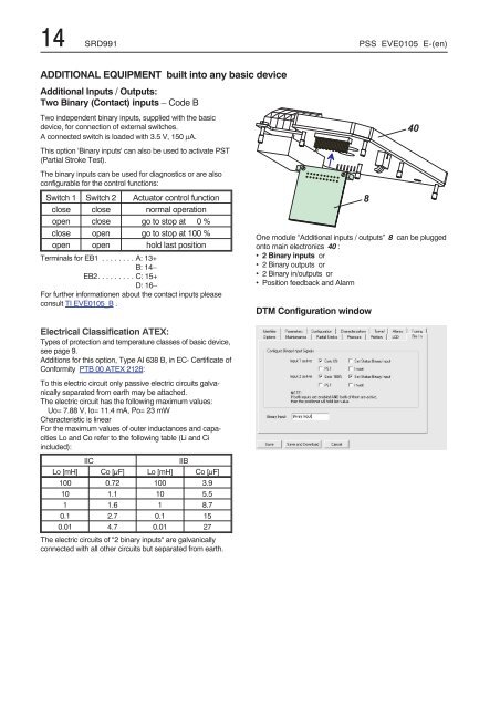
One module “Additional inputs / outputs” 8 can be plugged<br />
onto main electronics 40 :<br />
• 2 Binary inputs or<br />
• 2 Binary outputs or<br />
• 2 Binary in/outputs or<br />
• Position feedback and Alarm<br />
DTM Configuration window<br />
&<br />
"