Liquid level switch BM 34
Liquid level switch BM 34
Liquid level switch BM 34

Create successful ePaper yourself
Turn your PDF publications into a flip-book with our unique Google optimized e-Paper software.
© KROHNE 09/2001 7.02370.21.00<br />
GR/PRINTO<br />
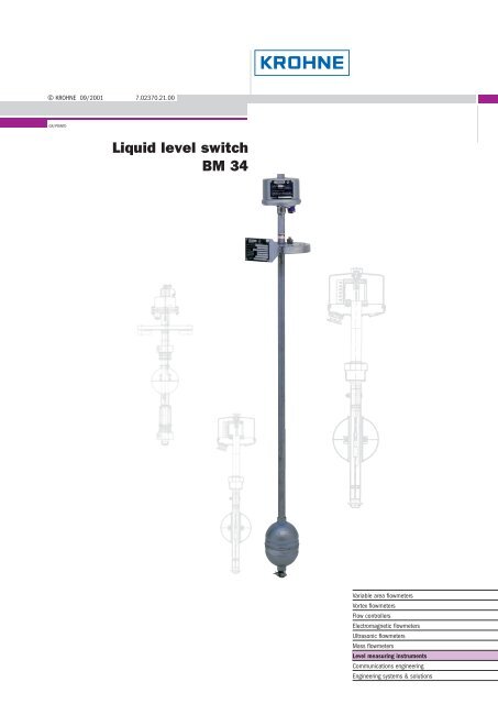
<strong>Liquid</strong> <strong>level</strong> <strong>switch</strong><br />
<strong>BM</strong> <strong>34</strong><br />
Status: 10/99<br />
Variable area flowmeters<br />
Vortex flowmeters<br />
Flow controllers<br />
Electromagnetic flowmeters<br />
Ultrasonic flowmeters<br />
Mass flowmeters<br />
Level measuring instruments<br />
Communications engineering<br />
Engineering systems & solutions
<strong>Liquid</strong> <strong>level</strong> <strong>switch</strong><br />
<strong>BM</strong> <strong>34</strong><br />
For use in potentially hazardous environments<br />
Operating principle<br />
A float guided on a non-magnetic tube<br />
follows the <strong>level</strong> of the liquid surface,thereby<br />
actuating up to 6 reed contacts, monostable<br />
or bistable, inside the tube via a built-in<br />
magnet system.<br />
Types of contacts<br />
All contacts are fitted to a rod with a clamping<br />
device. Where <strong>switch</strong>ing points are not<br />
known or the contact has to be adjustable<br />
the clamps are loosely attached.<br />
For overfill protection systems, the uppermost<br />
contact is non-detachable.<br />
The length of the guide tube and installation<br />
height of the reed contacts are specified<br />
from the lower edge of the screw connection<br />
or mounting flange.<br />
Approved for<br />
hazardous duty<br />
and as part of an<br />
overfill protection<br />
system<br />
Up to 6 freely<br />
adjustable or preset<br />
<strong>switch</strong>ing elements<br />
Temperature range<br />
–200 … +200°C<br />
(–328 … +392°F)<br />
and operating pressure<br />
max. 40 bar (580 psig)<br />
0.3 – 6 m<br />
(1 – 20 ft)<br />
tube length<br />
Monostable<br />
reed contacts<br />
These <strong>switch</strong>es are only<br />
actuated as long as the<br />
float and magnetic system<br />
are at an equal height.<br />
If the float moves away,<br />
the contact returns to its<br />
original setting.<br />
The achieved <strong>switch</strong>ing<br />
state can be maintained<br />
with an auxiliary relay.<br />
Floats with a ring magnet<br />
system are used.<br />
Bistable<br />
reed contacts<br />
These <strong>switch</strong>es are<br />
actuated by the float’s<br />
magnetic system and remain<br />
in the <strong>switch</strong>ing state.<br />
Therefore, they provide a<br />
clear indication of the float’s<br />
location, i.e. above or below<br />
the <strong>switch</strong>, without the need<br />
for an auxiliary relay. The<br />
<strong>switch</strong> setting is retained<br />
until the float moves past<br />
the <strong>switch</strong> in the opposite<br />
direction. Floats with a<br />
radial magnetic system are<br />
used.<br />
A variety of materials<br />
permits use also<br />
in aggressive media<br />
Float<br />
with ring<br />
magnet<br />
system<br />
Float<br />
with radial<br />
magnet<br />
system<br />
<strong>34</strong>
<strong>BM</strong> <strong>34</strong><br />
Range of application<br />
<strong>BM</strong> <strong>34</strong> is ideal wherever liquid <strong>level</strong>s need to be monitored in<br />
process and storage tanks.<br />
Typical liquids are:<br />
● Water and aqueous fluids<br />
● Acids / alkalis<br />
● Organic and inorganic solvents<br />
Special versions<br />
Interface detection, <strong>BM</strong> <strong>34</strong> TS<br />
If two liquids with different densities are stored in one tank, the <strong>level</strong><br />
of the interface can be measured using a special interface-type float.<br />
The weight and buoyancy of the float are such that it floats on the<br />
heavier and sinks in the lighter liquid. The minimum difference in density<br />
between both liquids should be greater than 100 g/l (6.24 lb/ft 3 ),<br />
and the float must be fully immersed in the light liquid.<br />
If the lighter liquid is not always stored in the tank, this must be<br />
specified on ordering to ensure appropriate float design.<br />
For ships’tank with test device, <strong>BM</strong> <strong>34</strong>/T<br />
In the <strong>BM</strong> <strong>34</strong>/T version, an additionally installed rod magnet in the<br />
tube can be raised with a test knob. By means of a magnetic coupling,<br />
a sleeve on the outside of the tube follows this motion. It is thus possible<br />
to raise the float to contact point, thus permitting a check of the<br />
instrument’s <strong>switch</strong>ing functions. If the float has developed a leak and<br />
filled with liquid, the magnetic coupling breaks off due to the heavier<br />
weight and no contact is produced.<br />
Guide tube centering aid<br />
For agitated liquids, a centering device welded to the tank bottom is<br />
recommended to avoid buckling of the guide tube.<br />
For approved devices, a bottom centering device is mandatory where<br />
the length of the guide tube is > 3000 mm (> 9.8 ft).<br />
Product<br />
Overview<br />
Vibration<br />
Continuous, non-contact Switches<br />
Ultrasonic Radar Ultrasonic Buoyancy Capacitance<br />
Materials /coatings<br />
For use in aggressive products, all wetted parts can be coated with PVC,<br />
PP or PTFE. Other materials are titanium or Hastelloy-C4.<br />
Continuous, contact<br />
Ultrasonic Buoyancy TDR<br />
Dimensions in mm (inches)<br />
<strong>BM</strong> <strong>34</strong><br />
35
<strong>BM</strong> <strong>34</strong><br />
Responsibility for suitability and intended use of our instruments rests solely with the purchaser.<br />
Technical data<br />
Length (guide tube)<br />
0.3 – 6 m (1 – 19.7 ft)<br />
Switching accuracy ± 3 mm (± 0.12’’)<br />
Max. allowable operating pressure<br />
Standard<br />
max. 40 bar (580 psig)<br />
<strong>BM</strong> <strong>34</strong>/F/WB, <strong>BM</strong> <strong>34</strong>/F/WN max. 3 bar (43.5 psig)<br />
<strong>BM</strong> <strong>34</strong>/Ex/Z0, <strong>BM</strong> <strong>34</strong>/F/Ex/Z0<br />
max. 35 bar (508 psig)<br />
depending on flange pressure rating and float pressure resistance.<br />
Process temperature<br />
Standard<br />
–55 … +150°C ( –67 … +302°F)<br />
Option<br />
–200 … +200°C (–328 … +392°F)<br />
<strong>BM</strong> <strong>34</strong>/Ex/Z0<br />
–20 … +150°C ( –4 … +302°F)<br />
<strong>BM</strong> <strong>34</strong>/F/WB<br />
–20 … +60°C ( –4 … +140°F)<br />
<strong>BM</strong> <strong>34</strong>/F/WN<br />
–20 … +200°C ( –4 … +392°F)<br />
<strong>BM</strong> <strong>34</strong>/F/Ex/Z0<br />
–20 … +75°C ( –4 … +167°F)<br />
Operating data<br />
Min. density<br />
Standard, <strong>BM</strong> <strong>34</strong>/Ex/Z0 0.4 kg/l (25 lb/ft 3 )<br />
Option, <strong>BM</strong> <strong>34</strong>/F/WB, <strong>BM</strong> <strong>34</strong>/F/WN, <strong>BM</strong> <strong>34</strong>/F/Ex/Z0 0.5 kg/l (31 lb/ft 3 )<br />
Viscosity*<br />
Standard<br />
≤ 5000 m Pa·s<br />
For approved instruments<br />
≤ 1000 m Pa·s<br />
Solids content*<br />
≤ 100 g/l (6.24 lb/ft 3 ) =^ 10% dry substance<br />
Particle size* ≤ 200 µm<br />
Reed contacts<br />
Type/number<br />
max. 6 monostable or 6 bistable changeover contacts<br />
(bistable contact not possible with F/WN, F/WB or F/Ex/Z0)<br />
Version Standard F/WN, F/WB Ex/Z0, F/Ex/Z0<br />
Operating voltage 65 V 30 V 20 V<br />
Max. contact rating 40 W / 60 VA 0.9 W (VA) 200 mW (VA)<br />
Max. current <strong>switch</strong>ed 1 A 30 mA 40 mA<br />
Contact spacing<br />
monostable changeover contact > 50 mm (1.97’’)<br />
bistable changeover contact > 70 mm (2.76’’)<br />
Switching hysteresis 5 mm (0.2’’)<br />
Holding range 17 mm (0.67’’)<br />
Lowermost <strong>switch</strong>ing point < guide tube length – 130 mm (5.12’’)<br />
Uppermost <strong>switch</strong>ing point<br />
> 100 mm (3.94’’) distance from bottom edge of flange<br />
Connection<br />
Standard DIN 2501, Form C DN 25, PN 40<br />
Option DIN 2501, Form C DN 40 – DN 150/PN 6 – PN 40<br />
ANSI B 16.5 1’’– 6’’ 150/300 lb/RF<br />
DIN 2999<br />
G 11/2’’ A (SW 50 mm wrench)<br />
Plastic-coated flanges DIN 2501, Form C ≥ DN 50/PN 6 – PN 40<br />
ANSI B 16.5 ≥ 2’’ 150/300 lb/RF<br />
<strong>BM</strong> <strong>34</strong>/T DIN 2501, Form C DN 50/PN 40<br />
ANSI B 16.5 2’’ 150/300 lb/RF<br />
Information on higher pressure ratings and other standards available on request<br />
Protection category to EN 60529 / IEC 529 IP 56, equivalent to NEMA 3<br />
Materials<br />
Flanges<br />
Screw connection<br />
Guide tube<br />
Float<br />
Housing<br />
Stainless steel 1.4571 (316 Ti)<br />
Stainless steel 1.4571 (316 Ti)/titanium plated<br />
Stainless steel 1.4571 coated with PVC, PP or PTFE<br />
Stainless steel 1.4571 (316 Ti)<br />
See instrument versions<br />
See Selection of float type<br />
Stainless steel 1.4571 (316 Ti)<br />
* Relevant for instruments approved as part of an overfill protection system.<br />
36<br />
<strong>BM</strong> <strong>34</strong>
<strong>BM</strong> <strong>34</strong><br />
Selection of float type<br />
Shape Dimensions Materials Min. density Max. allowable Product temperature<br />
(diameter x height x wall-thickness) operating pressure min. max.<br />
in mm in inches kg/l lb/ft 3 bar psig °C °F °C °F<br />
Standard versions without explosion protection<br />
Cylinder 97 x 145 x 1.0 3.82 x 5.71 x 0.04 Stainless steel 1.4571 (316 Ti) 0.85 53.07 40 580 -200 -328 200 392<br />
Cylinder 97 x 145 x 0.6 3.82 x 5.71 x 0.02 Stainless steel 1.4571 (316 Ti) 0.70 43.70 25 363 -200 -328 200 392<br />
Ball 142 x 145 x 0.7 5.59 x 5.71 x 0.03 Stainless steel 1.4571 (316 Ti) 0.40 24.97 25 363 -200 -328 200 392<br />
Ball 142 x 145 x 1.0 5.59 x 5.71 x 0.04 Stainless steel 1.4571 (316 Ti) 0.50 31.21 40 580 -200 -328 200 392<br />
Cylinder 97 x 145 x 1.0 3.82 x 5.71 x 0.04 Titanium 0.45 28.09 35 508 -160 -256 200 392<br />
Ball 142 x 145 x 1.0 5.59 x 5.71 x 0.04 Titanium 0.40 24.97 35 508 -160 -256 200 392<br />
Cylinder 94 x 100 3.70 x 3.94 PVC 0.60 37.46 4 58 -40 -40 40 104<br />
Cylinder 94 x 100 3.70 x 3.94 PP 0.40 24.97 4 58 10 50 60 140<br />
Cylinder 130 x 165 5.12 x 6.50 Hard glass 0.70 43.70 16 232 -50 -58 200 392<br />
Cylinder 94 x 100 3.70 x 3.94 PVDF 0.70 43.70 4 58 -40 -40 100 212<br />
Cylinder 140 x 175 x 1.0 5.51 x 6.89 x 0.04 Hastelloy-C4 0.70 43.70 2 29 -200 -328 200 392<br />
<strong>BM</strong> <strong>34</strong>/T<br />
Ball 142 x 145 x 1.0 5.59 x 5.71 x 0.04 Titanium 0.40 24.97 35 508 -160 -256 200 392<br />
Instrument approved for use in Zone 0 (EC)<br />
<strong>BM</strong> <strong>34</strong>/Ex/Z0<br />
Cylinder 97 x 145 x 1.0 3.82 x 5.71 x 0.04 Stainless steel 1.4571 (316 Ti) 0.85 53.07 35 508 -20 -4 150 302<br />
Cylinder 97 x 145 x 0.6 3.82 x 5.71 x 0.02 Stainless steel 1.4571 (316 Ti) 0.70 43.70 22 319 -20 -4 150 302<br />
Ball 142 x 145 x 0.7 5.59 x 5.71 x 0.03 Stainless steel 1.4571 (316 Ti) 0.40 24.97 22 319 -20 -4 150 302<br />
Ball 142 x 145 x 1.0 5.59 x 5.71 x 0.04 Stainless steel 1.4571 (316 Ti) 0.50 31.21 35 508 -20 -4 150 302<br />
Ball 97 x 145 x 1.0 3.82 x 5.71 x 0.04 Titanium 0.45 28.09 30 435 -20 -4 150 302<br />
Ball 142 x 145 x 1.0 5.59 x 5.71 x 0.04 Titanium 0.40 24.97 30 435 -20 -4 150 302<br />
Instruments approved as part of an overfill protection system<br />
<strong>BM</strong> <strong>34</strong>/F/Ex/Z0<br />
Cylinder 97 x 145 x 1.0 3.82 x 5.71 x 0.04 Stainless steel 1.4571 (316 Ti) 1.00 62.43 28 406 -20 -4 75 167<br />
Ball 142 x 145 x 1.0 5.59 x 5.71 x 0.04 Stainless steel 1.4571 (316 Ti) 0.65 40.58 28 406 -20 -4 75 167<br />
Cylinder 97 x 145 x 1.0 3.82 x 5.71 x 0.04 Titanium 0.60 37.46 23 3<strong>34</strong> -20 -4 75 167<br />
Ball 142 x 145 x 1.0 5.59 x 5.71 x 0.04 Titanium 0.50 31.21 23 3<strong>34</strong> -20 -4 75 167<br />
<strong>BM</strong> <strong>34</strong>/F/WB<br />
Cylinder 97 x 145 x 1.0 3.82 x 5.71 x 0.04 Stainless steel 1.4571 (316 Ti) 1.00 62.43 3 44 -20 -4 60 140<br />
Ball 142 x 145 x 1.0 5.59 x 5.71 x 0.04 Stainless steel 1.4571 (316 Ti) 0.65 40.58 3 44 -20 -4 60 140<br />
Cylinder 97 x 145 x 1.0 3.82 x 5.71 x 0.04 Titanium 0.60 37.46 3 44 -20 -4 60 140<br />
Ball 142 x 145 x 1.0 5.59 x 5.71 x 0.04 Titanium 0.50 31.21 3 44 -20 -4 60 140<br />
<strong>BM</strong> <strong>34</strong>/F/WN<br />
Cylinder 97 x 145 x 1.0 3.82 x 5.71 x 0.04 Stainless steel 1.4571 (316 Ti) 1.00 62.43 3 29 -20 -4 200 392<br />
Ball 142 x 145 x 1.0 5.59 x 5.71 x 0.04 Stainless steel 1.4571 (316 Ti) 0.65 40.58 3 44 -20 -4 200 392<br />
Cylinder 140 x 170 x 1.0 5.51 x 6.69 x 0.04 Hastelloy-C4 0.70 43.70 2 29 -20 -4 200 392<br />
Cylinder 97 x 145 x 1.0 3.82 x 5.71 x 0.04 Titanium 0.60 37.46 3 29 -20 -4 200 392<br />
Ball 142 x 145 x 1.0 5.59 x 5.71 x 0.04 Titanium 0.50 31.21 3 44 -20 -4 200 392<br />
Product<br />
Overview<br />
Vibration<br />
Continuous, non-contact Switches<br />
Ultrasonic Radar Ultrasonic Buoyancy Capacitance<br />
Continuous, contact<br />
Ultrasonic Buoyancy TDR<br />
Important !<br />
The specified max. allowable operating pressure applies to 20°C or 68°F only!<br />
Float test pressure = 1.3 times the max. allowable operating pressure.<br />
Hazardous-duty units = 1.5 times the max. allowable operating pressure.<br />
<strong>BM</strong> <strong>34</strong><br />
37
<strong>BM</strong> <strong>34</strong><br />
Instrument versions<br />
Version <strong>BM</strong> <strong>34</strong>/RR <strong>BM</strong> <strong>34</strong>/R* <strong>BM</strong> <strong>34</strong>/R-PVC <strong>BM</strong> 24 R-PP<br />
(not approved)<br />
(not approved)<br />
Flange Stainless steel 1.4571 Screw connection Stainless steel 1.4571 Stainless steel 1.4571<br />
(316 Ti) Stainless steel 1.4571 (316 Ti) (316 Ti)<br />
(316 Ti) with PVC face with PP face<br />
Guide tube Stainless steel 1.4571 Stainless steel 1.4571 Stainless steel 1.4571 Stainless steel 1.4571<br />
material (316 Ti) (316 Ti) (316 Ti) / with PVC tube (316 Ti) / with PP tube<br />
Guide tube<br />
dimensions<br />
mm 21.30 x 2.00 21.30 x 2.00 20.00 x 1.50 / 25.00 x 1.80 20.00 x 1.50 / 25.00 x 1,80<br />
inches 0.84 x 0.08 0.84 x 0.08 0.79 x 0.06 / 0.98 x 0.07 0.79 x 0.06 / 0.98 x 0.07<br />
Weight **<br />
approx. kg 4 3 5 5<br />
approx. lb 8.8 6.6 11 11<br />
Version <strong>BM</strong> <strong>34</strong>/R-PTFE <strong>BM</strong> <strong>34</strong>/R-Titan <strong>BM</strong> <strong>34</strong>/R-Hastelloy-C4<br />
(not approved)<br />
Flange Stainless steel 1.4571 Stainless steel 1.4571 Stainless steel 1.4571<br />
(316 Ti) (316 Ti) (316 Ti)<br />
with PTFE face titanium plated Hastelloy-C4 plated<br />
Guide tube<br />
material Stainless steel 1.4571 Titanium Hastelloy-C4<br />
(316 Ti) / with PTFE tube<br />
Guide tube<br />
dimensions<br />
mm 21.30 x 2.00 /25.00 x 2.00 21.30 x 2.00 25.00 x 1.60<br />
inches 0.84 x 0.08 / 0.98 x 0.08 0.84 x 0.08 0.98 x 0.06<br />
Weight **<br />
approx. kg 5 4.5 4.5<br />
approx. lb 11 9.9 9.9<br />
** Only for standard instruments and those approved for use in Zone 0<br />
** Weight = Instrument with 1 m (3.3 ft) guide tube length plus 1 kg (2.2 lb) for every additional meter (3.3 ft) tube length<br />
Guide tube test pressure = 1.5 times the max. allowable operating pressure at 20°C (68°F).<br />
38<br />
<strong>BM</strong> <strong>34</strong>
<strong>BM</strong> <strong>34</strong><br />
Dimensions<br />
in mm (inches)<br />
<strong>BM</strong> <strong>34</strong>/RR<br />
Flange version<br />
<strong>BM</strong> <strong>34</strong>/R<br />
Version with screw connection<br />
<strong>BM</strong> <strong>34</strong>/T<br />
For ships’ tank with test device<br />
Product<br />
Overview<br />
1 Cap<br />
2 Test knob<br />
3 Wire<br />
4 Reed contact<br />
5 Float<br />
6 Rod magnet<br />
7 Sleeve<br />
Vibration<br />
Continuous, non-contact Switches<br />
Ultrasonic Radar Ultrasonic Buoyancy Capacitance<br />
Continuous, contact<br />
Ultrasonic Buoyancy TDR<br />
<strong>BM</strong> <strong>34</strong><br />
39
<strong>BM</strong> <strong>34</strong><br />
Approvals<br />
Application Instrument version Certification mark<br />
With explosion protection <strong>BM</strong> <strong>34</strong> /– / K .. / Ex / Z0 PTB No. Ex-85 / 2156 X<br />
In stationary storage tanks for flammable<br />
water pollutants in classes AI, AII and B (excl. CS 2 ),<br />
float and guide tube in Zone 0<br />
Overfill protection with explosion protection <strong>BM</strong> <strong>34</strong> /– / K ..- F / Ex / Z0 PTB No. III B / E 26390 F<br />
In stationary storage tanks for flammable,<br />
water pollutants in classes AI, AII and B (excl. CS 2 ),<br />
float and guide tube in Zone 0<br />
Overfill protection without explosion protection <strong>BM</strong> <strong>34</strong> /– / K ..- F / WB PTB No. III B / S 1806 F<br />
In stationary tanks [max. operating pressure<br />
3 bar (43.5 psig)] for flammable water pollutants<br />
in class AIII<br />
Overfill protection without explosion protection <strong>BM</strong> <strong>34</strong> /– / K ..- F / WN DIBT Approval Notice Z-65.11-223<br />
In stationary tanks [max. operating pressure<br />
3 bar (43.5 psig)] for non-flammable water pollutants<br />
PTB = Physikalisch-Technische Bundesanstalt<br />
Type code<br />
Instrument<br />
<strong>BM</strong> <strong>34</strong> <strong>Liquid</strong> <strong>level</strong> <strong>switch</strong><br />
Material<br />
RR<br />
Stainless steel<br />
R<br />
Stainless steel, screw connection<br />
R-PVC PVC version<br />
R-PP PP version<br />
R-PTFE PTFE version<br />
R-Titan Titanium version<br />
R-Hastelloy-C4 Hastelloy-C4 version<br />
Number of contacts<br />
K1 1 contact K4 4 contacts<br />
K2 2 contacts K5 5 conatcts<br />
K3 3 contacts K6 6 contacts<br />
Type of contact<br />
W monostable<br />
Bi bistable (not approved as part of an overfill protection system)<br />
Range of application<br />
N normal range (not for approved instruments)<br />
Ex/Z0 electrical equipment for use in hazardous areas<br />
F/Ex/Z0 hazardous-area electrical equipment as part of an<br />
overfill protection system for flammable<br />
water pollutants, classes AI, AII, B<br />
F/WB part of an overfill protection system for flammable,<br />
water pollutants, class AIII<br />
F/WN part of an overfill protection system for non-flammable,<br />
water pollutants<br />
Special versions<br />
T Instrument with test device for non-hazardous areas<br />
and for ships’ tanks<br />
TS Interface detection (when used in Zone 0, the<br />
max. guide tube length is dependent on the float weight).<br />
Not approved as part of an overfill protection system.<br />
<strong>BM</strong> <strong>34</strong><br />
40<br />
<strong>BM</strong> <strong>34</strong>