Draft LCP OU-2 Remedial Design Report - New York State ...
Draft LCP OU-2 Remedial Design Report - New York State ...
Draft LCP OU-2 Remedial Design Report - New York State ...

You also want an ePaper? Increase the reach of your titles
YUMPU automatically turns print PDFs into web optimized ePapers that Google loves.
PARSONS<br />
DRAFT <strong>LCP</strong> <strong>OU</strong>-2<br />
REMEDIAL DESIGN REPORT<br />
Prepared For:<br />
301 Plainfield Road, Suite 330<br />
Syracuse, <strong>New</strong> <strong>York</strong> 13212<br />
Prepared By:<br />
Parsons<br />
301 Plainfield Road, Suite 350<br />
Syracuse, <strong>New</strong> <strong>York</strong> 13212<br />
Phone: (315) 451-9560<br />
Fax: (315) 451-9570<br />
In Association with:<br />
Environmental Remediation & Financial Services, LLC<br />
OCTOBER 2012
TABLE OF CONTENTS<br />
DRAFT <strong>LCP</strong> <strong>OU</strong>-2<br />
REMEDIAL DESIGN REPORT<br />
EXECUTIVE SUMMARY ........................................................................................ ES-1<br />
SECTION 1 INTRODUCTION................................................................................... 1-1<br />
1.1 PURPOSE .......................................................................................................... 1-1<br />
1.2 SITE DESCRIPTION AND BACKGR<strong>OU</strong>ND ................................................. 1-1<br />
1.3 REMEDIAL OBJECTIVES .............................................................................. 1-2<br />
1.4 SELECTED RESPONSE ACTION .................................................................. 1-2<br />
SECTION 2 PRE-DESIGN INVESTIGATIONS ...................................................... 2-1<br />
2.1 PILOT TESTING .............................................................................................. 2-1<br />
2.2 2012 SHALLOW SOIL INVESTIGATION ..................................................... 2-1<br />
2.3 2012 DEEP SOIL CHARACTERIZATION ..................................................... 2-2<br />
2.4 2012 BASELINE GR<strong>OU</strong>NDWATER QUALITY ............................................ 2-2<br />
SECTION 3 DESIGN ELEMENTS ............................................................................ 3-1<br />
3.1 GENERAL SITE WORK .................................................................................. 3-1<br />
3.1.1 On-site Utilities ....................................................................................... 3-1<br />
3.1.2 Site Preparation and Control ................................................................... 3-1<br />
3.2 SHALLOW SOILS ............................................................................................ 3-2<br />
3.2.1 Stormwater Management/ Erosion Control ............................................. 3-2<br />
3.2.2 Gravel Removal/ Staging/ Reuse ............................................................. 3-2<br />
3.2.3 Soil Excavation ........................................................................................ 3-2<br />
3.2.4 Transportation and Disposal .................................................................... 3-3<br />
3.2.5 Confirmatory Sampling ........................................................................... 3-3<br />
3.2.6 Backfill/ Final Grade ............................................................................... 3-4<br />
3.2.7 Odor Control ............................................................................................ 3-4<br />
3.3 DEEP SOIL/ GR<strong>OU</strong>NDWATER ...................................................................... 3-4<br />
3.3.1 In-Situ Chemical Oxidation ..................................................................... 3-4<br />
Page<br />
PARSONS<br />
P:\Honeywell -SYR\446893 - <strong>LCP</strong> <strong>OU</strong>-2 <strong>Remedial</strong> <strong>Design</strong>\9.0 <strong>Report</strong>s\9.1 <strong>LCP</strong> <strong>OU</strong>-2 <strong>Remedial</strong> <strong>Design</strong> <strong>Report</strong>\<strong>LCP</strong> <strong>OU</strong>-2 <strong>Design</strong> <strong>Report</strong><br />
Rev5.docx<br />
i
TABLE OF CONTENTS (CONTINUED)<br />
DRAFT <strong>LCP</strong> <strong>OU</strong>-2<br />
REMEDIAL DESIGN REPORT<br />
3.3.2 Summary of ERFS SOW ......................................................................... 3-5<br />
3.3.3 Remedy Performance Monitoring (Soil and Groundwater) .................... 3-5<br />
3.3.3.1 Additional Pre-ISCO Monitoring ............................................. 3-5<br />
3.3.3.1.1 Baseline Groundwater Monitoring .......................... 3-5<br />
3.3.3.1.2 Soil Monitoring ....................................................... 3-6<br />
3.3.3.2 Interim Progress Monitoring .................................................... 3-6<br />
3.3.3.3 Pre-Final Sampling ................................................................... 3-6<br />
3.3.3.3.1 Groundwater ............................................................ 3-6<br />
3.3.3.3.2 Soils ......................................................................... 3-7<br />
3.3.4 West Flume / Aquifer / Barrier Wall Monitoring .................................... 3-7<br />
3.3.5 Evaluation of Final Sampling Results ..................................................... 3-7<br />
3.4 ENVIRONMENTAL EASEMENT .................................................................. 3-7<br />
3.5 SITE MANAGEMENT PLAN .......................................................................... 3-8<br />
3.5.1 Management of Final Cover .................................................................... 3-8<br />
3.5.2 Site Access Control ................................................................................. 3-8<br />
3.5.3 Groundwater Monitoring ......................................................................... 3-8<br />
3.5.4 Redevelopment Monitoring ..................................................................... 3-8<br />
SECTION 4 SCHEDULE............................................................................................. 4-1<br />
SECTION 5 REFERENCES ........................................................................................ 5-1<br />
Page<br />
PARSONS<br />
P:\Honeywell -SYR\446893 - <strong>LCP</strong> <strong>OU</strong>-2 <strong>Remedial</strong> <strong>Design</strong>\9.0 <strong>Report</strong>s\9.1 <strong>LCP</strong> <strong>OU</strong>-2 <strong>Remedial</strong> <strong>Design</strong> <strong>Report</strong>\<strong>LCP</strong> <strong>OU</strong>-2 <strong>Design</strong> <strong>Report</strong><br />
Rev5.docx<br />
ii
TABLE OF CONTENTS (CONTINUED)<br />
FIGURES<br />
Figure 1.1 Site Map<br />
Figure 1.2 <strong>Remedial</strong> <strong>Design</strong> Summary<br />
Figure 2.1 <strong>LCP</strong> <strong>OU</strong>-2 Shallow Soil Sample Locations and Results (Pre 2012)<br />
Figure 2.2 <strong>LCP</strong> <strong>OU</strong>-2 Shallow Soil Sample Locations and Results (2012)<br />
Figure 2.3 <strong>LCP</strong> <strong>OU</strong>-2 Total VOCs in Subsurface Soils<br />
Figure 2.4 <strong>LCP</strong> <strong>OU</strong>-2 Groundwater Sample Locations and Results (Pre 2012)<br />
Figure 3.1 ISCO Typical Site Layout<br />
APPENDICES<br />
DRAFT <strong>LCP</strong> <strong>OU</strong>-2<br />
REMEDIAL DESIGN REPORT<br />
APPENDIX A ISCO WORK PLAN<br />
APPENDIX B DESIGN DRAWINGS<br />
APPENDIX C CONSTRUCTION QUALITY ASSURANCE PLAN (CQAP)<br />
APPENDIX D COMMUNITY AIR MONITORING PLAN (CAMP)<br />
PARSONS<br />
P:\Honeywell -SYR\446893 - <strong>LCP</strong> <strong>OU</strong>-2 <strong>Remedial</strong> <strong>Design</strong>\9.0 <strong>Report</strong>s\9.1 <strong>LCP</strong> <strong>OU</strong>-2 <strong>Remedial</strong> <strong>Design</strong> <strong>Report</strong>\<strong>LCP</strong> <strong>OU</strong>-2 <strong>Design</strong> <strong>Report</strong><br />
Rev5.docx<br />
iii
gs Below ground surface<br />
ACRONYMS<br />
CAMP Community Air Monitoring Plan<br />
CPOI Chemical parameter of interest<br />
CQAP Construction Quality Assurance Plan<br />
cy Cubic yards<br />
ERFS Environmental Remediation & Financial Services, LLC<br />
FS Feasibility study<br />
DRAFT <strong>LCP</strong> <strong>OU</strong>-2<br />
REMEDIAL DESIGN REPORT<br />
ft Foot<br />
GPR Ground penetrating radar<br />
INSOTEC In situ Oxidative Technologies, Inc.<br />
ISCO In situ chemical oxidation<br />
<strong>LCP</strong> <strong>OU</strong>-2 Linden Chemical and Plastics Operating Unit 2<br />
LNAPL Light non-aqueous phase liquid<br />
µg/kg Micrograms per kilogram<br />
µg/L Micrograms per liter<br />
ND Non-detect<br />
NYSDEC <strong>New</strong> <strong>York</strong> <strong>State</strong> Department of Environmental Conservation<br />
NYSDOH <strong>New</strong> <strong>York</strong> <strong>State</strong> Department of Health<br />
PVC Polyvinyl chloride<br />
RDWP <strong>Remedial</strong> <strong>Design</strong> Work Plan<br />
RI <strong>Remedial</strong> Investigation<br />
ROD Record of Decision<br />
SCO NYSDEC Soil Cleanup Objectives<br />
SMP Site Management Plan<br />
SVOC Semi-volatile organic compound<br />
USEPA US Environmental Protection Agency<br />
VOC Volatile organic compound<br />
PARSONS<br />
P:\Honeywell -SYR\446893 - <strong>LCP</strong> <strong>OU</strong>-2 <strong>Remedial</strong> <strong>Design</strong>\9.0 <strong>Report</strong>s\9.1 <strong>LCP</strong> <strong>OU</strong>-2 <strong>Remedial</strong> <strong>Design</strong> <strong>Report</strong>\<strong>LCP</strong> <strong>OU</strong>-2 <strong>Design</strong> <strong>Report</strong><br />
Rev5.docx<br />
iv
EXECUTIVE SUMMARY<br />
DRAFT <strong>LCP</strong> <strong>OU</strong>-2<br />
REMEDIAL DESIGN REPORT<br />
The remediation of Linden Chemical and Plastics Operable Unit 2 (<strong>LCP</strong> <strong>OU</strong>-2) is part of the<br />
continuing effort to restore the overall former <strong>LCP</strong> site, which is located in an industrial area on<br />
Gerelock Road in the Town of Geddes, The 20-acre site consists of two <strong>OU</strong>s. The <strong>LCP</strong> <strong>OU</strong>-2<br />
site, the subject of this design, was formerly a hydrogen peroxide plant.<br />
A Record of Decision (ROD) outlining the selected remedy for <strong>LCP</strong> <strong>OU</strong>-2 was issued in<br />
April 2010. The ROD included several remedial activities to address contamination in the <strong>LCP</strong><br />
<strong>OU</strong>-2 soils and groundwater. This report describes design elements that are necessary for the<br />
implementation of the remedy, including the following:<br />
� In situ chemical oxidation to permanently treat site soil and groundwater chemical<br />
parameters of interest at multiple depths to meet target <strong>New</strong> <strong>York</strong> <strong>State</strong> Department of<br />
Environmental Conservation (NYSDEC) Part 375 standards<br />
� Excavation and offsite disposal of approximately 3,100 cubic yards (cy) of shallow soils<br />
from around the former building footprints<br />
� Installation of 1 ft. of clean gravel cap and demarcation layer following remediation<br />
The ROD also included the development of a site management plan (SMP) and an<br />
environmental easement for the property, including provisions for managing the redevelopment<br />
and reuse of the site to be consistent with the established remedial goals. The SMP and<br />
environmental easement will be finalized following completion of the remedial activities<br />
described herein.<br />
Honeywell has conducted activities that support the design of the selected remedy and<br />
support and supplement data collected during the <strong>Remedial</strong> Investigation (Parsons 2004). These<br />
pre-design activities included bench-scale and full-scale pilot studies, additional soil and<br />
groundwater sampling, and removal of shallow soils as part of the remedy for the <strong>LCP</strong> <strong>OU</strong>-1<br />
site.<br />
This design report has been developed in consideration of the NYSDEC Green Remediation<br />
and the US Environmental Protection Agency (USEPA) Region 2 Clean and Green policies.<br />
PARSONS<br />
P:\Honeywell -SYR\446893 - <strong>LCP</strong> <strong>OU</strong>-2 <strong>Remedial</strong> <strong>Design</strong>\9.0 <strong>Report</strong>s\9.1 <strong>LCP</strong> <strong>OU</strong>-2 <strong>Remedial</strong> <strong>Design</strong> <strong>Report</strong>\<strong>LCP</strong> <strong>OU</strong>-2 <strong>Design</strong> <strong>Report</strong><br />
Rev5.docx<br />
October 17, 2012<br />
ES-1
1.1 PURPOSE<br />
SECTION 1<br />
INTRODUCTION<br />
DRAFT <strong>LCP</strong> <strong>OU</strong>-2<br />
REMEDIAL DESIGN REPORT<br />
This report presents the design for the <strong>LCP</strong> <strong>OU</strong>-2 <strong>Remedial</strong> Action. It continues the work<br />
being performed under the <strong>LCP</strong> <strong>OU</strong>-2 ROD (ROD; Index #D7-0001-01-03) (NYSDEC, 2010)<br />
and builds on the following previous submittals:<br />
� <strong>Remedial</strong> Investigation (RI) (Parsons, 2004)<br />
� Feasibility Study (FS) (Parsons, 2009)<br />
� <strong>Remedial</strong> <strong>Design</strong> Work Plan (RDWP) (Parsons, 2011b)<br />
This report includes plans and specifications for:<br />
� Removing approximately 3,100 cy of soil from the unsaturated shallow zone and<br />
backfilling the removal area<br />
� Implementing ISCO technology to remediate saturated soils and groundwater in place<br />
� Installing additional monitoring wells and erosion controls during construction<br />
� Restoring surfaces and constructing a final cover<br />
� Providing a description of the content of a SMP<br />
1.2 SITE DESCRIPTION AND BACKGR<strong>OU</strong>ND<br />
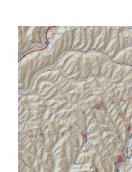
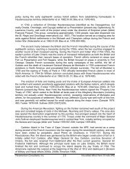
The former <strong>LCP</strong> site is located 2 miles northwest of the City of Syracuse, in the Town of<br />
Geddes, Onondaga County, <strong>New</strong> <strong>York</strong> (see Figure 1.1). The approximately 20-acre site is<br />
located in an industrial area on Gerelock Road (formerly called Belle Isle Road), west of Bridge<br />
Street (Route 297), and south of the <strong>New</strong> <strong>York</strong> <strong>State</strong> Fairgrounds and an active railroad right-ofway.<br />
The former <strong>LCP</strong> site consists of two <strong>OU</strong>s. The <strong>OU</strong>-2 site, the subject of this design, is a 1.7acre<br />
area in the eastern portion of the site where a former hydrogen peroxide plant was located.<br />
<strong>LCP</strong> <strong>OU</strong>-2 is located north of the West Flume, south of the <strong>New</strong> <strong>York</strong> <strong>State</strong> Fairgrounds, east of<br />
an area of <strong>OU</strong>-1 called the brine mud area, and west of the former NAKOH Chemical facility.<br />
The manufactured hydrogen peroxide at <strong>LCP</strong> <strong>OU</strong>-2 used hydrogen gas generated as a byproduct<br />
of the chlor-alkali facility located on <strong>OU</strong>-1. This process included the use of xylene to<br />
manufacture hydrogen peroxide. The contaminated soil and groundwater at <strong>OU</strong>-2 resulted from<br />
spills and/or leaks of production chemicals that occurred while the hydrogen peroxide facility<br />
was in operation.<br />
The other operable unit for the <strong>LCP</strong> site is <strong>OU</strong>-1. NYSDEC issued a ROD for <strong>OU</strong>-1 in 2000.<br />
All of the remedial work at <strong>OU</strong>-1 was completed by 2008, with the exception of the final cap<br />
that will be placed once remediation of Ninemile Creek is complete. Remediation of <strong>OU</strong>-1<br />
included some work on <strong>OU</strong>-2. The two buildings formerly located on <strong>OU</strong>-2, a hydrogen<br />
PARSONS<br />
P:\Honeywell -SYR\446893 - <strong>LCP</strong> <strong>OU</strong>-2 <strong>Remedial</strong> <strong>Design</strong>\9.0 <strong>Report</strong>s\9.1 <strong>LCP</strong> <strong>OU</strong>-2 <strong>Remedial</strong> <strong>Design</strong> <strong>Report</strong>\<strong>LCP</strong> <strong>OU</strong>-2 <strong>Design</strong> <strong>Report</strong><br />
Rev5.docx<br />
October 17, 2012<br />
1-1
DRAFT <strong>LCP</strong> <strong>OU</strong>-2<br />
REMEDIAL DESIGN REPORT<br />
peroxide plant process building and a hydrogen compressor building, and associated tanks and<br />
containers were demolished and/or removed in 2001. In addition, the <strong>OU</strong>-2 underground sewers<br />
and utilities were removed, and surface soil was excavated to depths between 1 and 3 ft. as part<br />
of the <strong>OU</strong>-1 remedial action. Following excavation and regrading, the <strong>OU</strong>-2 site was covered<br />
with approximately 6 inches of clean gravel in August 2005.<br />
1.3 REMEDIAL OBJECTIVES<br />
The <strong>LCP</strong> <strong>OU</strong>-2 remedial objectives, as presented in the ROD (NYSDEC 2010), are to<br />
eliminate or reduce to the extent practicable:<br />
� Exposures of persons at or around the site to volatile organic compounds (VOCs),<br />
semi-volatile organic compounds (SVOCs), and metals in soil<br />
� Exposures of persons at or around the site to VOCs, SVOCs, and metals in<br />
groundwater<br />
� Environmental exposures of flora or fauna to VOCs, SVOCs, and metals in soil<br />
� Contaminant releases from soil into groundwater that may create exceedances of<br />
groundwater quality standards<br />
Further, the remediation goals for the site include attaining to the extent practicable:<br />
� Ambient groundwater quality objectives meeting 6 NYCRR Part 703-3 Surface Water<br />
and Groundwater Quality Standards and Groundwater Effluent Limitations<br />
(http://www.dec.ny.gov/regs/4590.html)<br />
� Soil quality objectives meeting 6 NYCRR Part 375-6 <strong>Remedial</strong> Program Soil Cleanup<br />
Objectives (SCOs) (http://www.dec.ny.gov/regs/15507.html)<br />
Remediation objectives for ethylbenzene and xylene, the primary contaminants found at the<br />
<strong>OU</strong>-2 site, are summarized below:<br />
Chemical<br />
Compound<br />
Groundwater Cleanup<br />
Objective<br />
(Class GA)<br />
SCO (Part 375 Protection of<br />
Groundwater)<br />
Ethylbenzene 5 µg/L 1,000 µg/kg<br />
Xylene 5 µg/L 1,600 µg/kg<br />
µg/L – micrograms per liter<br />
µg/kg – micrograms per kilogram<br />
1.4 SELECTED RESPONSE ACTION<br />
The following selected response actions for <strong>OU</strong>-2 are presented in the ROD (NYSDEC<br />
2010):<br />
1. A remedial design program would be implemented to provide the details necessary for<br />
the construction, operation, maintenance, and monitoring of the remedial program.<br />
PARSONS<br />
P:\Honeywell -SYR\446893 - <strong>LCP</strong> <strong>OU</strong>-2 <strong>Remedial</strong> <strong>Design</strong>\9.0 <strong>Report</strong>s\9.1 <strong>LCP</strong> <strong>OU</strong>-2 <strong>Remedial</strong> <strong>Design</strong> <strong>Report</strong>\<strong>LCP</strong> <strong>OU</strong>-2 <strong>Design</strong> <strong>Report</strong><br />
Rev5.docx<br />
October 17, 2012<br />
1-2
DRAFT <strong>LCP</strong> <strong>OU</strong>-2<br />
REMEDIAL DESIGN REPORT<br />
2. Chemical oxidant(s) and catalyst(s) would be injected into the subsurface to address<br />
site remedial action objectives. In addition to the injection of chemical oxidants below<br />
the water table, supplemental chemical oxidation treatment of vadose zone soils would<br />
be conducted (e.g., direct application of chemical oxidants to the surface soil and/or<br />
land farming). Emission and/or odor controls would be implemented as required<br />
during remedy construction. Monitoring would be required to ensure that adverse<br />
effects to the aquifer or the West Flume would not occur during remediation.<br />
Monitoring would also be employed throughout the remedial action to assess the<br />
performance and demonstrate the effectiveness of the remedy. In addition, the in situ<br />
chemical oxidation technology would be extended onto the NAKOH Chemical<br />
property to address the NMW-2 (northwest) area.<br />
3. Construction of a soil cover over the site to prevent exposure to contaminated soils.<br />
The 1-ft. thick cover would consist of clean soil or crushed stone underlain by a<br />
demarcation layer to delineate the cover soil from the subsurface soil. Clean soil is soil<br />
that is tested and meets the Division of Environmental Remediation’s criteria for<br />
backfill or local site background. A cover would also prevent migration, via storm<br />
water runoff, of any remaining site contaminants from entering the West Flume.<br />
4. Imposition of an institutional control in the form of an environmental easement that<br />
would require (a) limiting the use and development of the property to commercial use,<br />
which would also permit industrial use; (b) compliance with the approved Site<br />
Management Plan; (c) restricting the use of groundwater as a source of potable or<br />
process water, without necessary water quality treatment as determined by <strong>New</strong> <strong>York</strong><br />
<strong>State</strong> Department of Health (NYSDOH); and (d) Honeywell to complete and submit to<br />
the Department a periodic certification of institutional and engineering controls.<br />
5. Development of a SMP which would include the following institutional and<br />
engineering controls: (a) management of the final cover system to restrict excavation<br />
below the soil covers demarcation layer. Excavated soil would be tested, properly<br />
handled to protect the health and safety of workers and the nearby community, and<br />
would be properly managed in a manner acceptable to the Department; (b) continued<br />
evaluation of the potential for vapor intrusion for any buildings developed on the site,<br />
including provision for mitigation of any impacts identified; (c) monitoring of<br />
groundwater; (d) identification of any use restrictions on the site; (e) fencing or other<br />
means to control site access; and (f) provisions for the continued proper operation and<br />
maintenance of the components of the remedy.<br />
6. For remediation of the off-site NAKOH Chemical property, soil would be excavated<br />
to the commercial soil cleanup objective for mercury (2.8 parts per million). Soil<br />
would be consolidated at the <strong>LCP</strong> <strong>OU</strong> No. 1 Site, within the cap and slurry wall<br />
system. Clean soil would replace the excavated soil. The NAKOH Chemical property<br />
is currently zoned industrial, and the reasonable anticipated future land use for the<br />
property and its surroundings is industrial or commercial.<br />
7. Honeywell would provide a periodic certification of institutional and engineering<br />
controls, prepared and submitted by a professional engineer or such other expert<br />
acceptable to the Department, until the Department notifies the property owner in<br />
PARSONS<br />
P:\Honeywell -SYR\446893 - <strong>LCP</strong> <strong>OU</strong>-2 <strong>Remedial</strong> <strong>Design</strong>\9.0 <strong>Report</strong>s\9.1 <strong>LCP</strong> <strong>OU</strong>-2 <strong>Remedial</strong> <strong>Design</strong> <strong>Report</strong>\<strong>LCP</strong> <strong>OU</strong>-2 <strong>Design</strong> <strong>Report</strong><br />
Rev5.docx<br />
October 17, 2012<br />
1-3
DRAFT <strong>LCP</strong> <strong>OU</strong>-2<br />
REMEDIAL DESIGN REPORT<br />
writing that this certification is no longer needed. This submittal would: (a) contain<br />
certification that the institutional controls and engineering controls put in place are<br />
still in place and are either unchanged from the previous certification or are compliant<br />
with Department-approved modifications; (b) allow the Department access to the site;<br />
and (c) state that nothing has occurred that would impair the ability of the control to<br />
protect public health or the environment, or constitute a violation or failure to comply<br />
with the Site Management Plan unless otherwise approved by the Department.<br />
8. The operation of the components of the remedy would continue until the remedial<br />
objectives have been achieved, or until the Department determines that continued<br />
operation is technically impracticable or not feasible.<br />
9. Since the remedy results in untreated hazardous waste remaining at the site, a longterm<br />
monitoring program would be instituted. Inspection and, if necessary, repair of<br />
the cover would be conducted to ensure the cover prevents human contact with<br />
subsurface soils. This program would allow the effectiveness of the cover to be<br />
monitored and would be a component of the long-term management for the site.<br />
Components of the remedy for the <strong>OU</strong>-2 site addressed in this design document are<br />
summarized on Figure 1.2 and include all items listed above, with the exception of Item 6, which<br />
was addressed in the <strong>LCP</strong> Bridge Street <strong>OU</strong>-2 Site NAKOH Proposed Soil Removal Work Plan<br />
(Parsons 2011a). The work plan was approved by NYSDEC, and the removals are being<br />
conducted as part of the Geddes Brook / Nine Mile Creek Remediation.<br />
PARSONS<br />
P:\Honeywell -SYR\446893 - <strong>LCP</strong> <strong>OU</strong>-2 <strong>Remedial</strong> <strong>Design</strong>\9.0 <strong>Report</strong>s\9.1 <strong>LCP</strong> <strong>OU</strong>-2 <strong>Remedial</strong> <strong>Design</strong> <strong>Report</strong>\<strong>LCP</strong> <strong>OU</strong>-2 <strong>Design</strong> <strong>Report</strong><br />
Rev5.docx<br />
October 17, 2012<br />
1-4
SECTION 2<br />
PRE-DESIGN INVESTIGATIONS<br />
DRAFT <strong>LCP</strong> <strong>OU</strong>-2<br />
REMEDIAL DESIGN REPORT<br />
The remedy specified in the <strong>LCP</strong> <strong>OU</strong>-2 ROD, (NYSDEC and USEPA 2010) includes<br />
vadose zone remediation. The ROD states that, in addition to the planned ISCO of the saturated<br />
zone, “supplemental treatment of vadose zone soils may be necessary. Vadose zone treatment<br />
would be evaluated as part of the <strong>Remedial</strong> <strong>Design</strong>.”<br />
Additional sampling was conducted in early 2012 to provide additional information needed<br />
to determine the type and extent of remedy appropriate for vadose zone. This sampling was<br />
conducted under a NYSDEC-approved work plan (Parsons 2012). The sampling also served to<br />
provide additional information for upcoming remediation of underlying saturated soils. Data<br />
generated as part of this investigation were submitted to NYSDEC in May 2012.<br />
2.1 PILOT TESTING<br />
As part of the site FS, chemical oxidation pilot studies were performed on behalf of<br />
Honeywell at the <strong>LCP</strong> <strong>OU</strong>-2 site between 2005 and 2007 to further assess remedial technologies<br />
that were being considered for the site.<br />
The first pilot study was completed in August 2005 by Environmental Remediation &<br />
Financial Services, LLC (ERFS) and involved both propagation testing and chemical oxidation<br />
bench-scale oxidant screening tests. The second pilot test took place between October 2006 and<br />
March 2007 and was completed by In-Situ Oxidative Technologies, Inc. (ISOTEC). For the in<br />
situ injection process, ISOTEC used stabilized hydrogen peroxide (Fenton’s Reagent) and a<br />
complexed iron catalyst at a neutral pH to treat both the saturated and vadose zones in a small<br />
targeted area of the site. This reagent was used because it was shown to be effective in the<br />
treatment of the site chemical parameters of interest (CPOIs) in bench-scale testing. Summary<br />
reports from these pilot studies are included with the FS <strong>Report</strong> (Parsons 2009).<br />
2.2 2012 SHALLOW SOIL INVESTIGATION<br />
Shallow soils are defined as soils reaching from the surface to approximately 7 ft. below<br />
ground surface (bgs) (depending on groundwater level fluctuations) and are in the vadose<br />
(unsaturated) soil zone. The shallow site soils were characterized in RI sampling performed from<br />
2002 through 2004. High VOC concentrations were detected in the shallow soils in portions of<br />
the site (Figure 2.1). Removal of the shallow soils was planned as part of the <strong>OU</strong>-1 remedy as<br />
discussed in Section 1.2. Portions of the upper 1 to 3 ft. of soil (approximately 6,200 cy) were<br />
excavated from <strong>OU</strong>-2 from late 2004 through June 2005. The original excavation was to include<br />
the upper 3 ft. of soils at <strong>OU</strong>-2; however, some sections of the site were found to contain light<br />
non-aqueous phase liquid (LNAPL), which is less dense than water. Consistent with discussions<br />
with NYSDEC, areas containing significant LNAPL were not excavated. Accordingly, 3 ft. were<br />
removed over approximately 50 percent (western half) of <strong>OU</strong>-2, and 1 to 2 ft. were removed<br />
from the remaining areas.<br />
PARSONS<br />
P:\Honeywell -SYR\446893 - <strong>LCP</strong> <strong>OU</strong>-2 <strong>Remedial</strong> <strong>Design</strong>\9.0 <strong>Report</strong>s\9.1 <strong>LCP</strong> <strong>OU</strong>-2 <strong>Remedial</strong> <strong>Design</strong> <strong>Report</strong>\<strong>LCP</strong> <strong>OU</strong>-2 <strong>Design</strong> <strong>Report</strong><br />
Rev5.docx<br />
October 17, 2012<br />
2-1
DRAFT <strong>LCP</strong> <strong>OU</strong>-2<br />
REMEDIAL DESIGN REPORT<br />
Because LNAPL was found during the 2004-2005 work, additional shallow soil sampling<br />
was performed in 2012. Direct push samples were collected at 21 locations within the northeast<br />
portion of the site to a depth of 6 ft. to characterize and better delineate areas of high VOC<br />
concentrations and the presence of LNAPL. High concentrations of xylene and ethylbenzene<br />
were detected around and within the footprint of the former peroxide building, shown on Figure<br />
2.2. Samples were also analyzed for ignitability, reactivity, and corrosivity, and were found to<br />
have none of these characteristics.<br />
2.3 2012 DEEP SOIL CHARACTERIZATION<br />
The <strong>OU</strong>-2 soils above bedrock consist of four types of soils as follows from top to bottom:<br />
(1) 3 to 7 vertical ft. of fill; (2) 1 to 6 ft. of less permeable clay/clayey-silt; (3) approximately<br />
35 ft. of silty-sand with intermittent lenses of clayey silt; and (4) glacial till. Borings completed<br />
at <strong>OU</strong>-1 in 2002 encountered Vernon Shale bedrock at depths of 51 to 78 ft. Depth to the water<br />
table is generally 4 to 7 ft. bgs.<br />
Based on 2004-2005 sampling results, subsurface soils at <strong>OU</strong>-2 are impacted primarily from<br />
3 to 20 ft. bgs as shown in Figure 2.1. Previous construction activity at the site may have<br />
breached the layer of clay/clayey silt allowing CPOIs to migrate further downward than they<br />
would naturally. VOCs detected in <strong>OU</strong>-2 subsurface soil are primarily xylenes and ethylbenzene.<br />
On average, xylenes make up 85 to 95 percent of the VOCs in site subsurface soils, and<br />
ethylbenzene makes up the remaining 5 to 15 percent. These two VOCs were detected in soil<br />
above NYSDEC Part 375 SCOs for protection of groundwater (NYSDEC 2006) as deep as 20 to<br />
25 ft. bgs.<br />
2.4 2012 BASELINE GR<strong>OU</strong>NDWATER QUALITY<br />
Groundwater has previously been sampled during the RI, pilot studies, and the pre-design<br />
investigation. Site monitoring wells were sampled for the 2003 and 2004 sampling events, and<br />
the results are shown on Figure 2.3. Effects on local groundwater from impacted subsurface soils<br />
are particularly evident in groundwater analyzed from monitoring wells PMW-1S, PMW-2S,<br />
PMW-3S, and NMW-2S. Xylene and ethylbenzene are the only VOCs observed in groundwater<br />
at <strong>OU</strong>-2 above <strong>New</strong> <strong>York</strong> <strong>State</strong> Class GA groundwater quality standards. Xylenes make up<br />
approximately 90 percent of the VOCs detected in affected site groundwater, and ethylbenzene<br />
makes up the remaining 10 percent. The 2012 sampling concentrated on the wells that were<br />
highly impacted in the previous events. Results of this sampling showed little changes in<br />
groundwater quality or movement when compared to previous sampling events. Groundwater<br />
contours for the deeper groundwater zone are presented on Figure 2.4. Deep groundwater at <strong>OU</strong>-<br />
2 appears to flow south toward the West Flume with low hydraulic gradients.<br />
PARSONS<br />
P:\Honeywell -SYR\446893 - <strong>LCP</strong> <strong>OU</strong>-2 <strong>Remedial</strong> <strong>Design</strong>\9.0 <strong>Report</strong>s\9.1 <strong>LCP</strong> <strong>OU</strong>-2 <strong>Remedial</strong> <strong>Design</strong> <strong>Report</strong>\<strong>LCP</strong> <strong>OU</strong>-2 <strong>Design</strong> <strong>Report</strong><br />
Rev5.docx<br />
October 17, 2012<br />
2-2
3.1 GENERAL SITE WORK<br />
SECTION 3<br />
DESIGN ELEMENTS<br />
DRAFT <strong>LCP</strong> <strong>OU</strong>-2<br />
REMEDIAL DESIGN REPORT<br />
The scope of work for the shallow soils at <strong>OU</strong>-2 includes removal and temporary staging of<br />
the existing gravel layer, excavation of impacted soil to the groundwater table, backfilling the<br />
excavation with a foot of sand/gravel to support the installation of ISCO injection laterals, and<br />
backfill of the remaining excavation with structural fill to existing grade. Following completion<br />
of excavation and backfill activities, multiple rounds of ISCO will be conducted to address<br />
impacted deep soils and groundwater. Following completion of ISCO activities, a final cap will<br />
then be installed over the entire <strong>OU</strong>-2 site to provide a long-term barrier to exposure to shallow<br />
soils. The site work is detailed in the following sections.<br />
3.1.1 On-site Utilities<br />
As part of the previous remedial activities performed at the <strong>OU</strong>-2 site, many of the<br />
previously existing sewers and utilities were removed from the <strong>OU</strong>-2 site. However, additional<br />
active and inactive utilities may still exist on-site. Before beginning intrusive work, Parsons will<br />
contact Dig Safely <strong>New</strong> <strong>York</strong> to locate and mark underground utilities. In addition, Parsons will<br />
hire a private utility marking company to use ground penetrating radar (GPR) as an additional<br />
precautionary measure to identify underground utilities.<br />
If necessary, active utility lines found at the <strong>OU</strong>-2 site will be terminated, re-routed, or<br />
protected during the remediation effort. In addition, if necessary, any inactive utilities found will<br />
be removed, plugged or grouted in place.<br />
3.1.2 Site Preparation and Control<br />
Site preparation will include the tasks described below.<br />
� Temporary facilities: Temporary facilities, such as trailers, utilities, decontamination<br />
pad(s), and staging areas will be installed, as required. Existing gravel roads will be<br />
used to access the perimeter of work areas. No additional access roads are anticipated<br />
for this effort. Parsons has contracted with ERFS to conduct ISCO at the <strong>OU</strong>-2 site.<br />
ERFS will construct temporary facilities to support ISCO activities. A typical layout of<br />
this equipment and facilities anticipated during ISCO at the <strong>OU</strong>-2 site is shown on<br />
Figure 3.1 These facilities are discussed further in Appendix A.<br />
� Clearing: The site has already been cleared of existing buildings and brush. No<br />
additional clearing activities are anticipated.<br />
� Cultural resource investigations were conducted in preparation for previous remedial<br />
activities conducted at the <strong>OU</strong>-1 and <strong>OU</strong>-2 sites. Since there were no findings of<br />
historical or pre-contact importance during the investigation for <strong>OU</strong>-2, no further<br />
evaluations related to cultural resources will be conducted prior to initiation of<br />
remedial activities at <strong>OU</strong>-2.<br />
PARSONS<br />
P:\Honeywell -SYR\446893 - <strong>LCP</strong> <strong>OU</strong>-2 <strong>Remedial</strong> <strong>Design</strong>\9.0 <strong>Report</strong>s\9.1 <strong>LCP</strong> <strong>OU</strong>-2 <strong>Remedial</strong> <strong>Design</strong> <strong>Report</strong>\<strong>LCP</strong> <strong>OU</strong>-2 <strong>Design</strong> <strong>Report</strong><br />
Rev5.docx<br />
October 17, 2012<br />
3-1
3.2 SHALLOW SOILS<br />
DRAFT <strong>LCP</strong> <strong>OU</strong>-2<br />
REMEDIAL DESIGN REPORT<br />
The selected remedy, as presented in the ROD (NYSDEC 2010), included treatment of<br />
shallow soils to address contamination. Following further consideration of treatment options for<br />
shallow soils and discussions with NYSDEC, it was determined that chemical treatment would<br />
not be effective for reaching remedial goals in shallow soils. In addition, biological treatment<br />
would be undermined by ISCO activities addressing deeper contamination, as oxidation would<br />
destroy any existing microbial activity it encounters. Therefore, the designed remedy for shallow<br />
soils will consist of excavation and offsite disposal of shallow soils exceeding the SCOs,<br />
followed by backfill and restoration.<br />
3.2.1 Stormwater Management/ Erosion Control<br />
Since the shallow soil excavation activities will result in a disturbance of less than one acre,<br />
neither an NYSDEC <strong>State</strong> Pollutant Discharge Elimination System stormwater general permit<br />
nor a USEPA National Pollutant Discharge Elimination System storm water general permit will<br />
be required.<br />
Although state and federal permits will not be required, stormwater management and erosion<br />
control are still required to prevent site run off. These controls will consist of silt fencing and<br />
similar elements to prevent significant soil erosion. Stormwater from upgradient locations will be<br />
routed temporarily away from exposed materials and excavations using silt fencing. No on-site<br />
stockpiling of excavated material is planned prior to transport to the offsite disposal facility. Any<br />
precipitation coming into contact with exposed material within the excavation area will be<br />
retained on-site and allowed to drain into the subsurface. The stormwater and erosion control<br />
structures (silt fencing) will be temporary and maintained and inspected for the duration of the<br />
excavation work. These structures will be removed once surface work in each portion of the site<br />
is complete.<br />
3.2.2 Gravel Removal/ Staging/ Reuse<br />
During part of the <strong>OU</strong>-1 remediation between 2004 and2005, 1 to 3 ft. of surface soils were<br />
removed from <strong>OU</strong>-2. Off-site clean gravel was imported to those cover soils that were originally<br />
anticipated to be removed but were left in place due to LNAPL presence.<br />
To the extent practicable, this gravel will be removed and stockpiled on-site for reuse<br />
following completion of the removal activities. Gravel will be inspected for signs of staining.<br />
Stained gravel and gravel in direct contact with underlying soils will be removed and disposed of<br />
offsite with excavated soils.<br />
3.2.3 Soil Excavation<br />
Shallow soils exceeding Part 375 criteria noted in Section 1.3 for VOCs/SVOCs will be<br />
removed from the site as shown on Drawing C-002 included in Appendix B. The estimated total<br />
volume of material to be removed is approximately 3,100 cy, as shown on Drawing C-002.<br />
The excavation limits shown on Drawing C-002 are based on pre-design sampling. In<br />
general, the shallow soils will be removed to just above the groundwater table. The excavation<br />
sidewalls will be excavated at a 2:1 slope, as shown in excavation detail on Drawing C-006.<br />
PARSONS<br />
P:\Honeywell -SYR\446893 - <strong>LCP</strong> <strong>OU</strong>-2 <strong>Remedial</strong> <strong>Design</strong>\9.0 <strong>Report</strong>s\9.1 <strong>LCP</strong> <strong>OU</strong>-2 <strong>Remedial</strong> <strong>Design</strong> <strong>Report</strong>\<strong>LCP</strong> <strong>OU</strong>-2 <strong>Design</strong> <strong>Report</strong><br />
Rev5.docx<br />
October 17, 2012<br />
3-2
DRAFT <strong>LCP</strong> <strong>OU</strong>-2<br />
REMEDIAL DESIGN REPORT<br />
Groundwater in the site varies from approximately 3 ft. bgs to approximately 7 ft. bgs. Nearby<br />
monitoring wells will be gauged prior to excavation activities to determine the groundwater<br />
elevation at the time construction activities begin. Parsons will field-direct activities to remove<br />
soils to approximately 6 inches above this elevation to avoid accumulating groundwater in the<br />
open excavation. Based on field observations, the removal may extend deeper, should heavily<br />
stained soils be encountered close to the planned excavation elevation.<br />
Concrete foundations and piers are anticipated to be encountered during excavation within<br />
the footprint of the former building foundations. To the extent necessary to facilitate soil<br />
removal, concrete will be removed and taken with excavated soil to an offsite disposal facility.<br />
The concrete elements removed from the excavation area will be broken down to the extent<br />
required for acceptance at the disposal facility. Existing concrete foundation structures not<br />
inhibiting soil removal will be left in place.<br />
Existing groundwater monitoring well PMW-2S, which falls in the footprint of the shallow<br />
soil removal area, will be mechanically removed to the extent practical as part of this excavation.<br />
The well is installed to an approximate depth of 16 ft. bgs, and does not penetrate a confining<br />
subsurface layer. Following completion of the removal and backfill, this well will be reinstalled,<br />
as discussed in Section 3.3.4.1<br />
3.2.4 Transportation and Disposal<br />
Because of the potential for volatilization of site contaminants, excavated soil will be loaded<br />
directly into waiting vehicles for transportation off-site to an approved disposal facility. Prior to<br />
departure, trucks will be tarped, and tires will be dry-brushed as necessary to remove visible soil.<br />
In addition, odor/vapor controls will be applied as needed and are described in Section 3.2.7.<br />
As part of the 2012 Pre-<strong>Design</strong> Investigation, shallow soils have been sampled and<br />
characterized for off-site disposal. Based on the results of this sampling, it has been determined<br />
that the materials can be disposed of as non-hazardous waste. Due to the volume of material to<br />
be taken off-site, it is anticipated that an additional five characterization samples will be required<br />
for off-site disposal. The planned off-site disposal facility for excavated soils is High Acres<br />
Landfill, located in Fairport, <strong>New</strong> <strong>York</strong>, approximately 70 miles from the site.<br />
The excavated material also will include construction debris from building foundations,<br />
anticipated to consist of concrete and steel rebar. This debris will be removed, broken up as<br />
required, and disposed of with the removed soil.<br />
3.2.5 Confirmatory Sampling<br />
Following excavation, side wall post-excavation soil samples will be collected in accordance<br />
with the Construction Quality Assurance Plan (CQAP), included as Appendix C. One composite<br />
sample will be collected for every 30 ft. of sidewall. Since ISCO will address underlying soils,<br />
no samples will be collected on the bottom of the excavation. Samples will be submitted and<br />
analyzed for SCOs, as summarized in Table 1.<br />
PARSONS<br />
P:\Honeywell -SYR\446893 - <strong>LCP</strong> <strong>OU</strong>-2 <strong>Remedial</strong> <strong>Design</strong>\9.0 <strong>Report</strong>s\9.1 <strong>LCP</strong> <strong>OU</strong>-2 <strong>Remedial</strong> <strong>Design</strong> <strong>Report</strong>\<strong>LCP</strong> <strong>OU</strong>-2 <strong>Design</strong> <strong>Report</strong><br />
Rev5.docx<br />
October 17, 2012<br />
3-3
3.2.6 Backfill/ Final Grade<br />
DRAFT <strong>LCP</strong> <strong>OU</strong>-2<br />
REMEDIAL DESIGN REPORT<br />
Following completion of the soil excavation, injection laterals for chemical oxidant addition<br />
will be installed as shown in Drawing C-003 (Appendix B), to facilitate the injection and<br />
distribution of chemicals during the ISCO treatments. These laterals will be installed in an<br />
18-inch thick gravel layer (see detail on Drawing C-006) to further facilitate oxidant/reagent<br />
distribution. To the extent practicable, on-site stockpiled surface gravel will be used for this<br />
gravel layer.<br />
Following installation of injection laterals, the remaining excavation area will be backfilled<br />
with structural fill obtained from a source demonstrated to meet NYSDEC requirements for<br />
backfill or local site background.<br />
The remedy for the entire <strong>OU</strong>-2 site also calls for the placement of a cover consisting of soil<br />
or crushed stone to prevent contact with soils remaining onsite. A 1-ft. layer of gravel will be<br />
installed following completion of ISCO activities. The finish grade and site restoration plan for<br />
the site are shown on Drawing C-004. A demarcation layer (Tencate Mirafi orange delineation<br />
nonwoven geotextile or approved equal) will be placed beneath the 1-ft. layer of gravel to<br />
delineate the on-site soils remaining in place following achieving cleanup Part 375 criteria noted<br />
in Section 1.3. Backfill materials will be sampled and analyzed per the CQAP to verify that they<br />
meet the NYSDEC criteria for backfill or local site background. The excavation/backfill and<br />
injection trench details are shown on Drawing C-006.<br />
3.2.7 Odor Control<br />
Site soils are impacted with high concentrations of xylenes and ethylbenzene. Disturbing<br />
these soils during excavation has the potential to release these contaminants into the work zone.<br />
To address this potential impact, measures to cover or mitigate emissions will be maintained onsite<br />
while excavation activities are ongoing. Countermeasures will include, but will not<br />
necessarily be limited to water sprays, tarps, and foaming agents. If necessary, additional<br />
countermeasures will be identified and implemented to mitigate potential. Countermeasures will<br />
be applied as needed during the excavation process, onto soils contained in trucks leaving the<br />
sites, and on the open excavation at the end of each day as needed based on air monitoring<br />
results.<br />
Air quality monitoring will be conducted around the site perimeter to ensure the removal<br />
activities are not impacting air quality. Community air monitoring will be in accordance with<br />
NYDOH’s Generic Community Air Monitoring Plan (CAMP), included as Appendix D.<br />
3.3 DEEP SOIL/ GR<strong>OU</strong>NDWATER<br />
3.3.1 In-Situ Chemical Oxidation<br />
The selected remedy as outlined in the ROD includes the injection of oxidizing chemicals<br />
into the subsurface to address organic chemicals found in the deep soils and groundwater. The<br />
oxidizing reaction breaks down contaminants found onsite, such as xylene and ethylbenzene, into<br />
environmentally benign byproducts. Injections will take place over the course of approximately<br />
one year to bring contaminant levels in soil and groundwater down to site cleanup objectives.<br />
PARSONS<br />
P:\Honeywell -SYR\446893 - <strong>LCP</strong> <strong>OU</strong>-2 <strong>Remedial</strong> <strong>Design</strong>\9.0 <strong>Report</strong>s\9.1 <strong>LCP</strong> <strong>OU</strong>-2 <strong>Remedial</strong> <strong>Design</strong> <strong>Report</strong>\<strong>LCP</strong> <strong>OU</strong>-2 <strong>Design</strong> <strong>Report</strong><br />
Rev5.docx<br />
October 17, 2012<br />
3-4
DRAFT <strong>LCP</strong> <strong>OU</strong>-2<br />
REMEDIAL DESIGN REPORT<br />
ISCO activities will take place primarily on the <strong>OU</strong>-2 property, although it will extend onto the<br />
adjacent NAKOH property in two areas, as shown in Figure 1.2.<br />
3.3.2 Summary of ERFS SOW<br />
ERFS will perform ISCO activities at <strong>LCP</strong> <strong>OU</strong>-2 using several different delivery<br />
mechanisms to obtain the necessary oxidant/reagent distribution needed to bring soil and<br />
groundwater concentrations down to the cleanup objectives. These mechanisms include direct<br />
push injections, lateral injection piping, polyvinyl chloride (PVC) injection wells, and, if<br />
necessary, propagation (creating high permeability flow paths in the subsurface to aid in the<br />
distribution of oxidants). Oxidizers to be used onsite will include catalyzed hydrogen peroxide<br />
and activated sodium persulfate (as warranted). Hydrogen peroxide is a cost-effective oxidizer<br />
that reacts quickly with any organic material it encounters. Persulfate is longer-lived in the<br />
subsurface and can thereby have a larger radius of influence. Both hydrogen peroxide and<br />
persulfate have been effectively applied at many other sites in the United <strong>State</strong>s with similar<br />
cleanup objectives.<br />
To treat <strong>LCP</strong> <strong>OU</strong>-2 soils and groundwater, ERFS has divided the site into sub-areas and will<br />
tailor the remedial approach for each sub-area based on the contaminant distribution, subsurface<br />
conditions, other considerations (e.g., proximity to the West Flume), and based on the reaction of<br />
the subsurface to ongoing treatments. These site sub-areas as now defined are shown in Drawing<br />
C-005 (see Appendix B). ISCO parameters such as injection point-spacing, injection flowrate,<br />
and oxidant selection will be adjusted as needed during ISCO implementation. Additional details<br />
pertaining to the ISCO activities are included in the work plan for ISCO Treatment of <strong>OU</strong>-2<br />
prepared by ERFS (see Appendix A).<br />
3.3.3 Remedy Performance Monitoring (Soil and Groundwater)<br />
In general, groundwater sampling and analysis will be used to gauge and guide ISCO<br />
activities. Once groundwater data indicate that site contaminants have been treated to<br />
groundwater quality objectives, soil sampling will be conducted as final verification. Based on<br />
the results of soil sampling, individual sub-areas will be cleared or additional injection will be<br />
conducted. As part of this sampling program, several new groundwater monitoring wells will be<br />
installed to supplement existing monitoring wells.<br />
3.3.3.1 Additional Pre-ISCO Monitoring<br />
Additional groundwater monitoring will be conducted following shallow soil excavation<br />
activities and no more than one month prior to planned initiation of ISCO activities, as described<br />
below.<br />
3.3.3.1.1 Baseline Groundwater Monitoring<br />
After completion of the shallow soil excavation described in Section 3.2, monitoring well<br />
PMW-2S (which will be removed during the shallow excavation) will be replaced. The<br />
remaining wells will also be assessed for damage that may have occurred during the shallow soil<br />
removals. Any damaged wells will be repaired and/or replaced depending on the specific<br />
condition and reparability. Additionally, four intermediate depth wells will be installed and<br />
PARSONS<br />
P:\Honeywell -SYR\446893 - <strong>LCP</strong> <strong>OU</strong>-2 <strong>Remedial</strong> <strong>Design</strong>\9.0 <strong>Report</strong>s\9.1 <strong>LCP</strong> <strong>OU</strong>-2 <strong>Remedial</strong> <strong>Design</strong> <strong>Report</strong>\<strong>LCP</strong> <strong>OU</strong>-2 <strong>Design</strong> <strong>Report</strong><br />
Rev5.docx<br />
October 17, 2012<br />
3-5
DRAFT <strong>LCP</strong> <strong>OU</strong>-2<br />
REMEDIAL DESIGN REPORT<br />
screened between 15 to 25 ft. bgs to supplement existing monitoring wells and provide additional<br />
groundwater data. As shown on Drawing C-005, the new wells will be installed in proximity to<br />
PMW-6S, the new PMW-2S, PMW-3S and D, and to the east of PMW-4S near PGP-11.<br />
Replacement and new monitoring wells will consist of 2-inch PVC casings with 10-slot<br />
screens. A screen length of 10 ft. will be used for these wells. Well construction details are<br />
shown in Drawing C-006.<br />
After additional monitoring well installation and development and before initiating chemical<br />
oxidation, one round of low-flow groundwater samples will be collected and analyzed as<br />
described in the CQAP (see Appendix C). Data from these wells will also be used to evaluate<br />
remedy effectiveness in the interim and final stages of the ISCO injections.<br />
3.3.3.1.2 Soil Monitoring<br />
There are soil analytical results from previous sampling events for at least one location in<br />
each sub-area depicted in Drawing C-005. These will be used for baseline purposes and will be<br />
compared to soil sample results collected after completion of remedial activities. No additional<br />
soil samples will be collected prior to ISCO activities.<br />
3.3.3.2 Interim Progress Monitoring<br />
Following the first two ISCO injections, one additional round of groundwater samples will<br />
be collected utilizing low-flow techniques to evaluate effectiveness of the remedy to date and to<br />
focus further ISCO injections to areas with elevated groundwater results. Any monitoring wells<br />
that were non-detect (ND) for VOCs based on prior monitoring results will not be included<br />
during this interim sampling event. Samples will be collected and analyzed as described in<br />
Section 3.3.4.1. Additional interim groundwater sampling events will be conducted as necessary<br />
depending on the first interim sample results and evaluation of the remedy to date. Results will<br />
be used to determine where additional ISCO events may be required.<br />
3.3.3.3 Pre-Final Sampling<br />
3.3.3.3.1 Groundwater<br />
A round of groundwater sampling will be completed following completion of ISCO<br />
injections. Results from this round of samples will be compared to prior results and to the<br />
groundwater objectives summarized in Section 1.3. Based on the sample results, Honeywell and<br />
the NYSDEC will determine the necessity for additional injections and groundwater sample<br />
collection. Groundwater samples will be collected as described in Section 3.3.4.1.1. Should<br />
results of the interim progress monitoring show sufficient reduction in contaminants to warrant<br />
initiation of the final soil sampling round, this pre-final groundwater sampling may not be<br />
necessary.<br />
Final groundwater sampling will be repeated, to allow the sampling to account for any<br />
potential rebounding period (transfer of contaminant from adsorbed-to-soil phase to dissolved<br />
phase) following the final ISCO event. The length of this period will be determined in<br />
consultation with NYSDEC, and will be based on data collected during ISCO progress<br />
monitoring sampling events.<br />
PARSONS<br />
P:\Honeywell -SYR\446893 - <strong>LCP</strong> <strong>OU</strong>-2 <strong>Remedial</strong> <strong>Design</strong>\9.0 <strong>Report</strong>s\9.1 <strong>LCP</strong> <strong>OU</strong>-2 <strong>Remedial</strong> <strong>Design</strong> <strong>Report</strong>\<strong>LCP</strong> <strong>OU</strong>-2 <strong>Design</strong> <strong>Report</strong><br />
Rev5.docx<br />
October 17, 2012<br />
3-6
3.3.3.3.2 Soils<br />
DRAFT <strong>LCP</strong> <strong>OU</strong>-2<br />
REMEDIAL DESIGN REPORT<br />
Once the groundwater sampling results indicate groundwater objectives have been reached<br />
to the extent practicable, soil samples will be collected for comparison to prior results and<br />
Part 375 SCOs. Soils samples will be collected using direct push methods from two sample<br />
locations within each of the 10 sub-areas, as shown on Drawing C-005. Soil samples will be<br />
collected and analyzed on 5-ft. intervals to a depth of 25 ft. and in accordance with sampling<br />
procedures included in the CQAP (see Appendix C). The 0- to 5-ft. interval will not be analyzed<br />
because soil exceeding cleanup objectives in this interval will have been removed. Soil sampling<br />
locations will be determined in the field, in consultation with NYSDEC.<br />
3.3.4 West Flume / Aquifer / Barrier Wall Monitoring<br />
As required by the ROD, monitoring will be conducted to ensure that adverse effects to the<br />
aquifer or the West Flume do not occur during remediation. This monitoring will be<br />
accomplished primarily though the groundwater monitoring program described in Section 3.3.3.<br />
In addition, visual monitoring of the West Flume will be conducted during ISCO activities for<br />
evidence of impacts (e.g., foaming from oxidation, formation of oily sheen). Evidence of any<br />
impacts found will be assessed to determine their origin. Any effects tied to ISCO at <strong>OU</strong>-2 will<br />
prompt a modification to the ISCO process. In addition, while ISCO activities are taking place in<br />
the southern portion of the site, monitoring will be conducted to monitor the barrier wall on <strong>OU</strong>-<br />
1. This monitoring will be done by monitoring groundwater at existing <strong>OU</strong>-1 well PZ-3B (mid<br />
depth), for changes in pH. Any changes in pH may be an indication that the oxidation reaction is<br />
in close proximity to the well. Evidence of this condition will prompt further evaluation to<br />
determine if the ISCO activities should be modified.<br />
3.3.5 Evaluation of Final Sampling Results<br />
Following receipt and validation of final soil and groundwater data, Honeywell and<br />
NYSDEC will assess the data to determine whether each of the sampling grid areas, as shown on<br />
Drawing C-005, has demonstrated an acceptable level of contaminant reduction. If needed,<br />
additional focused injection events will be completed followed by focused resampling as<br />
warranted.<br />
3.4 ENVIRONMENTAL EASEMENT<br />
As part of the selected remedy as outlined in the ROD, an Environmental Easement will be<br />
obtained for the <strong>LCP</strong> <strong>OU</strong>-2 site, which will accomplish the following:<br />
� Limit the use and development of the property to commercial and/or industrial use<br />
� Restrict the use of groundwater onsite for drinking purposes<br />
� Require compliance with an approved SMP<br />
� Require Honeywell to complete and submit to the Department a periodic certification<br />
of institutional and engineering controls<br />
PARSONS<br />
P:\Honeywell -SYR\446893 - <strong>LCP</strong> <strong>OU</strong>-2 <strong>Remedial</strong> <strong>Design</strong>\9.0 <strong>Report</strong>s\9.1 <strong>LCP</strong> <strong>OU</strong>-2 <strong>Remedial</strong> <strong>Design</strong> <strong>Report</strong>\<strong>LCP</strong> <strong>OU</strong>-2 <strong>Design</strong> <strong>Report</strong><br />
Rev5.docx<br />
October 17, 2012<br />
3-7
DRAFT <strong>LCP</strong> <strong>OU</strong>-2<br />
REMEDIAL DESIGN REPORT<br />
Following completion of the site remedial activities, Honeywell will submit the<br />
Environmental Easement for NYSDEC’s review in accordance with Article 71, Title 36 of the<br />
<strong>New</strong> <strong>York</strong> <strong>State</strong> Environmental Conservation Law.<br />
3.5 SITE MANAGEMENT PLAN<br />
As part of the selected remedy as outlined in the ROD, an SMP will be prepared to maintain<br />
the measures in place to eliminate contact potential with site soils which remain on site and to<br />
monitor future redevelopment and/or reuse of the site. The SMP will be submitted for NYSDEC<br />
approval following completion of the onsite remedial activities, in conjunction with the submittal<br />
of the Final Engineering <strong>Report</strong>. The SMP will subsequently be linked to the Environmental<br />
Easement to assure implementation by any future property owner. The content of the SMP is<br />
described in the following sections.<br />
3.5.1 Management of Final Cover<br />
Periodic monitoring of the cover will be performed once the final cover is placed. The SMP<br />
will define the frequency of these inspections. Each inspection will include a visual observation<br />
that the gravel layer is intact and that the demarcation layer is undisturbed. Any significant<br />
erosion or damage to the gravel layer will be repaired. Weed growth will be controlled as<br />
needed.<br />
Any future redevelopment activities that require the disturbance of this gravel layer will<br />
require coordination with NYSDEC. Testing of soil excavated below the site’s demarcation layer<br />
will be required, and management of excavation spoils will require NYSDEC approval.<br />
3.5.2 Site Access Control<br />
<strong>LCP</strong> <strong>OU</strong>-2 is currently accessed through a site road from the <strong>LCP</strong> <strong>OU</strong>-1 site. This access<br />
road crosses the West Flume, and access is currently restricted by a locking gate. The SMP will<br />
address the installation of a new site perimeter fence to restrict site access. Proper signage will be<br />
posted on the fence to clarify site redevelopment restrictions and the presence of the demarcation<br />
layer. The condition of the site perimeter fence will be inspected periodically, and any damage<br />
will be repaired.<br />
3.5.3 Groundwater Monitoring<br />
Groundwater sampling may be required to monitor groundwater conditions following<br />
completion of the remedial activities. The SMP will outline the extent and frequency of the<br />
monitoring activities, which will be determined based on the results of on-site ISCO activities.<br />
3.5.4 Redevelopment Monitoring<br />
The SMP will outline plans for the monitoring and inspection of redevelopment at the <strong>LCP</strong><br />
<strong>OU</strong>-2 site for adherence to site use restrictions and to evaluate/mitigate potential vapor intrusion<br />
into any future buildings constructed on-site.<br />
PARSONS<br />
P:\Honeywell -SYR\446893 - <strong>LCP</strong> <strong>OU</strong>-2 <strong>Remedial</strong> <strong>Design</strong>\9.0 <strong>Report</strong>s\9.1 <strong>LCP</strong> <strong>OU</strong>-2 <strong>Remedial</strong> <strong>Design</strong> <strong>Report</strong>\<strong>LCP</strong> <strong>OU</strong>-2 <strong>Design</strong> <strong>Report</strong><br />
Rev5.docx<br />
October 17, 2012<br />
3-8
SECTION 4<br />
SCHEDULE<br />
DRAFT <strong>LCP</strong> <strong>OU</strong>-2<br />
REMEDIAL DESIGN REPORT<br />
<strong>Remedial</strong> activities for <strong>LCP</strong> <strong>OU</strong>-2 are scheduled to begin in winter 2012/2013 with the<br />
removal of shallow soils. Removal of shallow soils and backfill activities are expected to take<br />
one to two months. Following completion of the excavation and backfill activities, ERFS will<br />
mobilize to the site for the completion of ISCO activities. ISCO is expected to take up to two<br />
years to reach site goals.<br />
PARSONS<br />
P:\Honeywell -SYR\446893 - <strong>LCP</strong> <strong>OU</strong>-2 <strong>Remedial</strong> <strong>Design</strong>\9.0 <strong>Report</strong>s\9.1 <strong>LCP</strong> <strong>OU</strong>-2 <strong>Remedial</strong> <strong>Design</strong> <strong>Report</strong>\<strong>LCP</strong> <strong>OU</strong>-2 <strong>Design</strong> <strong>Report</strong><br />
Rev5.docx<br />
October 17, 2012<br />
4-1
SECTION 5<br />
REFERENCES<br />
DRAFT <strong>LCP</strong> <strong>OU</strong>-2<br />
REMEDIAL DESIGN REPORT<br />
<strong>New</strong> <strong>York</strong> <strong>State</strong> Department of Environmental Conservation. 2010b. Record of Decision. <strong>LCP</strong><br />
Chemical Operable Unit No. 2. April 2010.<br />
<strong>New</strong> <strong>York</strong> <strong>State</strong> Department of Environmental Conservation. 2010c. Order on Consent and<br />
Administrative Settlement (Index # D7-0001-01-03). Signed December 30, 2010.<br />
Parsons, 2004. Final <strong>Remedial</strong> Investigation <strong>Report</strong> for <strong>LCP</strong> <strong>OU</strong>-2. Prepared for Honeywell, Inc.<br />
September 2004.<br />
Parsons, 2009a. Final Feasibility Study <strong>Report</strong> for <strong>LCP</strong> <strong>OU</strong>-2. Prepared for Honeywell, Inc.<br />
March 2009.<br />
Parsons, 2011a. Final <strong>Remedial</strong> <strong>Design</strong> Work Plan <strong>LCP</strong> Bridge Street Operable Unit 2. Prepared<br />
for Honeywell, Inc. May 2011.<br />
Parsons, 2011b. Final <strong>LCP</strong> Bridge Street <strong>OU</strong>-2 Site NAKOH Proposed Soil Removal Workplan.<br />
Prepared for Honeywell, Inc. July 2011.<br />
Parsons, 2012. <strong>LCP</strong> <strong>OU</strong>-2 Supplemental Sampling Data and Additional Sampling Workplan.<br />
Prepared for Honeywell, Inc. January, 2012.<br />
PARSONS<br />
P:\Honeywell -SYR\446893 - <strong>LCP</strong> <strong>OU</strong>-2 <strong>Remedial</strong> <strong>Design</strong>\9.0 <strong>Report</strong>s\9.1 <strong>LCP</strong> <strong>OU</strong>-2 <strong>Remedial</strong> <strong>Design</strong> <strong>Report</strong>\<strong>LCP</strong> <strong>OU</strong>-2 <strong>Design</strong> <strong>Report</strong><br />
Rev5.docx<br />
October 17, 2012<br />
5-1
FIGURES<br />
DRAFT <strong>LCP</strong> <strong>OU</strong>-2<br />
REMEDIAL DESIGN REPORT<br />
PARSONS<br />
P:\Honeywell -SYR\446893 - <strong>LCP</strong> <strong>OU</strong>-2 <strong>Remedial</strong> <strong>Design</strong>\9.0 <strong>Report</strong>s\9.1 <strong>LCP</strong> <strong>OU</strong>-2 <strong>Remedial</strong> <strong>Design</strong> <strong>Report</strong>\<strong>LCP</strong> <strong>OU</strong>-2 <strong>Design</strong> <strong>Report</strong><br />
Rev5.docx
<strong>New</strong> <strong>York</strong><br />
Syracuse West Quadrangle<br />
LATITUDE: N40° 42’ 51”<br />
LONGITUDE: W74° 06’ 07”<br />
P:\Honeywell – Syr\444170\cad\dec submittal\44170SLM-design.ppt<br />
N<br />
<strong>OU</strong>-1<br />
PARSONS<br />
VILLAGE OF<br />
SOLVAY<br />
FIGURE 1.1<br />
<strong>OU</strong>-2<br />
TOWN OF GEDDES,<br />
NEW YORK<br />
<strong>LCP</strong> BRIDGE STREET <strong>OU</strong>-2<br />
SITE LOCATION MAP<br />
290 ELWOOD DAVIS ROAD, SUITE 312, Liverpool, <strong>New</strong> <strong>York</strong> 13088* Ph: (315) 451-9560
APPENDIX A<br />
ISCO WORK PLAN<br />
DRAFT <strong>LCP</strong> <strong>OU</strong>-2<br />
REMEDIAL DESIGN REPORT<br />
PARSONS<br />
P:\Honeywell -SYR\446893 - <strong>LCP</strong> <strong>OU</strong>-2 <strong>Remedial</strong> <strong>Design</strong>\9.0 <strong>Report</strong>s\9.1 <strong>LCP</strong> <strong>OU</strong>-2 <strong>Remedial</strong> <strong>Design</strong> <strong>Report</strong>\<strong>LCP</strong> <strong>OU</strong>-2 <strong>Design</strong> <strong>Report</strong><br />
Rev5.docx
FINAL<br />
WORK PLAN<br />
FOR<br />
ISCO TREATMENT OF <strong>OU</strong>-2<br />
<strong>LCP</strong>-<strong>OU</strong>2 Remediation Project<br />
Subcontract No. 446893-30001.00<br />
Prepared For:<br />
PARSONS ENGINEERING OF NEW YORK, INC.<br />
100 HIGH STREET<br />
BOSTON, MA 02110<br />
(617) 449-1315<br />
Prepared By:<br />
Environmental Remediation and Financial Services, LLC<br />
2150 Highway 35, Suite 250<br />
Sea Girt, <strong>New</strong> Jersey 08750<br />
(732) 974-3570<br />
Fax (732) 974-3571<br />
www.erfs.com<br />
September 2012
Table of Contents<br />
EXECUTIVE SUMMARY .................................................................................................... 1<br />
1.0 INTRODUCTION ................................................................................................... 2<br />
2.0 SPILL CONTROL, ................................................................................................. 2<br />
2.1 Spill Control ..................................................................................................................... 2<br />
3.0 TREATMENT TECHNOLOGY EVALUATION AND SELECTION ................. 4<br />
3.1 Contaminants of Concern ............................................................................................... 4<br />
3.2 <strong>Remedial</strong> Approach – Reagent Delivery ......................................................................... 4<br />
3.3 Reagent Selection ........................................................................................................... 7<br />
4.0 REMEDIAL ACTION IMPLEMENTATION ....................................................... 9<br />
4.1 Site Setting Description & Assumptions ......................................................................... 9<br />
4.2 Permitting and Notifications ........................................................................................... 9<br />
4.3 <strong>Remedial</strong> Approach Implementation.............................................................................. 9<br />
4.4 Project Conclusion ........................................................................................................ 12<br />
4.6 Remediation Schedule and Milestones ........................................................................ 13<br />
5.0 Monitoring ............................................................................................................. 13<br />
Figures – Refer to Parsons <strong>Design</strong> <strong>Report</strong><br />
Appendices:<br />
A. DP Injection Tool Cut Sheet<br />
B. Spill Control Plan<br />
C. Calculations<br />
D. Sample UIC Form<br />
E. Reagent MSDS
ISCO Work Plan - FINAL<br />
<strong>LCP</strong> – <strong>OU</strong>2 Remediation Project<br />
September 2012<br />
EXECUTIVE SUMMARY<br />
Environmental Remediation and Financial Services, LLC (ERFS) has been subcontracted<br />
by Parsons Engineering of <strong>New</strong> <strong>York</strong>, Inc. (Parsons) to prepare this work plan for<br />
implementing in situ chemical oxidation (ISCO) of saturated soil and groundwater at the<br />
<strong>OU</strong>2 site. ERFS has experience at the <strong>OU</strong>2 site and at many other Honeywell sites and<br />
other Superfund sites delivering ISCO services. The ERFS project team is highly qualified<br />
with experience at implementing thousands of injection events over the past 10 to 15 years.<br />
Parsons will excavate unsaturated soil (refer to Parsons <strong>Design</strong> <strong>Report</strong> for details) and<br />
install horizontal, slotted PVC piping (injection laterals, or laterals) in the bottom of the<br />
excavation prior to backfilling. These laterals will be used throughout the treatment<br />
program to deliver reagents into upper saturated soils. Access points to the laterals will be<br />
finished as stick up pipes. The stick up riser pipes will be avoided during additional site<br />
activities to prevent damage from vehicles and equipment. Drilling in the area will avoid<br />
the laterals by sighting the line between risers, in conjunction with site maps, to avoid<br />
drilling in those locations.<br />
ERFS will utilize catalyzed hydrogen peroxide delivered through direct push rods and<br />
injection nozzles for the first treatment event, followed by PVC well installation via direct<br />
push drilling. The second event would utilize these PVC wells to deliver another round of<br />
catalyzed hydrogen peroxide. Subsequent events are estimated to be of smaller scale as the<br />
treatment area shrinks and contaminant concentrations are lowered. The injection laterals<br />
installed during the Parsons soil excavation will also be used to deliver reagents as needed<br />
during the treatment program – more widely used during initial events and on a more<br />
focused basis in later events. ERFS estimates that a third and possibly fourth or more<br />
polishing events may be needed and may use hydrogen peroxide and/or activated sodium<br />
persulfate for these treatments. ERFS will evaluate progress and install optional<br />
propagations, if needed, to supplement the PVC well field to assist with reagent<br />
distribution. ERFS will utilize high-pH activated persulfate in the area along the <strong>OU</strong>1<br />
subsurface bentonite slurry wall, outside the 50-ft buffer zone, to minimize chemicalstructural<br />
impacts to that wall.<br />
ERFS plans to execute the project in a stepwise fashion. The full ~80,000 square feet (sf)<br />
treatment area will be divided into ~10,000 sf sub-areas with one or more sub-areas being<br />
treated at a time (e.g. multiple treatment crews may be used during part of the project).<br />
ERFS will begin by treating downgradient areas first then progressing upgradient to<br />
complete one site-wide treatment event. By treating downgradient areas first, ERFS will<br />
create a downgradient zone with oxidizing conditions to break down contaminants that<br />
may migrate with the groundwater gradient over the course of treatment. Treatment events<br />
will be followed by stabilization periods to allow reagents to react fully before executing<br />
follow-on injections. Treatment of sub-areas in rotation will continue until field<br />
monitoring data indicate that groundwater sampling is necessary to gauge remediation<br />
progress. As laboratory analysis results indicate that sub-areas may be at or near goals,<br />
1
ISCO Work Plan - FINAL<br />
<strong>LCP</strong> – <strong>OU</strong>2 Remediation Project<br />
September 2012<br />
soil sampling will be employed to determine if treatment is still needed in those sub-areas.<br />
The treatment scope and frequency are expected to decline over time as the remediation<br />
progresses and the sub-areas requiring treatment shrink.<br />
The Parsons <strong>Design</strong> <strong>Report</strong> provides details on monitoring locations, methods, and<br />
frequency. Prior to initiating treatment, Parsons will collect baseline groundwater samples<br />
from shallow and deep monitoring wells as described in the Parsons <strong>Design</strong> <strong>Report</strong>.<br />
Historical soil data will be used for baseline data. ERFS will monitor multiple<br />
groundwater and vapor head-space parameters during treatment to make real-time<br />
adjustments to the treatment process during injection events. Parsons will sample key<br />
wells during interim monitoring to gauge groundwater cleanup progress. Once interim<br />
groundwater samples demonstrate sufficient progress, Parsons will collect soil samples<br />
from key boring locations. As these data indicate that remediation goals may have been<br />
attained, then the baseline groundwater sampling will be repeated.<br />
Total project duration is estimated to be 24 months or less following the initial<br />
mobilization for treatment. This time period will allow for multiple rounds of treatment<br />
across the site, allow for waiting periods between treatment and sampling events, allow for<br />
laboratory analytical turnaround time and project team review, and allow time to adjust<br />
treatments to focus on polishing at stubborn areas. Substantial contaminant concentration<br />
reductions are expected in the first 12 months with polishing and monitoring in the next 12<br />
months.<br />
1.0 INTRODUCTION<br />
ERFS has been subcontracted by Parsons to provide remediation services at the <strong>LCP</strong><br />
Bridge Street site, Operable Unit 2 (<strong>OU</strong>2) in Syracuse, <strong>New</strong> <strong>York</strong>. More specifically, the<br />
work involves an in situ remediation approach for treating volatile organic compounds<br />
(VOC), primarily xylene and ethylbenzene, and semivolatile organic compounds (SVOC)<br />
including 2-Ethylanthraquinone (2-EAQ) in saturated soil and groundwater within the site<br />
property boundaries. Treatment goals are to achieve the <strong>New</strong> <strong>York</strong> <strong>State</strong> Department of<br />
Environmental Conservation’s (NYSDEC) Ambient Groundwater Quality Standards<br />
(Class GA) and NYSDEC Part 375 Soil Standards.<br />
2.0 SPILL CONTROL,<br />
2.1 Spill Control<br />
ERFS will follow spill prevention steps and precautions detailed in Appendix B that will<br />
address materials storage, staging, secondary containment, handling, mixing, and dilution<br />
procedures and requirements. Exhibits 2-1 and 2-2 below depict typical field set-ups for<br />
secure staging and storage of treatment chemicals.<br />
2
ISCO Work Plan - FINAL<br />
<strong>LCP</strong> – <strong>OU</strong>2 Remediation Project<br />
September 2012<br />
Adequate countermeasure materials (absorbents, neutralizers, dilution water) will be<br />
maintained on site during the work and all ERFS personnel and subcontractors will<br />
understand their responsibilities to control or mitigate a reagent spill, including<br />
notifications.<br />
Exhibit 2-1 ERFS Preparing Reagents at Honeywell’s ConductorLab Site<br />
Exhibit 2-2 ERFS Secured Reagent Storage in Field Erected Containments<br />
3
ISCO Work Plan - FINAL<br />
<strong>LCP</strong> – <strong>OU</strong>2 Remediation Project<br />
September 2012<br />
3.0 TREATMENT TECHNOLOGY EVALUATION AND SELECTION<br />
Multiple proven technologies are available for in situ treatment of chlorinated solvents in<br />
groundwater. Several approaches are possible at the <strong>OU</strong>2 site; however, many of these<br />
techniques may not be cost-effective or meet the project schedule. The discussion that<br />
follows presents an evaluation of the site contaminants of concern, in situ treatment<br />
methods, in situ chemical oxidizers that may be appropriate for VOC treatment, methods<br />
for delivering selected reagents to the locations and depth intervals where significant VOC<br />
reside, and finally, a presentation of the selected approach and rationale.<br />
3.1 Contaminants of Concern<br />
VOC compounds such as xylene and ethylbenzene have been found in soil and<br />
groundwater as a result of past industrial activities at the <strong>OU</strong>2 site. These two compounds<br />
make up the vast majority of the contaminants impacting the site, with xylene in the largest<br />
proportion. Other VOC and semivolatile compounds have been detected above their<br />
respective cleanup goals but in localized areas and at concentrations only slightly above<br />
cleanup goals. All of these compounds can be treated in situ by employing in situ<br />
chemical oxidation (ISCO) as demonstrated in bench and pilot tests previously executed at<br />
the site. Site cleanup objectives are presented in the <strong>LCP</strong> <strong>OU</strong>-2 <strong>Design</strong> submittal.<br />
3.2 <strong>Remedial</strong> Approach – Reagent Delivery<br />
ERFS has considered reagent delivery using direct push (DP) driven injection nozzles,<br />
fixed PVC wells, injection laterals and propagations (sand-filled hydraulic fractures<br />
described below). These delivery techniques will be used individually or in combinations<br />
to deliver sufficient treatment reagents to the areas and intervals above cleanup goals.<br />
Given the site setting (discussed in Section 4.0 below), all of these techniques can be<br />
implemented at the site and should be effective given the site soils and estimated hydraulic<br />
conductivity.<br />
Further, ERFS plans on segmenting the treatment area into multiple, smaller, sub-areas to<br />
facilitate treatment technique refinements from sub-area to sub-area. The size, shape, and<br />
designation of sub-areas are presented on Parsons Drawing C006. Following the<br />
excavation and backfill of shallow, unsaturated soils by Parsons, ISCO treatment will<br />
proceed starting at the farthest down gradient end of the plume (sub-area 1) then working<br />
back toward the center of the plume and then on to the upgradient side.<br />
Sub-Areas are summarized as follows:<br />
4
ISCO Work Plan - FINAL<br />
<strong>LCP</strong> – <strong>OU</strong>2 Remediation Project<br />
September 2012<br />
Sub-Area Depth<br />
Interval<br />
1 through 5 Approximately<br />
6 ft bgs to ~24<br />
ft bgs<br />
6, 8, and 9 Approximately<br />
6 ft bgs to ~20<br />
ft bgs<br />
7 Approximately<br />
6 ft bgs to ~20<br />
ft bgs<br />
10 Approximately<br />
6 ft bgs to ~20<br />
ft bgs<br />
5<br />
Remarks<br />
These 5 sub-areas represents majority<br />
of contaminant mass. These sub-areas<br />
in total cover the plume situated<br />
downgradient of the former building<br />
where the deepest contamination is<br />
found. This ~1 acre area was then<br />
divided into ~8,000 sf sub-areas for<br />
easier remediation management.<br />
Area on upgradient side of former<br />
building has been equally divided and<br />
forms an “L” Shape around Former<br />
Peroxide Building<br />
Separated as unique area that is on<br />
NaKOH property portion of plume<br />
Will act as buffer zone between major<br />
treatment areas and the West Flume<br />
and the <strong>OU</strong>1 slurry wall. A 15 ft wide<br />
buffer zone along the West Flume will<br />
be maintained while injecting in this<br />
sub-area.<br />
Using a segmented approach, ERFS will begin treatment at selected sub-areas to confirm<br />
reagent distribution, injection point spacing, and injection rates and pressures. Subsequent<br />
sub-areas will undergo treatment using the information gathered during treatment of the<br />
initial sub-areas, making the overall project more efficient and productive.<br />
ERFS has found that actively re-circulating groundwater within the treatment zone has<br />
been very effective at other Superfund sites and at other Honeywell treatment sites. As<br />
groundwater is extracted at treatment area wells while reagents are being added in more<br />
remote positions in the treatment area, then reagents will be drawn toward the extraction<br />
points. By shifting injection and extraction point locations, this effect is spread across the<br />
treatment area. The difference in water elevation at the extraction – injection points helps<br />
drive the reagent flow in preferential directions allowing better mixing and reagent contact<br />
with contamination.<br />
ERFS will incorporate some amount of re-circulating groundwater during all injection<br />
events to promote distribution and good reagent mixing. Groundwater will be extracted<br />
from target monitoring wells within an active sub-area during each injection event and the<br />
recovered groundwater will be used for reagent mixing and re-injected in that same subarea.<br />
ERFS has been successful with this “drag and draw” approach at the Honeywell<br />
Conductorlab site in Groton Mass, the Besley site in Greenfield, Mass, the KMSS
ISCO Work Plan - FINAL<br />
<strong>LCP</strong> – <strong>OU</strong>2 Remediation Project<br />
September 2012<br />
Superfund site in <strong>New</strong> Jersey, and at gas station sites in <strong>New</strong> <strong>York</strong>. Although VOC<br />
concentrations are high in groundwater relative to the treatment goals, those concentrations<br />
are small compared to the amount of oxidizing reagent that will be present in the mixing<br />
tanks. For example, if total VOC concentration in the extracted water is 1,000 ug/L and<br />
the oxidizer concentration is 5% (or 50,000 mg/L, or 50,000,000 ug/L), then the oxidizer<br />
will be present at 50,000 times greater than the contaminants. Therefore, total VOC<br />
concentrations will be greatly reduced by mixing with reagents in the mixing tanks without<br />
lowering oxidizer concentrations significantly. Further, total VOCs in groundwater are not<br />
concentrated enough, nor will tank residence time be long enough, to result in noticeable<br />
(e.g. visual indications such as bubbling or foaming, or temperature increases, etc)<br />
reactions in the mixing tanks.<br />
ERFS will conduct the first injection event using direct push drilling and injection<br />
techniques. The specification sheet for the injection tooling from the Geoprobe Company<br />
is included as Appendix A. Direct push injection will allow rapid application of a large<br />
reagent volume so that significant contaminant reduction can be realized early in the<br />
project. Further, direct injection will disturb subsurface soils and groundwater such that<br />
good mixing is promoted leading to better treatment. This is especially important at the<br />
<strong>OU</strong>2 site since soil data indicate that a significant contaminant mass resides within low<br />
permeability soils from 10 to 15-20 ft bgs. This approach also allows flexibility to treat<br />
various depths at one location without the need for multiple screened well points. Direct<br />
push injection will be accomplished using injection nozzles from Geoprobe, not modified<br />
DP screens as was used in the pilot test, so that higher flow rates and better oxidant contact<br />
can be attained. Injection flow rates are anticipated to range from 1 gpm to 20 gpm or<br />
more depending on the location and depth of injection.<br />
The basis for injection volumes and number of injection points is provided in Appendix C<br />
– Calculations. ERFS estimates that a total of ~20 direct push injection points will be used<br />
in the first injection event in each sub-area of approximately 8,000 square feet (150 to 200<br />
locations will be needed for the total treatment area). Parsons <strong>Design</strong> <strong>Report</strong> Drawing C-<br />
006 illustrates the general approach for the proposed DP points. A higher injection point<br />
density (more points with smaller spacing) and a larger reagent injected volume per point<br />
will be used in areas that are more highly contaminated than others, as is indicated in the<br />
site investigation data (e.g. pre-design, baseline, and interim sampling results all serve as<br />
the basis of treatment decision making as the project progresses). A total of 150,000 to<br />
200,000 gallons of reagents are anticipated for injection during the first event. Injection<br />
point total depth will also vary since some areas are contaminated to deeper depths than<br />
others.<br />
As the first injection event is being completed, ERFS will install ~15 PVC injection wells<br />
in each ~8,000 square feet sub-area, or ~150 PVC injection wells sitewide. Wells will be<br />
installed via direct push installation methods to minimize soil cuttings generation. As with<br />
the DP injection locations, PVC wells will be spaced closer together in areas of higher<br />
residual contamination. The second and subsequent injections will utilize these PVC wells<br />
and, if needed, the injection laterals that are to be installed in conjunction with excavation<br />
6
ISCO Work Plan - FINAL<br />
<strong>LCP</strong> – <strong>OU</strong>2 Remediation Project<br />
September 2012<br />
of the unsaturated soils. Parsons <strong>Design</strong> <strong>Report</strong> Drawing C-003 illustrates approximate<br />
locations for injection wells and laterals. This approach is described in more detail in<br />
Section 4.0. Typical PVC injection well and injection lateral construction are illustrated in<br />
the Parsons <strong>Design</strong> <strong>Report</strong>.<br />
If needed to supplement the reagent delivery approach described above, ERFS will install<br />
Propagations in selected areas and depths at the site to enhance reagent distribution. The<br />
need for Propagations will be determined based on field monitoring data and laboratory<br />
analysis data once PVC wells have been installed and used for injection. Propagations are<br />
replacements for inefficient wells. Propagation placement will be optimized by noting<br />
locations and depth intervals during the initial injection event that may benefit from<br />
Propagation placement. Propagations are installed by: (1) driving a 2-in steel pipe to the<br />
targeted depth; (2) cutting a soil notch at the bottom of the 2-in pipe; (3) charging the 2-in<br />
pipe and notch with a sand-guar mixture; (4) increasing sand-guar pressure to ‘propagate’<br />
the notch outwards, creating a disk consisting of guar mixed with drilling sand and<br />
measuring up to 40 feet across and approximately 2 cm in average thickness. This can<br />
create a plane of coarse sand approximately 1,000 square feet to infiltrate reagents into the<br />
subsurface independent of geological limitations. Final structure of a Propagation can be<br />
mapped using transits, sonics and down hole probes. Propagations are filled like bladders<br />
at low pressure and are used to feed reagents into the groundwater and / or soil. The<br />
Propagations can also be converted to piezometers or recovery wells in the future.<br />
Propagations were utilized during pilot testing at the <strong>OU</strong>2 site. It was observed during the<br />
active injection phase of the site pilot testing that reagents transited over 50 ft from one<br />
side of the Propagation area to the other, illustrating their effectiveness in distributing<br />
reagents. ERFS estimates that three to four Propagations may be needed in each of the<br />
~8,000 square feet sub-areas, or 25 to 30 for the full site treatment area.<br />
3.3 Reagent Selection<br />
ERFS has experience applying a range of chemical treatment reagents that will be effective<br />
on the <strong>OU</strong>2 contaminants, including activated sodium persulfate and catalyzed hydrogen<br />
peroxide in various formulations and applications. These oxidizers will effectively treat<br />
the residual contaminants at the site. ERFS intends to use both hydrogen peroxide and<br />
sodium persulfate as oxidizers at the site.<br />
Catalyzed hydrogen peroxide is not as long lived in the subsurface; however, it is very<br />
cost-effective when treating a large contaminant mass. As indicated in historical reports,<br />
the residual contaminant mass within <strong>OU</strong>2 is significant and will drive the oxidant demand<br />
at the early stages of treatment. ERFS will utilize low cost oxidizer blends for the initial<br />
treatment steps and, as contaminant mass is reduced, shift tactics to utilizing a more<br />
pervasive oxidant like persulfate. Since ERFS will apply an iron catalyst with the<br />
peroxide, iron catalyst residual can serve to initiate persulfate during subsequent treatments<br />
along with iron or other initiators added with the persulfate. Alternatively, all three<br />
7
ISCO Work Plan - FINAL<br />
<strong>LCP</strong> – <strong>OU</strong>2 Remediation Project<br />
September 2012<br />
reagents (iron catalyst, peroxide, and persulfate) can be simultaneously applied at the site<br />
to affect multiple radical generation pathways.<br />
ERFS recognizes that treatment in areas near the West Flume and <strong>OU</strong>1 slurry wall must<br />
avoid interaction with the West Flume and the <strong>OU</strong>1 slurry wall. This can be done in two<br />
ways: (1) maintaining a treatment ‘buffer zone’ along the slurry wall; and (2) using<br />
reagents that will not lower pH near the slurry wall. ERFS will use both methods for<br />
treatment near the slurry wall. Propagations will not be used in sub-area 10 which is<br />
adjacent to the slurry wall. Since any type of in situ remediation is limited by the effective<br />
treatment radius, ERFS will typically determine that radius empirically in the field. For the<br />
<strong>OU</strong>-2 site, ERFS will maintain a buffer zone that is 125% larger than that radius away<br />
from the West Flume, or at a minimum 15 ft away, whichever is longer, during injections<br />
of catalyzed hydrogen peroxide. In addition, ERFS will use a high-pH (10 s.u.) initiated<br />
persulfate blend in areas at this 15 ft buffer along the slurry wall to avoid acid degradation<br />
of the wall. As stated in the <strong>LCP</strong> <strong>OU</strong>-2 <strong>Design</strong> submittal, monitoring along the slurry wall<br />
will be conducted. If the results of this monitoring indicate the ISCO activities are<br />
potentially leading to impacts on the wall, ISCO activities will be modified.<br />
Sodium persulfate is a strong oxidizer and can be activated by high pH, peroxide, and by<br />
the presence of dissolved iron in the system. Several of the wells within the treatment area<br />
exhibit elevated pH (possible result of the former caustic production operations on site),<br />
and persulfate could be activated via high pH simply by adding it to groundwater in some<br />
locations. Persulfate is also moderately long-lived in the subsurface and can therefore<br />
travel significant distances in situ before completely reacting, making it very effective at<br />
low permeability sites (FMC 2008). This feature may be beneficial at the <strong>OU</strong>2 site given<br />
the relatively low permeability of the soils in the treatment area.<br />
Therefore, ERFS intends to begin treatment with diluted hydrogen peroxide (4% to 8%)<br />
catalyzed with ferrous sulfate (2% to 5.5%), closely monitor the remedial progress, and<br />
then polish the treatment area with additional peroxide treatments with iron-activated<br />
persulfate. Ferrous sulfate is a readily available, low cost catalyst suitable for use with<br />
both peroxide and persulfate. ERFS will avoid strong reactions that can be associated with<br />
catalyzed peroxide treatments (as observed during pilot testing when 12% peroxide was<br />
injected) by using diluted mixtures, controlling application rates (1 to 20 gpm), and<br />
allowing all catalyst-oxidant mixing to occur in the subsurface. By simply scaling back the<br />
peroxide concentration, reagent surfacing and oxidizer waste due to unproductive side<br />
reactions can be greatly minimized.<br />
None of these remedial options requires significant dilution water and injected volumes are<br />
expected to fall within roughly 5% to 10% of the treatment area pore volume during any<br />
one injection event; therefore, contaminant concentration dilution and/or contaminant<br />
plume migration is minimized. ERFS will also avoid periods longer than several hours of<br />
increased hydrostatic head at injection areas, which will further reduce the potential for<br />
contaminant migration from the treatment area. Further, the technique of removing<br />
groundwater in the target area while injecting will also minimize reagent migration out of<br />
8
ISCO Work Plan - FINAL<br />
<strong>LCP</strong> – <strong>OU</strong>2 Remediation Project<br />
September 2012<br />
the focus area. Reaction byproducts of the selected oxidants, catalyst, and initiators, do not<br />
form listed contaminants or hazardous residuals.<br />
4.0 REMEDIAL ACTION IMPLEMENTATION<br />
4.1 Site Setting Description & Assumptions<br />
Prior work efforts at the <strong>OU</strong>2 site and the site investigation history are summarized in the<br />
Parsons <strong>Design</strong> <strong>Report</strong>. The following section presents only a brief summary of<br />
information that pertains to this ISCO work plan. Additional site background details are<br />
found in previous reports.<br />
o Soil and groundwater contamination at the site stem from historical manufacturing<br />
operations that utilized the primary contaminants. All process equipment and utilities,<br />
including sewers, were removed from the site. Some building foundations remain.<br />
o Water is not available at the site but ERFS will bring in water as needed using a water<br />
truck supplied from a nearby hydrant.<br />
o Site soils are described as clay, silt, and fine sand with some areas of gravel.<br />
o Depth to groundwater is approximately 6-8 ft bgs. Groundwater flow direction is to<br />
the north-northwest.<br />
4.2 Permitting and Notifications<br />
Pursuant to the requirements of the USEPA underground injection control (UIC) program<br />
(40 CFR Part 144), ERFS will provide notification to NYSDEC for the installation of Class<br />
V injection wells in conjunction with the planned groundwater remediation project.<br />
Notification to EPA must be completed at least 30-days prior to installation of injection<br />
wells. A copy of the blank notification form is included as Appendix D.<br />
In addition, Parsons/Honeywell/ERFS will contact local fire prevention officials to<br />
determine what notification and inspection requirements may apply to the use and<br />
temporary storage of hazardous chemicals at the <strong>LCP</strong>-<strong>OU</strong>2 site.<br />
4.3 <strong>Remedial</strong> Approach Implementation<br />
ERFS has designated sub-areas within the total treatment area footprint to illustrate the<br />
treatment sequencing. ERFS will initiate treatment at one or two sub-areas and then<br />
progress to additional sub-areas working from down gradient to upgradient, working in<br />
rough numerical order of the sub-areas. Once treatment of one or more sub-areas is<br />
underway and near completion, a decision will be made to work on sub-areas in parallel<br />
with multiple work crews.<br />
9
ISCO Work Plan - FINAL<br />
<strong>LCP</strong> – <strong>OU</strong>2 Remediation Project<br />
September 2012<br />
Each work crew (2-3 ERFS field technicians, mixing equipment, reagents, and support<br />
vehicle plus a geoprobe rig and operator) will focus on a sub-area, complete the injection<br />
quantities and volumes for that sub-area, and then move on to the next sub-area.<br />
Reagents will be delivered to the site periodically to avoid storing large quantities of<br />
concentrated oxidizer at any one time. Approximately 20 to 25 drums (55-gal plastic) of<br />
50% hydrogen peroxide will be delivered for each active sub-area. Iron sulfate catalyst<br />
will be delivered in 50-lb bags (15 to 30 per sub-area) and stored in a separate location to<br />
avoid accidental mixing with oxidizer. Sodium persulfate will be delivered as a dry<br />
powder in 50-lb bags. All chemicals will be segregated into individual pop-up<br />
containments to avoid mixing or contact among the reagents.<br />
The work station will consist of 50-gal, 100-gal, 300-gal, and 500-gal plastic tanks for<br />
mixing and dilution of reagents. Exhibit 3-1 below depicts a typical chemical mixing and<br />
dilution field station. Once mixed, reagents are then supplied through reinforced flexible<br />
hose, pump(s), and quick connects to the well head situated at the geoprobe rig or fixed<br />
PVC well or propagation for injection into the targeted intervals and locations. Exhibit 3-2<br />
provides a process schematic of the reagent delivery system. Reagent handling precautions<br />
are detailed in the ERFS project HASP. Generally, mixing operations and handling of all<br />
concentrated (e.g. as-delivered concentrations) reagents requires combinations of<br />
protective clothing and equipment such as tyvec work suits, rubber gloves, face shields,<br />
partial respirator and eye goggles (or full-faced respirator).<br />
Exhibit 3-1 ERFS Chemical Mixing Field Station Example<br />
10
ISCO Work Plan - FINAL<br />
<strong>LCP</strong> – <strong>OU</strong>2 Remediation Project<br />
September 2012<br />
Exhibit 3-2 ERFS Reagent Delivery Schematic<br />
The first injection event will be completed using direct push (DP) drilling injections. After<br />
the first event and installation of PVC injection wells, ERFS will utilize the PVC injection<br />
wells and the laterals (in the former soil excavation area) for reagent delivery. As field<br />
data and subsequent laboratory data are reviewed, ERFS may conduct additional DP<br />
injections in combination with utilizing fixed PVC injection wells and injection laterals. In<br />
some locations, ERFS will install the optional Propagations.<br />
Injection events will promote good mixing and distribution of reagents in the treatment<br />
area by extracting groundwater during treatment from treatment area monitoring wells.<br />
Extracted groundwater will be used as dilution water and mixed with reagents on-site to<br />
minimize waste generation. Direct push injections allow flexibility for injecting into<br />
multiple locations and to deliver sufficient volumes of reagents focused into targeted<br />
intervals where contaminants reside. No soil cuttings will be generated as part of the direct<br />
push injections.<br />
Initially, the injection laterals placed in the unsaturated soil excavation area will be used<br />
extensively to provide wide area treatment of the upper water table. ERFS anticipates that<br />
fewer laterals will be used as the project progresses and injection in certain areas becomes<br />
unnecessary.<br />
ERFS estimates that two to three or more treatment events will be required in series to<br />
achieve goals. For the second and subsequent treatments ERFS anticipates that treatment<br />
volumes will diminish as amenable areas show rapid improvement and stubborn areas<br />
11
ISCO Work Plan - FINAL<br />
<strong>LCP</strong> – <strong>OU</strong>2 Remediation Project<br />
September 2012<br />
require more treatment. Reagent types and formulations will be evaluated and re-designed<br />
as needed for each treatment event.<br />
Calculations are provided in Appendix C and form the basis for ERFS’ proposed<br />
treatment. In summary, ERFS proposes the following treatment approach for saturated soil<br />
and groundwater:<br />
o Event 1 – Inject via DP and laterals. If all sub-areas are treated, ERFS estimates<br />
150 to 200 DP locations will be needed. Total treatment interval will be in<br />
accordance with the contamination depths which vary by sub-area. Injections will<br />
be staggered at two to four foot vertical intervals starting from the bottom and then<br />
raising the injection nozzle stepwise. An estimated 150,000 gallons of hydrogen<br />
peroxide (4% to 8%) and 30,000 to 40,000 gallons of ferrous sulfate (2% to 5%)<br />
solutions will be injected via the DP borings and the laterals (~5% of the pore<br />
volume). As a sub-area treatment is completed, PVC wells will be installed via DP<br />
methods. An estimated 150 PVC wells will be installed site wide.<br />
o Event 2 – Inject via PVC wells and laterals. If all sub-areas are treated, ERFS<br />
estimates that 150,000 gallons of hydrogen peroxide (4% to 8%) and 30,000 to<br />
40,000 gallons ferrous sulfate (2% to 5%) solutions will be injected into PVC<br />
vertical and lateral points.<br />
o Event 3 – Evaluate if Propagations are needed and install prior to this event in<br />
appropriate locations. Under this optional task, ERFS estimates that up to 30<br />
Propagations may be installed. While 30 Propagations are estimated for this<br />
optional work, fewer may be installed. Since VOC reduction will result from<br />
Events 1 and 2, and some wells / areas will not require treatment, less reagent<br />
volume will be needed in Event 3. ERFS estimates that 75,000 gallons of 5%<br />
activated (using iron in the mix tank) persulfate plus 30,000 to 45,000 gallons of<br />
low concentration (2% - 5%) hydrogen peroxide activator will be applied in Event<br />
3.<br />
o Polishing events – Based on field data, observations, and on laboratory data,<br />
polishing treatment events will be needed to drive stubborn areas toward<br />
remediation goals. Based on ERFS experience at similar sites, polishing events are<br />
estimated to be of similar scope to Event 3 described above. Up to 3 to 6 polishing<br />
events may be needed to meet goals across all sub-areas.<br />
4.4 Project Conclusion<br />
At the conclusion of continuous field events, ERFS will de-mobilize all equipment,<br />
reagents and materials from the site. Some equipment, such as rinsed and empty tanks and<br />
hoses, or inert materials such as PVC piping/screening and filter sand may be stored on site<br />
between field events. ERFS will remove trash after each event. Empty reagent drums will<br />
be picked up for recycling as deliveries are made with remaining empty drums to be picked<br />
up at event completion.<br />
12
ISCO Work Plan - FINAL<br />
<strong>LCP</strong> – <strong>OU</strong>2 Remediation Project<br />
September 2012<br />
Once project goals are achieved and data has been accepted all remaining materials will be<br />
removed. PVC injection wells will be removed and the well holes allowed to collapse.<br />
Grout will be tremmied into any well holes remaining open. Propagations will be filled<br />
with grout and stick up pipes removed to below grade.<br />
4.5 Periodic and Final <strong>Report</strong>ing<br />
ERFS will provide progress updates consisting of a cover summary memo with<br />
attachments to include field logs, updated draft maps, and photographs of site activities. A<br />
final report detailing the work completed with back up documentation will be submitted<br />
following project completion and data receipt. Refer to the Parsons <strong>Design</strong> <strong>Report</strong> for<br />
reporting schedules.<br />
4.6 Remediation Schedule and Milestones<br />
ERFS anticipates that the first injection will require five weeks onsite to complete using<br />
two injection crews operating in parallel. After a three to four week stabilization period,<br />
interim groundwater samples would be collected by Parsons (refer to Parsons <strong>Design</strong><br />
<strong>Report</strong> for sampling schedule, locations, and analyses).<br />
Following receipt and review of data, ERFS will implement the second treatment,<br />
requiring approximately five weeks onsite. Following a four week stabilization period,<br />
key wells will be sampled for VOCs and confirm the approach for Treatment Event 3.<br />
Polishing Treatment Event 3 will require three weeks on site to complete. Following a<br />
longer stabilization period of two to three months (persulfate persists longer in the<br />
subsurface), ERFS will again sample key wells and confirm cleanup status.<br />
Total project duration is estimated to be 24 months or less following the initial<br />
mobilization for treatment. This time period will allow for multiple rounds of treatment<br />
across the site, allow for waiting periods between treatment and sampling events, allow for<br />
laboratory analytical turnaround time and project team review, and allow time to adjust<br />
treatments to focus on polishing at stubborn areas. Substantial contaminant concentration<br />
reductions are expected in the first 12 months with polishing and monitoring in the next 12<br />
months.<br />
5.0 Monitoring<br />
Monitoring will consist of baseline, interim, and final sampling of selected monitoring<br />
wells and soil borings for VOCs to evaluate treatment effectiveness and remediation<br />
progress. Existing soil boring data will be utilized for soil baseline conditions. Refer to<br />
the Parsons <strong>Design</strong> <strong>Report</strong> for details regarding soil and groundwater sampling locations,<br />
frequency, and analyses.<br />
13
ISCO Work Plan - FINAL<br />
<strong>LCP</strong> – <strong>OU</strong>2 Remediation Project<br />
September 2012<br />
ERFS will monitor treatment area monitoring wells for field parameters during treatment<br />
events to gauge the progress of reagent distribution and extent of oxidizing reactions.<br />
ERFS field monitoring results will be utilized for trend analysis to develop a qualitative<br />
determination of reagent distribution. These parameters include dissolved oxygen,<br />
oxidation reduction potential, pH, temperature, depth to water, specific conductance, iron,<br />
and oxidizer in groundwater samples using both hand held instruments and down hole<br />
probes / data loggers as well as analyte-specific field test kits (iron, peroxide, and<br />
persulfate). Vapor head space in treatment area wells will be monitored for oxygen,<br />
carbon dioxide, lower explosive limit, and PID readings using hand held instruments.<br />
Field readings will be recorded in daily logs.<br />
14
APPENDIX A<br />
DP Injection Tool Cut Sheet
Geoprobe® Pressure Activated Injection Probe http://www.geoprobe.com/products/geoprobe_accessories/injprobedesc.htm<br />
>> Tools Menu<br />
The Pressure-Activated Injection Probe allows for either top-down or bottom-up injection of<br />
remediation materials when using any Geoprobe® grout or injection machine. The probe allows<br />
materials to be injected laterally into the subsurface. Unlike conventional injection methods, this<br />
probe ensures accurate placement of the material into the intended injection interval. A key feature of<br />
this probe is that it acts as a backflow preventer, keeping injection material IN the ground and not ON<br />
the ground! The probe is available for use with 1.5 in. probe rods (21479) and with 1.25 in. probe rods<br />
(18735).<br />
For use with:<br />
Geoprobe® Grout & Injection Machines<br />
Copyright© 2007 Kejr, Inc. Geoprobe Systems® is a Division of Kejr, Inc.<br />
1 of 1 8/1/2008 1:10 PM
APPENDIX B<br />
Spill Prevention and Control Plan<br />
In-Situ Chemical Oxidation Services<br />
<strong>LCP</strong> - <strong>OU</strong>2 Site<br />
Syracuse, NY<br />
Environmental Remediation and Financial Services, LLC<br />
2150 Highway 35, Suite 250<br />
Sea Girt, <strong>New</strong> Jersey 08750<br />
(732) 974-3570<br />
Fax (732) 974-3571<br />
www.erfs.com<br />
June 2012
ERFS Spill Prevention and Control Plan<br />
<strong>OU</strong>2 <strong>LCP</strong> Bridge Street Site<br />
Revised June 2012<br />
Page 2<br />
1.0 INTRODUCTION<br />
This Spill Prevention and Control Plan has been developed by Environmental Remediation<br />
and Financial Services, LLC (ERFS) specifically for implementation of in-situ remediation<br />
services to be provided by ERFS in conjunction with the following project:<br />
Project Name: In-Situ Chemical Oxidation Services<br />
<strong>LCP</strong> - <strong>OU</strong>2 Site<br />
Syracuse, NY<br />
Client Name: Parsons<br />
Phone: 315-484-3217 (mobile)<br />
315-552-9688 (office direct)<br />
Project Manager: Thomas Drachenberg, PE<br />
Secondary Contact: Matthew Vetter<br />
Phone: 315-552-9742 office direct<br />
2.0 SITE DESCRIPTION AND GENERAL ASSESSMENT<br />
The <strong>LCP</strong> – <strong>OU</strong>2 site (<strong>OU</strong>2) consists of approximately 80,000 square feet (sf) of vacant land.<br />
Former buildings, slabs, and known utilities will have been removed prior to executing the<br />
ISCO treatments.<br />
Unintended releases of treatment reagents could be in the form of concentrated or diluted<br />
reagents. Releases could occur by way of spills of raw materials (highest potential during<br />
handling operations such as off-loading deliveries and mixing / dilution operations) or spills,<br />
leaks, or short circuiting of diluted reagents during injections.<br />
Depending on the location and amount of reagent release, areas that could be affected include<br />
(refer to Parsons Figures):<br />
� Potential storm drains at the NAKOH building (sub-area G);<br />
� The West Flume (sub-area J). The West Flume is an earthen drainage channel that<br />
varies in depth, but is on average at ~5 ft below surrounding grade;<br />
� Downgradient, down-slope areas to the north and northeast (within and beyond subareas<br />
A, B, C, and D – make note of the topography and what appears to be a drainage<br />
swale between <strong>OU</strong>2 and the rail lines to the northeast)<br />
3.0 SPILL PREVENTION AND CONTROL<br />
Spill prevention and control measures have been developed based upon the anticipated<br />
volumes of chemicals to be stored and staged at the site and upon the batch volumes of
ERFS Spill Prevention and Control Plan<br />
<strong>OU</strong>2 <strong>LCP</strong> Bridge Street Site<br />
Revised June 2012<br />
Page 3<br />
mixtures to be prepared during treatment operations. Table 1 below summarizes the estimated<br />
theoretical volumes and rates of release for potential spill events during these operations.<br />
Table 1 - Estimated Potential Spill Volumes and Rates:<br />
Potential Event Material Released Volume Released Spill Rate<br />
Complete failure of<br />
valve or connection<br />
to a dilution tank<br />
Overflow of dilution<br />
tanks<br />
Failure of delivery<br />
component: hose,<br />
pump or valve.<br />
10% (maximum<br />
concentration) solution of<br />
hydrogen peroxide or 5%<br />
(maximum concentration)<br />
solution of ferrous sulfate<br />
(low pH)<br />
10% (maximum<br />
concentration) solution of<br />
hydrogen peroxide or 5%<br />
(maximum concentration)<br />
solution of ferrous sulfate<br />
(low pH)<br />
10% (maximum<br />
concentration) solution of<br />
hydrogen peroxide or 5%<br />
(maximum concentration)<br />
solution of ferrous sulfate<br />
(low pH)<br />
25% solution of hydrogen<br />
peroxide or sulfuric acid<br />
25% solution of hydrogen<br />
peroxide or sulfuric acid<br />
50% hydrogen peroxide or<br />
Tip-over of mixing<br />
vessel<br />
Overflow of mixing<br />
vessel during mixing<br />
Puncture or tip-over<br />
of storage drum 98% sulfuric acid<br />
Reagent surfacing
ERFS Spill Prevention and Control Plan<br />
<strong>OU</strong>2 <strong>LCP</strong> Bridge Street Site<br />
Revised June 2012<br />
Page 4<br />
for temporary (i.e., during daily work hours) storage of treatment chemicals in their original<br />
containers.<br />
� Drum handling requirements: Treatment chemicals will be delivered to the site<br />
by the chemical supplier in a lift-gate-equipped truck. Drums or carboys (i.e.,<br />
containers) will be inspected and bungs checked for tightness prior to handling.<br />
Containers will be set on the ground and moved into secondary containment devices<br />
using drum dollies. For daily operations, containers will be loaded onto an ERFS<br />
service truck using drum dollies and lift-gate and driven to treatment areas for dilution<br />
and application. Prior to any handling, bungs will be checked for tightness.<br />
� Drum storage secondary containment: Pre-fabricated, 10-foot by 10-foot (or<br />
similar), pop-up secondary containment devices will be used to store drums and<br />
carboys at the site. Spill pallets may also be used to store or stage one or two drums<br />
or carboys. Containment devices will be used both at storage and treatment areas.<br />
� Signage: Storage areas will be marked with appropriate NFPA and DOT signage for<br />
the materials being stored.<br />
� Segregation of Incompatible Reagents: __X_ yes _____ no<br />
� Mixing and Dilution Operations: Locate area for mixing and dilution operations on<br />
level ground. Create an exclusion zone with physical and visual barriers that can be<br />
secured from vehicular and pedestrian traffic. Set-up secondary containment<br />
device(s) within the exclusion zone to stage treatment chemical and to house all<br />
mixing and dilution equipment and operations.<br />
� Surfacing Containment: Any material that has been injected and then surfaces<br />
will be diked with sand to stop surface runoff. Once diked, the material will be<br />
recovered with wet vacuums or reabsorbed into the subsurface.<br />
� Footage of containment dike required: Around injection surfacing points –<br />
estimated at approximately 5 to 10 linear feet per each location. Around storm water<br />
drains – approximately 15 to 20 feet each. Total estimate – approximately 100 feet<br />
or approximately 20 sand bags.<br />
� Recovered liquid storage requirements: 100 gallons maximum. Any recovered<br />
reagents will be re-used for injection at the site.<br />
� Number of Wet Vacuums: _2 / Power cord: 200 feet<br />
� pH meter: Yes __X__ No_______<br />
� Reagent neutralizers: Water for hydrogen peroxide or ferrous sulfate solutions.<br />
Bicarbonate of soda.<br />
Description of where a spill would go: Prior to mobilization, all areas to be used for storage<br />
and staging of treatment chemicals will be inspected for drains, storm-water catchments and<br />
drainage features, slopes and subsurface utility structures. Potential receptors will be<br />
identified and, if necessary, additional preventative measures will be incorporated into this<br />
Spill Prevention and Control Plan.<br />
Spills originating from storage or mixing & dilution areas will be contained within secondary<br />
containment facilities. Recovery operations would be implemented immediately.<br />
Spills from surfacing events are expected to infiltrate back into the ground.
ERFS Spill Prevention and Control Plan<br />
<strong>OU</strong>2 <strong>LCP</strong> Bridge Street Site<br />
Revised June 2012<br />
Page 5<br />
Spills onto paved surfaces will be contained with dikes using sand to prevent runoff toward<br />
storm water catchment basins.<br />
Describe actions that would be taken in the event of a spill:<br />
Treatment chemicals will be delivered to the Site by the Chemical Supplier in DOT-approved<br />
plastic drums (55-gallon) or carboys (15 gallons). Containers will be sealed at all times during<br />
handling and transportation. Only when containers are located within secondary containment<br />
will they be opened for transfer of contents. Similarly, all pumps, mixing vessels and dilution<br />
tanks will also be located within secondary containment devices. Any spills involving<br />
concentrated reagents would likely occur within the secondary containment and involve less<br />
than 10-gallons. In the event of such a spill involving concentrated hydrogen peroxide, the<br />
substance will be diluted with potable water and retrieved using wet vacuums. Diluted<br />
hydrogen peroxide would be added to dilution tanks for further dilution and used for<br />
subsurface injection. In the event of a spill involving acidic reagents (ferrous sulfate), the<br />
material will be neutralized with bicarbonate of soda. Residual material would be<br />
containerized for off-site disposal.<br />
Any dilute liquid reagent that enters the secondary containment will be recovered with wet<br />
vacuums for use during injection. If dilute liquid reagent is spilled outside of the secondary<br />
containment, it will be bermed with sand to prevent surface runoff and allowed to infiltrate<br />
into the subsurface. If necessary, the dilute reagent can be further diluted with water. Sand<br />
will be flushed with water and left on-site.
ERFS Spill Prevention and Control Plan<br />
<strong>OU</strong>2 <strong>LCP</strong> Bridge Street Site<br />
Revised June 2012<br />
Page 6<br />
4.0 SPILL NOTIFICATION<br />
During the course of the project, ERFS will record all incidents involving spills or releases<br />
of treatment chemicals. Section 6.0 of this indicates the information to be recorded for<br />
each incident. In addition, ERFS will provide notification as soon as possible according to<br />
the following list:<br />
Contact List<br />
Client Name: Parsons<br />
Phone: 315-484-3217 (mobile)<br />
315-552-9688 (office direct)<br />
Project Manager: Thomas Drachenberg, PE<br />
Note: If the spill volume exceeds the reportable quantity (see Table 2 below) for the<br />
specific chemical notification shall be made to:<br />
U.S. Coast Guard, National Response Center 800-424-8802<br />
Table 2: <strong>Report</strong>able Quantities<br />
Reagent<br />
Hydrogen Peroxide (
ERFS Spill Prevention and Control Plan<br />
<strong>OU</strong>2 <strong>LCP</strong> Bridge Street Site<br />
Revised June 2012<br />
Page 7<br />
5.0 FACILITY INSPECTIONS<br />
Upon mobilization to the Site and set-up of storage areas and work areas, periodic inspections<br />
of facilities and equipment will be conducted as summarized in Table 3 below:<br />
Table 3 – Periodic Inspections<br />
Facilities Frequency Look For<br />
Chemical Storage Upon set-up and Evidence of leaking drums. Inspect secondary<br />
daily thereafter containment device – test integrity as needed.<br />
Mixing and Dilution<br />
Tanks<br />
Daily Leaks, drips, loose fittings & connections,<br />
Injection Points,<br />
Surfacing issues around and in the vicinity of<br />
monitoring points,<br />
injection points. Pay close attention to<br />
former soil borings, Continuously preferential flow paths, utility corridors, or old<br />
and other<br />
during injection sampling locations that might not have been<br />
subsurface<br />
abandoned properly that might surface in remote<br />
penetrations<br />
locations.<br />
Spill Control<br />
Equipment Daily<br />
Adequate supply of sand bags, water, shovels,<br />
brooms. Test functionality of wet vacuums.<br />
Storm Drains and<br />
Drainage Features<br />
Continuously<br />
during injection<br />
Evidence of surfacing flows<br />
Any evidence of a release or spill shall be addressed immediately and be recorded and /or<br />
reported pursuant to Sections 6.0 and 4.0 of this Spill Prevention and Control Plan.
ERFS Spill Prevention and Control Plan<br />
<strong>OU</strong>2 <strong>LCP</strong> Bridge Street Site<br />
Revised June 2012<br />
Page 8<br />
6.0 RECORD KEEPING OF SPILLS OR RELEASES<br />
Record Keeper: ERFS Safety Officer<br />
Date Type of Incident Cause How it was Cleaned Up<br />
Reagents Volume Released<br />
Notifications<br />
Operating Changes<br />
Required<br />
Date Type of Incident Cause How it was Cleaned Up<br />
Reagents Volume Released<br />
Notifications<br />
Operating Changes<br />
Required
ERFS Spill Prevention and Control Plan<br />
<strong>OU</strong>2 <strong>LCP</strong> Bridge Street Site<br />
Revised June 2012<br />
Page 9<br />
Date Type of Incident Cause How it was Cleaned Up<br />
Reagents Volume Released<br />
Notifications<br />
Operating Changes<br />
Required<br />
Date Type of Incident Cause How it was Cleaned Up<br />
Reagents Volume Released<br />
Notifications<br />
Operating Changes<br />
Required<br />
Date Type of Incident Cause How it was Cleaned Up<br />
Reagents Volume Released<br />
Notifications<br />
Operating Changes<br />
Required
ERFS Spill Prevention and Control Plan<br />
<strong>OU</strong>2 <strong>LCP</strong> Bridge Street Site<br />
Revised June 2012<br />
Page 10<br />
7.0 EMPLOYEE TRAINING<br />
Training Coordinator: Patrick Boska<br />
Prior to participating in any work at this Site, all ERFS field personnel will acknowledge their<br />
review and understanding of the Spill Prevention and Control Plan for the <strong>OU</strong>2 ISCO project<br />
by their signature.<br />
Signature of Employee Employee Name Date
ERFS Spill Prevention and Control Plan<br />
<strong>OU</strong>2 <strong>LCP</strong> Bridge Street Site<br />
Revised June 2012<br />
Page 11<br />
ERFS APPROVAL<br />
I certify that I have personally examined and am familiar with the information submitted in this<br />
document and that, based on my inquiry of those individuals responsible for obtaining this<br />
information, the information submitted is true, accurate and complete.<br />
Mark Vigneri<br />
Signature Mark Vigneri President & CEO Date 6/10/10<br />
Ron Adams<br />
Signature Ron Adams Exec VP, Program Mgr Date 6/10/10<br />
David Spader<br />
Signature David Spader Project Manager Date 6/10/10<br />
Patrick Boska<br />
Signature Patrick Boska Site Safety Officer Date 6/10/10
APPENDIX C<br />
<strong>Design</strong> Basis and Calculations<br />
A) Treatment volume – soil and groundwater<br />
Basis: Plumes, sizes, and depth intervals shown in Exhibit 4-1<br />
Treatment Volume = Area x Depth x porosity x unit conversions<br />
1) Unsat’d Soil = 20,000 sf x 6 ft / 27 = ~4,500 tons<br />
2) Saturated Soil = [80,000 sf x 14 ft] + [45,000 sf x 6 ft]<br />
= 1.39 M CF<br />
= 51,481 CY<br />
= 56 M kg<br />
3) Groundwater = 1.39 M CF x 0.3 x 7.5<br />
= 3,127,500 gal<br />
= 11.84 M Liters<br />
B) Contaminant Mass<br />
1) Saturated Soil<br />
Basis: Table 2.6 of the Parsons FS, “Chemical Mass Estimates from EVS Output” (ERFS<br />
recognizes that Table 2.6 presents contaminant mass over what appears to be an impacted<br />
volume much larger than the RFP treatment area. Using these mass estimates should<br />
result in a conservatively high mass estimate and related oxidant mass requirement)<br />
2) Groundwater<br />
Xylene = 2,230 lbs<br />
= 1 M g<br />
Ethylbenzene = 370 lbs<br />
= 168,000 g<br />
Total Soil VOC = 1.17 M g<br />
= 11,037 g-moles (MW=106 g/mole for both)<br />
Basis: Parsons Fig 1.15, Average of 2002, 2003, 2004 groundwater sampling results for<br />
most contaminated wells is approximately 40,000 ug/L total VOC (mostly xylene with<br />
some ethylbenzene)<br />
Total VOC (assume as all xylene) = 40,000ug/L x 11.84M L x g/1M ug<br />
= 473,600 g<br />
= 4,462 g-mole
C) Oxidizer Mass Needed Based on Contaminant Mass<br />
Total VOC = 15,499 g-moles<br />
Stoichiometry for C8 aromatic compound oxidation – 9 moles peroxide needed for each<br />
mole of xylene or ethylbenzene.<br />
Efficiency for typical injection is 10%<br />
Peroxide needed = 15,499 g-moles x 9 (stoich) x 10 (efficiency factor)<br />
= 1,394,910 g-moles<br />
= 47,426,940 g of peroxide (100% strength)<br />
= 94,853,880 g at 50% strength<br />
= 208,929 lbs 50%<br />
= 22,982 gal 50%<br />
= 229,820 gal 5% (avg. injection concentration)<br />
*229,820 gallons of oxidizer represents 7% of the treatment area pore volume<br />
which falls in the rule-of-thumb range of 5% to 10% of the pore volume needed to<br />
achieve adequate distribution and contact with impacted media while avoiding excessive<br />
treatment, mounding, and forced plume migration.<br />
D) Reagent Volume Based on Estimated Soil Oxidant Demand<br />
Basis: Soil oxidant demand (SOD) is typically in the 0.5 to 1.0 g of oxidant per kg of soil<br />
matrix. Based on review of site documents, bench test results, and pilot test results,<br />
ERFS estimates that SOD is at 0.75 g/kg<br />
SOD = 56 M kg x 0.75 g/kg<br />
= 42 M g oxidizer<br />
= 92,511 lb at 100%<br />
= 185,022 lb at 50%<br />
= 20,352 gal at 50%<br />
= 203,520 gal at 5%<br />
*Results from both C and D above check and agree within 12% of each other,<br />
therefore, ~200,000 to 250,000 gal of 5% peroxide (or equivalent) is a good estimate and<br />
basis of the reagent needed for the initial rounds of site treatment.<br />
E) Injection Point Spacing and Number of Points
Basis 1: Based on soil types and estimated hydraulic conductivity, ERFS estimates an<br />
ROI of 15 ft and a 20% overlap needed.<br />
Number of points needed = 80,000 sf x 1.2 / [15 x 15 x 3.14]<br />
= 136 points<br />
Basis 2: Phase 3 Pilot Recommendations – based on field observed ROI using the pilot<br />
test techniques, recommendations were to place points on 25 ft centers (or an ROI of 12.5<br />
ft without overlap). Pilot test also observed large area coverage where injection points<br />
linked up to propagations.<br />
Number of points needed = 80,000 sf / [12.5 x 12.5 x 3.14]<br />
= 163 points<br />
Avg of the two results above = (136 + 163) / 2 = 150 points<br />
*Number of DP points could rise by 20% to 30% depending on localized shortcircuits,<br />
heavy contamination, etc., so estimate should be in the 150 – 200 points range.<br />
F) Reagent Volume Based on Pilot Test Results<br />
Phase 3 Pilot Test concluded that site remediation required 50 gallons of 12% hydrogen<br />
peroxide (plus catalyst) at two intervals per location, or 100 gals of 12% per location.<br />
Also concluded that injection locations should be spaced on ~25 ft centers (~500 sf of<br />
treatment per location), which would result in ~160 locations for 80,000 sf treatment<br />
area. <strong>Report</strong> estimated that two to four treatment events would be needed.<br />
Basis: 100 gal of 12% hydrogen peroxide into 160 locations for 4 events<br />
Peroxide amount: = 100 gal x 160 x 4<br />
= 64,000 gal 12%<br />
= 15,360 gal 50%<br />
= 153,600 gal 5% peroxide or equivalent<br />
*Above estimate for the full four treatments approximately checks with results of<br />
estimates in items C and D. ERFS recommends using the results of items C and D above<br />
for the injection volumes for the first two events, or 150,000 gallons each for the first two<br />
events. This is based on the 50% treatment results observed during pilot testing<br />
(meaning too little oxidizer was injected).<br />
Summary & Conclusions<br />
ERFS recommends injecting 150,000 gallons of 5% peroxide with a proportional catalyst<br />
solution of 2% to 6% ferrous sulfate heptahydrate solution into 150 - 200 injection<br />
locations for each of the first two treatment events ( Event One = DP event followed by<br />
fixed PVC well installs; Event Two = PVC well injection event). Injection points are