62-0331–01 - Jade™ Economizer Controller (Model W7220)
62-0331–01 - Jade™ Economizer Controller (Model W7220)
62-0331–01 - Jade™ Economizer Controller (Model W7220)

You also want an ePaper? Increase the reach of your titles
YUMPU automatically turns print PDFs into web optimized ePapers that Google loves.
JADE <strong>Economizer</strong> Module<br />
(MODEL <strong>W7220</strong>)<br />
PRODUCT DESCRIPTION<br />
The JADE <strong>Economizer</strong> System is an expandable<br />
economizer control system, which includes a <strong>W7220</strong><br />
<strong>Economizer</strong> Module (controller) with an LCD and keypad. The<br />
<strong>W7220</strong> can be configured with optional sensors.<br />
The <strong>W7220</strong> <strong>Economizer</strong> Module can be used as a standalone<br />
economizer module wired directly to a commercial set<br />
back space thermostat and sensors to provide outside air drybulb<br />
economizer control.<br />
The <strong>W7220</strong> <strong>Economizer</strong> Module can be connected to optional<br />
Sylk Bus sensors for single or differential economizer control.<br />
The <strong>W7220</strong> <strong>Economizer</strong> Module provides power and<br />
communications on the Sylk Bus for the Sylk Bus sensors.<br />
The <strong>W7220</strong> <strong>Economizer</strong> Module automatically detects<br />
sensors by polling the Sylk Bus to determine which sensors<br />
are present. If a sensor loses communications after it has<br />
been detected, the <strong>W7220</strong> <strong>Economizer</strong> indicates a device fail<br />
error on its LCD.<br />
INSTALLATION INSTRUCTIONS<br />
System Components<br />
The JADE <strong>Economizer</strong> System includes an <strong>Economizer</strong><br />
Module, 20k mixed air sensor, damper actuator, an optional<br />
CO 2 sensor, and either a 20k outdoor air temperature sensor<br />
or Sylk Bus sensors for measuring outside air and return air<br />
enthalpy, temperature, and humidity.<br />
<strong>Economizer</strong> Module<br />
This is the core of the JADE <strong>Economizer</strong> System and<br />
includes the user interface for the system. The <strong>W7220</strong><br />
<strong>Economizer</strong> Module provides the basic inputs and outputs to<br />
provide simple economizer control. When used with the<br />
optional Sylk Bus sensors, the <strong>Economizer</strong> Module provides<br />
more advanced economizer functionality.<br />
Sylk Bus Sensors (optional)<br />
The Sylk Bus Sensor is a combination temperature and<br />
humidity sensor which is powered by and communicates on<br />
the Sylk Bus. Up to three sensors may be configured with the<br />
JADE <strong>Economizer</strong> Module.<br />
CO 2 Sensor (optional)<br />
A CO 2 sensor (non-communicating or non-Sylk Bus) can be<br />
added for Demand Control Ventilation (DCV).<br />
E4436<br />
<strong>62</strong>-0331-01
JADE ECONOMIZER MODULE<br />
SPECIFICATIONS<br />
<strong>W7220</strong>A <strong>Economizer</strong> Module<br />
The module is designed for use with any Honeywell 2 to 10<br />
Vdc or Honeywell Sylkbus communicating actuator. The<br />
module includes terminals for a CO 2 sensor, Mixed Air sensor,<br />
and an Outdoor Dry Bulb sensor. Enthalpy and other options<br />
are available with Sylk Bus sensors.<br />
User Interface: Provides status for normal operation, setup<br />
parameters, checkout tests, and alarms and error<br />
conditions with a 2-line 16 character LCD display and a<br />
four button keypad.<br />
Electrical<br />
Rated Voltage: 20 to 30 Vac RMS; 50/60 Hz<br />
Nominal Power Consumption (at 24 Vac, 60 Hz): 11.5 VA<br />
without sensors and actuator<br />
Relay Contact Rating at 30 Vac (maximum power from<br />
Class 2 input only): 1.5A run;<br />
3.5A inrush @ 0.45PF (200,000 cycles) or<br />
7.5A inrush @ 0.45PF (100,000 cycles)<br />
External Sensors Power Output: 21 Vdc +/- 5% @ 48mA<br />
IMPORTANT<br />
All inputs and outputs must be Class 2 wiring.<br />
Inputs<br />
SENSORS:<br />
NOTE: A Mixed air (MA) analog sensor is required on all<br />
<strong>W7220</strong> units; either an OA (Outdoor Air) sensor for<br />
dry bulb change over or an OA Sylkbus sensor for<br />
outdoor enthalpy change over is required in addition<br />
to the MA sensor. An additional Return Air (RA)<br />
Sylkbus sensor can be added to the system for<br />
differential enthalpy changeover.<br />
Dry Bulb Temperature and Mixed Air, C7250A:<br />
2-wire (18 to 22 AWG);<br />
Temperature range -40 to 150 °F (-40 to 65 °C).<br />
Temperature and Humidity, C7400S1000 (optional):<br />
Sylk Bus; 2-wire (18 to 22 AWG)<br />
Temperature: range -40 to 150 °F (-40 to 65 °C)<br />
Humidity: range 0 to 100% RH with 5% accuracy.<br />
NOTE: Up to three (3) SYLK Bus sensors may be connected<br />
to the JADE <strong>Economizer</strong> module.<br />
Humidity, C7600 (optional):<br />
2-wire (18 to 22 AWG);<br />
Humidity: range 0 to 100% RH with 5% accuracy.<br />
<strong>62</strong>-0331—01 2<br />
DCV (CO 2 ) Sensor (C7232):<br />
2-10 Vdc control signal; minimum impedance >50k ohm.<br />
4 Binary inputs:<br />
1-wire 24 Vac + common GND (see page 5 for wiring<br />
details). 24 Vac power supply: 20 to 30 Vac 50/60Hz;<br />
100 VA Class 2 transformer<br />
Outputs<br />
Actuator signal: 2-10 Vdc; minimum actuator impedance is<br />
2k ohm<br />
Exhaust fan and AUX: Contact closure (24 Vac)<br />
24 Vac Out: 100 VA Class 2 transformer<br />
Environmental<br />
Operating Temperature: -40 to 150 °F (-40 to 65 °C).<br />
Exception of display operation down to -4 °F with full<br />
recovery at -4 °F from exposure to -40 °F<br />
Storage Temperature: -40 to 150 °F (-40 to 65 °C)<br />
Shipping Temperature: -40 to 150 °F (-40 to 65 °C)<br />
Relative Humidity: 5% to 95% RH non-condensing<br />
Dimensions (See Fig. 1):<br />
Height: 4.98 inches (126.4 mm)<br />
Width: 6.3 inches (160 mm)<br />
Depth: 1.34 inches (34 mm)<br />
Weight: 0.58 lb. (0.265 kg)<br />
4-63/64<br />
(126)<br />
MOUNTING HOLE (X2)<br />
6-19/64 (160)<br />
3-5/32 (80)<br />
M32273<br />
Fig. 1. Dimensions in inches and (mm) showing mounting<br />
holes.
BEFORE INSTALLATION<br />
Review the “Specifications” on page 2 before installing the<br />
The JADE <strong>Economizer</strong> System.<br />
When Installing This Product<br />
1. Read these instructions carefully. Failure to follow them<br />
could damage the product or cause a hazardous condition.<br />
2. Check ratings given in instructions and on the product to<br />
ensure the product is suitable for your application.<br />
3. Installer must be a trained, experienced service<br />
technician.<br />
4. After installation is complete, check out product<br />
operation as provided in these instructions.<br />
INSTALLATION AND SETUP<br />
The following installation procedures should be performed in<br />
the order listed:<br />
1. Mounting — see “Mounting” on this page.<br />
2. Wiring — see “Wiring” on this page.<br />
3. Interface and Programming overview – see page 9.<br />
4. Setup and Configuration — see page 14<br />
5. Checkout — see page 17.<br />
Troubleshooting and Alarms begin on page 20.<br />
MOUNTING<br />
This section describes the mounting procedures for the<br />
JADE <strong>Economizer</strong> module and the sensors.<br />
<strong>Economizer</strong> Module Location and<br />
Mounting<br />
IMPORTANT<br />
Avoid mounting in areas where acid fumes or other<br />
deteriorating vapors can attack the metal parts of the<br />
module’s circuit board, or in areas where escaping<br />
gas or other explosive vapors are present.<br />
IMPORTANT<br />
The module must be mounted in a position that<br />
allows clearance for wiring, servicing, and removal.<br />
Mount the <strong>Economizer</strong> module on any convenient interior<br />
location using the two mounting holes provided on the<br />
enclosure using #6 or #8 screws (screws are not provided and<br />
must be obtained separately). Use the dimensions in Fig. 1 on<br />
page 2 as a guide.<br />
The <strong>Economizer</strong> module may be mounted in any orientation.<br />
However, mounting in the orientation shown in Fig. 1 on<br />
page 2 permits proper viewing of the LCD display and use of<br />
the keypad.<br />
JADE ECONOMIZER MODULE<br />
Sensor Location and Mounting<br />
The JADE <strong>Economizer</strong> <strong>W7220</strong> uses digital sensors for<br />
control. The MAT a and OAT b sensors are 20k NTC sensors. A<br />
MAT sensor is required for all applications and is mounted in<br />
the mixed air section of a rooftop unit either directly to the<br />
sheet metal using self tapping sheet metal screws or in the air<br />
stream using the duct mounting kit.<br />
Optional OAT, RAT c and DAT d Sylkbus sensors communicate<br />
with the <strong>W7220</strong> on the two-wire communication bus and can<br />
either be wired using a two pin header or using a side<br />
connector. Each Sylkbus sensor includes a two pin Euro<br />
connector with the packaging. The SKU number of the<br />
Sylkbus sensor is C7400S. All OAT, RAT and DAT sensors<br />
are the same SKU number. The sensor is set for the<br />
appropriate type of sensing using the three position DIP<br />
switch located on the sensor. OAT position is OFF, OFF, OFF;<br />
RAT is ON, OFF, OFF and DAT is OFF, ON, OFF. During<br />
installation the sensors are set for the usage desired. See<br />
“Sylk Bus Sensor Wiring” on page 6 for DIP switch details.<br />
Once installed, a sensor can be changed to a different<br />
application by simply changing the DIP switch setting.<br />
Sensor Mounting<br />
The sensors can be mounted directly on to the sheet metal of<br />
unit or can be mounted in the air stream using the duct<br />
mounting kit.<br />
The kit contains a rod to hold the sensor in the duct, a flange<br />
to secure the sensor rod to the duct wall and fill the hole and a<br />
gasket to prevent air from leaking through the duct wall. See<br />
Fig. 2.<br />
The rod has slots for threading the wire to prevent loose or<br />
hanging wire in the duct and can be adjusted for 6 or 12 inch<br />
length. The flange has extended relief for ease of mounting.<br />
See Fig. 3 on page 4.<br />
50048194-001<br />
(ROD) 1 PIECE<br />
50048196-001<br />
(GASKET) 1 PIECE<br />
Fig. 2. Duct Mounting Components.<br />
a MAT = Mixed Air Temperature<br />
b OAT = Outside Air Temperature<br />
c RAT = Return Air Temperature<br />
d DAT = Discharge Air Temperature<br />
50048195-001<br />
(FLANGE) 1 PIECE<br />
M32281<br />
3 <strong>62</strong>-0331—01
JADE ECONOMIZER MODULE<br />
WIRING<br />
WIRE HOLDER<br />
LENGTH ADJUSTS<br />
TO 6 OR 12 INCHES<br />
EXTENDED RELIEF<br />
(FOR CORRECT MOUNTING) M32282<br />
Fig. 3. Duct Mounting Adjustments.<br />
All wiring must comply with applicable electrical codes and<br />
ordinances, or as specified on installation wiring diagrams.<br />
Module wiring in the field is terminated to the four screw<br />
terminal blocks located on the left and right sides.<br />
Module wiring at the OEM factory is terminated via the header<br />
pin terminals located on the left and right sides. The header<br />
terminal pins and the terminal blocks have common<br />
terminations for the appropriate input or output.<br />
The remainder of this section describes the wiring for the<br />
JADE <strong>Economizer</strong> module, <strong>W7220</strong>A.<br />
WARNING<br />
Electrical Shock Hazard.<br />
Can cause severe injury, death or property<br />
damage.<br />
Disconnect power supply before beginning wiring, or<br />
making wiring connections, to prevent electrical shock<br />
or equipment damage.<br />
<strong>62</strong>-0331—01 4<br />
CAUTION<br />
Equipment Damage Hazard.<br />
Electrostatic discharge can short equipment<br />
circuitry.<br />
Ensure that you are properly grounded before<br />
handling the unit.<br />
<strong>Economizer</strong> Module Wiring Method<br />
Wire the sensors and outputs, then wire the power<br />
connection.<br />
Each terminal can accommodate the following gauges of wire:<br />
• Single wire – from 18 AWG to 22 AWG solid or stranded<br />
• Multiple wires – up to two 22 AWG stranded<br />
• For the 24 Vac connections: single wire – from 14 to 18<br />
AWG solid or stranded<br />
Prepare wiring for the terminal blocks, as follows:<br />
1. Strip 1/2 in. (13 mm) insulation from the conductor.<br />
2. Cut a single wire to 3/16 in. (5 mm). Insert the wire in<br />
the required terminal location and tighten the screw.<br />
3. If two or more wires are being inserted into one terminal<br />
location, twist the wires together a minimum of three<br />
turns before inserting them to ensure proper electrical<br />
contact.<br />
4. Cut the twisted end of the wires to 3/16 in. (5 mm)<br />
before inserting them into the terminal and tightening<br />
the screw.<br />
5. Pull on each wire in all terminals to check for good<br />
mechanical connection.<br />
1. STRIP 1/2 IN. (13 MM)<br />
FROM WIRES TO<br />
BE ATTACHED AT<br />
ONE TERMINAL.<br />
2. TWIST WIRES<br />
TOGETHER WITH<br />
PLIERS (A MINIMUM<br />
OF THREE TURNS).<br />
1/2 (13)<br />
3. CUT TWISTED END OF WIRES<br />
TO 3/16 IN. (5 MM) BEFORE INSERTING<br />
INTO TERMINAL AND TIGHTENING SCREW.<br />
THEN PULL ON EACH WIRE IN ALL<br />
TERMINALS TO CHECK FOR<br />
GOOD MECHANICAL CONNECTION.<br />
M24382<br />
Fig. 4. Attaching two or more wires at terminal blocks.
<strong>Economizer</strong> Module Wiring Details<br />
The wiring connection terminals for each module/sensor are:<br />
• “JADE <strong>Economizer</strong> Module Wiring” on this page.<br />
• “Sylk Bus Sensor Wiring” on page 6.<br />
JADE <strong>Economizer</strong> Module Wiring<br />
Use Fig. 5 and Tables 1 and 2 to locate the wiring terminals for<br />
the <strong>Economizer</strong> module.<br />
NOTE: The four terminal blocks are removable. You can<br />
slide out each terminal block, wire it, and then slide it<br />
back into place.<br />
LEFT TERMINAL<br />
BLOCK LABEL<br />
JADE CONTROLLER<br />
RIGHT TERMINAL<br />
BLOCK LABEL<br />
M32283<br />
Fig. 5. <strong>W7220</strong> <strong>Economizer</strong> module terminal connection<br />
labels.<br />
Table 1. <strong>Economizer</strong> Module - Left hand terminal blocks.<br />
Label Type Description<br />
Top Left Terminal Block<br />
MAT+ 20k NTC Mixed Air Temperature Sensor Input<br />
MAT- COM Mixed Air Temperature Sensor<br />
Common<br />
OAT+ 20k NTC Outside Air Temperature Sensor<br />
Input<br />
OAT- COM Outside Air Temperature Sensor<br />
Common<br />
S-BUS SYLK Bus Sylk Bus sensor (polarity insensitive<br />
connection)<br />
S-BUS SYLK Bus Sylk Bus sensor (polarity insensitive<br />
connection)<br />
Bottom Left Terminal Block<br />
IAQ- COM Air Quality Sensor Common<br />
IAQ+ 2-10 Vdc Air Quality Sensor Input<br />
(e.g. CO2 sensor)<br />
IAQ 24V 24 Vac Air Quality Sensor 24 Vac Source<br />
ACT+ 2-10 Vdc Damper Actuator Output (2-10 Vdc)<br />
ACT- COM Damper Actuator Output Common<br />
ACT 24V 24 Vac Damper Actuator 24 Vac Source<br />
JADE ECONOMIZER MODULE<br />
Table 2. <strong>Economizer</strong> Module - Right hand terminal blocks.<br />
Label Type Description<br />
n/a<br />
Top Right Terminal Block<br />
The first terminal is not used<br />
SD-O/B 24 Vac IN Shut Down (SD) Conventional only<br />
or<br />
Heat Pump Changeover (O/B)<br />
OCC 24 Vac IN Occupied / Unoccupied Input<br />
(A or AUX)<br />
E-GND EGND Earth Ground<br />
EXH1 24 Vac OUT Exhaust Fan 1 Output<br />
AUX 24 Vac OUT Exhaust Fan 2 Output;<br />
Programmable<br />
Bottom Right Terminal Block<br />
Y2-I 24 Vac IN Y2 in - Cooling Stage 2 Input from<br />
space thermostat<br />
Y2-O 24 Vac OUT Y2 out - Cooling Stage 2 Output to<br />
stage 2 mechanical cooling<br />
Y1-I 24 Vac IN Y1 in - Cooling Stage 1 Input from<br />
space thermostat<br />
Y1-O 24 Vac OUT Y1 out - Cooling Stage 1 Output to<br />
stage 1 mechanical cooling<br />
C COM 24 Vac Common<br />
R 24 Vac 24 Vac Power (Hot)<br />
5 <strong>62</strong>-0331—01
JADE ECONOMIZER MODULE<br />
Sylk Bus Sensor Wiring<br />
Use Fig. 6 and Table 3 to locate the wiring terminals for each<br />
Sylk Bus sensor.<br />
Use Fig. 6 and Table 4 to set the DIP switches for the desired<br />
use of the sensor.<br />
SYLK BUS<br />
TERMINALS<br />
(1 AND 2)<br />
DIP<br />
SWITCH<br />
LABEL<br />
DIP<br />
SWITCHES<br />
(3)<br />
SYLK BUS<br />
2 PIN “EURO”<br />
CONNECTOR<br />
M32271<br />
Fig. 6. Sylk Bus sensor DIP switches.<br />
Table 3. SYLK Bus Sensor Wiring Terminations.<br />
Terminal<br />
Nbr Label Type Description<br />
1 S-BUS SYLK Sylk Bus Communications<br />
Bus (Sensor Bus)<br />
2 S-BUS SYLK Sylk Bus Communications<br />
Bus (Sensor Bus)<br />
<strong>62</strong>-0331—01 6<br />
Table 4. SYLK Bus Sensor DIP Switch Settings.<br />
Use<br />
DAa RA b<br />
OAc a DA = Discharge Air<br />
b<br />
RA = Return Air<br />
c OA = Outside Air<br />
DIP Switch Positions for Switches 1, 2, & 3<br />
1 2 3<br />
OFF ON OFF<br />
ON OFF OFF<br />
OFF OFF OFF
WIRING APPLICATION<br />
EXAMPLES<br />
This section describes the wiring configurations for the<br />
JADE <strong>Economizer</strong> system. The configurations are:<br />
— “Stand-alone <strong>Economizer</strong>”<br />
— “<strong>Economizer</strong> with Sylk Bus Sensors” on page 8<br />
OA TEMP<br />
SENSOR<br />
20K NTC<br />
CO2<br />
SENSOR<br />
2-10 VDC<br />
(OPTIONAL)<br />
1<br />
2<br />
1<br />
MA TEMP<br />
SENSOR<br />
20K NTC<br />
MA +<br />
MA -<br />
OAT +<br />
OAT -<br />
IAQ (2-10V)<br />
IAQ -<br />
IAQ 24V<br />
ACT (2-10V)<br />
ACT -<br />
ACT 24V<br />
2<br />
ZELIX DAMPER ACTUATOR<br />
(OPTIONAL COMMUNICATING DCA)<br />
<strong>W7220</strong> ECONOMIZER CONTROLLER MODULE<br />
Fig. 7. Stand-alone dry-bulb <strong>Economizer</strong> configuration.<br />
JADE ECONOMIZER MODULE<br />
Stand-alone <strong>Economizer</strong><br />
The most basic configuration is the stand-alone <strong>Economizer</strong><br />
(see Fig. 7).<br />
A stand-alone <strong>Economizer</strong> is directly wired to sensors,<br />
actuators, thermostat, and mechanical controls in the roof top<br />
unit. It does not require Sylk Bus communications.<br />
24 VAC<br />
SD-O/B<br />
OCC<br />
E-GND<br />
AUX<br />
Y2I<br />
Y2O<br />
Y1I<br />
Y1O<br />
C R<br />
NOTE THAT THE C7250 20K NTC SENSOR CAN BE MOUNTED IN THE DAT ONLY IN THIS CONFIGURATION.<br />
IF THE COMMUNICATING ACTUATOR IS USED, IT IS CONNECTED TO THE S-BUS TERMINALS USING<br />
2-WIRE SYLKBUS WIRING.<br />
O/B<br />
ROOF TOP UNIT<br />
Y1 W1 G<br />
Y2 W2<br />
7 <strong>62</strong>-0331—01<br />
N<br />
THERMOSTAT<br />
M32284
JADE ECONOMIZER MODULE<br />
<strong>Economizer</strong> with Sylk Bus Sensors<br />
A standalone economizer with Sylk Bus sensors has<br />
additional sensors attached using Sylk Bus communications<br />
(see Fig. 8). The Sylk Bus reduces wiring requirements while<br />
providing additional functionality.<br />
CO2<br />
SENSOR<br />
2-10 VDC<br />
(OPTIONAL)<br />
1<br />
1<br />
MA TEMP<br />
SENSOR<br />
20K NTC<br />
MA +<br />
MA -<br />
S-BUS<br />
S-BUS<br />
IAQ (2-10V)<br />
IAQ -<br />
IAQ 24V<br />
ACT (2-10V)<br />
ACT -<br />
ACT 24V<br />
2<br />
<strong>W7220</strong> ECONOMIZER CONTROLLER MODULE<br />
ZELIX DAMPER ACTUATOR<br />
(OPTIONAL COMMUNICATING DCA)<br />
OUTSIDE AIR<br />
TEMP/HUMIDITY (ENTHALPY)<br />
SYLKBUS SENSOR<br />
DISCHARGE AIR<br />
TEMP/HUMIDITY (ENTHALPY)<br />
SYLKBUS SENSOR<br />
Fig. 8. <strong>Economizer</strong> with Sylk Bus sensors for enthalpy configuration.<br />
<strong>62</strong>-0331—01 8<br />
1<br />
2<br />
24 VAC<br />
SD-O/B<br />
OCC<br />
E-GND<br />
AUX<br />
Y2I<br />
Y2O<br />
Y1I<br />
Y1O<br />
C R<br />
O/B<br />
N<br />
ROOF TOP UNIT<br />
Y1 W1 G<br />
Y2 W2<br />
THERMOSTAT<br />
IN THIS CONFIGURATION, THE MAT IS REQUIRED AND AN OPTIONAL DISCHARGE<br />
AIR TEM/HUMIDITY (ENTHALPY) SYLKBUS SENSOR CAN BE ADDED FOR<br />
ADVANCED CONTROL AS SHOWN IN THE LOWER LEFT OF THIS FIGURE.<br />
IF THE COMMUNICATING ACTUATOR IS USED, IT IS CONNECTED TO THE S-BUS<br />
TERMINALS USING 2-WIRE SYLKBUS WIRING.<br />
M32285
INTERFACE OVERVIEW<br />
This section describes how to use the <strong>Economizer</strong>’s user<br />
interface for:<br />
• Keypad and menu navigation<br />
• Settings and parameter changes<br />
• Menu structure and selection<br />
User Interface<br />
The user interface consists of an LCD display and a 4-button<br />
keypad on the front of the <strong>Economizer</strong> module. The LCD is a<br />
16 character by 2 line dot matrix display.<br />
MENU UP<br />
(EXIT)<br />
BUTTON<br />
2 LINE<br />
LCD<br />
SELECT (ENTER)<br />
SCROLL BUTTON<br />
(UP/DOWN)<br />
BUTTONS<br />
M32274<br />
Fig. 9. <strong>Economizer</strong> LCD and Keypad Layout.<br />
Keypad<br />
The four navigation buttons illustrated in Fig. 9 are used to<br />
scroll through the menus and menu items, select menu items,<br />
and to change parameter and configuration settings.<br />
Using the Keypad with Menus<br />
To use the keypad when working with menus:<br />
• Press the � button to move to the previous menu.<br />
• Press the � button to move to the next menu.<br />
• Press the ↵ button (Enter) to display the first item in the<br />
currently displayed menu.<br />
• Press the button (Menu up) to exit a menu’s item and<br />
return to the list of menus.<br />
JADE ECONOMIZER MODULE<br />
Using the Keypad with Settings and<br />
Parameters<br />
To use the keypad when working with Setpoints, System and<br />
Advanced Settings, Checkout tests, and Alarms:<br />
• Navigate to the desired menu.<br />
• Press the ↵ button (Enter) to display the first item in the<br />
currently displayed menu.<br />
• Use the � and � buttons to scroll to the desired<br />
parameter.<br />
• Press the ↵ button (Enter) to display the value of the<br />
currently displayed item.<br />
• Press the � button to increase (change) the displayed<br />
parameter value. a<br />
• Press the � button to decrease (change) the displayed<br />
parameter value. a<br />
• Press the ↵ button to accept the displayed value and store<br />
it in non-volatile RAM.<br />
• CHANGE STORED displays.<br />
• Press the ↵ button (Enter) to return to the current menu<br />
parameter.<br />
• Press the button (MenuUp/Exit) to return to the<br />
previous menu.<br />
Menu Structure<br />
Table 5 on page 10 illustrates the complete hierarchy of<br />
menus and parameters for the JADE <strong>Economizer</strong> system.<br />
The Menus in display order are:<br />
• STATUS<br />
• SETPOINTS<br />
• SYSTEM SETUP<br />
• ADVANCED SETUP<br />
• CHECKOUT<br />
• ALARMS<br />
IMPORTANT<br />
Table 5 on page 10 illustrates the complete<br />
hierarchy. Your menu parameters may be different<br />
depending on your configuration.<br />
For example if you do not have a DCV (CO 2 ) sensor,<br />
then none of the DCV parameters appear.<br />
a When values are displayed, pressing and holding the � or<br />
� button causes the display to automatically increment.<br />
9 <strong>62</strong>-0331—01
JADE ECONOMIZER MODULE<br />
Menu Parameter<br />
<strong>62</strong>-0331—01 10<br />
Table 5. Menu Structure a .<br />
Parameter<br />
Default<br />
Value<br />
Parameter<br />
Range and Increment b<br />
STATUS ECON AVAIL NO YES/NO YES = economizing available; the system can use<br />
outside air for free cooling when required.<br />
ECONOMIZING NO YES/NO YES = outside air being used for 1st stage cooling.<br />
OCCUPIED NO YES/NO YES = OCC signal received from space thermostat<br />
or unitary controller.<br />
YES = 24 Vac on terminal OCC<br />
No = 0 Vac on terminal OCC.<br />
HEAT PUMP n/a c COOL<br />
HEAT<br />
Notes<br />
Displays COOL or HEAT when system is set to heat<br />
pump (non-conventional)<br />
COOL Y1-IN OFF ON/OFF Y1-I signal from space thermostat or unitary<br />
controller for cooling stage 1.<br />
ON = 24 Vac on term Y1-I<br />
OFF = 0 Vac on term Y1-I<br />
COOL Y1-OUT OFF ON/OFF Cool Stage 1 Relay Output to stage 1 mechanical<br />
cooling (Y1-OUT terminal).<br />
COOL Y2-IN OFF ON/OFF Y2-I signal from space thermostat or unitary<br />
controller for second stage cooling.<br />
ON = 24 Vac on term Y2-I<br />
OFF = 0 Vac on term Y2-I<br />
COOL Y2-OUT OFF ON/OFF Cool Stage 2 Relay Output to mechanical cooling<br />
(Y2-OUT terminal).<br />
MA TEMP _ _._ ºF 0 to 140 ºF Displays value of measured mixed air from MAT<br />
sensor. Displays --.- if not connected, short, or outof-range.<br />
DA TEMP _ _._ ºF 0 to 140 ºF Displays when Discharge Air Sylk Bus sensor is<br />
connected and displays measured discharge air<br />
temperature.<br />
Displays --.-°F if sensor sends invalid value, if not<br />
connected, short or out-of-range.<br />
OA TEMP _ _._ ºF -40 to 140 ºF Displays measured value of outdoor air temperature.<br />
Displays --°F if sensor sends invalid value, if not<br />
connected, short or out-of-range.<br />
OA HUM _ _ % 0 to 100% Displays measured value of outdoor humidity from<br />
QA Sylkbus sensor. Displays --% if not connected,<br />
short, or out- of-range.<br />
RA TEMP _ _._ ºF 0 to 140 ºF Displays measured value of return air temperature<br />
from RAT sensor. Displays --°F if sensor sends<br />
invalid value, if not connected, short or out-of-range.<br />
RA HUM _ _ % 0 to 100% Displays measured value of return air humidity from<br />
RA Sylkbus sensor. Displays --% if sensor sends<br />
invalid value, if not connected, short or out-of-range.<br />
IN CO2 _ _ _ ppm 0 to 2000 ppm Displays value of measured CO2 from CO2 sensor.<br />
Invalid if not connected, short or out-of-range.<br />
DCV STATUS n/a ON/OFF Displays ON if above setpoint and OFF if below<br />
setpoint, and ONLY if a CO2 sensor is connected.<br />
DAMPER OUT 2.0V 2.0 to 10.0 V Displays voltage output to the damper actuator.<br />
EXH1 OUT OFF ON/OFF Output of EXH1 terminal.<br />
ON = relay closed; OFF = relay open.<br />
EXH2 OUT OFF ON/OFF Output of AUX terminal; displays only if AUX = EXH2<br />
ERV OFF ON/OFF Output of AUX terminal; displays only if AUX = ERV<br />
MECH COOL ON 0 0, 1, or 2 Displays stage of mechanical cooling that is active.
Menu Parameter<br />
Table 5. Menu Structure a . (Continued)<br />
Parameter<br />
Default<br />
Value<br />
Parameter<br />
Range and Increment b<br />
SETPOINTS MAT SET 53ºF 38 to 65 ºF;<br />
increment by 1<br />
LOW T LOCK 32ºF -45 to 80 ºF;<br />
increment by 1<br />
DRYBLB SET 63ºF 48 to 80 ºF;<br />
increment by 1<br />
ENTH CURVE ES3 ES1, ES2, ES3,<br />
ES4, or ES5<br />
DCV SET 1100ppm 500 to 2000 ppm<br />
increment by 100<br />
JADE ECONOMIZER MODULE<br />
Setpoint determines where the economizer will<br />
modulate the OA damper to maintain the mixed air<br />
temperature.<br />
Setpoint determines outdoor temperature when the<br />
mechanical cooling cannot be turned on. Commonly<br />
referred to as the Compressor lockout.<br />
Setpoint determines where the economizer will<br />
assume outdoor air temperature is good for free<br />
cooling; e.g.; at 63 ºF unit will economizer at <strong>62</strong> ºF<br />
and below and not economize at 64 ºF and above.<br />
There is a a 2 ºF deadband.<br />
Enthalpy boundary “curves” for economizing using<br />
single enthalpy.<br />
See “Enthalpy Settings” on page 14 and Product<br />
Data sheet form 63-2700 for description of enthalpy<br />
curves.<br />
Displays ONLY if a CO2 sensor is connected.<br />
Setpoint for Demand Control Ventilation of space.<br />
Above the setpoint, the OA dampers will modulate<br />
open to bring in additional OA to maintain a space<br />
ppm level below the setpoint.<br />
MIN POS 2.8 V 2 to 10 Vdc Displays ONLY if a CO2 sensor is NOT connected.<br />
VENTMAX 2.8 V 2 to 10 Vdc<br />
or<br />
100 to 9990 cfm<br />
increment by 10<br />
VENTMIN 2.25 V 2 to 10 Vdc<br />
or<br />
100 to 9990 cfm<br />
increment by 10<br />
ERV OAT SP 32ºF 0 to 50 ºF;<br />
increment by 1<br />
EXH1 SET 50% 0 to 100%;<br />
increment by 1<br />
EXH2 SET 75% 0 to 100%;<br />
increment by 1<br />
Displays only if a CO2 sensor is connected.<br />
Used for Vbz (ventilation max cfm) setpoint.<br />
Displays 2 to 10 V if
JADE ECONOMIZER MODULE<br />
Menu Parameter<br />
SYSTEM SETUP INSTALL 01/01/10 Display order = MM/DD/YY<br />
Setting order = DD, MM, then YY.<br />
UNITS DEG ºF ºF or ºC Sets economizer controller in degrees Fahrenheit or<br />
Celsius.<br />
EQUIPMENT CONV CONV<br />
HP(O)<br />
HP(B)<br />
FAN CFM 5000cfm 100 to 15000 cfm;<br />
increment by 100<br />
AUX OUT NONE NONE<br />
ERV<br />
EXH2<br />
SYS<br />
<strong>62</strong>-0331—01 12<br />
Table 5. Menu Structure a . (Continued)<br />
Parameter<br />
Default<br />
Value<br />
Parameter<br />
Range and Increment b<br />
CONV = conventional; enables configuration of<br />
shutdown parameter.<br />
HP(O) = energize heat pump on Cool<br />
HP(B) = energize heat pump on Heat<br />
This is the capacity of the RTU. The value is found<br />
on the label from the RTU manufacturer.<br />
• NONE = not configured (output is not used)<br />
• ERV= Energy Recovery Ventilator<br />
• EXH2 = second damper position relay closure for<br />
second exhaust fan.<br />
• SYS = use output as an alarm signal<br />
FACTORY DEFAULT NO NO or YES Resets all set points to factory defaults when set to<br />
YES. LCD will briefly flash YES and change to NO<br />
but all parameters will change to factory default<br />
values.<br />
ADVANCED SETUP MA LO SET 45ºF 35 to 55 ºF;<br />
increment by 1º<br />
Temp to activate Freeze Protection (close damper<br />
and alarm if temp falls below setup value)<br />
FREEZE POS CLO CLO/MIN Damper position when freeze protection is active<br />
(closed or MIN POS).<br />
CO2 ZERO 0ppm 0 to 500 ppm;<br />
increment by 10<br />
CO2 ppm level to match CO2 sensor start level.<br />
CO2 SPAN 2000ppm 1000 to 3000 ppm;<br />
increment by 50<br />
CO2 ppm span to match CO2 sensor.<br />
STG3 DLY 2.0h 0 to 4.0 hours or OFF;<br />
increment by 0.5<br />
INTERSTG DLY 5 min 1 to 9 minutes<br />
increment by 1<br />
SD INPUT OPN OPN<br />
CLO<br />
DCVCAL ENA MAN AUTO<br />
MAN (manual)<br />
Notes<br />
Delay after stage 2 for cool has been active. Turns<br />
on 2nd stage of cooling when economizer is 1st<br />
stage and mechanical cooling is 2nd stage. Allows<br />
three stages of cooling, 1 economizer and 2<br />
mechanical.<br />
OFF = no Stage 3 cooling.<br />
Delay between stages 1 and 2 for cool<br />
Indicates shutdown signal from space thermostat or<br />
unitary controller. When controller receives 24 Vac<br />
input on the SD terminal in conventional mode, the<br />
OA damper will open if programmed for OPN and<br />
OA damper will close if programmed for CLO. All<br />
other controls, e.g., fans, etc. will shut off.<br />
Turns on the DCV automatic control of the dampers.<br />
Resets ventilation based on the RA, OA and MA<br />
sensor conditions. See Product Data sheet 63-2700<br />
for details. Requires all 3 RA, OA and MA sensors.
Menu Parameter<br />
Table 5. Menu Structure a . (Continued)<br />
Parameter<br />
Default<br />
Value<br />
Parameter<br />
Range and Increment b<br />
JADE ECONOMIZER MODULE<br />
Notes<br />
CHECKOUT DAMPER VMIN-HS n/a n/a Positions damper to VMIN position<br />
DAMPER VMAX-HS n/a n/a Positions damper to VMAX position<br />
DAMPER OPEN n/a n/a Positions damper to the full open position.<br />
Exhaust fan contacts enable during the DAMPER<br />
OPEN test. Make sure you pause in this mode to<br />
allow for exhaust contacts to energize due to the<br />
delay in the system.<br />
DAMPER CLOSE n/a n/a Positions damper to the fully closed position<br />
CONNECT Y1-O n/a n/a Closes the Y1-O relay (Y1-O)<br />
CONNECT Y2-O n/a n/a Closes the Y2-O relay (Y2-O)<br />
CONNECT AUX n/a n/a Energizes the AUX output. If Aux setting is:<br />
• NONE – no action taken<br />
• ERV – 24 Vac out. Turns on or signals an ERV<br />
that the conditions are not good for economizing<br />
but are good for ERV operation.<br />
• SYS – 24 Vac out. Issues a system alarm.<br />
ALARMS(_) MA T SENS ERR n/a n/a Alarms display only when they are active. The menu<br />
CO2 SENS ERR<br />
OA T SENS ERR<br />
n/a<br />
n/a<br />
n/a<br />
n/a<br />
title “ALARMS (_)” includes the number of active<br />
alarms in parenthesis ().<br />
DA ENTHL ERR n/a n/a<br />
SYS ALARM n/a n/a When AUX is set to SYS and there is any alarm<br />
(e.g., failed sensors, etc.), the AUX terminal has 24<br />
Vac out.<br />
NOTE: The alarms listed are examples. Additional alarms display depending on the parameter settings<br />
and configuration.<br />
a<br />
Table 5 illustrates the complete hierarchy. Your menu parameters may be different depending on your configuration.<br />
For example if you do not have a DCV (CO2 ) sensor, then none of the DCV parameters appear.<br />
b<br />
When values are displayed, pressing and holding the � or � button causes the display to automatically increment.<br />
c<br />
n/a = not applicable<br />
13 <strong>62</strong>-0331—01
JADE ECONOMIZER MODULE<br />
SETUP AND CONFIGURATION<br />
Before being placed into service, the JADE <strong>Economizer</strong><br />
module must be setup and configured for the installed system.<br />
IMPORTANT<br />
During setup, the <strong>Economizer</strong> module is live at all<br />
times.<br />
The setup process uses a hierarchical menu structure that is<br />
easy to use. You press the � and � arrow buttons to move<br />
forward and backward through the menus and press the ↵<br />
button to select and confirm setup item changes.<br />
ECONOMIXING<br />
AVAILABLE<br />
NOT AVAILABLE<br />
TEMPERATURE<br />
ENTHALPY<br />
To use enthalpy the <strong>W7220</strong> must have a C7400S Sylkbus<br />
sensor for OA. The <strong>W7220</strong> calculates the enthalpy and dew<br />
point using the OA temperature and humidity input from the<br />
OA sensor. When the OA temperature, OA humidity and OA<br />
dew point are all below the selected boundary, the<br />
economizer sets the economizing mode to YES, economizing<br />
is available. When all of the OA conditions are above the<br />
selected boundary, the conditions are not good to economize<br />
and the mode is set to NO.<br />
<strong>62</strong>-0331—01 14<br />
RA TEMP RA HUM (%RH)<br />
ABSOLUTE HUMIDITY<br />
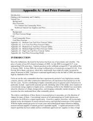
Fig. 10. Single Enthalpy curve and boundaries.<br />
Time-out and Screensaver<br />
When no buttons have been pressed for 10 minutes, the LCD<br />
displays a screen saver, which cycles through the Status<br />
items. Each Status items displays in turn and cycles to the<br />
next item after 5 seconds:<br />
Enthalpy Settings<br />
When the OA temperature, enthalpy and dew point are below<br />
the respective setpoints, the outside air can be used for<br />
economizing. Fig. 10 shows the new single enthalpy<br />
boundaries in the <strong>W7220</strong>. There are 5 boundaries (setpoints<br />
ES1 through ES5), which are defined by dry bulb temperature,<br />
enthalpy and dew point.<br />
Refer to Table 6 for the ENTH CURVE setpoint values.<br />
P1 (T,RH)<br />
DUAL ENTHALPY<br />
HIGH LIMIT<br />
SINGLE ENTHALPY<br />
ES5<br />
P2<br />
(T,RH)<br />
ES4 ES3 ES2 ES1 HL<br />
M32286<br />
Fig. 10 shows the 5 current boundaries. There is also a high<br />
limit boundary for differential enthalpy. The high limit boundary<br />
is ES1 when there are no stages of mechanical cooling<br />
energized and HL when a compressor stage is energized.<br />
Table 6 provides the values for each boundary limit.<br />
Table 6. Single Enthalpy and Dual Enthalpy High Limit Curves.<br />
Enthalpy Temp.<br />
Temp. Enthalpy<br />
Point P1 Point P2<br />
Curve Dry-Bulb (°F) Dewpoint (°F) (btu/lb/da) Temp. °F Humidity %RH Temp. °F Humidity %RH<br />
ES1 80.0 60.0 28.0 80.0 36.8 66.3 80.1<br />
ES2 75.0 57.0 26.0 75.0 39.6 63.3 80.0<br />
ES3 70.0 54.0 24.0 70.0 42.3 59.7 81.4<br />
ES4 65.0 51.0 22.0 65.0 44.8 55.7 84.2<br />
ES5 60.0 48.0 20.0 60.0 46.9 51.3 88.5<br />
HL 86.0 66.0 32.4 86.0 38.9 72.4 80.3
<strong>Economizer</strong> Setup and Configuration<br />
To setup and configure the <strong>Economizer</strong> module, use the<br />
System Setup menu, the Advanced Setup menu (if<br />
necessary), and the Setpoints menu. Refer to Table 7.<br />
Setup and configure the module in the following order:<br />
1. Enter the System Setup parameters.<br />
2. If needed, enter the Advanced Setup parameters.<br />
3. Enter the Setpoint settings.<br />
To make a parameter or setpoint change:<br />
1. Use the � and � buttons to move to the desired menu.<br />
2. Press the ↵ button (Enter) to display to the first<br />
parameter.<br />
3. Use the � and � buttons to move to the desired<br />
parameter.<br />
Menu Parameter<br />
Table 7. Setup and Setpoint Menus.<br />
Parameter<br />
Default<br />
Value<br />
JADE ECONOMIZER MODULE<br />
4. Press the ↵ button (Enter) to select the parameter and<br />
display its value.<br />
5. Use the � and � buttons to change or increase/<br />
decrease the parameter value.<br />
6. Press the ↵ button (Enter) to store the new value for<br />
the parameter.<br />
7. CHANGE STORED displays.<br />
8. Press the ↵ button (Enter) to return to the current menu<br />
parameter.<br />
9. Repeat steps 4 through 8 for each parameter you want<br />
to change.<br />
10. When finished, press the<br />
return to the previous menu.<br />
button (MenuUp/Exit) to<br />
11. Repeat the above steps for each of the three menus -<br />
System Setup, Advanced Setup, and Setpoints.<br />
Parameter<br />
Range and Increment Notes<br />
SYSTEM SETUP INSTALL 01/01/10 Display order = MM/DD/YY<br />
Setting order = DD, MM, then YY.<br />
UNITS DEG ºF ºF or ºC Sets economizer controller in degrees Fahrenheit or<br />
Celsius.<br />
EQUIPMENT CONV CONV<br />
HP(O)<br />
HP(B)<br />
FAN CFM 5000cfm 100 to 15000 cfm;<br />
increment by 100<br />
AUX OUT NONE NONE<br />
ERV<br />
EXH2<br />
SYS<br />
CONV = conventional; enables configuration of<br />
shutdown parameter.<br />
HP(O) = energize heat pump on Cool<br />
HP(B) = energize heat pump on Heat<br />
This is the capacity of the RTU. The value is found<br />
on the label from the RTU manufacturer.<br />
• NONE = not configured (output is not used)<br />
• ERV= Energy Recovery Ventilator<br />
• EXH2 = second damper position relay closure<br />
for second exhaust fan.<br />
• SYS = use output as an alarm signal<br />
FACTORY DEFAULT NO NO or YES Resets all set points to factory defaults when set to<br />
YES. LCD will briefly flash YES and change to NO<br />
but all parameters will change to factory default<br />
values.<br />
ADVANCED SETUP MA LO SET 45ºF 35 to 55 ºF;<br />
increment by 1º<br />
Temp to activate Freeze Protection (close damper<br />
and alarm if temp falls below setup value)<br />
FREEZE POS CLO CLO/MIN Damper position when freeze protection is active<br />
(closed or MIN POS).<br />
CO2 ZERO 0ppm 0 to 500 ppm;<br />
increment by 10<br />
CO2 ppm level to match CO2 sensor start level.<br />
CO2 SPAN 2000ppm 1000 to 3000 ppm;<br />
increment by 50<br />
CO2 ppm span to match CO2 sensor.<br />
STG3 DLY 2.0h 0 to 4.0 hours or OFF;<br />
increment by 0.5<br />
INTERSTG DLY 5 min 1 to 9 minutes<br />
increment by 1<br />
Delay after stage 2 for cool has been active. Turns<br />
on 2nd stage of cooling when economizer is 1st<br />
stage and mechanical cooling is 2nd stage. Allows<br />
three stages of cooling, 1 economizer and 2<br />
mechanical.<br />
OFF = no Stage 3 cooling.<br />
Delay between stages 1 and 2 for cool<br />
15 <strong>62</strong>-0331—01
JADE ECONOMIZER MODULE<br />
Menu Parameter<br />
ADVANCED SETUP<br />
(continued)<br />
SD INPUT OPN OPN<br />
CLO<br />
DCVCAL ENA MAN AUTO<br />
MAN (manual)<br />
SETPOINTS MAT SET 53ºF 38 to 65 ºF;<br />
increment by 1<br />
LOW T LOCK 32ºF -45 to 80 ºF;<br />
increment by 1<br />
DRYBLB SET 63ºF 48 to 80 ºF;<br />
increment by 1<br />
<strong>62</strong>-0331—01 16<br />
Table 7. Setup and Setpoint Menus. (Continued)<br />
Parameter<br />
Default<br />
Value<br />
ENTH CURVE ES3 ES1, ES2, ES3,<br />
ES4, or ES5<br />
DCV SET 1100ppm 500 to 2000 ppm<br />
increment by 100<br />
Indicates shutdown signal from space thermostat or<br />
unitary controller. When controller receives 24 Vac<br />
input on the SD terminal in conventional mode, the<br />
OA damper will open if programmed for OPN and<br />
OA damper will close if programmed for CLO. All<br />
other controls, e.g., fans, etc. will shut off.<br />
Turns on the DCV automatic control of the dampers.<br />
Resets ventilation based on the RA, OA and MA<br />
sensor conditions. See Product Data sheet 63-2700<br />
for details. Requires all 3 RA, OA and MA sensors.<br />
Setpoint determines where the economizer will<br />
modulate the OA damper to maintain the mixed air<br />
temperature.<br />
Setpoint determines outdoor temperature when the<br />
mechanical cooling cannot be turned on. Commonly<br />
referred to as the Compressor lockout.<br />
Setpoint determines where the economizer will<br />
assume outdoor air temperature is good for free<br />
cooling; e.g.; at 63 ºF unit will economizer at <strong>62</strong> ºF<br />
and below and not economize at 64 ºF and above.<br />
There is a a 2 ºF deadband.<br />
Enthalpy boundary “curves” for economizing using<br />
single enthalpy.<br />
See “Enthalpy Settings” on page 14 and Product<br />
Data sheet form 63-2700 for description of enthalpy<br />
curves.<br />
Displays ONLY if a CO2 sensor is connected.<br />
Setpoint for Demand Control Ventilation of space.<br />
Above the setpoint, the OA dampers will modulate<br />
open to bring in additional OA to maintain a space<br />
ppm level below the setpoint.<br />
MIN POS 2.8 V 2 to 10 Vdc Displays ONLY if a CO2 sensor is NOT connected.<br />
VENTMAX 2.8 V 2 to 10 Vdc<br />
or<br />
100 to 9990 cfm<br />
increment by 10<br />
VENTMIN 2.25 V 2 to 10 Vdc<br />
or<br />
100 to 9990 cfm<br />
increment by 10<br />
ERV OAT SP 32ºF 0 to 50 ºF;<br />
increment by 1<br />
EXH1 SET 50% 0 to 100%;<br />
increment by 1<br />
EXH2 SET 75% 0 to 100%;<br />
increment by 1<br />
Parameter<br />
Range and Increment Notes<br />
Displays only if a CO2 sensor is connected.<br />
Used for Vbz (ventilation max cfm) setpoint.<br />
Displays 2 to 10 V if
CHECKOUT<br />
Inspect all wiring connections at the <strong>Economizer</strong> module’s<br />
terminals, and verify compliance with the installation wiring<br />
diagrams.<br />
For checkout, review the Status of each configured parameter<br />
and perform the Checkout tests.<br />
NOTE: See “Interface Overview” on page 9 for information<br />
about menu navigation and use of the keypad.<br />
WARNING<br />
Electrical Shock Hazard.<br />
Can cause severe injury, death or property<br />
damage.<br />
Disconnect power supply before beginning wiring or<br />
making wiring connections, to prevent electrical shock<br />
or equipment damage.<br />
If any wiring changes are required, first be sure to<br />
remove power from the <strong>Economizer</strong> module before<br />
starting work. Pay particular attention to verifying the<br />
power connection (24 Vac).<br />
Power Up<br />
After the module is mounted and wired, apply power.<br />
Menu Parameter<br />
Parameter<br />
Default<br />
Value<br />
Table 8. Status Menu.<br />
JADE ECONOMIZER MODULE<br />
Power Up Delay<br />
Upon power up (or after a power outage or brownout), the<br />
<strong>W7220</strong> controller module begins a 5 minute power up delay<br />
before enabling mechanical cooling.<br />
Initial Menu Display<br />
On initial start up, Honeywell displays on the first line and<br />
<strong>Economizer</strong> <strong>W7220</strong> on the second line. After a brief pause,<br />
the revision of the software appears on the first line and the<br />
second line will be blank.<br />
Power Loss (Outage or Brownout)<br />
All setpoints and advanced settings are restored a after any<br />
power loss or interruption.<br />
NOTE: If power goes below 18 Vac, the <strong>W7220</strong> controller<br />
module assumes a power loss and the 5 minute<br />
power up delay will become functional when power<br />
returns above 18 Vac.<br />
Status<br />
Use the Status menu (see Table 8) to check the parameter<br />
values for the various devices and sensors configured.<br />
NOTE: See “Interface Overview” on page 9 for information<br />
about menu navigation and use of the keypad.<br />
a All settings are stored in non-volatile flash memory.<br />
Parameter<br />
Range and Increment Notes<br />
STATUS ECON AVAIL NO YES/NO YES = economizing available; the system can use outside<br />
air for free cooling when required.<br />
ECONOMIZING NO YES/NO YES = outside air being used for 1st stage cooling.<br />
OCCUPIED NO YES/NO YES = OCC signal received from space thermostat or<br />
unitary controller.<br />
YES = 24 Vac on terminal OCC<br />
No = 0 Vac on terminal OCC.<br />
HEAT PUMP n/a a COOL<br />
HEAT<br />
Displays COOL or HEAT when system is set to heat pump<br />
(non-conventional)<br />
COOL Y1-IN OFF ON/OFF Y1-I signal from space thermostat or unitary controller for<br />
cooling stage 1.<br />
ON = 24 Vac on term Y1-I<br />
OFF = 0 Vac on term Y1-I<br />
COOL Y1-OUT OFF ON/OFF Cool Stage 1 Relay Output to stage 1 mechanical cooling<br />
(Y1-OUT terminal).<br />
COOL Y2-IN OFF ON/OFF Y2-I signal from space thermostat or unitary controller for<br />
second stage cooling.<br />
ON = 24 Vac on term Y2-I<br />
OFF = 0 Vac on term Y2-I<br />
COOL Y2-OUT OFF ON/OFF Cool Stage 2 Relay Output to mechanical cooling (Y2-<br />
OUT terminal).<br />
MA TEMP _ _._ ºF 0 to 140 ºF Displays value of measured mixed air from MAT sensor.<br />
Displays --.- if not connected, short, or out- of-range.<br />
17 <strong>62</strong>-0331—01
JADE ECONOMIZER MODULE<br />
Menu Parameter<br />
STATUS (continued) DA TEMP _ _._ ºF 0 to 140 ºF Displays when Discharge Air Sylk Bus sensor is<br />
connected and displays measured discharge air<br />
temperature.<br />
Displays --.-°F if sensor sends invalid value, if not<br />
connected, short or out-of-range.<br />
OA TEMP _ _._ ºF -40 to 140 ºF Displays measured value of outdoor air temperature.<br />
Displays --°F if sensor sends invalid value, if not<br />
connected, short or out-of-range.<br />
OA HUM _ _ % 0 to 100% Displays measured value of outdoor humidity from QA<br />
Sylkbus sensor. Displays --% if not connected, short, or<br />
out- of-range.<br />
RA TEMP _ _._ ºF 0 to 140 ºF Displays measured value of return air temperature from<br />
RAT sensor. Displays --°F if sensor sends invalid value, if<br />
not connected, short or out-of-range.<br />
RA HUM _ _ % 0 to 100% Displays measured value of return air humidity from RA<br />
Sylkbus sensor. Displays --% if sensor sends invalid<br />
value, if not connected, short or out-of-range.<br />
IN CO2 _ _ _ ppm 0 to 2000 ppm Displays value of measured CO2 from CO2 sensor.<br />
Invalid if not connected, short or out-of-range.<br />
DCV STATUS n/a ON/OFF Displays ON if above setpoint and OFF if below setpoint,<br />
and ONLY if a CO2 sensor is connected.<br />
DAMPER OUT 2.0V 2.0 to 10.0 V Displays voltage output to the damper actuator.<br />
EXH1 OUT OFF ON/OFF Output of EXH1 terminal.<br />
ON = relay closed; OFF = relay open.<br />
EXH2 OUT OFF ON/OFF Output of AUX terminal; displays only if AUX = EXH2<br />
ERV OFF ON/OFF Output of AUX terminal; displays only if AUX = ERV<br />
MECH COOL ON 0 0, 1, or 2 Displays stage of mechanical cooling that is active.<br />
a n/a = not applicable<br />
<strong>62</strong>-0331—01 18<br />
Table 8. Status Menu. (Continued)<br />
Parameter<br />
Default<br />
Value<br />
Parameter<br />
Range and Increment Notes
Checkout Tests<br />
Use the Checkout menu (Table 9) to test the damper<br />
operation and any configured outputs. Only items that are<br />
configured are shown in the Checkout menu.<br />
NOTE: See “Interface Overview” on page 9 for information<br />
about menu navigation and use of the keypad.<br />
To perform a Checkout test:<br />
1. Scroll to the desired test in the Checkout menu using<br />
the � and � buttons.<br />
2. Press the ↵ button to select the item.<br />
3. RUN? appears.<br />
4. Press the ↵ button to start the test.<br />
5. The unit pauses and then displays IN PROGRESS.<br />
6. When the test is complete, DONE appears.<br />
7. When all parameters have been tested, press the<br />
button (Menu up) to end the test (e.g. turn off the relay).<br />
The checkout tests can all be performed at the time of<br />
installation or any time during the operation of the system as a<br />
test that the system is operable.<br />
JADE ECONOMIZER MODULE<br />
Table 9. Checkout Menu.<br />
Checkout Item Checkout Test<br />
DAMPER VMIN-HS Positions damper to VMIN position<br />
DAMPER VMAX-HS Positions damper to VMAX position<br />
DAMPER OPEN Positions damper to the full open position.<br />
Exhaust fan contacts enable during the<br />
DAMPER OPEN test. Make sure you pause in<br />
this mode to allow for exhaust contacts to<br />
energize due to the delay in the system.<br />
DAMPER CLOSE Positions damper to the fully closed position.<br />
CONNECT Y1-O Closes the Y1-O relay (Y1-O).<br />
See CAUTION on this page<br />
CONNECT Y2-O Closes the Y2-O relay (Y2-O).<br />
See CAUTION on this page<br />
CONNECT AUX Energizes the AUX output. If Aux setting is:<br />
• NONE – no action taken<br />
• ERV – 24 Vac out. Turns on or signals an<br />
ERV that the conditions are not good for<br />
economizing but are good for ERV<br />
operation.<br />
• SYS – 24 Vac out. Issues a system alarm.<br />
CAUTION<br />
Equipment damage may result.<br />
Be sure to allow enough time for compressor startup<br />
and shutdown between checkout tests so that you do<br />
not short-cycle the compressors.<br />
19 <strong>62</strong>-0331—01
JADE ECONOMIZER MODULE<br />
TROUBLESHOOTING<br />
Power Loss (Outage or Brownout)<br />
All setpoints and advanced settings are restored a after any<br />
power loss or interruption.<br />
NOTE: If power goes below 18 Vac, the <strong>W7220</strong> controller<br />
module assumes a power loss and the 5 minute<br />
power up delay will become functional when power<br />
returns above 18 Vac.<br />
Alarms<br />
The <strong>Economizer</strong> module provides alarm messages that<br />
display on the 2-line LCD.<br />
NOTE: Upon power up, the module waits several seconds<br />
before checking for alarms. This allows time for all<br />
the configured devices (e.g. sensors, actuator) to<br />
become operational.<br />
If one or more alarms are present and there has been no<br />
keypad activity for at least 5 minutes, the Alarms menu<br />
displays and cycles through the active alarms.<br />
You can also navigate to the Alarms menu at any time.<br />
a All settings are stored in non-volatile flash memory.<br />
Automation and Control Solutions<br />
Honeywell International Inc.<br />
1985 Douglas Drive North<br />
Golden Valley, MN 55422<br />
Honeywell Limited-Honeywell Limitée<br />
35 Dynamic Drive<br />
Toronto, Ontario M1V 4Z9<br />
customer.honeywell.com<br />
Table 10. Alarms Menu.<br />
Menu Alarm<br />
ALARMS(_) MA T SENS ERR<br />
CO2 SENS ERR<br />
OA T SENS ERR<br />
DA ENTHL ERR<br />
SYS ALARMa NOTES:<br />
1. The Alarms menu displays only when alarm(s)<br />
are active and includes the number of active<br />
alarms in parenthesis ().<br />
2. The alarms listed are a few examples. Additional<br />
alarms display depending on the parameter<br />
settings and configuration.<br />
a When AUX is set to SYS and there is any alarm (e.g., failed sensors,<br />
etc.), the AUX terminal has 24 Vac out and the LCD displays the SYS<br />
ALARM.<br />
Clearing Alarms<br />
Once the alarm has been identified and the cause has been<br />
removed (e.g. replaced faulty sensor), the alarm can be<br />
cleared from the display.<br />
To clear an alarm, perform the following:<br />
1. Navigate to the desired alarm.<br />
2. Press the ↵ button.<br />
3. ERASE? displays.<br />
4. Press the ↵ button.<br />
5. ALARM ERASED displays.<br />
6. Press the button (MenuUp/Exit) to complete the<br />
action and return to the previous menu.<br />
NOTE: If an the alarm still exists after you clear it, it redisplays<br />
within 5 seconds.<br />
® U.S. Registered Trademark<br />
© 2010 Honeywell International Inc.<br />
<strong>62</strong>-0331—01 M.S. 09-10<br />
Printed in U.S.A.