
You also want an ePaper? Increase the reach of your titles
YUMPU automatically turns print PDFs into web optimized ePapers that Google loves.
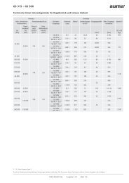
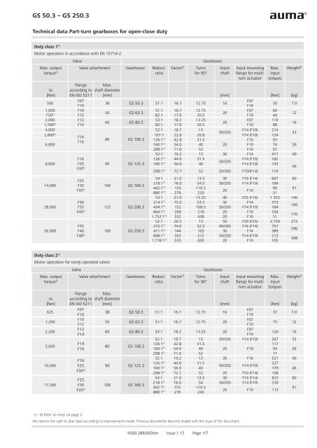
GS 50.3 – GS 250.3<br />
Technical data Part-turn gearboxes for open-close duty<br />
Duty class 1 1)<br />
Motor operation in accordance with EN 15714-2.<br />
Valve<br />
Max. output Valve attachment Gearboxes Reduct.<br />
torque 2) ratio<br />
Factor 3)<br />
Turns<br />
for 90°<br />
Gearboxes<br />
Input<br />
shaft<br />
Input mounting<br />
fl ange for <strong>multiturn</strong><br />
actuator<br />
Max.<br />
input<br />
torques<br />
Weight 4)<br />
Flange Max.<br />
to according to shaft diameter<br />
[Nm] EN ISO 5211 [mm] [mm] [Nm] [kg]<br />
500<br />
F07<br />
F07<br />
38 GS 50.3 51:1 16.7 12.75 16<br />
F10<br />
F10<br />
30 7.0<br />
1,000 F10<br />
51:1 16.7 12.75<br />
F07 60<br />
50 GS 63.3<br />
20<br />
750 5) F12<br />
82:1 17.0 20.5 F10 44<br />
12<br />
2,000 F12<br />
53:1 18.2 13.25<br />
F07 110<br />
60 GS 80.3<br />
20<br />
1,500 5) F14<br />
82:1 17.0 20.5 F10 88<br />
16<br />
4,000<br />
52:1 18.7 13<br />
F14 (F10) 214<br />
30/(20)<br />
33<br />
2,800 5) 107:1 22.6 26.8 F14 (F10) 124<br />
F14<br />
80 GS 100.3 126:1<br />
F16<br />
42.8 31.5<br />
F10 93<br />
4,000<br />
160:1 7) 54.0 40 20 F10 74 39<br />
208:1 7) 71.0 52 F10 57<br />
52:1 19.2 13 30 F14 417 40<br />
8,000<br />
F16<br />
126:1 7) 44.0 31.5<br />
F14 (F10) 182<br />
30/(20)<br />
F25 90 GS 125.3 160:1 7) 56.0 40 F14 (F10) 143<br />
F30 6) 208:1 7) 72.7 52 20/(30) F10/(F14) 110<br />
46<br />
14,000<br />
28,000<br />
56,000<br />
F25<br />
F30 100 GS 160.3<br />
F35 6)<br />
F30<br />
F35 125 GS 200.3<br />
F40 6)<br />
F35<br />
F40 160 GS 250.3<br />
F48 6)<br />
54:1 21.0 13.5 30 F16 (F14) 667 80<br />
218:1 7) 76.0 54.5 30/(20) F14 (F10) 184<br />
442:1 7) 155 110.5<br />
90 91<br />
20 F10<br />
880:1 7) 276 220 51<br />
53:1 21.0 13.25 40 F25 (F16) 1 353 140<br />
214:1 7) 75.0 53.5 30 F14 373<br />
434:1 7) 152 108.5 30/(20) F14 (F10) 184<br />
160<br />
864:1 7) 268 216 20 F10 104<br />
1,752:1 7) 552 438 20 F10 51<br />
170<br />
52:1 20.3 13 50 F30 (F25) 2,759 273<br />
210:1 7) 74.0 52.5 40/(30) F16 (F14) 757<br />
411:1 7) 144 103 30 F14 389<br />
296<br />
848:1 7) 263 212 30/(20) F14 (F10) 213<br />
1,718:1 7) 533 430 20 F10 105<br />
308<br />
Duty class 2 1)<br />
Motor operation for rarely operated valves<br />
Valve<br />
Max. output Valve attachment Gearboxes Reduct.<br />
torque 2) ratio<br />
to<br />
[Nm]<br />
625<br />
1,250<br />
2,200<br />
5,000<br />
10,000<br />
17,500<br />
Factor 3)<br />
Turns<br />
for 90°<br />
Gearboxes<br />
Input<br />
shaft<br />
Input mounting<br />
fl ange for <strong>multiturn</strong><br />
actuator<br />
Max.<br />
input<br />
torques<br />
Weight 4)<br />
Flange Max.<br />
according to shaft diameter<br />
EN ISO 5211 [mm] [mm] [Nm] [kg]<br />
F07<br />
F07<br />
38 GS 50.3 51:1 16.7 12.75 16<br />
37 7.0<br />
F10<br />
F10<br />
F10<br />
F07<br />
50 GS 63.3 51:1 16.7 12.75 20<br />
75 12<br />
F12<br />
F12<br />
F14<br />
F14<br />
F16<br />
F10<br />
60 GS 80.3 53:1 18.2 13.25 20<br />
F07<br />
F10<br />
120 16<br />
52:1 18.7 13 30/(20) F14 (F10) 267 33<br />
80 GS 100.3<br />
126:1 7) 42.8 31.5<br />
117<br />
160:1 7) 54.0 40 20 F10 93 39<br />
208:1 7) 71.0 52 71<br />
52:1 19.2 13 30 F16 521 40<br />
126:1 7) 44.0 31.5<br />
227<br />
30/(20) F14 (F10)<br />
160:1 7) 56.0 40 179 46<br />
208:1 7) 72.7 52 20 F10 (F14) 138<br />
54:1 21.0 13.5 30 F16 (F14) 833 80<br />
218:1 7) 76.0 54 30/(20) F14 (F10) 230<br />
442:1 7) 155 110.5<br />
91<br />
20 F10 113<br />
880:1 7) 276 220<br />
F16<br />
F25 90 GS 125.3<br />
F30 6)<br />
F25<br />
F30 100 GS 160.3<br />
F35 6)<br />
1) – 8) Refer to notes on page 3.<br />
We reserve the right to alter data according to improvements made. Previous documents become invalid with the issue of this document.<br />
Y000.288/003/en Issue 1.15 Page 1/7
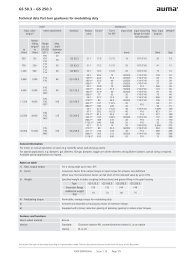
GS 50.3 – GS 250.3<br />
Technical data Part-turn gearboxes for open-close duty<br />
Valve<br />
Max. output Valve attachment Gearboxes Reduct.<br />
torque 2) ratio<br />
to<br />
[Nm]<br />
35,000<br />
70,000<br />
Flansch nach<br />
EN ISO<br />
5211<br />
Max.<br />
shaft diameter<br />
Factor 3)<br />
Turns<br />
for 90°<br />
Gearboxes<br />
Input<br />
shaft<br />
Input mounting<br />
fl ange for <strong>multiturn</strong><br />
actuator<br />
Max.<br />
input<br />
torques<br />
Weight 4)<br />
[mm] [mm] [Nm] [kg]<br />
53:1 21.0 13.25 40 F25 (F16) 1,691 140<br />
214:1 7) 75.0 53.5 30 F14 467<br />
434:1 7) 152 108.5 30/(20) F14 (F10) 230<br />
160<br />
864:1 7) 268 216 30 F14 131<br />
1,752:1 7) 552 438 20 F10 63<br />
170<br />
52:1 20.3 13 50 F30 (F25) 3,448 273<br />
210:1 7) 74.0 52.5 40/(30) F16 (F14) 946<br />
411:1 7) 144 103 30 F14 486<br />
296<br />
848:1 7) 263 212 30/(20) F14 (F10) 266<br />
1,718:1 7) 533 430 20 F14 131<br />
308<br />
F30<br />
F35 125 GS 200.3<br />
F40 6)<br />
F35<br />
F40 160 GS 250.3<br />
F48 6)<br />
Duty class 3 1)<br />
Manual operation in accordance with EN 1074-2<br />
Max. output Valve attachment Gearboxes Reduction<br />
torque 2) ratio<br />
to<br />
[Nm]<br />
Flange<br />
according to<br />
EN ISO 5211<br />
Max.<br />
shaft diameter<br />
Factor 3) Input shaft Max. input<br />
torques<br />
Handwheel<br />
Ø 8)<br />
Manual<br />
force<br />
Weight 4)<br />
[mm] [mm] [Nm] [mm] [N] [kg]<br />
750<br />
160 561<br />
F07<br />
38 GS 50.3 51:1 16.7 16 45 200 449<br />
F10<br />
250 359<br />
7.0<br />
250 720<br />
1,500<br />
51:1 16.7<br />
90<br />
F10<br />
315 570<br />
50 GS 63.3<br />
20<br />
F12<br />
200 441<br />
750 5) 82:1 17.0 44<br />
250 353<br />
12<br />
3,000<br />
53:1 18.2<br />
165 400 824<br />
F12<br />
60 GS 80.3<br />
20<br />
315 560<br />
1,500 5) F14<br />
82:1 17.0 88<br />
400 441<br />
16<br />
6 000<br />
52:1 18.7<br />
321 800 802<br />
2,800 5) 107:1 22.6<br />
30/(20)<br />
400 619 33<br />
124<br />
500 496<br />
126:1<br />
F14<br />
42.8<br />
140 400 701<br />
80 GS 100.3<br />
315 705<br />
F16<br />
160:1 7) 54.0 111<br />
400 556<br />
6 000<br />
30<br />
39<br />
250 679<br />
208:1 7) 71.0 85 315 539<br />
400 424<br />
12,000<br />
17,500<br />
35,000<br />
70,000<br />
F16<br />
F25 90 GS 125.3<br />
F30 6)<br />
F25<br />
F30 100 GS 160:3<br />
F35 6)<br />
F30<br />
F35 125 GS 200.3<br />
F40 6)<br />
F35<br />
F40 160 GS 250.3<br />
F48 6)<br />
126:1 7) 44.0<br />
273<br />
630 866<br />
800 682<br />
30/(20)<br />
500 857<br />
160:1 7) 56.0 214 630 680<br />
800 535<br />
208:1 7) 72.7 20 165 400 825<br />
218:1 7) 76.0 30/(20) 230<br />
630 731<br />
800 576<br />
442:1 7) 155<br />
113<br />
315 717<br />
400 565<br />
20<br />
200 634<br />
880:1 7) 276 63 250 507<br />
315 403<br />
434:1 7) 152 30/(20) 230<br />
630 731<br />
800 576<br />
864:1 7) 268 30 131 400 653<br />
1,752:1 7) 552 20 63<br />
315 403<br />
400 317<br />
848:1 7) 263 30/(20) 266<br />
630 845<br />
800 665<br />
1,718:1 7) 533 20 131 400 657<br />
46<br />
91<br />
160<br />
170<br />
308<br />
1) – 8) Refer to notes on page 3.<br />
We reserve the right to alter data according to improvements made. Previous documents become invalid with the issue of this document.<br />
Y000.288/003/en Issue 1.15 Page 2/7
GS 50.3 – GS 250.3<br />
Technical data Part-turn gearboxes for open-close duty<br />
General information<br />
For motor or manual operation of valves (e.g. butterfl y valves, ball and plug valves).<br />
For special applications, e.g. dampers, gas diverters, fl ue gas dampers, toggle arm driven diverters and guillotine isolators, special sizing is required and<br />
the specifi c technical data apply. Available special applications on request.<br />
Notes to table on pages 1 + 2<br />
1) Duty class For further information on lifetime, refer to "Lifetime for motor operation" and "Lifetime for manual operation"<br />
on page 6.<br />
2) Max. output torque For a swing angle up to max. 90°.<br />
Duty class 3 can exclusively be used for manual operation. Please refer to page 2 for the pertaining handwheel<br />
size.<br />
3) Factor Conversion factor from output torque to input torque for actuator size defi nition<br />
When new, the transmission factor can fall short of the indicated value by up to 10 %.<br />
4) Weight Indicated weight includes unfi nished coupling and grease fi lling in the gear housing.<br />
Type GS 125.3 GS 160.3 GS 200.3 GS 250.3<br />
Extension fl ange F30 F35 F40 F48<br />
Additional weight<br />
[kg]<br />
5) Toothing properties do not allow for higher loads.<br />
18 33 48 75<br />
6) Screwed and dowelled to housing by means of extension fl ange.<br />
7) Equipped with primary reduction gearing of planetary gearing to reduce input torques.<br />
8. Available handwheel diameters in accordance with EN 12570.<br />
Features and functions<br />
Worm wheel material<br />
Spheroidal cast iron<br />
Version Standard: Clockwise rotation RR, counterclockwise rotation LL as an option<br />
Option:<br />
RL or LR<br />
Housing material Standard: Cast iron (GJL-250)<br />
Option:<br />
Spheroidal cast iron (GJS-400-15)<br />
Self-locking<br />
End stops<br />
Strength of end stop<br />
The gearboxes are self-locking when at standstill under normal service conditions; strong vibration may cancel<br />
the self-locking effect. While in motion, safe braking is not guaranteed. If this is required, a separate brake<br />
must be used.<br />
Positive for both end positions by travelling nut, sensitive adjustment<br />
Guaranteed strength of end stop (in Nm) for input side operation<br />
Type GS 50.3 GS 63.3 GS 80.3 GS 100.3<br />
Reduction<br />
51:1 51:1 53:1 52:1 126:1 160:1 208:1<br />
ratio<br />
[Nm] 250 450 450 1350 625 500 250<br />
Type GS 125.3 GS 160.3<br />
Reduction<br />
52:1 126:1 160:1 208:1 54:1 218:1 442:1 880:1<br />
ratio<br />
[Nm] 1350 625 500 250 3200 900 450 250<br />
Type GS 200.3 GS 250.3<br />
Reduction<br />
ratio<br />
53:1 214:1 434:1 864:1 1,752:1 52:1 210:1 411:1 848:1 1,718:1<br />
[Nm] 8000 2000 1000 500 250 8000 2000 1000 500 250<br />
Swing angle GS 50.3 – GS 125.3 Standard: Fixed swing angle between 10° and max. 100°; set in the factory to 92° unless ordered<br />
otherwise.<br />
Options:<br />
Adjustable in steps of:<br />
10° – 35°, 35° – 60°, 60° – 80°, 80° – 100°, 100° – 125°, 125° – 150°, 150° – 170°,<br />
170° – 190°<br />
Swing angle > 190°, refer to Technical data GS 50.3 – GS 250.3 for modulating duty and<br />
shorter operating times<br />
We reserve the right to alter data according to improvements made. Previous documents become invalid with the issue of this document.<br />
Y000.288/003/en Issue 1.15 Page 3/7
GS 50.3 – GS 250.3<br />
Technical data Part-turn gearboxes for open-close duty<br />
Swing angle GS 160.3 – GS 250.3 Standard: Adjustable 80° – 100°; set in the factory to 92° unless ordered otherwise.<br />
Options:<br />
Adjustable in steps of:<br />
0° – 20°, 20° – 40°, 40° – 60°, 60° – 80°, 90° – 110°, 110° – 130°, 130° – 150°, 150° –<br />
170°, 170° – 190°<br />
Swing angle > 190°, refer to Technical data GS 50.3 – GS 250.3 for modulating duty and<br />
shorter operating times<br />
Mechanical position indicator Standard: Pointer cover for continuous position indication<br />
Options:<br />
• Sealed pointer cover for horizontal outdoor installation (not available for GS 50.3)<br />
• Protection cover for buried services instead of pointer cover (without mechanical position<br />
indicator)<br />
• Sealed pointer cover with air vent, not available for GS 50.3<br />
Observe Information sheet Enclosure protection IP68 for part-turn gearboxes<br />
Input shaft Cylindrical with parallel key according to DIN 6885-1 (refer to table on pages 1 and 2)<br />
Operation<br />
Motor operation<br />
Type of duty<br />
Maximum permissible input speeds<br />
and operating times<br />
• Via electric multi-turn actuator<br />
• Input mounting fl anges for multi-turn actuator (refer to table pages 1 and 2)<br />
Short-time duty S2 - 15 min<br />
Class A according to EN 15714-2: OPEN-CLOSE<br />
Class B according to EN 15714-2: Inching/positioning or positioning duty.<br />
Type GS 50.3 GS 63.3 GS 80.3 GS 100.3<br />
Reduction ratio 51:1 51:1 82:1 53:1 82:1 52:1 107:1 126:1 160:1 280:1<br />
Max. permissible<br />
input speed<br />
[rpm]<br />
Fastest operating<br />
time for 90° [s]<br />
108 108 108 108 216<br />
7 7 11 7 11 7 15 9 11 19<br />
Type GS 125.3 GS 160.3<br />
Reduction ratio 52:1 126:1 160:1 208:1 54:1 218:1 442:1 880:1<br />
Max. permissible<br />
input speed<br />
[rpm]<br />
Fastest operating<br />
time for 90° [s]<br />
108 216 108 216<br />
7 9 11 19 8 15 31 61<br />
Type GS 200.3 GS 250.3<br />
Reduction ratio 53:1 214:1 434:1 864:1 1,752:1 52:1 210:1 411:1 848:1 1 718:1<br />
Max. permissible<br />
input speed<br />
[rpm]<br />
Fastest operating<br />
time for 90° [s]<br />
108 216 108 216<br />
7 15 30 60 122 7 15 29 59 119<br />
Shorter operating times can be achieved with worm wheels made of bronze, refer to Technical data<br />
GS 50.3 – GS 250.3 for modulating duty and shorter operating times.<br />
Due to gear tooth geometry and the material characteristics of bronze, worm gearboxes with a worm wheel<br />
made of bronze can transmit lower torques<br />
Calculation of operating time for a 90° swivel movement<br />
Oper. time for 90° [s] =<br />
Reduction ratio [i]<br />
n [input speed in rpm]<br />
15<br />
Calculation of the operating time for a swivel movement θ [°]:<br />
<br />
Swing angle θ [°] <br />
6 <br />
We reserve the right to alter data according to improvements made. Previous documents become invalid with the issue of this document.<br />
Y000.288/003/en Issue 1.15 Page 4/7
GS 50.3 – GS 250.3<br />
Technical data Part-turn gearboxes for open-close duty<br />
Manual operation Standard:<br />
Options:<br />
• Handwheel made of aluminium with electrophoretic coating<br />
• Handwheel with ball handle<br />
• Handwheel made of GJL-200 with electrophoretic coating and painting<br />
• Handwheel lockable<br />
• WSH for signalling position and end positions<br />
Deflection of the input shaft<br />
Defl ection<br />
90° defl ection of the input shaft<br />
Combination with GK bevel gearbox directly mounted on GS or planetary stage possible, refer to Mounting<br />
positions Part-turn gearboxes with multi-turn actuators<br />
Base and lever<br />
Not suitable for duty class 3<br />
Base<br />
Lever<br />
Ball joints<br />
Made of spheroidal cast iron; for mounting to base, 4 holes for fastening screws are available.<br />
Made of spheroidal cast iron; with 2 or 3 bores for fi xing lever arrangement. Considering the ambient conditions,<br />
the lever may be mounted to the output shaft in any desired position.<br />
Two ball joints matching the lever, as an option including lock nuts and 2 welding nuts; suitable for pipe<br />
according to dimension sheet<br />
Mechanical position indicator Standard: No position indicator (protection cover)<br />
Option:<br />
Pointer cover instead of protection cover for continuous position indication<br />
Valve attachment<br />
Valve attachment<br />
Spigot<br />
Bore for locating pins (option)<br />
Dimensions according to EN ISO 5211: The maximum torques according to EN ISO 5211 mounting fl anges<br />
are to be met.<br />
Flanges with spigot, recess or plane fl anges are available. Up to GS 125.3, spigots are implemented by means<br />
of spigot rings. From GS 160.3 to GS 250.3, recesses and spigots are directly integrated into the housing.<br />
Two bore for locating pins shifted by 180° Locating pins are not included in the delivery<br />
Type GS 80.3 GS 100.3 GS 125.3 GS 160.3<br />
Flange<br />
according to<br />
EN ISO 5211<br />
F12 F14 F14 F16 F16 F25 F30 F25 F30 F35<br />
Housing material GJS GJS GJS GJS GJL GJL GJL GJL GJL GJL<br />
Type GS 200.3 GS 250.3<br />
Flange<br />
according to<br />
EN ISO 5211<br />
F30 F35 F40 F35 F40 F48<br />
Housing material GJL GJL GJL GJL GJL GJL<br />
Refer to dimension drawing U4.4135. Further pitch circle diameters and bore depths for locating pins on<br />
request.<br />
Splined coupling for connection to the<br />
valve shaft<br />
Standard:<br />
Options:<br />
• Without bore or pilot bore from GS 160.3<br />
• Worm gearbox can be mounted on coupling<br />
Finish machining with bore and keyway, square bore or two-fl at with grub screw for secure<br />
fi xing to valve shaft.<br />
Service conditions<br />
Mounting position<br />
Any position<br />
Ambient temperature Standard: –40 °C to +80 °C<br />
Options: –60 °C to +60 °C<br />
0 °C to +120 °C<br />
Enclosure protection according to<br />
EN 60529<br />
Standard:<br />
Option:<br />
IP68, dust-tight and water-tight up to max. 8 m head of water<br />
IP68-20, dust-tight and water-tight up to max. 20 m head of water<br />
We reserve the right to alter data according to improvements made. Previous documents become invalid with the issue of this document.<br />
Y000.288/003/en Issue 1.15 Page 5/7
GS 50.3 – GS 250.3<br />
Technical data Part-turn gearboxes for open-close duty<br />
Corrosion protection Standard: GS 50.3 – GS 80.3: KS<br />
GS 100.3 – GS 250.3: KN<br />
Option:<br />
KN<br />
KS<br />
KX<br />
GS 50.3 – GS 80.3: KX<br />
GS 100.3 – GS 250.3: KS/KX<br />
Suitable for installation in industrial units, in water or power plants with a low pollutant<br />
concentration<br />
Suitable for use in areas with high salinity, almost permanent condensation, and high pollution.<br />
Suitable for use in areas with extremely high salinity, permanent condensation, and high pollution.<br />
Finish coating GS 50.3 – GS 80.3:<br />
GS 100.3 – GS 250.3:<br />
Powder coating<br />
Two-component iron-mica combination<br />
Colour Standard: AUMA silver-grey (similar to RAL 7037)<br />
Option:<br />
Available colours on request<br />
AUMA load profi le<br />
Peak load (max. output torque)<br />
Torque<br />
Mean load (basic load)<br />
35 %<br />
0 %<br />
35 %<br />
0° 9°<br />
Swivel movement<br />
90°<br />
Swing angle<br />
AUMA worm gearboxes meet or even exceed the lifetime requirements of EN 15714-2.<br />
Lifetime for motor operation<br />
in accordance with AUMA load profi le<br />
Duty class 1: Lifetime for 90° swivel movement Meets the lifetime requirement of EN 15714-2<br />
Gearbox size GS 50.3/<br />
GS 63.3<br />
Number of cycles<br />
for max. torque<br />
GS 80.3/<br />
GS100.3<br />
GS 125.3 –<br />
GS 200.3<br />
GS 250.3<br />
10,000 5,000 2,500 1,200<br />
Lifetime for larger swing angle on request<br />
Duty class 2: Lifetime for 90° swivel movement for valves which are rarely operated.<br />
Gearbox size GS 50.3/<br />
GS 63.3<br />
GS 80.3/<br />
GS100.3<br />
GS 125.3 –<br />
GS 200.3<br />
GS 250.3<br />
Number of cycles<br />
for max. torque<br />
1,000<br />
Lifetime for larger swing angle on request<br />
Lifetime in manual operation Duty class 3: Meets the lifetime requirement of EN 1074-2<br />
Limit sensing for signalling position and end positions<br />
Valve position indicators<br />
• WSG valve position indicator (hall sensors) for position and end position signalling to ensure precise and<br />
low-backlash feedback for swing angles ranging between 82° and 98°.<br />
• WGD valve position indicator (counter gear mechanism) for position and end position signalling for swing<br />
angles > 180°<br />
We reserve the right to alter data according to improvements made. Previous documents become invalid with the issue of this document.<br />
Y000.288/003/en Issue 1.15 Page 6/7
GS 50.3 – GS 250.3<br />
Technical data Part-turn gearboxes for open-close duty<br />
Special features for use in potentially explosive atmospheres in accordance with ATEX 94/9/EC<br />
Type of duty<br />
Maximum 3 cycles (OPEN - CLOSE - OPEN) in accordance with AUMA load profi le (90° swivel movement) and<br />
maximum permissible input speeds, or with mean constant output torques according to table:<br />
Gearbox size GS 50.3 GS 63.3 GS 80.3 GS 100.3 GS 125.3<br />
Reduction ratio - 51:1 82:1 53:1 82:1 - 107:1 -<br />
Average output torque<br />
[Nm]<br />
250 500 375 1,000 750 2,000 1,400 4,000<br />
Ambient temperature Duty classes 1 and 3<br />
Gearbox size GS 160.3 GS 200.3 GS 250.3<br />
Average output torque<br />
8,000 16,000 32,000<br />
[Nm]<br />
Standard:<br />
Options:<br />
–40 °C to +60 °C (II2G c IIC T4; II2D c T130 °C)<br />
–60 °C to +60 °C (II2G c IIC T4; II2D c T130 °C)<br />
–40 °C to +40 °C (II2G c IIC T4; II2D c T130 °C)<br />
–40 °C to +80 °C (II2G c IIC T3; II2D c T190 °C)<br />
0 °C to +120 °C (II2G c IIC T3; II2D c T190 °C)<br />
–20 °C to +40 °C (IM2 c)<br />
Duty class 2<br />
Standard:<br />
Options:<br />
–40 °C to +60 °C (II2G c IIC T3; II2D c T190 °C); T4 on request with individual test<br />
–60 °C to +40 °C (II2G c IIC T4; II2D c T130 °C)<br />
–60 °C to +60 °C (II2G c IIC T3; II2D c T190 °C); T4 on request with individual test<br />
–40 °C to +40 °C (II2G c IIC T4; II2D c T130 °C)<br />
–40 °C to +80 °C (II2G c IIC T3; II2D c T190 °C)<br />
–20 °C to +40 °C (IM2 c)<br />
Further temperature classes or loads exceeding the average torque of the AUMA load profi le on request.<br />
Further information<br />
EU Directives<br />
Reference documents<br />
ATEX Directive: (94/9/EC)<br />
Machinery Directive: (2006/42/EC)<br />
Product description Electric actuators for industrial valve automation<br />
Dimensions GS 50.3 – GS 125.3, GS 160.3 – GS 250.3<br />
Technical data SA 07.2 – SA 16.2 with 3-phase AC motors<br />
Technical data WSG 90.1<br />
Technical data WGD 90.1<br />
Technical data WSH 10.2 – WSH 16.2<br />
Technical data Part-turn gearboxes Operating times for different reduction ratios and input speeds<br />
Information sheet Enclosure protection IP68 for part-turn gearboxes<br />
We reserve the right to alter data according to improvements made. Previous documents become invalid with the issue of this document.<br />
Y000.288/003/en Issue 1.15 Page 7/7