
Create successful ePaper yourself
Turn your PDF publications into a flip-book with our unique Google optimized e-Paper software.
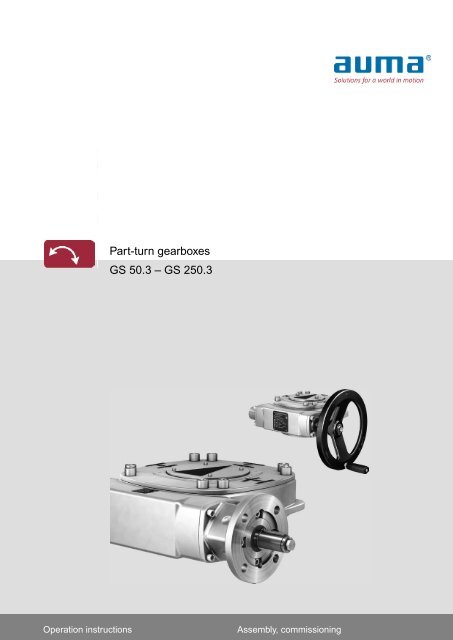
Part-turn gearboxes<br />
<strong>GS</strong> <strong>50.3</strong> <strong>–</strong> <strong>GS</strong> 2<strong>50.3</strong><br />
Operation instructions<br />
Assembly, commissioning
Table of contents<br />
<strong>GS</strong> <strong>50.3</strong> <strong>–</strong> <strong>GS</strong> 2<strong>50.3</strong><br />
Read operation instructions first.<br />
●<br />
●<br />
●<br />
●<br />
Observe safety instructions.<br />
These operation instructions are part of the product.<br />
Retain operation instructions during product life.<br />
Pass on instructions to any subsequent user or owner of the product.<br />
Purpose of the document:<br />
This document contains information for installation, commissioning, operation and maintenance staff. It is intended<br />
to support device installation and commissioning.<br />
Table of contents<br />
1. Safety instructions.................................................................................................................<br />
1.1. Basic information on safety<br />
1.2. Range of application<br />
1.3. Warnings and notes<br />
1.4. References and symbols<br />
2. Identification...........................................................................................................................<br />
2.1. Name plate<br />
2.2. Short description<br />
3. Transport, storage and packaging........................................................................................<br />
3.1. Transport<br />
3.2. Storage<br />
3.3. Packaging<br />
4. Assembly................................................................................................................................<br />
4.1. Mounting position<br />
4.2. Handwheel fitting<br />
4.3. Multi-turn actuators for motor operation<br />
4.3.1. Mounting positions Multi-turn actuators with part-turn gearboxes<br />
4.3.2. Input mounting flange: mount<br />
4.4. Gearbox to valve: mount<br />
4.4.1. Output drive for coupling<br />
4.4.1.1. Gearbox with coupling: mount to valve<br />
5. Indications..............................................................................................................................<br />
5.1. Mechanical position indicator/running indication<br />
6. Commissioning......................................................................................................................<br />
6.1. End stops in gearbox<br />
6.1.1. End stop CLOSED: set<br />
6.1.2. End stop OPEN: set<br />
6.2. Seating in end positions via multi-turn actuator<br />
6.2.1. Seating in end position CLOSED: set<br />
6.2.2. Seating in end position OPEN: set<br />
6.3. Swing angle<br />
6.3.1. Swing angle: modify at gearboxes up to size 125.3<br />
6.3.2. Swing angle: modify at gearboxes from size 160.3<br />
6.4. Mechanical position indicator: set<br />
Page<br />
4<br />
4<br />
4<br />
5<br />
5<br />
7<br />
7<br />
9<br />
10<br />
10<br />
10<br />
11<br />
12<br />
12<br />
12<br />
12<br />
13<br />
13<br />
15<br />
15<br />
15<br />
19<br />
19<br />
20<br />
20<br />
20<br />
21<br />
22<br />
22<br />
23<br />
23<br />
23<br />
24<br />
25<br />
2
<strong>GS</strong> <strong>50.3</strong> <strong>–</strong> <strong>GS</strong> 2<strong>50.3</strong><br />
Table of contents<br />
7. Servicing and maintenance...................................................................................................<br />
7.1. Preventive measures for servicing and safe operation<br />
7.2. Maintenance intervals<br />
7.3. Disposal and recycling<br />
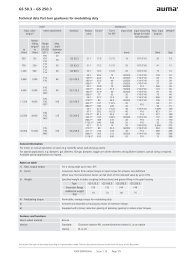
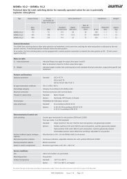
8. Technical data.........................................................................................................................<br />
8.1. Technical data Part-turn gearboxes<br />
9. Spare parts.............................................................................................................................<br />
9.1. Part-turn gearboxes <strong>GS</strong> <strong>50.3</strong> <strong>–</strong> <strong>GS</strong> 125.3<br />
9.2. Part-turn gearboxes <strong>GS</strong> 160.3 <strong>–</strong> <strong>GS</strong> 2<strong>50.3</strong><br />
9.3. Primary reduction gearing for <strong>GS</strong> 100.3 <strong>–</strong> <strong>GS</strong> 125.3 (126:1/160:1/208:1)<br />
9.4. Primary reduction gearing for <strong>GS</strong> 160.3 (218:1/442:1) <strong>GS</strong> 200.3 (214:1/434:1) <strong>GS</strong> 2<strong>50.3</strong><br />
(210:1/411:1)<br />
9.5. Primary reduction gearing for <strong>GS</strong> 200.3 (864:1) <strong>GS</strong> 2<strong>50.3</strong> (848:1)<br />
10. Certificates..............................................................................................................................<br />
10.1. Declaration of Incorporation and EC Declaration of Conformity<br />
Index........................................................................................................................................<br />
Addresses...............................................................................................................................<br />
27<br />
27<br />
27<br />
27<br />
29<br />
29<br />
34<br />
34<br />
36<br />
38<br />
40<br />
42<br />
44<br />
44<br />
47<br />
49<br />
3
Safety instructions<br />
<strong>GS</strong> <strong>50.3</strong> <strong>–</strong> <strong>GS</strong> 2<strong>50.3</strong><br />
1. Safety instructions<br />
1.1. Basic information on safety<br />
Standards/directives<br />
Our products are designed and manufactured in compliance with recognised<br />
standards and directives. This is certified in a Declaration of Incorporation and an<br />
EC Declaration of Conformity.<br />
The end user or the contractor must ensure that all legal requirements, directives,<br />
guidelines, national regulations and recommendations with respect to assembly,<br />
electrical connection, commissioning and operation are met at the place of installation.<br />
Safety instructions/warnings<br />
Qualification of staff<br />
All personnel working with this device must be familiar with the safety and warning<br />
instructions in this manual and observe the instructions given. Safety instructions<br />
and warning signs on the device must be observed to avoid personal injury or property<br />
damage.<br />
Assembly, electrical connection, commissioning, operation, and maintenance must<br />
be carried out exclusively by suitably qualified personnel having been authorised by<br />
the end user or contractor of the plant only.<br />
Prior to working on this product, the staff must have thoroughly read and understood<br />
these instructions and, furthermore, know and observe officially recognised rules<br />
regarding occupational health and safety.<br />
Work performed in potentially explosive atmospheres is subject to special regulations<br />
which have to be observed. The end user or contractor of the plant are responsible<br />
for respect and control of these regulations, standards, and laws.<br />
Commissioning<br />
Operation<br />
Prior to commissioning, it is important to check that all settings meet the requirements<br />
of the application. Incorrect settings might present a danger to the application, e.g.<br />
cause damage to the valve or the installation. The manufacturer will not be held<br />
liable for any consequential damage. Such risk lies entirely with the user.<br />
Prerequisites for safe and smooth operation:<br />
●<br />
●<br />
●<br />
●<br />
●<br />
●<br />
Correct transport, proper storage, mounting and installation, as well as careful<br />
commissioning.<br />
Only operate the device if it is in perfect condition while observing these instructions.<br />
Immediately report any faults and damage and allow for corrective measures.<br />
Observe recognised rules for occupational health and safety.<br />
Observe the national regulations.<br />
During operation, the device warms up and increased surface temperature may<br />
occur. To prevent possible burns, we recommend checking the surface temperature<br />
using an appropriate thermometer and wearing protective gloves, if required,<br />
prior to working on the device.<br />
Protective measures<br />
Maintenance<br />
The end user or the contractor are responsible for implementing required protective<br />
measures on site, such as enclosures, barriers, or personal protective equipment<br />
for the staff.<br />
To ensure safe device operation, the maintenance instructions included in this manual<br />
must be observed.<br />
1.2. Range of application<br />
Any device modification requires prior consent of the manufacturer.<br />
AUMA part-turn gearboxes are designed for the operation of industrial valves, e.g.<br />
butterfly valves and ball valves.<br />
Other applications require explicit (written) confirmation by the manufacturer.<br />
The following applications are not permitted, e.g.:<br />
● Industrial trucks according to EN ISO 3691<br />
4
<strong>GS</strong> <strong>50.3</strong> <strong>–</strong> <strong>GS</strong> 2<strong>50.3</strong><br />
Safety instructions<br />
1.3. Warnings and notes<br />
● Lifting appliances according to EN 14502<br />
● Passenger lifts according to DIN 15306 and 15309<br />
● Service lifts according to EN 81-1/A1<br />
● Escalators<br />
● Continuous duty<br />
● Potentially explosive atmospheres in combination with F21 lubricant type (refer<br />
to name plate)<br />
● Radiation exposed areas in nuclear power plants<br />
No liability can be assumed for inappropriate or unintended use.<br />
Observance of these operation instructions is considered as part of the device's<br />
designated use.<br />
The following warnings draw special attention to safety-relevant procedures in these<br />
operation instructions, each marked by the appropriate signal word (DANGER,<br />
WARNING, CAUTION, NOTICE).<br />
Indicates an imminently hazardous situation with a high level of risk. Failure<br />
to observe this warning could result in death or serious injury.<br />
Indicates a potentially hazardous situation with a medium level of risk. Failure<br />
to observe this warning could result in death or serious injury.<br />
Indicates a potentially hazardous situation with a low level of risk. Failure to<br />
observe this warning may result in minor or moderate injury. May also be used<br />
with property damage.<br />
Potentially hazardous situation. Failure to observe this warning may result in<br />
property damage. Is not used for personal injury.<br />
Arrangement and typographic structure of the warnings<br />
Type of hazard and respective source!<br />
Potential consequence(s) in case of non-observance (option)<br />
→Measures to avoid the danger<br />
→Further measure(s)<br />
Safety alert symbol<br />
warns of a potential personal injury hazard.<br />
1.4. References and symbols<br />
The signal word (here: DANGER) indicates the level of hazard.<br />
The following references and symbols are used in these instructions:<br />
Information<br />
The term Information preceding the text indicates important notes and information.<br />
Symbol for CLOSED (valve closed)<br />
Symbol for OPEN (valve open)<br />
Important information before the next step. This symbol indicates what is required<br />
for the next step or what has to be prepared or observed.<br />
5
Safety instructions<br />
<strong>GS</strong> <strong>50.3</strong> <strong>–</strong> <strong>GS</strong> 2<strong>50.3</strong><br />
< > Reference to other sections<br />
Terms in brackets shown above refer to other sections of the document which provide<br />
further information on this topic.These terms are either listed in the index, a heading<br />
or in the table of contents and may quickly be found.<br />
6
<strong>GS</strong> <strong>50.3</strong> <strong>–</strong> <strong>GS</strong> 2<strong>50.3</strong><br />
Identification<br />
2. Identification<br />
2.1. Name plate<br />
Figure 1: Arrangement of name plates<br />
[1] Gearbox name plate<br />
[2] Additional plate, e.g. KKS plate (Power Plant Classification System)<br />
Description of gearbox name plate<br />
Figure 2: Gearbox name plate (example <strong>GS</strong> 2<strong>50.3</strong>)<br />
[1] Name of manufacturer<br />
[2] Address of manufacturer<br />
[3] Type designation - valve attachment (flange)<br />
[4] Order number<br />
[5] Serial number<br />
[6] Reduction ratio<br />
[7] Factor<br />
[8] Max. valve torque (output torque)<br />
[9] Type of lubricant<br />
[10] Permissible ambient temperature<br />
[11] Explosion-proof version (option)<br />
[12] Can be assigned as an option upon customer request<br />
[13] Enclosure protection<br />
[14] Duty class<br />
[15] Version<br />
[16] Swing angle<br />
[17] Data Matrix code<br />
Type designation<br />
Figure 3: Type designation (example)<br />
1. Type and size of gearbox<br />
7
Identification<br />
<strong>GS</strong> <strong>50.3</strong> <strong>–</strong> <strong>GS</strong> 2<strong>50.3</strong><br />
2. Flange size for valve attachment<br />
Type and size<br />
These instructions apply to the following device types and sizes:<br />
Part-turn actuators type <strong>GS</strong>, sizes <strong>50.3</strong> <strong>–</strong> 2<strong>50.3</strong><br />
Order number<br />
The product can be identified using this number and the technical data as well as<br />
order-related data pertaining to the device can be compiled.<br />
Please always state this number for any product inquiries.<br />
On the Internet at http://www.auma.com, we offer a service allowing authorised<br />
users to download order-related documents such as wiring diagrams and technical<br />
data (both in German and English), inspection certificates and the operation<br />
instructions when entering the order number.<br />
Serial number<br />
Description of the serial number (with the example of 0512CG12345)<br />
05 15 CG12345<br />
05<br />
Positions 1 + 2 : Assembly in week = week 05<br />
15<br />
Positions 3 + 4 : Year of manufacture = 2015<br />
CG12345<br />
Internal number for unambiguous product identification<br />
Reduction ratio<br />
Factor<br />
The reduction ratio within gearing and primary reduction gearing reduces the required<br />
input torques and increases the operating time.<br />
Mechanical conversion factor for actuator size determination:<br />
Input torque = required valve torque (output torque)/factor<br />
Type of lubricant<br />
AUMA abbreviation for type of lubricant used in the gear housing.<br />
Danger of explosion when using inappropriate lubricant in potentially explosive<br />
atmospheres!<br />
→Do not use gearboxes with F21 lubricant in potentially explosive atmospheres.<br />
→Do not mix different lubricants.<br />
Duty class<br />
The duty class specifies the application range of a gearbox relating to the lifetime<br />
requirements.The duty class is only specified for gearboxes in operation mode class<br />
A (OPEN-CLOSE duty).<br />
● Duty class 1: suitable for motor operation, meets the lifetime requirements of<br />
EN 15714-2<br />
● Duty class 2: suitable for motor operation of rarely or infrequently operated<br />
valves which do not exceed 1,000 operations across their total lifetime.<br />
● Duty class 3: suitable (exclusively) for manual operation with approximately<br />
250 operations, in compliance with the specified lifetime requirements in EN<br />
1074-2.<br />
Please refer to separate Technical data for further information on duty classes.<br />
Version<br />
The first letter of the version indicates the position of the worm shaft in relation to<br />
the worm wheel (view on input shaft).<br />
The second letter indicates the direction of rotation at the output drive (view on<br />
housing cover) for clockwise rotation at the input shaft.<br />
8
<strong>GS</strong> <strong>50.3</strong> <strong>–</strong> <strong>GS</strong> 2<strong>50.3</strong><br />
Identification<br />
Versions: Worm shaft position and direction of rotation of output drive <strong>GS</strong> <strong>50.3</strong> <strong>–</strong> <strong>GS</strong> 2<strong>50.3</strong><br />
RR<br />
LL<br />
RL<br />
LR<br />
Description of the four different versions (view on housing cover):<br />
Initials<br />
RR<br />
LL<br />
RL<br />
LR<br />
Direction of rotation at input shaft<br />
Clockwise<br />
Clockwise<br />
Clockwise<br />
Clockwise<br />
Position of worm shaft<br />
Right<br />
Left<br />
Right<br />
Left<br />
Direction of rotation at output drive<br />
Clockwise<br />
Counterclockwise<br />
Counterclockwise<br />
Clockwise<br />
Data Matrix code<br />
When registered as authorised user, you may use the AUMA Support App to scan<br />
the Data Matrix code and directly access the order-related product documents without<br />
having to enter order number of serial number.<br />
Figure 4: Link to the App store:<br />
2.2. Short description<br />
AUMA worm gearboxes are part-turn gearboxes converting a rotary movement at<br />
the input shaft into a part-turn movement at the output drive. The worm gearboxes<br />
are driven either via electric motor (by means of a multi-turn actuator) or manually<br />
(e.g. via a handwheel).The required input torques are reduced due to high reduction<br />
ratios. In standard version, internal end stops limit the swing angle to 100°.<br />
Worm gearboxes are available in different versions to implement various mounting<br />
conditions and rotary directions.<br />
9
Transport, storage and packaging<br />
<strong>GS</strong> <strong>50.3</strong> <strong>–</strong> <strong>GS</strong> 2<strong>50.3</strong><br />
3. Transport, storage and packaging<br />
3.1. Transport<br />
For transport to place of installation, use sturdy packaging.<br />
Transport gearbox and actuator separately.<br />
Hovering load!<br />
Risk of death or serious injury.<br />
→Do NOT stand below hovering load.<br />
→Attach ropes or hooks for the purpose of lifting by hoist only to housing and NOT<br />
to handwheel.<br />
→Check eyebolts for tight seat in housing (verify reach of the screws).<br />
→Observe manufacturer specifications for fixing lifting straps and roundslings.<br />
→Respect total weight of combination (gearbox, primary reduction gearing, actuator).<br />
Table 1:<br />
Weights including grease filling in gear housing<br />
Type<br />
<strong>GS</strong> <strong>50.3</strong><br />
<strong>GS</strong> 63.3<br />
<strong>GS</strong> 80.3<br />
<strong>GS</strong> 100.3 (52:1/107:1)<br />
<strong>GS</strong> 100.3 (126:1/160:1/208:1)<br />
<strong>GS</strong> 125.3 (52:1)<br />
<strong>GS</strong> 125.3 (126:1/160:1/208:1)<br />
<strong>GS</strong> 160.3 (54:1)<br />
<strong>GS</strong> 160.3 (218:1/442:1/880:1)<br />
<strong>GS</strong> 200.3 (53:1)<br />
<strong>GS</strong> 200.3 (214:1/434:1)<br />
<strong>GS</strong> 200.3 (864:1/1 752:1)<br />
<strong>GS</strong> 2<strong>50.3</strong> (52:1)<br />
<strong>GS</strong> 2<strong>50.3</strong> (210:1/411:1)<br />
<strong>GS</strong> 2<strong>50.3</strong> (848:1/1 718:1)<br />
Standard version<br />
Additional weights when mounting extension flanges<br />
F30 for <strong>GS</strong> 125.3<br />
F35 for <strong>GS</strong> 160.3<br />
F40 for <strong>GS</strong> 200.3<br />
F48 for <strong>GS</strong> 2<strong>50.3</strong><br />
Version with base and lever<br />
[kg] 1) [kg]<br />
7<br />
10<br />
12<br />
16<br />
33<br />
39<br />
40<br />
46<br />
80<br />
91<br />
140<br />
160<br />
170<br />
273<br />
296<br />
308<br />
18<br />
33<br />
48<br />
75<br />
23<br />
29<br />
58<br />
64<br />
89<br />
95<br />
139<br />
150<br />
258<br />
278<br />
288<br />
467<br />
490<br />
502<br />
1)<br />
Specified weight includes unmachined coupling<br />
3.2. Storage<br />
Danger of corrosion due to inappropriate storage!<br />
→Store in a well-ventilated, dry room (maximum humidity 70 %).<br />
→Protect against floor dampness by storage on a shelf or on a wooden pallet.<br />
→Cover to protect against dust and dirt.<br />
→Apply suitable corrosion protection agent to uncoated surfaces.<br />
Long-term storage<br />
If the device must be stored for a long period (more than 6 months), the following<br />
points must be observed in addition:<br />
10
<strong>GS</strong> <strong>50.3</strong> <strong>–</strong> <strong>GS</strong> 2<strong>50.3</strong><br />
Transport, storage and packaging<br />
1. Prior to storage:<br />
Protect uncoated surfaces, in particular the output drive parts and mounting<br />
surface, with long-term corrosion protection agent.<br />
2. At an interval of approx. 6 months:<br />
Check for corrosion. If first signs of corrosion show, apply new corrosion protection.<br />
3.3. Packaging<br />
Our products are protected by special packaging for transport when leaving the<br />
factory.The packaging consists of environmentally friendly materials which can easily<br />
be separated and recycled. We use the following packaging materials: wood,<br />
cardboard, paper, and PE foil. For the disposal of the packaging material, we<br />
recommend recycling and collection centres.<br />
11
Assembly<br />
<strong>GS</strong> <strong>50.3</strong> <strong>–</strong> <strong>GS</strong> 2<strong>50.3</strong><br />
4. Assembly<br />
4.1. Mounting position<br />
4.2. Handwheel fitting<br />
The gearboxes described here can be operated without restriction in any mounting<br />
position.<br />
Gearboxes designed for manual operation are supplied with a separate handwheel.<br />
Fitting is performed on site according to the description below.<br />
Figure 5: Handwheel<br />
4.3. Multi-turn actuators for motor operation<br />
[1] Retaining ring for input shaft (partly required)<br />
[2] Gear input shaft<br />
[3] Spacer (partly required)<br />
[4] Handwheel<br />
[5] Spacer (partly required)<br />
[6] Retaining ring<br />
[7] Ball handle<br />
1. For input shafts with keyway: Place retaining ring [1] onto input shaft [2].<br />
2. If required, fit spacer [3].<br />
3. Slip handwheel [4] onto input shaft.<br />
4. If required, fit spacer [5].<br />
5. Secure handwheel [4] using the retaining ring [6] supplied.<br />
6. Fit ball handle [7] to handwheel.<br />
Refer to the operation instructions pertaining to the multi-turn actuator for indications<br />
on how to mount multi-turn actuators to gearboxes.<br />
This chapter supplies basic information and instructions which should be considered<br />
in addition to the operation instructions of the multi-turn actuator.<br />
Screws to actuator<br />
Screws are included in the scope of delivery of the gearbox for mounting AUMA<br />
multi-turn actuators. When mounting other actuators, the screws might be either too<br />
long or too short (insufficient reach of screws).<br />
12
<strong>GS</strong> <strong>50.3</strong> <strong>–</strong> <strong>GS</strong> 2<strong>50.3</strong><br />
Assembly<br />
Risk of actuator falling off in case inappropriate screws used should shear.<br />
Risk of death or serious injury!<br />
→Check length of screws.<br />
→Only use screws with strength class specified herein.<br />
The reach of screws must be sufficient for the internal threads to ensure the<br />
supporting strength of the device and to accept the lateral forces due to the applied<br />
torque.<br />
Screws which are too long could make contact with the housing parts, presenting<br />
the risk that the device performs a radial shift with respect to the gearbox. This can<br />
lead to shearing of the screws.<br />
4.3.1. Mounting positions Multi-turn actuators with part-turn gearboxes<br />
Mounting positions A <strong>–</strong> D for multi-turn actuators with part-turn gearboxes<br />
<strong>GS</strong> versions RR and LL<br />
A<br />
B<br />
C 1)<br />
D<br />
<strong>GS</strong> versions LL and LR<br />
A 1)<br />
B<br />
C<br />
D<br />
1)<br />
Caution: For multi-turn actuators SA/SAR 14.2 and 14.6 with <strong>GS</strong> 125.3, mounting position C is not possible for RR and RL versions;<br />
mounting position A is not possible for LL and LR versions.<br />
4.3.2. Input mounting flange: mount<br />
Please consider possible space constraints on site when selecting the mounting<br />
position.<br />
Mounting positions may easily be changed at a later date.<br />
Up to size <strong>GS</strong> 125.3, the multi-turn actuator-gearbox combination is delivered in the<br />
ordered mounting position. For packing reasons, actuator and gearbox will be<br />
delivered separately from size <strong>GS</strong> 160.3.<br />
An input mounting flange is required for mounting a multi-turn actuator. Depending<br />
on the version, the flange for mounting the multi-turn actuator is already fitted in the<br />
factory.<br />
13
Assembly<br />
<strong>GS</strong> <strong>50.3</strong> <strong>–</strong> <strong>GS</strong> 2<strong>50.3</strong><br />
Table 2:<br />
Suitable input mounting flanges<br />
Gearboxes<br />
<strong>GS</strong> <strong>50.3</strong><br />
<strong>GS</strong> 63.3<br />
<strong>GS</strong> 80.3<br />
<strong>GS</strong> 100.3<br />
<strong>GS</strong> 125.3<br />
<strong>GS</strong> 160.3<br />
<strong>GS</strong> 200.3<br />
<strong>GS</strong> 2<strong>50.3</strong><br />
Reduction ratio<br />
51:1<br />
51:1<br />
82:1<br />
53:1<br />
82:1<br />
52:1<br />
Input shaft<br />
[mm]<br />
16<br />
20<br />
20<br />
20<br />
20<br />
30/(20)<br />
Input mounting flange for mounting multi-turn actuators<br />
EN ISO 5210<br />
F07, F10<br />
F07, F10<br />
F07, F10<br />
F14 (F10)<br />
DIN 3210<br />
G0<br />
G0<br />
G0<br />
G1/2 (G0)<br />
107:1 1) 30<br />
F14 (F10)<br />
G1/2 (G0)<br />
126:1 1) 30<br />
F10<br />
G0<br />
260:1 1) 30<br />
F10<br />
G0<br />
208:1 1) 30<br />
F10<br />
G0<br />
52:1<br />
30<br />
F14<br />
G1/2<br />
126:1 1) 30/(20)<br />
F14 (F10)<br />
(G0)<br />
160:1 1) 30/(20)<br />
F14 (F10)<br />
(G0)<br />
208:1 1) 20<br />
F10, F14<br />
G0<br />
54:1<br />
30<br />
F16 (F14)<br />
G3 (G1/2)<br />
218:1 1) 30/(20)<br />
F14 (F10)<br />
G1/2 (G0)<br />
442:1 1) 20<br />
F10<br />
G0<br />
880:1 1) 20<br />
F10<br />
G0<br />
53:1<br />
40<br />
F25 (F16)<br />
(G3)<br />
1)<br />
30<br />
F14<br />
G1/2<br />
434:1 1) 30/(20)<br />
F14 (F10)<br />
G1/2 (G0)<br />
864:1 1) 20<br />
F14<br />
G0<br />
1,752:1 1) 20<br />
F10<br />
G0<br />
52:1<br />
50<br />
F30 (F25)<br />
<strong>–</strong><br />
210:1 1) 40/(30)<br />
F16 (F14)<br />
G3 (G1/2)<br />
411:1 1) 30<br />
F14<br />
G1/2<br />
848:1 1) 30/(20)<br />
F14 (F10)<br />
G1/2 (G0)<br />
1 718:1 1)<br />
20<br />
F10<br />
G0<br />
1)<br />
Equipped with primary reduction gearing or planetary gearing to reduce input torques.<br />
Assembly steps 1. Clean mounting faces, thoroughly degrease uncoated mounting surfaces.<br />
Figure 6: Mounting example, input mounting flange fitted to gearbox with primary<br />
reduction gearing<br />
[1] Gearbox with primary reduction gearing<br />
[2] Parallel pin<br />
[3] Input mounting flange<br />
2. Mount parallel pin [2].<br />
3. Place input mounting flange [3] and fasten with screws.<br />
14
<strong>GS</strong> <strong>50.3</strong> <strong>–</strong> <strong>GS</strong> 2<strong>50.3</strong><br />
Assembly<br />
4. Fasten screws crosswise to a torque according to table.<br />
Table 3:<br />
Tightening torques for screws (for mounting multi-turn actuator and input mounting flange)<br />
Threads<br />
M8<br />
M10<br />
M12<br />
M16<br />
M20<br />
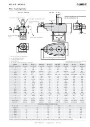
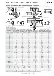
4.4. Gearbox to valve: mount<br />
4.4.1. Output drive for coupling<br />
Tightening torque Nm]<br />
Strength class A2-80<br />
24<br />
48<br />
82<br />
200<br />
392<br />
5. Mount AUMA actuator in compliance with the operation instructions pertaining<br />
to the multi-turn actuator.<br />
The gearbox is mounted to the valve using a coupling (standard) or via lever. Separate<br />
instructions are available for actuator mounting to the valve when equipped with<br />
base and lever.<br />
Application ● For valves with connections according to EN ISO 5211<br />
● For rotating, non-rising valve stem<br />
● Capable of withstanding thrust<br />
Design<br />
Figure 7: Valve attachment via coupling<br />
4.4.1.1. Gearbox with coupling: mount to valve<br />
Information<br />
[1] Gearbox output drive shaft with internal splines<br />
[2] Splined plug-in coupling<br />
[3] Valve shaft (example with keyway and key)<br />
Unbored couplings or couplings with pilot bore must be machined to match the valve<br />
shaft prior to mounting the gearbox to the valve (e.g. with bore and keyway, two-flat<br />
or square bore).<br />
Assemble valve and gearbox in the same end position. As a standard, the gearbox<br />
is supplied in end position CLOSED.<br />
● Recommended mounting position for butterfly valves: End position CLOSED.<br />
● Recommended mounting position for ball valves: End position OPEN.<br />
Assembly steps 1. If required, move gearbox in same end position as valve using the handwheel.<br />
2. Clean mounting faces, thoroughly degrease uncoated mounting surfaces.<br />
3. Apply a small quantity of grease to the valve shaft [2].<br />
15
Assembly<br />
<strong>GS</strong> <strong>50.3</strong> <strong>–</strong> <strong>GS</strong> 2<strong>50.3</strong><br />
4. Fit coupling [1] onto valve shaft [2] and secure against axial slipping by using<br />
a grub screw [3] or a washer and a screw [4]. Thereby, ensure that dimensions<br />
X, Y or L are observed (refer to figure and table ).<br />
Figure 8: Examples: Fit coupling<br />
[1] Coupling<br />
[2] Valve shaft<br />
[3] Grub screw<br />
[4] Screw with washer<br />
Figure 9: Mounting positions for coupling<br />
Table 4:<br />
Dimensions<br />
[mm]<br />
<strong>GS</strong> <strong>50.3</strong><br />
<strong>GS</strong> 63.3<br />
<strong>GS</strong> 80.3<br />
<strong>GS</strong> 100.3<br />
<strong>GS</strong> 125.3<br />
EN ISO 5211<br />
F05<br />
F10<br />
F10<br />
F12<br />
F12<br />
F14<br />
F14<br />
F16<br />
F16<br />
F25<br />
F30 1)<br />
X max.<br />
6<br />
14<br />
7<br />
10<br />
13<br />
23<br />
22<br />
22<br />
17<br />
17<br />
35<br />
Y max.<br />
5<br />
5<br />
18<br />
13<br />
18<br />
5<br />
13<br />
8<br />
35<br />
27<br />
0<br />
L max.<br />
61<br />
61<br />
61<br />
73<br />
76<br />
78<br />
88<br />
123<br />
123<br />
126<br />
126<br />
1)<br />
Extension flange, extended coupling required<br />
16
<strong>GS</strong> <strong>50.3</strong> <strong>–</strong> <strong>GS</strong> 2<strong>50.3</strong><br />
Assembly<br />
Table 5:<br />
Dimensions<br />
[mm]<br />
<strong>GS</strong> 160.3<br />
<strong>GS</strong> 200.3<br />
<strong>GS</strong> 2<strong>50.3</strong><br />
EN ISO 5211<br />
F25<br />
F30 1)<br />
F35<br />
F30<br />
F35<br />
F40 1)<br />
F35<br />
F40<br />
F48 1)<br />
X max.<br />
15<br />
30<br />
30<br />
19<br />
44<br />
44<br />
8<br />
13<br />
20<br />
Y max.<br />
11<br />
0<br />
0<br />
19<br />
0<br />
0<br />
8<br />
0<br />
5<br />
L max.<br />
130<br />
140<br />
130<br />
160<br />
190<br />
160<br />
220<br />
230<br />
220<br />
1)<br />
Extension flange, extended coupling required<br />
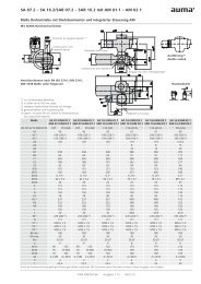
5. Apply non-acidic grease at splines of coupling (e.g. Gleitmo by Fuchs).<br />
6. Experience showed that it is very difficult to fasten screws or nuts of size M30<br />
or larger at defined torques. There is a risk that the worm gearbox might shift<br />
radially with regard to the valve mounting flange. To improve adhesion between<br />
valve and gearbox, we recommend to apply Loctite 243 (or similar adhesive<br />
products) to the mounting faces of screws and nuts from size M30.<br />
7. Fit gearbox. If required, slightly turn gearbox until splines of coupling engage.<br />
Figure 10:<br />
Information<br />
Ensure that the spigot (if provided) fits uniformly in the recess and that the flanges<br />
are in complete contact.<br />
8. If flange bores do not match thread:<br />
8.1 Slightly rotate handwheel until bores line up.<br />
8.2 If required, shift gearbox position by one tooth on the coupling.<br />
9. Fasten gearbox with screws.<br />
Information: We recommend applying liquid thread sealing material to the<br />
screws to avoid contact corrosion.<br />
17
Assembly<br />
<strong>GS</strong> <strong>50.3</strong> <strong>–</strong> <strong>GS</strong> 2<strong>50.3</strong><br />
10. Fasten screws crosswise to a torque according to table.<br />
Table 6:<br />
Tightening torques for screws<br />
Threads<br />
M6<br />
M8<br />
M10<br />
M12<br />
M16<br />
M20<br />
M30<br />
M36<br />
Tightening torque Nm]<br />
Strength class<br />
A2-70/A4-70<br />
8<br />
18<br />
36<br />
61<br />
150<br />
294<br />
564<br />
2,098<br />
A2-80/A4-80<br />
10<br />
24<br />
48<br />
82<br />
200<br />
392<br />
1,422<br />
2,481<br />
18
<strong>GS</strong> <strong>50.3</strong> <strong>–</strong> <strong>GS</strong> 2<strong>50.3</strong><br />
Indications<br />
5. Indications<br />
5.1. Mechanical position indicator/running indication<br />
Mechanical position indicator:<br />
●<br />
●<br />
●<br />
continuously indicates the valve position<br />
(pointer cover [2] follows the valve movement)<br />
indicates whether the actuator is moving (running indication)<br />
indicates that end positions have been reached<br />
(mark on pointer cover [3] points to symbols OPEN [4] or CLOSED [5])<br />
Figure 11: Mechanical position indicator<br />
[1] Housing cover<br />
[2] Pointer cover<br />
[3] Indicator mark<br />
[4] Symbol for position OPEN<br />
[5] Symbol for position CLOSED<br />
19
Commissioning<br />
<strong>GS</strong> <strong>50.3</strong> <strong>–</strong> <strong>GS</strong> 2<strong>50.3</strong><br />
6. Commissioning<br />
6.1. End stops in gearbox<br />
The internal end stops limit the swing angle and protect the valve against overload.<br />
End stop setting is generally performed by the valve manufacturer prior to installing<br />
the valve into the pipework.<br />
Exposed, rotating parts (discs/balls) at the valve!<br />
Pinching and damage at the valve.<br />
→End stops should be set by suitably qualified personnel only.<br />
→Set end stops as to ensure that they are NOT reached during normal operation.<br />
Information<br />
The setting sequence depends on the valve:<br />
● Recommendation for butterfly valves: Set end stop CLOSED first.<br />
● Recommendation for ball valves: Set end stop OPEN first.<br />
Information ● In general, gearboxes with a swing angle > 190° are multi-turn (without end<br />
stops). Consequently, end position setting is not possible. Thus, no protective<br />
function is available for the valve.<br />
● In general, only one end stop (either OPEN or CLOSED) must be set, due to<br />
fact that the swing angle was already set in the factory.<br />
6.1.1. End stop CLOSED: set<br />
Figure 12: End stop (left: up to size 125.3, right: from size 160.3)<br />
[1] Screws<br />
[2] End stop<br />
[3] Housing<br />
1. Remove the four screws [1] at end stop [2].<br />
No overload protection at valve for unfastened end stop!<br />
→In motor operation: Stop travel on time before reaching the valve end position<br />
(consider overrun).<br />
→The last part of the travel must be completed in manual operation mode.<br />
2. Turn valve via handwheel to position CLOSED. Check whether end stop [2]<br />
rotates simultaneously.<br />
→<br />
Otherwise: Turn end stop [2] clockwise to the stop.<br />
20
<strong>GS</strong> <strong>50.3</strong> <strong>–</strong> <strong>GS</strong> 2<strong>50.3</strong><br />
Commissioning<br />
3. With mounted multi-turn actuator (not required for manual operation): Turn end<br />
stop [2] counterclockwise by 1/4 turn.<br />
➥<br />
This ensures that the gearbox end stop cannot be approached during motor<br />
operation if a multi-turn actuator is mounted and that the valve can close tightly<br />
for torque seating.<br />
4. In case the four holes of the end stop [2] do not match the four threaded bores<br />
within the housing [3]: Remove end stop [2] until it disengages from the toothing<br />
and replace in correct position.<br />
5. Fasten screws [1] crosswise with a torque according to table .<br />
Table 7:<br />
Tightening torques for screws at end stop<br />
Gearbox<br />
<strong>GS</strong> <strong>50.3</strong><br />
<strong>GS</strong> <strong>50.3</strong> <strong>–</strong> <strong>GS</strong> 80.3<br />
<strong>GS</strong> 100.3 <strong>–</strong> <strong>GS</strong> 125.3<br />
<strong>GS</strong> 160.3<br />
<strong>GS</strong> 200.3<br />
<strong>GS</strong> 2<strong>50.3</strong><br />
Screws [1]<br />
M6<br />
M8<br />
M12<br />
M10<br />
M12<br />
M16<br />
Tightening torque T A [Nm]<br />
10<br />
24<br />
82<br />
48<br />
82<br />
200<br />
Further settings hereafter:<br />
●<br />
●<br />
If the gearbox is equipped with a pointer cover: Check whether the mark aligns<br />
with the symbol CLOSED. Refer to .<br />
If the gearbox is mounted to a multi-turn actuator, set the seating in end position<br />
CLOSED straight after completion of the current setting: .<br />
6.1.2. End stop OPEN: set<br />
Figure 13: End stop (left: up to size 125.3, right: from size 160.3)<br />
[1] Screws<br />
[2] End stop<br />
[3] Housing<br />
1. Remove the four screws [1] at end stop [2].<br />
No overload protection at valve for unfastened end stop!<br />
→In motor operation: Stop travel on time before reaching the valve end position<br />
(consider overrun).<br />
→The last part of the travel must be in manual operation mode.<br />
2. Turn valve via handwheel in position OPEN. Check whether end stop [2] rotates<br />
simultaneously.<br />
→<br />
Otherwise: Turn end stop [2] counterclockwise to the stop.<br />
21
Commissioning<br />
<strong>GS</strong> <strong>50.3</strong> <strong>–</strong> <strong>GS</strong> 2<strong>50.3</strong><br />
3. With mounted multi-turn actuator (not required for manual operation): Turn end<br />
stop [2] clockwise by 1/4 turn.<br />
➥<br />
This ensures that the gearbox end stop cannot be approached during motor<br />
operation if a multi-turn actuator is mounted and that the valve can close tightly<br />
for torque seating.<br />
4. In case the four holes of the end stop [2] do not match the four threaded bores<br />
within the housing [3]: Remove end stop [2] until it disengages from the toothing<br />
and replace in correct position.<br />
5. Fasten screws [1] crosswise with a torque according to table .<br />
Further settings hereafter:<br />
●<br />
●<br />
If the gearbox is equipped with a pointer cover: Check whether the mark aligns<br />
with the symbol OPEN. Refer to .<br />
If the gearbox is mounted to a multi-turn actuator, set the seating in end position<br />
OPEN straight after completion of the current setting: .<br />
6.2. Seating in end positions via multi-turn actuator<br />
This chapter supplies basic information and notes which should be considered in<br />
addition to the operation instructions of the multi-turn actuator.<br />
●<br />
●<br />
●<br />
●<br />
●<br />
The valve manufacturer has to determine whether the valve is limit or torque<br />
seated.<br />
End position seating must be set in compliance with the operating instructions<br />
pertaining to the multi-turn actuator.<br />
When setting the torque switching within the multi-turn actuator, make sure that<br />
the tripping torque for both directions does not exceed the max. gearbox input<br />
torque (refer to technical data or name plate).<br />
Set the torque switching within the multi-turn actuator to the following value to<br />
prevent damage to the valve:<br />
Tripping torque = valve torque/factor (refer to name plate)<br />
If the swing angle set in the factory for opening and closing the valve is not<br />
sufficient: refer to .<br />
6.2.1. Seating in end position CLOSED: set<br />
1. Move valve to end position CLOSED.<br />
Information: The last part of the travel must be in manual operation mode!<br />
2. For limit seating in end position CLOSED:<br />
2.1 Turn back the valve from the valve end position by an amount equal to<br />
the overrun.<br />
2.2 Set limit switching for the end position CLOSED according to the operation<br />
instructions for the multi-turn actuator.<br />
3. For torque seating in end position CLOSED:<br />
3.1 Gearbox without primary reduction gearing:Turn handwheel in the opposite<br />
direction of the valve end position by approx. 4 <strong>–</strong> 6 turns.<br />
3.2 Gearbox with primary reduction gearing: Turn handwheel in the opposite<br />
direction of the valve end position by approx. 10 <strong>–</strong> 15 turns.<br />
3.3 Check torque switching for end position CLOSED according to operation<br />
instructions for multi-turn actuator and, if necessary, set to required value.<br />
3.4 Set limit switching for signalling end position CLOSED according to operation<br />
instructions for multi-turn actuator.<br />
22
<strong>GS</strong> <strong>50.3</strong> <strong>–</strong> <strong>GS</strong> 2<strong>50.3</strong><br />
Commissioning<br />
6.2.2. Seating in end position OPEN: set<br />
6.3. Swing angle<br />
1. Move valve to end position OPEN.<br />
Information: The last part of the travel must be in manual operation mode!<br />
2. For limit seating in end position OPEN:<br />
2.1 Turn back the valve from the valve end position by an amount equal to<br />
the overrun.<br />
2.2 Set limit switching for end position OPEN according to the operation instructions<br />
for the multi-turn actuator.<br />
3. For torque seating in end position OPEN:<br />
3.1 Gearbox without primary reduction gearing:Turn handwheel in the opposite<br />
direction of the valve end position by approx. 4 <strong>–</strong> 6 turns.<br />
3.2 Gearbox with primary reduction gearing: Turn handwheel in the opposite<br />
direction of the valve end position by approx. 10 <strong>–</strong> 15 turns.<br />
3.3 Check torque switching for end position OPEN according to operation instructions<br />
for multi-turn actuator and, if necessary, set to required value.<br />
3.4 Set limit switching for signalling end position OPEN according to operation<br />
instructions for multi-turn actuator.<br />
The swing angle must only be changed if the swivel range for end stop setting is not<br />
sufficient.<br />
Figure 14: Name plate indicating the swing angle<br />
Versions<br />
Sizes <strong>GS</strong> <strong>50.3</strong> <strong>–</strong> <strong>GS</strong> 125.3 = adjustable swing angle - option<br />
Sizes <strong>GS</strong> 160.3 <strong>–</strong> <strong>GS</strong> 2<strong>50.3</strong> = adjustable swing angle - standard<br />
Accuracy Sizes <strong>GS</strong> <strong>50.3</strong> <strong>–</strong> <strong>GS</strong> 125.3 = 0.6°<br />
Sizes <strong>GS</strong> 160.3 <strong>–</strong> <strong>GS</strong> 2<strong>50.3</strong> = 0.11° up to 0.14°<br />
6.3.1. Swing angle: modify at gearboxes up to size 125.3<br />
The adjustment is made in end position OPEN.<br />
Special tools: Pin drive for spring-type straight pin<br />
●<br />
●<br />
●<br />
for <strong>GS</strong> <strong>50.3</strong> (AUMA art. no. V001.367-Pos.003)<br />
for <strong>GS</strong> 63.3 <strong>–</strong> <strong>GS</strong> 80.3 (AUMA art. no. V001.367-Pos.002)<br />
for <strong>GS</strong> 100.3 <strong>–</strong> <strong>GS</strong> 125.3 (AUMA art. no. V001.367-Pos.001)<br />
23
Commissioning<br />
<strong>GS</strong> <strong>50.3</strong> <strong>–</strong> <strong>GS</strong> 2<strong>50.3</strong><br />
Figure 15: End stop (figure shows size 80.3)<br />
[1] Protective cap<br />
[2] End stop<br />
[3] Spring-type straight pin<br />
[4] End stop nut<br />
[5] Pairs of safety wedge discs (for OPEN and CLOSE)<br />
1. Unscrew protective cap [1] at end stop [2].<br />
2. Remove spring-type straight pin [3] with suitable pin drive (special tool).<br />
3. Swing angle increase:<br />
3.1 Turn end stop nut [4] counterclockwise.<br />
Information: When turning counterclockwise the end stop nut [4] make<br />
sure that the spring-type straight pin [3] can still be tapped within the oblong<br />
hole.<br />
Information<br />
3.2 Move valve manually to the desired end position OPEN.<br />
3.3 Turn end stop nut [4] clockwise until it is tight to the travelling nut.<br />
4. Swing angle reduction:<br />
4.1 Move valve manually to the desired end position OPEN.<br />
4.2 Turn end stop nut [4] clockwise until it is tight to the travelling nut.<br />
Information: Spring-type straight pin [3] must remain completely covered<br />
by end nut [4].<br />
5. Drive in the spring-type straight pin [3] using the appropriate tool.<br />
→ If the slot provided in the end stop nut [4] does not align with the bore of<br />
the worm shaft: Turn end stop nut [4] slighty counterclockwise until the<br />
hole is aligned; then drive in spring-type straight pin [3].<br />
6. Check whether O-ring at protective cap is in good condition, replace if damaged.<br />
7. Fasten protective cap [1].<br />
If the gearbox is mounted to a multi-turn actuator, the limit switching for the end position<br />
OPEN must be set first in compliance with the operation instructions of the<br />
multi-turn actuator. Allow for overrun!<br />
6.3.2. Swing angle: modify at gearboxes from size 160.3<br />
Adjustments are generally made in end position OPEN.<br />
24
<strong>GS</strong> <strong>50.3</strong> <strong>–</strong> <strong>GS</strong> 2<strong>50.3</strong><br />
Commissioning<br />
Figure 16: End stop (figure shows size 200.3)<br />
[1] Screws<br />
[2] Protective cap<br />
[3] Screw with washer<br />
[4] Clamping washer<br />
[5] Setting ring<br />
[6] End stop nut<br />
[7] Travelling nut<br />
[8] Pairs of safety wedge discs (for OPEN and CLOSE)<br />
Information<br />
1. Remove all four screws [1] and pull off protective cap [2].<br />
2. Remove the screw with the washer [3] and clamping washer [4].<br />
3. Pull off setting ring [5].<br />
4. Swing angle increase:<br />
4.1 Turn end stop nut [6] counterclockwise.<br />
4.2 Move valve manually to the desired end position OPEN.<br />
4.3 Turn end stop nut [6] clockwise until it is tight to the travelling nut [7].<br />
5. Swing angle reduction:<br />
5.1 Move valve manually to the desired end position OPEN.<br />
5.2 Turn end stop nut [6] clockwise until it is tight to the travelling nut [7].<br />
6. Fit setting ring [5], secure with clamping washer [4], washer and screw [3].<br />
7. Check whether O-ring at protective cap is in good condition, replace if damaged.<br />
8. Place protective cap [2] and fasten screws [1] crosswise with a torque according<br />
to table .<br />
If the gearbox is mounted to a multi-turn actuator, the limit switching for the end position<br />
OPEN must be set first in compliance with the operation instructions of the<br />
multi-turn actuator.<br />
6.4. Mechanical position indicator: set<br />
End position CLOSED 1. Move valve to end position CLOSED and check setting.<br />
➥ The setting is correct if the mark aligns with the symbol CLOSED.<br />
25
Commissioning<br />
<strong>GS</strong> <strong>50.3</strong> <strong>–</strong> <strong>GS</strong> 2<strong>50.3</strong><br />
2. If the mark position is not correct:<br />
2.1 Slightly loosen screws [1] at pointer cover [two screws up to size 125.3,<br />
four screws as from size 160.3).<br />
2.2 Turn pointer cover to symbol for position CLOSED [5].<br />
2.3 Fasten screws again.<br />
End position OPEN 3. Move valve to end position OPEN and check setting.<br />
➥<br />
The setting is correct if the mark aligns with the symbol OPEN.<br />
26
<strong>GS</strong> <strong>50.3</strong> <strong>–</strong> <strong>GS</strong> 2<strong>50.3</strong><br />
Servicing and maintenance<br />
7. Servicing and maintenance<br />
Damage caused by inappropriate maintenance!<br />
→Servicing and maintenance must be carried out exclusively by suitably qualified<br />
personnel having been authorised by the end user or the contractor of the plant.<br />
Therefore, we recommend contacting our service.<br />
→Only perform servicing and maintenance tasks when the device is switched off.<br />
AUMA<br />
Service & Support<br />
AUMA offer extensive service such as servicing and maintenance as well as customer<br />
product training. For the relevant contact addresses, please refer to <br />
in this document or to the Internet (www.auma.com).<br />
7.1. Preventive measures for servicing and safe operation<br />
●<br />
●<br />
Before commissioning, perform visual inspection for grease leakage and paint<br />
damage (corrosion).<br />
Thoroughly touch up any possible damage to paint. Original paint in small<br />
quantities can be supplied by AUMA.<br />
7.2. Maintenance intervals<br />
Recommendation for plants subject to strong vibration<br />
●<br />
For plants subject to strong vibration, 6 months after commissioning and then<br />
once a year: Check fastening screws between actuator and gearbox/valve for<br />
tightness. If required, fasten screws while applying the tightening torques as<br />
indicated in chapter . For screws sealed and secured with e.g.<br />
thread sealing material, this action is not required.<br />
Recommendation for grease change and seal replacement:<br />
●<br />
●<br />
If rarely operated (typically in buried service), the gearboxes are maintenancefree.<br />
Grease change or re-lubrication is not necessary.<br />
If operated frequently (typically in modulating duty), we recommend changing<br />
both grease and seals after 4 <strong>–</strong> 6 years.<br />
Gearing damage due to using inappropriate grease!<br />
→Only use original lubricants supplied by AUMA.<br />
→Do not mix lubricants.<br />
Instructions for use in potentially explosive atmospheres of categories M2,<br />
2G, 3G, 2D and 3D<br />
●<br />
●<br />
●<br />
●<br />
Imperatively heed the technical data, as well as the ambient temperatures, type<br />
of duty and running times indicated on the name plate are observed.<br />
In potentially explosive atmospheres, in particular where combustible dust is<br />
present, perform visual inspection for deposit of dirt or dust on a regular basis.<br />
Clean devices if required.<br />
The pointer cover is only approved for use in potentially explosive atmospheres<br />
according to ATEX II2G c IIB T4 or T3.<br />
When using mechanical microswitches (option), additionally observe the<br />
mounting and wiring instructions of the manufacturer.<br />
7.3. Disposal and recycling<br />
Our devices have a long lifetime. However, they have to be replaced at one point in<br />
time. The devices have a modular design and may, therefore, easily be separated<br />
and sorted according to materials used, i.e.:<br />
●<br />
●<br />
●<br />
electronic scrap<br />
various metals<br />
plastics<br />
27
Servicing and maintenance<br />
<strong>GS</strong> <strong>50.3</strong> <strong>–</strong> <strong>GS</strong> 2<strong>50.3</strong><br />
● greases and oils<br />
The following generally applies:<br />
●<br />
●<br />
●<br />
Greases and oils are hazardous to water and must not be released into the<br />
environment.<br />
Arrange for controlled waste disposal of the disassembled material or for separate<br />
recycling according to materials.<br />
Observe the national regulations for waste disposal.<br />
28
<strong>GS</strong> <strong>50.3</strong> <strong>–</strong> <strong>GS</strong> 2<strong>50.3</strong><br />
Technical data<br />
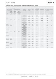
8. Technical data<br />
Information<br />
The following tables include standard and optional features. For detailed information<br />
on the customer-specific version, refer to the order-related data sheet. The technical<br />
data sheet can be downloaded from the Internet in both German and English at http://www.auma.com<br />
(please state the order number).<br />
8.1. Technical data Part-turn gearboxes<br />
General information<br />
For motor or manual operation of valves (e.g. butterfly valves, ball and plug valves).<br />
For special applications, e.g. dampers, gas diverters, flue gas dampers, toggle arm driven diverters and guillotine isolators, special sizing is<br />
required. Special technical data apply for special applications. Available special applications on request.<br />
Features and functions<br />
Worm wheel material<br />
Version<br />
Housing material<br />
Self-locking<br />
End stops<br />
Strength of end stop<br />
Open-close<br />
duty:<br />
Modulating<br />
duty:<br />
Standard:<br />
Option:<br />
Standard:<br />
Option:<br />
Spheroidal cast iron<br />
Bronze<br />
Clockwise rotation RR, counterclockwise rotation LL<br />
RL or LR<br />
Cast iron (GJL-250)<br />
Spheroidal cast iron (GJS-400-15)<br />
The gearboxes are self-locking when at standstill under normal service conditions; strong vibration may<br />
cancel the self-locking effect. While in motion, safe breaking is not guaranteed. If this is required, a<br />
separate brake must be used.<br />
Positive for both end positions by travelling nut, sensitive adjustment<br />
Guaranteed strength of end stop (in Nm) for input side operation<br />
Type<br />
Reduction ratio<br />
[Nm]<br />
<strong>GS</strong> <strong>50.3</strong><br />
51:1<br />
250<br />
<strong>GS</strong> 63.3<br />
51:1<br />
450<br />
<strong>GS</strong> 80.3<br />
53:1<br />
450<br />
52:1<br />
1350<br />
<strong>GS</strong> 100.3<br />
126:1 160:1<br />
625 500<br />
208:1<br />
250<br />
Type<br />
Reduction ratio<br />
[Nm]<br />
52:1<br />
1350<br />
<strong>GS</strong> 125.3<br />
126:1 160:1<br />
625 500<br />
208:1<br />
250<br />
54:1<br />
3200<br />
<strong>GS</strong> 160.3<br />
218:1 442:1<br />
900 450<br />
880:1<br />
250<br />
Type<br />
Reduction ratio<br />
[Nm]<br />
53:1<br />
8000<br />
67:1<br />
250<br />
214:1<br />
2000<br />
<strong>GS</strong> 200.3<br />
434:1<br />
1000<br />
864:1<br />
500<br />
1752:1<br />
250<br />
Type<br />
Reduction ratio<br />
[Nm]<br />
52:1<br />
8000<br />
210:1<br />
2000<br />
<strong>GS</strong> 2<strong>50.3</strong><br />
411:1<br />
1000<br />
848:1<br />
500<br />
1718:1<br />
250<br />
Swing angle <strong>GS</strong> <strong>50.3</strong> <strong>–</strong> <strong>GS</strong> 125.3<br />
Swing angle <strong>GS</strong> 160.3 <strong>–</strong> <strong>GS</strong> 2<strong>50.3</strong><br />
Swing angle at special reduction<br />
ratio <strong>GS</strong> 200.3 - 67:1<br />
Standard:<br />
Options:<br />
Standard:<br />
Options:<br />
Standard:<br />
Options:<br />
Fixed swing angle between 10° and max. 100°; set in the factory to 92° unless ordered<br />
otherwise.<br />
Adjustable in steps of:<br />
10° <strong>–</strong> 35°, 35° <strong>–</strong> 60°, 60° <strong>–</strong> 80°, 80° <strong>–</strong> 100°, 100° <strong>–</strong> 125°, 125° <strong>–</strong> 150°, 150° <strong>–</strong> 170°,170°<br />
<strong>–</strong> 190°<br />
Swing angle > 190°, refer to Technical data <strong>GS</strong> <strong>50.3</strong> <strong>–</strong> <strong>GS</strong> 2<strong>50.3</strong> for modulating duty and<br />
shorter operating times<br />
Adjustable 80° <strong>–</strong> 100°; set in the factory to 92° unless ordered otherwise.<br />
Adjustable in steps of:<br />
0° <strong>–</strong> 20°, 20° <strong>–</strong> 40°, 40° <strong>–</strong> 60°, 60° <strong>–</strong> 80°, 90° <strong>–</strong> 110°, 110° <strong>–</strong> 130°, 130° <strong>–</strong> 150°, 150° <strong>–</strong><br />
170°, 170° <strong>–</strong> 190°<br />
Swing angle > 190°, refer to Technical data <strong>GS</strong> <strong>50.3</strong> <strong>–</strong> <strong>GS</strong> 2<strong>50.3</strong> for modulating duty and<br />
shorter operating times<br />
Adjustable 80° <strong>–</strong> 100°; set in the factory to 92° unless ordered otherwise.<br />
Adjustable in steps of:<br />
0° <strong>–</strong> 20°, 20° <strong>–</strong> 40°, 40° <strong>–</strong> 60°, 60° <strong>–</strong> 80°<br />
Swing angle > 100°, multi-turn version without end stops, <strong>GS</strong>D version, specific sizing<br />
required<br />
29
Technical data<br />
<strong>GS</strong> <strong>50.3</strong> <strong>–</strong> <strong>GS</strong> 2<strong>50.3</strong><br />
Features and functions<br />
Mechanical position indicator<br />
Standard:<br />
Options:<br />
Pointer cover for continuous position indication<br />
● Sealed pointer cover for horizontal outdoor installation (not available for <strong>GS</strong> <strong>50.3</strong>)<br />
●<br />
Protection cover for buried services instead of pointer cover (without mechanical position<br />
indicator)<br />
● Sealed pointer cover with air vent valve, not available for <strong>GS</strong> <strong>50.3</strong><br />
Input shaft<br />
Observe notes on Information sheet Enclosure protection IP68 for part-turn gearboxes<br />
Cylindrical with parallel key according to DIN 6885-1<br />
Operation<br />
Motor operation<br />
●<br />
●<br />
Via electric multi-turn actuator<br />
Input mounting flanges for mounting multi-turn actuators<br />
Type of duty<br />
Maximum permissible input speeds<br />
and operating times<br />
Open-close<br />
duty:<br />
Modulating<br />
duty:<br />
Modulating duty: 215 rpm<br />
Open-close duty:<br />
Short-time duty S2 - 15 min<br />
Class A according to EN 15714-2: OPEN-CLOSE<br />
Class B according to EN 15714-2: Inching/positioning or positioning duty<br />
Intermittent duty S4 - 25 %<br />
Class C according to EN 15714-2: Modulating duty<br />
Type<br />
<strong>GS</strong> 125.3<br />
<strong>GS</strong> 160.3<br />
Reduction ratio<br />
52:1<br />
126:1<br />
160:1<br />
208:1<br />
54:1<br />
218:1<br />
442:1<br />
880:1<br />
Max. permissible<br />
input speed [rpm]<br />
108<br />
216<br />
108<br />
216<br />
Fastest operating<br />
time for 90° [s]<br />
1350<br />
625<br />
500<br />
250<br />
3200<br />
900<br />
450<br />
250<br />
Type<br />
<strong>GS</strong><br />
<strong>50.3</strong><br />
<strong>GS</strong> 63.3<br />
<strong>GS</strong> 80.3<br />
<strong>GS</strong> 100.3<br />
Reduction ratio<br />
51:1<br />
51:1<br />
82:1<br />
53:1<br />
82:1<br />
52:1<br />
107:1<br />
126:1<br />
160:1<br />
208:1<br />
Max. permissible<br />
input speed [rpm]<br />
108<br />
108<br />
108<br />
108<br />
216<br />
Fastest operating<br />
time for 90° [s]<br />
7<br />
7<br />
11<br />
7<br />
11<br />
7<br />
15<br />
9<br />
11<br />
19<br />
Type<br />
<strong>GS</strong> 200.3<br />
<strong>GS</strong> 2<strong>50.3</strong><br />
Reduction ratio<br />
53:1<br />
214:1<br />
434:1<br />
864:1<br />
1752:1<br />
52:1<br />
210:1<br />
411:1<br />
848:1<br />
1718:1<br />
Max. permissible input<br />
speed [rpm]<br />
108<br />
216<br />
108<br />
216<br />
Fastest operating<br />
time for 90° [s]<br />
7<br />
15<br />
30<br />
60<br />
122<br />
7<br />
15<br />
29<br />
59<br />
119<br />
Due to gear tooth geometry and the material characteristics of bronze, worm gearboxes with a worm<br />
wheel made of bronze can transmit lower torques<br />
Calculation of operating time for a 90° swivel movement<br />
Calculation of the operating time for a swivel movement [°]:<br />
30
<strong>GS</strong> <strong>50.3</strong> <strong>–</strong> <strong>GS</strong> 2<strong>50.3</strong><br />
Technical data<br />
Operation<br />
Manual operation<br />
Standard:<br />
●<br />
Handwheel made of aluminium with electrophoretic coating<br />
●<br />
Handwheel with ball handle<br />
Option:<br />
●<br />
Handwheel made of GJL-200 with electrophoretic coating and painting<br />
●<br />
Handwheel lockable<br />
●<br />
WSH for signalling position and end positions<br />
Available handwheel diameters according to EN 12570, selection according to output torque:<br />
Type<br />
Reduction ratio<br />
Handwheel Ø [mm]<br />
<strong>GS</strong><br />
<strong>50.3</strong><br />
51:1<br />
160<br />
200<br />
250<br />
<strong>GS</strong><br />
63.3<br />
51:1<br />
250<br />
315<br />
<strong>GS</strong><br />
80.3<br />
53:1<br />
315<br />
400<br />
52:1<br />
400<br />
500<br />
<strong>GS</strong> 100.3<br />
126:1<br />
315<br />
400<br />
160:1<br />
208:1<br />
250<br />
315<br />
52:1<br />
500<br />
630<br />
800<br />
<strong>GS</strong> 125.3<br />
126:1<br />
400<br />
500<br />
160:1<br />
208:1<br />
315<br />
400<br />
Type<br />
Reduction ratio<br />
Handwheel Ø [mm]<br />
54:1<br />
630<br />
800<br />
<strong>GS</strong> 160.3<br />
218:1 442:1<br />
400 315<br />
880:1<br />
250<br />
53:1<br />
<strong>–</strong><br />
67:1<br />
800<br />
<strong>GS</strong> 200.3<br />
214:1<br />
500<br />
630<br />
434:1<br />
400<br />
864:1<br />
315<br />
1752:1<br />
250<br />
Type<br />
Reduction ratio<br />
Handwheel Ø [mm]<br />
52:1<br />
<strong>–</strong><br />
210:1<br />
800<br />
<strong>GS</strong> 2<strong>50.3</strong><br />
411:1<br />
500<br />
630<br />
848:1<br />
400<br />
1718:1<br />
315<br />
Deflection of the input shaft<br />
90° deflection of the input shaft<br />
Combination with GK bevel gearbox directly mounted on <strong>GS</strong> or on planetary stage possible, refer to Mounting positions Part-turn gearboxes<br />
with multi-turn actuators<br />
Version with base and lever<br />
Not suitable for load class 3.<br />
Base<br />
Lever<br />
Ball joints<br />
Mechanical position indicator<br />
Made of spheroidal cast iron; for mounting to base, 4 holes for fastening screws are available.<br />
Made of spheroidal cast iron; with 2 or 3 bores for fixing lever arrangement. Considering the environmental<br />
conditions, the lever may be mounted to the output shaft in any desired position.<br />
Two ball joints matching the lever, as an option including lock nuts and 2 welding nuts; suitable for pipe<br />
according to dimension sheet.<br />
Standard:<br />
Option:<br />
No position indicator (protection cover)<br />
Pointer cover instead of protection cover for continuous position indication<br />
31
Technical data<br />
<strong>GS</strong> <strong>50.3</strong> <strong>–</strong> <strong>GS</strong> 2<strong>50.3</strong><br />
Valve attachment<br />
Valve attachment<br />
Spigot<br />
Bore for locating pins (option)<br />
Dimensions according to EN ISO 5211: The maximum torques of mounting flanges according to EN<br />
ISO 5211 are to be met.<br />
Flanges with spigot, recess or plane flanges are available. Up to <strong>GS</strong> 125.3, spigots are implemented by<br />
means of spigot rings. From <strong>GS</strong> 160.3 to <strong>GS</strong> 2<strong>50.3</strong>, recesses and spigots are directly integrated into<br />
the housing.<br />
Two bores for locating pins shifted by 180°. The locating pins are not included in the scope of delivery.<br />
Type<br />
Flange according to<br />
EN ISO 5211<br />
Housing material<br />
<strong>GS</strong> 80.3<br />
F12 F14<br />
GJS GJS<br />
<strong>GS</strong> 100.3<br />
F14 F16<br />
GJS GJS<br />
F16<br />
GJL<br />
<strong>GS</strong> 125.3<br />
F25<br />
GJL<br />
F30<br />
GJL<br />
F25<br />
GJL<br />
<strong>GS</strong> 160.3<br />
F30<br />
GJL<br />
F35<br />
GJL<br />
Type<br />
Flange according to<br />
EN ISO 5211<br />
Housing material<br />
F30<br />
GJL<br />
<strong>GS</strong> 200.3<br />
F35<br />
GJL<br />
F40<br />
GJL<br />
F35<br />
GJL<br />
<strong>GS</strong> 2<strong>50.3</strong><br />
F40<br />
GJL<br />
F48<br />
GJL<br />
Splined coupling for connection to<br />
the valve shaft<br />
Refer to dimension drawing U4.4135. Further pitch circle diameters and bore depths for locating pins<br />
on request<br />
Standard:<br />
● Without bore or pilot bore from <strong>GS</strong> 160.3<br />
●<br />
Worm gearbox can be mounted on coupling<br />
Options:<br />
Finish machining with bore and keyway, square bore or two-flat with grub screw for secure<br />
fixing to valve shaft.<br />
Service conditions<br />
Mounting position<br />
Ambient temperature<br />
Enclosure protection according to<br />
EN 60529<br />
Corrosion protection<br />
Finish coating<br />
Colour<br />
Any position<br />
II2D c<br />
T130°C<br />
Standard:<br />
Options:<br />
Standard:<br />
Options:<br />
KN<br />
KS<br />
KX<br />
<strong>–</strong>40 °C to +80 °C<br />
<strong>–</strong>60 °C to +60 °C<br />
0 °C to +120 °C<br />
Note: When using mechanical microswitches, the temperature ranges indicated here are<br />
reduced to <strong>–</strong>30 °C up to max. +90 °C.<br />
IP68, dust-tight and water-tight up to max. 8 m head of water<br />
IP68-20, dust-tight and water-tight up to max. 20 m head of water<br />
<strong>GS</strong> <strong>50.3</strong> <strong>–</strong> <strong>GS</strong> 80.3: KS<br />
<strong>GS</strong> 100.3 <strong>–</strong> <strong>GS</strong> 2<strong>50.3</strong>: KN<br />
<strong>GS</strong> <strong>50.3</strong> <strong>–</strong> <strong>GS</strong> 80.3: KX<br />
<strong>GS</strong> 100.3 <strong>–</strong> <strong>GS</strong> 2<strong>50.3</strong>: KS/KX<br />
Suitable for installation in industrial units, in water or power plants with a low pollutant<br />
concentration<br />
Suitable for use in areas with high salinity, almost permanent condensation, and high<br />
pollution.<br />
Suitable for use in areas with extremely high salinity, permanent condensation, and high<br />
pollution.<br />
<strong>GS</strong> <strong>50.3</strong> <strong>–</strong> <strong>GS</strong> 80.3: Powder coating<br />
<strong>GS</strong> 100.3 <strong>–</strong> <strong>GS</strong> 2<strong>50.3</strong>: Two-component iron-mica combination<br />
Option:<br />
AUMA silver-grey (similar to RAL 7037)<br />
Available colours on request<br />
32
<strong>GS</strong> <strong>50.3</strong> <strong>–</strong> <strong>GS</strong> 2<strong>50.3</strong><br />
Technical data<br />
Service conditions<br />
AUMA load profile<br />
AUMA worm gearboxes meet or even exceed the lifetime requirements of EN 15714-2.<br />
For open-close duty with worm wheel made of spheroidal cast iron:<br />
Lifetime for motor operation in accordance<br />
with AUMA load profile<br />
For modulating duty with worm wheel made of bronze:<br />
A start consists of one movement of minimum 1 % in both directions at a load of 35 % of the maximum<br />
valve torque (modulating torque).<br />
For open-close duty with worm wheel made of spheroidal cast iron:<br />
Duty class 1: Lifetime for 90° swivel movement Meets the lifetime requirement of EN 15714-2<br />
Gearbox size<br />
Number of cycles<br />
for max. torque<br />
<strong>GS</strong> <strong>50.3</strong>/<strong>GS</strong> 63.3<br />
10,000<br />
<strong>GS</strong> 80.3/<strong>GS</strong>100.3<br />
5,000<br />
<strong>GS</strong> 125.3 <strong>–</strong> <strong>GS</strong><br />
200.3<br />
2,500<br />
<strong>GS</strong> 2<strong>50.3</strong><br />
1,200<br />
Duty class 2: Lifetime for 90° swivel movement for valves which are infrquently operated.<br />
Gearbox size<br />
Number of cycles<br />
for max. torque<br />
<strong>GS</strong> <strong>50.3</strong>/<strong>GS</strong> 63.3<br />
<strong>GS</strong> 80.3/<strong>GS</strong>100.3<br />
1,000<br />
<strong>GS</strong> 125.3 <strong>–</strong> <strong>GS</strong><br />
200.3<br />
<strong>GS</strong> 2<strong>50.3</strong><br />
Lifetime for manual operation<br />
Lifetime for larger swing angles on request<br />
For modulating duty with worm wheel made of bronze:<br />
1.2 million modulating steps<br />
Duty class 3: Meets the lifetime requirement of EN 1074-2<br />
Further information<br />
EU Directives<br />
ATEX Directive: (94/9/EC)<br />
Machinery Directive: (2006/42/EC)<br />
33
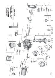
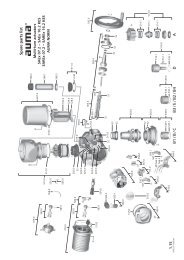
Spare parts<br />
<strong>GS</strong> <strong>50.3</strong> <strong>–</strong> <strong>GS</strong> 2<strong>50.3</strong><br />
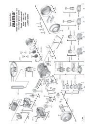
9. Spare parts<br />
9.1. Part-turn gearboxes <strong>GS</strong> <strong>50.3</strong> <strong>–</strong> <strong>GS</strong> 125.3<br />
34
<strong>GS</strong> <strong>50.3</strong> <strong>–</strong> <strong>GS</strong> 2<strong>50.3</strong><br />
Spare parts<br />
Please state device type and our order number (see name plate) when ordering spare parts. Only original AUMA spare parts should be used.<br />
Failure to use original spare parts voids the warranty and exempts AUMA from any liability. Delivered spare parts may slightly vary from the<br />
representation in these instructions.<br />
Ref. no.<br />
512.0<br />
517.0<br />
518.0<br />
519.1<br />
520.0<br />
521.0<br />
521.1<br />
521.12<br />
522.0<br />
523.0<br />
524.0<br />
525.0<br />
526.0<br />
527.0<br />
534.0<br />
538.0<br />
595.0<br />
619.1<br />
S1<br />
Designation<br />
Input mounting flange<br />
Housing<br />
Housing cover<br />
Worm wheel<br />
Worm shaft<br />
Travelling nut with two pairs of safety wedge discs<br />
Travelling nut<br />
Pair of safety wedge discs<br />
Bearing cover<br />
End stop<br />
Pointer cover<br />
Coupling<br />
End stop nut<br />
Protection cover<br />
Drive shaft<br />
Bearing cover with drive shaft<br />
Screw kit for manual gearbox<br />
Extension flange<br />
Seal kit<br />
Type<br />
Sub-assembly<br />
Sub-assembly<br />
Sub-assembly<br />
Sub-assembly<br />
Sub-assembly<br />
Sub-assembly<br />
Sub-assembly<br />
Sub-assembly<br />
Sub-assembly<br />
Sub-assembly<br />
Sub-assembly<br />
Sub-assembly<br />
Sub-assembly<br />
Sub-assembly<br />
Sub-assembly<br />
Set<br />
35
Spare parts<br />
<strong>GS</strong> <strong>50.3</strong> <strong>–</strong> <strong>GS</strong> 2<strong>50.3</strong><br />
9.2. Part-turn gearboxes <strong>GS</strong> 160.3 <strong>–</strong> <strong>GS</strong> 2<strong>50.3</strong><br />
36
<strong>GS</strong> <strong>50.3</strong> <strong>–</strong> <strong>GS</strong> 2<strong>50.3</strong><br />
Spare parts<br />
Please state device type and our order number (see name plate) when ordering spare parts. Only original AUMA spare parts should be used.<br />
Failure to use original spare parts voids the warranty and exempts AUMA from any liability. Delivered spare parts may slightly vary from the<br />
representation in these instructions.<br />
Ref. no.<br />
512.0<br />
513.1<br />
517.0<br />
518.0<br />
519.1<br />
520.0<br />
521.0<br />
521.1<br />
521.2<br />
522.0<br />
523.0<br />
524.0<br />
525.0<br />
526.0<br />
527.0<br />
534.0<br />
536.0<br />
537.0<br />
538.0<br />
595.0<br />
619.1<br />
S1<br />
Designation<br />
Input mounting flange<br />
Grub screw<br />
Housing<br />
Housing cover<br />
Worm wheel<br />
Worm shaft<br />
Travelling nut with two pairs of safety wedge discs<br />
Travelling nut<br />
Pair of safety wedge discs<br />
Bearing cover<br />
End stop<br />
Pointer cover<br />
Coupling<br />
End stop nut<br />
Protection cover<br />
Drive shaft<br />
Protective cap<br />
Lock nut<br />
Bearing cover with drive shaft<br />
Screw kit for manual gearbox<br />
Extension flange<br />
Seal kit<br />
Type<br />
Sub-assembly<br />
Sub-assembly<br />
Sub-assembly<br />
Sub-assembly<br />
Sub-assembly<br />
Sub-assembly<br />
Sub-assembly<br />
Sub-assembly<br />
Sub-assembly<br />
Sub-assembly<br />
Sub-assembly<br />
Sub-assembly<br />
Sub-assembly<br />
Sub-assembly<br />
Sub-assembly<br />
Sub-assembly<br />
Sub-assembly<br />
Set<br />
37
Spare parts<br />
<strong>GS</strong> <strong>50.3</strong> <strong>–</strong> <strong>GS</strong> 2<strong>50.3</strong><br />
9.3. Primary reduction gearing for <strong>GS</strong> 100.3 <strong>–</strong> <strong>GS</strong> 125.3 (126:1/160:1/208:1)<br />
38
<strong>GS</strong> <strong>50.3</strong> <strong>–</strong> <strong>GS</strong> 2<strong>50.3</strong><br />
Spare parts<br />
Please state device type and our order number (see name plate) when ordering spare parts. Only original AUMA spare parts should be used.<br />
Failure to use original spare parts voids the warranty and exempts AUMA from any liability. Delivered spare parts may slightly vary from the<br />
representation in these instructions.<br />
Ref. no.<br />
003.0<br />
019.0<br />
020.0<br />
021.0<br />
022.0<br />
045.0<br />
512.0<br />
595.0<br />
S1<br />
Designation<br />
Housing cover with drive shaft<br />
Housing<br />
Housing cover<br />
Drive shaft<br />
Planet carrier<br />
Internal geared wheel<br />
Input mounting flange<br />
Screw kit for manual gearbox<br />
Seal kit<br />
Type<br />
Sub-assembly<br />
Sub-assembly<br />
Sub-assembly<br />
Sub-assembly<br />
Sub-assembly<br />
Sub-assembly<br />
Sub-assembly<br />
Sub-assembly<br />
Set<br />
39
Spare parts<br />
<strong>GS</strong> <strong>50.3</strong> <strong>–</strong> <strong>GS</strong> 2<strong>50.3</strong><br />
9.4. Primary reduction gearing for <strong>GS</strong> 160.3 (218:1/442:1) <strong>GS</strong> 200.3 (214:1/434:1) <strong>GS</strong> 2<strong>50.3</strong> (210:1/411:1)<br />
40
<strong>GS</strong> <strong>50.3</strong> <strong>–</strong> <strong>GS</strong> 2<strong>50.3</strong><br />
Spare parts<br />
Please state device type and our order number (see name plate) when ordering spare parts. Only original AUMA spare parts should be used.<br />
Failure to use original spare parts voids the warranty and exempts AUMA from any liability. Delivered spare parts may slightly vary from the<br />
representation in these instructions.<br />
Ref. no.<br />
001.0<br />
002.0<br />
003.0<br />
006.0<br />
007.0<br />
008.0<br />
512.0<br />
534.0<br />
588.1<br />
595.0<br />
S1<br />
Designation<br />
Housing<br />
Housing cover<br />
Housing cover with drive shaft<br />
Planetary gearing first stage (<strong>GS</strong> 160.3)<br />
Planetary gearing first stage (<strong>GS</strong> 200.3)<br />
Planetary gearing first stage (<strong>GS</strong> 2<strong>50.3</strong>)<br />
Input mounting flange<br />
Drive shaft<br />
Blanking plugs<br />
Screw kit for manual gearbox<br />
Seal kit<br />
Type<br />
Sub-assembly<br />
Sub-assembly<br />
Sub-assembly<br />
Sub-assembly<br />
Sub-assembly<br />
Sub-assembly<br />
Sub-assembly<br />
Sub-assembly<br />
Sub-assembly<br />
Set<br />
41
Spare parts<br />
<strong>GS</strong> <strong>50.3</strong> <strong>–</strong> <strong>GS</strong> 2<strong>50.3</strong><br />
9.5. Primary reduction gearing for <strong>GS</strong> 200.3 (864:1) <strong>GS</strong> 2<strong>50.3</strong> (848:1)<br />
42
<strong>GS</strong> <strong>50.3</strong> <strong>–</strong> <strong>GS</strong> 2<strong>50.3</strong><br />
Spare parts<br />
Please state device type and our order number (see name plate) when ordering spare parts. Only original AUMA spare parts should be used.<br />
Failure to use original spare parts voids the warranty and exempts AUMA from any liability. Delivered spare parts may slightly vary from the<br />
representation in these instructions.<br />
Ref. no.<br />
001.0<br />
002.0<br />
003.0<br />
006.0<br />
007.0<br />
008.0<br />
010.0<br />
011.1<br />
512.0<br />
534.0<br />
588.1<br />
595.0<br />
S1<br />
Designation<br />
Housing<br />
Housing cover<br />
Housing cover with drive shaft<br />
Planetary gearing first stage<br />
Planetary gear second stage (<strong>GS</strong> 200.3)<br />
Planetary gear second stage (<strong>GS</strong> 2<strong>50.3</strong>)<br />
Intermediate housing<br />
Pinion<br />
Input mounting flange<br />
Drive shaft<br />
Blanking plugs<br />
Screw kit for manual gearbox<br />
Seal kit<br />
Type<br />
Sub-assembly<br />
Sub-assembly<br />
Sub-assembly<br />
Sub-assembly<br />
Sub-assembly<br />
Sub-assembly<br />
Sub-assembly<br />
Sub-assembly<br />
Sub-assembly<br />
Sub-assembly<br />
Set<br />
43
Certificates<br />
<strong>GS</strong> <strong>50.3</strong> <strong>–</strong> <strong>GS</strong> 2<strong>50.3</strong><br />
10. Certificates<br />
10.1. Declaration of Incorporation and EC Declaration of Conformity<br />
44
<strong>GS</strong> <strong>50.3</strong> <strong>–</strong> <strong>GS</strong> 2<strong>50.3</strong><br />
45
46<br />
<strong>GS</strong> <strong>50.3</strong> <strong>–</strong> <strong>GS</strong> 2<strong>50.3</strong>
<strong>GS</strong> <strong>50.3</strong> <strong>–</strong> <strong>GS</strong> 2<strong>50.3</strong><br />
Index<br />
Index<br />
A<br />
Ambient temperature 7 , 32<br />
Applications 4<br />
Assembly 12<br />
B<br />
Base 31<br />
C<br />
Certificates 44<br />
Commissioning 4 , 20<br />
Corrosion protection 10 , 32<br />
Coupling 15 , 32<br />
D<br />
Data Matrix code 9<br />
Declaration of Incorporation 44<br />
Deflection 31<br />
Device type 7<br />
Directives 4<br />
Disposal 27<br />
Duty class 7 , 8<br />
E<br />
EC Declaration of Conformity 44<br />
Enclosure protection 7 , 32<br />
End stops 20 , 29<br />
Explosion protection version 7<br />
F<br />
Factor 7 , 8<br />
Features and functions 30<br />
Flange 7<br />
Flanges 13<br />
H<br />
Handwheel 12<br />
Housing material 29<br />
I<br />
Identification 7<br />
Indications 19<br />
Input mounting flanges 13<br />
Input shaft 30<br />
Input speeds 30<br />
Inspection certificate 8<br />
L<br />
Lever 31<br />
Lifetime 33<br />
Load profile 33<br />
Locating pins 32<br />
M<br />
Maintenance 4 , 27<br />
Maintenance intervals 27<br />
Manual operation 31<br />
Mechanical position indicator 19 , 25 , 30<br />
Motor operation 30<br />
Mounting position 12 , 32<br />
Multi-turn actuators for motor<br />
12<br />
operation<br />
N<br />
Name plate 7<br />
O<br />
Operating times 30<br />
Operation 4 , 31<br />
Order number 7 , 8<br />
Output torque 7<br />
P<br />
Packaging 11<br />
Pointer cover 19 , 25<br />
Position indicator 25<br />
Protective measures 4<br />
Q<br />
Qualification of staff 4<br />
R<br />
Range of application 4<br />
Recycling 27<br />
Reduction ratio 7 , 8<br />
Replacing the seals 27<br />
Running indication 19<br />
S<br />
Safety instructions 4<br />
Safety instructions/warnings 4<br />
Screws to actuator 12<br />
Seating 22<br />
Self-locking 29<br />
Serial number 7 , 8<br />
Service 27<br />
Service conditions 33<br />
Servicing 27<br />
Size 7<br />
Spare parts 34<br />
Spigot 32<br />
Standards 4<br />
Storage 10<br />
Strength of end stop 29<br />
Support 27<br />
Support App 9 , 9<br />
Swing angle 7 , 23 , 29<br />
47
Index<br />
<strong>GS</strong> <strong>50.3</strong> <strong>–</strong> <strong>GS</strong> 2<strong>50.3</strong><br />
T<br />
Technical data 29<br />
Transport 10<br />
Type (device type) 7<br />
Type designation 7<br />
Type of duty 30<br />
Type of lubricant 7 , 8<br />
V<br />
Valve attachment 7 , 32<br />
Valve torque 7<br />
Version 7 , 8 , 29<br />
W<br />
Worm wheel material 29<br />
Y<br />
Year of manufacture 8<br />
Year of production 8<br />
48
AUMA worldwide<br />
Europe<br />
AUMA Riester GmbH & Co. KG<br />
Plant Müllheim<br />
DE 79373 Müllheim<br />
Tel +49 7631 809 - 0<br />
riester@auma.com<br />
www.auma.com<br />
Plant Ostfildern-Nellingen<br />
DE 73747 Ostfildern<br />
Tel +49 711 34803 - 0<br />
riester@wof.auma.com<br />
Service-Center Bayern<br />
DE 85386 Eching<br />
Tel +49 81 65 9017- 0<br />
Riester@scb.auma.com<br />
Service-Center Köln<br />
DE 50858 Köln<br />
Tel +49 2234 2037 - 900<br />
Service@sck.auma.com<br />
Service-Center Magdeburg<br />
DE 39167 Niederndodeleben<br />
Tel +49 39204 759 - 0<br />
Service@scm.auma.com<br />
AUMA-Armaturenantriebe Ges.m.b.H.<br />
AT 2512 Tribuswinkel<br />
Tel +43 2252 82540<br />
office@auma.at<br />
www.auma.at<br />
AUMA BENELUX B.V. B. A.<br />
BE 8800 Roeselare<br />
Tel +32 51 24 24 80<br />
office@auma.be<br />
www.auma.nl<br />
ProStream Group Ltd.<br />
BG 1632 Sofia<br />
Tel +359 2 9179-337<br />
valtchev@prostream.bg<br />
www.prostream.bg<br />
OOO “Dunkan-Privod”<br />
BY 220004 Minsk<br />
Tel +375 29 6945574<br />
belarus@auma.ru<br />
www.zatvor.by<br />
AUMA (Schweiz) AG<br />
CH 8965 Berikon<br />
Tel +41 566 400945<br />
RettichP.ch@auma.com<br />
AUMA Servopohony spol. s.r.o.<br />
CZ 250 01 Brandýs n.L.-St.Boleslav<br />
Tel +420 326 396 993<br />
auma-s@auma.cz<br />
www.auma.cz<br />
GRØNBECH & SØNNER A/S<br />
DK 2450 København SV<br />
Tel +45 33 26 63 00<br />
<strong>GS</strong>@g-s.dk<br />
www.g-s.dk<br />
IBEROPLAN S.A.<br />
ES 28027 Madrid<br />
Tel +34 91 3717130<br />
iberoplan@iberoplan.com<br />
AUMA Finland Oy<br />
FI 02230 Espoo<br />
Tel +358 9 5840 22<br />
auma@auma.fi<br />
www.auma.fi<br />
AUMA France S.A.R.L.<br />
FR 95157 Taverny Cedex<br />
Tel +33 1 39327272<br />
info@auma.fr<br />
www.auma.fr<br />
AUMA ACTUATORS Ltd.<br />
GB Clevedon, North Somerset BS21 6TH<br />
Tel +44 1275 871141<br />
mail@auma.co.uk<br />
www.auma.co.uk<br />
D. G. Bellos & Co. O.E.<br />
GR 13673 Acharnai, Athens<br />
Tel +30 210 2409485<br />
info@dgbellos.gr<br />
APIS CENTAR d. o. o.<br />
HR 10437 Bestovje<br />
Tel +385 1 6531 485<br />
auma@apis-centar.com<br />
www.apis-centar.com<br />
Fabo Kereskedelmi és Szolgáltató Kft.<br />
HU 8800 Nagykanizsa<br />
Tel +36 93/324-666<br />
auma@fabo.hu<br />
www.fabo.hu<br />
Falkinn HF<br />
IS 108 Reykjavik<br />
Tel +00354 540 7000<br />
os@falkinn.is<br />
www.falkinn.is<br />
AUMA ITALIANA S.r.l. a socio unico<br />
IT 20023 Cerro Maggiore (MI)<br />
Tel +39 0331 51351<br />
info@auma.it<br />
www.auma.it<br />
AUMA BENELUX B.V.<br />
LU Leiden (NL)<br />
Tel +31 71 581 40 40<br />
office@auma.nl<br />
NB Engineering Services<br />
MT ZBR 08 Zabbar<br />
Tel + 356 2169 2647<br />
nikibel@onvol.net<br />
AUMA BENELUX B.V.<br />
NL 2314 XT Leiden<br />
Tel +31 71 581 40 40<br />
office@auma.nl<br />
www.auma.nl<br />
SIGUM A. S.<br />
NO 1338 Sandvika<br />
Tel +47 67572600<br />
post@sifag.no<br />
AUMA Polska Sp. z o.o.<br />
PL 41-219 Sosnowiec<br />
Tel +48 32 783 52 00<br />
biuro@auma.com.pl<br />
www.auma.com.pl<br />
AUMA-LUSA Representative Office, Lda.<br />
PT 2730-033 Barcarena<br />
Tel +351 211 307 100<br />
geral@aumalusa.pt<br />
SAUTECH<br />
RO 011783 Bucuresti<br />
Tel +40 372 303982<br />
office@sautech.ro<br />
OOO PRIWODY AUMA<br />
RU 141402 Khimki, Moscow region<br />
Tel +7 495 221 64 28<br />
aumarussia@auma.ru<br />
www.auma.ru<br />
OOO PRIWODY AUMA<br />
RU 125362 Moscow<br />
Tel +7 495 787 78 21<br />
aumarussia@auma.ru<br />
www.auma.ru<br />
ERICHS ARMATUR AB<br />
SE 20039 Malmö<br />
Tel +46 40 311550<br />
info@erichsarmatur.se<br />
www.erichsarmatur.se<br />
ELSO-b, s.r.o.<br />
SK 94901 Nitra<br />
Tel +421 905/336-926<br />
elsob@stonline.sk<br />
www.elsob.sk<br />
Auma Endüstri Kontrol Sistemleri Limited<br />
Sirketi<br />
TR 06810 Ankara<br />
Tel +90 312 217 32 88<br />
info@auma.com.tr<br />
AUMA Technology Automations Ltd<br />
UA 02099 Kiev<br />
Tel +38 044 586-53-03<br />
auma-tech@aumatech.com.ua<br />
Africa<br />
Solution Technique Contrôle Commande<br />
DZ Bir Mourad Rais, Algiers<br />
Tel +213 21 56 42 09/18<br />
stcco@wissal.dz<br />
A.T.E.C.<br />
EG Cairo<br />
Tel +20 2 23599680 - 23590861<br />
contactus@atec-eg.com<br />
SAMIREG<br />
MA 203000 Casablanca<br />
Tel +212 5 22 40 09 65<br />
samireg@menara.ma<br />
MANZ INCORPORATED LTD.<br />
NG Port Harcourt<br />
Tel +234-84-462741<br />
mail@manzincorporated.com<br />
www.manzincorporated.com<br />
49
AUMA worldwide<br />
AUMA South Africa (Pty) Ltd.<br />
ZA 1560 Springs<br />
Tel +27 11 3632880<br />
aumasa@mweb.co.za<br />
America<br />
AUMA Argentina Rep.Office<br />
AR Buenos Aires<br />
Tel +54 11 4737 9026<br />
contacto@aumaargentina.com.ar<br />
AUMA Automação do Brazil ltda.<br />
BR Sao Paulo<br />
Tel +55 11 4612-3477<br />
contato@auma-br.com<br />
TROY-ONTOR Inc.<br />
CA L4N 8X1 Barrie, Ontario<br />
Tel +1 705 721-8246<br />
troy-ontor@troy-ontor.ca<br />
AUMA Chile Representative Office<br />
CL 9500414 Buin<br />
Tel +56 2 821 4108<br />
aumachile@auma-chile.cl<br />
Ferrostaal de Colombia Ltda.<br />
CO Bogotá D.C.<br />
Tel +57 1 401 1300<br />
dorian.hernandez@ferrostaal.com<br />
www.ferrostaal.com<br />
AUMA Región Andina & Centroamérica<br />
EC Quito<br />
Tel +593 2 245 4614<br />
auma@auma-ac.com<br />
www.auma.com<br />
Corsusa International S.A.C.<br />
PE Miraflores - Lima<br />
Tel +511444-1200 / 0044 / 2321<br />
corsusa@corsusa.com<br />
www.corsusa.com<br />
Control Technologies Limited<br />
TT Marabella, Trinidad, W.I.<br />
Tel + 1 868 658 1744/5011<br />
www.ctltech.com<br />
AUMA ACTUATORS INC.<br />
US PA 15317 Canonsburg<br />
Tel +1 724-743-AUMA (2862)<br />
mailbox@auma-usa.com<br />
www.auma-usa.com<br />
Suplibarca<br />
VE Maracaibo, Estado, Zulia<br />
Tel +58 261 7 555 667<br />
suplibarca@intercable.net.ve<br />
Asia<br />
AUMA Actuators UAE Support Office<br />
AE 287 Abu Dhabi<br />
Tel +971 26338688<br />
Nagaraj.Shetty@auma.com<br />
AUMA Actuators Middle East<br />
BH 152 68 Salmabad<br />
Tel +97 3 17896585<br />
salesme@auma.com<br />
Mikuni (B) Sdn. Bhd.<br />
BN KA1189 Kuala Belait<br />
Tel + 673 3331269 / 3331272<br />
mikuni@brunet.bn<br />
AUMA Actuators (China) Co., Ltd<br />
CN 215499 Taicang<br />
Tel +86 512 3302 6900<br />
mailbox@auma-china.com<br />
www.auma-china.com<br />
PERFECT CONTROLS Ltd.<br />
HK Tsuen Wan, Kowloon<br />
Tel +852 2493 7726<br />
joeip@perfectcontrols.com.hk<br />
PT. Carakamas Inti Alam<br />
ID 11460 Jakarta<br />
Tel +62 215607952-55<br />
auma-jkt@indo.net.id<br />
AUMA INDIA PRIVATE LIMITED.<br />
IN 560 058 Bangalore<br />
Tel +91 80 2839 4656<br />
info@auma.co.in<br />
www.auma.co.in<br />
ITG - Iranians Torque Generator<br />
IR 13998-34411 Teheran<br />
+982144545654<br />
info@itg-co.ir<br />
Trans-Jordan Electro Mechanical Supplies<br />
JO 11133 Amman<br />
Tel +962 - 6 - 5332020<br />
Info@transjordan.net<br />
AUMA JAPAN Co., Ltd.<br />
JP 211-0016 Kawasaki-shi, Kanagawa<br />
Tel +81-(0)44-863-8371<br />
mailbox@auma.co.jp<br />
www.auma.co.jp<br />
DW Controls Co., Ltd.<br />
KR 153-702 Gasan-dong, GeumChun-Gu,,<br />
Seoul<br />
Tel +82 2 2624 3400<br />
import@actuatorbank.com<br />
www.actuatorbank.com<br />
Al-Arfaj Engineering Co WLL<br />
KW 22004 Salmiyah<br />
Tel +965-24817448<br />
info@arfajengg.com<br />
www.arfajengg.com<br />
TOO “Armaturny Center”<br />
KZ 060005 Atyrau<br />
Tel +7 7122 454 602<br />
armacentre@bk.ru<br />
Network Engineering<br />
LB 4501 7401 JBEIL, Beirut<br />
Tel +961 9 944080<br />
nabil.ibrahim@networkenglb.com<br />
www.networkenglb.com<br />
AUMA Malaysia Office<br />
MY 70300 Seremban, Negeri Sembilan<br />
Tel +606 633 1988<br />
sales@auma.com.my<br />
Mustafa Sultan Science & Industry Co LLC<br />
OM Ruwi<br />
Tel +968 24 636036<br />
r-negi@mustafasultan.com<br />
FLOWTORK TECHNOLOGIES<br />
CORPORATION<br />
PH 1550 Mandaluyong City<br />
Tel +63 2 532 4058<br />
flowtork@pldtdsl.net<br />
M & C Group of Companies<br />
PK 54000 Cavalry Ground, Lahore Cantt<br />
Tel +92 42 3665 0542, +92 42 3668 0118<br />
sales@mcss.com.pk<br />
www.mcss.com.pk<br />
Petrogulf W.L.L<br />
QA Doha<br />
Tel +974 44350151<br />
pgulf@qatar.net.qa<br />
AUMA Saudi Arabia Support Office<br />
SA 31952 Al Khobar<br />
Tel + 966 5 5359 6025<br />
Vinod.Fernandes@auma.com<br />
AUMA ACTUATORS (Singapore) Pte Ltd.<br />
SG 569551 Singapore<br />
Tel +65 6 4818750<br />
sales@auma.com.sg<br />
www.auma.com.sg<br />
NETWORK ENGINEERING<br />
SY Homs<br />
+963 31 231 571<br />
eyad3@scs-net.org<br />
Sunny Valves and Intertrade Corp. Ltd.<br />
TH 10120 Yannawa, Bangkok<br />
Tel +66 2 2400656<br />
mainbox@sunnyvalves.co.th<br />
www.sunnyvalves.co.th<br />
Top Advance Enterprises Ltd.<br />
TW Jhonghe City, Taipei Hsien (235)<br />
Tel +886 2 2225 1718<br />
support@auma-taiwan.com.tw<br />
www.auma-taiwan.com.tw<br />
AUMA Vietnam Hanoi RO<br />
VN Hanoi<br />
+84 4 37822115<br />
chiennguyen@auma.com.vn<br />
Australia<br />
BARRON GJM Pty. Ltd.<br />
AU NSW 1570 Artarmon<br />
Tel +61 2 8437 4300<br />
info@barron.com.au<br />
www.barron.com.au<br />
50
AUMA worldwide<br />
51
AUMA Riester GmbH & Co. KG<br />
P.O.Box 1362<br />
DE 79373 Muellheim<br />
Tel +49 7631 809 - 0<br />
Fax +49 7631 809 - 1250<br />
riester@auma.com<br />
www.auma.com<br />
Y003.822/003/en/1.15<br />
For detailed information on AUMA products, refer to the Internet: www.auma.com