SRD960 Universal Positioner - FOXBORO ECKARDT GmbH
SRD960 Universal Positioner - FOXBORO ECKARDT GmbH
SRD960 Universal Positioner - FOXBORO ECKARDT GmbH

You also want an ePaper? Increase the reach of your titles
YUMPU automatically turns print PDFs into web optimized ePapers that Google loves.
Quick Guide 02.2010 QG EVE0109 B1-(int)<br />
<strong>SRD960</strong> <strong>Universal</strong> <strong>Positioner</strong><br />
Quick Guide . . . . . . . . . . . . . . . . . . . . . . . . . . . . . . . . . (English)<br />
Kurzanleitung . . . . . . . . . . . . . . . . . . . . . . . . . . . . . . . (Deutsch)<br />
Guide d’utilisation rapide . . . . . . . . . . . . . . . . . . . . . (Français)<br />
Trouble shooting. . . . . . . . . . . . . . . . . . . . . . . . . . . . . (English)
<strong>SRD960</strong> QG EVE0109 B1-(int)
Quick Guide 02.2010 QG EVE0109 B-(en)<br />
<strong>SRD960</strong> <strong>Universal</strong> <strong>Positioner</strong><br />
These instructions are to be used as a guide for quick start-up. For more detailed information please refer to<br />
the standard documents “Master Instructions” and “Product Specification Sheet”. These can be found on our<br />
Website www.foxboro-eckardt.com.<br />
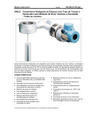
1. MOUNTING TO ACTUATORS<br />
Mounting adapters<br />
Be sure to have the right mounting adapter.<br />
Option N:<br />
NAMUR mounting, according to IEC 534-6<br />
Direct mounting to FoxPak and FoxTop actuators<br />
Rotary actuators, according to VDI/VDE 3845<br />
Option R:<br />
Rotary actuators, according to VDI/VDE 3845<br />
Option T:<br />
Integrated mounting with air connections on rear<br />
Rotary actuators, according to VDI/VDE 3845<br />
Option D:<br />
NAMUR mounting, according to VDI/VDE 3847<br />
Rotary actuators, according to VDI/VDE 3845<br />
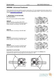
MOUNTING TO ACTUATORS<br />
During operation the flat side of the spindle 9 on the back of the positioner must always point<br />
towards the arrow 26. The working angle around this position is ±45º.<br />
'<br />
$<br />
'<br />
$
2 <strong>SRD960</strong> QG EVE0109 B-(en)<br />
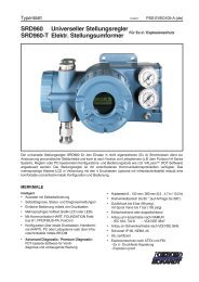
MOUNTING TO LINEAR ACTUATORS<br />
NAMUR Mounting - left hand - NAMUR Mounting - right hand -<br />
Feedback lever for linear actuators:<br />
The carrier bolt B is in the slot of the feedback lever A Direct Mounting<br />
and the compensating spring F touches the carrier bolt.<br />
Carrier bolt B:<br />
� $<br />
* .<br />
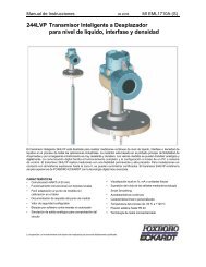
MONTAGE SUR SERVOMOTEURS ROTATIFS<br />
• Do not tighten grub screw 4 against the thread of<br />
spindle 9!<br />
• When in use the flat side of the spindle 9 must move<br />
( 0 ↔ 100%) in front of the arrow 26.<br />
• When the product temperature rises, the drive shaft 1<br />
increases in length. Therefore, the rotary adapter 3 must<br />
be mounted so that approx. 1 mm (0.04 in.) of clearance<br />
results between the drive shaft 1 and the rotary adapter 3.<br />
This is achieved by placing an appropriate number of<br />
washers 5, on the feedback spindle 9, before attaching the<br />
rotary adapter. Two washers should result in a clearance<br />
of 1 mm.<br />
!<br />
1 Threaded sleeve<br />
2 Stud<br />
3 Coupling piece<br />
)
QG EVE0109 B-(en) <strong>SRD960</strong> 3<br />
2. CONNECTIONS<br />
Actuator, left turning Actuator, right turning<br />
"<br />
'<br />
Check before mounting fittings and cable glands if threads<br />
are matching, otherwise housing can be damaged.<br />
Type of thread is marked at housing.<br />
Ground:<br />
Connect earth cable to screw #1 or screw #2 (in the<br />
electrical connection compartment).<br />
PNEUMATIC CONNECTIONS<br />
#<br />
!<br />
Air supply (s): 1.4 to 6 bar (but not more than the max. pressure of actuator), free of oil, dust and water!<br />
y1 open close close<br />
Direct mounting (simple acting) Simple acting Double acting<br />
'<br />
"<br />
#<br />
!
4 <strong>SRD960</strong> QG EVE0109 B-(en)<br />
A<br />
3. ELECTRICAL CONNECTIONS<br />
B<br />
3.2 Limit Switch<br />
3.2.1 <strong>SRD960</strong>-xxxT or U<br />
Two-wire proximity sensors, Acc. to DIN 19234 or NAMUR<br />
41+ 42- 51+ 52-<br />
3.2.3 <strong>SRD960</strong>-xxxV<br />
Electric terminal B<br />
Switching amplifier<br />
Switching amplifier<br />
3.1 Setpoint<br />
3.1.1 <strong>SRD960</strong>-xD (Intelligent w/o comm.)<br />
<strong>SRD960</strong>-xH (HART)<br />
<strong>SRD960</strong>-xA (Analog)<br />
3.1.2 <strong>SRD960</strong>-xF (FoxCom digital)<br />
3.1.3 <strong>SRD960</strong>-xP (PROFIBUS PA)<br />
<strong>SRD960</strong>-xQ (FIELDBUS FF)<br />
11 12<br />
Electric terminal A<br />
3.2.2 <strong>SRD960</strong>-xxxR<br />
41+ 43- 42 52<br />
Contact 2<br />
Contact 1<br />
Electric terminal B<br />
Supply voltage DC 10 to 30 V<br />
Warning: For connection of micro switches please refer to MI (Master Instruction) and respect the<br />
safety requirements described in document EX EVE0001.<br />
3.3 Additional i/o<br />
#2 Earth connection<br />
in electrical connection<br />
compartment.<br />
3.3.1 Two binary outputs (<strong>SRD960</strong>-xxP)<br />
Two-wire system, acc. to DIN 19234 or<br />
switched output<br />
3.3.2 Two binary inputs (<strong>SRD960</strong>-xxB)<br />
Binary inputs with internal supply for connection<br />
of sensors or switches (switch closed for a<br />
normal operation!)<br />
3.3.3 Position feedback 4 to 20 mA and 1 Alarm<br />
(<strong>SRD960</strong>-xxQ)<br />
Analog output 4 to 20 mA and Binary output<br />
Two-wire system acc. to DIN 19234 or<br />
switched.<br />
3.3.4 Two binary in-/outputs (<strong>SRD960</strong>-xxE)<br />
Two-wire system acc. to DIN 19234 or switched<br />
in-/output.<br />
The safety requirements must be observed.<br />
*! Loosen protection screw first, to open the cover and<br />
access the electrical connection compartment.<br />
This screw also unlocks the cover for electronic<br />
compartment<br />
11+ 12-<br />
11+ 12-<br />
81+ 82- 83+ 84-<br />
13+ 14-<br />
15+ 16-<br />
81+ 82- 31+ 32-<br />
81+ 82- 83+ 84-<br />
Input 4 to 20 mA<br />
Electric terminal A<br />
Electric terminal A<br />
Supply voltage DC 13 to 36 V<br />
Bus connection acc. to IEC 1158-2<br />
Supply voltage DC 9 to 32 V<br />
Electric terminal B<br />
External power supply<br />
External power supply<br />
Electric terminal B<br />
Electric terminal B<br />
Analog output 4 to 20 mA,<br />
Two-wire system, supplied with extern<br />
power supply.<br />
External power supply<br />
Electric terminal B<br />
Binary in-/output,<br />
Two-wire system, supplied with ext.<br />
power supply<br />
Binary in-/output,<br />
Two-wire system, supplied with ext.<br />
power supply
QG EVE0109 B-(en) <strong>SRD960</strong> 5<br />
4. START UP (Setting by means of local keys and LCD / LEDs)<br />
After mounting the positioner on the actuator, air and electrical input connected, you can start-up the SRD.<br />
The <strong>SRD960</strong> can be adjusted by means of a local key-pad and LCD / LED display.<br />
Attention: Do not touch behind the positioner housing while operating the keys! DANGER OF<br />
INJURIES!<br />
Description of display LCD Push buttons<br />
Process variable<br />
87.5 %<br />
Valve position<br />
Process variable and diagnostics<br />
87.5 %<br />
Valve position<br />
Ctrl diff error<br />
At configuration: Main Menu<br />
SRD Main Menu<br />
1 Mounting<br />
2 Autostart<br />
3 Valve Action<br />
At configuration the selected item is displayed with dark background. Further Menus with (+) key.<br />
Configuration and operation with push buttons …<br />
and LCD: and LED display:<br />
An already configurated device may show the An already configurated device is IN OPERATION<br />
following display: after power up, and all LEDs are off.<br />
87.5 %<br />
Valve position<br />
For configuration press (�) and Main Menu appears. For configuration press (�), and LEDs ‘M/F’ and<br />
‘1’ flash (= Menu 1 is offered).<br />
If the SRD wasn’t configurated yet, the Main If the SRD wasn’t configurated yet, Menu 1 is<br />
Menu*) appears automatically after power-up: offered automatically after power-up:<br />
SRD Main Menu<br />
1 Mounting<br />
2 Autostart<br />
3 Valve Action<br />
In Menu 1 you can select the type of mounting In Menu 1 you can select the type of mounting<br />
*) On delivery the menu language in the display is English. The<br />
menu language can be changed over to another stored<br />
language. For this select 9.8.2 [german] or 9.8.3 [as ordered]<br />
and confirm with keys (UP)+(DOWN) (simultaneously).<br />
Leave menu by repeated pressing of (M) key..<br />
� (-) (+)<br />
����<br />
Main menu:<br />
enter or exit<br />
Previous menu<br />
or parameter<br />
Next menu or<br />
parameter<br />
Enter / store<br />
Legend: � LED off, � LED on, �LED flash
6 <strong>SRD960</strong> QG EVE0109 B-(en)<br />
... and LCD: ... and LED display:<br />
1 Mounting<br />
1.1 Lin left<br />
1.2 Lin right<br />
1.3 rot cclockw<br />
(Further Menus with (+) key.)<br />
SRD Main Menu<br />
1 Mounting<br />
2 Autostart<br />
3 Valve Action<br />
Press keys (����) to enter Menu ‘Type of mounting’.<br />
Select the ‘Type of mounting’ by pressing (+) or (-).<br />
Press keys (����) to confirm and save.<br />
The SRD moves back to Menu level 1 and is in Main Menu again.<br />
To enter next Menu (= Menu 2, Autostart) press<br />
(+) once.<br />
SRD Main Menu<br />
1 Mounting<br />
2 Autostart<br />
3 Valve Action<br />
2 Autostart<br />
2.1 Endpoints<br />
2.2 Standard<br />
2.3 Enhanced<br />
Different Autostart options are available:<br />
Press keys (����) to enter Menu ‘Autostart’.<br />
Select the autostart by pressing (+) or (-).<br />
2.1 Endpoints<br />
Determines only the mechanical stops of actuator/valve.<br />
2.2 Standard<br />
Autostart recommended for standard application.<br />
Linear actuator, lefthand<br />
mounted<br />
Linear actuator, righthand<br />
mounted<br />
Rotary, opening<br />
counter-clockwise<br />
Rotary, opening<br />
clockwise<br />
To enter next Menu (= Menu 2, Autostart) press<br />
(+) once, and the LEDs ‘M’ and ‘2’ flash.<br />
2.3 Enhanced<br />
Enhanced Autostart. Optimized control behaviour compared to Standard Autostart.<br />
2.4 Smooth resp.<br />
Extended Autostart. Dampened control behaviour for e.g. smaller actuators.<br />
2.5 Fast resp.<br />
Extended Autostart. Undampened control behaviour for e.g. larger actuators.<br />
Press keys (����) to confirm and to launch Autostart.<br />
Standard Autostart<br />
The automatic adaptation to the valve is composed of a sequence of steps, explained on the LCD or<br />
indicated by the LEDs.<br />
Following the last step the device is IN OPERATION
QG EVE0109 B-(en) <strong>SRD960</strong> 7<br />
Menustructure for SRD991/<strong>SRD960</strong> with LCD<br />
SRD Main Menu<br />
Menu Factory Description<br />
configuration<br />
1 Mounting<br />
1.1 Lin left � Linear actuator, left-hand or direct mounting<br />
1.2 Lin right Linear actuator, right-hand mounting<br />
1.3 Rot cclockw Rotary actuator, opening counter-clockwise<br />
1.4 Rot clockw Rotary actuator, opening clockwise<br />
2 Autostart<br />
2.1 Endpoints Adaptation of the mechanical stops only<br />
2.2 Standard Autostart recommended for standard application<br />
2.3 Extended Extended Autostart, fast response with maybe overshoot<br />
2.4 Smooth resp. Extended Autostart, damped response to avoid overshoot<br />
2.5 Fast resp. Extended Autostart, very fast response with limited overshoot<br />
3 Valve Action<br />
3.1 SRD<br />
3.1.1 Direct � Valve opens with increasing setpoint value<br />
3.1.2 Reverse Valve closes with increasing setpoint value<br />
3.2 Feedback<br />
3.2.1 Direct � Increasing Current with increasing valve position<br />
3.2.2 Reverse Decreasing Current with increasing valve position<br />
4 Character<br />
4.1 Linear � Linear characteristic<br />
4.2 Eq Perc 1:50 Equal percentage characteristic 1:50<br />
4.3 Quick open Inverse equal percentage characteristic 1:50 (quick opening)<br />
4.4 Customer Custom characteristic<br />
5 Limits/alarms<br />
Not locally available with LED versions of communication FF and<br />
Profibus<br />
5.1 Lower limit 0 % Closing limit is set to input value<br />
5.2 Cutoff low 1 % 0%-tight sealing point is set to input value<br />
5.3 Cutoff high 100 % 100%-tight sealing point is set to input value<br />
5.4 Upper limit 100 % Opening limit is set to input value<br />
5.5 Splitr 0 % 4 mA Split range 0 %: input value corresponds to 0 %<br />
5.6 Splitr 100 % 20 mA Split range 100 %: input value corresponds to 100 %<br />
5.7 Lower Alarm -10 % Lower position alarm on output 1 is set to input value<br />
5.8 Upper Alarm 110 % Upper position alarm on output 2 is set to input value<br />
5.9 Valve 0% 4 mA Configuration of rated-stroke of 0% at 4 mA<br />
5.10 Valve 100% 20 mA Configuration of rated-stroke of 100% at 20 mA<br />
5.11 Stroke Range x° / 20mm Configuration of nominal travel<br />
5.12 Units SI Configuration of temperature and pressure unit SI or Anglo US<br />
6 Parameters<br />
6.1 Gain closing 15 P: Proportional gain for ‘close valve’<br />
6.2 Gain opening 2 P: Proportional gain for ‘open valve’<br />
6.3 Res time cl 7.5 I: Integration time for ‘close valve’<br />
6.4 Res time op 2.4 I: Integration time for ‘open valve’<br />
6.5 Rate lim cl 0.35 T63: Setting time for ‘close valve’<br />
6.6 Rate lim op 0.35 T63: Setting time for ‘open valve’<br />
6.7 Control gap 0.1 Permitted neutral zone for control difference<br />
7 Output Manual setting of IP-Module for testing of pneumatic output<br />
8 Setpoint Manual setting of valve position<br />
8.1 12.5% Steps Setpoint changes of 12.5% steps by using push buttons Up or Down<br />
8.2 1% Steps Setpoint changes of 1% steps by using push buttons Up or Down<br />
8.3 Do PST Start Partial Strok Test<br />
Continue on the next page...
8 <strong>SRD960</strong> QG EVE0109 B-(en)<br />
9 Workbench<br />
9.1 Reset Config Resetting of configuration to setting “ex factory”<br />
9.2 Calib. 4 mA Calibrate input current to 4 mA<br />
9.3 Calib. 20 mA Calibrate input current to 20 mA<br />
9.4 Calib. -45° Calibrate position measuring value to –45°<br />
9.5 Calib. +45° Calibrate position measuring value to +45°<br />
9.6 Reset all 1 Resetting of configuration and Calibration (!) to “ex factory” setting for<br />
single-acting output<br />
9.7 Reset all 2 Resetting of configuration and Calibration (!) to “ex factory” setting for<br />
double-acting output<br />
9.8 Go Online<br />
9.9 Menu Lang<br />
Setting position into mode Online<br />
9.9.1 English � Standard<br />
9.9.2 Deutsch<br />
Standard<br />
9.9.3 Français<br />
9.10 LCD orient<br />
Preselected / Freely Defiable<br />
9.10.1 Normal � Normal orientation of writing on LCD<br />
9.10.2 Flipped<br />
Reverse orientation of writing on LCD<br />
9.11 Cal. Feedbk Calibration of output current of position transmitter<br />
9.11.1 Cal 4mA Calibration of 0% at 4mA<br />
9.11.2 Cal. 20mA Calibration of 100% at 20mA<br />
10 - not available - for HART<br />
10 Profibus PA - Bus Address<br />
10.1 Address LSB Ratio from Dec. 0 / Hex 00 to Dec. 15 / Hex 0F<br />
10.2 Address MSB Ration from Dec. 0 / Hex 00 to Dec. 112 / Hex 70<br />
10.3 Address 126 Display of Bus Address from Dec. 1 to 127 (Hex 00 to 7F)<br />
10 FOUNDATION Fieldbus H1<br />
10.1 Simulate<br />
Disabled � Simulate disabled<br />
Enabled Simulate enabled<br />
10.2 Profile<br />
Link Master � Link Master active<br />
Basic Device Link Master de-activated<br />
Additional Documentation for this product:<br />
Technical Information of Attachment Kits for <strong>Positioner</strong>s<br />
TI EVE0011 A Overview of Attachment Kits of all positioners on actuators/valves of different<br />
manufacturers<br />
Master Instructions:<br />
MI EVE0109 A <strong>SRD960</strong> -all versions-<br />
Technical Information for Fieldbus-Communication:<br />
TI EVE0105 P SRD991/960 -PROFIBUS-PA<br />
TI EVE0105 Q SRD991/960 -FOUNDATION Fieldbus H1<br />
Master Instruction for HART-Communication:<br />
MI EVE0105 B HART with Hand-Held Terminal<br />
Master Instruction for configuration- and operation-software PC20<br />
nd integration into Foxboro I/A Series System:<br />
MI 020-495 HART / FoxCom / PROFIBUS-PA and IRCOM with PC<br />
by means of PC20/ IFDC<br />
B 0193 VH I/A Series System<br />
Subject to alterations – reprinting, copying and translation prohibited. Products and publications are normally<br />
quoted here without reference to existing patent, registered utility models or trademarks. The lack of any<br />
such reference does not justify the assumption that a product or symbol is free.<br />
<strong>FOXBORO</strong> <strong>ECKARDT</strong> <strong>GmbH</strong> <strong>ECKARDT</strong> S.A.S.<br />
Pragstrasse 82 20 rue de la Marne<br />
D-70376 Stuttgart F-68360 Soultz<br />
Germany France<br />
Tel. + 49(0)711 502-0 Tel. + 33 (0)3 89 62 15 30<br />
Fax + 49(0)711 502-597 Fax + 33 (0)3 89 62 14 85<br />
http://www.foxboro-eckardt.de DOKT 534 022 056 http://www.foxboro-eckardt.com
Kurzanleitung 02.2010 QG EVE0109 B-(de)<br />
<strong>SRD960</strong> Universeller Stellungsregler<br />
Diese Instruktion dienen als Anleitung für eine schnelle Inbetriebnahme. Ausführlichere Informationen<br />
sind in Dokumenten ”Inbetriebnahme- und Wartungsanleitung” und ”Typenblatt”, die Sie auch auf unserer<br />
Webseite www.foxboro-eckardt.de finden.<br />
1. MONTAGE AN ANTRIEBE<br />
Monatge-Adapter<br />
Stellen Sie sicher, dass der richtige Adapter vorliegt.<br />
Option N:<br />
NAMUR-Anbau, nach IEC 534-6<br />
Direktanbau an FoxPak und FoxTop Antriebe<br />
Schwenkantriebe nach VDI/VDE 3845<br />
Option R:<br />
Schwenkantriebe nach VDI/VDE 3845<br />
Option T:<br />
Integrierte Montage mit rückseitigen Luftanschlüssen<br />
Schwenkantriebe nach VDI/VDE 3845<br />
Option D:<br />
NAMUR-Anbau, nach VDI/VDE 3847<br />
Schwenkantriebe nach VDI/VDE 3845<br />
Mittellage einstellen<br />
Auf der Rückseite des Stellungsreglers ist die Anlenkwelle 9. Die Anlenkwelle steht richtig, wenn der<br />
Pfeil 26 auf die Flachstelle der Anlenkwelle zeigt. Der Arbeitsbereich ist dann ± 45 Grad um diese<br />
Position.<br />
'<br />
$<br />
'<br />
$
2 <strong>SRD960</strong> QG EVE0109 B-(de)<br />
MONTAGE AN LINEARANTRIEBE<br />
Anbau nach NAMUR - linksseitig - Anbau nach NAMUR - rechtsseitig -<br />
Anlenkhebel bei Linearantrieben:<br />
Der Anlenkbolzen B greift in den Schlitz des Anlenkhebels Direktanbau<br />
A ein. Die Ausgleichsfeder F liegt am Anlenkbolzen an.<br />
Anlenkbolzen B:<br />
� $<br />
* .<br />
ANBAU AN SCHWENKANTRIEBE<br />
• Den Gewindestift 4 NICHT gegen das Gewinde der<br />
Anlenkwelle 9 schrauben, sondern gegen die Flachstelle!<br />
• Bei 50% Sollwert muss sich die Flachstelle der<br />
Anlenkwelle 9 vor dem Pfeil 26 befinden.<br />
• Bei steigender Produkttemperatur reduziert sich der<br />
Abstand zwischen Antriebswelle 1 und Kupplungsstück 3.<br />
Daher sollte ein Spiel von etwa 1 mm gewährleistet sein.<br />
Dies wird erreicht, indem vor dem Anschrauben des<br />
Kupplungsstücks eine entsprechende Anzahl von<br />
Scheiben 5 auf die Anlenkwelle 9 gelegt wird. Die genaue<br />
Anzahl der Scheiben ist durch Versuch zu bestimmen. 2<br />
Scheiben sollten ein Spiel von ca. 1 mm ergeben.<br />
!<br />
1 Gewindehülse<br />
2 Gewindestift<br />
3 Kupplungsstück<br />
)
QG EVE0109 B-(de) <strong>SRD960</strong> 3<br />
Anbau bei linksdrehendem Antrieb Anbau bei rechtsdrehendem Antrieb<br />
2. ANSCHLÜSSE<br />
"<br />
'<br />
Prüfen Sie vor der elektrischen und pneumatischen<br />
Verschraubungen, ob die Gewinde zueinander passen,<br />
sonst kann das Gehäuse beschädigt werden. Die Art des<br />
Gewindes ist am Gehäuse gekennzeichnet.<br />
Erdung:<br />
Anschluss der Erdleitung an Schraube #1 oder der<br />
Schraube #2 (im Klemmenraum, siehe nächste Seite).<br />
PNEUMATISCHE ANSCHLÜSSE<br />
#<br />
!<br />
Zuluftversorgung (s): 1,4 bis 6 bar (aber nicht höher als der Maximaldruck des Antriebes), frei von Öl,<br />
Staub und Wasser!<br />
y1 offen Verschlossen Verschlossen<br />
Direktanbau (Einfachwirkend) Einfachwirkend Doppeltwirkend<br />
'<br />
"<br />
#<br />
!
4 <strong>SRD960</strong> QG EVE0109 B-(de)<br />
A<br />
3. ELEKTRISCHE ANSCHLÜSSE<br />
B<br />
3.2 Grenzwertgeber<br />
41+ 42- 51+ 52-<br />
#2 Erdungsanschluss<br />
im elektrischen<br />
Anschlussraum.<br />
3.2.1 <strong>SRD960</strong>-xxxT or U<br />
Zweidraht-Sensoren, nach DIN 19234 oder NAMUR<br />
Anschlussklemme B<br />
Schaltverstärker<br />
Schaltverstärker<br />
3.1 Sollwert<br />
3.1.1 <strong>SRD960</strong>-xD (ohne Kommunikation)<br />
<strong>SRD960</strong>-xH (HART)<br />
<strong>SRD960</strong>-xA (Analog)<br />
3.1.2 <strong>SRD960</strong>-xF (FoxCom digital)<br />
3.1.3 <strong>SRD960</strong>-xP (PROFIBUS PA)<br />
<strong>SRD960</strong>-xQ (FIELDBUS FF)<br />
11 12 Anschlussklemme A<br />
3.2.2 <strong>SRD960</strong>-xxxR<br />
41+ 43- 42 52<br />
Kontakt 2<br />
Kontakt 1<br />
Anschlussklemme B<br />
Versorgungsspannung DC 10 bis 30 V<br />
3.2.3 <strong>SRD960</strong>-xxxV<br />
Achtung: Beim Anschluss der Mikroschalter sind die Hinweise in der MI sowie die Sicherheitsbestimmungen<br />
im Dokument EX EVE0001 zu beachten.<br />
3.3 Zusätzliche Ein-/Ausgänge<br />
3.3.1 Zwei Binärausgänge (<strong>SRD960</strong>-xxP)<br />
Zweidraht-System nach DIN 19234 oder<br />
Schaltausgang<br />
3.3.2 Zwei Binäreingänge (<strong>SRD960</strong>-xxB)<br />
Binäreingänge mit interner Versorgung zum<br />
Anschluss von Schaltern oder Sensoren<br />
(Schalter geschlossen im Normal-Zustand!)<br />
3.3.3 Stellungsrückmeldung 4 bis 20 mA und<br />
1 Alarm (<strong>SRD960</strong>-xxQ)<br />
Analogausgang 4-20 mA und Binarausgang<br />
Zweidraht-System nach DIN 19234 oder<br />
Schaltend<br />
3.3.4 Zwei Binärein-/ausgänge (<strong>SRD960</strong>-xxE)<br />
Zweidraht-System nach DIN 19234 oder<br />
Schaltein-/ausgang<br />
Die Sicherheitsbestimmungen sind zu beachten.<br />
*! Zuerst die Sicherungsschraube (*) lösen, dann kann<br />
der Deckel vom elektrisch Anschlussraum abgeschraubt<br />
werden.<br />
Diese Schraube entriegelt auch den Schraubendeckel<br />
des Elektronikraumes.<br />
11+ 12-<br />
11+ 12-<br />
81+ 82- 83+ 84-<br />
13+ 14-<br />
15+ 16-<br />
81+ 82- 31+ 32-<br />
81+ 82- 83+ 84-<br />
Anschlussklemme A<br />
Eingang 4 bis 20 mA<br />
Anschlussklemme A<br />
Versorgungsspannung DC 13 bis 36 V<br />
Busanschluss nach IEC 1158-2<br />
Versorgungsspannung DC 9 bis 32 V<br />
Anschlussklemme B<br />
Externes Speisegerät<br />
Externes Speisegerät<br />
Anschlussklemme B<br />
Anschlussklemme B<br />
Analog-Ausgang 4 bis 20 mA,<br />
Zweidraht-System,<br />
zu versorgen mit ext. Speisegerät<br />
Externes Speisegerät<br />
Anschlussklemme B<br />
Binar-Ein-/Ausgang,<br />
Zweidraht-System,<br />
zu versorgen mit ext. Speisegerät<br />
Binar-Ein-/Ausgang,<br />
Zweidraht-System,<br />
zu versorgen mit ext. Speisegerät
QG EVE0109 B-(de) <strong>SRD960</strong> 5<br />
4. INBETRIEBNAHME (Einstellung mit lokalen Tasten und LCD / LEDs)<br />
Nach Anbau an den Antrieb, pneumatischem und elektrischem Anschluss, können Sie den SRD in<br />
Betrieb nehmen.Die Inbetriebnahme kann mit den lokalen Drucktasten und dem LCD / LED-Anzeige<br />
erfolgen.<br />
VORSICHT: IM BETRIEB NICHT HINTER DAS GERÄT FASSEN! VERLETZUNGSGEFAHR!<br />
Darstellungen auf dem Display *) Drucktasten<br />
Prozessvariable<br />
87.5 %<br />
Ventilposition<br />
Prozessvariable und Diagnose<br />
87.5 %<br />
Ventilposition<br />
Regelabweichung<br />
Beim Konfigurieren: Hauptmenü<br />
SRD Hauptmenu<br />
1 Anbau<br />
2 Autostart<br />
3 Wirkungsweise<br />
Beim Konfigurieren ist der jeweils angewählte Menüpunkt dunkel hinterlegt. Weitere Menüpunkte mit der<br />
(+)-Taste.<br />
Konfigurierung und Bedienung mit Drucktasten …<br />
…und LCD: …und LED-Anzeige:<br />
Ein bereits konfigurierter SRD hat z.B. folgende Bei einem bereits konfigurierten SRD sind im<br />
Anzeige: Betrieb alle LEDs aus.<br />
87.5 %<br />
Ventilposition<br />
Zum Konfigurieren (�) drücken und es erscheint Zum Konfigurieren (�) drücken und LEDs M und<br />
das Hauptmenü. 1 blinken (= Menü 1 wird angeboten).<br />
Wenn der SRD noch nicht konfiguriert ist, er- Wenn der SRD noch nicht konfiguriert ist, wird<br />
nach<br />
scheint nach dem Einschalten automatisch das dem Einschalten automatisch Menü 1 angeboten:<br />
Hauptmenü: *):<br />
SRD Hauptmenu<br />
1 Anbau<br />
2 Autostart<br />
3 Wirkungsweise<br />
In Menü 1 kann die Anbauseite ausgewählt werden. In Menü 1 kann die Anbauseite ausgewählt<br />
werden.<br />
*) Im Auslieferungszustand ist die voreingestellte Menüsprache im<br />
Display in Englisch. Die Menüsprache kann z.B. auf Deutsch<br />
umgestellt werden. Hierzu 9.8.2 auswählen, mit den Tasten (+)+(-)<br />
(gleichzeitig) bestätigen und durch mehrmaliges Betätigen von (M)<br />
das Menü wieder verlassen.<br />
� (-) (+)<br />
����<br />
Hauptmenü<br />
aufrufen oder<br />
verlassen<br />
Ein Menü-<br />
Ebene zurück<br />
oder voriger<br />
Parameter<br />
Eine Menü-<br />
Ebene weiter<br />
oder nächster<br />
Parameter<br />
Eingabe /<br />
Speichern<br />
Legende : � LED Aus, � LED Ein, �LED Blinkt
6 <strong>SRD960</strong> QG EVE0109 B-(de)<br />
... und LCD: ... und LED-Anzeige:<br />
Durch Drücken der Tasten (����) kommt der SRD in das Menü zur Auswahl ‘Anbauseite’. Wählen Sie dann<br />
mit den Tasten (+) oder (-) die Anbauseite aus.<br />
1 Anbau<br />
1.1 Lin links<br />
1.2 Lin rechts<br />
1.3 Links-Dreh<br />
(Weitere Menupunkte mit der (+)-Taste.)<br />
SRD Hauptmenü<br />
1 Anbau<br />
2 Autostart<br />
3 Wirkungsweise<br />
Mit Tasten (����) bestätigen und speichern.<br />
Der SRD springt eine Menü-Ebene zurück und ist wieder im Hauptmenü.<br />
Zum nächsten Menü (= Menü 2, Autostart)<br />
1x (+) drücken.<br />
SRD Hauptmenü<br />
1 Anbau<br />
2 Autostart<br />
3 Wirkungsweise<br />
start<br />
2.1 Anschläge<br />
2.2 Standard<br />
2.3 Erweitert<br />
Hubantrieb,<br />
Linksanbau<br />
Hubantrieb,<br />
Rechtsanbau<br />
Schwenkantrieb, öffnet<br />
im Gegenuhrzeigersinn<br />
Schwenkantrieb, öffnet<br />
im Uhrzeigersinn<br />
Zum nächsten Menü (= Menü 2, Autostart)1x (+)<br />
drücken, und LEDs ‘M’ und ‘2’ blinken.<br />
Durch Drücken der Tasten (����) kommt der SRD in das Menü zur Auswahl ‘Autostart’.<br />
Wählen Sie dann mit den Tasten (+) oder (-) den gewünschten Autostart-Modi aus.<br />
Verschiedene Autostart-Modi sind verfügbar:<br />
2.1 Anschläge<br />
Ermittelt nur die mechanischen Anschläge des Antriebs/Ventils.<br />
2.2 Standard<br />
Empfohlener Autostart für Standard-Applikationen.<br />
Standard Autostart<br />
2.3 Erweitert<br />
Erweiterter Autostart. Zur Optimierung der Reglereinstellung gegenüber dem Standard-Modus.<br />
2.4 Sanfte Antw.<br />
Erweiterter Autostart. Gedämpfte Reglereinstellung für z.B. kleinere Antriebe.<br />
2.5 Schnel.Antw.<br />
Erweiterter Autostart. Ungedämpfte aggressivere Reglereinstellung für z.B. größere Antriebe.<br />
Mit den Tasten (����) bestätigen, um Autostart einzuleiten.<br />
Die automatische Anpassung an den Antrieb erfolgt in nacheinander ablaufenden Schritten, die auf dem<br />
LCD und LEDs angezeigt werden.<br />
Nach dem letzten Schritt ist der Stellungsregler IN BETRIEB.
QG EVE0109 B-(de) <strong>SRD960</strong> 7<br />
Menüstruktur des SRD991/<strong>SRD960</strong> mittels LCD<br />
SRD Hauptmenü<br />
Menüpunkt / Einstellung Beschreibung:<br />
LCD-Anzeige ab Werk<br />
1 Anbau<br />
1.1 Lin links � Hubantrieb, Anbau links, Direktanbau<br />
1.2 Lin rechts Hubantrieb, Anbau rechts<br />
1.3 links-Dreh Schwenkantrieb, im Gegenuhrzeigersinn öffnend<br />
1.4 Rechts-Dreh Schwenkantrieb, im Uhrzeigersinn öffnend<br />
2 Autostart<br />
2.1 Anschläge Ermittlung der mechanischen Anschläge<br />
2.2 Standard Autostart empfohlen für Standard-Applikationen<br />
2.3 Erweitert Erweiterter Autostart. Optimierung der Reglereinstellung gegenüber 2.2<br />
2.4 Sanfte Antw. Erweiterter Autostart. Gedämpfte Reglereinstellung für z.B. kleinere Antriebe.<br />
Erweiterter Autostart. Ungedämpfte aggressivere Reglereinstellung für z.B.<br />
2.5 Schnel.Antw.<br />
größere Antriebe.<br />
3 Wirkungsweise<br />
3.1 SRD<br />
3.1.1 Gleichsinnig � Ventil öffnet mit zunehmendem Sollwert<br />
3.1.2 Gegensinnig Ventil schließt mit zunehmendem Sollwert<br />
3.2 Rückmeldung<br />
3.2.1 Gleichsinnig � Zunehmende Strom mit zunehmende Ventilposition<br />
3.2.2 Gegensinnig Abnehmende Strom mit zunehmende Ventilposition<br />
4 Kennlinie<br />
4.1 Linear � Lineare Kennlinie<br />
4.2 Gl-Proz 1:50 Gleichprozentige Kennlinie 1:50<br />
4.3 Invers gl-% Invers gleichprozentige Kennlinie 1:50 (schnell öffnend)<br />
4.4 Benutzerspez Kundenspezifische Kennlinie (konf. mittels Kommunikation)<br />
5 Grenz./Alarme Nicht für Versionen mit LED und Kommunikation FF und Profibus vor HW-Rev. 3.3<br />
5.1 Unt. Hubbegr 0 % Schließgrenze auf Eingangswert setzen<br />
5.2 Dichts. Unt 1 % 0%-Dichtschließ-Punkt auf Eingangswert setzen<br />
5.3 Dichts. Oben 100 % 100%-Dichtschließ-Punkt auf Eingangswert setzen<br />
5.4 Obere Hubbeg 100 % Öffnungsgrenze wird auf Eingangswert gesetzt.<br />
5.5 Splitr 0 %" 4 mA Split range 0 %: Eingangswert entspricht 0 %<br />
5.6 Splitr 100 % 20 mA Split range 100 %: Eingangswert entspricht 100 %<br />
5.7 Unter. Alarm -10 % Unterer Positionsalarm auf Ausgang 1 auf den Eingangswert setzen<br />
5.8 Oberer Alarm 110 % Obere Positionsalarm auf Ausgang 2 auf den Eingangswert setzen<br />
5.9 Ventil 0% 4 mA Konfiguration des Nennhubes von 0% bei 4 mA<br />
5.10 Ventil 100% 20 mA Konfiguration des Nennhubes von 100% bei 20 mA<br />
5.11 Stellber. x° / 20mm Einstellung des Nennhubes für Hubantriebe<br />
5.12 Einheiten SI Konfiguration der Temparatur und Druckeinheiten SI oder Anglo US<br />
6 Parameter<br />
6.1 Verst. Zu 15 P: Proportional-Verstärkung für ‘Ventil schließen’<br />
6.2 Verst. Auf 2 P: Proportional-Verstärkung für ‘Ventil öffnen’<br />
6.3 Int-Zeit zu 7,5 I: Integrationszeit für ‘Ventil schließen’<br />
6.4 Int-Zeit auf 2,4 I: Integrationszeit für ‘Ventil öffnen’<br />
6.5 Stellzeit zu 0,35 T 63: Stellzeit für ‘Ventil schließen’<br />
6.6 Stellzeit au 0,35 T 63: Stellzeit für ‘Ventil öffnen’<br />
6.7 Totzone 0,1 Zulässige Totzone für Regeldifferenz<br />
7 Pneumatikausg Direkt Ansteuerung das IP-Modul zum Testen der Pneumatik<br />
8 Sollwert Manuelle Vorgabe der Ventilstellung zur Vorgabe von Sollwertsprüngen<br />
8.2 12.5-%-Schr. Sollwert-Vorgabe in 12,5% Schritten mittels UP oder DOWN<br />
8.2 1-%-Schritte Sollwert-Vorgabe in 1% Schritten mittels UP oder DOWN<br />
8.3 PST Starten Straten Patrial Stroke Test<br />
Fortsetzung auf der nächsten Seite...
8 <strong>SRD960</strong> QG EVE0109 B-(de)<br />
9 Werkstatt<br />
9.1 Werkseinst. Rücksetzen der Konfiguration auf Einstellung ‘ab Werk’ danach Zustand<br />
AUSSER BETRIEB<br />
9.2 Kalib. 4 mA Eingangsstrom auf 4 mA kalibrieren<br />
9.3 Kalib. 20 mA Eingangsstrom auf 20 mA kalibrieren<br />
9.4 Kalib. -45° Positionsmeßwert auf –45° kalibrieren<br />
9.5 Kalib. +45° Positionsmeßwert auf +45° kalibrieren<br />
9.6 Grundeinst 1<br />
Rücksetzen der Konfiguration und Kalibrierungen (!) auf Einstellung ‘ab Werk’<br />
für einfachwirkenden Ausgang –> danach Zustand AUSSER BETRIEB<br />
9.7 Grundeinst 2<br />
Rücksetzen der Konfiguration und Kalibrierungen (!) auf Einstellung ‘ab Werk’<br />
für doppeltwirkenden Ausgang –> danach Zustand AUSSER BETRIEB<br />
9.8 Menüsprache<br />
Setze Online<br />
9.9 Menüsprache<br />
Stellungsregler Online Setzen<br />
9.9.1 English � Standard<br />
9.9.2 Deutsch Standard<br />
9.9.3 Français<br />
9.10 LCD Orient<br />
Vorselektierte / Frei wählbare Menüsprache<br />
9.10.1 Normal � Normale Ausrichtung der LCD-Anzeige<br />
9.10.2 Gedreht Gedrehte Ausrichtung der LCD-Anzeige<br />
9.11 Kal. Feedbk Kalibrierung des Analogen Stellungsumformers 4-20 mA<br />
9.11.1 Kal. 4mA Kalibrierung von 0% bei 4mA<br />
9.11.2 Kal. 20mA Kalibrierung von 100% bei 20mA<br />
10 - nicht belegt - für HART<br />
10 Busadresse - Profibus PA<br />
10.1 Adresse LSB Bereich von Dez. 0 / Hex 00 bis Dez. 15 / Hex 0F<br />
10.2 Adresse MSB Bereich von Dez. 0 / Hex 00 bis Dez. 112 / Hex 70<br />
10.3 Adresse 126 Anzeige der Busadresse von Dez. 1...127 (Hex 00...7F)<br />
10 FOUNDATION Fieldbus H1<br />
10.1 Simulation<br />
Gesperrt � Simulation gesperrt<br />
Freigegeben Simulation freigegeben<br />
10.2 Profil<br />
Link Master � Link Master aktiv<br />
Basisgerät kein Link Master<br />
Additional Documentation for this product:<br />
Technical Information of Attachment Kits for <strong>Positioner</strong>s<br />
TI EVE0011 A Overview of Attachment Kits of all positioners on actuators/valves of different<br />
manufacturers<br />
Master Instructions:<br />
MI EVE0109 A <strong>SRD960</strong> -all versions-<br />
Technical Information for Fieldbus-Communication:<br />
TI EVE0105 P SRD991/960 -PROFIBUS-PA<br />
TI EVE0105 Q SRD991/960 -FOUNDATION Fieldbus H1<br />
Master Instruction for HART-Communication:<br />
MI EVE0105 B HART with Hand-Held Terminal<br />
Master Instruction for configuration- and operation-software PC20<br />
nd integration into Foxboro I/A Series System:<br />
MI 020-495 HART / FoxCom / PROFIBUS-PA and IRCOM with PC<br />
by means of PC20/ IFDC<br />
B 0193 VH I/A Series System<br />
Änderungen vorbehalten – Nachdruck, Vervielfältigung und Übersetzung nicht gestattet. Die Nennung von Waren<br />
oder Schriften erfolgt in der Regel ohne Erwähnung bestehender Patente, Gebrauchsmuster oder Warenzeichen.<br />
Das Fehlen eines solchen Hinweises begründet nicht die Annahme, eine Ware oder ein Zeichen seien frei.<br />
<strong>FOXBORO</strong> <strong>ECKARDT</strong> <strong>GmbH</strong> <strong>ECKARDT</strong> S.A.S.<br />
Pragstrasse 82 20 rue de la Marne<br />
D-70376 Stuttgart F-68360 Soultz<br />
Germany France<br />
Tel. + 49(0)711 502-0 Tel. + 33 (0)3 89 62 15 30<br />
Fax + 49(0)711 502-597 Fax + 33 (0)3 89 62 14 85<br />
http://www.foxboro-eckardt.de DOKT 534 022 056 http://www.foxboro-eckardt.com
Guide rapide d’utilisation 02.2010 QG EVE0109 B-(fr)<br />
<strong>SRD960</strong> Positionneur universel<br />
Ces instructions sont une aide pour une mise en service rapide. Pour plus d’information sur le produit<br />
veuillez vous reporter aux documents standards «fiche technique» et «Instructions de montage et de<br />
service» disponible sur internet à l’adresse www.foxboro-eckardt.com.<br />
1. MONTAGE SUR LE SERVOMOTEUR<br />
Plaque de préparation pour le montage<br />
Assurer vous que vous possédez la plaque adéquate<br />
pour la préparation au montage.<br />
Option N:<br />
Montage NAMUR selon IEC 534-6<br />
Montage direct sur servomoteur FoxPak et FoxTop<br />
Servomoteur rotatif selon VDI/VDE 3845<br />
Option R:<br />
Servomoteur rotatif selon VDI/VDE 3845<br />
Option T:<br />
Montage intégré avec sortie d'air postérieure<br />
Servomoteur rotatif selon VDI/VDE 3845<br />
Option D:<br />
Montage NAMUR selon VDI/VDE 3847<br />
Servomoteur rotatif selon VDI/VDE 3845<br />
Mise en position<br />
En fonctionnement la flèche 26 doit toujours pointer le méplat de l'axe de traversée 9. La zone de travail est de ±<br />
45° autour de la position centrale.<br />
'<br />
$<br />
'<br />
$
2 <strong>SRD960</strong> QG EVE0109 B-(fr)<br />
MONTAGE SUR SERVOMOTEURS LINÉAIRES<br />
Montage NAMUR – à gauche - Montage NAMUR – à droite -<br />
Levier d’accouplement pour servomoteurs linéaires:<br />
Le doigt d’accouplement B doit se trouver dans la lumière Montage direct<br />
du levier d’accouplement A et le ressort de compensation<br />
F doit être en contact avec le doigt d’accouplement.<br />
Doigt d'entrainement B:<br />
� $<br />
* .<br />
MONTAGE SUR SERVOMOTEURS ROTATIFS<br />
• Ne pas visser la vis 4 contre le filetage de l’axe de<br />
traversée 9, mais sur le méplat!<br />
• En fonctionnement le méplat de l’axe de traversée 9 doit<br />
tourner devant la flèche 26.<br />
• L’axe du servomoteur 1 s’allonge sous l’effet de la<br />
chaleur produite lors du fonctionnement du servomoteur.<br />
C’est pourquoi l’adaptateur 3 doit être monté de façon à<br />
ce qu’il y ait, entre lui et l’axe de transmission 1, un jeu<br />
d’environ 1 mm. Ce jeu peut être obtenu en ajoutant un<br />
nombre approprié de rondelles 5 sur l’axe de traversée 9.<br />
!<br />
)<br />
1 Douille filetée<br />
2 Tige<br />
3 Pièce d'accouplement
QG EVE0109 B-(fr) <strong>SRD960</strong> 3<br />
Servomoteur, sens de rotation antihoraire Servomoteur, sens de rotation horaire<br />
2. RACCORDEMENTS<br />
"<br />
'<br />
Avant le montage des raccords pneumatiques et presse<br />
étoupe, vérifier les filetages soient compatibles.<br />
Les types de filetages sont indiqués sur le boitier.<br />
Mise à la terre:<br />
Le raccordement à la terre peut se faire avec la vis #1ou<br />
la vis #2 (à l'intérieur du compartiment raccords<br />
électriques voir page suivante).<br />
RACCORDEMENTS PNEUMATIQUES<br />
#<br />
!<br />
Air d'alimentation(s): 1,4 à 6 bar (en respectant la pression de travail maximum du servomoteur) air propre,<br />
déshuilé, sans poussière ni eau.<br />
y1 ouvert fermé fermé<br />
Montage direct (simple effet) Simple effet Double effet<br />
'<br />
"<br />
#<br />
!
4 <strong>SRD960</strong> QG EVE0109 B-(fr)<br />
A<br />
3. RACCORDEMENTS ELECTRIQUES<br />
B<br />
3.2 Fins de course<br />
41+ 42- 51+ 52-<br />
Amplificateur séparateur<br />
Amplificateur séparateur<br />
Bornier B<br />
3.1 Signal d’entrée<br />
3.1.1 <strong>SRD960</strong>-xD (sans communication)<br />
<strong>SRD960</strong>-xH (HART)<br />
<strong>SRD960</strong>-xA (Analogique)<br />
3.1.2 <strong>SRD960</strong>-xF (FoxCom digitale)<br />
3.2.1 <strong>SRD960</strong>-xxxT or U<br />
Capteurs inductifs technique deux fils, selon DIN 19234 ou NAMUR<br />
3.2.3 <strong>SRD960</strong>-xxxV<br />
3.1.3 <strong>SRD960</strong>-xP (PROFIBUS PA)<br />
<strong>SRD960</strong>-xQ (FIELDBUS FF)<br />
11 12<br />
Bornier A<br />
3.2.2 <strong>SRD960</strong>-xxxR<br />
41+ 43- 42 52<br />
Contact 2<br />
Contact 1<br />
Bornier B<br />
Tension d’alimentation DC 10 à 30 V<br />
Attention : Pour le raccordement des micro-contacts respecter les recommandations de la MI<br />
(instructions de mise en service) et du document EX EVE0001.<br />
3.3 Option Board<br />
#2 Vis de mise à la<br />
terre du compartiment<br />
raccords électriques.<br />
3.3.1 Deux sorties binaires (<strong>SRD960</strong>-xxP)<br />
Technique deux fils.<br />
Configuration selon DIN 19234 ou configuration<br />
"tout ou rien".<br />
3.3.2 Deux entrées binaires (<strong>SRD960</strong>-xxB)<br />
Entrées binaires avec alimentation interne pour<br />
raccordement sur capteurs ou contact (contacts<br />
fermés pour un fonctionnement normal!)<br />
3.3.3 Recopie de position 4-20 mA + alarme<br />
(<strong>SRD960</strong>-xxQ)<br />
Sortie analogique 4 à 20 mA et sortie binaire<br />
technique 2 fils.<br />
Configuration selon DIN 19234 ou configuration<br />
"tout ou rien".<br />
3.3.4 Deux entrées/sorties binaires (<strong>SRD960</strong>-xxE)<br />
Technique deux fils.<br />
Configuration selon DIN 19234 ou configuration<br />
"tout ou rien".<br />
Les recommandations de sécurité doivent être<br />
observées.<br />
*! Pour ouvrir le compartiment des raccords<br />
électriques il faut dévisser la vis de sécurité.<br />
Cette vis de sécurité bloque aussi l'ouverture du<br />
couvercle du compartiment électronique<br />
11+ 12-<br />
11+ 12-<br />
81+ 82- 83+ 84-<br />
13+ 14-<br />
15+ 16-<br />
81+ 82- 31+ 32-<br />
81+ 82- 83+ 84-<br />
Entrée analogique 4-20 mA<br />
Bornier A<br />
Bornier A<br />
Tension d’alimentation DC 13 à 36 V<br />
Raccordement au bus selon IEC 1158-2<br />
Tension d’alimentation DC 9 à 32 V<br />
Alimentation externe<br />
Alimentation externe<br />
Bornier B<br />
Bornier B<br />
Bornier B<br />
Sortie analogique 4-20 mA, technique<br />
deux fils, Alimentation externe.<br />
Alimentation externe<br />
Bornier B<br />
Entrée/Sortie binaire,<br />
Technique deux fils, alimentation<br />
externe<br />
Entrée/Sortie binaire,<br />
Technique deux fils, alimentation<br />
externe
QG EVE0109 B-(fr) <strong>SRD960</strong> 5<br />
4. MISE EN SERVICE (au moyen des boutons poussoirs et de l’écran LCD ou des LED)<br />
Après le montage sur le servomoteur, les raccordements pneumatiques et électriques faits, procéder<br />
comme ci dessous. Toute la configuration peut être réalisée au travers des touches locales et de l’écran<br />
LCD ou des LED.<br />
ATTENTION : DURANT LA CONFIGURATION ET LE FONCTIONNEMENT NE JAMAIS METTRE LES<br />
DOIGTS AU DOS DU POSITIONNEUR ! RISQUE DE BLESSURE !<br />
Visualisation à l'écran LCD Boutons poussoirs<br />
Variable du process<br />
87.5 %<br />
Position vanne<br />
Variable du process et diagnostic<br />
87.5 %<br />
Position vanne<br />
Ctrl diff erreur<br />
En mode configuration<br />
Menu principal<br />
1 Montage<br />
2 Autostart<br />
3 Sens d'action<br />
En mode configuration le menu choisi apparaît en inverse vidéo. La visualisation des autres menus ce fait<br />
en appuyant sur la touche (+).<br />
Configuration et mise en service avec les boutons poussoirs…<br />
...et l'écran LCD: …et les LED:<br />
En fonctionnement (déjà configuré) l'écran En fonctionnement (déjà configuré) après mise<br />
indique par exemple ceci: sous tension toutes les LED sont éteintes.<br />
87.5 %<br />
Position vanne<br />
Pour entrer dans la configuration appuyer sur (�) Pour entrer dans la configuration appuyer sur (�) et<br />
et le menu principal apparaît. la LED M et 1 clignotent en alternance (=Menu 1).<br />
Quand le SRD n’a pas été configuré préalable- Quand le SRD n’a pas été configuré préalable-<br />
ment, apparaît automatiquement le menu ment, la LED M et 1 clignotent en alternance<br />
principal à la mise sous tension: automatiquement á la mise sous tension:<br />
Menu principal<br />
1 Montage<br />
2 Autostart<br />
3 Sens d'action<br />
Dans le menu 1 doit être sélectionné le type de Dans le menu 1 doit être sélectionné le type de<br />
montage. montage.<br />
*) À la livraison la langue utilisée par l’écran LCD est l’anglais. Le<br />
Français peut être sélectionné à condition d’avoir un appareil où le<br />
Français est prévu ou téléchargé. Pour ceci aller dans le menu<br />
9.8.2 et effectuer le changement de langue.<br />
� (-) (+)<br />
����<br />
Entrer ou<br />
sortir du<br />
menu<br />
Décrémenter<br />
ou descendre<br />
dans les menus<br />
Incrémenter ou<br />
monter dans les<br />
menus<br />
Validation,<br />
sauvegarde<br />
Légende : � LED éteinte, � LED allumée, �LED clignote
6 <strong>SRD960</strong> QG EVE0109 B-(fr)<br />
... et l’écran LCD: ... et les LED:<br />
1 Montage<br />
1.1 Liné. gauche<br />
1.2 Liné. droite<br />
1.3 Rot anti-hor<br />
Après avoir appuyé sur (����), le SRD propose 4 types différents types de montage.<br />
Choisissez avec les touches (+) et (-).<br />
(autres possibilités en appuyant sur (+) )<br />
Menu principal<br />
1 Montage<br />
2 Autostart<br />
3 Sens d’action<br />
Pour passer au 2 ème menu (Autostart) appuyer 1<br />
fois sur (+).<br />
Menu principal<br />
1 Montage<br />
2 Autostart<br />
3 Sens d’action<br />
2 Autostart<br />
2.1 Butée méca.<br />
2.2 Standard<br />
2.3 Optimisé<br />
Plusieurs Autostart sont disponibles :<br />
Appuyé sur (����) pour sauvegarder<br />
Le SRD revient au niveau de la sélection des menus.<br />
Servomoteur linéaire<br />
montage á gauche ou<br />
au centre.<br />
Servomoteur linéaire<br />
montage á droite<br />
Servomoteur rotatif<br />
rotation antihoraire<br />
Servomoteur rotatif<br />
rotation horaire<br />
Pour passer au 2 ème menu (Autostart) appuyer 1<br />
fois sur (+), et les LED ‘M’ et ‘2’ clignotent.<br />
Appuyé sur (����) pour entrer dans ‘Autostart’.<br />
Choisissez l’Autostart désiré avec les touches (+) et (+).<br />
2.1 Butée méca.<br />
Uniquement les butées mécaniques sont déterminées<br />
2.2 Standard<br />
Autostart standard recommandé pour les applications standards.<br />
2.3 Optimisé<br />
Autostart avec réponse optimisée. Comportement rapide (petit overshoot possible).<br />
Autostart standard<br />
2.4 Amortis<br />
Autostart avec réponse optimisée. Comportement légèrement amortis pour éviter tout overshoot.<br />
2.5 Agressif<br />
Autostart avec réponse optimisée. Comportement très rapide avec petit overshoot.<br />
Appuyé sur (����) pour confirmer et lancer l’Autostart désiré.<br />
La fonction Autostart est composée de 4 étapes successives qui sont visualisées á chaque fois sur l’écran<br />
LCD et par les LED. Autostart terminé (toutes les LED sont éteintes), le SRD est automatiquement en<br />
service.
QG EVE0109 B-(fr) <strong>SRD960</strong> 7<br />
Arborescence des menus pour le SRD991 et <strong>SRD960</strong> avec écran LCD<br />
Menu principal<br />
Config sortie Description<br />
1 Montage d'usine<br />
1.1 Liné. gauche � Montage direct ou á gauche de l'arcade sur un servomoteur linéaire<br />
1.2 Liné. droite Montage á droite de l'arcade sur un servomoteur linéaire<br />
1.3 Rot anti-hor Montage sur servomoteur rotatif qui tourne dans le sens anti-horaire<br />
1.4 Rot horaire Montage sur servomoteur rotatif qui tourne dans le sens horaire<br />
2 Autostart<br />
2.1 Butée méca. Uniquement butée mécanique<br />
2.2 Standard Autostart standard recommandé pour les applications standards<br />
2.3 Optimisé Autostart optimisé, réponse rapide<br />
2.4 Amortis Autostart optimisé, réponse amortie sans overshoot<br />
2.5 Agressif Autostart optimisé, réponse rapide avec overshoot<br />
3 Sens d'action<br />
3.1 SRD<br />
3.1.1 Direct � La vanne s'ouvre avec le signal qui va de 0 à 100%<br />
3.1.2 Inverse La vanne se ferme avec le signal qui va de 0 à 100%<br />
3.2 Recopie<br />
3.2.1 Direct � Augmentation du courant lors de l'ouverture de la vanne<br />
3.2.2 Inverse Diminution du courant lors de l'ouverture de la vanne<br />
4 Courbe carac.<br />
4.1 Linéaire � Courbe caractéristique linéaire<br />
4.2 Egal % Courbe caractéristique égal poucentage 1:50<br />
4.3 Inv. égal % Courbe carac. inverse égal pourcentage 1:50 (ouverture rapide)<br />
4.4 Spécifique Courbe caractéristique spécifique définie via communication<br />
5 Limite/alarme<br />
Menu non disponible localement pour les versions LED des variantes<br />
FF, ProfibusPA,<br />
5.1 Limite basse 0 % Limite de fermeture (la vanne n'ira pas en dessous de cette valeur)<br />
5.2 Cutoff 0% 1 % Etanchéité à la fermeture (sous cette valeur la vanne se ferme)<br />
5.3 Cutoff 100% 100 % Etanchéité à l'ouverture (au dessus de cette valeur la vanne s'ouvre)<br />
5.4 Limite haute 100 % Limite d'ouverture (la vanne n'ira pas au dessus de cette valeur)<br />
5.5 Split r.0% 4 mA Valeur de courant pour le 0%<br />
5.6 Split r.100% 20 mA Valeur de courant pour le 100%<br />
5.7 Alarme basse -10 % Valeur en dessous de laquelle une alarme sera donnée<br />
5.8 Alarme haute 110 % Valeur au dessus de laquelle une alarme sera donnée<br />
5.9 Nouveau 0% 4 mA Nouvelle valeur de course pour le point 0%<br />
5.10 Nouveau100% 20 mA Nouvelle valeur de course pour le point 100%<br />
5.11 Course x° / 20mm Valeur de course en mm ou en degrés<br />
5.12 Unités SI<br />
Configuration des unités de température et de pression en SI (Système<br />
internationale) ou unités Anglosaxone US<br />
6 Paramètres<br />
6.1 P Gain ferme 15 Paramètre de gain à la fermeture<br />
6.2 P Gain ouvre 2 Paramètre de gain à l'ouverture<br />
6.3 I fermeture 7.5 Paramètres d'amortissement à l'ouverture<br />
6.4 I ouverture 2.4 Paramètre d'amortissement à la fermeture<br />
6.5 Retard ferme 0.35 Paramètre de retard à la fermeture<br />
6.6 Retard ouvre 0.35 Paramètre de retard à l'ouverture<br />
6.7 Bande morte 0.1 Paramètre de bande morte<br />
7 Sortie pneu. Pilotage direct du convertisseur IP (de 0 à 100% de la pression d'air)<br />
8 Consigne manu Consigne manuelle local (pour forcer une valeur d'ouverture)<br />
8.2 Pas de 12,5% Saut de 12,5% à chaque pression sur Up ou Down<br />
8.2 Pas de 1% Saut de 1% à chaque pression sur Up ou Down<br />
8.3 Lancer PST Démarrage Partial Stroke Test<br />
Suite sur la page suivante...
8 <strong>SRD960</strong> QG EVE0109 B-(fr)<br />
9 Reset calibr.<br />
9.1 Reset Config Reset de l'appareil et retour à la configuration sortie d'usine<br />
9.2 Calib. 4 mA Calibrage de la lecture de 4mA<br />
9.3 Calib. 20 mA Calibrage de la lecture de 20mA<br />
9.4 Calib. -45° Calibrage de la lecture de la positi on -45°<br />
9.5 Calib. +45° Calibrage de la lecture de la positi on +45°<br />
9.6 Reset+1effet Reset de l'appareil et forcage de l'appareil en simple effet<br />
9.7 Reset+2effet Reset de l'appareil et forcage de l'appareil en double effet<br />
9.8 Choix Forc. Online Langue<br />
9.9 Choix Langue<br />
Forçage en mode Online<br />
9.9.1 English � Standard<br />
9.9.2 Deutsch Standard<br />
9.9.3 Français<br />
9.10 Sens écr.LCD<br />
Langue sélectionnée á la commande ou téléchargée ultérieurement<br />
9.10.1 Normal � Sens d'écriture normal sur l'écran<br />
9.10.2 Tête-bêche Ecran retourné (tête-bêche)<br />
9.11 Cal. Recopi Calibrage de la sortie en courant de la recopie de position<br />
9.11.1 Cal 4mA Ajustement de la valeur de 0% à 4mA<br />
9.11.2 Cal. 20mA Ajustement de la valeur de 100% à 20mA<br />
10 - non utilisé - pour HART<br />
10 Adresse bus - Profibus PA<br />
10.1 Adresse LSB Champ de Dec. 0 / Hex 00 jusqu'à Dec. 15 / Hex 0F<br />
10.2 Adresse MSB Champ de Dec. 0 / Hex 00 jusqu'à Dec. 112 / Hex 70<br />
10.3 Adresse 126 Visualisation de l'adresse de Dec. 1...127 (Hex 00...7F)<br />
10 FOUNDATION Fieldbus H1<br />
10.1 Simulation �<br />
Verouillé Simulation impossible<br />
Possible Simulation possible<br />
10.2 Profile<br />
Link Master � Link Master activé<br />
Basic Device Link Master désactivé<br />
Additional Documentation for this product:<br />
Technical Information of Attachment Kits for <strong>Positioner</strong>s<br />
TI EVE0011 A Overview of Attachment Kits of all positioners on actuators/valves of different<br />
manufacturers<br />
Master Instructions:<br />
MI EVE0109 A <strong>SRD960</strong> -all versions-<br />
Technical Information for Fieldbus-Communication:<br />
TI EVE0105 P SRD991/960 -PROFIBUS-PA<br />
TI EVE0105 Q SRD991/960 -FOUNDATION Fieldbus H1<br />
Master Instruction for HART-Communication:<br />
MI EVE0105 B HART with Hand-Held Terminal<br />
Master Instruction for configuration- and operation-software PC20<br />
nd integration into Foxboro I/A Series System:<br />
MI 020-495 HART / FoxCom / PROFIBUS-PA and IRCOM with PC<br />
by means of PC20/ IFDC<br />
B 0193 VH I/A Series System<br />
Sous réserve de modifications. Reproduction, duplicata et traductions – même partiellement – sont interdits<br />
sans accord écrit de Foxboro Eckardt <strong>GmbH</strong>. Les produits et les écrits cités dans ce document ne font<br />
allusion à aucun brevet ni à aucune marque déposée déjà existant. L’absence de marque ne signifie pas<br />
qu’un produit ou qu’un symbole n’est pas protégé.<br />
<strong>FOXBORO</strong> <strong>ECKARDT</strong> <strong>GmbH</strong> <strong>ECKARDT</strong> S.A.S.<br />
Pragstrasse 82 20 rue de la Marne<br />
D-70376 Stuttgart F-68360 Soultz<br />
Germany France<br />
Tel. + 49(0)711 502-0 Tel. + 33 (0)3 89 62 15 30<br />
Fax + 49(0)711 502-597 Fax + 33 (0)3 89 62 14 85<br />
http://www.foxboro-eckardt.de DOKT 534 022 056 http://www.foxboro-eckardt.com
<strong>SRD960</strong> QG EVE0109 B1-(int)<br />
Error Messages: (for more error messages see the Master Instruction at www.foxboro-eckardt.com)
<strong>SRD960</strong> QG EVE0109 B1-(int)<br />
Diagnosis without LED or LCD inform:<br />
Subject to alterations – reprinting, copying and translation prohibited. Products and publications are normally<br />
quoted here without reference to existing patent, registered utility models or trademarks. The lack of any such<br />
reference does not justify the assumption that a product or symbol is free.<br />
<strong>FOXBORO</strong> <strong>ECKARDT</strong> <strong>GmbH</strong> <strong>ECKARDT</strong> S.A.S.<br />
Pragstrasse 82 20 rue de la Marne<br />
D-70376 Stuttgart F-68360 Soultz<br />
Germany France<br />
Tel. + 49(0)711 502-0 Tel. + 33 (0)3 89 62 15 30<br />
Fax + 49(0)711 502-597 Fax + 33 (0)3 89 62 14 85<br />
http://www.foxboro-eckardt.de DOKT 534 022 056 http://www.foxboro-eckardt.com