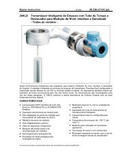
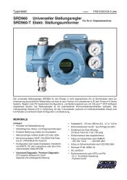
SRD991 Intelligent Positioner - FOXBORO ECKARDT
SRD991 Intelligent Positioner - FOXBORO ECKARDT
SRD991 Intelligent Positioner - FOXBORO ECKARDT

Create successful ePaper yourself
Turn your PDF publications into a flip-book with our unique Google optimized e-Paper software.
QG EVE0105 B-(en) <strong>SRD991</strong> 7<br />
Menustructure for <strong>SRD991</strong>/SRD960 with LCD<br />
SRD Main Menu<br />
Menu Factory Description<br />
configuration<br />
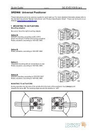
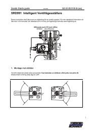
1 Mounting<br />
1.1 Lin left � Linear actuator, left-hand or direct mounting<br />
1.2 Lin right Linear actuator, right-hand mounting<br />
1.3 Rot cclockw Rotary actuator, opening counter-clockwise<br />
1.4 Rot clockw Rotary actuator, opening clockwise<br />
2 Autostart<br />
2.1 Endpoints Adaptation of the mechanical stops only<br />
2.2 Standard Autostart recommended for standard application<br />
2.3 Extended Extended Autostart, fast response with maybe overshoot<br />
2.4 Smooth resp. Extended Autostart, damped response to avoid overshoot<br />
2.5 Fast resp. Extended Autostart, very fast response with limited overshoot<br />
3 Valve Action<br />
3.1 SRD<br />
3.1.1 Direct � Valve opens with increasing setpoint value<br />
3.1.2 Reverse Valve closes with increasing setpoint value<br />
3.2 Feedback<br />
3.2.1 Direct � Increasing Current with increasing valve position<br />
3.2.2 Reverse Decreasing Current with increasing valve position<br />
4 Character<br />
4.1 Linear � Linear characteristic<br />
4.2 Eq Perc 1:50 Equal percentage characteristic 1:50<br />
4.3 Quick open Inverse equal percentage characteristic 1:50 (quick opening)<br />
4.4 Customer Custom characteristic<br />
5 Limits/alarms<br />
Not locally available with LED versions of communication FF and<br />
Profibus<br />
5.1 Lower limit 0 % Closing limit is set to input value<br />
5.2 Cutoff low 1 % 0%-tight sealing point is set to input value<br />
5.3 Cutoff high 100 % 100%-tight sealing point is set to input value<br />
5.4 Upper limit 100 % Opening limit is set to input value<br />
5.5 Splitr 0 % 4 mA Split range 0 %: input value corresponds to 0 %<br />
5.6 Splitr 100 % 20 mA Split range 100 %: input value corresponds to 100 %<br />
5.7 Lower Alarm -10 % Lower position alarm on output 1 is set to input value<br />
5.8 Upper Alarm 110 % Upper position alarm on output 2 is set to input value<br />
5.9 Valve 0% 4 mA Configuration of rated-stroke of 0% at 4 mA<br />
5.10 Valve 100% 20 mA Configuration of rated-stroke of 100% at 20 mA<br />
5.11 Stroke Range x° / 20mm Configuration of nominal travel<br />
5.12 Units SI Configuration of temperature and pressure unit SI or Anglo US<br />
6 Parameters<br />
6.1 Gain closing 15 P: Proportional gain for ‘close valve’<br />
6.2 Gain opening 2 P: Proportional gain for ‘open valve’<br />
6.3 Res time cl 7.5 I: Integration time for ‘close valve’<br />
6.4 Res time op 2.4 I: Integration time for ‘open valve’<br />
6.5 Rate lim cl 0.35 T63: Setting time for ‘close valve’<br />
6.6 Rate lim op 0.35 T63: Setting time for ‘open valve’<br />
6.7 Control gap 0.1 Permitted neutral zone for control difference<br />
7 Output Manual setting of IP-Module for testing of pneumatic output<br />
8 Setpoint Manual setting of valve position<br />
8.1 12.5% Steps Setpoint changes of 12.5% steps by using push buttons Up or Down<br />
8.2 1% Steps Setpoint changes of 1% steps by using push buttons Up or Down<br />
8.3 Do PST Start Partial Strok Test<br />
Continue on the next page...