Life science special report 161215 IY opt

You also want an ePaper? Increase the reach of your titles
YUMPU automatically turns print PDFs into web optimized ePapers that Google loves.
MANUFACTURING VACCINES LIFE SCIENCES<br />
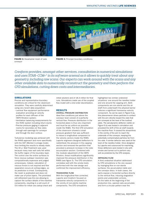
FIGURE 3: Hexahedral mesh of vials<br />
conveyor<br />
FIGURE 4: Principal boundary conditions<br />
Creaform provides, amongst other services, consultation in numerical simulations<br />
and uses STAR-CCM+ ® in its software arsenal as it allows to quickly treat about any<br />
geometry, including raw scans. Our experts can work around with the scans and any<br />
other available data to numerically reconstruct the geometry and then perform the<br />
CFD simulations, cutting down costs and intermediaries.<br />
SIMULATIONS<br />
Precise and representative boundary<br />
conditions are critical for the cleanroom<br />
simulation. They were carefully determined<br />
using very recent data acquisition:<br />
• Laminar flow equipment performance<br />
evaluation providing air velocity<br />
profiles for each diffuser of the<br />
HEPA filtration system;<br />
• Ventilation balancing measurements for<br />
the HVAC system including return ducts;<br />
• Precise pressure gaging in adjacent<br />
rooms for secondary air flow rates<br />
through wall openings for conveyor<br />
and through the door contour.<br />
Turbulence modeling was achieved with<br />
the RANS approach and more specifically<br />
with the SST (Menter) k-omega model,<br />
thus limiting the results to steady state.<br />
The All y+ Wall Treatment was used<br />
because many near wall cells fell within<br />
the buffer region of the boundary layer.<br />
The control over the entire surfaces to<br />
force viscous sublayer resolution was<br />
computationally expensive and judged<br />
unnecessary. Indeed, calculation of<br />
viscous forces is not required and flow<br />
separation occurs at cutting edges, so<br />
its prediction is trivial. Consequently,<br />
the mesh is polyhedral and does not<br />
make use of prism layers. The prioritized<br />
cell refinement was the one allowing to<br />
capture the surface details of the machine<br />
components, resulting in a cell count of<br />
5.6 million for initial runs (setup check and<br />
initial solution) and of 18.4 million for final<br />
runs. Simulations made use of the coupled<br />
flow model with a 2nd order discretization.<br />
RESULTS<br />
OVERALL PRESSURE DISTRIBUTION<br />
Ideal flow conditions just above the<br />
conveyor level consist of a perfectly<br />
vertical flow. Pressure distribution in the<br />
horizontal plane is thus very important<br />
and must be as uniform as possible<br />
inside the RABS. The first CFD simulation<br />
of the cleanroom showed a small<br />
pressure gradient that was sufficient<br />
to induce a longitudinal component to<br />
the velocity vectors inside the RABS.<br />
Laporte engineers designed deflectors to<br />
redistribute the pressure in the capping<br />
section and removed the partition that<br />
provoked a pressure increase in the vials<br />
accumulation section. Combined with<br />
the modular adjustment of the HEPA<br />
filtration, these modifications significantly<br />
improved the pressure distribution in the<br />
RABS (see figure 5). The CFD simulation<br />
correlates well with the smoke tests<br />
performed with the new design and<br />
confirmed the improvement efficiency.<br />
TRANSVERSE FLOW<br />
With the longitudinal flow corrected,<br />
Laporte and Creaform focused on<br />
transverse velocity components in<br />
the vicinity of non-sterile machine<br />
components. The CFD simulations<br />
highlighted two similar undesired<br />
situations: one around the needles holder<br />
and one around the capping arm. Both<br />
components are non-sterile and the air<br />
draft from underneath the physical barrier<br />
induces a significant transverse velocity<br />
component. As can be seen in Figure 6 (a),<br />
this phenomenon drives particles in contact<br />
with the arm directly toward the vials that<br />
are conveyed at the level of the toothed<br />
plate. The aerodynamic deflector visible on<br />
Figure 6 (b) was tested in simulation and<br />
provoked the shift of the air draft towards<br />
the machine floor. It caused the streamlines<br />
in the vicinity of the arm to reach the<br />
underside of the conveyor, keeping the<br />
potentially contaminated particles far from<br />
the vials. A similar defector was used at the<br />
level of the needles holder. Once designed<br />
by Laporte and outsourced for machining,<br />
these deflectors were tested in situ with<br />
smoke and turned out to perform very<br />
well as predicted by the CFD analysis.<br />
IMPINGING FLOW<br />
A third undesired situation addressed<br />
by CFD simulations is the one caused<br />
by impinging flow on non-sterile<br />
surfaces: the accumulation table and<br />
the conveyor discs. In both cases, the<br />
parts expose a horizontal surface directly<br />
to the vertical flow, inducing stagnation<br />
points and undesirable vortices.<br />
On the table at the beginning of the<br />
production line, opened vials accumulate<br />
and form a circular pattern near the<br />
SPECIAL REPORT<br />
35