Life science special report 161215 IY opt

Create successful ePaper yourself
Turn your PDF publications into a flip-book with our unique Google optimized e-Paper software.
LIFE SCIENCES DAMPER DESIGN<br />
By employing design parameters<br />
in STAR-CCM+ ® , design exploration<br />
and <strong>opt</strong>imization were carried out<br />
to produce the prototype with the<br />
desired performance in the first design<br />
iteration.<br />
FIGURE 1: System view showing the hand and the orthosis<br />
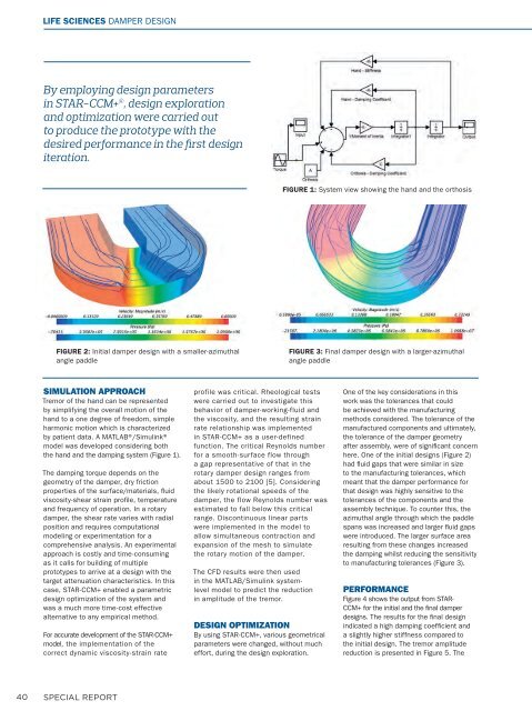
FIGURE 2: Initial damper design with a smaller-azimuthal<br />
angle paddle<br />
FIGURE 3: Final damper design with a larger-azimuthal<br />
angle paddle<br />
SIMULATION APPROACH<br />
Tremor of the hand can be represented<br />
by simplifying the overall motion of the<br />
hand to a one degree of freedom, simple<br />
harmonic motion which is characterized<br />
by patient data. A MATLAB®/Simulink®<br />
model was developed considering both<br />
the hand and the damping system (Figure 1).<br />
The damping torque depends on the<br />
geometry of the damper, dry friction<br />
properties of the surface/materials, fl uid<br />
viscosity-shear strain profi le, temperature<br />
and frequency of operation. In a rotary<br />
damper, the shear rate varies with radial<br />
position and requires computational<br />
modeling or experimentation for a<br />
comprehensive analysis. An experimental<br />
approach is costly and time-consuming<br />
as it calls for building of multiple<br />
prototypes to arrive at a design with the<br />
target attenuation characteristics. In this<br />
case, STAR-CCM+ enabled a parametric<br />
design <strong>opt</strong>imization of the system and<br />
was a much more time-cost effective<br />
alternative to any empirical method.<br />
For accurate development of the STAR-CCM+<br />
model, the implementation of the<br />
correct dynamic viscosity-strain rate<br />
profile was critical. Rheological tests<br />
were carried out to investigate this<br />
behavior of damper-working-fluid and<br />
the viscosity, and the resulting strain<br />
rate relationship was implemented<br />
in STAR-CCM+ as a user-defined<br />
function. The critical Reynolds number<br />
for a smooth-surface flow through<br />
a gap representative of that in the<br />
rotary damper design ranges from<br />
about 1500 to 2100 [5]. Considering<br />
the likely rotational speeds of the<br />
damper, the flow Reynolds number was<br />
estimated to fall below this critical<br />
range. Discontinuous linear parts<br />
were implemented in the model to<br />
allow simultaneous contraction and<br />
expansion of the mesh to simulate<br />
the rotary motion of the damper.<br />
The CFD results were then used<br />
in the MATLAB/Simulink systemlevel<br />
model to predict the reduction<br />
in amplitude of the tremor.<br />
DESIGN OPTIMIZATION<br />
By using STAR-CCM+, various geometrical<br />
parameters were changed, without much<br />
effort, during the design exploration.<br />
One of the key considerations in this<br />
work was the tolerances that could<br />
be achieved with the manufacturing<br />
methods considered. The tolerance of the<br />
manufactured components and ultimately,<br />
the tolerance of the damper geometry<br />
after assembly, were of signifi cant concern<br />
here. One of the initial designs (Figure 2)<br />
had fl uid gaps that were similar in size<br />
to the manufacturing tolerances, which<br />
meant that the damper performance for<br />
that design was highly sensitive to the<br />
tolerances of the components and the<br />
assembly technique. To counter this, the<br />
azimuthal angle through which the paddle<br />
spans was increased and larger fl uid gaps<br />
were introduced. The larger surface area<br />
resulting from these changes increased<br />
the damping whilst reducing the sensitivity<br />
to manufacturing tolerances (Figure 3).<br />
PERFORMANCE<br />
Figure 4 shows the output from STAR-<br />
CCM+ for the initial and the final damper<br />
designs. The results for the fi nal design<br />
indicated a high damping coeffi cient and<br />
a slightly higher stiffness compared to<br />
the initial design. The tremor amplitude<br />
reduction is presented in Figure 5. The<br />
40 SPECIAL REPORT