Life science special report 161215 IY opt

You also want an ePaper? Increase the reach of your titles
YUMPU automatically turns print PDFs into web optimized ePapers that Google loves.
LIFE SCIENCES MANUFACTURING VACCINES<br />
(a)<br />
(b)<br />
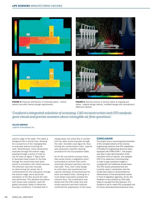
FIGURE 5: Pressure distribution in horizontal plane – before<br />
(above) and after (below) design adjustments<br />
FIGURE 6: Velocity vectors in section plane at capping arm<br />
elbow - original design (above), modified design with aerodynamic<br />
deflectors (below)<br />
"Creaform's integrated solutions of scanning, CAD reconstruction and CFD analysis<br />
gave visual and precise answers about intangible air flow questions."<br />
GILLES GRENON<br />
Laporte Consultants Inc.<br />
exterior edge of the table. This table is<br />
designed with a central hole, allowing<br />
for a proportion of the impinging flow<br />
to evacuate without touching the<br />
vials. Nevertheless, some streamlines<br />
evacuate through the exterior edge,<br />
passing through a series of vials as<br />
can be seen on figure 7. Many fixes<br />
to decrease head losses for the flow<br />
through the central hole have been<br />
tested in simulation with mixed success.<br />
The attention was then focused<br />
on determining the actual risk of<br />
contamination for the evacuation through<br />
the exterior edge, and a particular<br />
simulation of the flow around the vials<br />
was performed. This detailed simulation,<br />
with actual vials modeled, used the<br />
global simulation fields to determine<br />
boundary conditions. It showed that in<br />
steady-state, the entire flow in contact<br />
with the table would evacuate through<br />
the vials’ shoulders (see figure 8), thus<br />
limiting the contamination risks. Laporte<br />
also proposed a specific cleaning<br />
procedure for the accumulation table.<br />
As for the non-sterile conveyor discs,<br />
they would induce a stagnation point<br />
surrounded by vortices that would<br />
eventually transport particles over the<br />
vials path. Thus, their initial design<br />
as solid discs was questioned and<br />
Laporte ultimately remanufactured the<br />
discs and added holes, allowing for a<br />
much better evacuation towards the<br />
machine floor. The modification was<br />
tested with the CFD model and with<br />
smoke ejections and both methods<br />
confirmed the suppression of the issue.<br />
CONCLUSION<br />
The project was a convincing demonstration<br />
of the complementarity of the reverse<br />
engineering solutions and CFD capabilities<br />
of Creaform’s Engineering Services team,<br />
equipped with STAR-CCM+®. The project<br />
was also a clear demonstration of the<br />
innovative mind of Laporte, who ad<strong>opt</strong>ed<br />
CFD in its cleanroom commissioning<br />
in order to gain predictive insight to<br />
complement the traditional smoke tests.<br />
The CFD results presented here are<br />
currently used in combination with the<br />
smoke test videos to demonstrate the<br />
effectiveness of the aerodynamic barrier<br />
in front of regulatory agencies. So far, the<br />
feedback is very positive as CFD really<br />
helps to visualize the flow features. It is<br />
Creaform’s will to make CFD a prevalent tool<br />
for future pharmaceutical production lines.<br />
36 SPECIAL REPORT