C7400S Enthalpy Sylk Bus Sensor - CONTROL SOLUTIONS ...
C7400S Enthalpy Sylk Bus Sensor - CONTROL SOLUTIONS ...
C7400S Enthalpy Sylk Bus Sensor - CONTROL SOLUTIONS ...
Create successful ePaper yourself
Turn your PDF publications into a flip-book with our unique Google optimized e-Paper software.
<strong>C7400S</strong> <strong>Enthalpy</strong> <strong>Sylk</strong> <strong>Bus</strong> <strong>Sensor</strong><br />
PRODUCT DESCRIPTION<br />
The <strong>C7400S</strong> <strong>Sylk</strong> <strong>Bus</strong> sensor is a combination temperature<br />
and humidity sensor, which is intended to be used in<br />
commercial roof top units for sensing air. The sensor is<br />
powered by and communicates on the <strong>Sylk</strong> <strong>Bus</strong>. The <strong>C7400S</strong><br />
communicates temperature and humidity separately digitally<br />
on the <strong>Sylk</strong> <strong>Bus</strong> Communication Protocol.<br />
A separate controller such as the JADE Economizer<br />
System (Model W7220) provides power and communications<br />
on the <strong>Sylk</strong> <strong>Bus</strong> for the <strong>C7400S</strong> <strong>Sylk</strong> <strong>Bus</strong> sensor.<br />
SPECIFICATIONS<br />
Electrical<br />
Supply Voltage: 7 to 21 Vdc<br />
Power Consumption: 5 mA<br />
Output Rating: 75 ohm load switched at 9600 Baud<br />
Wiring: <strong>Sylk</strong> <strong>Bus</strong>: 2-wire (18 to 22 AWG)<br />
Environmental<br />
E4436<br />
INSTALLATION INSTRUCTIONS<br />
Operating Temperature range: -40 to 150 °F (-40 to 65 °C)<br />
Storage Temperature range: -40 to 150 °F (-40 to 65 °C)<br />
Shipping Temperature range: -40 to 150 °F (-40 to 65 °C)<br />
Operating Relative Humidity range: 5% to 95% RH noncondensing<br />
Temperature and Humidity, <strong>C7400S</strong>:<br />
Temperature sensing range: -40 to 150 °F (-40 to 65 °C)<br />
Humidity sensing range: 0 to 100% RH with 5% accuracy.<br />
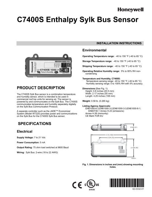
Dimensions (See Fig. 1):<br />
Height: 0.8 inches (20.5 mm)<br />
Width: 2.17 inches (55 mm)<br />
Length: 4.25 inches (108 mm)<br />
Weight: 0.58 lb. (0.265 kg)<br />
Listing Agency Approvals:<br />
EN61000-6-3,EN61000-3-2;EN61000-3-3;EN61000-6-1;<br />
EN60730-1 Annex H.23 (emissions)<br />
Annex H.26 (immunity)<br />
CE Mark FOR EU<br />
4-1/4 (108)<br />
2-3/4 (70)<br />
51/64 (21)<br />
2-1/64 (55)<br />
M32331<br />
Fig. 1. Dimensions in inches and (mm) showing mounting<br />
holes.<br />
62-0332-01
<strong>C7400S</strong> ENTHALPY SYLK BUS SENSOR<br />
BEFORE INSTALLATION<br />
Review the “Specifications” on page 1 before installing the<br />
sensor.<br />
When Installing This Product<br />
1. Read these instructions carefully. Failure to follow them<br />
could damage the product or cause a hazardous<br />
condition.<br />
2. Check ratings given in instructions and on the product to<br />
ensure the product is suitable for your application.<br />
3. Installer must be a trained, experienced service<br />
technician.<br />
INSTALLATION AND SETUP<br />
The following installation procedures should be performed in<br />
the order listed:<br />
1. Mounting — see “Mounting” on this page.<br />
2. Wiring — see “Wiring” on page 3.<br />
3. Checkout — see “Checkout” on page 3.<br />
MOUNTING<br />
IMPORTANT<br />
Avoid mounting in areas where acid fumes or other<br />
deteriorating vapors can attack the metal parts of the<br />
sensor, or in areas where escaping gas or other<br />
explosive vapors are present.<br />
IMPORTANT<br />
The sensor must be mounted in a position that<br />
allows clearance for wiring, servicing, and removal.<br />
The sensor is mounted directly to the sheet metal using self<br />
tapping sheet metal screws or in the air stream using the duct<br />
mounting kit. Use #6 or #8 screws (screws are not provided<br />
and must be obtained separately). Use the dimensions in<br />
Fig. 1 on page 1 as a guide.<br />
The sensor must be mounted to allow air flow through the<br />
sensor housing vent slots on the end or side.<br />
The <strong>Sylk</strong> <strong>Bus</strong> sensor communicates with a controller (such as<br />
the JADE Economizer Model W7220) on the two-wire<br />
communication bus and can either be wired using a two pin<br />
header or using a side connector. The unit pack <strong>Sylk</strong> <strong>Bus</strong><br />
sensor includes a two pin Euro connector with the packaging.<br />
The SKU number of the <strong>Sylk</strong> <strong>Bus</strong> sensor is <strong>C7400S</strong>. All OAT<br />
(Outdoor Air Temperature), RAT (Return Air Temperature) and<br />
DAT (Discharge Air Temperature) sensors are the same SKU<br />
number. The sensor is set for the appropriate type of sensing<br />
using the three position DIP switch located on the sensor.<br />
OAT position is OFF, OFF, OFF; RAT is ON, OFF, OFF and<br />
DAT is OFF, ON, OFF. During installation the sensors are set<br />
for the the appropriate usage. See “<strong>Sylk</strong> <strong>Bus</strong> <strong>Sensor</strong> Wiring”<br />
on page 3 for DIP switch details.<br />
62-0332—01 2<br />
Once installed, a sensor can be changed to a different<br />
application by simply changing the DIP switch setting.<br />
<strong>Sensor</strong> Mounting<br />
The sensor can be mounted directly on to the sheet metal of<br />
the unit or can be mounted in the air stream using the duct<br />
mounting kit.<br />
The duct mounting kit contains a rod to hold the sensor in the<br />
duct, a flange to secure the sensor rod to the duct wall and to<br />
fill the hole, and a gasket to prevent air from leaking through<br />
the duct wall. See Fig. 2.<br />
The rod has slots for threading the wire to prevent loose or<br />
hanging wire in the duct and can be adjusted for 6 or 12 inch<br />
length. The flange has extended relief for ease of mounting.<br />
See Fig. 3.<br />
50048194-001<br />
(ROD) 1 PIECE<br />
50048196-001<br />
(GASKET) 1 PIECE<br />
50048195-001<br />
(FLANGE) 1 PIECE<br />
Fig. 2. Duct Mounting Components.<br />
WIRE HOLDER<br />
LENGTH ADJUSTS<br />
TO 6 OR 12 INCHES<br />
EXTENDED RELIEF<br />
(FOR CORRECT MOUNTING) M32282<br />
Fig. 3. Duct Mounting Adjustments.<br />
M32281
WIRING<br />
All wiring must comply with applicable electrical codes and<br />
ordinances, or as specified on installation wiring diagrams.<br />
WARNING<br />
Electrical Shock Hazard.<br />
Can cause severe injury, death or property<br />
damage.<br />
Disconnect power supply before beginning wiring, or<br />
making wiring connections, to prevent electrical shock<br />
or equipment damage.<br />
CAUTION<br />
Equipment Damage Hazard.<br />
Electrostatic discharge can short equipment<br />
circuitry.<br />
Ensure that you are properly grounded before<br />
handling the sensor.<br />
Prepare wiring as follows:<br />
1. Strip 1/2 in. (13 mm) insulation from the conductor.<br />
2. Cut a single wire to 3/16 in. (5 mm). Insert the wire in<br />
the required terminal location and tighten the screw.<br />
3. Pull on each wire in all terminals to check for good<br />
mechanical connection.<br />
<strong>Sylk</strong> <strong>Bus</strong> <strong>Sensor</strong> Wiring<br />
Use Fig. 4 and Table 1 to locate the wiring terminals for each<br />
<strong>Sylk</strong> <strong>Bus</strong> sensor.<br />
Use Fig. 4 and Table 2 to set the DIP switches for the desired<br />
use of the sensor.<br />
SYLK BUS<br />
TERMINALS<br />
(1 AND 2)<br />
DIP<br />
SWITCH<br />
LABEL<br />
DIP<br />
SWITCHES<br />
(3)<br />
SYLK BUS<br />
2 PIN “EURO”<br />
CONNECTOR<br />
M32271<br />
Fig. 4. <strong>Sylk</strong> <strong>Bus</strong> sensor DIP switches.<br />
a Terminals are polarity insensitive.<br />
CHECKOUT<br />
<strong>C7400S</strong> ENTHALPY SYLK BUS SENSOR<br />
Table 1. SYLK <strong>Bus</strong> <strong>Sensor</strong> Wiring Terminations a .<br />
Terminal<br />
Nbr Label Type Description<br />
1 S-BUS SYLK <strong>Bus</strong> <strong>Sylk</strong> <strong>Bus</strong> Communications<br />
(<strong>Sensor</strong> <strong>Bus</strong>)<br />
2 S-BUS SYLK <strong>Bus</strong> <strong>Sylk</strong> <strong>Bus</strong> Communications<br />
(<strong>Sensor</strong> <strong>Bus</strong>)<br />
Table 2. SYLK <strong>Bus</strong> <strong>Sensor</strong> DIP Switch Settings.<br />
Use<br />
DAa RA b<br />
OAc DIP Switch Positions for Switches 1, 2, & 3<br />
1 2 3<br />
a<br />
DA = Discharge Air<br />
b<br />
RA = Return Air<br />
c<br />
OA = Outside Air<br />
OFF ON OFF<br />
ON OFF OFF<br />
OFF OFF OFF<br />
Refer to the JADE Economizer Module (Model W7220)<br />
Installation Instructions (Honeywell form 62-0331).<br />
TROUBLESHOOTING<br />
Refer to the JADE Economizer Module (Model W7220)<br />
Installation Instructions (Honeywell form 62-0331).<br />
3 62-0332—01
<strong>C7400S</strong> ENTHALPY SYLK BUS SENSOR<br />
JADE is a trademark of Honeywell, Inc.<br />
Automation and Control Solutions<br />
Honeywell International Inc.<br />
1985 Douglas Drive North<br />
Golden Valley, MN 55422<br />
Honeywell Limited-Honeywell Limitée<br />
35 Dynamic Drive<br />
Toronto, Ontario M1V 4Z9<br />
customer.honeywell.com<br />
® U.S. Registered Trademark<br />
© 2010 Honeywell International Inc.<br />
62-0332—01 M.S. 09-10<br />
Printed in U.S.A.


