NXS Form 63-2600, Users Manual, Technical Data - CONTROL ...
NXS Form 63-2600, Users Manual, Technical Data - CONTROL ...
NXS Form 63-2600, Users Manual, Technical Data - CONTROL ...
- No tags were found...

Create successful ePaper yourself
Turn your PDF publications into a flip-book with our unique Google optimized e-Paper software.
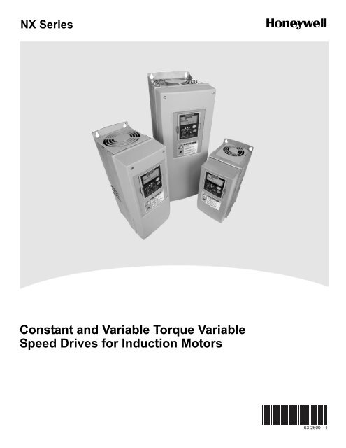
NX Series<br />
Constant and Variable Torque Variable<br />
Speed Drives for Induction Motors<br />
<strong>63</strong>-<strong>2600</strong>—1
REFER TO THE START-UP QUICK GUIDE BELOW DURING INSTALLATION AND COMMISSIONING.<br />
IF ANY PROBLEMS OCCUR, PLEASE CONTACT YOUR LOCAL DISTRIBUTOR.<br />
Start-up Quick Guide<br />
1. Check that the delivery corresponds to your order, see Chapter 3.<br />
2. Before taking any commissioning actions read carefully the safety instructions in Chapter<br />
1.<br />
3. Before the mechanical installation, check the minimum clearances around the unit and<br />
check the ambient conditions in Chapter 5.<br />
4. Check the size of the motor cable, mains cable, mains fuses and check the cable<br />
connections, read Chapters 6.1.1.1 to 6.1.1.5..<br />
5. Follow the installation instructions, see Chapter 6.1.5.<br />
6. Control connections are explained in Chapter 6.2.1.<br />
7. If the Start-Up wizard is active, select the language of the keypad and the application<br />
you want to use and confirm by pressing the Enter button. If the Start-Up wizard is not<br />
active, follow the instructions 7a and 7b.<br />
7a. Select the language of the keypad from the Menu M6, page 6.1. Instructions on using<br />
the keypad are given in Chapter 7.<br />
7b. Select the application you want to use from the Menu M6, page 6.2. Instructions on<br />
using the keypad are given in Chapter 7.<br />
8. All parameters have factory default values. In order to ensure proper operation, check<br />
the rating plate data for the values below and the corresponding parameters of<br />
parameter group G2.1.<br />
• nominal voltage of the motor<br />
• nominal frequency of the motor<br />
• nominal speed of the motor<br />
• nominal current of the motor<br />
• motor cosϕ<br />
All parameters are explained in the All in One Application <strong>Manual</strong>.<br />
9. Follow the commissioning instructions, see Chapter 8.<br />
10. NX_ Frequency Drive is now ready for use.<br />
The Manufacturer is not responsible for the use of the frequency drives<br />
outside the instructions provided.
CONTENTS<br />
NX USER’S MANUAL<br />
INDEX<br />
1 SAFETY<br />
2 EU DIRECTIVE<br />
3 RECEIPT OF DELIVERY<br />
4 TECHNICAL DATA<br />
5 INSTALLATION<br />
6 CABLING AND CONNECTIONS<br />
7 <strong>CONTROL</strong> KEYPAD<br />
8 COMMISSIONING<br />
9 FAULT TRACING
THE NX FREQUENCY DRIVE USER'S MANUAL<br />
AND THE APPLICATION MANUAL<br />
The User's <strong>Manual</strong> will provide the necessary information about the installation, commissioning<br />
and operation of NX Frequency Drives. It is recommended that these instructions are studied,<br />
before powering up the frequency drive for the first time.<br />
The Application <strong>Manual</strong> provides information about the different applications included in the<br />
standard frequency drive. Should these applications not meet the requirements of the process,<br />
contact Honeywell for information on special applications.<br />
This manual is available in both paper and electronic editions. It is recommended that the<br />
electronic version be used where possible as it contains several links and cross-references to<br />
other locations in the manual which makes it easier for the reader to move around in the manual,<br />
to check and find things faster.
NX User's <strong>Manual</strong><br />
Index<br />
1. SAFETY....................................................................................................................................6<br />
1.1 WARNINGS..............................................................................................................................................6<br />
1.2 SAFETY INSTRUCTIONS............................................................................................................................6<br />
1.3 GROUNDING AND GROUND FAULT PROTECTION.........................................................................................7<br />
1.4 RUNNING THE MOTOR..............................................................................................................................7<br />
2. DIRECTIVES.............................................................................................................................8<br />
2.1 CE MARKING...........................................................................................................................................8<br />
2.2 EMC DIRECTIVE......................................................................................................................................8<br />
2.2.1 General...............................................................................................................................................8<br />
2.2.2 <strong>Technical</strong> criteria ................................................................................................................................8<br />
2.2.3 NX frequency drive EMC classification...............................................................................................8<br />
2.2.4 Manufacturer's declaration of conformity............................................................................................9<br />
2.3 UL-LABEL................................................................................................................................................9<br />
3. RECEIPT OF SHIPMENT .......................................................................................................13<br />
3.1 TYPE DESIGNATION CODE ......................................................................................................................13<br />
3.2 STORAGE..............................................................................................................................................13<br />
3.3 MAINTENANCE.......................................................................................................................................14<br />
3.4 WARRANTY ...........................................................................................................................................14<br />
4. TECHNICAL DATA ................................................................................................................15<br />
4.1 INTRODUCTION......................................................................................................................................15<br />
4.2 POWER RATINGS ...................................................................................................................................17<br />
4.2.1 NX_5 – Mains voltage 380—500 V ..................................................................................................17<br />
4.2.2 NX_6 – Mains voltage 525—690 V ..................................................................................................18<br />
4.2.3 NX_2 – Mains voltage 208—240 V ..................................................................................................19<br />
4.3 BRAKE RESISTOR RATINGS ....................................................................................................................20<br />
4.4 TECHNICAL DATA...................................................................................................................................22<br />
5. INSTALLATION......................................................................................................................24<br />
5.1 MOUNTING ............................................................................................................................................24<br />
5.2 COOLING...............................................................................................................................................34<br />
5.2.1 FR4 to FR9 .......................................................................................................................................34<br />
5.2.2 Standalone units (FR10 to FR12).....................................................................................................35<br />
5.3 POWER LOSS ........................................................................................................................................36<br />
5.3.1 Power loss as function of switching frequency .................................................................................36<br />
6. CABLING AND CONNECTIONS............................................................................................40<br />
6.1 POWER UNIT .........................................................................................................................................40<br />
6.1.1 Power connections ...........................................................................................................................40<br />
6.1.1.1 Mains and motor cables ................................................................................................................40<br />
6.1.1.2 DC supply and brake resistor cables.............................................................................................41<br />
6.1.1.3 Control cable .................................................................................................................................41<br />
6.1.1.4 Cable and fuse sizes, <strong>NXS</strong> B and <strong>NXS</strong> A......................................................................................41<br />
6.1.1.5 Cable and fuse sizes, <strong>NXS</strong> C ........................................................................................................42<br />
6.1.1.6 Cable and fuse sizes, NX_A, FR10 to FR12 .................................................................................42<br />
6.1.1.7 Cable and fuse sizes, NX_C, FR10 to FR12 .................................................................................43<br />
6.1.2 Understanding the power unit topology ............................................................................................43<br />
6.1.3 Changing EMC protection class from H to T ....................................................................................44
6.1.4 Mounting of cable accessories .........................................................................................................46<br />
6.1.5 Installation instructions .....................................................................................................................48<br />
6.1.5.1 Stripping lengths of motor and mains cables.................................................................................50<br />
6.1.5.2 NX frequency drive frames and installation of cables....................................................................51<br />
6.1.6 Cable installation and the UL standards...........................................................................................58<br />
6.1.7 Cable and motor insulation checks...................................................................................................59<br />
6.2 <strong>CONTROL</strong> UNIT ......................................................................................................................................60<br />
6.2.1 <strong>NXS</strong> and NXP single phase input applications 380-500 VAC ..........................................................61<br />
6.2.2 Control connections..........................................................................................................................62<br />
6.2.2.1 Control cables................................................................................................................................<strong>63</strong><br />
6.2.2.2 Galvanic isolation barriers .............................................................................................................<strong>63</strong><br />
6.2.3 Control terminal signals ....................................................................................................................65<br />
6.2.3.1 Digital input signal inversions ........................................................................................................66<br />
6.2.3.2 Jumper selections on the OPT-A1 basic board .............................................................................67<br />
7. <strong>CONTROL</strong> KEYPAD ..............................................................................................................69<br />
7.1 INDICATIONS ON THE KEYPAD DISPLAY ...................................................................................................69<br />
7.1.1 Drive status indications.....................................................................................................................69<br />
7.1.2 Control place indications ..................................................................................................................70<br />
7.1.3 Status LEDs (green – green – red)...................................................................................................70<br />
7.1.4 Text lines ..........................................................................................................................................71<br />
7.2 KEYPAD PUSH-BUTTONS........................................................................................................................72<br />
7.2.1 Button descriptions ...........................................................................................................................72<br />
7.3 NAVIGATION ON THE <strong>CONTROL</strong> KEYPAD ..................................................................................................73<br />
7.3.1 Monitoring menu (M1) ......................................................................................................................75<br />
7.3.2 Parameter menu (M2) ......................................................................................................................76<br />
7.3.3 Keypad control menu (M3) ...............................................................................................................78<br />
7.3.3.1 Selection of control place ..............................................................................................................78<br />
7.3.3.2 Keypad reference ..........................................................................................................................79<br />
7.3.3.3 Keypad direction............................................................................................................................79<br />
7.3.3.4 Stop button activated.....................................................................................................................79<br />
7.3.4 Active faults menu (M4)....................................................................................................................80<br />
7.3.4.1 Fault types .....................................................................................................................................81<br />
7.3.4.2 Fault codes....................................................................................................................................82<br />
7.3.4.3 Fault time data record....................................................................................................................84<br />
7.3.5 Fault history menu (M5)....................................................................................................................85<br />
7.3.6 System menu (M6) ...........................................................................................................................86<br />
7.3.6.1 Language selection .......................................................................................................................89<br />
7.3.6.2 Application selection......................................................................................................................89<br />
7.3.6.3 Parameter copy .............................................................................................................................90<br />
7.3.6.4 Parameter comparison ..................................................................................................................92<br />
7.3.6.5 Security..........................................................................................................................................93<br />
7.3.6.6 Keypad settings .............................................................................................................................95<br />
7.3.6.7 Hardware settings..........................................................................................................................96<br />
7.3.6.8 System info....................................................................................................................................99<br />
7.3.7 Expander board menu (M7)............................................................................................................103<br />
7.4 FURTHER KEYPAD FUNCTIONS .............................................................................................................104<br />
8. COMMISSIONING ................................................................................................................105<br />
8.1 SAFETY...............................................................................................................................................105<br />
8.2 COMMISSIONING OF THE FREQUENCY DRIVE.........................................................................................105<br />
9. FAULT TRACING .................................................................................................................108
1<br />
6(110) Safety<br />
1. SAFETY<br />
ONLY A COMPETENT ELECTRICIAN SHOULD CARRY OUT<br />
THE ELECTRICAL INSTALLATION<br />
1.1 Warnings<br />
WARNING<br />
1<br />
The NX frequency drive is meant for fixed installations only.<br />
2<br />
Do not perform any measurements when the frequency drive is<br />
connected to the mains. The motor terminals U, V, W and the DClink/brake<br />
resistor terminals –/+ are live when the NX is connected to<br />
mains, even if the motor is not running.<br />
3<br />
Do not perform any voltage withstand tests on any part of the NX.<br />
4<br />
The frequency drive has a large capacitive leakage current.<br />
5<br />
If the frequency drive is used as a part of a machine, the machine<br />
manufacturer is responsible for providing the machine with a main switch<br />
(EN 60204-1).<br />
6<br />
Only spare parts delivered by Honeywell can be used.<br />
7<br />
The motor starts at power-up if the start command is 'ON'. Furthermore,<br />
the I/O functionalities (including start inputs) may change if parameters,<br />
applications or software are changed. Disconnect, therefore, the motor if<br />
an unexpected start can cause danger.<br />
8<br />
Prior to measurements on the motor or the motor cable, disconnect the<br />
motor cable from the frequency drive.<br />
9<br />
Do not touch the IC-circuits on the circuit boards. Static voltage discharge<br />
may damage the components.<br />
1.2 Safety instructions<br />
1<br />
The components of the power unit of the frequency drive are live when<br />
the NX is connected to mains potential. ontact with this voltage is<br />
extremely dangerous and may cause death or severe injury. The<br />
control unit is isolated from the potential.<br />
2<br />
The motor terminals U, V, W and the DC-link/brake resistor terminals –/+<br />
are live when the NX is connected to mains, even if the motor is not<br />
running.<br />
3<br />
After disconnecting the frequency drive from the mains, wait until the fan<br />
stops and the indicators on the keypad extinguish. (if no keypad is<br />
attached see the indicators on the cover). Wait 5 more minutes before<br />
doing any work on the NX connections. Do not even open the cover<br />
before this time has expired.<br />
4<br />
The control I/O-terminals are isolated from the mains potential. However,<br />
the relay outputs and other I/O-terminals may have a dangerous control<br />
voltage present even when the NX is disconnected from mains.<br />
5<br />
Before connecting the frequency drive to mains, ensure that the<br />
frequency drive front and cable covers are closed.
Safety 7(110)<br />
1<br />
1.3 Grounding and ground fault protection<br />
The NX frequency drive must always be grounded via a conductor connected to the grounding<br />
terminal .<br />
The ground fault protection inside the frequency drive protects only the drive itself against ground<br />
faults in the motor or the motor cable.<br />
If fault current protective switches (e.g. RCD or Ground Leakage devices) are to be used in<br />
conjunction with the frequency drive, they must be tested with ground fault currents that are<br />
possible to arise in fault situations.<br />
1.4 Running the motor<br />
Warning symbols<br />
For your own safety please pay special attention to the instructions marked with the following<br />
symbols:<br />
= Dangerous voltage<br />
WARNING<br />
= General warning<br />
HOT SURFACE<br />
= Hot surface – Risk of burn<br />
MOTOR RUN CHECK LIST<br />
1<br />
Before starting the motor, check that the motor is mounted properly<br />
and ensure that the machine connected to the motor allows the<br />
motor to be started.<br />
2<br />
Set the maximum motor speed (frequency) according to the motor<br />
and the machine connected to it.<br />
3<br />
Before reversing the motor shaft rotation direction make sure that<br />
WARNING this can be done safely.<br />
4<br />
Ensure that no power correction capacitors are connected to the<br />
motor cable.<br />
5<br />
Ensure that the motor terminals are not connected to mains<br />
potential.
8(110) DIRECTIVES<br />
2. DIRECTIVES<br />
2.1 CE marking<br />
The CE marking on the product guarantees the free movement of the product within the EEA<br />
(European Economic Area). It also guarantees that the product meets the various requirements<br />
defined by the directive.<br />
The NX frequency drives carry the CE label as a proof of compliance with the Low Voltage<br />
Directive (LVD) and the Electro Magnetic Compatibility (EMC). The company SGS FIMKO has<br />
acted as the Competent Body.<br />
2.2 EMC directive<br />
2.2.1 General<br />
The EMC Directive provides that the electrical apparatus must not excessively disturb the<br />
environment it is used in, and also, it shall have an adequate level of immunity toward other<br />
disturbances from the same environment.<br />
The compliance of the NX frequency drives with the EMC directive is verified with <strong>Technical</strong><br />
Construction Files (TCF) checked and approved by SGS FIMKO, which is a Competent Body. The<br />
<strong>Technical</strong> Construction Files are used to authenticate the comformity of the NX frequency drives<br />
with the Directive due to the large product family & variety of installations possibilities.<br />
2.2.2 <strong>Technical</strong> criteria<br />
The NX frequency drives are marketed throughout the world, a fact which makes the EMC<br />
requirements of customers different. As far as the immunity is concerned, all NX frequency drives<br />
are designed to fulfil even the strictest requirements, while as regards the emission level, the<br />
customer may want to upgrade the NX's already high ability to filter electro-magnetic<br />
disturbances.<br />
2.2.3 NX frequency drive EMC classification<br />
The NX frequency drives are divided into three classes, according to the level of electromagnetic<br />
disturbances emitted. There is no difference in the functions or the control electronics between<br />
these classes but their EMC properties vary as follows:<br />
Class H:<br />
NX_5 frequency drives (FR4 to FR9) and NX_2 frequency drives (FR4 to FR6) have been<br />
designed to fulfil the requirements of the product standard IEC 61800-3+A11 for the 1st<br />
environment restricted distribution and the 2nd environment.<br />
The emission levels correspond to the requirements of IEC 61000-6-4.<br />
Class L (NX_5, FR10 only):<br />
Provides filtering for the 2 nd environment, restricted distribution according to IEC 61800-3+A11.<br />
2
DIRECTIVES 9(110)<br />
Class T:<br />
The T-class drives have a small ground current and can be used with IT supplies only. If they are<br />
used with other supplies no EMC requirements are complied with.<br />
Class N:<br />
The drives of this class do not provide EMC emission protection. This kind of drives are mounted<br />
in enclosures.<br />
All NX frequency drives fulfil all EMC immunity requirements (standards IEC 61000-6-1,<br />
61000-6-2 and IEC 61800-3+A11).<br />
Warning: This is a product of the restricted sales distribution class according to IEC 61800-<br />
3. In a domestic environment this product may cause radio interference in which case the<br />
user may be required to take adequate measures.<br />
Note: For changing the EMC protection class of your NX frequency drive from class H to class T,<br />
please refer to the instructions given in Chapter 6.3.1.<br />
2.2.4 Manufacturer's declaration of conformity<br />
The following pages present the photocopies of the Manufacturer's Declarations of Conformity<br />
assuring the compliance of the NX frequency drives with the EMC-directives.<br />
2.3 UL-label<br />
The NX frequency drives are UL-listed according to the standards, based on the needed voltage<br />
and power range. For more information contact you local Honeywell distributor. More information<br />
of cable selection and installation can be found from chapter 5 and 6.<br />
2
10(110) DIRECTIVES<br />
We<br />
Manufacturer's name:<br />
EU DECLARATION OF CONFORMITY<br />
Vacon Oyj<br />
Manufacturer's address: P.O.Box 25<br />
Runsorintie 7<br />
FIN-65381 Vaasa<br />
Finland<br />
hereby declare that the product<br />
Product name:<br />
Model designation:<br />
<strong>NXS</strong>/P Frequency converter<br />
<strong>NXS</strong>/P 0003 5…. to 0520 5….<br />
has been designed and manufactured in accordance with the following<br />
standards:<br />
Safety: EN50178 (1997), EN60204-1 (1996)<br />
EN 60950 (3rd edition 2000, as relevant)<br />
EMC: EN61800-3 (1996)+A11(2000), EN 61000-6-2<br />
(1999), EN 61000-6-4 (2001)<br />
and conforms to the relevant safety provisions of the Low Voltage Directive<br />
(73/23/EEC) as amended by the Directive (93/68/EEC) and EMC Directive<br />
89/336/EEC.<br />
It is ensured through internal measures and quality control that the product<br />
conforms at all times to the requirements of the current Directive and the<br />
relevant standards.<br />
In Vaasa, 5th of May, 2003<br />
Vesa Laisi<br />
President<br />
The year the CE marking was affixed: 2002<br />
2
Receipt of shipment 11(110)<br />
3<br />
We<br />
Manufacturer's name:<br />
EU DECLARATION OF CONFORMITY<br />
Vacon Oyj<br />
Manufacturer's address: P.O.Box 25<br />
Runsorintie 7<br />
FIN-65381 Vaasa<br />
Finland<br />
hereby declare that the product<br />
Product name:<br />
<strong>NXS</strong>/P Frequency converter<br />
Model designation:<br />
<strong>NXS</strong>/P 0004 6…. to 0416 6….<br />
has been designed and manufactured in accordance with the following<br />
standards:<br />
Safety: EN50178 (1997), EN60204-1 (1996)<br />
EN 60950 (3rd edition 2000, as relevant)<br />
EMC: EN61800-3 (1996)+A11(2000), EN 61000-6-2<br />
(1999), EN 61000-6-4 (2001)<br />
and conforms to the relevant safety provisions of the Low Voltage Directive<br />
(73/23/EEC) as amended by the Directive (93/68/EEC) and EMC Directive<br />
89/336/EEC.<br />
It is ensured through internal measures and quality control that the product<br />
conforms at all times to the requirements of the current Directive and the<br />
relevant standards.<br />
In Vaasa, 17th of November, 2003<br />
Vesa Laisi<br />
President<br />
The year the CE marking was affixed: 2003
3<br />
12(110) Receipt of shipment<br />
We<br />
Manufacturer's name:<br />
EU DECLARATION OF CONFORMITY<br />
Vacon Oyj<br />
Manufacturer's address: P.O.Box 25<br />
Runsorintie 7<br />
FIN-65381 Vaasa<br />
Finland<br />
hereby declare that the product<br />
Product name:<br />
<strong>NXS</strong>/P Frequency converter<br />
Model designation:<br />
<strong>NXS</strong>/P 0003 2…. to 0114 2….<br />
has been designed and manufactured in accordance with the following<br />
standards:<br />
Safety: EN50178 (1997), EN60204-1 (1996)<br />
EN 60950 (3rd edition 2000, as relevant)<br />
EMC: EN61800-3 (1996)+A11(2000), EN 61000-6-2<br />
(1999), EN 61000-6-4 (2001)<br />
and conforms to the relevant safety provisions of the Low Voltage Directive<br />
(73/23/EEC) as amended by the Directive (93/68/EEC) and EMC Directive<br />
89/336/EEC.<br />
It is ensured through internal measures and quality control that the product<br />
conforms at all times to the requirements of the current Directive and the<br />
relevant standards.<br />
In Vaasa, 10th of November, 2003<br />
Vesa Laisi<br />
President<br />
The year the CE marking was affixed: 2003<br />
Note: Ask factory for other possible installation combinations.
Receipt of shipment 13(110)<br />
3<br />
3. RECEIPT OF SHIPMENT<br />
The NX frequency drives have undergone rigorous tests and quality checks at the factory before<br />
delivery. However, after unpacking the product, check that no signs of transport damages are to<br />
be found on the product and that the delivery is complete (compare the type designation of the<br />
product to the code below, Figure 3-1.<br />
Should the drive have been damaged during the shipping, contact the carrier and or distributor.<br />
If the delivery does not correspond to your order, contact the supplier immediately.<br />
In the small plastic bag included in the delivery you will find a silver Drive modified sticker. The<br />
purpose of the sticker is to notify the service personnel about the modifications made in the<br />
frequency drive. Attach the sticker on the side of the frequency drive to avoid losing it. Should the<br />
frequency drive be later modified (option board added, IP or EMC protection level changed), mark<br />
the change in the sticker.<br />
3.1 Type designation code<br />
N X S 0 0 5 0 B 1 2<br />
E n c l osure 00 Open chassis<br />
10 Nema 1<br />
12 Nema 12<br />
V o l t a ge range B 208-240 Vac 3 p h a s e<br />
A 380-500 Vac 3 p h a s e<br />
C 525-690 Vac 3 p h a s e<br />
M o t or Power (HP) 0005 1/2 HP<br />
L o w overloadability: 0050 5 HP<br />
1 0 % overload at 0400 40 HP e t c<br />
1 0 4 deg F<br />
Figure 3-1. NX type designation code<br />
P r o duct Series<br />
<strong>NXS</strong><br />
NXL<br />
3.2 Storage<br />
If the frequency drive is to be kept in store ensure that the ambient conditions are acceptable:<br />
Storing temperature -40…+158°F (-40…70° C)<br />
Relative humidity
3<br />
14(110) Receipt of shipment<br />
3.3 Maintenance<br />
In normal conditions, the NX frequency drives are maintenance-free. However, it is recommended<br />
the heatsink be cleared periodically with compressed air. The cooling fan can easily be changed if<br />
necessary.<br />
It may also be necessary to check the tightening torques of terminals at regular intervals.<br />
3.4 Warranty<br />
Only manufacturing defects are covered by the warranty. The manufacturer assumes no<br />
responsibility for damages caused during or resulting from transport, receipt of the delivery,<br />
installation, commissioning or use.<br />
The manufacturer shall in no event and under no circumstances be held responsible for damages<br />
and failures resulting from misuse, incorrect installation, unacceptable ambient temperature, dust,<br />
corrosive substances or operation outside the rated specifications.<br />
Neither can the manufacturer be held responsible for consequential damages.<br />
The Manufacturer's period of warranty is 18 months from the delivery or 12 months from the<br />
commissioning whichever expires first.<br />
The local distributor may grant a warranty time different from the above. This warranty period shall<br />
be specified in the distributor's sales and warranty terms. The manufacturer assumes no<br />
responsibility for warranties offered by others. With all warranty issues, please contact the<br />
distributor first.
<strong>Technical</strong> data 15(110)<br />
4. TECHNICAL DATA<br />
4.1 Introduction<br />
Figure 4-1 presents the block diagram of the NX frequency drive. The frequency drive consists of<br />
two units, the Power Unit and the Control Unit.<br />
The three-phase AC-choke (1) at the mains end together with the DC-link capacitor (2) form an<br />
LC-filter, which, again, together with the diode bridge produce the DC-voltage supply to the IGBT<br />
Inverter Bridge (3) block. The AC-choke also functions as a filter against High Frequency<br />
disturbances from the mains as well as against those caused by the frequency drive to the mains.<br />
It, in addition, enhances the waveform of the input current to the frequency drive. The entire power<br />
drawn by the frequency drive from the mains is active power.<br />
The IGBT Inverter Bridge produces a symmetrical, 3-phase PWM-modulated AC-voltage to the<br />
motor.<br />
The Motor and Application Control Block is based on microprocessor software. The<br />
microprocessor controls the motor basing on the information it receives through measurements,<br />
parameter settings, control I/O and control keypad. The motor and application control block<br />
controls the motor control ASIC which, in turn, calculates the IGBT positions. Gate drivers amplify<br />
these signals for driving the IGBT inverter bridge.<br />
Power<br />
module<br />
Brake resistor*<br />
Mains<br />
L1<br />
L2<br />
L3<br />
1)<br />
Integrated input module<br />
Rectifier<br />
3~<br />
=<br />
Charg.res.<br />
Brake<br />
Chopper*<br />
2)<br />
3)<br />
IGBT<br />
Inverter Current<br />
Sensors<br />
=<br />
3~<br />
Motor<br />
U Output<br />
V EMCfilter<br />
W<br />
Fan<br />
Power<br />
Supply<br />
Measurements<br />
Gate<br />
Drivers<br />
Voltage<br />
Sensors<br />
NXP<br />
Control<br />
Keypad<br />
Control<br />
module<br />
Motor and<br />
Application<br />
Control<br />
Motor<br />
Control<br />
ASIC<br />
Control<br />
I/O<br />
Control<br />
I/O<br />
Control<br />
I/O<br />
Control<br />
I/O<br />
Control<br />
I/O<br />
*The brake resistor can be installed internally in classes FR4 to FR6 (NX_2 and NX_5). In all other<br />
frames of voltage classes NX_2 and NX_5, as well as in all frames of all other voltage classes, the<br />
brake resistor is available as option and installed externally.<br />
Brake chopper belongs to the standard equipment in classes FR4 to FR6, while in greater classes<br />
(FR7 to FR9) it is optional.<br />
Figure 4-1. NX block diagram<br />
Automation and Control Solutions<br />
Honeywell<br />
Honeywell Limited-Honeywell Limitée<br />
1985 Douglas Drive North 35 Dynamic Drive<br />
Golden Valley, MIN 55422 Scarborough, Ontario <strong>63</strong>-<strong>2600</strong>-1<br />
MIV 4Z9<br />
www.honeywell.com<br />
4
16(110) <strong>Technical</strong> data<br />
The control keypad provides a link between the user and the frequency drive. The control keypad<br />
is used for parameter setting, reading status data and giving control commands. It is detachable<br />
and can be operated externally and connected via a cable to the frequency drive. Also a PC can<br />
be used instead of the control keypad, to control the frequency drive, if connected through a<br />
similar cable.<br />
Control I/O boards which are either isolated (OPT-A8) or not isolated (OPT-A1) from the ground<br />
are available.<br />
The default application (Basic Application) is preferred when speed control will be dictated by a<br />
separate automation system. If a more versatile interface or parameters are required, a more<br />
suitable application can be chosen from the Application Package. See the Application <strong>Manual</strong> for<br />
more information on the different applications.<br />
A brake resistor is available as internal option for frames FR4 to FR6 of voltage classes NX_2 and<br />
NX_5. In all other frames of voltage classes NX_2 and NX_5, as well as in all frames of all other<br />
voltage classes, the brake resistor is available as option and installed externally.<br />
Optional I/O expander boards that increase the number of inputs and outputs to be used are also<br />
available. For details please contact your nearest Honeywell office or your local distributor (see<br />
back cover).<br />
The input and output EMC filters have no influence on the basic functions of the frequency drives<br />
and significantly enhance the protection of the drive from external interference as well as<br />
protecting other sensitive equipment from harmonics generated by the frequency drive. They are<br />
also necessary for the fulfillment of the EMC directives.<br />
4<br />
Automation and Control Solutions<br />
Honeywell<br />
Honeywell Limited-Honeywell Limitée<br />
1985 Douglas Drive North 35 Dynamic Drive<br />
Golden Valley, MIN 55422 Scarborough, Ontario <strong>63</strong>-<strong>2600</strong>-1<br />
MIV 4Z9<br />
www.honeywell.com
<strong>Technical</strong> data 17(110)<br />
4.2 Power ratings<br />
4.2.1 NX_5 – Mains voltage 380—500 V<br />
Low overload = 150% starting torque, 2 sec/20 sec, 110% overloadability, 1 min/10 min<br />
Following continuous operation at rated output current, 110% rated output current (IL)<br />
for 1 min, followed by a period of load current less than rated current, and of such<br />
duration that the r.m.s output current, over the duty cycle, does not exceed rated output<br />
current (IL)<br />
High overload = 200% starting torque, 2 sec/20 sec, 150% overloadability, 1 min/10 min<br />
Following continuous operation at rated output current, 150 % rated output current (IH)<br />
for 1 min, followed by a period of load current less than rated current, and of such<br />
duration that the r.m.s output current, over the duty cycle, does not exceed rated output<br />
current (IH)<br />
All sizes up to and including FR9 are wall mounted available with NEMA1 enclosure and<br />
NEMA12 as option. All sizes above and including FR10 are standalone NEMA 1 NXP units.<br />
For single phase input connections, ratings and wiring instructions can be found in 6.2.1<br />
Mains voltage 380-500 V, NEMA 1/12, EMC-level H<br />
Frequency Motor shaft power (500V) and current<br />
drive type Low overload High overload<br />
P [Hp]<br />
(500V)<br />
I(L)<br />
P [Hp]<br />
(500V)<br />
I(H)<br />
I(max)<br />
Size / prot. FR/IP<br />
Dimensions<br />
WxHxD<br />
(in)<br />
Weight<br />
(lb)<br />
NX_ 0015 A 1.5 3.3 1 2.2 4.4 FR4/NEMA 1/12 5.0x11.5x7.5 11.02<br />
NX_ 0020 A 2 4.3 1.5 3.3 6.2 FR4/NEMA 1/12 5.0x11.5x7.5 11.02<br />
NX_ 0030 A 3 5.6 2 4.3 8.6 FR4/NEMA 1/12 5.0x11.5x7.5 11.02<br />
NX_ 0040 A 4 7.6 3 5.6 10.8 FR4/NEMA 1/12 5.0x11.5x7.5 11.02<br />
NX_ 0050 A 5 9 4 7.6 14 FR4/NEMA 1/12 5.0x11.5x7.5 11.02<br />
NX_ 0075 A 7.5 12 5 9 18 FR4/NEMA 1/12 5.0x11.5x7.5 11.02<br />
NX_ 0100 A 10 16 7.5 12 24 FR5/NEMA 1/12 5.7x15.4x8.4 17.86<br />
NX_ 0150 A 15 23 10 16 32 FR5/NEMA 1/12 5.7x15.4x8.4 17.86<br />
NX_ 0200 A 20 31 15 23 46 FR5/NEMA 1/12 5.7x15.4x8.4 17.86<br />
NX_ 0250 A 25 38 20 31 62 FR6/NEMA 1/12 7.7x20.4x9.3 40.8<br />
NX_ 0300 A 30 46 25 38 76 FR6/NEMA 1/12 7.7x20.4x9.3 40.8<br />
NX_ 0400 A 40 61 30 46 92 FR6/NEMA 1/12 7.7x20.4x9.3 40.8<br />
NX_ 0500 A 50 72 40 61 122 FR7/NEMA 1/12 9.3x23.3x10.1 77.2<br />
NX_ 0600 A 60 87 50 72 144 FR7/NEMA 1/12 9.3x23.3x10.1 77.2<br />
NX_ 0750 A 75 105 60 87 174 FR7/NEMA 1/12 9.3x23.3x10.1 77.2<br />
NX_ 1000 A 100 140 75 105 210 FR8/NEMA 1/12 11.2x28.4x11.3 127.9<br />
NX_ 1250 A 125 170 100 140 280 FR8/NEMA 1/12 11.2x28.4x11.3 127.9<br />
NX_ 1500 A 150 205 125 170 336 FR8/NEMA 1/12 11.2x28.4x11.3 127.9<br />
NX_ 2000 A 200 261 150 205 349 FR9/NEMA 1/12 18.9x45.3x14.3 321.9<br />
NX_ 2500 A 250 300 200 245 444 FR9/NEMA 1/12 18.9x45.3x14.3 321.9<br />
NXP 3000 A 300 385 250 300 540 FR10/NEMA1 23.6x89.6x23.6 661.1<br />
NXP 3500 A 350 460 300 385 693 FR10/NEMA1 23.6x89.6x23.6 661.1<br />
NXP 4500 A 450 520 350 460 828 FR10/NEMA1 23.6x89.6x23.6 661.1<br />
NXP 5000 A 500 590 450 520 936 FR11/NEMA1 31.6x79.4x23.6 815.7<br />
NXP 5500 A 550 650 500 590 1062 FR11/NEMA1 31.6x79.4x23.6 815.7<br />
NXP 6000 A 600 730 550 650 1170 FR11/NEMA1 31.6x79.4x23.6 815.7<br />
NXP 6500 A 650 820 600 730 1314 FR12/NEMA1 47.6x 79.4x 23.6 1322.8<br />
NXP 7000 A 700 920 650 820 1476 FR12/NEMA1 47.6x 79.4x 23.6 1322.8<br />
NXP 8000 A 800 1030 700 920 1654 FR12/NEMA1 47.6x 79.4x 23.6 1322.8<br />
Table 4-1. Power ratings and dimensions of the NX, supply voltage 380—500V.<br />
Note: The rated currents in given ambient temperatures are achieved only when the switching frequency is<br />
equal to or less than the factory default.<br />
Note: The rated currents for FR10 to FR12 are all valid at an ambient temperature of 104 °F.<br />
Automation and Control Solutions<br />
Honeywell<br />
Honeywell Limited-Honeywell Limitée<br />
1985 Douglas Drive North 35 Dynamic Drive<br />
Golden Valley, MIN 55422 Scarborough, Ontario <strong>63</strong>-<strong>2600</strong>-1<br />
MIV 4Z9<br />
www.honeywell.com<br />
4
18(110) <strong>Technical</strong> data<br />
4.2.2 NX_6 – Mains voltage 525—690 V<br />
High overload = Max current IS, 2 sec/20 sec, 150% overloadability, 1 min/10 min<br />
Following continuous operation at rated output current, 150 % rated output current (IH)<br />
for 1 min, followed by a period of load current less than rated current, and of such<br />
duration that the r.m.s output current, over the duty cycle, does not exceed rated output<br />
current (IH)<br />
Low overload = Max current IS, 2 sec/20 sec, 110% overloadability, 1 min/10 min<br />
Following continuous operation at rated output current, 110% rated output current (IL)<br />
for 1 min, followed by a period of load current less than rated current, and of such<br />
duration that the r.m.s output current, over the duty cycle, does not exceed rated output<br />
current (IL)<br />
All sizes up to and including FR9 are wall mounted available with NEMA1 enclosure and<br />
NEMA12 as option. All sizes above and including Fr10 are standalone NEMA 1<br />
NXP units.<br />
Mains voltage 525-690 V, NEMA 1/12, EMC-level H<br />
Frequency<br />
drive type<br />
Motor shaft power (575V) and current<br />
Low overload High overload<br />
P [Hp]<br />
(575V)<br />
I(L)<br />
P [Hp]<br />
(575V)<br />
I(H)<br />
I(max)<br />
Size / prot. FR/IP<br />
Dimensions<br />
WxHxD<br />
(in)<br />
Weight<br />
(lb)<br />
NX_ 0030 C 3 4.5 2 3.2 6.4 FR6/NEMA 1/12 7.7x20.4x9.3 39.7<br />
NX_ 0040 C 4 5.5 3 4.5 9.0 FR6/NEMA 1/12 7.7x20.4x9.3 39.7<br />
NX_ 0050 C 5 7.5 4 5.5 11.0 FR6/NEMA 1/12 7.7x20.4x9.3 39.7<br />
NX_ 0075 C 7,5 10 5 7.5 15.0 FR6/NEMA 1/12 7.7x20.4x9.3 39.7<br />
NX_ 0100 C 10 13.5 7,5 10 20.0 FR6/NEMA 1/12 7.7x20.4x9.3 39.7<br />
NX_ 0150 C 15 18 10 13.5 27 FR6/NEMA 1/12 7.7x20.4x9.3 39.7<br />
NX_ 0200 C 20 22 15 18 36 FR6/NEMA 1/12 7.7x20.4x9.3 39.7<br />
NX_ 0250 C 25 27 20 22 44 FR6/NEMA 1/12 7.7x20.4x9.3 39.7<br />
NX_ 0300 C 30 34 25 27 54 FR6/NEMA 1/12 7.7x20.4x9.3 39.7<br />
NX_ 0400 C 40 41 30 34 68 FR7/NEMA 1/12 9.33x23.3x10.1 77.16<br />
NX_ 0500 C 50 52 40 41 82 FR7/NEMA 1/12 9.33x23.3x10.1 77.16<br />
NX_ 0600 C 60 62 50 52 104 FR8/NEMA1/12 11.4x29.9x13.5 127.9<br />
NX_ 0750 C 75 80 60 62 124 FR8/NEMA1/12 11.4x29.9x13.5 127.9<br />
NX_ 1000 C 100 100 75 80 160 FR8/NEMA1/12 11.4x29.9x13.5 127.9<br />
NX_ 1250 C 125 125 100 100 200 FR9/NEMA 1/12 18.9x45.3x14.3 321.9<br />
NX_ 1500 C 150 144 125 125 213 FR9/NEMA 1/12 18.9x45.3x14.3 321.9<br />
NX_ 2000 C 200 208 150 170 289 FR9/NEMA 1/12 18.9x45.3x14.3 321.9<br />
NXP 2500 C 250 261 200 208 375 FR10/NEMA 1 23.4x79.4x23.7 661.4<br />
NXP 3500 C 350 325 250 261 470 FR10/NEMA 1 23.4x79.4x23.7 661.4<br />
NXP 4000 C 400 385 350 325 585 FR10/NEMA 1 23.4x79.4x23.7 661.4<br />
NXP 4600 C 450 460 400 385 693 FR11/NEMA 1 31.3x79.4x23.7 815.7<br />
NXP 5000 C 500 502 450 460 828 FR11/NEMA 1 31.3x79.4x23.7 815.7<br />
NXP 5500 C 550 590 500 502 904 FR11/NEMA 1 31.3x79.4x23.7 815.7<br />
NXP 6000 C 600 650 550 590 375 FR12/NEMA 1 47.6x79.4x23.7 1322.8<br />
NXP 7000 C 700 750 600 650 470 FR12/NEMA 1 47.6x79.4x23.7 1322.8<br />
NXP 8000 C 800 820* 600 650 585 FR12/NEMA 1 47.6x79.4x23.7 1322.8<br />
Table 4-2. Power ratings and dimensions of the NX, supply voltage 525—690V<br />
Note: The rated currents for FR10 to FR12 are all valid at an ambient temperature of 104 °F<br />
(40°C).<br />
* Maximum ambient temperature 95 °F (35°C)<br />
Note: The rated currents in given ambient temperatures are achieved only when the switching<br />
frequency is equal to or less than the factory default.<br />
4<br />
Automation and Control Solutions<br />
Honeywell<br />
Honeywell Limited-Honeywell Limitée<br />
1985 Douglas Drive North 35 Dynamic Drive<br />
Golden Valley, MIN 55422 Scarborough, Ontario <strong>63</strong>-<strong>2600</strong>-1<br />
MIV 4Z9<br />
www.honeywell.com
<strong>Technical</strong> data 19(110)<br />
4.2.3 NX_2 – Mains voltage 208—240 V<br />
Frequency<br />
drive type<br />
High overload = Max current IS, 2 sec/20 sec, 150% overloadability, 1 min/10 min<br />
Following continuous operation at rated output current, 150 % rated output current (IH)<br />
for 1 min, followed by a period of load current less than rated current, and of such<br />
duration that the r.m.s output current, over the duty cycle, does not exceed rated output<br />
current (IH)<br />
Low overload = Max current IS, 2 sec/20 sec, 110% overloadability, 1 min/10 min<br />
Following continuous operation at rated output current, 110% rated output current (IL)<br />
for 1 min, followed by a period of load current less than rated current, and of such<br />
duration that the r.m.s output current, over the duty cycle, does not exceed rated output<br />
current (IL)<br />
All sizes are available as wall mounted NEMA1 or NEMA12.<br />
Mains voltage 208-240 V, NEMA 1/12, EMC-level H<br />
Motor shaft power (208 and 230V) and<br />
P [Hp]<br />
(230V)<br />
Low overload<br />
P [Hp]<br />
(208V)<br />
I(L)<br />
current<br />
High overload<br />
P [Hp]<br />
(230V)<br />
P [Hp]<br />
(208V)<br />
I(H)<br />
I(max)<br />
Size / prot.<br />
FR/NEMA<br />
Dimensions<br />
WxHxD<br />
(in)<br />
Weight<br />
(lb)<br />
NX_ 0010 B 1 1 4.8 0.75 0.75 3.7 6.4 FR4/NEMA 1/12 5.0x11.5x7.5 11.0<br />
NX_ 0015 B 1.5 1.5 6.6 1 1 4.8 9.0 FR4/NEMA 1/12 5.0x11.5x7.5 11.0<br />
NX_ 0020 B 2 2 7.8 1.5 1.5 6.6 11.0 FR4/NEMA 1/12 5.0x11.5x7.5 11.0<br />
NX_ 0030 B 3 3 11 2 2 7.8 15.0 FR4/NEMA 1/12 5.0x11.5x7.5 11.0<br />
NX_ 0040 B 4 4 12.5 3 3 11 20.0 FR4/NEMA 1/12 5.0x11.5x7.5 11.0<br />
NX_ 0050 B 5 5 17.5 4 4 12.5 27 FR5/NEMA 1/12 5.7x15.4x8.4 17.9<br />
NX_ 0075 B 7.5 7.5 25 5 5 17.5 36 FR5/NEMA 1/12 5.7x15.4x8.4 17.9<br />
NX_ 0100 B 10 10 31 7.5 7.5 25 44 FR5/NEMA 1/12 5.7x15.4x8.4 17.9<br />
NX_ 0150 B 15 15 48 10 10 31 54 FR6/NEMA 1/12 7.8x20.4x9.3 40.8<br />
NX_ 0200 B 20 20 61 15 15 48 68 FR6/NEMA 1/12 7.8x20.4x9.3 40.8<br />
NX_ 0250 B 25 25 75 20 20 61 82 FR7/NEMA 1/12 9.3x23.3x10.1 77.2<br />
NX_ 0300 B 30 30 88 25 25 75 104 FR7/NEMA 1/12 9.3x23.3x10.1 77.2<br />
NX_ 0400 B 40 40 114 30 30 88 124 FR7/NEMA 1/12 9.3x23.3x10.1 77.2<br />
NX_ 0500 B 50 50 140 40 40 105 160 FR8/NEMA 1/12 11.4x29.9x13.5 127.9<br />
NX_ 0600 B 60 60 170 50 50 140 200 FR8/NEMA 1/12 11.4x29.9x13.5 127.9<br />
NX_ 0750 B 75 60 205 60 60 170 213 FR8/NEMA 1/12 11.4x29.9x13.5 127.9<br />
NX_ 1000 B 100 75 261 75 60 205 245 FR9/NEMA 1/12 18.9x45.3x14.3 321.9<br />
NX_ 1250 B 125 100 300 100 75 245 289 FR9/NEMA 1/12 18.9x45.3x14.3 321.9<br />
Table 4-3. Power ratings and dimensions of NX, supply voltage 208—240V.<br />
Note: The rated currents in given ambient temperatures are achieved only when the switching<br />
frequency is equal to or less than the factory default.<br />
Automation and Control Solutions<br />
Honeywell<br />
Honeywell Limited-Honeywell Limitée<br />
1985 Douglas Drive North 35 Dynamic Drive<br />
Golden Valley, MIN 55422 Scarborough, Ontario <strong>63</strong>-<strong>2600</strong>-1<br />
MIV 4Z9<br />
www.honeywell.com<br />
4
20(110) <strong>Technical</strong> data<br />
4.3 Brake resistor ratings<br />
Mains voltage 380-500 V, 50/60 Hz, 3~<br />
Drive type<br />
Max. brake current Resistor nom<br />
Max. brake current Resistor nom.<br />
Drive type<br />
[I]<br />
[ohm]<br />
[I]<br />
[ohm]<br />
NX 0003 A 12 <strong>63</strong> NX 0105 A 111 6.5<br />
NX 0004 A 12 <strong>63</strong> NX 0140 A 222 3.3<br />
NX 0005 A 12 <strong>63</strong> NX 0168 A 222 3.3<br />
NX 0007 A 12 <strong>63</strong> NX 0205 A 222 3.3<br />
NX 0009 A 12 <strong>63</strong> NX 0261 A 222 3.3<br />
NX 0012 A 12 <strong>63</strong> NX 0300 A 222 3.3<br />
NX 0016 A 12 <strong>63</strong> NX 0385 A 570 1,4<br />
NX 0022 A 12 <strong>63</strong> NX 0460 A 570 1,4<br />
NX 0031 A 17 42 NX 0520 A 570 1,4<br />
NX 0038 A 35 21 NX 0590 A 855 0,9<br />
NX 0045 A 35 21 NX 0650 A 855 0,9<br />
NX 0061 A 51 14 NX 0730 A 855 0,9<br />
NX 0072 A 111 6.5 NX 0820 A 2 x 570 2 x 1,4<br />
NX 0087 A 111 6.5 NX 0920 A 2 x 570 2 x 1,4<br />
Table 4-4. Brake resistor ratings, NX, supply voltage 380–500V<br />
Mains voltage 525-690 V, 50/60 Hz, 3~<br />
Drive type<br />
Max. brake current Resistor nom<br />
Max. brake current Resistor nom.<br />
Drive type<br />
[I]<br />
[ohm]<br />
[I]<br />
[ohm]<br />
NX 0004 C 11 100 NX 0125 C 157.1 7<br />
NX 0005 C 11 100 NX 0144 C 157.1 7<br />
NX 0007 C 11 100 NX 0170 C 157.1 7<br />
NX 0010 C 11 100 NX 0208 C 157.1 7<br />
NX 0013 C 11 100 NX 0261 C 440.0 2.5<br />
NX 0018 C 36.7 30 NX 0325 C 440.0 2.5<br />
NX 0022 C 36.7 30 NX 0385 C 440.0 2.5<br />
NX 0027 C 36.7 30 NX 0416 C 440.0 2.5<br />
NX 0034 C 36.7 30 NX 0460 C 647.1 1.7<br />
NX 0041 C 61.1 18 NX 0502 C 647.1 1.7<br />
NX 0052 C 61.1 18 NX 0590 C 647.1 1.7<br />
NX 0062 C 122.2 9 NX 0650 C 2 x 440 2 x 2.5<br />
NX 0080 C 122.2 9 NX 0750 C 2 x 440 2 x 2.5<br />
NX 0100 C 122.2 9 NX 0820 C 2 x 440 2 x 2.5<br />
Table 4-5. Brake resistor ratings, NX, supply voltage 525–690V<br />
4<br />
Automation and Control Solutions<br />
Honeywell<br />
Honeywell Limited-Honeywell Limitée<br />
1985 Douglas Drive North 35 Dynamic Drive<br />
Golden Valley, MIN 55422 Scarborough, Ontario <strong>63</strong>-<strong>2600</strong>-1<br />
MIV 4Z9<br />
www.honeywell.com
<strong>Technical</strong> data 21(110)<br />
Mains voltage 208-240 V, 50/60 Hz, 3~<br />
Drive type<br />
Max. brake current Resistor nom<br />
Max. brake current Resistor nom.<br />
Drive type<br />
[I]<br />
[ohm]<br />
[I]<br />
[ohm]<br />
NX 0004 B 15 30 NX 0061 B 46 10<br />
NX 0007 B 15 30 NX 0075 B 148 3.3<br />
NX 0008 B 15 30 NX 0088 B 148 3.3<br />
NX 0011 B 15 30 NX 0114 B 148 3.3<br />
NX 0012 B 15 30 NX 0140 B 296 1.4<br />
NX 0017 B 15 30 NX 0170 B 296 1.4<br />
NX 0025 B 15 30 NX 0205 B 296 1.4<br />
NX 0032 B 23 20 NX 0261 B 296 1.4<br />
NX 0048 B 46 10 NX 0300 B 296 1.4<br />
Table 4-6. Brake resistor ratings, NX, supply voltage 208–240V<br />
Automation and Control Solutions<br />
Honeywell<br />
Honeywell Limited-Honeywell Limitée<br />
1985 Douglas Drive North 35 Dynamic Drive<br />
Golden Valley, MIN 55422 Scarborough, Ontario <strong>63</strong>-<strong>2600</strong>-1<br />
MIV 4Z9<br />
www.honeywell.com<br />
4
22(110) <strong>Technical</strong> data<br />
4.4 <strong>Technical</strong> data<br />
Mains<br />
connection<br />
Motor<br />
connection<br />
Control<br />
characteristics<br />
Ambient<br />
conditions<br />
Input voltage U in<br />
Input frequency<br />
Connection to mains<br />
Output voltage<br />
Continuous output current<br />
Starting torque<br />
Peak current<br />
Output frequency<br />
Frequency resolution<br />
Control method<br />
Switching frequency<br />
(see parameter 2.6.9)<br />
Frequency reference<br />
Analogue input<br />
Panel reference<br />
Field weakening point<br />
Acceleration time<br />
Deceleration time<br />
Braking torque<br />
Ambient operating<br />
temperature<br />
Storage temperature<br />
Relative humidity<br />
Air quality:<br />
- chemical vapours<br />
- mechanical particles<br />
Altitude<br />
208…240V; 380…500V; 525…690V; –10%…+10%<br />
45…66 Hz<br />
Once per minute or less (normal case)<br />
0—U in<br />
I H : Ambient temperature max. +122ºF (50°C),<br />
overload 1.5 x I H (1 min./10 min.)<br />
I L : Ambient temperature max. +104°F (40°C),<br />
overload 1.1 x I L (1 min./10 min.)<br />
I S for two seconds, torque motor dependent<br />
I S for 2 s every 20 s<br />
0…320 Hz (<strong>NXS</strong>); 7200 Hz (Special)<br />
0.01 Hz (<strong>NXS</strong>); Application dependent (NXP)<br />
Frequency control U/f<br />
Open Loop Sensorless Vector Control<br />
Closed Loop Frequency Control<br />
Closed Loop Vector Control (NXP only)<br />
NX B/ Up to and including NX_0061:<br />
NX A: 1…16 kHz; Factory default 10 kHz<br />
From NX_0072:<br />
1…10 kHz; Factory default 3.6 kHz<br />
NX C: 1…6 kHz; Factory default 1.5 kHz<br />
Resolution 0.1% (10-bit), accuracy ±1%<br />
Resolution 0.01 Hz<br />
8…320 Hz<br />
0.1…3000 sec<br />
0.1…3000 sec<br />
DC brake: 30% * T N (without brake option)<br />
–14°F (-10°C) (no frost)…+122°F (50°C): I H<br />
–14°F (-10°C) (no frost)…+104°F (40°C): I L<br />
–104°F…+158°F<br />
0 to 95% RH, non-condensing, non-corrosive,<br />
no dripping water<br />
IEC 721-3-3, unit in operation, class 3C2<br />
IEC 721-3-3, unit in operation, class 3S2<br />
100% load capacity (no derating) up to 3147 feet<br />
1-% derating for each 327 ft above 3147 ft.; max. 9843 ft<br />
Vibration<br />
5…150 Hz<br />
EN50178/EN60068-2-6 Displacement amplitude 0,04 in (peak) at 3…15.8 Hz<br />
Max acceleration amplitude 1 G at 15.8…150 Hz<br />
Shock<br />
UPS Drop Test (for applicable UPS weights)<br />
IEC50178, IEC60068-2-27 Storage and shipping: max 15 G, 11 ms (in package)<br />
Enclosure class<br />
IP21/NEMA1 standard in entire kW/HP range<br />
IP54/NEMA12 option in entire kW/HP range<br />
Note! Keypad installation required for IP54<br />
Table 4-3. <strong>Technical</strong> data (continues on next page)<br />
4<br />
Automation and Control Solutions<br />
Honeywell<br />
Honeywell Limited-Honeywell Limitée<br />
1985 Douglas Drive North 35 Dynamic Drive<br />
Golden Valley, MIN 55422 Scarborough, Ontario <strong>63</strong>-<strong>2600</strong>-1<br />
MIV 4Z9<br />
www.honeywell.com
<strong>Technical</strong> data 23(110)<br />
EMC<br />
(at default<br />
settings)<br />
Immunity<br />
Emissions<br />
Fulfil all EMC immunity requirements<br />
EMC level H: IEC 61800-3 (1996)+A11 (2000)(1 st environment,<br />
restricted use); IEC 61000-6-4<br />
EMC level L: IEC 61800-3 (1996)+A11 (2000)(2 nd environment)<br />
Safety EN 50178 (1997), IEC 60204-1 (1996), IEC 60950<br />
(2000, 3rd edition) (as relevant), CE, UL, CUL, FI, GOST<br />
R, IEC 61800-5; (see unit nameplate for more detailed<br />
approvals)<br />
Control<br />
connections<br />
Protections<br />
Analogue input voltage<br />
Analogue input current<br />
Digital inputs (6)<br />
Auxiliary voltage<br />
Output reference voltage<br />
Analogue output<br />
Digital outputs<br />
Relay outputs<br />
Overcurrent protection<br />
Overvoltage protection<br />
Undervoltage protection<br />
Ground fault protection<br />
Mains supervision<br />
Motor phase supervision<br />
Unit overtemperature<br />
protection<br />
Motor overload protection<br />
Motor stall protection<br />
Motor underload<br />
protection<br />
Short-circuit protection of<br />
+24V and +10V reference<br />
voltages<br />
Table 4-3. <strong>Technical</strong> data<br />
0…+10V, R i = 200kΩ, (–10V…+10V joystick control)<br />
Resolution 0.1%, accuracy ±1%<br />
0(4)…20 mA, R i = 250Ω differential<br />
Positive or negative logic; 18…30VDC<br />
+24V, ±15%, max. 250mA<br />
+10V, +3%, max. load 10mA<br />
0(4)…20mA; R L max. 500Ω; Resolution 10 bit;<br />
Accuracy ±2%<br />
Open collector output, 50mA/48V<br />
2 programmable change-over relay outputs<br />
Switching capacity: 24VDC/8A, 250VAC/8A,<br />
125VDC/0.4A<br />
Min.switching load: 5V/10mA<br />
Trip limit 4.0*I H instantaneously<br />
NX_2: 437VDC; NX_5: 911VDC; NX_6: 1200VDC<br />
NX_2: 183VDC; NX_5: 333VDC; NX_6: 460 VDC<br />
In case of ground fault in motor or motor cable, only the<br />
frequency drive is protected<br />
Trips if any of the input phases is missing<br />
Trips if any of the output phases is missing<br />
Yes<br />
Yes<br />
Yes<br />
Yes<br />
Yes<br />
Automation and Control Solutions<br />
Honeywell<br />
Honeywell Limited-Honeywell Limitée<br />
1985 Douglas Drive North 35 Dynamic Drive<br />
Golden Valley, MIN 55422 Scarborough, Ontario <strong>63</strong>-<strong>2600</strong>-1<br />
MIV 4Z9<br />
www.honeywell.com<br />
4
5<br />
24(110) Installation<br />
5. INSTALLATION<br />
5.1 Mounting<br />
The frequency drive should be fixed with four fasteners sized appropriately to support the full<br />
weight of the unit and all approved accessories. Enough space shall be reserved around the<br />
frequency drive in order to ensure a sufficient cooling, see Figure 5-10, Table 5-9 and Table 5-10.<br />
For safe installation, ensure that the mounting surface is relatively even.<br />
The frequency drive should be fixed with four screws (or bolts, depending on the unit size). The<br />
dimensions of installation are presented in Figure 5-10 and Table 5-9.<br />
Lift units bigger than FR7 out of the package using a jib crane. Ask the factory or your local<br />
distributor for information on how to lift the unit safely.<br />
Below are the dimensions of the NX frequency drives with NEMA1 enclosure in Figure 5-1 and<br />
with NEMA1 for collar installation in Figure 5-2 and Figure 5-4. The dimensions of the opening<br />
needed in collar installation are given in Table 5-3 and Table 5-5.<br />
The sizes FR10 to FR12 are floorstanding units. The enclosures are equipped with fixing holes.<br />
For dimensions see below.<br />
See also chapter 5.2 Cooling.<br />
Automation and Control Solutions<br />
Honeywell<br />
Honeywell Limited-Honeywell Limitée<br />
1985 Douglas Drive North 35 Dynamic Drive<br />
Golden Valley, MIN 55422 Scarborough, Ontario <strong>63</strong>-<strong>2600</strong>-1<br />
MIV 4Z9<br />
www.honeywell.com
Installation 25(110)<br />
5<br />
Ø<br />
W2<br />
D1<br />
H1 H2<br />
W1<br />
H3<br />
E1Ø<br />
E2Ø<br />
Ø<br />
fr5ip21.fh8<br />
Figure 5-1. NX dimensions, NEMA1<br />
Type<br />
Dimensions (inch)<br />
W1 W2 H1 H2 H3 D1 ∅ E1∅ E2∅*<br />
<strong>NXS</strong> 0010—0040 B<br />
<strong>NXS</strong> 0015—0075 A 5.04 3.94 12.87 12.32 11.5 7.48 7 3 x 1.11<br />
<strong>NXS</strong> 0050—0100 B<br />
<strong>NXS</strong> 0100—0200 A 5.67 3.94 16.5 15.98 15.39 8.43 7 2 x 1.46 1 x 1.11<br />
<strong>NXS</strong> 0150—0200 B<br />
<strong>NXS</strong> 0250—0400 A 7.68 5.83 21.97 21.3 20.43 9.33 9 3 x 1.46<br />
<strong>NXS</strong> 0250—0400 B<br />
<strong>NXS</strong> 0500—0750 A 9.33 7.48 24.8 24.17 23.27 10.12 9 3 x 1.85<br />
<strong>NXS</strong> 0041—0062 C<br />
<strong>NXS</strong> 1000—1500 A 11.22 10.04 29.72 28.82 28.39 12.28 9 3 x 2.32<br />
Table 5-1. Dimensions for different frequency drive types, NEMA1<br />
*FR5 only<br />
Automation and Control Solutions<br />
Honeywell<br />
Honeywell Limited-Honeywell Limitée<br />
1985 Douglas Drive North 35 Dynamic Drive<br />
Golden Valley, MIN 55422 Scarborough, Ontario <strong>63</strong>-<strong>2600</strong>-1<br />
MIV 4Z9<br />
www.honeywell.com
5<br />
26(110) Installation<br />
W2<br />
H4<br />
D1<br />
D2<br />
H5<br />
H1 H2<br />
W1<br />
H3<br />
Ø<br />
fr5ip21kaulus.fh8<br />
Figure 5-2. NX dimensions, NEMA1 with collar, FR4 to FR6<br />
Type<br />
Dimensions (inch)<br />
W1 W2 H1 H2 H3 H4 H5 D1 D2 ∅<br />
<strong>NXS</strong> 0010—0040 B<br />
<strong>NXS</strong> 0015—0075 A 5.04 4.45 13.3 12.8 12.9 1.18 0.87 7.48 3.03 0.3<br />
<strong>NXS</strong> 0050—0100 B<br />
<strong>NXS</strong> 0100—0200 A 5.67 4.72 17.1 16.5 16.5 1.42 0.71 8.43 3.94 0.3<br />
<strong>NXS</strong> 0150—0200 B<br />
<strong>NXS</strong> 0250—0400 A 7.68 6.69 22 21.6 22 1.18 0.79 9.33 4.17 0.3<br />
Table 5-2. Dimensions for different frequency drive types FR4 to FR6, NEMA1 with collar<br />
Automation and Control Solutions<br />
Honeywell<br />
Honeywell Limited-Honeywell Limitée<br />
1985 Douglas Drive North 35 Dynamic Drive<br />
Golden Valley, MIN 55422 Scarborough, Ontario <strong>63</strong>-<strong>2600</strong>-1<br />
MIV 4Z9<br />
www.honeywell.com
Installation 27(110)<br />
5<br />
Ø<br />
H2<br />
W3<br />
W2<br />
W1<br />
H3<br />
Figure 5-3. The opening needed for the collar installation, FR4 to FR6<br />
H1<br />
fr6aukko.fh8<br />
H4<br />
Type<br />
Dimensions (inch)<br />
W1 W2 W3 H1 H2 H3 H4 ∅<br />
<strong>NXS</strong> 0010—0040 B<br />
<strong>NXS</strong> 0015—0075 A 5.04 4.45 – 12.4 12.8 – 0.16 0.3<br />
<strong>NXS</strong> 0050—0100 B<br />
<strong>NXS</strong> 0100—0200 A 5.31 4.72 – 16.1 16.5 – 0.16 0.3<br />
<strong>NXS</strong> 0150—0200 B<br />
<strong>NXS</strong> 0250—0400 A 7.28 6.69 6.18 21.2 21.6 0.28 0.16 0.3<br />
Table 5-3. Dimensions for the collar opening, FR4 to FR6<br />
Automation and Control Solutions<br />
Honeywell<br />
Honeywell Limited-Honeywell Limitée<br />
1985 Douglas Drive North 35 Dynamic Drive<br />
Golden Valley, MIN 55422 Scarborough, Ontario <strong>63</strong>-<strong>2600</strong>-1<br />
MIV 4Z9<br />
www.honeywell.com
5<br />
28(110) Installation<br />
W4<br />
W2<br />
H7<br />
H6<br />
H4<br />
D2<br />
D1<br />
H3<br />
H1<br />
H2<br />
H4<br />
W3<br />
W1<br />
H5<br />
fr7kaulusip21.fh8<br />
Figure 5-4. NX dimensions, NEMA1 with collar, FR7 and FR8<br />
Type<br />
Dimensions (inch)<br />
W1 W2 W3 W4 H1 H2 H3 H4 H5 H6 H7 D1 D2 ∅<br />
<strong>NXS</strong> 0250—0400 B<br />
<strong>NXS</strong> 0500—0750 A 9.33 6.89 10.6 9.96 25.7 24.9 24.8 7.42 7.42 0.91 0.91 10.1 4.6 0.2<br />
<strong>NXS</strong> 0041—0062 C<br />
<strong>NXS</strong> 1000—1500 A 11.2 – 14 13 32.8* – 29.3 10.2 10.4 1.69 2.24 11.3 4.3 0.4<br />
Table 5-4. Dimensions for different frequency drive types FR7 and FR8, NEMA1 with collar<br />
*Excluding the height of the brake resistor terminal box (7.953 in). See page 56.<br />
Automation and Control Solutions<br />
Honeywell<br />
Honeywell Limited-Honeywell Limitée<br />
1985 Douglas Drive North 35 Dynamic Drive<br />
Golden Valley, MIN 55422 Scarborough, Ontario <strong>63</strong>-<strong>2600</strong>-1<br />
MIV 4Z9<br />
www.honeywell.com
Installation 29(110)<br />
5<br />
H5<br />
H2 H2 H3 H4<br />
H1<br />
H6<br />
W1 W2<br />
W3<br />
Ø<br />
Figure 5-5. The opening needed for the collar installation, FR7/FR8<br />
fr7aukko.fh8<br />
Type<br />
Dimensions (inch)<br />
W1 W2 W3 H1 H2 H3 H4 H5 H6 ∅<br />
<strong>NXS</strong> 0250—0400 B<br />
<strong>NXS</strong> 0500—0750 A 9.17 6.89 9.96 24.4 7.42 7.42 1.36 1.26 0.28 0.2<br />
<strong>NXS</strong> 0041—0062 C<br />
<strong>NXS</strong> 1000—1500 A 11.9 – 13 31.9 10.2 10.4 – – – 0.4<br />
Table 5-5. Dimensions for the collar opening, FR7/FR8<br />
Automation and Control Solutions<br />
Honeywell<br />
Honeywell Limited-Honeywell Limitée<br />
1985 Douglas Drive North 35 Dynamic Drive<br />
Golden Valley, MIN 55422 Scarborough, Ontario <strong>63</strong>-<strong>2600</strong>-1<br />
MIV 4Z9<br />
www.honeywell.com
5<br />
30(110) Installation<br />
Ø<br />
D1<br />
D2<br />
H4<br />
H3<br />
W4<br />
W4<br />
W1<br />
W3<br />
W2<br />
D3<br />
Figure 5-6. NX dimensions, FR9<br />
H2<br />
H1<br />
H3<br />
Type<br />
Dimensions (inch)<br />
W1 W2 W3 W4 H1 H2 H3 H4 D1 D2 D3 ∅<br />
<strong>NXS</strong> 1750—2000 A<br />
18.9 15.7 6.5 0.35 45.3 44.1 28.4 8.07 14.3 13.4 11.2 0.8<br />
<strong>NXS</strong> 0144—0208 C<br />
Table 5-6. NX dimensions, FR9<br />
Automation and Control Solutions<br />
Honeywell<br />
Honeywell Limited-Honeywell Limitée<br />
1985 Douglas Drive North 35 Dynamic Drive<br />
Golden Valley, MIN 55422 Scarborough, Ontario <strong>63</strong>-<strong>2600</strong>-1<br />
MIV 4Z9<br />
www.honeywell.com
Installation 31(110)<br />
5<br />
Ø<br />
D1<br />
D2<br />
D3<br />
H4<br />
H2<br />
H4<br />
H7<br />
W5<br />
W1<br />
H5 H3 H3 H3 H5<br />
W4<br />
W3<br />
W4<br />
W2<br />
H6<br />
H1<br />
Figure 5-7. NX dimensions. FR9 collar installation<br />
Type<br />
Dimensions<br />
W1 W2 W3 W4 W5 H1 H2 H3 H4 H5 H6 H7 D1 D2 D3 ∅<br />
<strong>NXS</strong> 1750—2000 A<br />
20.9 20.1 18 7.87 0.22 51.7 45.3 16.5 3.94 1.38 0.24 0.08 14.3 13.4 4.29 0.8<br />
<strong>NXS</strong> 0144—0208 C<br />
Table 5-7. NX dimensions. FR9 with collar<br />
Automation and Control Solutions<br />
Honeywell<br />
Honeywell Limited-Honeywell Limitée<br />
1985 Douglas Drive North 35 Dynamic Drive<br />
Golden Valley, MIN 55422 Scarborough, Ontario <strong>63</strong>-<strong>2600</strong>-1<br />
MIV 4Z9<br />
www.honeywell.com
5<br />
32(110) Installation<br />
W4<br />
Type plate<br />
W2<br />
W3<br />
Warning plate<br />
W1<br />
Figure 5-8. NX dimensions, FR10 and FR11 (floorstanding units)<br />
Type<br />
Dimensions [mm]<br />
W1 W2 W3 W4 H1 H2 H3 H4 H5 D1<br />
0385…0520 NX A<br />
23.4 11.5 5.2 0.6 79.4<br />
0261…0416 NX C<br />
74.8 56.5 20.2 1.6 23.7<br />
0590…0730 NX A<br />
31.3 15.4 9.1 0.6 79.4<br />
0460…0590 NX C<br />
74.8 56.6 20.2 1.6 23.7<br />
Table 5-8. NX dimensions, FR10 and FR11 (floorstanding units)<br />
Automation and Control Solutions<br />
Honeywell<br />
Honeywell Limited-Honeywell Limitée<br />
1985 Douglas Drive North 35 Dynamic Drive<br />
Golden Valley, MIN 55422 Scarborough, Ontario <strong>63</strong>-<strong>2600</strong>-1<br />
MIV 4Z9<br />
www.honeywell.com
Installation 33(110)<br />
5<br />
15<br />
Ty pe plate<br />
Y<br />
Detail Y, 1:5<br />
X<br />
Warning plate<br />
Detail X, 1:5<br />
1197<br />
Figure 5-9. NX dimensions, FR12 (floorstanding units)<br />
Automation and Control Solutions<br />
Honeywell<br />
Honeywell Limited-Honeywell Limitée<br />
1985 Douglas Drive North 35 Dynamic Drive<br />
Golden Valley, MIN 55422 Scarborough, Ontario <strong>63</strong>-<strong>2600</strong>-1<br />
MIV 4Z9<br />
www.honeywell.com
5<br />
34(110) Installation<br />
5.2 Cooling<br />
Enough free space should be left around the frequency drive to ensure sufficient air circulation<br />
and cooling. The required dimensions for free space are in the table below.<br />
If several units are mounted above each other the the required free space between the stacked<br />
units equals C + D (see figure below). Moreover, the outlet air used for cooling by the lower unit<br />
must be directed away from the inlet air to be used by the upper unit.<br />
5.2.1 FR4 to FR9<br />
Type<br />
Dimensions (inch)<br />
A A 2 B C D<br />
<strong>NXS</strong> 0010—0040 B 0.79 0.79 3.94 1.97<br />
<strong>NXS</strong> 0015—0075 A<br />
<strong>NXS</strong> 0050—0100 B 0.79 0.79 4.72 2.36<br />
<strong>NXS</strong> 0100—0200 A<br />
<strong>NXS</strong> 0150—0200 B 1.18 0.79 6.3 3.15<br />
<strong>NXS</strong> 0250—0400 A<br />
<strong>NXS</strong> 0250—0400 B 3.15 3.15 11.8 3.94<br />
<strong>NXS</strong> 0500—0750 A<br />
<strong>NXS</strong> 1000—1500 A 0.79 7.87 3.15 11.8 7.87<br />
(5.91*)<br />
Table 5-9. Mounting space dimensions<br />
A = clearance around the freq. converter (see also A 2 and B)<br />
A 2 = clearance needed on either side of the frequency converter<br />
for fan change (without disconneting the motor cables)<br />
* = min. clearance for fan change (without disconnecting the<br />
motor cables) between two frequency converters<br />
B = distance from one frequency converter to another or<br />
distance to cabinet wall<br />
C = free space above the frequency converter<br />
D = free space underneath the frequency converter<br />
Type<br />
<strong>NXS</strong> 0010—0040 B<br />
<strong>NXS</strong> 0015—0075 A<br />
<strong>NXS</strong> 0050—0100 B<br />
<strong>NXS</strong> 0100—0200 A<br />
<strong>NXS</strong> 0150—0200 B<br />
<strong>NXS</strong> 0250—0400 A<br />
<strong>NXS</strong> 0250—0400 B<br />
<strong>NXS</strong> 0500—0750 A<br />
<strong>NXS</strong> 0041—0062 C<br />
<strong>NXS</strong> 0500—0750 B<br />
<strong>NXS</strong> 1000—1500 A<br />
<strong>NXS</strong> 1750—2000 A<br />
<strong>NXS</strong> 0144—0208 C<br />
Table 5-10. Required cooling air.<br />
C<br />
B<br />
A<br />
A<br />
A 2 A 2<br />
D<br />
Figure 5-10. Installation space<br />
Cooling air required [CFM)<br />
42<br />
112<br />
251<br />
251<br />
383<br />
766<br />
NK5_2<br />
B<br />
Automation and Control Solutions<br />
Honeywell<br />
Honeywell Limited-Honeywell Limitée<br />
1985 Douglas Drive North 35 Dynamic Drive<br />
Golden Valley, MIN 55422 Scarborough, Ontario <strong>63</strong>-<strong>2600</strong>-1<br />
MIV 4Z9<br />
www.honeywell.com
Installation 35(110)<br />
5<br />
5.2.2 Standalone units (FR10 to FR12)<br />
B<br />
Mounting space dimensions<br />
[in]<br />
A B C<br />
31.5 7.9 0.8<br />
A<br />
C<br />
Type<br />
0385—0520 5<br />
0261—0416 6<br />
0650—0730 5<br />
0460—0590 6<br />
0820—1030 5<br />
0650—0820 6<br />
Cooling air required [cubic yards/h)<br />
3400.7<br />
5101<br />
6801<br />
Figure 5-11. Installation space<br />
Automation and Control Solutions<br />
Honeywell<br />
Honeywell Limited-Honeywell Limitée<br />
1985 Douglas Drive North 35 Dynamic Drive<br />
Golden Valley, MIN 55422 Scarborough, Ontario <strong>63</strong>-<strong>2600</strong>-1<br />
MIV 4Z9<br />
www.honeywell.com
5<br />
36(110) Installation<br />
5.3 Power loss<br />
5.3.1 Power loss as function of switching frequency<br />
If the operator wants to raise the switching frequency of the drive for some reason (typically e.g. in<br />
order to reduce the motor noise), this inevitably affects the power losses and cooling requirements<br />
according to the graphs below.<br />
0.26<br />
0.24<br />
0.21<br />
0.18<br />
0.16<br />
P [HP]<br />
0.13<br />
0.1<br />
0.08<br />
0.05<br />
0.02<br />
0.0<br />
0,00 2,00 4,00 6,00 8,00 10,00 12,00 14,00 16,00<br />
Switching frequency [kHz]<br />
0015NX5 400V 0020NX5 400V 0030NX5 400V 0040NX5 400V<br />
0050NX5 400V 0075NX5 400V<br />
Figure 5-12. Power loss as function of switching frequency; <strong>NXS</strong> 0015…0075 A<br />
1.2<br />
1.07<br />
0.93<br />
0.8<br />
0.67<br />
P [HP]<br />
0.53<br />
0.4<br />
0.26<br />
0.13<br />
0,00<br />
0,00 2,00 4,00 6,00 8,00 10,00 12,00 14,00 16,00<br />
Switching frequency [kHz]<br />
0010NX5 400V 0010NX5 500V 0100NX5 400V 0100NX5 500V<br />
0200NX5 400V 0200NX5 500V<br />
Figure 5-13. Power loss as function of switching frequency; <strong>NXS</strong> 0100…0200 A<br />
Automation and Control Solutions<br />
Honeywell<br />
Honeywell Limited-Honeywell Limitée<br />
1985 Douglas Drive North 35 Dynamic Drive<br />
Golden Valley, MIN 55422 Scarborough, Ontario <strong>63</strong>-<strong>2600</strong>-1<br />
MIV 4Z9<br />
www.honeywell.com
Installation 37(110)<br />
5<br />
1.87<br />
1.6<br />
1.34<br />
1.07<br />
P [HP]<br />
0.8<br />
0.53<br />
0.26<br />
0,00<br />
0,00 2,00 4,00 6,00 8,00 10,00 12,00 14,00 16,00<br />
Switching frequency [kHz]<br />
0250NX5 400V 0250NX5 500V 0300NX5 400V 0300NX5 500V<br />
0400NX5 400V 0400NX5 500V<br />
Figure 5-14. Power loss as function of switching frequency; <strong>NXS</strong> 0250…0400 A<br />
3.35<br />
2.68<br />
2.01<br />
P[HP]<br />
1.34<br />
0.67<br />
0,00<br />
0,00 2,00 4,00 6,00 8,00 10,00 12,00<br />
Switching frequency [kHz]<br />
0500NX5 400V 0500NX5 500V 0600NX5 400V 0600NX5 500V<br />
0750NX5 400V 0750NX5 500V<br />
Figure 5-15. Power loss as function of switching frequency; <strong>NXS</strong> 0500…0750 A<br />
Automation and Control Solutions<br />
Honeywell<br />
Honeywell Limited-Honeywell Limitée<br />
1985 Douglas Drive North 35 Dynamic Drive<br />
Golden Valley, MIN 55422 Scarborough, Ontario <strong>63</strong>-<strong>2600</strong>-1<br />
MIV 4Z9<br />
www.honeywell.com
5<br />
38(110) Cabling and connections<br />
5.36<br />
4.69<br />
4.02<br />
3.35<br />
P]<br />
2.68<br />
2.01<br />
1.34<br />
0.67<br />
0,00<br />
0,00 2,00 4,00 6,00 8,00 10,00 12,00<br />
Switching frequency [kHz]<br />
0140NX5 400V 0140NX5 500V 0168NX5 400V 0168NX5 500V 0205NX5 400V 0205NX5 500V<br />
Figure 5-16. Power loss as function of switching frequency; <strong>NXS</strong> 1000…1500 A<br />
5.36<br />
4.69<br />
4.02<br />
3.35<br />
P[HP] 2.68<br />
2.01<br />
1.34<br />
0.67<br />
0,00<br />
2,00 3,60 6,00 10,00<br />
Switching frequency [kHz]<br />
0261NX5 400V 0261NX5 500V 0300NX 400V 0300NX 500V<br />
Figure 5-17. Power loss as function of switching frequency; <strong>NXS</strong> 1750…2000 A<br />
6<br />
Automation and Control Solutions<br />
Honeywell<br />
Honeywell Limited-Honeywell Limitée<br />
1985 Douglas Drive North 35 Dynamic Drive<br />
Golden Valley, MIN 55422 Scarborough, Ontario <strong>63</strong>-<strong>2600</strong>-1<br />
MIV 4Z9<br />
www.honeywell.com
Cabling and connections 39(110)<br />
10.7<br />
9.39<br />
8.04<br />
6.7<br />
P[HP]<br />
5.36<br />
4.02<br />
0385NX<br />
0385NX<br />
0460NX<br />
0460NX<br />
0520NX<br />
0520NX<br />
2.68<br />
1.340<br />
0,00<br />
1 2 3 4<br />
Switching frequency [kHz]<br />
Figure 5-18. Power loss as function of switching frequency; 0385…0520 NX_5<br />
Automation and Control Solutions<br />
Honeywell<br />
Honeywell Limited-Honeywell Limitée<br />
1985 Douglas Drive North 35 Dynamic Drive<br />
Golden Valley, MIN 55422 Scarborough, Ontario <strong>63</strong>-<strong>2600</strong>-1<br />
MIV 4Z9<br />
www.honeywell.com<br />
6
40(110) Cabling and connections<br />
6. CABLING AND CONNECTIONS<br />
6.1 Power unit<br />
6.1.1 Power connections<br />
6.1.1.1 Mains and motor cables<br />
The mains cables are connected to terminals L1, L2 and L3 (to L1 and L2, if 1-phase supply is<br />
used) and the motor cables to terminals marked with U, V and W. See Figures 6-1 to 6-4. A cable<br />
entry flange should be used when installing the motor cable at both ends in order to reach the<br />
EMC levels. See Table 6-1 for the cable recommmendations for EMC level H.<br />
Use cables with heat resistance of at least +70°C. The cables and the fuses must be dimensioned<br />
according to the frequency drive nominal OUTPUT current which you can find on the rating plate.<br />
Dimensioning according to the output current is recommended because the frequency drive input<br />
current never significantly exceeds the output current. Installation of cables according to UL<br />
regulations is presented in Chapter 6.1.6.<br />
Table 6-2 shows the minimum dimensions of the Cu-cables and the corresponding fuse sizes. The<br />
dimensions of the fuses in the table have been given taking their function as a cable overload<br />
protection into account.<br />
If the motor temperature protection of the drive (see All in One Application <strong>Manual</strong>) is used as an<br />
overload protection, the cable shall be chosen accordingly. If three or more cables are used in<br />
parallel for bigger units each cable requires a separate overload protection.<br />
These instructions apply only to cases with one motor and one cable connection from the<br />
frequency drive to the motor. In any other case, ask the factory for more information.<br />
1 st environment 2 nd environment<br />
(restricted<br />
distribution)<br />
Cable type Level H Level L Level T Level N<br />
Mains cable 1 1 1 1<br />
Motor cable 3* 2 1 1<br />
Control<br />
4 4 4 4<br />
cable<br />
Table 6-1. Cable types required to meet standards.<br />
Level C<br />
= IEC 61800-3+A11, 1 st environment, unrestricted distribution<br />
IEC 61000-6-4<br />
Level H = IEC 61800-3+A11, 1 st environment, restricted distribution<br />
IEC 61000-6-4<br />
Level L = IEC 61800-3, 2 nd environment<br />
Level T: See page 8.<br />
Level N: See page 8.<br />
1 = Power cable intended for fixed installation and the specific<br />
mains voltage. Shielded cable not required.<br />
(NKCABLES/MCMK or similar recommended)<br />
2 = Power cable equipped with concentric protection wire<br />
and intended for the specific mains voltage.<br />
(NKCABLES /MCMK or similar recommended).<br />
6<br />
Automation and Control Solutions<br />
Honeywell<br />
Honeywell Limited-Honeywell Limitée<br />
1985 Douglas Drive North 35 Dynamic Drive<br />
Golden Valley, MIN 55422 Scarborough, Ontario <strong>63</strong>-<strong>2600</strong>-1<br />
MIV 4Z9<br />
www.honeywell.com
Cabling and connections 41(110)<br />
3 = Power cable equipped with compact low-impedance shield<br />
and intended for the specific mains voltage.<br />
(NKCABLES /MCCMK, SAB/ÖZCUY-J or similar recommended).<br />
*360º grounding of both motor and FC connection required to meet the standard<br />
4 = Screened cable equipped with compact low-impedance<br />
shield (NKCABLES /jamak, SAB/ÖZCuY-O or similar).<br />
Note: The EMC requirements are fulfilled at factory defaults of switching frequencies (all frames).<br />
6.1.1.2 DC supply and brake resistor cables<br />
NX frequency drives are equipped with terminals for the DC supply and an optional external brake<br />
resistor. These terminals are marked with B–, B+/R+ and R–. The DC bus connection is made to<br />
terminals B– and B+ and the brake resistor connection to R+ and R–. See Figures 6-1 to 6-4.<br />
6.1.1.3 Control cable<br />
For information on control cables see Chapter 6.2.2.1 and .<br />
6.1.1.4 Cable and fuse sizes, <strong>NXS</strong> B and <strong>NXS</strong> A<br />
Frame<br />
FR4<br />
FR5<br />
FR6<br />
FR7<br />
FR8<br />
FR9<br />
Type<br />
Mains and<br />
I<br />
Terminal cable size (AWG)<br />
L Fuse<br />
motor cable<br />
[A] [A]<br />
Ground<br />
Main terminal<br />
Cu (AWG)<br />
terminal<br />
<strong>NXS</strong> 0010 B—0020 B 3—8 10 3*15+15 17 — 11 17 — 13<br />
<strong>NXS</strong> 0015 A—0050 A 3—9<br />
<strong>NXS</strong> 0030 B—0040 B 11—12 16 3*13+13 17 — 11 17 — 13<br />
<strong>NXS</strong> 0075 A<br />
12<br />
<strong>NXS</strong> 0050 B<br />
17 20 3*11+11 17 — 7 17 — 7<br />
<strong>NXS</strong> 0100 A<br />
16<br />
<strong>NXS</strong> 0075 B<br />
25 25 3*10+10 17 — 7 17 — 7<br />
<strong>NXS</strong> 0150 A<br />
22<br />
<strong>NXS</strong> 0100 B<br />
32 35 3*7+7 17 — 7 17 — 7<br />
<strong>NXS</strong> 0200 A<br />
31<br />
<strong>NXS</strong> 0150 B<br />
48<br />
13 — 1 Cu<br />
50 3*7+7<br />
<strong>NXS</strong> 0250 A—0300 A 38—45<br />
9— 1 Al<br />
13 — 2<br />
<strong>NXS</strong> 0200 B<br />
13 — 1 Cu<br />
61 <strong>63</strong> 3*5+5<br />
<strong>NXS</strong> 0400 A<br />
9 — 1 Al<br />
13 — 2<br />
<strong>NXS</strong> 0500 A 72 80 3*3+5<br />
13 — 1 Cu<br />
9 — 1 Al<br />
13 — 70 mm 2<br />
<strong>NXS</strong> 0600 A 87 100 3*2+5<br />
13 — 1 Cu<br />
9 — 1 Al<br />
13 — 70 mm 2<br />
<strong>NXS</strong> 0750 A 105 125 3*1+3<br />
13 — 1 Cu<br />
9 — 1 Al<br />
13 — 70 mm 2<br />
<strong>NXS</strong> 1000 A 140 160 3*70+35 (mm 2 ) 3 — 95 mm 2 Cu/Al 3 — 95 mm 2<br />
<strong>NXS</strong> 1250 A 168 200 3*95+50 (mm 2 ) 95 — 185 Cu/Al 3 — 95 mm 2<br />
(mm 2 )<br />
<strong>NXS</strong> 1500 A 205 250 3*150+70<br />
(mm 2 )<br />
<strong>NXS</strong> 1750 A 261 315 3*185+95 or<br />
2*(3*120+70)<br />
(mm 2 )<br />
<strong>NXS</strong> 2000 A 300 315 2*(3*120+70)<br />
(mm 2 )<br />
Table 6-2. Cable and fuse sizes for <strong>NXS</strong> B and <strong>NXS</strong> A (FR4 to FR9)<br />
95 — 185 Cu/Al (mm 2 ) 3 — 95 mm 2<br />
95 — 185 Cu/Al 2<br />
(mm 2 )<br />
95 — 185 Cu/Al 2<br />
(mm 2 )<br />
10 — 95 mm 2<br />
10 — 95 mm 2<br />
Automation and Control Solutions<br />
Honeywell<br />
Honeywell Limited-Honeywell Limitée<br />
1985 Douglas Drive North 35 Dynamic Drive<br />
Golden Valley, MIN 55422 Scarborough, Ontario <strong>63</strong>-<strong>2600</strong>-1<br />
MIV 4Z9<br />
www.honeywell.com<br />
6
42(110) Cabling and connections<br />
6.1.1.5 Cable and fuse sizes, <strong>NXS</strong> C<br />
Frame<br />
FR6<br />
FR7<br />
Type<br />
Mains and<br />
I<br />
Terminal cable size<br />
L Fuse<br />
motor cable<br />
[A] [A]<br />
Ground<br />
Main terminal<br />
Cu AWG<br />
terminal<br />
<strong>NXS</strong> 0018 C 18 20 3*11+11 13 — 1 13 — 1<br />
<strong>NXS</strong> 0022 C 22 25 3*9+9 13 — 1 13 — 1<br />
<strong>NXS</strong> 0027 C<br />
27<br />
13 — 1 13 — 1<br />
35 3*7+7<br />
<strong>NXS</strong> 0034 C<br />
34<br />
<strong>NXS</strong> 0041 C 41 50 3*7+7<br />
13 — 1 Cu<br />
9—1<br />
<strong>NXS</strong> 0052 C<br />
52<br />
<strong>NXS</strong> 0062 C<br />
62<br />
<strong>63</strong> 3*5+5<br />
FR8 <strong>NXS</strong> 0080 C 80 80 3*3+5<br />
<strong>NXS</strong> 0100 C 100 100 3*2+5<br />
<strong>NXS</strong> 0125 C 125 125 3*1+3<br />
FR9 <strong>NXS</strong> 0144 C<br />
144 160<br />
<strong>NXS</strong> 0170 C<br />
170 200<br />
3*95+50 (mm 2 )<br />
<strong>NXS</strong> 0208 C 208 250<br />
3*150+70<br />
(mm 2 )<br />
Table 6-3. Cable and fuse sizes for <strong>NXS</strong> C.<br />
9—1 Al<br />
13 — 1 Cu<br />
9—1 Al<br />
9—1<br />
12—95 mm 2 Cu/Al 12—95 mm 2<br />
95-185 Cu/Al2<br />
(mm 2 )<br />
10—95 mm 2<br />
6.1.1.6 Cable and fuse sizes, NX_A, FR10 to FR12<br />
The table below shows typical cable sizes and types that can be used with the drive. The final<br />
selection should be made according to local regulations, cable installation conditions and cable<br />
specification.<br />
Frame<br />
FR10<br />
FR11<br />
Type<br />
I L<br />
[A]<br />
Fuse I n<br />
[A]<br />
NX0385 A 385 400<br />
NX0460 A 460 500<br />
NX0520 A 520 <strong>63</strong>0<br />
NX0590 A 590 <strong>63</strong>0<br />
NX0650 A 650 800<br />
NX0730 A 730 800<br />
NX0820 A 820 1000<br />
Mains and motor<br />
cable 1) [mm 2 ]<br />
Cu: 2*(3*120+70)<br />
Al: 2*(3*185Al+57Cu)<br />
Cu: 2*(3*150+70)<br />
Al: 2*(3*240Al+72Cu)<br />
Cu: 2*(3*185+95)<br />
Al: 2*(3*300Al+88Cu)<br />
Cu: 2*(3*240+120)<br />
Al: 4*(3*120Al+41Cu)<br />
Cu: 4*(3*95+50)<br />
Al: 4*(3*150Al+41Cu)<br />
Cu: 4*(3*120+70)<br />
Al: 4*(3*185Al+57Cu)<br />
Cu: 4*(3*150+70)<br />
Al: 4*(3*185Al+57Cu)<br />
Cu: 4*(3*150+70)<br />
FR12 NX0920 A 920 1000<br />
Al: 4*(3*240Al+72Cu)<br />
Cu: 4*(3*185+95)<br />
NX1030 A 1030 1250<br />
Al: 4*(3*300Al+88Cu)<br />
Table 6-4. Cable and fuse sizes for NX A (FR10 to FR12)<br />
1) based on correction factor 0.7<br />
No. of supply<br />
cables<br />
Even/Odd<br />
Even/Odd<br />
Even/Odd<br />
Even<br />
Even<br />
Even<br />
Even<br />
Even<br />
Even<br />
No. of motor<br />
cables<br />
Even/Odd<br />
Even/Odd<br />
Even/Odd<br />
Even/Odd<br />
Even/Odd<br />
Even/Odd<br />
Even<br />
Even<br />
Even<br />
6<br />
Automation and Control Solutions<br />
Honeywell<br />
Honeywell Limited-Honeywell Limitée<br />
1985 Douglas Drive North 35 Dynamic Drive<br />
Golden Valley, MIN 55422 Scarborough, Ontario <strong>63</strong>-<strong>2600</strong>-1<br />
MIV 4Z9<br />
www.honeywell.com
Cabling and connections 43(110)<br />
6.1.1.7 Cable and fuse sizes, NX_C, FR10 to FR12<br />
The table below shows typical cable sizes and types that can be used with the drive. The final<br />
selection should be made according to local regulations, cable installation conditions and cable<br />
specification.<br />
Frame<br />
FR10<br />
FR11<br />
Type<br />
I L<br />
[A]<br />
Fuse I n<br />
[A]<br />
NX0261 C 261 400<br />
NX0325 C 325 500<br />
NX0385 C 385 <strong>63</strong>0<br />
NX0416 C 416 <strong>63</strong>0<br />
NX0460 C 460 800<br />
NX0502 C 502 800<br />
NX0590 C 590 1000<br />
NX0650 C 650 1000<br />
Mains and motor<br />
cable 1)<br />
[mm 2 ]<br />
Cu: 3*185+95<br />
Al: 2*(3*95Al+29Cu)<br />
Cu: 2*(3*95+50)<br />
Al: 2*(3*150Al+41Cu)<br />
Cu: 2*(3*120+70)<br />
Al: 2*(3*185Al+57Cu)<br />
Cu: 2*(3*150+70)<br />
Al: 2*(3*185Al+57Cu)<br />
Cu: 2*(3*150+70)<br />
Al: 2*(3*240Al+72Cu)<br />
Cu: 2*(3*185+95)<br />
Al: 2*(3*300Al+88 Cu)<br />
Cu: 2*(3*240+120)<br />
Al: 4*(3*120Al+41Cu)<br />
Cu: 4*(3*95+50)<br />
Al: 4*(3*150Al+41Cu)<br />
Cu: 4*(3*120+70)<br />
FR12 NX0750 C 750 1250<br />
Al: 4*(3*150Al+41Cu)<br />
Cu: 4*(3*150+70)<br />
NX0820 C 820 1250<br />
Al: 4*(3*185Al+57Cu)<br />
Table 6-5. Cable and fuse sizes for NX C (FR10 to FR12)<br />
1) based on correction factor 0.7<br />
No of<br />
supply<br />
cables<br />
Even/Odd<br />
Even/Odd<br />
Even/Odd<br />
Even/Odd<br />
Even<br />
Even<br />
Even<br />
Even<br />
Even<br />
Even<br />
No of<br />
motor<br />
cables<br />
Even/Odd<br />
Even/Odd<br />
Even/Odd<br />
Even/Odd<br />
Even/Odd<br />
Even/Odd<br />
Even/Odd<br />
Even<br />
Even<br />
Even<br />
6.1.2 Understanding the power unit topology<br />
Figure 6-1 shows the principles for mains and motor connections of the basic 6-pulse drive in<br />
frame sizes FR4 to FR12.<br />
M M M<br />
Note!<br />
Min cable<br />
length 5m<br />
FR4-9/FR10<br />
Single input<br />
Single output<br />
FR11*<br />
Double input*<br />
Single output<br />
FR12<br />
Double input<br />
Double output<br />
*The FR11 types 0460 6 and 0502 6 have single input terminals<br />
nk6_18.fh8<br />
Figure 6-1. Topology of mechanical sizes FR4 – FR12<br />
Automation and Control Solutions<br />
Honeywell<br />
Honeywell Limited-Honeywell Limitée<br />
1985 Douglas Drive North 35 Dynamic Drive<br />
Golden Valley, MIN 55422 Scarborough, Ontario <strong>63</strong>-<strong>2600</strong>-1<br />
MIV 4Z9<br />
www.honeywell.com<br />
6
44(110) Cabling and connections<br />
6.1.3 Changing EMC protection class from H to T<br />
The EMC protection level of NX frequency drives can be changed from class H to class T with a<br />
simple procedure presented in the following figures.<br />
Note! After having performed the change check EMC Level modified on the sticker included in the NX delivery (see<br />
below) and note the date. Unless already done, attach the sticker on the side of the frequency drive.<br />
D r i v e m o d i f i ed:<br />
O p t i o n b o a r d : O P T ........ ....... . D a t e :........ ........ ...<br />
i n s l o t : A B C D E<br />
I P 54 u p g r a d e / C o l l a r<br />
D a t e :........ ........ ...<br />
E M C l e v e l m o d i f i e d : H T / T H D a t e :........ ........ ...<br />
FR4 and FR5:<br />
Remove this<br />
screw<br />
Remove this<br />
screw<br />
FR6:<br />
Figure 6-2. Changing of EMC protection class, FR4 (left) and FR5 (right).<br />
Remove this screw<br />
Figure 6-3. Changing of EMC protection class, FR6<br />
6<br />
Automation and Control Solutions<br />
Honeywell<br />
Honeywell Limited-Honeywell Limitée<br />
1985 Douglas Drive North 35 Dynamic Drive<br />
Golden Valley, MIN 55422 Scarborough, Ontario <strong>63</strong>-<strong>2600</strong>-1<br />
MIV 4Z9<br />
www.honeywell.com
Cabling and connections 45(110)<br />
FR7:<br />
Remove this screw<br />
and replace with<br />
plastic screw M4<br />
Remove this<br />
screw<br />
Figure 6-4. Changing of EMC protection class, FR7<br />
NOTE! Only a qualified service person may change the EMC protection class of NX, FR9<br />
and larger frames.<br />
Automation and Control Solutions<br />
Honeywell<br />
Honeywell Limited-Honeywell Limitée<br />
1985 Douglas Drive North 35 Dynamic Drive<br />
Golden Valley, MIN 55422 Scarborough, Ontario <strong>63</strong>-<strong>2600</strong>-1<br />
MIV 4Z9<br />
www.honeywell.com<br />
6
46(110) Cabling and connections<br />
6.1.4 Mounting of cable accessories<br />
Enclosed to your NX or NXL frequency drive is a plastic bag containing components that are<br />
needed for the installation of the mains and motor cables in the frequency drive.<br />
2 3 4<br />
1<br />
6<br />
7<br />
5<br />
8<br />
8<br />
Components:<br />
Figure 6-5. Cable accessories<br />
1 Grounding terminals (FR4, FR5/MF4, MF5) (2)<br />
2 Cable clamps (3)<br />
3 Rubber grommets (sizes vary from class to class) (3)<br />
4 Cable entry gland (1)<br />
5 Screws, M4x10 (5)<br />
6 Screws, M4x16 (3)<br />
7 Grounding cable clamps (FR6, MF6) (2)<br />
8 Grounding screws M5x16 (FR6, MF6) (4)<br />
NOTE: The cable accessories installation kit for frequency drives of protection class IP54 includes<br />
all components except 4 and 5.<br />
Mounting procedure<br />
1. Make sure that the plastic bag you have received contains all necessary components.<br />
2. Open the cover of the frequency drive (Figure 1).<br />
3. Remove the cable cover. Observe the places for<br />
a) the grounding terminals (FR4/FR5; MF4/MF6) (Figure 2).<br />
b) the grounding cable clamps (FR6/MF6) (Figure 3).<br />
4. Re-install the cable cover. Mount the cable clamps with the three M4x16 screws as shown in<br />
Figure 4. Note that the location of the grounding bar in FR6/MF6 is different from what is<br />
shown in the picture.<br />
5. Place the rubber grommets in the openings as shown in Figure 5.<br />
6<br />
Automation and Control Solutions<br />
Honeywell<br />
Honeywell Limited-Honeywell Limitée<br />
1985 Douglas Drive North 35 Dynamic Drive<br />
Golden Valley, MIN 55422 Scarborough, Ontario <strong>63</strong>-<strong>2600</strong>-1<br />
MIV 4Z9<br />
www.honeywell.com
Cabling and connections 47(110)<br />
6. Fix the cable entry gland to the frame of the frequency drive with the five M4x10 screws<br />
(Figure 6). Close the cover of the frequency drive.<br />
Automation and Control Solutions<br />
Honeywell<br />
Honeywell Limited-Honeywell Limitée<br />
1985 Douglas Drive North 35 Dynamic Drive<br />
Golden Valley, MIN 55422 Scarborough, Ontario <strong>63</strong>-<strong>2600</strong>-1<br />
MIV 4Z9<br />
www.honeywell.com<br />
6
48(110) Cabling and connections<br />
6.1.5 Installation instructions<br />
1<br />
Before starting the installation, check that none of the components of the<br />
frequency drive are live.<br />
2<br />
Place the motor cables sufficiently far from other cables:<br />
• Avoid placing the motor cables in long parallel lines with other<br />
cables<br />
• If the motor cables runs in parallel with other cables, note the<br />
minimum distances between the motor cables and other cables<br />
given in the table below.<br />
• The given distances also apply between the motor cables and<br />
signal cables of other systems.<br />
• The maximum length of the motor cables is 984 ft (, units with<br />
power greater than 2.01 HP) and 327 ft (units with power from 1 to<br />
2.01 HP).<br />
• The motor cables should cross other cables at an angle of 90<br />
degrees.<br />
3<br />
If cable insulation checks are needed, see Chapter 6.1.7.<br />
Continues on the next page<br />
6<br />
Automation and Control Solutions<br />
Honeywell<br />
Honeywell Limited-Honeywell Limitée<br />
1985 Douglas Drive North 35 Dynamic Drive<br />
Golden Valley, MIN 55422 Scarborough, Ontario <strong>63</strong>-<strong>2600</strong>-1<br />
MIV 4Z9<br />
www.honeywell.com
Cabling and connections 49(110)<br />
Connect the cables:<br />
4<br />
• Strip the motor and mains cables as advised in Figure 6-6 and<br />
Table 6-6.<br />
• Remove the screws of the cable protection plate. Do not open the<br />
cover of the power unit!<br />
• Make holes into and pass the cables through the rubber<br />
grommets on the bottom of the power unit (see e.g. ).<br />
• Connect the mains, motor and control cables into their<br />
respective terminals (see e.g. ).<br />
• For information on the installation of larger units, please contact<br />
your local distributor.<br />
• For Information on cable installation according to UL<br />
regulations see Chapter 6.1.6.<br />
• Ensure that the control cable wires do not come in contact with the<br />
electronic components of the unit.<br />
• If an external brake resistor (option) is used, connect its cable to<br />
the appropriate terminal.<br />
• Check the connection of the ground cable to the motor and the<br />
frequency drive terminals marked with .<br />
• Connect the separate shield of the power cable to the ground<br />
terminals of the frequency drive, motor and the supply centre.<br />
• Attach the cable protection plate with the screws.<br />
• Ensure that the control cables or the cables of the unit are not<br />
trapped between the frame and the protection plate.<br />
Automation and Control Solutions<br />
Honeywell<br />
Honeywell Limited-Honeywell Limitée<br />
1985 Douglas Drive North 35 Dynamic Drive<br />
Golden Valley, MIN 55422 Scarborough, Ontario <strong>63</strong>-<strong>2600</strong>-1<br />
MIV 4Z9<br />
www.honeywell.com<br />
6
50(110) Cabling and connections<br />
6.1.5.1 Stripping lengths of motor and mains cables<br />
Earth<br />
conductor<br />
Earth<br />
conductor<br />
A1<br />
C1<br />
A2<br />
C2<br />
B1<br />
D1<br />
B2<br />
D2<br />
MAINS<br />
MOTOR<br />
Figure 6-6. Stripping of cables<br />
nk6141.fh8<br />
Frame A1 B1 C1 D1 A2 B2 C2 D2<br />
FR4 0.59 1.38 0.39 0.79 0.28 1.97 0.28 1.38<br />
FR5 0.79 1.57 0.39 1.18 0.79 2.36 0.39 1.57<br />
FR6 0.79 3.54 0.59 2.36 0.79 3.54 0.59 2.36<br />
FR7 0.98 4.72 0.98 4.72 0.98 4.72 0.98 4.72<br />
FR8<br />
0140<br />
0168—0205<br />
0.90<br />
1.1<br />
9.45<br />
9.45<br />
0.90<br />
1.1<br />
9.45<br />
9.45<br />
0.90<br />
1.1<br />
9.45<br />
9.45<br />
0.90<br />
1.1<br />
9.45<br />
9.45<br />
FR9 1.1 11.6 1.1 11.6 1.1 11.6 1.1 11.6<br />
Table 6-6. Cables stripping lengths [in]<br />
6<br />
Automation and Control Solutions<br />
Honeywell<br />
Honeywell Limited-Honeywell Limitée<br />
1985 Douglas Drive North 35 Dynamic Drive<br />
Golden Valley, MIN 55422 Scarborough, Ontario <strong>63</strong>-<strong>2600</strong>-1<br />
MIV 4Z9<br />
www.honeywell.com
Cabling and connections 51(110)<br />
6.1.5.2 NX frequency drive frames and installation of cables<br />
Note: To connect an external brake resistor, see separate Brake Resistor <strong>Manual</strong>. See also Chapter<br />
Internal brake resistor connection (P6.7.1) on page 97 in this manual.<br />
Figure 6-7. NX, FR4<br />
DC-terminals Brake resistor<br />
terminals<br />
Ground<br />
Mains cable<br />
Motor cable<br />
Figure 6-8. Cable installation in NX, FR4<br />
Automation and Control Solutions<br />
Honeywell<br />
Honeywell Limited-Honeywell Limitée<br />
1985 Douglas Drive North 35 Dynamic Drive<br />
Golden Valley, MIN 55422 Scarborough, Ontario <strong>63</strong>-<strong>2600</strong>-1<br />
MIV 4Z9<br />
www.honeywell.com<br />
6
52(110) Cabling and connections<br />
Figure 6-9. NX, FR5. Protection class NEMA1<br />
DC terminals<br />
Ground<br />
Brake resistor<br />
terminals<br />
Mains cable<br />
Motor cable<br />
Figure 6-10. Cable installation in NX, FR5<br />
6<br />
Automation and Control Solutions<br />
Honeywell<br />
Honeywell Limited-Honeywell Limitée<br />
1985 Douglas Drive North 35 Dynamic Drive<br />
Golden Valley, MIN 55422 Scarborough, Ontario <strong>63</strong>-<strong>2600</strong>-1<br />
MIV 4Z9<br />
www.honeywell.com
Cabling and connections 53(110)<br />
Figure 6-11. NX, FR6. Protection class NEMA1.<br />
Mains cable<br />
Mains cable<br />
Brake resistor<br />
Brake<br />
DC<br />
resistor terminals<br />
terminals<br />
terminals<br />
Ground<br />
Ground<br />
Motor cable<br />
Motor cable<br />
Figure 6-12. Cable installation in NX, FR6<br />
Automation and Control Solutions<br />
Honeywell<br />
Honeywell Limited-Honeywell Limitée<br />
1985 Douglas Drive North 35 Dynamic Drive<br />
Golden Valley, MIN 55422 Scarborough, Ontario <strong>63</strong>-<strong>2600</strong>-1<br />
MIV 4Z9<br />
www.honeywell.com<br />
6
54(110) Cabling and connections<br />
Figure 6-13. NX, FR7. Protection class NEMA1.<br />
Brake resistor<br />
DC terminals<br />
terminals<br />
Ground<br />
Mains cable<br />
Motor cable<br />
Figure 6-14. Cable installation in NX, FR7<br />
6<br />
Automation and Control Solutions<br />
Honeywell<br />
Honeywell Limited-Honeywell Limitée<br />
1985 Douglas Drive North 35 Dynamic Drive<br />
Golden Valley, MIN 55422 Scarborough, Ontario <strong>63</strong>-<strong>2600</strong>-1<br />
MIV 4Z9<br />
www.honeywell.com
Cabling and connections 55(110)<br />
Figure 6-15. NX, FR8. Protection class NEMA12 ((with optional DC/brake<br />
resistor connection box on top)<br />
Automation and Control Solutions<br />
Honeywell<br />
Honeywell Limited-Honeywell Limitée<br />
1985 Douglas Drive North 35 Dynamic Drive<br />
Golden Valley, MIN 55422 Scarborough, Ontario <strong>63</strong>-<strong>2600</strong>-1<br />
MIV 4Z9<br />
www.honeywell.com<br />
6
56(110) Cabling and connections<br />
Mains cable<br />
Motor cable<br />
Ground terminal<br />
Figure 6-16. Cable installation in NX, FR8<br />
Figure 6-17. Brake resistor terminal box on top of FR8<br />
6<br />
Automation and Control Solutions<br />
Honeywell<br />
Honeywell Limited-Honeywell Limitée<br />
1985 Douglas Drive North 35 Dynamic Drive<br />
Golden Valley, MIN 55422 Scarborough, Ontario <strong>63</strong>-<strong>2600</strong>-1<br />
MIV 4Z9<br />
www.honeywell.com
Cabling and connections 57(110)<br />
Figure 6-18. NX, FR9. Protection class NEMA1<br />
Motor cables<br />
Mains cable<br />
Ground terminals<br />
Figure 6-19. Cable installation in NX, FR9<br />
Automation and Control Solutions<br />
Honeywell<br />
Honeywell Limited-Honeywell Limitée<br />
1985 Douglas Drive North 35 Dynamic Drive<br />
Golden Valley, MIN 55422 Scarborough, Ontario <strong>63</strong>-<strong>2600</strong>-1<br />
MIV 4Z9<br />
www.honeywell.com<br />
6
58(110) Cabling and connections<br />
Figure 6-20. DC and brake resistor terminals on FR9; DC terminals marked with B– and B+,<br />
brake resistor terminals marked with R+ and R–<br />
6.1.6 Cable installation and the UL standards<br />
To meet the UL (Underwriters Laboratories) regulations, a UL-approved copper cable with a<br />
minimum heat-resistance of +140/167°F (+60/75°C) must be used.<br />
The tightening torques of the terminals are given in Table 6-7.<br />
Type Frame Tightening torque<br />
[Nm]<br />
<strong>NXS</strong> 0015—0075 A FR4 0.5—0.6 4—5<br />
<strong>NXS</strong> 0100—0200 A FR5 1.2—1.5 10—13<br />
<strong>NXS</strong> 0250—0400 A FR6 4 35<br />
<strong>NXS</strong> 0500—0750 A FR7 10 85<br />
<strong>NXS</strong> 1000 A FR8 20/9* 170/76*<br />
<strong>NXS</strong> 1250—1500 A FR8 40/22* 340/187*<br />
NX 0261—0300 B<br />
NX 0261—0300 A<br />
NX 0125—0208 C<br />
Tightening torque<br />
in-lbs.<br />
FR9 40/22* 340/187*<br />
NX 0385—1030 A FR10…<br />
12<br />
40* 340<br />
NX 0261—820 C FR10…<br />
12<br />
40* 340<br />
Table 6-7. Tightening torques of terminals<br />
* Tightening torque of terminal connection to the isolative base in Nm/in-lbs.<br />
** Apply counter torque to the nut on the other side of the terminal when tightening/loosening the terminal screw in<br />
order to avoid damage to the terminal.<br />
6<br />
Automation and Control Solutions<br />
Honeywell<br />
Honeywell Limited-Honeywell Limitée<br />
1985 Douglas Drive North 35 Dynamic Drive<br />
Golden Valley, MIN 55422 Scarborough, Ontario <strong>63</strong>-<strong>2600</strong>-1<br />
MIV 4Z9<br />
www.honeywell.com
Cabling and connections 59(110)<br />
6.1.7 Cable and motor insulation checks<br />
1. Motor cable insulation checks<br />
Disconnect the motor cable from terminals U, V and W of the frequency drive and from the<br />
motor. Measure the insulation resistance of the motor cable between each phase conductor as<br />
well as between each phase conductor and the protective ground conductor.<br />
The insulation resistance must be >1MΩ.<br />
2. Mains cable insulation checks<br />
Disconnect the motor cable from terminals L1, L2 and L3 of the frequency drive and from the<br />
mains. Measure the insulation resistance of the motor cable between each phase conductor as<br />
well as between each phase conductor and the protective ground conductor.<br />
The insulation resistance must be >1MΩ.<br />
3. Motor insulation checks<br />
Disconnect the motor cable from the motor and open the bridging connections in the motor<br />
connection box. Measure the insulation resistance of each motor winding. The measurement<br />
voltage must equal at least the motor nominal voltage but not exceed 1000 V. The insulation<br />
resistance must be >1MΩ.<br />
Automation and Control Solutions<br />
Honeywell<br />
Honeywell Limited-Honeywell Limitée<br />
1985 Douglas Drive North 35 Dynamic Drive<br />
Golden Valley, MIN 55422 Scarborough, Ontario <strong>63</strong>-<strong>2600</strong>-1<br />
MIV 4Z9<br />
www.honeywell.com<br />
6
60(110) Cabling and connections<br />
6.2 Control unit<br />
The control unit of the frequency drive consists roughly of the control board and additional boards<br />
(see Figures below) connected to the five slot connectors (A to E) of the control board. The control<br />
board is connected to the power unit through a D-connector (1).<br />
A B C D E<br />
Figure 6-21. NX control board<br />
Figure 6-22. Basic and option board connections<br />
on the control board<br />
When the frequency drive is delivered from the factory, the control unit includes at least the<br />
standard compilation of two basic boards (I/O board and relay board) which are normally installed<br />
in slots A and B. The next pages show the arrangement of the control I/O and the relay terminals<br />
of the two basic boards, the general wiring diagram and the control signal descriptions.<br />
The control board can be powered externally (+24V) by connecting the external power source to<br />
the bidirectional terminal #6, see page 65. This voltage is sufficient for parameter setting and for<br />
keeping the fieldbus active.<br />
Note! If the 24V inputs of several frequency drives are parallelly connected we recommend to use a diode<br />
in terminal #6 in order to avoid the current to flow in opposite direction. This might damage the control<br />
board. See picture below.<br />
External<br />
+24V<br />
+ -<br />
#6 #7<br />
+ -<br />
#6 #7<br />
+ -<br />
#6 #7<br />
+ -<br />
#6 #7<br />
nk6_17<br />
6<br />
Automation and Control Solutions<br />
Honeywell<br />
Honeywell Limited-Honeywell Limitée<br />
1985 Douglas Drive North 35 Dynamic Drive<br />
Golden Valley, MIN 55422 Scarborough, Ontario <strong>63</strong>-<strong>2600</strong>-1<br />
MIV 4Z9<br />
www.honeywell.com
Cabling and connections 61(110)<br />
6.2.1 <strong>NXS</strong> and NXP single phase input applications 380-500 VAC<br />
Power Ratings<br />
Overload = 200% starting torque, 2 sec/20 sec, 150% overloadability, 1 min/10 min<br />
Following continuous operation at rated output current, 150 % rated output current for 1 min, followed by<br />
a period of load current less than rated current, and of such duration that the r.m.s output current, over<br />
the duty cycle, does not exceed rated output current<br />
Mains voltage 380-500 V, NEMA 1/12, Single Phase Input<br />
Frequency MOTOR SHAFT POWER (480V) AND CURRENT<br />
converter P [Hp] I [A] Size / prot. Dimensions Weight<br />
type (480V) W x H x D (in) (lb)<br />
NX_ 0015 A 0,5 1,1 FR4/NEMA 1/12 5.04x11.5x7.48 11.02<br />
NX_ 0020 A 0,75 1,7 FR4/NEMA 1/12 5.04x11.5x7.48 11.02<br />
NX_ 0030 A 1 2,2 FR4/NEMA 1/12 5.04x11.5x7.48 11.02<br />
NX_ 0040 A 1,5 3 FR4/NEMA 1/12 5.04x11.5x7.48 11.02<br />
NX_ 0050 A 2 3,8 FR4/NEMA 1/12 5.04x11.5x7.48 11.02<br />
NX_ 0075 A 2 4,5 FR4/NEMA 1/12 5.04x11.5x7.48 11.02<br />
NX_ 0100 A 4 6 FR5/NEMA 1/12 5.67x15.4x8.43 17.86<br />
NX_ 0150 A 5 8 FR5/NEMA 1/12 5.67x15.4x8.43 17.86<br />
NX_ 0200 A 7,5 11 FR5/NEMA 1/12 5.67x15.4x8.43 17.86<br />
NX_ 0250 A 10 16 FR6/NEMA 1/12 7.68x20.4x9.33 40.79<br />
NX_ 0300 A 15 21 FR6/NEMA 1/12 7.68x20.4x9.33 40.79<br />
NX_ 0400 A 15 23 FR6/NEMA 1/12 7.68x20.4x9.33 40.79<br />
NX_ 0500 A 20 31 FR7/NEMA 1/12 9.33x23.3x10.1 77.16<br />
NX_ 0600 A 25 36 FR7/NEMA 1/12 9.33x23.3x10.1 77.16<br />
NX_ 0750 A 30 40 FR7/NEMA 1/12 9.33x23.3x10.1 77.16<br />
NX_ 1000 A 40 53 FR8/NEMA 1/12 11.2x28.4x11.3 127.9<br />
NX_ 1250 A 50 70 FR8/NEMA 1/12 11.2x28.4x11.3 127.9<br />
NX_ 1500 A 60 85 FR8/NEMA 1/12 11.2x28.4x11.3 127.9<br />
NX_ 2000 A 75 103 FR9/NEMA 1/12 18.9x45.3x14.3 321.9<br />
NX_ 2500 A 100 124 FR9/NEMA 1/12 18.9x45.3x14.3 321.9<br />
NXP 3000 A 125 156 FR10/NEMA 1 23.6x89.6x23.6 661.1<br />
NXP 3500 A 150 193 FR10/NEMA 1 23.6x89.6x23.6 661.1<br />
NXP 4500 A 150 230 FR10/NEMA 1 23.6x89.6x23.6 661.1<br />
NXP 5000 A 200 260 FR11/NEMA 1 31.6x79.4x23.6 815.7<br />
NXP 5500 A 250 302 FR11/NEMA 1 31.6x79.4x23.6 815.7<br />
NXP 6000 A 250 325 FR11/NEMA 1 31.6x79.4x23.6 815.7<br />
NXP 6500 A 300 365 FR12/NEMA 1 47.6x 79.4x 23.6 1322.8<br />
NXP 7000 A 350 414 FR12/NEMA 1 47.6x 79.4x 23.6 1322.8<br />
NXP 8000 A 350 460 FR12/NEMA 1 47.6x 79.4x 23.6 1322.8<br />
Note: The rated currents in given ambient temperatures are achieved only when the switching frequency is<br />
equal to or less than the factory default.<br />
Input connections in single phase application<br />
L1 L2 L3<br />
L<br />
Automation and Control Solutions<br />
Honeywell<br />
Honeywell Limited-Honeywell Limitée<br />
1985 Douglas Drive North 35 Dynamic Drive<br />
Golden Valley, MIN 55422 Scarborough, Ontario <strong>63</strong>-<strong>2600</strong>-1<br />
MIV 4Z9<br />
www.honeywell.com<br />
N<br />
6
62(110) Cabling and connections<br />
6.2.2 Control connections<br />
The basic control connections for boards A1 and A3 are shown in Chapter 6.2.3.<br />
The signal descriptions of the Standard Application are presented in Chapter 2 of the Application<br />
<strong>Manual</strong>. If some other application is used, check the Application <strong>Manual</strong> for the signal<br />
descriptions of the respective application.<br />
Board A1<br />
in slot A<br />
NXOPTA1<br />
NXOPTA2<br />
Board A2<br />
in slot B<br />
Figure 6-23. The I/O terminals<br />
of the two basic boards<br />
nk6_13<br />
Basic I/O board<br />
NXOPTA1<br />
1<br />
2<br />
3<br />
4<br />
5<br />
6<br />
7<br />
8<br />
9<br />
10<br />
11<br />
12<br />
13<br />
14<br />
15<br />
16<br />
17<br />
18<br />
19<br />
20<br />
+10Vref<br />
AI1+<br />
GND<br />
AI2+<br />
AI2-<br />
24Vout<br />
GND<br />
DIN1<br />
DIN2<br />
DIN3<br />
CMA<br />
24Vout<br />
GND<br />
DIN4<br />
DIN5<br />
DIN6<br />
CMB<br />
AO1+<br />
AO1-<br />
DO1<br />
Reference<br />
(voltage)<br />
Reference<br />
(current)<br />
0(4)/20mA<br />
RL
Cabling and connections <strong>63</strong>(110)<br />
6.2.2.1 Control cables<br />
The control cables shall be at least 0.0008 in 2 screened multicore cables, see Table 6-1. The<br />
maximum terminal wire size is 0.004 in 2 for the relay terminals and 0.002 in 2 for other terminals.<br />
Find the tightening torques of the option board terminals in Table below.<br />
Terminal Tightening torque<br />
screw Nm lb-in.<br />
Relay and<br />
thermistor<br />
terminals<br />
0.5 4.5<br />
(screw M3)<br />
Other terminals<br />
(screw M2.6)<br />
0.2 1.8<br />
Table 6-8. Tightening torques of terminals<br />
6.2.2.2 Galvanic isolation barriers<br />
The control connections are isolated from the mains potential and the GND terminals are<br />
permanently connected to ground. See Figure 6-17.<br />
The digital inputs are galvanically isolated from the I/O ground. The relay outputs are additionally<br />
double-isolated from each other at 300VAC (EN-50178).<br />
Automation and Control Solutions<br />
Honeywell<br />
Honeywell Limited-Honeywell Limitée<br />
1985 Douglas Drive North 35 Dynamic Drive<br />
Golden Valley, MIN 55422 Scarborough, Ontario <strong>63</strong>-<strong>2600</strong>-1<br />
MIV 4Z9<br />
www.honeywell.com<br />
6
64(110) Cabling and connections<br />
10Vref<br />
GND<br />
+24V<br />
GND<br />
AI1<br />
AI2+<br />
AI2 -<br />
DIN1...<br />
DIN3<br />
CMA<br />
DIN4...<br />
DIN6<br />
CMB<br />
AO1+<br />
AO2 -<br />
DO1<br />
Control I/O<br />
ground<br />
Digital input<br />
group A<br />
Digital input<br />
group B<br />
Analogue<br />
output<br />
Digital<br />
output<br />
Control<br />
panel<br />
Control<br />
board<br />
Gate drivers<br />
Main<br />
circuits<br />
L1 L2 L3<br />
Control<br />
board<br />
RO1/1<br />
RO1/2<br />
RO1/3<br />
RO2/1<br />
RO2/2<br />
RO2/3<br />
U V W<br />
nk6_15<br />
Figure 6-26. Galvanic isolation barriers<br />
6<br />
Automation and Control Solutions<br />
Honeywell<br />
Honeywell Limited-Honeywell Limitée<br />
1985 Douglas Drive North 35 Dynamic Drive<br />
Golden Valley, MIN 55422 Scarborough, Ontario <strong>63</strong>-<strong>2600</strong>-1<br />
MIV 4Z9<br />
www.honeywell.com
Cabling and connections 65(110)<br />
6.2.3 Control terminal signals<br />
Terminal Signal <strong>Technical</strong> information<br />
1 +10 Vref Reference voltage Maximum current 10 mA<br />
2 AI1+ Analogue input,<br />
voltage or current<br />
Selection V or mA with jumper block X1 (see page 68):<br />
Default: 0– +10V (Ri = 200 kΩ)<br />
(-10V…..+10V Joy-stick control, selected with a jumper)<br />
0– 20mA (Ri = 250 Ω)<br />
3 GND/AI1– Analogue input common Differential input if not connected to ground;<br />
Allows ±20V differential mode voltage to GND<br />
4 AI2+ Analogue input,<br />
voltage or current<br />
Selection V or mA with jumper block X2 (see page 68):<br />
Default: 0– 20mA (Ri = 250 Ω)<br />
0– +10V (Ri = 200 kΩ)<br />
(-10V…..+10V Joy-stick control, selected with a jumper)<br />
5 GND/AI2– Analogue input common Differential input if not connected to ground;<br />
Allows ±20V differential mode voltage to GND<br />
6 24 Vout<br />
(bidirectional)<br />
24V auxiliary voltage<br />
±15%, maximum current 250mA (all boards total);150mA<br />
(from single board); Can also be used as external power<br />
backup for the control unit (and fieldbus)<br />
7 GND I/O ground Ground for reference and controls<br />
8 DIN1 Digital input 1<br />
R i = min. 5kΩ<br />
9 DIN2 Digital input 2<br />
10 DIN3 Digital input 3<br />
11 CMA Digital input common A for<br />
DIN1, DIN2 and DIN3.<br />
Must be connected to GND or 24V of I/O terminal or<br />
to external 24V or GND<br />
Selection with jumper block X3 (see page 68):<br />
12 24 Vout<br />
24V auxiliary voltage Same as terminal #6<br />
(bidirectional)<br />
13 GND I/O ground Same as terminal #7<br />
14 DIN4 Digital input 4<br />
R i = min. 5kΩ<br />
15 DIN5 Digital input 5<br />
16 DIN6 Digital input 6<br />
17 CMB Digital input common B for<br />
DIB4, DIB5 and DIB6<br />
Must be connected to GND or 24V of I/O terminal or<br />
to external 24V or GND<br />
18 AO1+ Analogue signal (+output)<br />
19 AO1– Analogue output common<br />
Selection with jumper block X3 (see page 68):<br />
Output signal range:<br />
Current 0(4)–20mA, R L max 500Ω or<br />
Voltage 0—10V, R L >1kΩ<br />
Selection with jumper block X6 (see page 68):<br />
20 DO1 Open collector output Maximum U in = 48VDC<br />
Maximum current = 50 mA<br />
OPT-A2<br />
21 RO1/1<br />
22 RO1/2<br />
23 RO1/3<br />
24 RO2/1<br />
25 RO2/2<br />
26 RO2/3<br />
Table 6-9. Control I/O terminal signals<br />
Relay output 1 Switching capacity 24VDC/8A<br />
250VAC/8A<br />
125VDC/0.4A<br />
Min.switching load 5V/10mA<br />
Relay output 2 Switching capacity 24VDC/8A<br />
250VAC/8A<br />
125VDC/0.4A<br />
Min.switching load 5V/10mA<br />
Automation and Control Solutions<br />
Honeywell<br />
Honeywell Limited-Honeywell Limitée<br />
1985 Douglas Drive North 35 Dynamic Drive<br />
Golden Valley, MIN 55422 Scarborough, Ontario <strong>63</strong>-<strong>2600</strong>-1<br />
MIV 4Z9<br />
www.honeywell.com<br />
6
66(110) Cabling and connections<br />
OPTA-3<br />
Terminal Signal <strong>Technical</strong> information<br />
21 RO1/1<br />
Relay output 1 Switching capacity 24VDC/8A<br />
22 RO1/2<br />
250VAC/8A<br />
125VDC/0.4A<br />
23 RO1/3<br />
Min.switching load 5V/10mA<br />
25 RO2/1<br />
Relay output 2 Switching capacity 24VDC/8A<br />
26 RO2/2<br />
250VAC/8A<br />
125VDC/0.4A<br />
Min.switching load 5V/10mA<br />
28 TI1+<br />
29 TI1–<br />
Thermistor input<br />
Table 6-10. Control I/O terminal signals on basic relay board OPT-A3<br />
6.2.3.1 Digital input signal inversions<br />
The active signal level depends on which potential the common inputs CMA and CMB (terminals<br />
11 and 17) are connected to. The alternatives are either +24V or ground (0 V). See Figure 6-27.<br />
The 24-volt control voltage and the ground for the digital inputs and the common inputs (CMA,<br />
CMB) can be either internal or external.<br />
+24V<br />
Ground<br />
DIN1<br />
DIN2<br />
DIN3<br />
Ground<br />
CMA<br />
Positive logic (+24V is the active signal) =<br />
the input is active when the switch is closed<br />
Figure 6-27. Positive/Negative logic<br />
+24V<br />
DIN1<br />
DIN2<br />
DIN3<br />
CMA<br />
Negative logic (0V is the active signal) =<br />
the input is active when the switch is closed<br />
6<br />
Automation and Control Solutions<br />
Honeywell<br />
Honeywell Limited-Honeywell Limitée<br />
1985 Douglas Drive North 35 Dynamic Drive<br />
Golden Valley, MIN 55422 Scarborough, Ontario <strong>63</strong>-<strong>2600</strong>-1<br />
MIV 4Z9<br />
www.honeywell.com
Cabling and connections 67(110)<br />
6.2.3.2 Jumper selections on the OPT-A1 basic board<br />
The user is able to customise the functions of the frequency drive to better suit his needs by<br />
selecting certain positions for the jumpers on the NXOPTA1 board. The positions of the jumpers<br />
determine the signal type of analogue and digital inputs.<br />
On the A1 basic board, there are four jumper blocks X1, X2, X3 and X6 each containing eight pins<br />
and two jumpers. The selectable positions of the jumpers are shown in Figure 6-29.<br />
Figure 6-28. Jumper blocks on OPT-A1<br />
Automation and Control Solutions<br />
Honeywell<br />
Honeywell Limited-Honeywell Limitée<br />
1985 Douglas Drive North 35 Dynamic Drive<br />
Golden Valley, MIN 55422 Scarborough, Ontario <strong>63</strong>-<strong>2600</strong>-1<br />
MIV 4Z9<br />
www.honeywell.com<br />
6
68(110) Cabling and connections<br />
Jumper block X1:<br />
AI1 mode<br />
A B C D<br />
Jumper block X2:<br />
AI2 mode<br />
A B C D<br />
AI1 mode: 0...20mA; Current input<br />
AI2 mode: 0...20mA; Current input<br />
A B C D<br />
A B C D<br />
AI1 mode: Voltage input; 0...10V<br />
AI2 mode: Voltage input; 0...10V<br />
A B C D<br />
A B C D<br />
AI1 mode: Voltage input; 0...10V (differential)<br />
AI2 mode: Voltage input; 0...10V (differential)<br />
A B C D<br />
A B C D<br />
AI1 mode: Voltage input; -10...10V<br />
Jumper block X6:<br />
AO1 mode<br />
A B C D<br />
AO1 mode: 0...20mA; Current output<br />
A B C D<br />
AI2 mode: Voltage input; -10...10V<br />
Jumper block X3:<br />
CMA and CMB grounding<br />
CMB connected to GND<br />
CMA connected to GND<br />
CMB isolated from GND<br />
CMA isolated from GND<br />
CMB and CMA<br />
internally connected together,<br />
isolated from GND<br />
AO1 mode: Voltage output; 0...10V<br />
= Factory default<br />
Figure 6-29. Jumper selection for OPT-A1<br />
6<br />
!<br />
WARNING<br />
!<br />
NOTE<br />
Check the correct positions of the jumpers. Running the motor<br />
with signal settings different from the jumper positions will not<br />
harm the frequency drive but may damage the motor.<br />
If the AI signal content is changed the corresponding board<br />
parameter in menu M7 must also be changed.<br />
Automation and Control Solutions<br />
Honeywell<br />
Honeywell Limited-Honeywell Limitée<br />
1985 Douglas Drive North 35 Dynamic Drive<br />
Golden Valley, MIN 55422 Scarborough, Ontario <strong>63</strong>-<strong>2600</strong>-1<br />
MIV 4Z9<br />
www.honeywell.com
Control keypad 69(110)<br />
7<br />
7. <strong>CONTROL</strong> KEYPAD<br />
The control keypad is the link between the frequency drive and the user. The NX control keypad<br />
features an alphanumeric display with seven indicators for the Run status (RUN, , READY,<br />
STOP, ALARM, FAULT) and three indicators for the control place (I/O term/ Keypad/BusComm).<br />
There are also three Status Indicator LEDs (green - green - red), see Status LEDs (green – green<br />
– red) below.<br />
The control information, i.e. the number of menu, description of menu or the displayed value and<br />
the numeric information are presented on three text lines.<br />
The frequency drive is operable through the nine push-buttons of the control keypad. Furthermore,<br />
the buttons serve the purposes of parameter setting and value monitoring.<br />
The keypad is detachable and isolated from the input line potential.<br />
7.1 Indications on the Keypad display<br />
1 2 3 4 5 6<br />
•<br />
••<br />
•••<br />
RUN<br />
STOP READY ALARM FAULT<br />
I/O term Keypad Bus/Comm<br />
a b c<br />
ready<br />
run<br />
fault<br />
Figure 7-1. The control keypad and drive status indications<br />
7.1.1 Drive status indications (See control keypad)<br />
I II III<br />
The drive status indications tell the user what the status of the motor and the drive is, and whether<br />
the motor control software has detected irregularities in motor or frequency drive functions.<br />
1<br />
2<br />
3<br />
RUN<br />
STOP<br />
= Motor is running; Blinks when the stop command has been given but the frequency is<br />
still ramping down.<br />
= Indicates the direction of motor rotation.<br />
= Indicates that the drive is not running.<br />
Automation and Control Solutions<br />
Honeywell<br />
Honeywell Limited-Honeywell Limitée<br />
1985 Douglas Drive North 35 Dynamic Drive<br />
Golden Valley, MIN 55422 Scarborough, Ontario <strong>63</strong>-<strong>2600</strong>-1<br />
MIV 4Z9<br />
www.honeywell.com
7<br />
70(110) Control keypad<br />
4<br />
5<br />
6<br />
READY = Lights when AC power is on. In case of a trip, the symbol will not light up.<br />
ALARM = Indicates that the drive is running outside a certain limit and a warning is given.<br />
FAULT = Indicates that unsafe operating conditions were encountered due to which the drive<br />
was stopped.<br />
7.1.2 Control place indications (See control keypad)<br />
The symbols I/O term, Keypad and Bus/Comm (see Figure 7-1) indicate the choice of control<br />
place made in the Keypad control menu (M3) (see chapter 7.3.3).<br />
a<br />
b<br />
c<br />
I/O term<br />
Keypad<br />
Bus/Comm<br />
= I/O terminals are the selected control place; i.e. START/STOP<br />
commands or reference values etc. are given through the I/O terminals.<br />
= Control keypad is the selected control place; i.e. the motor can be<br />
started or stopped, or its reference values etc. altered from the keypad.<br />
= The frequency drive is controlled through a fieldbus.<br />
7.1.3 Status LEDs (green – green – red) (See control keypad)<br />
The status LEDs light up in connection with the READY, RUN and FAULT drive status indicators.<br />
I<br />
II<br />
III<br />
= Illuminates with the AC power connected to the drive. Simultaneously, the<br />
drive status indicator READY is lit up.<br />
= Illuminates when the drive is running. Blinks when the STOP button has<br />
been pushed and the drive is ramping down.<br />
= Illuminates when unsafe operating conditions were encountered due to<br />
which the drive was stopped (Fault Trip). Simultaneously, the drive status<br />
indicator FAULT blinks on the display and the fault description can be seen,<br />
see chapter 7.3.4, Active Faults.<br />
Automation and Control Solutions<br />
Honeywell<br />
Honeywell Limited-Honeywell Limitée<br />
1985 Douglas Drive North 35 Dynamic Drive<br />
Golden Valley, MIN 55422 Scarborough, Ontario <strong>63</strong>-<strong>2600</strong>-1<br />
MIV 4Z9<br />
www.honeywell.com
Control keypad 71(110)<br />
7<br />
7.1.4 Text lines (See control keypad)<br />
The three text lines (•, ••, •••) provide the user with information on his present location in the<br />
keypad menu structure as well as with information related to the operation of the drive.<br />
• = Location indication; displays the symbol and number of menu, parameter<br />
etc.<br />
Example: M3 = Menu 3 (References); R1 = Reference no. 1 (Freq.<br />
reference)<br />
••<br />
•••<br />
= Description line; Displays the description of menu, value or fault.<br />
= Value line; Displays the numerical and textual values of references,<br />
parameters etc. and the number of submenus available in each menu.<br />
Automation and Control Solutions<br />
Honeywell<br />
Honeywell Limited-Honeywell Limitée<br />
1985 Douglas Drive North 35 Dynamic Drive<br />
Golden Valley, MIN 55422 Scarborough, Ontario <strong>63</strong>-<strong>2600</strong>-1<br />
MIV 4Z9<br />
www.honeywell.com
7<br />
72(110) Control keypad<br />
7.2 Keypad push-buttons<br />
The alphanumeric control keypad features 9 push-buttons that are used for the control of the<br />
frequency drive (and motor), parameter setting and value monitoring.<br />
Figure 7-2. Keypad push-buttons<br />
7.2.1 Button descriptions<br />
reset = This button is used to reset active faults (see Chapter 7.3.4).<br />
select = This button is used to switch between two latest displays. May be useful to<br />
see how the changed new value influences some other value.<br />
enter = The Enter button serves for:<br />
1) confirmation of selections<br />
2) fault history reset (2…3 seconds)<br />
+<br />
–<br />
3<br />
4<br />
= Browser button up<br />
Browse the main menu and the pages of different submenus.<br />
Edit values.<br />
= Browser button down<br />
Browse the main menu and the pages of different submenus.<br />
Edit values.<br />
= Left arrow menu button<br />
Move backward in menu.<br />
Move cursor left (in parameter menu).<br />
Exit edit mode.<br />
Hold down for 2…3 seconds to return to main menu.<br />
= Right arrow menu button<br />
Move forward in menu.<br />
Move cursor right (in parameter menu).<br />
Enter edit mode.<br />
Automation and Control Solutions<br />
Honeywell<br />
Honeywell Limited-Honeywell Limitée<br />
1985 Douglas Drive North 35 Dynamic Drive<br />
Golden Valley, MIN 55422 Scarborough, Ontario <strong>63</strong>-<strong>2600</strong>-1<br />
MIV 4Z9<br />
www.honeywell.com
Control keypad 73(110)<br />
7<br />
start<br />
stop<br />
= Start button.<br />
Pressing this button starts the motor if the keypad is the active control<br />
place. See Chapter 7.3.3.1.<br />
= Stop button.<br />
Pressing this button stops the motor (unless disabled by parameter<br />
R3.4/R3.6).<br />
7.3 Navigation on the control keypad<br />
The data on the control keypad are arranged in menus and submenus. The menus are used for<br />
example for the display and editing of measurement and control signals, parameter settings<br />
(chapter 7.3.2), reference values and fault displays (chapter 7.3.4). Through the menus, the<br />
contrast of the display (page 96) can be adjusted.<br />
Location<br />
Description<br />
Number of items<br />
available; Item value<br />
Local<br />
STOP<br />
READY<br />
Monitor<br />
V1V14<br />
The first menu level consists of menus M1 to M7 and is called the Main menu. The user can<br />
navigate in the main menu using the Browser buttons up and down. The desired submenu can be<br />
entered from the main menu using the Menu buttons. When there still are pages to enter under<br />
the currently displayed menu or page, an arrow ( ) can be seen in the lower right corner of the<br />
display and by pressing the right arrow menu button, the next menu level can be reached.<br />
The control keypad navigation chart is shown on the next page. Please note that the menu M1 is<br />
located in the lower left corner. From there it is possible to navigate your way up to the desired<br />
menu using the menu and browser buttons.<br />
More detailed descriptions of the menus can be found later in this Chapter.<br />
Automation and Control Solutions<br />
Honeywell<br />
Honeywell Limited-Honeywell Limitée<br />
1985 Douglas Drive North 35 Dynamic Drive<br />
Golden Valley, MIN 55422 Scarborough, Ontario <strong>63</strong>-<strong>2600</strong>-1<br />
MIV 4Z9<br />
www.honeywell.com
7<br />
74(110) Control keypad<br />
RE ADY<br />
I/Oterm<br />
Expander boards<br />
G1G5<br />
READY<br />
I/Oterm<br />
A:NXOPTA1<br />
G1G1<br />
I/Oterm<br />
READY<br />
Parameters<br />
P1P3<br />
STOP READY<br />
I/Oterm<br />
System Menu<br />
S1S9<br />
STOP READY<br />
I/Oterm<br />
Language<br />
English<br />
enter<br />
Browse<br />
Change<br />
value<br />
READY<br />
READY<br />
READY<br />
I/Oterm<br />
I/Oterm<br />
I/Oterm<br />
Fault history 11 Output phase Operation days<br />
H1H3<br />
T1T7<br />
17<br />
STOP<br />
FAULT<br />
STOP<br />
FAULT<br />
STOP<br />
FAULT<br />
I/Oterm<br />
Active faults<br />
F0<br />
or:<br />
F<br />
I/Oterm<br />
I/Oterm<br />
11 Output phase Operation days<br />
T1 T7<br />
17<br />
ST OP<br />
READY<br />
ST OP<br />
READY<br />
I/Oterm<br />
Keypad control<br />
P1P3<br />
I/Oterm<br />
Control Place<br />
I/O Terminal<br />
enter<br />
Browse<br />
Change<br />
value<br />
READY<br />
READY<br />
READY<br />
I/Oterm<br />
I/Oterm<br />
Local<br />
Parameters Basic parameters Min Frequency<br />
G1G9<br />
P1P15<br />
13.95 Hz<br />
enter<br />
Browse<br />
Change<br />
value<br />
RU N<br />
READY<br />
RUN<br />
READY<br />
I/Oterm<br />
I/Oterm<br />
Monitor Output frequency No editing!<br />
V1V15<br />
13.95 Hz<br />
Figure 7-3. Keypad navigation chart<br />
Automation and Control Solutions<br />
Honeywell<br />
Honeywell Limited-Honeywell Limitée<br />
1985 Douglas Drive North 35 Dynamic Drive<br />
Golden Valley, MIN 55422 Scarborough, Ontario <strong>63</strong>-<strong>2600</strong>-1<br />
MIV 4Z9<br />
www.honeywell.com
Control keypad 75(110)<br />
7<br />
7.3.1 Monitoring menu (M1)<br />
The monitoring menu can be entered from the main menu by pushing the Right arrow menu<br />
button when the location indication M1 is visible on the first line of the display. How to browse<br />
through the monitored values is presented in Figure 7-4.<br />
The monitored signals carry the indication V#.# and they are listed in Table 7-1. The values are<br />
updated once every 0.3 seconds.<br />
This menu is only for signal checking. The values cannot be altered here. For changing values of<br />
parameters see Chapter 7.3.2.<br />
Lo ca l<br />
READY<br />
FreqReference<br />
13.95 Hz<br />
Local<br />
READY<br />
Monitor<br />
V1V14<br />
Local<br />
READY<br />
Output frequency<br />
13.95 Hz<br />
Figure 7-4. Monitoring menu<br />
Code Signal name Unit Description<br />
V1.1 Output frequency Hz Frequency to the motor<br />
V1.2 Frequency reference Hz<br />
V1.3 Motor speed rpm Calculated motor speed<br />
V1.4 Motor current A Measured motor current<br />
V1.5 Motor torque % Calculated actual torque/nominal torque of the unit<br />
V1.6 Motor power % Calculated actual power/nominal power of the unit<br />
V1.7 Motor voltage V Calculated motor voltage<br />
V1.8 DC-link voltage V Measured DC-link voltage<br />
V1.9 Unit temperature ºF Heat sink temperature<br />
V1.10 Motor temperature % Calculated motor temperature<br />
V1.11 Voltage input V AI1<br />
V1.12 Current input mA AI2<br />
V1.13 DIN1, DIN2, DIN3 Digital input statuses<br />
V1.14 DIN4, DIN5, DIN6 Digital input statuses<br />
V1.15 DO1, RO1, RO2 Digital and relay output statuses<br />
V1.16 Analogue output current mA AO1<br />
V1.17<br />
Displays three selectable monitoring values. See<br />
Multimonitoring items<br />
chapter 7.3.6.5<br />
Table 7-1. Monitored signals<br />
Note: Other applications may embody more monitoring values.<br />
Automation and Control Solutions<br />
Honeywell<br />
Honeywell Limited-Honeywell Limitée<br />
1985 Douglas Drive North 35 Dynamic Drive<br />
Golden Valley, MIN 55422 Scarborough, Ontario <strong>63</strong>-<strong>2600</strong>-1<br />
MIV 4Z9<br />
www.honeywell.com
7<br />
76(110) Control keypad<br />
7.3.2 Parameter menu (M2)<br />
Parameters are the way of conveying the commands of the user to the frequency drive. The<br />
parameter values can be edited by entering the Parameter Menu from the Main Menu when the<br />
location indication M2 is visible on the first line of the display. The value editing procedure is<br />
presented in Figure 7-5.<br />
Push the right arrow menu button once to move into the Parameter Group Menu (G#). Locate the<br />
parameter group desired by using the Browser buttons and push the right arrow menu<br />
buttonagain to enter the group and its parameters. Use the Browser buttons to find the parameter<br />
(P#) to edit. From here it is possible to, proceed in two different ways: Pushing the right arrow<br />
menu button goes to the edit mode. As a sign of this, the parameter value starts to blink. The<br />
value can now be changed in two different ways.:<br />
1 Just set the new desired value with the Browser buttons and confirm the change with the<br />
Enter button. Consequently, the blinking stops and the new value is visible in the value field.<br />
2 Push the right arrow menu button once again. Now it is possible to be able to edit the value<br />
digit by digit. This editing manner may come in handy, when a relatively greater or smaller<br />
value than that on the display is desired. Confirm the change with the Enter button.<br />
The value will not change unless the Enter button is pushed. Pressing the left arrow menu<br />
button returns to the previous menu.<br />
Several parameters are locked, i.e. uneditable, when the drive is in RUN status. If an attempt is<br />
made to edit the value of such a parameter the text *Locked* will appear on the display. The<br />
frequency drive must be stopped in order to edit these parameters.<br />
The parameters values can also be locked using the function in menu M6 (see Chapter 7.3.6.5).<br />
Return to the Main menu anytime by pressing the left arrow menu button for 3 seconds.<br />
The pre-loaded application package includes seven applications with different sets of parameters.<br />
The parameter lists are in the Application Section of this manual.<br />
Once in the last parameter of a parameter group, To move directly to the first parameter of that<br />
group press the Browser button up.<br />
See the diagram for parameter value change procedure on page 77.<br />
Note: Instead of connecting power to the frequency drive, it is possible to power up the control<br />
board from an external power source by connecting the external power source to bidirectional<br />
terminal #6 of the NXOPTA1 board (see page 65) or to the corresponding +24V terminal on any<br />
other option board. This voltage is high enough to set parameter values or to keep the fieldbus<br />
active.<br />
Automation and Control Solutions<br />
Honeywell<br />
Honeywell Limited-Honeywell Limitée<br />
1985 Douglas Drive North 35 Dynamic Drive<br />
Golden Valley, MIN 55422 Scarborough, Ontario <strong>63</strong>-<strong>2600</strong>-1<br />
MIV 4Z9<br />
www.honeywell.com
Control keypad 77(110)<br />
7<br />
READY<br />
Keypad<br />
Input signals<br />
P1P8<br />
READY<br />
READY<br />
Keypad<br />
Keypad<br />
Parameters Basic parameters Min Frequency<br />
G1G8<br />
P1P18<br />
READY<br />
Keypad<br />
Min Frequency<br />
13.95 Hz<br />
enter<br />
READY<br />
Keypad<br />
Min Frequency<br />
14.45 Hz<br />
Figure 7-5. Parameter value change procedure<br />
Automation and Control Solutions<br />
Honeywell<br />
Honeywell Limited-Honeywell Limitée<br />
1985 Douglas Drive North 35 Dynamic Drive<br />
Golden Valley, MIN 55422 Scarborough, Ontario <strong>63</strong>-<strong>2600</strong>-1<br />
MIV 4Z9<br />
www.honeywell.com
7<br />
78(110) Control keypad<br />
7.3.3 Keypad control menu (M3)<br />
In the Keypad Controls Menu, it is possible to choose the control place, edit the frequency<br />
reference and change the direction of the motor. Enter the submenu level with the right arrow<br />
menu button.<br />
Code Parameter Min Max Unit Default Cust ID Note<br />
P3.1 Control place 1 3 1 125<br />
1=I/O terminal<br />
2=Keypad<br />
3=Fieldbus<br />
R3.2 Keypad reference<br />
Par. Par.<br />
2.1.1 2.1.2<br />
Hz<br />
P3.3<br />
Direction (on<br />
0=Forward<br />
0 1 0 123<br />
keypad)<br />
1=Reverse<br />
R3.4 Stop button 0 1 1 114<br />
0=Limited function of Stop<br />
button<br />
1=Stop button always<br />
enabled<br />
Table 7-2. Keypad control parameters, M3<br />
7.3.3.1 Selection of control place<br />
There are three different places (sources) which the frequency drive can be controlled from. For<br />
each control place, a different symbol will appear on the alphanumeric display:<br />
Control place<br />
I/O terminals<br />
Keypad (panel)<br />
Fieldbus<br />
Symbol<br />
I/O term<br />
Keypad<br />
Bus/Comm<br />
Change the control place by entering the edit mode with the right arrow menu button. The options<br />
can then be browsed through with the Browser buttons. Select the desired control place with the<br />
Enter button. See the diagram on the next page.<br />
See also 7.3.3 above.<br />
STOP READY<br />
STOP READY<br />
STOP<br />
I/Oterm<br />
I/Oterm<br />
I/Oterm<br />
Keypad control<br />
P1P3<br />
Control Place<br />
I/O Remote<br />
Control Place<br />
I/O Remote<br />
STOP READY<br />
I/Oterm<br />
Control Place<br />
Keypad<br />
enter<br />
STOP<br />
Keypad<br />
READY<br />
Control Place<br />
Keypad<br />
Figure 7-6. Selection of control place<br />
Automation and Control Solutions<br />
Honeywell<br />
Honeywell Limited-Honeywell Limitée<br />
1985 Douglas Drive North 35 Dynamic Drive<br />
Golden Valley, MIN 55422 Scarborough, Ontario <strong>63</strong>-<strong>2600</strong>-1<br />
MIV 4Z9<br />
www.honeywell.com
Control keypad 79(110)<br />
7<br />
7.3.3.2 Keypad reference<br />
The keypad reference submenu (P3.2) displays and allows the operator to edit the frequency<br />
reference. The changes will take place immediately. This reference value will not, however,<br />
influence the rotation speed of the motor unless the keypad has been selected as the<br />
active control place.<br />
NOTE: The maximum difference between the output frequency and the keypad reference is 6 Hz.<br />
The application software monitors the keypad frequency automatically.<br />
See also 7.3.3 above.<br />
See Figure 7-5 for how to edit the reference value (pressing the Enter button is not, however,<br />
necessary).<br />
7.3.3.3 Keypad direction<br />
The keypad direction submenu displays and allows the operator to change the rotating direction of<br />
the motor. This setting will not, however, influence the rotation direction of the motor<br />
unless the keypad has been selected as the active control place.<br />
See also 7.3.3 above<br />
See Figure 7-6 for how to change the rotation direction.<br />
Note: Information on controlling the motor with the keypad is given in Chapters 7.2.1,<br />
7.3.3 and 8.2.<br />
7.3.3.4 Stop button activated<br />
By default, pushing the STOP button will always stop the motor regardless of the selected control<br />
place. You can disable this function by giving parameter 3.4 the value 0. If the value of this<br />
parameter is 0, the STOP button will stop the motor only when the keypad has been selected as<br />
the active control place.<br />
Automation and Control Solutions<br />
Honeywell<br />
Honeywell Limited-Honeywell Limitée<br />
1985 Douglas Drive North 35 Dynamic Drive<br />
Golden Valley, MIN 55422 Scarborough, Ontario <strong>63</strong>-<strong>2600</strong>-1<br />
MIV 4Z9<br />
www.honeywell.com
7<br />
80(110) Control keypad<br />
NOTE! There are some special functions that can be performed when in the M3<br />
menu:<br />
Select the keypad as the active control place by keeping the start button<br />
pushed down for 3 seconds when the motor is running. The keypad will become<br />
the active control place and the current frequency reference and direction will be<br />
copied to the keypad.<br />
Select the keypad as the active control place by keeping the stop button<br />
pushed down for 3 seconds when the motor is stopped. The keypad will become<br />
the active control place and the current frequency reference and direction will be<br />
copied to the keypad.<br />
Copy the frequency reference set elsewhere (I/O, fieldbus) to the panel by<br />
keeping the<br />
enter<br />
button pushed down for 3 seconds.<br />
Note that While in any other than M3 menu these functions will not work.<br />
If in a different menu other than M3 menu and try to start the motor by pressing the START button<br />
when the keypad is not selected as the active control place an error message Keypad Control NOT<br />
ACTIVE will be displayed.<br />
7.3.4 Active faults menu (M4)<br />
The Active faults menu can be entered from the Main menu by pushing the right arrow menu<br />
button when the location indication M4 is visible on the first line of the keypad display.<br />
When a fault brings the frequency drive to a stop, the location indication F1, the fault code, a short<br />
description of the fault and the fault type symbol (see Chapter 7.3.4.1) will appear on the display.<br />
In addition, the indication FAULT or ALARM (see Figure 7-1 or Chapter 7.1.1) is displayed and, in<br />
case of a FAULT, the red led on the keypad starts to blink. If several faults occur simultaneously,<br />
the list of active faults can be browsed with the Browser buttons.<br />
The memory of active faults can store the maximum of 10 faults in the order of appearance. The<br />
display can be cleared with the Reset button and the read-out will return to the same state it was<br />
before the fault trip. The fault remains active until it is cleared with the Reset button or with a reset<br />
signal from the I/O terminal.<br />
Note! Remove external Start signal before resetting the fault to prevent unintentional restart of the<br />
drive.<br />
Normal state,<br />
no faults:<br />
I/Oterm<br />
READY<br />
Active faults<br />
F0<br />
Automation and Control Solutions<br />
Honeywell<br />
Honeywell Limited-Honeywell Limitée<br />
1985 Douglas Drive North 35 Dynamic Drive<br />
Golden Valley, MIN 55422 Scarborough, Ontario <strong>63</strong>-<strong>2600</strong>-1<br />
MIV 4Z9<br />
www.honeywell.com
Control keypad 81(110)<br />
7<br />
7.3.4.1 Fault types<br />
In the NX frequency drive, there are four different types of faults. These types differ from each<br />
other on the basis of the subsequent behaviour of the drive. See Table 7-3.<br />
ST OP<br />
I/Oterm<br />
FAULT<br />
Operation hours<br />
34:21:05<br />
Fault<br />
type<br />
symbol<br />
F<br />
STOP<br />
FAULT<br />
STOP<br />
FAULT<br />
I/Oterm<br />
I/Oterm<br />
11 Output phase Operations days<br />
T1 T13<br />
17<br />
Figure 7-7. Fault display<br />
Fault type symbol<br />
A<br />
(Alarm)<br />
F<br />
(Fault)<br />
AR<br />
(Fault Autoreset)<br />
FT<br />
(Fault Trip)<br />
Table 7-3. Fault types<br />
Meaning<br />
This type of fault is a sign of an unusual operating<br />
condition. It does not cause the drive to stop, nor does it<br />
require any special actions. The 'A fault' remains in the<br />
display for about 30 seconds.<br />
An 'F fault' is a kind of fault that makes the drive stop.<br />
Actions need to be taken in order to restart the drive.<br />
If an 'AR fault' occurs the drive will also stop immediately.<br />
The fault is reset automatically and the drive tries to<br />
restart the motor. Finally, if the restart is not successful, a<br />
fault trip (FT, see below) occurs.<br />
If the drive is unable to restart the motor after an AR fault<br />
an FT fault occurs. The effect of the 'FT fault' is basically<br />
the same as that of the F fault: the drive is stopped.<br />
Automation and Control Solutions<br />
Honeywell<br />
Honeywell Limited-Honeywell Limitée<br />
1985 Douglas Drive North 35 Dynamic Drive<br />
Golden Valley, MIN 55422 Scarborough, Ontario <strong>63</strong>-<strong>2600</strong>-1<br />
MIV 4Z9<br />
www.honeywell.com
7<br />
82(110) Control keypad<br />
7.3.4.2 Fault codes<br />
The fault codes, their causes and correcting actions are presented in the table below. The<br />
shadowed faults are A faults only. The items written in white on black background present faults<br />
for which you can be program different responses in the application. See parameter group<br />
Protections.<br />
Note: When contacting distributor because of a fault condition, always write down all text and<br />
codes on the keypad display.<br />
Fault Fault Possible cause Correcting measures<br />
code<br />
1 Overcurrent Frequency drive has detected too high a<br />
current (>4*I n ) in the motor cable:<br />
Check loading.<br />
Check motor.<br />
− sudden heavy load increase<br />
Check cables.<br />
− short circuit in motor cables<br />
− unsuitable motor<br />
2 Overvoltage The DC-link voltage has exceeded the Make the deceleration time longer. Use<br />
limits defined in Table 4-2.<br />
brake chopper or brake resistor<br />
− too short a deceleration time<br />
(available as options)<br />
− high overvoltage spikes in supply<br />
3 Ground fault Current measurement has detected that Check motor cables and motor.<br />
the sum of motor phase current is not<br />
zero.<br />
− insulation failure in cables or motor<br />
5 Charging switch The charging switch is open, when the Reset the fault and restart.<br />
START command has been given. Should the fault re-occur, contact your<br />
− faulty operation<br />
nearest distributor..<br />
− component failure<br />
6 Emergency stop Stop signal has been given from the<br />
option board.<br />
7 Saturation trip Various causes, e.g. defective component Cannot be reset from the keypad.<br />
Switch off power.<br />
DO NOT RE-CONNECT POWER!<br />
Contact factory.<br />
If this fault appears simultaneously with<br />
Fault 1, check motor cables and motor<br />
8 System fault - component failure<br />
- faulty operation<br />
Note exceptional fault data record, see<br />
7.3.4.3.<br />
9 Undervoltage DC-link voltage is under the voltage limits<br />
defined in.<br />
− most probable cause: too low a<br />
supply voltage<br />
− frequency drive internal fault<br />
10 Input line<br />
supervision<br />
11 Output phase<br />
supervision<br />
12 Brake chopper<br />
supervision<br />
Input line phase is missing.<br />
Current measurement has detected that<br />
there is no current in one motor phase.<br />
− no brake resistor installed<br />
− brake resistor is broken<br />
− brake chopper failure<br />
Reset the fault and restart.<br />
Should the fault re-occur, contact your<br />
nearest distributor.<br />
In case of temporary supply voltage<br />
break reset the fault and restart<br />
the frequency drive. Check the supply<br />
voltage. If it is adequate, an internal<br />
failure has occurred.<br />
Contact your nearest distributor.<br />
Check supply voltage and cable.<br />
Check motor cable and motor.<br />
Check brake resistor.<br />
If the resistor is ok, the chopper is faulty.<br />
Contact your nearest distributor..<br />
Automation and Control Solutions<br />
Honeywell<br />
Honeywell Limited-Honeywell Limitée<br />
1985 Douglas Drive North 35 Dynamic Drive<br />
Golden Valley, MIN 55422 Scarborough, Ontario <strong>63</strong>-<strong>2600</strong>-1<br />
MIV 4Z9<br />
www.honeywell.com
Control keypad 83(110)<br />
7<br />
13 Frequency drive<br />
undertemperature<br />
14 Frequency drive<br />
overtemperature<br />
Heatsink temperature is under 14°F (–<br />
10°C)<br />
Heatsink temperature is over 194°F<br />
(90°C).<br />
Overtemperature warning is issued when<br />
the heatsink temperature exceeds 185°F<br />
(85°C).<br />
15 Motor stalled Motor stall protection has tripped. Check motor.<br />
16 Motor<br />
Motor overheating has been detected by<br />
overtemperature frequency drive motor temperature model.<br />
Motor is overloaded.<br />
17 Motor underload Motor underload protection has tripped.<br />
22 EEPROM Parameter save fault<br />
23 checksum fault − faulty operation<br />
− component failure<br />
25 Microprocessor − faulty operation<br />
watchdog fault − component failure<br />
26 Start-up<br />
prevented<br />
Start-up of the drive has been prevented.<br />
29 Thermistor fault The thermistor input of option board has<br />
detected increase of the motor<br />
temperature<br />
32 Fan cooling Cooling fan of the frequency drive does<br />
not start, when ON command is given<br />
34 CAN bus Sent message not acknowledged.<br />
communication<br />
36 Control unit <strong>NXS</strong> Control Unit can not control NXP<br />
Power Unit and vice versa<br />
37 Device changed Option board or control unit changed.<br />
(same type) Same type of board or same power rating<br />
38 Device added<br />
(same type)<br />
of drive.<br />
Option board or drive added.<br />
Drive of same power rating or same type<br />
of board added.<br />
Check the correct amount and flow of<br />
cooling air.<br />
Check the heatsink for dust.<br />
Check the ambient temperature.<br />
Make sure that the switching frequency<br />
is not too high in relation to ambient<br />
temperature and motor load.<br />
Decrease the motor load.<br />
If no motor overload exists, check the<br />
temperature model parameters.<br />
Reset the fault and restart.<br />
Should the fault re-occur, contact your<br />
nearest distributor.<br />
Cancel prevention of start-up.<br />
Check motor cooling and loading<br />
Check thermistor connection<br />
(If thermistor input of the option board is<br />
not in use it has to be short circuited)<br />
Contact your nearest distributor..<br />
Ensure that there is another device on<br />
the bus with the same configuration.<br />
Change control units<br />
Reset<br />
Note: No fault time data record!<br />
Reset<br />
Note: No fault time data record!<br />
39 Device removed Option board removed.<br />
Drive removed.<br />
Reset<br />
Note: No fault time data record!<br />
40 Device unknown Unknown option board or drive. Contact your nearest distributor.<br />
41 IGBT<br />
temperature<br />
IGBT Inverter Bridge overtemperature<br />
protection has detected too high a short<br />
Check loading.<br />
Check motor size.<br />
term overload current<br />
42 Brake resistor Brake resistor overtemperature protection<br />
overtemperature has detected too heavy braking<br />
43 Encoder fault Note the exceptional Fault data record.<br />
See 7.3.4.3. Additional codes:<br />
1 = Encoder 1 channel A is missing<br />
2 = Encoder 1 channel B is missing<br />
3 = Both encoder 1 channels are missing<br />
4 = Encoder reversed<br />
Set the deceleration time longer.<br />
Use external brake resistor.<br />
Check encoder channel connections.<br />
Check the encoder board.<br />
Automation and Control Solutions<br />
Honeywell<br />
Honeywell Limited-Honeywell Limitée<br />
1985 Douglas Drive North 35 Dynamic Drive<br />
Golden Valley, MIN 55422 Scarborough, Ontario <strong>63</strong>-<strong>2600</strong>-1<br />
MIV 4Z9<br />
www.honeywell.com
7<br />
84(110) Control keypad<br />
50 Analog input I in < Current at the analogue input is < 4mA. Check the current loop circuitry.<br />
4mA (selected − control cable is broken or loose<br />
signal range 4 to<br />
20 mA)<br />
− signal source has failed<br />
51 External fault Digital input fault.<br />
52 Keypad communication<br />
fault<br />
The connection between the control keypad<br />
and the freq. drive is broken.<br />
Check keypad connection and possible<br />
keypad cable.<br />
53 Fieldbus fault The data connection between the fieldbus<br />
Master and the fieldbus board is broken.<br />
Check installation.<br />
If installation is correct contact your<br />
nearest distributor.<br />
54 Slot fault Defective option board or slot Check board and slot.<br />
Contact your nearest distributor.<br />
56 PT100 board<br />
temp. fault<br />
Temperature limit values set for the<br />
PT100 board parameters have been<br />
exceeded<br />
Find the cause of temperature rise<br />
Table 7-4. Fault codes<br />
7.3.4.3 Fault time data record<br />
When a fault occurs the information described above in 7.3.4 is displayed. By pushing the right<br />
arrow menu button it is possible to view the Fault time data record menu indicated by T.1T.13.<br />
In this menu, some selected important data valid at the time of the fault are recorded. This feature<br />
is intended to help the user or the service person to determine the cause of fault.<br />
The data available are:<br />
T.1<br />
Counted operation days<br />
d<br />
(Fault 43: Additional code)<br />
T.2<br />
Counted operation hours<br />
hh:mm:ss<br />
(Fault 43: Counted operation days) (d)<br />
T.3<br />
Output frequency<br />
Hz<br />
(Fault 43: Counted operation hours) (hh:mm:ss)<br />
T.4 Motor current A<br />
T.5 Motor voltage V<br />
T.6 Motor power %<br />
T.7 Motor torque %<br />
T.8 DC voltage V<br />
T.9 Unit temperature °F<br />
T.10 Run status<br />
T.11 Direction<br />
T.12 Warnings<br />
T.13 0-speed<br />
Table 7-5. Fault time recorded data<br />
Real time record<br />
If real time is set to run on the frequency drive the data items T1 and T2 will appear as follows:<br />
T.1 Counted operation days yyyy-mm-dd<br />
T.2 Counted operation hours hh:mm:ss,sss<br />
Automation and Control Solutions<br />
Honeywell<br />
Honeywell Limited-Honeywell Limitée<br />
1985 Douglas Drive North 35 Dynamic Drive<br />
Golden Valley, MIN 55422 Scarborough, Ontario <strong>63</strong>-<strong>2600</strong>-1<br />
MIV 4Z9<br />
www.honeywell.com
Control keypad 85(110)<br />
7<br />
7.3.5 Fault history menu (M5)<br />
The Fault history menu can be entered from the Main menu by pushing the right arrow menu<br />
button menubuttonright when the location indication M5 is visible on the first line of the keypad<br />
display.<br />
All faults are stored in the Fault history menu, Browse through them using the Browser buttons.<br />
Additionally, the Fault time data record pages (see Chapter 7.3.4.3) are accessible at each fault.<br />
Return to the previous menu anytime by pushing the Menu button left.<br />
The memory of the frequency drive can store a maximum of 30 faults in the order of appearance.<br />
The number of faults currently in the fault history is shown on the value line of the main page<br />
(H1H#). The order of the faults is indicated by the location indication in the upper left corner of<br />
the display. The latest fault carries the indication F5.1, the second latest F5.2 etc. If there are 30<br />
uncleared faults in the memory the next occurring fault will erase the oldest from the memory.<br />
Pressing the Enter button for about 2 to 3 seconds resets the whole fault history. Then, the symbol<br />
H# will change to 0.<br />
READY<br />
I/Oterm<br />
5 ChargeSwitch<br />
I/Oter m<br />
Operation hours<br />
READY<br />
I/Oterm<br />
Fault history<br />
H1H3<br />
READY<br />
I/Oterm<br />
11 Output phase<br />
T1T7<br />
I/Oterm<br />
Operation days<br />
17<br />
PUSH<br />
enter<br />
to reset<br />
Figure 7-8. Fault history menu<br />
Automation and Control Solutions<br />
Honeywell<br />
Honeywell Limited-Honeywell Limitée<br />
1985 Douglas Drive North 35 Dynamic Drive<br />
Golden Valley, MIN 55422 Scarborough, Ontario <strong>63</strong>-<strong>2600</strong>-1<br />
MIV 4Z9<br />
www.honeywell.com
7<br />
86(110) Control keypad<br />
7.3.6 System menu (M6)<br />
The System menu can be entered from the main menu by pushing the right arrow menu button<br />
when the location indication M6 is visible on the display.<br />
The controls associated with the general use of the frequency drive, such as application selection,<br />
customised parameter sets or information about the hardware and software are located under the<br />
System menu. The number of submenus and sub pages is shown with the symbol S (or P) on the<br />
value line.<br />
On page 87 is a list of the functions available in the System menu.<br />
Automation and Control Solutions<br />
Honeywell<br />
Honeywell Limited-Honeywell Limitée<br />
1985 Douglas Drive North 35 Dynamic Drive<br />
Golden Valley, MIN 55422 Scarborough, Ontario <strong>63</strong>-<strong>2600</strong>-1<br />
MIV 4Z9<br />
www.honeywell.com
Control keypad 87(110)<br />
7<br />
Functions in the System menu<br />
Code Function Min Max Unit Default Cust Selections<br />
S6.1 Language selection English<br />
English<br />
Deutsch<br />
Suomi<br />
Svenska<br />
Italiano<br />
S6.2 Application selection<br />
S6.3 Copy parameters<br />
S6.3.1<br />
Parameter sets<br />
Basic<br />
Application<br />
Basic Application<br />
Standard Application<br />
Local/Remote control Appl.<br />
Multi-Step Application<br />
PID Control Application<br />
Multi-Purpose Control Appl.<br />
Pump and Fan Control Appl.<br />
Store set 1<br />
Load set 1<br />
Store set 2<br />
Load set 2<br />
Load factory defaults<br />
S6.3.2 Load up to keypad All parameters<br />
S6.3.3 Load down from keypad<br />
All parameters<br />
All but motor parameters<br />
Application parameters<br />
P6.3.4 Parameter backup No<br />
Yes<br />
No<br />
S6.4 Compare parameters<br />
S6.5 Security<br />
S6.5.1 Password Not used 0=Not used<br />
P6.5.2 Parameter lock<br />
Change<br />
Change Enabled<br />
Enabled<br />
Change Disabled<br />
S6.5.3 Start-up wizard<br />
No<br />
Yes<br />
S6.5.4 Multimonitoring items<br />
Change Enabled<br />
Change Disabled<br />
S6.6 Keypad settings<br />
P6.6.1 Default page<br />
P6.6.2<br />
Default page/<br />
Operating menu<br />
P6.6.3 Timeout time 0 65535 s 30<br />
P6.6.4 Contrast 0 31 18<br />
P6.6.5 Backlight time Always 65535 min 10<br />
S6.7 Hardware settings<br />
P6.7.1 Internal brake resistor Connected<br />
Not connected<br />
Connected<br />
P6.7.2 Fan control<br />
Continuou<br />
s<br />
P6.7.3<br />
HMI acknowledg.<br />
timeout<br />
200 5000 ms 200<br />
P6.7.4 HMI number of retries 1 10 5<br />
S6.8 System information<br />
S6.8.1 Total counters<br />
C6.8.1.1 MWh counter kWh<br />
C6.8.1.2 Power On day counter<br />
Continuous<br />
Temperature<br />
C6.8.1.3 Power On hours counter<br />
hh:mm:s<br />
s<br />
S6.8.2 Trip counters<br />
T6.8.2.1 MWh counter kWh<br />
Automation and Control Solutions<br />
Honeywell<br />
Honeywell Limited-Honeywell Limitée<br />
1985 Douglas Drive North 35 Dynamic Drive<br />
Golden Valley, MIN 55422 Scarborough, Ontario <strong>63</strong>-<strong>2600</strong>-1<br />
MIV 4Z9<br />
www.honeywell.com
7<br />
88(110) Control keypad<br />
T6.8.2.2<br />
Clear<br />
MWh trip counter<br />
T6.8.2.3<br />
Operating days<br />
trip counter<br />
T6.8.2.4<br />
Operating hours<br />
hh:mm:s<br />
trip counter<br />
s<br />
T6.8.2.5<br />
Clear operating time<br />
counter<br />
S6.8.3 Software info<br />
S6.8.3.1 Software package<br />
S6.8.3.2<br />
System software<br />
version<br />
S6.8.3.3 Firmware interface<br />
S6.8.3.4 System load<br />
S6.8.4 Applications<br />
S6.8.4.# Name of application<br />
D6.8.4.#.1 Application ID<br />
D6.8.4.#.2<br />
Applications:<br />
Version<br />
D6.8.4.#.3<br />
Applications:<br />
Firmware interface<br />
S6.8.5 Hardware<br />
I6.8.5.1 Info: Unit power kW<br />
I6.8.5.2 Info: Unit voltage V<br />
I6.8.5.3 Info: Brake chopper<br />
I6.8.5.4 Info: Brake resistor<br />
S6.8.6 Expander boards<br />
Table 7-6. System menu functions<br />
Automation and Control Solutions<br />
Honeywell<br />
Honeywell Limited-Honeywell Limitée<br />
1985 Douglas Drive North 35 Dynamic Drive<br />
Golden Valley, MIN 55422 Scarborough, Ontario <strong>63</strong>-<strong>2600</strong>-1<br />
MIV 4Z9<br />
www.honeywell.com
Control keypad 89(110)<br />
7<br />
7.3.6.1 Language selection<br />
The HMI control keypad offers the user the possibility to control the frequency drive through the<br />
keypad in the language of your choice.<br />
Locate the language selection page under the System menu. Its location indication is S6.1. Press<br />
the right arrow menu button once to enter the edit mode. As the name of the language starts to<br />
blink choose another language for the keypad texts. Confirm the selection by pushing the Enter<br />
button The blinking stops and all textual information on the keypad is presented in the language<br />
chosen. Return to the previous menu anytime by pushing the left arrow menu button<br />
READY<br />
M6<br />
I/Oterm<br />
S6.1<br />
I/Oterm<br />
System Menu<br />
S1S11<br />
Language<br />
English<br />
READY<br />
READY<br />
S6.1<br />
I/Oterm<br />
I/Oterm<br />
S6.1<br />
Language<br />
English<br />
enter Langue<br />
Francais<br />
READY<br />
Figure 7-9. Selection of language<br />
7.3.6.2 Application selection<br />
The user can select the application desired by entering the Application selection page (S6.2). This<br />
is done by pushing the right arrow menu button when on the first page of the System menu.<br />
Change the application by pushing the right arrow menu button once again. The name of the<br />
application starts to blink. Browse through the applications with the Browser buttons and select<br />
another application with the Enter button.<br />
In this phase, the display requests whether the parameters of the new application are to be<br />
uploaded to the keypad. If so press the Enter button Pushing any other button leaves the<br />
parameters of the previously used application saved in the keypad. For more information, see<br />
Chapter 7.3.6.3.<br />
For more information about the Application Package, see the NX Application <strong>Manual</strong>.<br />
Automation and Control Solutions<br />
Honeywell<br />
Honeywell Limited-Honeywell Limitée<br />
1985 Douglas Drive North 35 Dynamic Drive<br />
Golden Valley, MIN 55422 Scarborough, Ontario <strong>63</strong>-<strong>2600</strong>-1<br />
MIV 4Z9<br />
www.honeywell.com
7<br />
90(110) Control keypad<br />
STOP<br />
I/Oterm<br />
READY<br />
M6 S6.2<br />
System Menu<br />
S1S11<br />
STOP<br />
I/Oterm<br />
Application<br />
Standard<br />
READY<br />
STOP<br />
I/Oterm<br />
READY<br />
S6.2 S6.2<br />
enter<br />
Application<br />
Standard<br />
STOP<br />
I/Oterm<br />
Application<br />
Multi-step<br />
READY<br />
Figure 7-10. Change of application<br />
7.3.6.3 Parameter copy<br />
The parameter copy function is used when the operator wants to copy one or all parameter groups<br />
from one drive to another. All the parameter groups are first uploaded to the keypad, then the<br />
keypad is connected to another drive and then the parameter groups are downloaded to it (or<br />
possibly back to the same drive).<br />
Before any parameters can successfully be copied from one drive to another the drive has to be<br />
stopped when the parameters are downloaded to it:<br />
The parameter copy menu (S6.3) embodies four functions:<br />
Parameter sets (S6.3.1)<br />
The NX frequency drive features a possibility for the user to store and load two customized<br />
parameter sets (all parameters included in the application) and to load back the factory default<br />
parameter values.<br />
On Parameter sets page (S6.3.1), push the right arrow menu button to enter the Edit menu. The<br />
text Select begins to blink allowing you to choose any of the storing or loading functions with the<br />
Browser buttons. You can store or load two customised parameter sets or load back the factory<br />
defaults. Confirm with the Enter button. Wait until 'OK' appears on the display.<br />
Automation and Control Solutions<br />
Honeywell<br />
Honeywell Limited-Honeywell Limitée<br />
1985 Douglas Drive North 35 Dynamic Drive<br />
Golden Valley, MIN 55422 Scarborough, Ontario <strong>63</strong>-<strong>2600</strong>-1<br />
MIV 4Z9<br />
www.honeywell.com
Control keypad 91(110)<br />
7<br />
READY<br />
I/Oterm<br />
S6.3.1<br />
Parameter sets<br />
Select<br />
READY<br />
I/Oterm<br />
S6.3.1<br />
Parameter sets<br />
LoadFactDef<br />
enter<br />
CONFIRM<br />
CANCEL<br />
READY<br />
I/Oterm<br />
S6.3.1<br />
Parameter sets<br />
Wait...<br />
OK<br />
READY<br />
I/Oterm<br />
S6.3.1<br />
Parameter sets<br />
Figure 7-11. Storing and loading of parameter sets<br />
Upload parameters to keypad (To keypad, S6.3.2)<br />
This function uploads all existing parameter groups to the keypad provided that the drive is<br />
stopped.<br />
Enter the To keypad page (S6.3.2) from the Parameter copy menu. Push the right arrow menu<br />
button to enter the edit mode. Use the Browser buttons to select the option All parameters and<br />
press the Enter button. Wait until 'OK' appears on the display.<br />
READY<br />
READY<br />
READY<br />
I/Oterm<br />
I/Oterm<br />
I/Oterm<br />
S6.3 S6.3.2 S6.3.2<br />
Copy Parameters Up to keypad Up to keypad<br />
P1P4<br />
Select<br />
All param.<br />
enter<br />
CONFIRM<br />
CHANGE VALUE<br />
CANCEL<br />
READY<br />
I/Oterm<br />
S6.3.2<br />
Up to keypad<br />
Wait...<br />
READY<br />
I/Oterm<br />
S6.3.2<br />
Up to keypad<br />
OK<br />
Figure 7-12. Parameter copy to keypad<br />
Download parameters to drive (From keypad, S6.3.3)<br />
This function downloads one or all parameter groups uploaded to the keypad to a drive provided<br />
that the drive is in STOP status.<br />
Enter the From keypad page (S6.3.3) from the Parameter copy menu. Push the right arrow menu<br />
button to enter the edit mode. Use the Browser buttons to select either the option All parameters<br />
or Application parameters and press the Enter button. Wait until 'OK' appears on the display.<br />
The procedure to download the parameters from keypad to drive is similar to that of from drive to<br />
keypad. See above.<br />
Automation and Control Solutions<br />
Honeywell<br />
Honeywell Limited-Honeywell Limitée<br />
1985 Douglas Drive North 35 Dynamic Drive<br />
Golden Valley, MIN 55422 Scarborough, Ontario <strong>63</strong>-<strong>2600</strong>-1<br />
MIV 4Z9<br />
www.honeywell.com
7<br />
92(110) Control keypad<br />
Automatic parameter backup (P6.3.4)<br />
On this page the user can activate or inactivate the parameter backup function. Enter the edit<br />
mode by pressing the right arrow menu button. Choose Yes or No with the Browser buttons.<br />
When the Parameter backup function is activated the NX control keypad makes a copy of the<br />
parameters of the presently used application. When applications are changed, the user will be<br />
asked if they wish the parameters of the new application to be uploaded to the keypad. For this to<br />
happen, push the Enter button. If a copy is required of the parameters of the previously used<br />
application saved in the keypad push any other button. The user will be able to download these<br />
parameters to the drive following the instructions given in chapter 7.3.6.3.<br />
If the user wants the parameters of the new application to be automatically uploaded to the<br />
keypad this will have to be done for the parameters of the new application once on page 6.3.2 as<br />
instructed. Otherwise the panel will always ask for the permission to upload the parameters.<br />
Note: Parameters saved in the parameter settings on page S6.3.1 will be deleted when<br />
applications are changed If transfer of the parameters from one application to another is required,<br />
they must be uploaded first to the keypad<br />
7.3.6.4 Parameter comparison<br />
In the Parameter comparison submenu (S6.4), the actual parameter values to the values of the<br />
customised parameter sets and those loaded to the control keypad can be compared.<br />
The comparison is performed by pushing the right arrow menu button when in the Parameter<br />
comparison submenu. The actual parameter values are first compared to those of the customised<br />
parameter Set1. If no differences are detected a '0' is displayed on the lowermost line. But if any<br />
of the parameter values differ from those of the Set1 the number of the deviations is displayed<br />
together with symbol P (e.g. P1P5 = five deviating values). By pressing the right arrow menu<br />
button once again it is possible to enter the pages where both the actual value and the value it<br />
was compared to can be seen. In this display, the value on the Description line (in the middle) is<br />
the default value and the one on the value line (lowermost) is the edited value. Furthermore, it is<br />
possible to also edit the actual value with the Browser buttons in the edit mode that you can reach<br />
by pushing the right arrow menu button once again.<br />
Automation and Control Solutions<br />
Honeywell<br />
Honeywell Limited-Honeywell Limitée<br />
1985 Douglas Drive North 35 Dynamic Drive<br />
Golden Valley, MIN 55422 Scarborough, Ontario <strong>63</strong>-<strong>2600</strong>-1<br />
MIV 4Z9<br />
www.honeywell.com
Control keypad 93(110)<br />
7<br />
READY<br />
READY<br />
I/Oterm<br />
I/Oterm<br />
S6.4 S6.4.1<br />
ParamComparison<br />
C1C3<br />
OR<br />
Set1<br />
S6.4.1<br />
Set1<br />
0<br />
READY<br />
I/Oterm<br />
P1P6<br />
READY<br />
I/Oterm<br />
P2.1.2= 50.0<br />
20.0 Hz<br />
READY<br />
I/Oterm<br />
P2.1.2= 50.0<br />
20.0 Hz<br />
enter<br />
EDIT VALUE<br />
CONFIRM CHANGE<br />
Figure 7-13. Parameter comparison<br />
7.3.6.5 Security<br />
NOTE: The Security submenu is protected with a password. Store the password in a safe place!<br />
Password (S6.5.1)<br />
The application selection can be protected against unauthorised changes with the Password<br />
function (S6.5.1).<br />
By default, the password function is not in use. To activate the function, enter the edit mode by<br />
pushing the right arrow menu button. A blinking zero appears in the display and a password can<br />
be set with the Browser buttons. The password can be any number between 1 and 65535.<br />
Note The password can be set by digits. In the edit mode, push the right arrow menu button once<br />
again and another zero appears on the display. First set the units. Push the left arrow menu<br />
button and set the tens etc. Finally, confirm the password setting with the Enter button. After this,<br />
wait until the Timeout time (P6.6.3) (see page 96) has expired before the password function is<br />
activated.<br />
If the applications or the password itself are changed the system will request the current<br />
password. The password will be entered with the Browser buttons.<br />
READY<br />
READY<br />
I/Oterm<br />
I/Oterm<br />
enter<br />
I/Oterm<br />
S6.5.1 S6.5.1 S6.5.1<br />
Password<br />
Not in use<br />
Password<br />
0<br />
OR:<br />
Password<br />
00<br />
READY<br />
enter<br />
Figure 7-14. Password setting<br />
Automation and Control Solutions<br />
Honeywell<br />
Honeywell Limited-Honeywell Limitée<br />
1985 Douglas Drive North 35 Dynamic Drive<br />
Golden Valley, MIN 55422 Scarborough, Ontario <strong>63</strong>-<strong>2600</strong>-1<br />
MIV 4Z9<br />
www.honeywell.com
7<br />
94(110) Control keypad<br />
Note! Store the password in a secure location! No changes can be made unless a valid password<br />
is entered!<br />
Parameter lock (P6.5.2)<br />
This function allows the user to prohibit changes to the parameters.<br />
If the parameter lock is activated the text *locked* will appear on the display when the parameter<br />
value is edited.<br />
NOTE: This function does not prevent unauthorized editing of parameter values.<br />
Enter the edit mode by pushing the right arrow menu button . Use the Browser buttons to change<br />
the parameter lock status. Accept the change with the Enter button or return to the previous level<br />
with the left arrow menu button Menu button left.<br />
READY<br />
READY<br />
READY<br />
I/Oterm<br />
I/Oterm<br />
I/Oterm<br />
M6 S6.5 S6.5.2<br />
System Menu<br />
S1S9<br />
Security<br />
P1P4<br />
Parameter Lock<br />
ChangeEnable<br />
S6.5.2<br />
READY<br />
I/Oterm<br />
Parameter Lock<br />
ChangeEnable<br />
enter<br />
S6.5.2<br />
I/Oterm<br />
READY<br />
Parameter Lock<br />
ChangeDisabl<br />
Figure 7-15. Parameter locking<br />
Start-up Wizard (P6.5.3)<br />
The Start-up Wizard is a feature of the control keypad to facilitate the commissioning of the<br />
frequency drive. If selected active, the Start-up Wizard prompts the operator for the language and<br />
application of his/her choice and then returns to the starting menu or page.<br />
Set the Start-up Wizard active in the following way: In the System Menu, find page P6.5.3. Press<br />
the Menu button right once to reach the edit mode. Use the Browser buttons to set value Yes and<br />
confirm the selection with the Enter button. If you want to deactivate the function follow the same<br />
procedure and set the parameter value No<br />
P6.5.3<br />
READY<br />
I/Oterm<br />
Startup wizard<br />
No<br />
P6.5.3<br />
READY<br />
I/Oterm<br />
Startup wizard<br />
No<br />
P6.5.3<br />
I/Oterm<br />
READY<br />
Startup wizard<br />
Yes<br />
enter<br />
CONFIRM<br />
CANCEL<br />
Figure 7-16. Activation of Start-up wizard<br />
Automation and Control Solutions<br />
Honeywell<br />
Honeywell Limited-Honeywell Limitée<br />
1985 Douglas Drive North 35 Dynamic Drive<br />
Golden Valley, MIN 55422 Scarborough, Ontario <strong>63</strong>-<strong>2600</strong>-1<br />
MIV 4Z9<br />
www.honeywell.com
Control keypad 95(110)<br />
7<br />
Multimonitoring items (P6.5.4)<br />
Honeywell alpha-numeric keypad features a display where the user can monitor even three actual<br />
values at the same time (see chapter 7.3.1 and chapter Monitoring values in the manual of the<br />
application you are using). On page P6.5.4 of the System Menu you can define if it is possible for<br />
the operator to replace the values monitored with other values. See below.<br />
READY<br />
READY<br />
I/Oterm<br />
I/Oterm<br />
I/Oterm<br />
P6.5.4 P6.5.4 P6.5.4<br />
enter<br />
Multimon. items<br />
ChangeEnable<br />
Multimon. items<br />
ChangeEnable<br />
Figure 7-17. Enabling the change of multimonitoring items<br />
READY<br />
Multimon. items<br />
ChangeDisable<br />
7.3.6.6 Keypad settings<br />
Further customization of the frequency drive operator interface can be undertaken in the Keypad<br />
settings submenu under the System menu.<br />
Locate the Keypad settings submenu (S6.6). Under the submenu, there are four pages (P#)<br />
associated with the keypad operation:<br />
Default page (P6.6.1)<br />
READY<br />
I/Oterm<br />
I/Oterm<br />
S6.6 P6.6.1<br />
Keypad settings<br />
P1P5<br />
Figure 7-18. Keypad settings submenu<br />
This menu allows the user to set the location (page) to which the display automatically moves as the<br />
Timeout time (see below) has expired or as the power is switched on to the keypad.<br />
If the Default Page value is 0 the function is not activated, i.e. the last displayed page remains on the<br />
keypad display. Press the right arrow menu button once to enter the edit mode. Change the number of the<br />
Main menu with the Browser buttons. Pressing the right arrow menu button once again enables editing of<br />
the number of the submenu/page. If the page to move to by default is at the third level repeat the<br />
procedure. Confirm the new default page value with the Enter button. Return to the previous step anytime<br />
by pushing the left arrow menu button.<br />
0.<br />
READY<br />
Default page<br />
I/Oterm<br />
READY<br />
I/Oterm<br />
READY<br />
I/Oterm<br />
READY<br />
enter<br />
CONFIRM CHANGE<br />
Default page<br />
0.<br />
Default page<br />
Default page<br />
0. 1.<br />
REPEAT TO SET<br />
DEFAULT SUBMENU/PAGE<br />
CANCEL<br />
Figure 7-19. Default page function<br />
Automation and Control Solutions<br />
Honeywell<br />
Honeywell Limited-Honeywell Limitée<br />
1985 Douglas Drive North 35 Dynamic Drive<br />
Golden Valley, MIN 55422 Scarborough, Ontario <strong>63</strong>-<strong>2600</strong>-1<br />
MIV 4Z9<br />
www.honeywell.com
7<br />
96(110) Control keypad<br />
Default page in the operating menu (P6.6.2)<br />
To set the location (page) in the Operating menu (in special applications only) to which the display<br />
automatically moves as the set Timeout time (see below) has expired or as the power is switched on to the<br />
keypad. See setting of Default page above.<br />
Timeout time (P6.6.3)<br />
The Timeout time setting defines the time after which the keypad display returns to the Default page<br />
(P6.6.1) see above.<br />
Move to the Edit menu by pressing the right arrow menu button. Set the timeout time required and confirm<br />
the change with the Enter button. Return to the previous step anytime by pushing the left arrow menu<br />
button.<br />
READY<br />
READY<br />
READY<br />
I/Oterm<br />
I/Oterm<br />
I/Oterm<br />
P6.6.3 P6.6.3 P6.6.3<br />
Timeout time Timeout time Timeout time<br />
90 s<br />
90 s.<br />
60 s.<br />
Figure 7-20. Timeout time setting<br />
Note: If the Default page value is 0 the Timeout time setting has no effect.<br />
enter<br />
CONFIRM CHANGE<br />
CANCEL<br />
Contrast adjustment (P6.6.4)<br />
In case the display is unclear adjust the contrast through the same procedure as that for the<br />
timeout time setting (see above).<br />
Backlight time (P6.6.5)<br />
Giving a value for the Backlight time, can determine how long the backlight stays on before going<br />
out. Select here any time between 1 and 65535 minutes or 'Forever'. For the value setting<br />
procedure see Timeout time (P6.6.3).<br />
7.3.6.7 Hardware settings<br />
NOTE: The Hardware settings submenu is protected with a password. Store the password in a<br />
safe place!<br />
In the Hardware settings submenu (S6.7) under the System menu it is possible to further control<br />
some functions of the hardware in the frequency drive. The functions available in this menu are<br />
Internal brake resistor connection, Fan control, HMI acknowledge timeout and HMI retry.<br />
Automation and Control Solutions<br />
Honeywell<br />
Honeywell Limited-Honeywell Limitée<br />
1985 Douglas Drive North 35 Dynamic Drive<br />
Golden Valley, MIN 55422 Scarborough, Ontario <strong>63</strong>-<strong>2600</strong>-1<br />
MIV 4Z9<br />
www.honeywell.com
Control keypad 97(110)<br />
7<br />
Internal brake resistor connection (P6.7.1)<br />
With this function it is possible to tell the frequency drive whether the internal brake resistor is<br />
connected or not. If the frequency drive has been ordered with an internal brake resistor, the<br />
default value of this parameter is Connected. However, if it is necessary to increase braking<br />
capacity by installing an external brake resistor, or if the internal brake resistor is disconnected for<br />
another reason, it is advisable to change the value of this function to Not conn. in order to avoid<br />
unnecessary fault trips.<br />
Enter the edit mode by pushing the right arrow menu button . Use the Browser buttons to change<br />
the internal brake resistor status. Accept the change with the Enter button or return to the previous<br />
level with the left arrow menu button.<br />
Note! The brake resistor is available as optional equipment for all classes. It can be installed<br />
internally in classes FR4 – FR6.<br />
READY<br />
READY<br />
READY<br />
I/Oterm<br />
I/Oterm<br />
I/Oterm<br />
M6 S6.7 P6.7.1<br />
System Menu<br />
S1S8<br />
HW settings<br />
P1P4<br />
InternBrakeRes<br />
Connected<br />
P6.7.1<br />
READY<br />
I/Oterm<br />
InternBrakeRes<br />
Connected<br />
enter<br />
P6.7.1<br />
READY<br />
I/Oterm<br />
InternBrakeRes<br />
Not conn.<br />
Figure 7-21. Internal brake resistor connection<br />
Fan control (P6.7.2)<br />
This function allows the control of the frequency drive’s cooling fan. When the power is switched<br />
on the fan can be set to run continuously or dependent upon the temperature of the unit. If the<br />
latter function has been selected the fan is switched on automatically when the heat sink<br />
temperature reaches 140°F (60°C). The fan receives a stop command when the heat sink<br />
temperature falls to 131°F (55°C). However, the fan runs for about a minute after receiving the<br />
stop command or switching on the power, as well as after changing the value from Continuous to<br />
Temperature.<br />
Note! The fan runs always when the drive is in RUN state<br />
Enter the edit mode by pushing the right arrow menu button. The present mode shown starts to<br />
blink. Use the Browser buttons to change the fan mode. Accept the change with the Enter button<br />
or return to the previous level with the left arrow menu button.<br />
Automation and Control Solutions<br />
Honeywell<br />
Honeywell Limited-Honeywell Limitée<br />
1985 Douglas Drive North 35 Dynamic Drive<br />
Golden Valley, MIN 55422 Scarborough, Ontario <strong>63</strong>-<strong>2600</strong>-1<br />
MIV 4Z9<br />
www.honeywell.com
7<br />
98(110) Control keypad<br />
READY<br />
READY<br />
I/Oterm<br />
I/Oterm<br />
I/Oterm<br />
P6.7.2 P6.7.2 P6.7.2<br />
Fan control<br />
Continuous<br />
Figure 7-22. Fan control function<br />
Fan control<br />
Continuous<br />
enter<br />
Fan control<br />
READY<br />
Temperature<br />
HMI acknowledge timeout (P6.7.3)<br />
This function allows the user to change the timeout of the HMI acknowledgement time.<br />
Note! If the frequency drive has been connected to the PC with a normal cable, the default<br />
values of parametres 6.7.3 and 6.7.4 (200 and 5) must not be changed.<br />
If the frequency drive has been connected to the PC via a modem and there is a delay in<br />
transferring messages, the value of par. 6.7.3 must be set according to the delay as follows:<br />
Example:<br />
• Transfer delay between the frequency drive and the PC = 600 ms<br />
• The value of par. 6.7.3 is set to 1200 ms (2 x 600, sending delay + receiving<br />
delay)<br />
• The corresponding setting shall be entered to the [Misc]-part of the<br />
NCDrive.ini file:<br />
Retries = 5<br />
AckTimeOut = 1200<br />
TimeOut = 6000<br />
It must also be considered that intervals that are shorter than the AckTimeOut-time cannot be<br />
used in NCDrive monitoring.<br />
Enter the edit mode by pushing the right arrow menu button. Use the Browser buttons to change<br />
the acknowledgement time. Accept the change with the Enter button or return to the previous level<br />
with the left arrow menu button .<br />
P6.7.3<br />
READY<br />
I/Oterm<br />
HMI ACK timeout<br />
200ms<br />
P6.7.3<br />
READY<br />
I/Oterm<br />
HMI ACK timeout<br />
200ms<br />
enter<br />
Figure 7-23. HMI acknowledge timeout<br />
Number of retries to receive HMI acknowledgement (P6.7.4)<br />
With this parameter it is possible to set the number of times the drive will try to receive<br />
acknowledgement if this does not happen within the acknowledgement time (P6.7.3) or if the<br />
received acknowledgement is faulty.<br />
Automation and Control Solutions<br />
Honeywell<br />
Honeywell Limited-Honeywell Limitée<br />
1985 Douglas Drive North 35 Dynamic Drive<br />
Golden Valley, MIN 55422 Scarborough, Ontario <strong>63</strong>-<strong>2600</strong>-1<br />
MIV 4Z9<br />
www.honeywell.com
Control keypad 99(110)<br />
7<br />
Enter the edit mode by pushing the right arrow menu button. The present value shown starts to<br />
blink. Use the Browser buttons to change the amount of retries. Accept the change with the Enter<br />
button or return to the previous level with the left arrow menu button<br />
See Figure 7-23 for the procedure of changing the value.<br />
7.3.6.8 System info<br />
In the System info submenu (S6.8) frequency drive-related hardware and software information as<br />
well as operation-related information, can be found.<br />
Total counters (S6.8.1)<br />
In the Total counters page (S6.8.1) is information related to the frequency drive operation times,<br />
i.e. the total numbers of MWh, operation days and operation hours passed so far. Unlike the<br />
counters in the Trip counters menu, these counters cannot be reset.<br />
Note! The operation time counter (days and hours) runs anytime the power is on.<br />
Page Counter Example<br />
C6.8.1.1 MWh counter<br />
C6.8.1.2 Operation day counter Value on display is 1.013. the drive has<br />
operated for 1 year and 13 days<br />
C6.8.1.3 Operation hour counter Value on display is 7:05:16. The drive has<br />
operated for 7 hours 5 minutes and 16 seconds.<br />
Table 7-7. Counter pages<br />
Trip counters (S6.8.2)<br />
Trip counters (menu S6.8.2) are counters the values of which can be reset i.e. restored to zero.<br />
The following resettable counters are available:<br />
Note! The trip counters run only when the motor is running.<br />
Page<br />
Counter<br />
T6.8.2.1 MWh counter<br />
T6.8.2.3 Operation day counter<br />
T6.8.2.4 Operation hour counter<br />
Table 7-8. Resettable counters<br />
The counters can be reset on pages 6.8.2.2 (MWh counter reset) and 6.8.2.5 (Operation time<br />
reset).<br />
Example: To reset the operation counters:<br />
Automation and Control Solutions<br />
Honeywell<br />
Honeywell Limited-Honeywell Limitée<br />
1985 Douglas Drive North 35 Dynamic Drive<br />
Golden Valley, MIN 55422 Scarborough, Ontario <strong>63</strong>-<strong>2600</strong>-1<br />
MIV 4Z9<br />
www.honeywell.com
7<br />
100(110) Control keypad<br />
STOP READY<br />
I/Oterm<br />
T1T5<br />
STOP READY<br />
READY<br />
I/Oterm<br />
I/Oterm<br />
S6.8.2<br />
Trip counters Clr Optime cntr Clr Optime cntr<br />
Not reset<br />
Not reset<br />
STOP READY<br />
STOP READY<br />
STOP READY<br />
I/Oterm<br />
I/Oterm<br />
I/Oterm<br />
Clr Optime cntr<br />
Reset<br />
enter<br />
Clr Optime cntr<br />
Reset<br />
Clr Optime cntr<br />
Not reset<br />
Software (S6.8.3)<br />
Figure 7-24. Counter reset<br />
The Software information page includes information on the following frequency drive software<br />
related topics:<br />
Page<br />
Content<br />
6.8.3.1 Software package<br />
6.8.3.2 System software version<br />
6.8.3.3 Firmware interface<br />
6.8.3.4 System load<br />
Table 7-9. Software information pages<br />
Applications (S6.8.4)<br />
At location S6.8.4 is the Applications submenu containing information about not only the<br />
application currently in use but also all other applications loaded into the frequency drive. The<br />
information available is:<br />
Page<br />
Content<br />
6.8.4.# Name of application<br />
6.8.4.#.1 Application ID<br />
6.8.4.#.2 Version<br />
6.8.4.#.3 Firmware interface<br />
Table 7-10. Applications information pages<br />
Automation and Control Solutions<br />
Honeywell<br />
Honeywell Limited-Honeywell Limitée<br />
1985 Douglas Drive North 35 Dynamic Drive<br />
Golden Valley, MIN 55422 Scarborough, Ontario <strong>63</strong>-<strong>2600</strong>-1<br />
MIV 4Z9<br />
www.honeywell.com
Control keypad 101(110)<br />
7<br />
READY<br />
I/Oterm<br />
Standard<br />
D1D3<br />
READY<br />
I/Oterm<br />
Version<br />
2.01<br />
S6.8.4<br />
READY<br />
I/Oterm<br />
Applications<br />
A1 A7<br />
Figure 7-25. Applications info page<br />
A6.8.4.1<br />
Basic<br />
READY<br />
I/Oterm<br />
D1 D3<br />
READY<br />
I/Oterm<br />
Application id<br />
NXFIFF01<br />
In the Applications information page, push the Menu button right to enter the Application pages of<br />
which there are as many as there are applications loaded into the frequency drive. Locate the<br />
application you want information about with the Browser buttons and then enter the Information<br />
pages with the Menu button right. Use again the Browser buttons to see the different pages<br />
Hardware (S6.8.5)<br />
The Hardware information page provides information on the following hardware-related topics:<br />
Page<br />
Content<br />
6.8.5.1 Nominal power of the unit<br />
6.8.5.2 Nominal voltage of the unit<br />
6.8.5.3 Brake chopper<br />
6.8.5.4 Brake resistor<br />
Table 7-11. Hardware information pages<br />
Expander boards (S6.8.6)<br />
Information about the basic and option boards connected to the control board can be found in the<br />
Expanders submenu (see Chapter 6.2).<br />
You can check the status of each slot by entering the board submenu with the right arrow menu<br />
button and using the Browser buttons to choose the board whose status you wish to check. Push<br />
the right arrow menu button again to display the status of the board. The keypad will also display<br />
the program version of the respective board when either one of the Browser buttons is pushed.<br />
If no board is connected to the slot the text 'no board' will be shown. If a board is connected to a<br />
slot but the connection is somehow lost the text 'no conn.' is displayed. See Chapter 6.2 for more<br />
information.<br />
For more information on the expander board-related parameters, see Chapter 7.3.7.<br />
Automation and Control Solutions<br />
Honeywell<br />
Honeywell Limited-Honeywell Limitée<br />
1985 Douglas Drive North 35 Dynamic Drive<br />
Golden Valley, MIN 55422 Scarborough, Ontario <strong>63</strong>-<strong>2600</strong>-1<br />
MIV 4Z9<br />
www.honeywell.com
7<br />
102(110) Control keypad<br />
READY<br />
READY<br />
I/Oterm<br />
I/Oterm<br />
B:NXOPTA2<br />
Software version<br />
E1E2 10001.0<br />
S6.8.6<br />
READY<br />
I/Oterm<br />
Expander boards<br />
E1E5<br />
E6.8.6.1<br />
READY<br />
I/Oterm<br />
A:NXOPTA1<br />
E1E2<br />
State<br />
Run<br />
I/Oterm<br />
READY<br />
Figure 7-26. Expander board information menus<br />
Debug menu (S6.8.7)<br />
This menu is meant for advanced users and application designers. Contact factory for any<br />
assistance needed.<br />
Automation and Control Solutions<br />
Honeywell<br />
Honeywell Limited-Honeywell Limitée<br />
1985 Douglas Drive North 35 Dynamic Drive<br />
Golden Valley, MIN 55422 Scarborough, Ontario <strong>63</strong>-<strong>2600</strong>-1<br />
MIV 4Z9<br />
www.honeywell.com
Control keypad 103(110)<br />
7<br />
7.3.7 Expander board menu (M7)<br />
The Expander board menu makes it possible for the user 1) to see what expander boards are<br />
connected to the control board and 2) to reach and edit the parameters associated with the<br />
expander board.<br />
Enter the following menu level (G#) with the right arrow menu button At this level, the user can<br />
browse through slots (see page 60) A to E with the Browser buttons to see what expander boards<br />
are connected. The lowermost line of the display shows the number of parameters associated with<br />
the board. It is possible to view and edit the parameter values in the same way as described in<br />
chapter 7.3.2. See Table 7-12 and Figure 7-27.<br />
Expander board parameters<br />
Code Parameter Min Max Default Cust Selections<br />
P7.1.1.1 AI1 mode 1 5 3<br />
1=0…20 mA<br />
2=4…20 mA<br />
3=0…10 V<br />
4=2…10 V<br />
5=–10…+10 V<br />
P7.1.1.2 AI2 mode 1 5 1 See P7.1.1.1<br />
P7.1.1.3 AO1 mode 1 4 1<br />
1=0…20 mA<br />
2=4…20 mA<br />
3=0…10 V<br />
4=2…10 V<br />
Table 7-12. Expander board parameters (board NXOPTA1)<br />
READY<br />
I/Oterm<br />
D:NXOPTC2<br />
G1G2<br />
READY<br />
I/ Oterm<br />
Monitor<br />
V1V2<br />
READY<br />
I/Oterm<br />
Expander boards<br />
G1G5<br />
READY<br />
I/Oterm<br />
C:NXOPTC1<br />
G1G2<br />
READY<br />
I/Oterm<br />
Parameters<br />
P1P4<br />
READY<br />
READY<br />
I/Oterm<br />
Slave address<br />
126<br />
I/Oterm<br />
Slave address<br />
126<br />
enter<br />
CHANGE VALUE<br />
CONFIRM CHANGE<br />
READY<br />
I/Oterm<br />
Baud rate<br />
Auto<br />
Figure 7-27. Expander board information menu<br />
Automation and Control Solutions<br />
Honeywell<br />
Honeywell Limited-Honeywell Limitée<br />
1985 Douglas Drive North 35 Dynamic Drive<br />
Golden Valley, MIN 55422 Scarborough, Ontario <strong>63</strong>-<strong>2600</strong>-1<br />
MIV 4Z9<br />
www.honeywell.com
7<br />
104(110) Control keypad<br />
7.4 Further keypad functions<br />
The NX control keypad embodies additional application-related functions. See the NX Application<br />
Package for more information.<br />
Automation and Control Solutions<br />
Honeywell<br />
Honeywell Limited-Honeywell Limitée<br />
1985 Douglas Drive North 35 Dynamic Drive<br />
Golden Valley, MIN 55422 Scarborough, Ontario <strong>63</strong>-<strong>2600</strong>-1<br />
MIV 4Z9<br />
www.honeywell.com
Commissioning 105(110)<br />
8. COMMISSIONING<br />
8.1 Safety<br />
Before commissioning, note the following directions and warnings:<br />
WARNING<br />
HOT SURFACE<br />
1<br />
Internal components and circuit boards of the frequency drive (except for<br />
the galvanically isolated I/O terminals) are live when the NX is connected<br />
to the main power. Coming into contact with this voltage is extremely<br />
dangerous and may cause death or severe injury.<br />
2<br />
The motor terminals U, V, W and the DC-link/brake resistor terminals –/+<br />
are live when the NX is connected to mains, even if the motor is not<br />
running.<br />
3<br />
The control I/O-terminals are isolated from the mains potential. However,<br />
the relay outputs and other I/O-terminals may have a dangerous control<br />
voltage present even when the NX is disconnected from the main power.<br />
4<br />
Do not make any connections with the frequency drive connected to the<br />
mains.<br />
5<br />
After having disconnected the frequency drive from the mains, wait until<br />
the fan stops and the indicators on the keypad go out (if no keypad is<br />
attached see the indicator through the keypad base). Wait 5 more<br />
minutes before doing any work on the NX connections. Do not even open<br />
the cover before this time has expired.<br />
6<br />
Before connecting the frequency drive to mains make sure that the NX<br />
front cover is closed.<br />
7<br />
When running, the side of drive FR8 is extremely hot. Do not touch with<br />
hands!<br />
8<br />
When running, the back of frequency drive FR6 is extremely hot.<br />
Therefore it MUST NOT be mounted onto a surface which is not fireproof.<br />
8.2 Commissioning of the frequency drive<br />
1 Read the safety instructions in Chapter 1 and above and follow them.<br />
2 After the installation, you must ensure:<br />
- that both the frequency drive and the motor are grounded.<br />
- that the mains and motor cables comply with the requirements given in Chapter 6.1.1.<br />
- that the control cables are located as far as possible from the power cables (see<br />
Chapter 0, step 3), the shields of the shielded cables are connected to protective<br />
ground<br />
. The wires may not touch the electrical components of the frequency drive.<br />
- that the common inputs of digital input groups are connected to +24V or ground of the<br />
I/O terminal or the external supply.<br />
3 Check the quality and quantity of cooling air (Chapter 5.2, and Table 5-10).<br />
4 Check the inside of the frequency drive for condensation.<br />
5 Check that all Start/Stop switches connected to the I/O terminals are in Stop-position.<br />
Automation and Control Solutions<br />
Honeywell<br />
Honeywell Limited-Honeywell Limitée<br />
1985 Douglas Drive North 35 Dynamic Drive<br />
Golden Valley, MIN 55422 Scarborough, Ontario <strong>63</strong>-<strong>2600</strong>-1<br />
MIV 4Z9<br />
www.honeywell.com<br />
8
106(110) Commissioning<br />
6 Connect the frequency drive to mains.<br />
7 Set the parameters of group 1 (See the Application <strong>Manual</strong>) according to the<br />
requirements of the application. At least the following parameters should be set:<br />
- motor nominal voltage<br />
- motor nominal frequency<br />
- motor nominal speed<br />
- motor nominal current<br />
The values needed for the parameters are on the motor rating plate.<br />
8 Perform run test without motor<br />
Perform either Test A or Test B:<br />
A Controls from the I/O terminals:<br />
a) Turn the Start/Stop switch to ON position.<br />
b) Change the frequency reference (potentiometer)<br />
c) Check in the Monitoring menu M1 that the value of Output frequency changes<br />
according to the change of frequency reference.<br />
d) Turn the Start/Stop switch to OFF position.<br />
B<br />
Control from the control keypad:<br />
a) Change the control from the I/O terminals to the keypad as advised in Chapter<br />
7.3.3.1.<br />
start<br />
b) Push the Start button on the keypad .<br />
c) Move over to the Keypad control menu (M3) and Keypad Reference submenu<br />
(Chapter 7.3.3.2) and change the frequency reference using the Browser buttons<br />
+ - .<br />
d) Check in the Monitoring menu M1 that the value of Output frequency changes<br />
according to the change of frequency reference.<br />
stop<br />
.<br />
e) Push the Stop button on the keypad<br />
9 Run the start-up tests without the motor being connected to the process, if possible. If<br />
this is not possible, secure the safety of each test prior to running it. Inform co-workers of<br />
the tests.<br />
a) Switch off the supply voltage and wait until the drive has stopped as advised in<br />
Chapter 8.1, step 5.<br />
b) Connect the motor cable to the motor and to the motor cable terminals of the<br />
frequency drive.<br />
c) Ensure that all Start/Stop switches are in Stop positions.<br />
8<br />
Automation and Control Solutions<br />
Honeywell<br />
Honeywell Limited-Honeywell Limitée<br />
1985 Douglas Drive North 35 Dynamic Drive<br />
Golden Valley, MIN 55422 Scarborough, Ontario <strong>63</strong>-<strong>2600</strong>-1<br />
MIV 4Z9<br />
www.honeywell.com
Commissioning 107(110)<br />
d) Switch the mains ON<br />
e) Repeat test 8A or 8B.<br />
10 Connect the motor to the process (if the startup test was run without the motor being<br />
connected)<br />
a) Before running the tests, make sure that this can be done safely.<br />
b) Inform co-workers of the tests.<br />
c) Repeat test 8A or 8B.<br />
Automation and Control Solutions<br />
Honeywell<br />
Honeywell Limited-Honeywell Limitée<br />
1985 Douglas Drive North 35 Dynamic Drive<br />
Golden Valley, MIN 55422 Scarborough, Ontario <strong>63</strong>-<strong>2600</strong>-1<br />
MIV 4Z9<br />
www.honeywell.com<br />
8
108(110) Fault tracing<br />
9. FAULT TRACING<br />
When a fault is detected by the frequency drive control electronics, the drive is stopped and the<br />
symbol F together with the ordinal number of the fault, the fault code and a short fault description<br />
appear on the display. The fault can be reset with the Reset button on the control keypad or via<br />
the I/O terminal. The faults are stored in the Fault history menu (M5) which can be browsed. The<br />
different fault codes can be found in the table below.<br />
The fault codes, their causes and correcting actions are presented in the table below. The<br />
shadowed faults are A faults only. The items written in white on black background present faults<br />
for which you can be program different responses in the application. See parameter group<br />
Protections.<br />
Note: When contacting distributor because of a fault condition, always write down all text and<br />
codes on the keypad display.<br />
Fault Fault Possible cause Correcting measures<br />
code<br />
1 Overcurrent Frequency drive has detected too high a<br />
current (>4*I n ) in the motor cable:<br />
Check loading.<br />
Check motor.<br />
− sudden heavy load increase<br />
Check cables.<br />
− short circuit in motor cables<br />
− unsuitable motor<br />
2 Overvoltage The DC-link voltage has exceeded the Make the deceleration time longer. Use<br />
limits defined in Table 4-2.<br />
brake chopper or brake resistor<br />
− too short a deceleration time<br />
(available as options)<br />
− high overvoltage spikes in supply<br />
3 Ground fault Current measurement has detected that Check motor cables and motor.<br />
the sum of motor phase current is not<br />
zero.<br />
− insulation failure in cables or motor<br />
5 Charging switch The charging switch is open, when the Reset the fault and restart.<br />
START command has been given. Should the fault re-occur, contact your<br />
− faulty operation<br />
nearest distributor..<br />
− component failure<br />
6 Emergency stop Stop signal has been given from the<br />
option board.<br />
7 Saturation trip Various causes, e.g. defective component Cannot be reset from the keypad.<br />
Switch off power.<br />
DO NOT RE-CONNECT POWER!<br />
Contact factory.<br />
If this fault appears simultaneously with<br />
Fault 1, check motor cables and motor<br />
8 System fault - component failure<br />
- faulty operation<br />
Note exceptional fault data record, see<br />
7.3.4.3.<br />
9 Undervoltage DC-link voltage is under the voltage limits<br />
defined in.<br />
− most probable cause: too low a<br />
supply voltage<br />
− frequency drive internal fault<br />
10 Input line<br />
supervision<br />
Input line phase is missing.<br />
Reset the fault and restart.<br />
Should the fault re-occur, contact your<br />
nearest distributor.<br />
In case of temporary supply voltage<br />
break reset the fault and restart<br />
the frequency drive. Check the supply<br />
voltage. If it is adequate, an internal<br />
failure has occurred.<br />
Contact your nearest distributor.<br />
Check supply voltage and cable.<br />
Automation and Control Solutions<br />
Honeywell<br />
Honeywell Limited-Honeywell Limitée<br />
1985 Douglas Drive North 35 Dynamic Drive<br />
Golden Valley, MIN 55422 Scarborough, Ontario <strong>63</strong>-<strong>2600</strong>-1<br />
MIV 4Z9<br />
www.honeywell.com<br />
9
Fault tracing 109(110)<br />
11 Output phase<br />
supervision<br />
12 Brake chopper<br />
supervision<br />
13 Frequency drive<br />
undertemperature<br />
14 Frequency drive<br />
overtemperature<br />
Current measurement has detected that<br />
there is no current in one motor phase.<br />
− no brake resistor installed<br />
− brake resistor is broken<br />
− brake chopper failure<br />
Heatsink temperature is under 14°F<br />
Heatsink temperature is over 194°F.<br />
Overtemperature warning is issued when<br />
the heatsink temperature exceeds 185°F.<br />
15 Motor stalled Motor stall protection has tripped. Check motor.<br />
16 Motor<br />
Motor overheating has been detected by<br />
overtemperature frequency drive motor temperature model.<br />
Motor is overloaded.<br />
17 Motor underload Motor underload protection has tripped.<br />
22 EEPROM Parameter save fault<br />
23 checksum fault − faulty operation<br />
− component failure<br />
25 Microprocessor − faulty operation<br />
watchdog fault − component failure<br />
26 Start-up<br />
prevented<br />
Start-up of the drive has been prevented.<br />
29 Thermistor fault The thermistor input of option board has<br />
detected increase of the motor<br />
temperature<br />
32 Fan cooling Cooling fan of the frequency drive does<br />
not start, when ON command is given<br />
34 CAN bus Sent message not acknowledged.<br />
communication<br />
36 Control unit <strong>NXS</strong> Control Unit can not control NXP<br />
Power Unit and vice versa<br />
37 Device changed Option board or control unit changed.<br />
(same type) Same type of board or same power rating<br />
38 Device added<br />
(same type)<br />
of drive.<br />
Option board or drive added.<br />
Drive of same power rating or same type<br />
of board added.<br />
Check motor cable and motor.<br />
Check brake resistor.<br />
If the resistor is ok, the chopper is faulty.<br />
Contact your nearest distributor..<br />
Check the correct amount and flow of<br />
cooling air.<br />
Check the heatsink for dust.<br />
Check the ambient temperature.<br />
Make sure that the switching frequency<br />
is not too high in relation to ambient<br />
temperature and motor load.<br />
Decrease the motor load.<br />
If no motor overload exists, check the<br />
temperature model parameters.<br />
Reset the fault and restart.<br />
Should the fault re-occur, contact your<br />
nearest distributor.<br />
Cancel prevention of start-up.<br />
Check motor cooling and loading<br />
Check thermistor connection<br />
(If thermistor input of the option board is<br />
not in use it has to be short circuited)<br />
Contact your nearest distributor..<br />
Ensure that there is another device on<br />
the bus with the same configuration.<br />
Change control units<br />
Reset<br />
Note: No fault time data record!<br />
Reset<br />
Note: No fault time data record!<br />
39 Device removed Option board removed.<br />
Drive removed.<br />
Reset<br />
Note: No fault time data record!<br />
40 Device unknown Unknown option board or drive. Contact your nearest distributor.<br />
41 IGBT temperature IGBT Inverter Bridge overtemperature<br />
protection has detected too high a short<br />
term overload current<br />
Check loading.<br />
Check motor size.<br />
42 Brake resistor<br />
overtemperature<br />
Brake resistor overtemperature protection<br />
has detected too heavy braking<br />
Set the deceleration time longer.<br />
Use external brake resistor.<br />
Automation and Control Solutions<br />
Honeywell<br />
Honeywell Limited-Honeywell Limitée<br />
1985 Douglas Drive North 35 Dynamic Drive<br />
Golden Valley, MIN 55422 Scarborough, Ontario <strong>63</strong>-<strong>2600</strong>-1<br />
MIV 4Z9<br />
www.honeywell.com<br />
9
110(110) Fault tracing<br />
43 Encoder fault Note the exceptional Fault data record.<br />
See 7.3.4.3. Additional codes:<br />
1 = Encoder 1 channel A is missing<br />
2 = Encoder 1 channel B is missing<br />
3 = Both encoder 1 channels are missing<br />
4 = Encoder reversed<br />
50 Analog input I in < Current at the analogue input is < 4mA.<br />
4mA (selected − control cable is broken or loose<br />
signal range 4 to − signal source has failed<br />
20 mA)<br />
51 External fault Digital input fault.<br />
52 Keypad commu-<br />
The connection between the control key-<br />
Check encoder channel connections.<br />
Check the encoder board.<br />
Check the current loop circuitry.<br />
Check keypad connection and possible<br />
nication fault pad and the freq. drive is broken.<br />
keypad cable.<br />
53 Fieldbus fault The data connection between the fieldbus Check installation.<br />
Master and the fieldbus board is broken. If installation is correct contact your<br />
nearest distributor.<br />
54 Slot fault Defective option board or slot Check board and slot.<br />
Contact your nearest distributor.<br />
56 PT100 board<br />
Find the cause of temperature rise<br />
temp. fault<br />
Table 9-1. Fault codes<br />
Temperature limit values set for the<br />
PT100 board parameters have been<br />
exceeded<br />
Automation and Control Solutions<br />
Honeywell<br />
Honeywell Limited-Honeywell Limitée<br />
1985 Douglas Drive North 35 Dynamic Drive<br />
Golden Valley, MIN 55422 Scarborough, Ontario <strong>63</strong>-<strong>2600</strong>-1<br />
MIV 4Z9<br />
www.honeywell.com<br />
9
Automation and Control Solutions<br />
Honeywell International Inc. Honeywell Limited-Honeywell Limitée<br />
1985 Douglas Drive North 35 Dynamic Drive<br />
Golden Valley, MN 55422 Scarborough, Ontario M1V 4Z9<br />
customer.honeywell.com<br />
® U.S. Registered Trademark<br />
© 2006 Honeywell International Inc.<br />
<strong>63</strong>-<strong>2600</strong>—1 Rev. 05-06
NX Series<br />
Constant and Variable Torque Variable<br />
Speed Drives for Induction Motors<br />
Software Application <strong>Manual</strong><br />
<strong>63</strong>-<strong>2600</strong>—1
CONTENTS<br />
NX "All in One" APPLICATION MANUAL<br />
INDEX<br />
1 Basic Application<br />
2 Standard Application<br />
3 Local/Remote Control Application<br />
4 Multi-step Speed Control Application<br />
5 PID Control Application<br />
6 Multi-purpose Control Application<br />
7 Pump and Fan Control Application<br />
8 Description of parameters<br />
9 Appendices
2 Honeywell<br />
ABOUT THE "All in One" APPLICATION MANUAL<br />
In the All in One Application <strong>Manual</strong> you will find information about the different applications included<br />
in the All in One Application Package. Should these applications not meet the requirements of your<br />
process please contact the manufacturer for information on special applications.<br />
This manual is available in both paper and electronic editions. We recommend you to use the<br />
electronic version if possible. If you have the electronic version at your disposal you will be able to<br />
benefit from the following features:<br />
The manual contains several links and cross-references to other locations in the manual which<br />
makes it easier for the reader to move around in the manual, to check and find things faster.<br />
The manual also contains hyperlinks to web pages. To visit these web pages through the links you<br />
must have an internet browser installed on your computer.<br />
Automation and Control Solutions<br />
Honeywell<br />
Honeywell Limited-Honeywell Limitée<br />
1985 Douglas Drive North 35 Dynamic Drive<br />
Golden Valley, MIN 55422 Scarborough, Ontario <strong>63</strong>-<strong>2600</strong>-1<br />
MIV 4Z9<br />
www.honeywell.com
Honeywell 3<br />
"All in One" Application manual<br />
INDEX<br />
1. Basic Application ..................................................................................................................... 5<br />
1.1 Introduction............................................................................................................................. 5<br />
1.2 Control I/O.............................................................................................................................. 6<br />
1.3 Control signal logic in Basic Application................................................................................. 7<br />
1.4 Basic Application – Parameter lists........................................................................................ 8<br />
2. Standard Application ............................................................................................................. 11<br />
2.1 Introduction........................................................................................................................... 11<br />
2.2 Control I/O............................................................................................................................ 12<br />
2.3 Control signal logic in Standard Application......................................................................... 13<br />
2.4 Standard Application – Parameter lists ................................................................................ 14<br />
3. Local/Remote Control Application ....................................................................................... 22<br />
3.1 Introduction........................................................................................................................... 22<br />
3.2 Control I/O............................................................................................................................ 23<br />
3.3 Control signal logic in Local/Remote Application ................................................................. 24<br />
3.4 Local/Remote control application – Parameter lists ............................................................. 25<br />
4. Multi-step Speed Control Application .................................................................................. 35<br />
4.1 Introduction........................................................................................................................... 35<br />
4.2 Control I/O............................................................................................................................ 36<br />
4.3 Control signal logic in Multi-Step Speed Control Application ............................................... 37<br />
4.4 Multi-step speed control application – Parameter lists ......................................................... 38<br />
5. PID Control Application.........................................................................................................48<br />
5.1 Introduction........................................................................................................................... 48<br />
5.2 Control I/O............................................................................................................................ 49<br />
5.3 Control signal logic in PID Control Application..................................................................... 50<br />
5.4 PID Application – Parameter lists......................................................................................... 51<br />
6. Multi-purpose Control Application ....................................................................................... 62<br />
6.1 Introduction........................................................................................................................... 62<br />
6.2 Control I/O............................................................................................................................ <strong>63</strong><br />
6.3 Control signal logic in Multi-Purpose Control Application..................................................... 64<br />
6.4 “Terminal To Function” (TTF) programming principle .......................................................... 65<br />
6.5 Master/Follower function (NXP only).................................................................................... 67<br />
6.6 Multi-purpose Control Application – Parameter lists ............................................................ 69<br />
7. Pump and Fan Control Application ...................................................................................... 96<br />
7.1 Introduction........................................................................................................................... 96<br />
7.2 Control I/O............................................................................................................................ 97<br />
7.3 Control signal logic in Pump and Fan Control Application ................................................... 99<br />
7.4 Short description of function and essential parameters ..................................................... 100<br />
7.5 Pump and Fan Control Application – Parameter lists......................................................... 106<br />
8. Description of parameters................................................................................................... 122<br />
8.1 Speed control parameters (application 6 only)................................................................... 207<br />
8.2 Keypad control parameters ................................................................................................ 209<br />
9. Appendices........................................................................................................................... 210
4 Honeywell<br />
9.1 External brake control with additional limits (ID’s 315, 316, 346 to 349, 352, 353)............ 210<br />
9.2 Closed loop parameters (ID’s 612 to 621).......................................................................... 212<br />
9.3 Advanced Open Loop parameters (ID's 622 to 625, <strong>63</strong>2, <strong>63</strong>5).......................................... 212<br />
9.4 Parameters of motor thermal protection (ID’s 704 to 708): ................................................ 213<br />
9.5 Parameters of Stall protection (ID’s 709 to 712): ............................................................... 213<br />
9.6 Parameters of Underload protection (ID’s 713 to 716):...................................................... 213<br />
9.7 Fieldbus control parameters (ID’s 850 to 859) ................................................................... 213<br />
Automation and Control Solutions<br />
Honeywell<br />
Honeywell Limited-Honeywell Limitée<br />
1985 Douglas Drive North 35 Dynamic Drive<br />
Golden Valley, MIN 55422 Scarborough, Ontario <strong>63</strong>-<strong>2600</strong>-1<br />
MIV 4Z9<br />
www.honeywell.com
Honeywell Basic Application 5<br />
1. BASIC APPLICATION<br />
1.1 Introduction<br />
The Basic Application is easy and flexible to use due to its versatile fieldbus features. It is the default<br />
setting on delivery from the factory. Otherwise select the Basic Application in menu M6 on page<br />
S6.2. See the product's User's <strong>Manual</strong>.<br />
Digital input DIN3 is programmable.<br />
The parameters of the Basic Application are explained in Chapter 8 of this manual. The explanations<br />
are arranged according to the individual ID number of the parameter.<br />
1.1.1 Motor protection functions in the Basic Application<br />
The Basic Application provides almost all the same protection functions as the other applications:<br />
• External fault protection<br />
• Input phase supervision<br />
• Undervoltage protection<br />
• Output phase supervision<br />
• Ground fault protection<br />
• Motor thermal protection<br />
• Thermistor fault protection<br />
• Fieldbus fault protection<br />
• Slot fault protection<br />
Unlike the other applications, the Basic Application does not provide any parameters for choosing<br />
the response function or limit values for the faults. The motor thermal protection is explained in more<br />
detail on page 182.<br />
Automation and Control Solutions<br />
Honeywell<br />
Honeywell Limited-Honeywell Limitée<br />
1985 Douglas Drive North 35 Dynamic Drive<br />
Golden Valley, MIN 55422 Scarborough, Ontario <strong>63</strong>-<strong>2600</strong>-1<br />
MIV 4Z9<br />
1<br />
www.honeywell.com
6 Basic Application Honeywell<br />
1.2 Control I/O<br />
Reference potentiometer,<br />
1…10 kΩ<br />
OPT-A1<br />
Terminal Signal Description<br />
1 +10V ref Reference output Voltage for potentiometer, etc.<br />
2 AI1+ Analogue input, voltage range<br />
0—10V DC<br />
Voltage input frequency reference<br />
READY<br />
220<br />
VAC<br />
RUN<br />
mA<br />
3 AI1- I/O Ground Ground for reference and controls<br />
4 AI2+ Analogue input, current range Current input frequency reference<br />
5 AI2- 0—20mA<br />
6 +24V Control voltage output Voltage for switches, etc. max 0.1 A<br />
7 GND I/O ground Ground for reference and controls<br />
8 DIN1 Start forward Contact closed = start forward<br />
9 DIN2 Start reverse Contact closed = start reverse<br />
10 DIN3 External fault input<br />
Contact open = no fault<br />
(programmable)<br />
Contact closed = fault<br />
11 CMA Common for DIN 1—DIN 3 Connect to GND or +24V<br />
12 +24V Control voltage output Voltage for switches (see #6)<br />
13 GND I/O ground Ground for reference and controls<br />
14 DIN4 Multi-step speed select 1 DIN4 DIN5 Frequency ref.<br />
15 DIN5 Multi-step speed select 2 Open<br />
Closed<br />
Open<br />
Closed<br />
Open<br />
Open<br />
Closed<br />
Closed<br />
Ref.U in<br />
Multi-step ref.1<br />
Multi-step ref.2<br />
RefMax<br />
16 DIN6 Fault reset Contact open = no action<br />
Contact closed = fault reset<br />
17 CMB Common for DIN4—DIN6 Connect to GND or +24V<br />
18 AO1+ Output frequency<br />
Programmable<br />
19 AO1- Analogue output<br />
Range 0—20 mA/R L , max. 500Ω<br />
20 DO1 Digital output<br />
READY<br />
OPT-A2<br />
21 RO1<br />
22 RO1<br />
23 RO1<br />
24 RO2<br />
25 RO2<br />
26 RO2<br />
Relay output 1<br />
RUN<br />
Relay output 2<br />
FAULT<br />
Table 1-1. Basic application default I/O configuration.<br />
Programmable<br />
Open collector, I≤50mA, U≤48 VDC<br />
Note: See jumper selections below.<br />
More information in the product's<br />
User's <strong>Manual</strong>.<br />
Jumper block X3:<br />
CMA and CMB grounding<br />
CMB connected to GND<br />
CMA connected to GND<br />
CMB isolated from GND<br />
CMA isolated from GND<br />
CMB and CMA<br />
internally connected together,<br />
isolated from GND<br />
= Factory default<br />
Automation and Control Solutions<br />
Honeywell<br />
Honeywell Limited-Honeywell Limitée<br />
1985 Douglas Drive North 35 Dynamic Drive<br />
Golden Valley, MIN 55422 Scarborough, Ontario <strong>63</strong>-<strong>2600</strong>-1<br />
MIV 4Z9<br />
www.honeywell.com
Honeywell Basic Application 7<br />
1.3 Control signal logic in Basic Application<br />
3.2 Keypad reference<br />
2.14 I/O Reference<br />
DIN4<br />
DIN5<br />
AI1<br />
AI2<br />
2.18 Preset Speed 1<br />
2.19 Preset Speed 2<br />
3.1 Control place<br />
2.2 Max Frequency<br />
Internal frequency<br />
reference<br />
DIN1<br />
DIN2<br />
Start forward<br />
Start reverse<br />
Reference from fieldbus<br />
Start/Stop from fieldbus<br />
Direction from fieldbus<br />
Start/Stop and<br />
reverse logic<br />
3.3 Keypad direction<br />
Reset button<br />
Start/Stop buttons<br />
Start/Stop<br />
Reverse<br />
Internal Start/Stop<br />
Internal reverse<br />
DIN6<br />
DIN3<br />
Fault reset input<br />
External fault input (programmable)<br />
> 1<br />
Internal fault reset<br />
NX12k00.fh8<br />
Figure 1-1. Control signal logic of the Basic Application<br />
Automation and Control Solutions<br />
Honeywell<br />
Honeywell Limited-Honeywell Limitée<br />
1985 Douglas Drive North 35 Dynamic Drive<br />
Golden Valley, MIN 55422 Scarborough, Ontario <strong>63</strong>-<strong>2600</strong>-1<br />
MIV 4Z9<br />
1<br />
www.honeywell.com
8 Basic Application Honeywell<br />
1.4 Basic Application – Parameter lists<br />
On the next pages you will find the lists of parameters within the respective parameter groups. The<br />
parameter descriptions are given on pages 122 to 209.<br />
Column explanations:<br />
Code<br />
Parameter<br />
Min<br />
Max<br />
Unit<br />
Default<br />
Cust<br />
ID<br />
= Location indication on the keypad; Shows the operator the present parameter<br />
number<br />
= Name of parameter<br />
= Minimum value of parameter<br />
= Maximum value of parameter<br />
= Unit of parameter value; Given if available<br />
= Value preset by factory<br />
= Customer’s own setting<br />
= ID number of the parameter<br />
= Parameter value can only be changed after the frequency drive has been stopped.<br />
1.4.1 Monitoring values (Control keypad: menu M1)<br />
The monitoring values are the actual values of parameters and signals as well as statuses and<br />
measurements. Monitoring values cannot be edited.<br />
See the product's User's <strong>Manual</strong> for more information.<br />
Code Parameter Unit ID Description<br />
V1.1 Output frequency Hz 1 Output frequency to motor<br />
V1.2 Frequency reference<br />
Hz 25 Frequency reference to<br />
motor control<br />
V1.3 Motor speed rpm 2 Motor speed in rpm<br />
V1.4 Motor current A 3<br />
V1.5 Motor torque % 4 Calculated shaft torque<br />
V1.6 Motor power % 5 Motor shaft power<br />
V1.7 Motor voltage V 6<br />
V1.8 DC link voltage V 7<br />
V1.9 Unit temperature °C 8 Heatsink temperature<br />
V1.10 Motor temperature % 9<br />
Calculated motor<br />
temperature<br />
V1.11 Voltage input V 13 AI1<br />
V1.12 Current input mA 14 AI2<br />
V1.13 DIN1, DIN2, DIN3 15 Digital input statuses<br />
V1.14 DIN4, DIN5, DIN6 16 Digital input statuses<br />
V1.15 DO1, RO1, RO2 17<br />
Digital and relay output<br />
statuses<br />
V1.16 Analogue I out mA 26 AO1<br />
M1.17 Multimonitoring items<br />
Table 1-2. Monitoring values<br />
Displays three<br />
selectable monitoring<br />
values<br />
Automation and Control Solutions<br />
Honeywell<br />
Honeywell Limited-Honeywell Limitée<br />
1985 Douglas Drive North 35 Dynamic Drive<br />
Golden Valley, MIN 55422 Scarborough, Ontario <strong>63</strong>-<strong>2600</strong>-1<br />
MIV 4Z9<br />
www.honeywell.com
Honeywell Basic Application 9<br />
1.4.2 Basic parameters (Control keypad: Menu M2 G2.1)<br />
Code Parameter Min Max Unit Default Cust ID Note<br />
P2.1 Min frequency 0,00 Par. 2.2 Hz 0,00 101<br />
P2.2 Max frequency Par. 2.1 320,00 Hz 50,00 102<br />
P2.3 Acceleration time 1 0,1 3000,0 s 3,0 103<br />
P2.4 Deceleration time 1 0,1 3000,0 s 3,0 104<br />
P2.5 Current limit 0,1 x I H 2 x I H A I L 107<br />
P2.6<br />
Nominal voltage of the<br />
motor<br />
180 690 V<br />
NX2: 230V<br />
NX5: 400V<br />
NX6: 690V<br />
110<br />
NOTE: If f max > than the<br />
motor synchronous speed,<br />
check suitability for motor<br />
and drive system<br />
Check the rating plate of the<br />
motor.<br />
P2.7<br />
Nominal frequency of<br />
Check the rating plate of the<br />
8,00 320,00 Hz 50,00 111<br />
the motor<br />
motor.<br />
Check the rating plate of the<br />
P2.8<br />
motor.<br />
Nominal speed of the<br />
24 20 000 rpm 1440 112 The default applies for a 4-<br />
motor<br />
pole motor and a nominal<br />
size frequency drive.<br />
P2.9<br />
Nominal current of the<br />
Check the rating plate of the<br />
0,1 x I<br />
motor<br />
H 2 x I H A I H 113<br />
motor.<br />
P2.10 Motor cosϕ 0,30 1,00 0,85 120<br />
Check the rating plate of the<br />
motor<br />
P2.11 Start function 0 1 0 505<br />
0=Ramp<br />
1=Flying start<br />
P2.12 Stop function 0 3 0 506<br />
0=Coasting<br />
1=Ramp<br />
2=Ramp+Run enable coast<br />
3=Coast+Run enable ramp<br />
P2.13 U/f optimisation 0 1 0 109<br />
0=Not used<br />
1=Automatic torque boost<br />
P2.14 I/O reference 0 3 0 117<br />
0=AI1<br />
1=AI2<br />
2=Keypad<br />
3=Fieldbus<br />
P2.15<br />
Current reference<br />
0= No offset, 0—20mA<br />
0 1 1 302<br />
offset<br />
1= Offset, 4mA—20 mA<br />
0=Not used<br />
1=Output freq. (0—f max )<br />
2=Freq. reference (0—f max )<br />
3=Motor speed (0—Motor<br />
P2.16<br />
Analogue output<br />
nominal speed)<br />
0 8 1 307<br />
function<br />
4=Output current (0-I nMotor )<br />
5=Motor torque (0—T nMotor )<br />
6=Motor power (0—P nMotor )<br />
7=Motor voltage (0-U nMotor )<br />
8=DC-link volt (0—1000V)<br />
P2.17 DIN3 function 0 7 1 301<br />
0=Not used<br />
1=Ext. fault, closing cont.<br />
2=Ext. fault, opening cont.<br />
3=Run enable, cc<br />
4=Run enable, oc<br />
5=Force cp. to IO<br />
6=Force cp. to keypad<br />
7=Force cp. to fieldbus<br />
P2.18 Preset speed 1 0,00 Par. 2.1.2 Hz 0,00 105 Speeds preset by operator<br />
P2.19 Preset speed 2 0,00 Par. 2.1.2 Hz 50,00 106 Speeds preset by operator<br />
P2.20 Automatic restart 0 1 0 731<br />
0=Disabled<br />
1=Enabled<br />
Table 1-3. Basic parameters G2.1<br />
Automation and Control Solutions<br />
Honeywell<br />
Honeywell Limited-Honeywell Limitée<br />
1985 Douglas Drive North 35 Dynamic Drive<br />
Golden Valley, MIN 55422 Scarborough, Ontario <strong>63</strong>-<strong>2600</strong>-1<br />
MIV 4Z9<br />
1<br />
www.honeywell.com
10 Basic Application Honeywell<br />
1.4.3 Keypad control (Control keypad: Menu M3)<br />
The parameters for the selection of control place and direction on the keypad are listed below. See<br />
the Keypad control menu in the product's User's <strong>Manual</strong>.<br />
Code Parameter Min Max Unit Default Cust ID Note<br />
P3.1 Control place 1 3 1 125<br />
1=I/O terminal<br />
2=Keypad<br />
3=Fieldbus<br />
R3.2 Keypad reference Par. 2.1 Par. 2.2 Hz<br />
P3.3<br />
Direction (on<br />
Reverse request activated<br />
0 1 0 123<br />
keypad)<br />
from the panel<br />
R3.4 Stop button 0 1 1 114<br />
0=Limited function of Stop<br />
button<br />
1=Stop button always<br />
enabled<br />
Table 1-4. Keypad control parameters, M3<br />
1.4.4 System menu (Control keypad: Menu M6)<br />
For parameters and functions related to the general use of the frequency drive, such as application<br />
and language selection, customised parameter sets or information about the hardware and software,<br />
see the product's User's <strong>Manual</strong>.<br />
1.4.5 Expander boards (Control keypad: Menu M7)<br />
The M7 menu shows the expander and option boards attached to the control board and boardrelated<br />
information. For more information, see the product's User's <strong>Manual</strong>.<br />
Automation and Control Solutions<br />
Honeywell<br />
Honeywell Limited-Honeywell Limitée<br />
1985 Douglas Drive North 35 Dynamic Drive<br />
Golden Valley, MIN 55422 Scarborough, Ontario <strong>63</strong>-<strong>2600</strong>-1<br />
MIV 4Z9<br />
www.honeywell.com
Honeywell Standard Application 11<br />
2. STANDARD APPLICATION<br />
2.1 Introduction<br />
Select the Standard Application in menu M6 on page S6.2.<br />
The Standard Application is typically used in pump and fan applications and conveyors for which the<br />
Basic Application is too limited but where no special features are needed.<br />
• The Standard Application has the same I/O signals and the same control logic as the Basic<br />
Application.<br />
• Digital input DIN3 and all the outputs are freely programmable.<br />
Additional functions:<br />
• Programmable Start/Stop and Reverse signal logic<br />
• Reference scaling<br />
• One frequency limit supervision<br />
• Second ramps and S-shape ramp programming<br />
• Programmable start and stop functions<br />
• DC-brake at stop<br />
• One prohibit frequency area<br />
• Programmable U/f curve and switching frequency<br />
• Autorestart<br />
• Motor thermal and stall protection: Programmable action; off, warning, fault<br />
The parameters of the Standard Application are explained in Chapter 8 of this manual. The<br />
explanations are arranged according to the individual ID number of the parameter.<br />
Automation and Control Solutions<br />
Honeywell<br />
Honeywell Limited-Honeywell Limitée<br />
1985 Douglas Drive North 35 Dynamic Drive<br />
Golden Valley, MIN 55422 Scarborough, Ontario <strong>63</strong>-<strong>2600</strong>-1<br />
MIV 4Z9<br />
www.honeywell.com
12 Standard Application Honeywell<br />
2.2 Control I/O<br />
Reference potentiometer,<br />
1…10 kΩ<br />
OPT-A1<br />
Terminal Signal Description<br />
1 +10V ref Reference output Voltage for potentiometer, etc.<br />
2 AI1+ Analogue input, voltage range<br />
0—10V DC<br />
Voltage input frequency reference<br />
READY<br />
220<br />
VAC<br />
RUN<br />
mA<br />
3 AI1- I/O Ground Ground for reference and controls<br />
4 AI2+ Analogue input, current range Current input frequency reference<br />
5 AI2- 0—20mA<br />
6 +24V Control voltage output Voltage for switches, etc. max 0.1 A<br />
7 GND I/O ground Ground for reference and controls<br />
8 DIN1 Start forward<br />
Contact closed = start forward<br />
(programmable)<br />
9 DIN2 Start reverse<br />
Contact closed = start reverse<br />
(programmable)<br />
10 DIN3 External fault input<br />
(programmable)<br />
Contact open = no fault<br />
Contact closed = fault<br />
11 CMA Common for DIN 1—DIN 3 Connect to GND or +24V<br />
12 +24V Control voltage output Voltage for switches (see #6)<br />
13 GND I/O ground Ground for reference and controls<br />
14 DIN4 Multi-step speed select 1 DIN4 DIN5 Frequency ref.<br />
15 DIN5 Multi-step speed select 2 Open<br />
Closed<br />
Open<br />
Closed<br />
Open<br />
Open<br />
Closed<br />
Closed<br />
16 DIN6 Fault reset Contact open = no action<br />
Contact closed = fault reset<br />
17 CMB Common for DIN4—DIN6 Connect to GND or +24V<br />
18 AO1+ Output frequency<br />
19 AO1- Analogue output<br />
20 DO1 Digital output<br />
READY<br />
OPT-A2<br />
21 RO1<br />
Relay output 1<br />
22 RO1<br />
RUN<br />
23 RO1<br />
24 RO2<br />
25 RO2<br />
26 RO2<br />
Relay output 2<br />
FAULT<br />
Ref.U in<br />
Multi-step ref.1<br />
Multi-step ref.2<br />
Ref.I in<br />
Programmable<br />
Range 0—20 mA/R L , max. 500Ω<br />
Programmable<br />
Open collector, I≤50mA, U≤48 VDC<br />
Programmable<br />
Programmable<br />
Table 2-1. Standard application default I/O configuration.<br />
Note: See jumper selections below.<br />
More information in the product's<br />
User's <strong>Manual</strong>.<br />
Jumper block X3:<br />
CMA and CMB grounding<br />
CMB connected to GND<br />
CMA connected to GND<br />
CMB isolated from GND<br />
CMA isolated from GND<br />
CMB and CMA<br />
internally connected together,<br />
isolated from GND<br />
= Factory default<br />
Automation and Control Solutions<br />
Honeywell<br />
Honeywell Limited-Honeywell Limitée<br />
1985 Douglas Drive North 35 Dynamic Drive<br />
Golden Valley, MIN 55422 Scarborough, Ontario <strong>63</strong>-<strong>2600</strong>-1<br />
MIV 4Z9<br />
www.honeywell.com
Honeywell Standard Application 13<br />
2.3 Control signal logic in Standard Application<br />
3.2 Keypad reference<br />
2.1.11 I/O Reference<br />
2.1.12 Keypad Ctrl Reference<br />
2.1.13 Fieldbus Ctrl Reference<br />
2.1.14 Preset Speed 1<br />
2.1.15 Preset Speed 2<br />
DIN4<br />
DIN5<br />
AI1<br />
AI2<br />
3.1 Control place<br />
Internal frequency<br />
reference<br />
DIN1<br />
DIN2<br />
Start forward<br />
(programmable)<br />
Start reverse (programmable)<br />
Reference from fieldbus<br />
Start/Stop from fieldbus<br />
Direction from fieldbus<br />
Programmable<br />
Start/Stop and<br />
reverse logic<br />
3.3 Keypad direction<br />
Reset button<br />
Start/Stop buttons<br />
Start/Stop<br />
Reverse<br />
Internal Start/Stop<br />
Internal reverse<br />
DIN6<br />
DIN3<br />
Fault reset input<br />
External fault input (programmable)<br />
> 1<br />
Internal fault reset<br />
NX12k01<br />
Figure 2-1. Control signal logic of the Standard Application<br />
Automation and Control Solutions<br />
Honeywell<br />
Honeywell Limited-Honeywell Limitée<br />
1985 Douglas Drive North 35 Dynamic Drive<br />
Golden Valley, MIN 55422 Scarborough, Ontario <strong>63</strong>-<strong>2600</strong>-1<br />
MIV 4Z9<br />
www.honeywell.com
14 Standard Application Honeywell<br />
2.4 Standard Application – Parameter lists<br />
On the next pages you will find the lists of parameters within the respective parameter groups. The<br />
parameter descriptions are given on pages 122 to 209. The descriptions are arranged according to<br />
the ID number of the parameter.<br />
Column explanations:<br />
Code<br />
Parameter<br />
Min<br />
Max<br />
Unit<br />
Default<br />
Cust<br />
ID<br />
= Location indication on the keypad; Shows the operator the present parameter<br />
number<br />
= Name of parameter<br />
= Minimum value of parameter<br />
= Maximum value of parameter<br />
= Unit of parameter value; Given if available<br />
= Value preset by factory<br />
= Customer’s own setting<br />
= ID number of the parameter<br />
= In parameter row: Use TTF method to program these parameters.<br />
= On parameter code: Parameter value can only be changed after the frequency<br />
drive has been stopped.<br />
2.4.1 Monitoring values (Control keypad: menu M1)<br />
The monitoring values are the actual values of parameters and signals as well as statuses and<br />
measurements. Monitoring values cannot be edited.<br />
See the product's User's <strong>Manual</strong> for more information.<br />
Code Parameter Unit ID Description<br />
V1.1 Output frequency Hz 1 Output frequency to motor<br />
V1.2<br />
Frequency reference Hz 25 Frequency reference to motor<br />
control<br />
V1.3 Motor speed rpm 2 Motor speed in rpm<br />
V1.4 Motor current A 3<br />
V1.5 Motor torque % 4 Calculated shaft torque<br />
V1.6 Motor power % 5 Motor shaft power<br />
V1.7 Motor voltage V 6<br />
V1.8 DC link voltage V 7<br />
V1.9 Unit temperature °C 8 Heatsink temperature<br />
V1.10 Motor temperature % 9 Calculated motor temperature<br />
V1.11 Analogue input 1 V 13 AI1<br />
V1.12 Analogue input 2 mA 14 AI2<br />
V1.13 DIN1, DIN2, DIN3 15 Digital input statuses<br />
V1.14 DIN4, DIN5, DIN6 16 Digital input statuses<br />
V1.15 DO1, RO1, RO2 17 Digital and relay output statuses<br />
V1.16 Analogue I out mA 26 AO1<br />
M1.17 Monitoring items<br />
Table 2-2. Monitoring values<br />
Displays three selectable<br />
monitoring values<br />
Automation and Control Solutions<br />
Honeywell<br />
Honeywell Limited-Honeywell Limitée<br />
1985 Douglas Drive North 35 Dynamic Drive<br />
Golden Valley, MIN 55422 Scarborough, Ontario <strong>63</strong>-<strong>2600</strong>-1<br />
MIV 4Z9<br />
www.honeywell.com
Honeywell Standard Application 15<br />
2.4.2 Basic parameters (Control keypad: Menu M2 G2.1)<br />
Code Parameter Min Max Unit Default Cust ID Note<br />
P2.1.1 Min frequency 0,00 Par. 2.1.2 Hz 0,00 101<br />
P2.1.2 Max frequency Par. 2.1.1 320,00 Hz 50,00 102<br />
P2.1.3 Acceleration time 1 0,1 3000,0 s 3,0 103<br />
P2.1.4 Deceleration time 1 0,1 3000,0 s 3,0 104<br />
P2.1.5 Current limit 0,1 x I H 2 x I H A I L 107<br />
P2.1.6<br />
P2.1.7<br />
P2.1.8<br />
P2.1.9<br />
Nominal voltage of<br />
the motor<br />
Nominal frequency<br />
of the motor<br />
Nominal speed of<br />
the motor<br />
Nominal current of<br />
the motor<br />
180 690 V<br />
NX2: 230V<br />
NX5: 400V<br />
NX6: 690V<br />
110<br />
8,00 320,00 Hz 50,00 111<br />
24 20 000 rpm 1440 112<br />
0,1 x I H 2 x I H A I H 113<br />
2.1.10 Motor cosϕ 0,30 1,00 0,85 120<br />
2.1.11 I/O reference 0 3 0 117<br />
2.1.12<br />
2.1.13<br />
Keypad control<br />
reference<br />
Fieldbus control<br />
reference<br />
0 3 2 121<br />
0 3 3 122<br />
2.1.14 Preset speed 1 0,00 Par. 2.1.2 Hz 10,00 105<br />
2.1.15 Preset speed 2 0,00 Par. 2.1.2 Hz 50,00 106<br />
Table 2-3. Basic parameters G2.1<br />
NOTE: If f max > than the<br />
motor synchronous speed,<br />
check suitability for motor<br />
and drive system<br />
Check the rating plate of<br />
the motor<br />
The default applies for a 4-<br />
pole motor and a nominal<br />
size frequency drive.<br />
Check the rating plate of<br />
the motor.<br />
Check the rating plate of<br />
the motor<br />
0=AI1<br />
1=AI2<br />
2=Keypad<br />
3=Fieldbus<br />
0=AI1<br />
1=AI2<br />
2=Keypad<br />
3=Fieldbus<br />
0=AI1<br />
1=AI2<br />
2=Keypad<br />
3=Fieldbus<br />
Speeds preset by operator<br />
Automation and Control Solutions<br />
Honeywell<br />
Honeywell Limited-Honeywell Limitée<br />
1985 Douglas Drive North 35 Dynamic Drive<br />
Golden Valley, MIN 55422 Scarborough, Ontario <strong>63</strong>-<strong>2600</strong>-1<br />
MIV 4Z9<br />
www.honeywell.com
16 Standard Application Honeywell<br />
2.4.3 Input signals (Control keypad: Menu M2 G2.2)<br />
Code Parameter Min Max Unit Default Cust ID Note<br />
DIN1<br />
Start fwd<br />
0 Start/Stop<br />
1 Start/Stop<br />
P2.2.1 Start/Stop logic 0 6 0 300 2 Start pulse<br />
3 Fwd*<br />
4 Start*/Stop<br />
5 Start*/Stop<br />
6<br />
P2.2.2 DIN3 function 0 8 1 301<br />
DIN2<br />
Start rvs<br />
Rvs/Fwd<br />
Run<br />
enable<br />
Stop pulse<br />
Rvs*<br />
Rvs/Fwd<br />
Run<br />
enable<br />
0=Not used<br />
1=Ext. fault, closing cont.<br />
2=Ext. fault, opening cont.<br />
3=Run enable<br />
4=Acc./Dec. time select.<br />
5=Force cp. to IO<br />
6=Force cp. to keypad<br />
7=Force cp. to fieldbus<br />
8=Reverse<br />
P2.2.3<br />
Current reference<br />
0=0—20mA<br />
0 1 1 302<br />
offset<br />
1=4—20mA<br />
Selects the frequency that<br />
P2.2.4<br />
Reference scaling<br />
corresponds to the min.<br />
0,00 320,00 Hz 0,00 303<br />
minimum value<br />
reference signal<br />
0,00 = No scaling<br />
Selects the frequency that<br />
P2.2.5<br />
Reference scaling<br />
corresponds to the max.<br />
0,00 320,00 Hz 0,00 304<br />
maximum value<br />
reference signal<br />
0,00 = No scaling<br />
P2.2.6 Reference inversion 0 1 0 305<br />
0 = Not inverted<br />
1 = Inverted<br />
P2.2.7 Reference filter time 0,00 10,00 s 0,10 306 0 = No filtering<br />
P2.2.8 AI1 signal selection A.1 377<br />
TTF programming method<br />
used. See page 65<br />
P2.2.9 AI2 signal selection A.2 388<br />
TTF programming method<br />
used. See page 65.<br />
Table 2-4. Input signals, G2.2<br />
* = Rising edge required to start<br />
Automation and Control Solutions<br />
Honeywell<br />
Honeywell Limited-Honeywell Limitée<br />
1985 Douglas Drive North 35 Dynamic Drive<br />
Golden Valley, MIN 55422 Scarborough, Ontario <strong>63</strong>-<strong>2600</strong>-1<br />
MIV 4Z9<br />
www.honeywell.com
Honeywell Standard Application 17<br />
2.4.4 Output signals (Control keypad: Menu M2 G2.3)<br />
Code Parameter Min Max Unit Default Cust ID Note<br />
P2.3.1<br />
Analogue output 1<br />
TTF programming method<br />
0 A.1 464<br />
signal selection<br />
used. See page 65.<br />
0=Not used<br />
1=Output freq. (0—f max )<br />
2=Freq. reference (0—f max )<br />
3=Motor speed (0—Motor<br />
P2.3.2<br />
Analogue output<br />
nominal speed)<br />
0 8 1 307<br />
function<br />
4=Motor current (0—I nMotor )<br />
5=Motor torque (0—T nMotor )<br />
6=Motor power (0—P nMotor )<br />
7=Motor voltage (0--U nMotor )<br />
8=DC-link volt (0—1000V)<br />
P2.3.3<br />
Analogue output filter<br />
time<br />
0,00 10,00 s 1,00 308 0=No filtering<br />
P2.3.4<br />
Analogue output<br />
0 1 0 309<br />
0=Not inverted<br />
P2.3.5<br />
P2.3.6<br />
P2.3.7<br />
inversion<br />
Analogue output<br />
minimum<br />
Analogue output<br />
scale<br />
Digital output 1<br />
function<br />
0 1 0 310<br />
10 1000 % 100 311<br />
0 16 1 312<br />
1=Inverted<br />
0=0 mA<br />
1=4 mA<br />
0=Not used<br />
1=Ready<br />
2=Run<br />
3=Fault<br />
4=Fault inverted<br />
5=FC overheat warning<br />
6=Ext. fault or warning<br />
7=Ref. fault or warning<br />
8=Warning<br />
9=Reversed<br />
10=Preset speed 1<br />
11=At speed<br />
12=Mot. regulator active<br />
13=OP freq. limit 1 superv.<br />
14=Control place: IO<br />
15=Thermistor fault/warng<br />
16=Fieldbus input data<br />
P2.3.8 RO1 function 0 16 2 313 As parameter 2.3.7<br />
P2.3.9 RO2 function 0 16 3 314 As parameter 2.3.7<br />
P2.3.10<br />
0=No limit<br />
Output frequency<br />
0 2 0 315 1=Low limit supervision<br />
limit 1 supervision<br />
2=High limit supervision<br />
P2.3.11<br />
Output frequency<br />
limit 1; 0,00 320,00 Hz 0,00 316<br />
Supervised value<br />
P2.3.12<br />
Analogue output 2<br />
TTF programming method<br />
0 0.1 471<br />
signal selection<br />
used. See page 65.<br />
P2.3.13<br />
Analogue output 2<br />
function<br />
0 8 4 472 As parameter 2.3.2<br />
P2.3.14<br />
Analogue output 2<br />
filter time<br />
0,00 10,00 s 1,00 473 0=No filtering<br />
P2.3.15<br />
Analogue output 2<br />
0=Not inverted<br />
0 1 0 474<br />
inversion<br />
1=Inverted<br />
P2.3.16<br />
Analogue output 2<br />
0=0 mA<br />
0 1 0 475<br />
minimum<br />
1=4 mA<br />
P2.3.17<br />
Analogue output 2<br />
scaling<br />
10 1000 % 100 476<br />
Table 2-5. Output signals, G2.3<br />
Automation and Control Solutions<br />
Honeywell<br />
Honeywell Limited-Honeywell Limitée<br />
1985 Douglas Drive North 35 Dynamic Drive<br />
Golden Valley, MIN 55422 Scarborough, Ontario <strong>63</strong>-<strong>2600</strong>-1<br />
MIV 4Z9<br />
www.honeywell.com
18 Standard Application Honeywell<br />
2.4.5 Drive control parameters (Control keypad: Menu M2 G2.4)<br />
Code Parameter Min Max Unit Default Cust ID Note<br />
P2.4.1 Ramp 1 shape 0,0 10,0 s 0,1 500<br />
0=Linear<br />
>0=S-curve ramp time<br />
P2.4.2 Ramp 2 shape 0,0 10,0 s 0,0 501<br />
0=Linear<br />
>0=S-curve ramp time<br />
P2.4.3 Acceleration time 2 0,1 3000,0 s 10,0 502<br />
P2.4.4 Deceleration time 2 0,1 3000,0 s 10,0 503<br />
P2.4.5 Brake chopper 0 4 0 504<br />
0=Disabled<br />
1=Used when running<br />
2=External brake chopper<br />
3=Used when stopped/<br />
running<br />
4=Used when running (no<br />
testing)<br />
P2.4.6 Start function 0 1 0 505<br />
0=Ramp<br />
1=Flying start<br />
P2.4.7 Stop function 0 3 0 506<br />
0=Coasting<br />
1=Ramp<br />
2=Ramp+Run enable<br />
coast<br />
3=Coast+Run enable<br />
ramp<br />
P2.4.8 DC braking current 0,00 I L A 0,7 x I H 507<br />
P2.4.9<br />
DC braking time<br />
at stop<br />
0,00 600,00 s 0,00 508 0=DC brake is off at stop<br />
P2.4.10<br />
Frequency to start<br />
DC braking during<br />
ramp stop<br />
0,10 10,00 Hz 1,50 515<br />
P2.4.11<br />
DC braking time<br />
at start<br />
0,00 600,00 s 0,00 516 0=DC brake is off at start<br />
P2.4.12 Flux brake 0 1 0 520<br />
P2.4.13 Flux braking current 0,00 I L A I H 519<br />
Table 2-6. Drive control parameters, G2.4<br />
0=Off<br />
1=On<br />
2.4.6 Prohibit frequency parameters (Control keypad: Menu M2 G2.5)<br />
Code Parameter Min Max Unit Default Cust ID Note<br />
P2.5.1<br />
Prohibit frequency<br />
range 1 low limit<br />
0,00 320,00 Hz 0,00 509<br />
P2.5.2<br />
Prohibit frequency<br />
range 1 high limit<br />
0,00 320,00 Hz 0,0 510<br />
P2.5.3<br />
Prohibit acc./dec.<br />
ramp<br />
0,1 10,0 x 1,0 518<br />
Table 2-7. Prohibit frequency parameters, G2.5<br />
Automation and Control Solutions<br />
Honeywell<br />
Honeywell Limited-Honeywell Limitée<br />
1985 Douglas Drive North 35 Dynamic Drive<br />
Golden Valley, MIN 55422 Scarborough, Ontario <strong>63</strong>-<strong>2600</strong>-1<br />
MIV 4Z9<br />
www.honeywell.com
Honeywell Standard Application 19<br />
2.4.7 Motor control parameters (Control keypad: Menu M2 G2.6)<br />
Code Parameter Min Max Unit Default Cust ID Note<br />
P2.6.1 Motor control mode 0 1/3 0 600<br />
0=Frequency control<br />
1=Speed control<br />
Additionally for NXP:<br />
2=Not used<br />
3=Closed loop speed ctrl<br />
P2.6.2 U/f optimisation 0 1 0 109<br />
0=Not used<br />
1=Automatic torque boost<br />
P2.6.3 U/f ratio selection 0 3 0 108<br />
0=Linear<br />
1=Squared<br />
2=Programmable<br />
3=Linear with flux optim.<br />
P2.6.4 Field weakening point 8,00 320,00 Hz 50,00 602<br />
P2.6.5<br />
Voltage at field<br />
weakening point<br />
10,00 200,00 % 100,00 603 n% x U nmot<br />
P2.6.6<br />
U/f curve midpoint<br />
par.<br />
0,00<br />
frequency<br />
P2.6.4<br />
Hz 50,00 604<br />
P2.6.7<br />
P2.6.8<br />
U/f curve midpoint<br />
voltage<br />
Output voltage at zero<br />
frequency<br />
0,00 100,00 % 100,00 605<br />
0,00 40,00 % Varies 606 n% x U nmot<br />
P2.6.9 Switching frequency 1,0 Varies kHz Varies 601<br />
P2.6.10 Overvoltage controller 0 2 1 607<br />
P2.6.11<br />
Undervoltage<br />
controller<br />
0 1 1 608<br />
P2.6.12 Load drooping 0,00 100,00 % 0,00 620<br />
P2.6.13 Identification 0 1/2 0 <strong>63</strong>1<br />
Closed Loop parameter group 2.6.14<br />
P2.6.14.1 Magnetizing current 0,00 100,00 A 0,00 612<br />
P2.6.14.2 Speed control P gain 1 1000 30 613<br />
P2.6.14.3 Speed control I time 0,0 500,0 ms 30,0 614<br />
P2.6.14.5<br />
Acceleration<br />
compensation<br />
0,00 300,00 s 0,00 626<br />
P2.6.14.6 Slip adjust 0 500 % 100 619<br />
P2.6.14.7<br />
Magnetizing current at<br />
start<br />
0,00 I L A 0,00 627<br />
P2.6.14.8<br />
Magnetizing time at<br />
start<br />
0 60000 ms 0 628<br />
P2.6.14.9 0-speed time at start 0 32000 ms 100 615<br />
P2.6.14.10 0-speed time at stop 0 32000 ms 100 616<br />
P2.6.14.11 Start-up torque 0 3 0 621<br />
P2.6.14.12 Start-up torque FWD –300,0 300,0 % 0,0 <strong>63</strong>3<br />
P2.6.14.13 Start-up torque REV –300,0 300,0 % 0,0 <strong>63</strong>4<br />
P2.6.14.15 Encoder filter time 0,0 100,0 ms 0,0 618<br />
P2.6.14.17<br />
Current control<br />
P gain<br />
0,00 100,00 % 40,00 617<br />
Table 2-8. Motor control parameters, G2.6<br />
n% x U nmot<br />
Parameter max. value =<br />
par. 2.6.5<br />
See Table 8-12 for exact<br />
values<br />
0=Not used<br />
1=Used (no ramping)<br />
2=Used (ramping)<br />
0=Not used<br />
1=Used<br />
0=No action<br />
1=Identification w/o run<br />
2=Identification with run<br />
0=Not used<br />
1=Torque memory<br />
2=Torque reference<br />
3=Start-up torque fwd/rev<br />
Automation and Control Solutions<br />
Honeywell<br />
Honeywell Limited-Honeywell Limitée<br />
1985 Douglas Drive North 35 Dynamic Drive<br />
Golden Valley, MIN 55422 Scarborough, Ontario <strong>63</strong>-<strong>2600</strong>-1<br />
MIV 4Z9<br />
www.honeywell.com
20 Standard Application Honeywell<br />
2.4.8 Protections (Control keypad: Menu M2 G2.7)<br />
Code Parameter Min Max Unit Default Cust ID Note<br />
P2.7.1<br />
Response to 4mA<br />
reference fault<br />
0 5 0 700<br />
P2.7.2<br />
4mA reference fault<br />
frequency<br />
0,00 Par. 2.1.2 Hz 0,00 728<br />
P2.7.3<br />
Response to<br />
external fault<br />
0 3 2 701<br />
P2.7.4<br />
Input phase<br />
supervision<br />
0 3 0 730<br />
P2.7.5<br />
Response to<br />
undervoltage fault<br />
0 1 0 727<br />
P2.7.6<br />
Output phase<br />
supervision<br />
0 3 2 702<br />
P2.7.7<br />
Ground fault<br />
protection<br />
0 3 2 703<br />
P2.7.8<br />
Thermal protection<br />
of the motor<br />
0 3 2 704<br />
P2.7.9<br />
Motor ambient<br />
temperature factor<br />
–100,0 100,0 % 0,0 705<br />
P2.7.10<br />
Motor cooling factor<br />
at zero speed<br />
0,0 150,0 % 40,0 706<br />
P2.7.11<br />
Motor thermal time<br />
constant<br />
1 200 min Varies 707<br />
P2.7.12 Motor duty cycle 0 100 % 100 708<br />
P2.7.13 Stall protection 0 3 0 709<br />
P2.7.14 Stall current 0,00 2 x I H A I H 710<br />
P2.7.15 Stall time limit 1,00 120,00 s 15,00 711<br />
P2.7.16 Stall frequency limit 1,0<br />
Par.<br />
2.1.2<br />
Hz 25,0 712<br />
P2.7.17 Underload protection 0 3 0 713<br />
P2.7.18<br />
Field weakening<br />
area load<br />
10 150 % 50 714<br />
P2.7.19 Zero frequency load 5,0 150,0 % 10,0 715<br />
P2.7.20<br />
Underload<br />
protection time limit<br />
2 600 s 20 716<br />
P2.7.21<br />
Response to<br />
thermistor fault<br />
P2.7.22<br />
Response to<br />
fieldbus fault<br />
P2.7.23<br />
Response to slot<br />
fault<br />
Table 2-9. Protections, G2.7<br />
0 3 2 732<br />
0 3 2 733 See P2.7.21<br />
0 3 2 734 See P2.7.21<br />
0=No response<br />
1=Warning<br />
2=Warning+Previous<br />
Freq.<br />
3=Wrng+PresetFreq 2.7.2<br />
4=Fault,stop acc. to 2.4.7<br />
5=Fault,stop by coasting<br />
0=No response<br />
1=Warning<br />
2=Fault,stop acc. to 2.4.7<br />
3=Fault,stop by coasting<br />
0=Fault stored in history<br />
1=Fault not stored<br />
0=No response<br />
1=Warning<br />
2=Fault,stop acc. to 2.4.7<br />
3=Fault,stop by coasting<br />
0=No response<br />
1=Warning<br />
2=Fault,stop acc. to 2.4.7<br />
3=Fault,stop by coasting<br />
0=No response<br />
1=Warning<br />
2=Fault,stop acc. to 2.4.7<br />
3=Fault,stop by coasting<br />
0=No response<br />
1=Warning<br />
2=Fault,stop acc. to 2.4.7<br />
3=Fault,stop by coasting<br />
Automation and Control Solutions<br />
Honeywell<br />
Honeywell Limited-Honeywell Limitée<br />
1985 Douglas Drive North 35 Dynamic Drive<br />
Golden Valley, MIN 55422 Scarborough, Ontario <strong>63</strong>-<strong>2600</strong>-1<br />
MIV 4Z9<br />
www.honeywell.com
Honeywell Standard Application 21<br />
2.4.9 Autorestart parameters (Control keypad: Menu M2 G2.8)<br />
Code Parameter Min Max Unit Default Cust ID Note<br />
P2.8.1 Wait time 0,10 10,00 s 0,50 717<br />
P2.8.2 Trial time 0,00 60,00 s 30,00 718<br />
P2.8.3 Start function 0 2 0 719<br />
0=Ramp<br />
1=Flying start<br />
2=According to par. 2.4.6<br />
P2.8.4<br />
Number of tries after<br />
undervoltage trip<br />
0 10 0 720<br />
P2.8.5<br />
Number of tries after<br />
overvoltage trip<br />
0 10 0 721<br />
P2.8.6<br />
Number of tries after<br />
overcurrent trip<br />
0 3 0 722<br />
P2.8.7<br />
Number of tries after<br />
4mA reference trip<br />
0 10 0 723<br />
P2.8.8<br />
Number of tries after<br />
motor temperature 0 10 0 726<br />
fault trip<br />
P2.8.9<br />
Number of tries after<br />
external fault trip<br />
0 10 0 725<br />
P2.8.10<br />
Number of tries after<br />
underload fault trip<br />
0 10 0 738<br />
Table 2-10. Autorestart parameters, G2.8<br />
2.4.10 Keypad control (Control keypad: Menu M3)<br />
The parameters for the selection of control place and direction on the keypad are listed below. See<br />
the Keypad control menu in the product's User's <strong>Manual</strong>.<br />
Code Parameter Min Max Unit Default Cust ID Note<br />
P3.1 Control place 1 3 1 125<br />
1=I/O terminal<br />
2=Keypad<br />
3=Fieldbus<br />
R3.2 Keypad reference<br />
Par. Par.<br />
2.1.1 2.1.2<br />
Hz<br />
P3.3 Direction (on keypad) 0 1 0 123<br />
0=Forward<br />
1=Reverse<br />
R3.4 Stop button 0 1 1 114<br />
0=Limited function of Stop<br />
button<br />
1=Stop button always<br />
enabled<br />
Table 2-11. Keypad control parameters, M3<br />
2.4.11 System menu (Control keypad: M6)<br />
For parameters and functions related to the general use of the frequency drive, such as application<br />
and language selection, customised parameter sets or information about the hardware and software,<br />
see the product's User's <strong>Manual</strong>.<br />
2.4.12 Expander boards (Control keypad: Menu M7)<br />
The M7 menu shows the expander and option boards attached to the control board and boardrelated<br />
information. For more information, see the product's User's <strong>Manual</strong>.<br />
Automation and Control Solutions<br />
Honeywell<br />
Honeywell Limited-Honeywell Limitée<br />
1985 Douglas Drive North 35 Dynamic Drive<br />
Golden Valley, MIN 55422 Scarborough, Ontario <strong>63</strong>-<strong>2600</strong>-1<br />
MIV 4Z9<br />
www.honeywell.com
22 Local/Remote Control Application Honeywell<br />
3. LOCAL/REMOTE <strong>CONTROL</strong> APPLICATION<br />
3.1 Introduction<br />
Select the Local/Remote Control Application in menu M6 on page S6.2.<br />
Utilising the Local/Remote Control Application it is possible to have two different control places. For<br />
each control place the frequency reference can be selected from either the control keypad, I/O<br />
terminal or fieldbus. The active control place is selected with the digital input DIN6.<br />
• All outputs are freely programmable.<br />
Additional functions:<br />
• Programmable Start/Stop and Reverse signal logic<br />
• Reference scaling<br />
• One frequency limit supervision<br />
• Second ramps and S-shape ramp programming<br />
• Programmable start and stop functions<br />
• DC-brake at stop<br />
• One prohibit frequency area<br />
• Programmable U/f curve and switching frequency<br />
• Autorestart<br />
• Motor thermal and stall protection: Programmable action; off, warning, fault<br />
The parameters of the Local/Remote Control Application are explained in Chapter 8 of this manual.<br />
The explanations are arranged according to the individual ID number of the parameter.<br />
Automation and Control Solutions<br />
Honeywell<br />
Honeywell Limited-Honeywell Limitée<br />
1985 Douglas Drive North 35 Dynamic Drive<br />
Golden Valley, MIN 55422 Scarborough, Ontario <strong>63</strong>-<strong>2600</strong>-1<br />
MIV 4Z9<br />
www.honeywell.com
Honeywell Local/Remote Control Application 23<br />
3.2 Control I/O<br />
Reference potentiometer,<br />
1…10 kΩ<br />
Remote control<br />
24V<br />
Remote reference<br />
0(4)-20 mA<br />
Remote control ground<br />
OPT-A1<br />
Terminal Signal Description<br />
1 +10V ref Reference output Voltage for potentiometer, etc.<br />
2 AI1+ Analogue input, voltage range<br />
0—10V DC<br />
Place B frequency reference<br />
range 0-10 V DC<br />
3 AI1- I/O Ground Ground for reference and controls<br />
4 AI2+ Analogue input, current range Place A frequency reference,<br />
5 AI2- 0—20mA<br />
range 0-20 mA<br />
6 +24V Control voltage output Voltage for switches, etc. max 0.1 A<br />
7 GND I/O ground Ground for reference and controls<br />
8 DIN1 Place A start forward<br />
Contact closed = start forward<br />
(programmable)<br />
9 DIN2 Place A start reverse<br />
Contact closed = start reverse<br />
(programmable)<br />
10 DIN3 External fault input<br />
(programmable)<br />
Contact open = no fault<br />
Contact closed = fault<br />
11 CMA Common for DIN 1—DIN 3 Connect to GND or +24V<br />
12 +24V Control voltage output Voltage for switches (see #6)<br />
13 GND I/O ground Ground for reference and controls<br />
14 DIN4 Place B: Start forward<br />
(programmable)<br />
Contact closed = start forward<br />
15 DIN5 Place B: Start reverse<br />
(programmable)<br />
Contact closed = start reverse<br />
READY<br />
220<br />
VAC<br />
RUN<br />
mA<br />
16 DIN6 Place A/B selection Contact open = place A is active<br />
Contact closed = Place B is active<br />
17 CMB Common for DIN4—DIN6 Connect to GND or +24V<br />
18 AO1+ Output frequency<br />
Programmable<br />
19 AO1- Analogue output<br />
Range 0—20 mA/R L , max. 500Ω<br />
20 DO1 Digital output<br />
READY<br />
OPT-A2<br />
21 RO1<br />
22 RO1<br />
23 RO1<br />
24 RO2<br />
25 RO2<br />
26 RO2<br />
Relay output 1<br />
RUN<br />
Relay output 2<br />
FAULT<br />
Programmable<br />
Open collector, I≤50mA, U≤48 VDC<br />
Programmable<br />
Programmable<br />
Table 3-1. Local/Remote control application default I/O configuration.<br />
Note: See jumper selections below.<br />
More information in the product's<br />
User's <strong>Manual</strong>.<br />
Jumper block X3:<br />
CMA and CMB grounding<br />
CMB connected to GND<br />
CMA connected to GND<br />
CMB isolated from GND<br />
CMA isolated from GND<br />
CMB and CMA<br />
internally connected together,<br />
isolated from GND<br />
= Factory default<br />
Automation and Control Solutions<br />
Honeywell<br />
Honeywell Limited-Honeywell Limitée<br />
1985 Douglas Drive North 35 Dynamic Drive<br />
Golden Valley, MIN 55422 Scarborough, Ontario <strong>63</strong>-<strong>2600</strong>-1<br />
MIV 4Z9<br />
www.honeywell.com
24 Local/Remote Control Application Honeywell<br />
3.3 Control signal logic in Local/Remote Application<br />
DIN3<br />
DIN6<br />
2.1.14 Fieldbus Ctrl reference<br />
2.1.15 Jogging speed ref.<br />
2.1.13 Keypad Ctrl reference<br />
2.1.12 I/O B reference<br />
2.1.11 I/O A reference<br />
R3.2 Keypad reference<br />
3.1 Control place<br />
AI1<br />
AI2<br />
A<br />
DIN2<br />
DIN3<br />
Up<br />
Down<br />
Motor<br />
potentiometer<br />
B<br />
Internal<br />
frequency ref.<br />
Start/Stop buttons<br />
Reset button<br />
Reference from fieldbus<br />
Start/Stop from fieldbus<br />
Direction from fieldbus<br />
DIN1<br />
DIN2<br />
Start forward<br />
(programmable)<br />
Start reverse<br />
(programmable)<br />
Programmable<br />
Start/Stop and<br />
reverse logic A<br />
A<br />
B<br />
Start/Stop<br />
DIN4<br />
DIN5<br />
Start forward<br />
(programmable)<br />
Start reverse<br />
(programmable)<br />
Programmable<br />
Start/Stop and<br />
reverse logic B<br />
A<br />
B<br />
3.3 Keypad direction<br />
Reverse<br />
Internal Start/Stop<br />
Internal reverse<br />
Fault reset input (programmable)<br />
DIN3 > 1<br />
Internal fault reset<br />
NX12k05.fh8<br />
Figure 3-1. Control signal logic of the Local/Remote Control Application<br />
Automation and Control Solutions<br />
Honeywell<br />
Honeywell Limited-Honeywell Limitée<br />
1985 Douglas Drive North 35 Dynamic Drive<br />
Golden Valley, MIN 55422 Scarborough, Ontario <strong>63</strong>-<strong>2600</strong>-1<br />
MIV 4Z9<br />
www.honeywell.com
Honeywell Local/Remote Control Application 25<br />
3.4 Local/Remote control application – Parameter lists<br />
On the next pages you will find the lists of parameters within the respective parameter groups. The<br />
parameter descriptions are given on pages 122 to 209.<br />
Column explanations:<br />
Code<br />
Parameter<br />
Min<br />
Max<br />
Unit<br />
Default<br />
Cust<br />
ID<br />
= Location indication on the keypad; Shows the operator the present parameter<br />
number<br />
= Name of parameter<br />
= Minimum value of parameter<br />
= Maximum value of parameter<br />
= Unit of parameter value; Given if available<br />
= Value preset by factory<br />
= Customer’s own settings<br />
= ID number of the parameter<br />
= In parameter row: Use TTF method to program these parameters.<br />
= On parameter number: Parameter value can only be changed after the frequency<br />
drive has been stopped.<br />
3.4.1 Monitoring values (Control keypad: menu M1)<br />
The monitoring values are the actual values of parameters and signals as well as statuses and<br />
measurements. Monitoring values cannot be edited. See the product's User's <strong>Manual</strong> for more<br />
information.<br />
Code Parameter Unit ID Description<br />
V1.1 Output frequency Hz 1 Output frequency to motor<br />
V1.2 Frequency reference Hz 25<br />
Frequency reference to<br />
motor control<br />
V1.3 Motor speed rpm 2 Motor speed in rpm<br />
V1.4 Motor current A 3<br />
V1.5 Motor torque % 4 Calculated shaft torque<br />
V1.6 Motor power % 5 Motor shaft power<br />
V1.7 Motor voltage V 6<br />
V1.8 DC link voltage V 7<br />
V1.9 Unit temperature °C 8 Heatsink temperature<br />
V1.10 Motor temperature % 9<br />
Calculated motor<br />
temperature<br />
V1.11 Analogue input 1 V 13 AI1<br />
V1.12 Analogue input 2 mA 14 AI2<br />
V1.13 DIN1, DIN2, DIN3 15 Digital input statuses<br />
V1.14 DIN4, DIN5, DIN6 16 Digital input statuses<br />
V1.15 DO1, RO1, RO2 17<br />
Digital and relay output<br />
statuses<br />
V1.16 Analogue I out mA 26 AO1<br />
M1.17 Multimonitoring items<br />
Table 3-2. Monitoring values<br />
Displays three selectable<br />
monitoring values<br />
Automation and Control Solutions<br />
Honeywell<br />
Honeywell Limited-Honeywell Limitée<br />
1985 Douglas Drive North 35 Dynamic Drive<br />
Golden Valley, MIN 55422 Scarborough, Ontario <strong>63</strong>-<strong>2600</strong>-1<br />
MIV 4Z9<br />
www.honeywell.com
26 Local/Remote Control Application Honeywell<br />
3.4.2 Basic parameters (Control keypad: Menu M2 G2.1)<br />
Code Parameter Min Max Unit Default Cust ID Note<br />
P2.1.1 Min frequency 0,00 Par. 2.1.2 Hz 0,00 101<br />
P2.1.2 Max frequency Par. 2.1.1 320,00 Hz 50,00 102<br />
P2.1.3 Acceleration time 1 0,1 3000,0 s 3,0 103<br />
P2.1.4 Deceleration time 1 0,1 3000,0 s 3,0 104<br />
P2.1.5 Current limit 0,1 x I H 2 x I H A I L 107<br />
P2.1.6<br />
P2.1.7<br />
P2.1.8<br />
P2.1.9<br />
Nominal voltage of<br />
the motor<br />
Nominal frequency<br />
of the motor<br />
Nominal speed of<br />
the motor<br />
Nominal current of<br />
the motor<br />
180 690 V<br />
NX2: 230V<br />
NX5: 400V<br />
NX6: 690V<br />
110<br />
8,00 320,00 Hz 50,00 111<br />
24 20 000 rpm 1440 112<br />
0,1 x I H 2 x I H A I H 113<br />
P2.1.10 Motor cosϕ 0,30 1,00 0,85 120<br />
P2.1.11 I/O A reference 0 4 1 117<br />
P2.1.12 I/O B reference 0 4 0 131<br />
P2.1.13<br />
P2.1.14<br />
Keypad control<br />
reference<br />
Fieldbus control<br />
reference<br />
Jogging speed<br />
P2.1.15<br />
reference<br />
Table 3-3. Basic parameters G2.1<br />
0 3 2 121<br />
0 3 3 122<br />
0,00 Par. 2.1.2 Hz 0,00 124<br />
NOTE: If f max > than the<br />
motor synchronous<br />
speed, check suitability<br />
for motor and drive<br />
system<br />
Check the rating plate of<br />
the motor<br />
The default applies for a<br />
4-pole motor and a<br />
nominal size frequency<br />
drive.<br />
Check the rating plate of<br />
the motor.<br />
Check the rating plate of<br />
the motor<br />
0=AI1<br />
1=AI2<br />
2=Keypad<br />
3=Fieldbus<br />
4=Motor potentiometer<br />
0=AI1<br />
1=AI2<br />
2=Keypad<br />
3=Fieldbus<br />
4=Motor potentiometer<br />
0=AI1<br />
1=AI2<br />
2=Keypad<br />
3=Fieldbus<br />
0=AI1<br />
1=AI2<br />
2=Keypad<br />
3=Fieldbus<br />
Automation and Control Solutions<br />
Honeywell<br />
Honeywell Limited-Honeywell Limitée<br />
1985 Douglas Drive North 35 Dynamic Drive<br />
Golden Valley, MIN 55422 Scarborough, Ontario <strong>63</strong>-<strong>2600</strong>-1<br />
MIV 4Z9<br />
www.honeywell.com
Honeywell Local/Remote Control Application 27<br />
3.4.3 Input signals (Control keypad: Menu M2 G2.2)<br />
Code Parameter Min Max Unit Default Cust ID Note<br />
DIN1<br />
Start fwd<br />
0 Start/Stop<br />
1 Start/Stop<br />
P2.2.1<br />
2 Start pulse<br />
Place A Start/Stop<br />
0 8 0 300 3 Start fwd<br />
logic selection<br />
4 Fwd*<br />
5 Start*/Stop<br />
6 Start*/Stop<br />
7 Start fwd*<br />
8<br />
P2.2.2 DIN3 function 0 13 1 301<br />
P2.2.3 AI1 signal selection 0 A.1 377<br />
P2.2.4 AI1 signal range 0 2 0 320<br />
P2.2.5<br />
P2.2.6<br />
AI1 custom setting<br />
minimum<br />
AI1 custom setting<br />
maximum<br />
-160,00 160,00 % 0,00 321<br />
-160,00 160,00 % 100,0 322<br />
P2.2.7 AI1 signal inversion 0 1 0 323<br />
P2.2.8 AI1 signal filter time 0,00 10,00 s 0,10 324<br />
P2.2.9 AI2 signal selection 0 A.2 388<br />
P2.2.10 AI2 signal range 0 2 1 325<br />
P2.2.11<br />
P2.2.12<br />
AI2 custom setting<br />
minimum<br />
AI2 custom setting<br />
maximum<br />
-160,00 160,00 % 0,00 326<br />
-160,00 160,00 % 100,00 327<br />
P2.2.13 AI2 signal inversion 0 1 0 328<br />
P2.2.14 AI2 signal filter time 0,00 10,00 s 0,10 329<br />
DIN2<br />
Start rvs<br />
Reverse<br />
Run<br />
enable<br />
Stop pulse<br />
Mot.pot.UP<br />
Rvs*<br />
Rvs/Fwd<br />
Run<br />
enable<br />
Mot.pot.UP<br />
0=Not used<br />
1=Ext. fault, closing cont.<br />
2=Ext. fault, opening cont.<br />
3=Run enable<br />
4=Acc./Dec. time select.<br />
5=Force cp. to IO<br />
6=Force cp. to keypad<br />
7=Force cp. to fieldbus<br />
8=Reverse<br />
9=Jogging speed<br />
10=Fault reset<br />
11=Acc./Dec. operation<br />
prohibit<br />
12=DC Braking command<br />
13=Motor potentiometer<br />
DOWN<br />
TTF programming method<br />
used. See page 65.<br />
0=0…100%**<br />
1=20…100%**<br />
2=Custom setting range**<br />
Analogue input 1 scale<br />
minimum<br />
Analogue input 1 scale<br />
maximum<br />
Analogue input 1<br />
reference inversion yes/no<br />
Analogue input 1<br />
reference filter time,<br />
constant<br />
TTF programming method<br />
used. See page 65.<br />
0=0 – 20 mA**<br />
1=4 – 20 mA**<br />
2=custom setting range<br />
Analogue input 2 scale<br />
minimum<br />
Analogue input 2 scale<br />
maximum<br />
Analogue input 2<br />
reference inversion yes/no<br />
Analogue input 2<br />
reference filter time,<br />
constant<br />
Automation and Control Solutions<br />
Honeywell<br />
Honeywell Limited-Honeywell Limitée<br />
1985 Douglas Drive North 35 Dynamic Drive<br />
Golden Valley, MIN 55422 Scarborough, Ontario <strong>63</strong>-<strong>2600</strong>-1<br />
MIV 4Z9<br />
www.honeywell.com
28 Local/Remote Control Application Honeywell<br />
P2.2.15<br />
P2.2.16<br />
P2.2.17<br />
P2.2.18<br />
P2.2.19<br />
P2.2.20<br />
P2.2.21<br />
P2.2.22<br />
P2.2.23<br />
Place B Start/Stop<br />
logic selection<br />
Place A Reference<br />
scaling minimum<br />
value<br />
Place A Reference<br />
scaling maximum<br />
value<br />
Place B Reference<br />
scaling minimum<br />
value<br />
Place B Reference<br />
scaling maximum<br />
value<br />
Free analogue input,<br />
signal selection<br />
Free analogue input,<br />
function<br />
Motor potentiometer<br />
ramp time<br />
Motor potentiometer<br />
frequency reference<br />
memory reset<br />
0 6 0 3<strong>63</strong><br />
0,00 320,00 Hz 0,00 303<br />
0,00 320,00 Hz 0,00 304<br />
0,00 320,00 Hz 0,00 364<br />
0,00 320,00 Hz 0,00 365<br />
0 2 0 361<br />
0 4 0 362<br />
0,1 2000,0 Hz/s 10,0 331<br />
0 2 1 367<br />
P2.2.24 Start pulse memory 0 1 0 498<br />
Table 3-4. Input signals, G2.2<br />
DIN4 DIN5<br />
0 Start fwd Start rvs<br />
1 Start/Stop Rvs/Fwd<br />
2 Start/Stop Run<br />
3 Start pulse enable<br />
4 Fwd* Stop pulse<br />
5 Start*/Stop Rvs*<br />
6 Start*/Stop Rvs/Fwd<br />
Run<br />
enable<br />
Selects the frequency that<br />
corresponds to the min.<br />
reference signal<br />
Selects the frequency that<br />
corresponds to the max.<br />
reference signal<br />
0,00 = No scaling<br />
>0 = scaled max. value<br />
Selects the frequency that<br />
corresponds to the min.<br />
reference signal<br />
Selects the frequency that<br />
corresponds to the max.<br />
reference signal<br />
0,00 = No scaling<br />
>0 = scaled max. value<br />
0=Not used<br />
1=U in (analogue volt. input<br />
2=I in (analogue curr. input)<br />
0=No function<br />
1=Reduces current limit<br />
(par. 2.1.5)<br />
2=Reduces DC braking<br />
current<br />
3=Reduces accel. and<br />
decel. times<br />
4=Reduces torque<br />
supervision limit<br />
0=No reset<br />
1=Reset if stopped or<br />
powered down<br />
2=Reset if powered down<br />
0=Run state not copied<br />
1=Run state copied<br />
* = Rising edge required to start<br />
** = Remember to place jumpers of block X2 accordingly.<br />
See the product's User's <strong>Manual</strong>.<br />
Automation and Control Solutions<br />
Honeywell<br />
Honeywell Limited-Honeywell Limitée<br />
1985 Douglas Drive North 35 Dynamic Drive<br />
Golden Valley, MIN 55422 Scarborough, Ontario <strong>63</strong>-<strong>2600</strong>-1<br />
MIV 4Z9<br />
www.honeywell.com
Honeywell Local/Remote Control Application 29<br />
3.4.4 Output signals (Control keypad: Menu M2 G2.3)<br />
Code Parameter Min Max Unit Default Cust ID Note<br />
P2.3.1<br />
AO1 signal<br />
TTF programming method<br />
0 A.1 464<br />
selection<br />
used. See page 65.<br />
0=Not used<br />
1=Output freq. (0—f max )<br />
2=Freq. reference (0—<br />
f max )<br />
3=Motor speed (0—Motor<br />
P2.3.2<br />
Analogue output<br />
nominal speed)<br />
0 8 1 307<br />
function<br />
4=Motor current (0—I nMotor )<br />
5=Motor torque (0—<br />
T nMotor )<br />
6=Motor power (0—P nMotor )<br />
7=Motor voltage (0-U nMotor )<br />
8=DC-link volt (0—1000V)<br />
P2.3.3<br />
Analogue output<br />
filter time<br />
0,00 10,00 s 1,00 308 0=No filtering<br />
P2.3.4<br />
Analogue output<br />
0 1 0 309<br />
0=Not inverted<br />
P2.3.5<br />
P2.3.6<br />
P2.3.7<br />
P2.3.8<br />
P2.3.9<br />
P2.3.10<br />
P2.3.11<br />
P2.3.12<br />
inversion<br />
Analogue output<br />
minimum<br />
Analogue output<br />
scale<br />
Digital output 1<br />
function<br />
Relay output 1<br />
function<br />
Relay output 2<br />
function<br />
Output frequency<br />
limit 1 supervision<br />
Output frequency<br />
limit 1;<br />
Supervision value<br />
Output frequency<br />
limit 2 supervision<br />
0 1 0 310<br />
10 1000 % 100 311<br />
0 22 1 312<br />
1=Inverted<br />
0=0 mA<br />
1=4 mA<br />
0=Not used<br />
1=Ready<br />
2=Run<br />
3=Fault<br />
4=Fault inverted<br />
5=FC overheat warning<br />
6=Ext. fault or warning<br />
7=Ref. fault or warning<br />
8=Warning<br />
9=Reversed<br />
10=Jogging spd selected<br />
11=At speed<br />
12=Mot. regulator active<br />
13=OP freq.limit superv. 1<br />
14=OP freq.limit superv. 2<br />
15=Torque limit superv.<br />
16=Ref. limit superv.<br />
17=Ext. brake control<br />
18= Control place: IO<br />
19=FC temp. limit superv.<br />
20=Unrequested rotation<br />
direction<br />
21=Ext. brake control<br />
inverted<br />
22=Thermistor fault/warn.<br />
0 22 2 313 As parameter 2.3.7<br />
0 22 3 314 As parameter 2.3.7<br />
0 2 0 315<br />
0,00 320,00 Hz 0,00 316<br />
0 2 0 346<br />
0=No limit<br />
1=Low limit supervision<br />
2=High limit supervision<br />
0=No limit<br />
1=Low limit supervision<br />
2=High limit supervision<br />
Automation and Control Solutions<br />
Honeywell<br />
Honeywell Limited-Honeywell Limitée<br />
1985 Douglas Drive North 35 Dynamic Drive<br />
Golden Valley, MIN 55422 Scarborough, Ontario <strong>63</strong>-<strong>2600</strong>-1<br />
MIV 4Z9<br />
www.honeywell.com
30 Local/Remote Control Application Honeywell<br />
P2.3.13<br />
P2.3.14<br />
P2.3.15<br />
P2.3.16<br />
Output frequency<br />
limit 2;<br />
Supervision value<br />
Torque limit supervision<br />
function<br />
Torque limit<br />
supervision value<br />
Reference limit<br />
supervision function<br />
0,00 320,00 Hz 0,00 347<br />
0 2 0 348<br />
-300,0 300,0 % 0,0 349<br />
0 2 0 350<br />
0=No<br />
1=Low limit<br />
2=High limit<br />
0=No<br />
1=Low limit<br />
2=High limit<br />
P2.3.17<br />
Reference limit<br />
supervision value<br />
0,0 100,0 % 0,0 351<br />
P2.3.18<br />
External brake Offdelay<br />
0,0 100,0 s 0,5 352<br />
P2.3.19<br />
External brake Ondelay<br />
0,0 100,0 s 1,5 353<br />
P2.3.20<br />
Frequency drive<br />
temperature limit<br />
supervision<br />
0 2 0 354<br />
0=No<br />
1=Low limit<br />
2=High limit<br />
Frequency drive<br />
P2.3.21 temperature limit -10 100 °C 40 355<br />
value<br />
P2.3.22<br />
Analogue output 2<br />
TTF programming method<br />
0 0.1 471<br />
signal selection<br />
used. See page 65.<br />
P2.3.23<br />
Analogue output 2<br />
function<br />
0 8 4 472 As parameter 2.3.2<br />
P2.3.24<br />
Analogue output 2<br />
filter time<br />
0,00 10,00 s 1,00 473 0=No filtering<br />
P2.3.25<br />
Analogue output 2<br />
0=Not inverted<br />
0 1 0 474<br />
inversion<br />
1=Inverted<br />
P2.3.26<br />
Analogue output 2<br />
0=0 mA<br />
0 1 0 475<br />
minimum<br />
1=4 mA<br />
P2.3.27<br />
Analogue output 2<br />
scaling<br />
10 1000 % 100 476<br />
Table 3-5. Output signals, G2.3<br />
Automation and Control Solutions<br />
Honeywell<br />
Honeywell Limited-Honeywell Limitée<br />
1985 Douglas Drive North 35 Dynamic Drive<br />
Golden Valley, MIN 55422 Scarborough, Ontario <strong>63</strong>-<strong>2600</strong>-1<br />
MIV 4Z9<br />
www.honeywell.com
Honeywell Local/Remote Control Application 31<br />
3.4.5 Drive control parameters (Control keypad: Menu M2 G2.4)<br />
Code Parameter Min Max Unit Default Cust ID Note<br />
P2.4.1 Ramp 1 shape 0,0 10,0 s 0,1 500<br />
0=Linear<br />
>0=S-curve ramp time<br />
P2.4.2 Ramp 2 shape 0,0 10,0 s 0,0 501<br />
0=Linear<br />
>0=S-curve ramp time<br />
P2.4.3 Acceleration time 2 0,1 3000,0 s 10,0 502<br />
P2.4.4 Deceleration time 2 0,1 3000,0 s 10,0 503<br />
P2.4.5 Brake chopper 0 4 0 504<br />
0=Disabled<br />
1=Used when running<br />
2=External brake chopper<br />
3=Used when stopped/<br />
running<br />
4=Used when running (no<br />
testing)<br />
P2.4.6 Start function 0 1 0 505<br />
0=Ramp<br />
1=Flying start<br />
P2.4.7 Stop function 0 3 0 506<br />
0=Coasting<br />
1=Ramp<br />
2=Ramp+Run enable<br />
coast<br />
3=Coast+Run enable<br />
ramp<br />
P2.4.8 DC braking current 0,00 I L A 0,7 x I H 507<br />
P2.4.9<br />
DC braking time<br />
at stop<br />
0,00 600,00 s 0,00 508 0=DC brake is off at stop<br />
P2.4.10<br />
Frequency to start<br />
DC braking during<br />
ramp stop<br />
0,10 10,00 Hz 1,50 515<br />
P2.4.11<br />
DC braking time<br />
at start<br />
0,00 600,00 s 0,00 516 0=DC brake is off at start<br />
P2.4.12 Flux brake 0 1 0 520<br />
P2.4.13 Flux braking current 0,00 I L A I H 519<br />
Table 3-6. Drive control parameters, G2.4<br />
0=Off<br />
1=On<br />
3.4.6 Prohibit frequency parameters (Control keypad: Menu M2 G2.5)<br />
Code Parameter Min Max Unit Default Cust ID Note<br />
P2.5.1<br />
Prohibit frequency<br />
range 1 low limit<br />
0,00 320,00 Hz 0,00 509<br />
P2.5.2<br />
Prohibit frequency<br />
range 1 high limit<br />
0,00 320,00 Hz 0,0 510 0=Prohibit range 1 is off<br />
P2.5.3<br />
Prohibit frequency<br />
range 2 low limit<br />
0,00 320,00 Hz 0,00 511<br />
P2.5.4<br />
Prohibit frequency<br />
range 2 high limit<br />
0,00 320,00 Hz 0,0 512 0=Prohibit range 2 is off<br />
P2.5.5<br />
Prohibit frequency<br />
range 3 low limit<br />
0,00 320,00 Hz 0,00 513<br />
P2.5.6<br />
Prohibit frequency<br />
range 3 high limit<br />
0,00 320,00 Hz 0,0 514 0=Prohibit range 3 is off<br />
P2.5.7<br />
Prohibit acc./dec.<br />
ramp<br />
0,1 10,0 x 1,0 518<br />
Table 3-7. Prohibit frequency parameters, G2.5<br />
Automation and Control Solutions<br />
Honeywell<br />
Honeywell Limited-Honeywell Limitée<br />
1985 Douglas Drive North 35 Dynamic Drive<br />
Golden Valley, MIN 55422 Scarborough, Ontario <strong>63</strong>-<strong>2600</strong>-1<br />
MIV 4Z9<br />
www.honeywell.com
32 Local/Remote Control Application Honeywell<br />
3.4.7 Motor control parameters (Control keypad: Menu M2 G2.6)<br />
Code Parameter Min Max Unit Default Cust ID Note<br />
P2.6.1 Motor control mode 0 1/3 0 600<br />
0=Frequency control<br />
1=Speed control<br />
Additionally for NXP:<br />
2=Not used<br />
3=Closed loop speed ctrl<br />
P2.6.2 U/f optimisation 0 1 0 109<br />
0=Not used<br />
1=Automatic torque boost<br />
P2.6.3 U/f ratio selection 0 3 0 108<br />
0=Linear<br />
1=Squared<br />
2=Programmable<br />
3=Linear with flux optim.<br />
P2.6.4<br />
Field weakening<br />
point<br />
8,00 320,00 Hz 50,00 602<br />
P2.6.5<br />
Voltage at field<br />
weakening point<br />
10,00 200,00 % 100,00 603 n% x U nmot<br />
P2.6.6<br />
U/f curve midpoint<br />
par.<br />
0,00<br />
frequency<br />
P2.6.4<br />
Hz 50,00 604<br />
P2.6.7<br />
P2.6.8<br />
U/f curve midpoint<br />
voltage<br />
Output voltage at<br />
zero frequency<br />
0,00 100,00 % 100,00 605<br />
0,00 40,00 % Varies 606 n% x U nmot<br />
P2.6.9 Switching frequency 1,0 Varies kHz Varies 601<br />
P2.6.10<br />
Overvoltage<br />
controller<br />
0 2 1 607<br />
P2.6.11<br />
Undervoltage<br />
controller<br />
0 1 1 608<br />
P2.6.12 Load drooping 0,00 100,00 % 0,00 620<br />
P2.6.13 Identification 0 1/2 0 <strong>63</strong>1<br />
Closed Loop parameter group 2.6.14<br />
P2.6.14.1 Magnetizing current 0,00 100,00 A 0,00 612<br />
P2.6.14.2 Speed control P gain 1 1000 30 613<br />
P2.6.14.3 Speed control I time 0,0 500,0 ms 30,0 614<br />
P2.6.14.5<br />
Acceleration<br />
compensation<br />
0,00 300,00 s 0,00 626<br />
P2.6.14.6 Slip adjust 0 500 % 100 619<br />
P2.6.14.7<br />
Magnetizing current<br />
at start<br />
0,00 I L A 0,00 627<br />
P2.6.14.8<br />
Magnetizing time at<br />
start<br />
0 60000 ms 0 628<br />
P2.6.14.9 0-speed time at start 0 32000 ms 100 615<br />
P2.6.14.10 0-speed time at stop 0 32000 ms 100 616<br />
P2.6.14.11 Start-up torque 0 3 0 621<br />
P2.6.14.12 Start-up torque FWD –300,0 300,0 % 0,0 <strong>63</strong>3<br />
P2.6.14.13 Start-up torque REV –300,0 300,0 % 0,0 <strong>63</strong>4<br />
P2.6.14.15 Encoder filter time 0,0 100,0 ms 0,0 618<br />
P2.6.14.17<br />
Current control<br />
P gain<br />
0,00 100,00 % 40,00 617<br />
Table 3-8. Motor control parameters, G2.6<br />
n% x U nmot<br />
Parameter max. value =<br />
par. 2.6.5<br />
See Table 8-12 for exact<br />
values<br />
0=Not used<br />
1=Used (no ramping)<br />
2=Used (ramping)<br />
0=Not used<br />
1=Used<br />
0=No action<br />
1=Identification w/o run<br />
2=Identification with run<br />
0=Not used<br />
1=Torque memory<br />
2=Torque reference<br />
3=Start-up torque fwd/rev<br />
Automation and Control Solutions<br />
Honeywell<br />
Honeywell Limited-Honeywell Limitée<br />
1985 Douglas Drive North 35 Dynamic Drive<br />
Golden Valley, MIN 55422 Scarborough, Ontario <strong>63</strong>-<strong>2600</strong>-1<br />
MIV 4Z9<br />
www.honeywell.com
Honeywell Local/Remote Control Application 33<br />
3.4.8 Protections (Control keypad: Menu M2 G2.7)<br />
Code Parameter Min Max Unit Default Cust ID Note<br />
P2.7.1<br />
Response to 4mA<br />
reference fault<br />
0 5 0 700<br />
P2.7.2<br />
4mA reference fault<br />
frequency<br />
0,00 Par. 2.1.2 Hz 0,00 728<br />
P2.7.3<br />
Response to<br />
external fault<br />
0 3 2 701<br />
P2.7.4<br />
Input phase<br />
supervision<br />
0 3 0 730<br />
P2.7.5<br />
Response to<br />
undervoltage fault<br />
0 1 0 727<br />
P2.7.6<br />
Output phase<br />
supervision<br />
0 3 2 702<br />
P2.7.7<br />
Ground fault<br />
protection<br />
0 3 2 703<br />
P2.7.8<br />
Thermal protection<br />
of the motor<br />
0 3 2 704<br />
P2.7.9<br />
Motor ambient<br />
temperature factor<br />
–100,0 100,0 % 0,0 705<br />
P2.7.10<br />
Motor cooling factor<br />
at zero speed<br />
0,0 150,0 % 40,0 706<br />
P2.7.11<br />
Motor thermal time<br />
constant<br />
1 200 min Varies 707<br />
P2.7.12 Motor duty cycle 0 100 % 100 708<br />
P2.7.13 Stall protection 0 3 0 709<br />
P2.7.14 Stall current 0,00 2 x I H A I H 710<br />
P2.7.15 Stall time limit 1,00 120,00 s 15,00 711<br />
P2.7.16 Stall frequency limit 1,0<br />
Par.<br />
2.1.2<br />
Hz 25,0 712<br />
P2.7.17 Underload protection 0 3 0 713<br />
P2.7.18<br />
Field weakening<br />
area load<br />
10 150 % 50 714<br />
P2.7.19 Zero frequency load 5,0 150,0 % 10,0 715<br />
P2.7.20<br />
Underload<br />
protection time limit<br />
2 600 s 20 716<br />
P2.7.21<br />
Response to<br />
thermistor fault<br />
P2.7.22<br />
Response to<br />
fieldbus fault<br />
P2.7.23<br />
Response to slot<br />
fault<br />
Table 3-9. Protections, G2.7<br />
0 3 2 732<br />
0 3 2 733 See P2.7.21<br />
0 3 2 734 See P2.7.21<br />
0=No response<br />
1=Warning<br />
2=Warning+Previous<br />
Freq.<br />
3=Wrng+PresetFreq 2.7.2<br />
4=Fault,stop acc. to 2.4.7<br />
5=Fault,stop by coasting<br />
0=No response<br />
1=Warning<br />
2=Fault,stop acc. to 2.4.7<br />
3=Fault,stop by coasting<br />
0=Fault stored in history<br />
1=Fault not stored<br />
0=No response<br />
1=Warning<br />
2=Fault,stop acc. to 2.4.7<br />
3=Fault,stop by coasting<br />
0=No response<br />
1=Warning<br />
2=Fault,stop acc. to 2.4.7<br />
3=Fault,stop by coasting<br />
0=No response<br />
1=Warning<br />
2=Fault,stop acc. to 2.4.7<br />
3=Fault,stop by coasting<br />
0=No response<br />
1=Warning<br />
2=Fault,stop acc. to 2.4.7<br />
3=Fault,stop by coasting<br />
Automation and Control Solutions<br />
Honeywell<br />
Honeywell Limited-Honeywell Limitée<br />
1985 Douglas Drive North 35 Dynamic Drive<br />
Golden Valley, MIN 55422 Scarborough, Ontario <strong>63</strong>-<strong>2600</strong>-1<br />
MIV 4Z9<br />
www.honeywell.com
34 Local/Remote Control Application Honeywell<br />
3.4.9 Autorestart parameters (Control keypad: Menu M2 G2.8)<br />
Code Parameter Min Max Unit Default Cust ID Note<br />
P2.8.1 Wait time 0,10 10,00 s 0,50 717<br />
P2.8.2 Trial time 0,00 60,00 s 30,00 718<br />
P2.8.3 Start function 0 2 0 719<br />
0=Ramp<br />
1=Flying start<br />
2=According to par. 2.4.6<br />
P2.8.4<br />
Number of tries after<br />
undervoltage trip<br />
0 10 0 720<br />
P2.8.5<br />
Number of tries after<br />
overvoltage trip<br />
0 10 0 721<br />
P2.8.6<br />
Number of tries after<br />
overcurrent trip<br />
0 3 0 722<br />
P2.8.7<br />
Number of tries after<br />
4mA reference trip<br />
0 10 0 723<br />
P2.8.8<br />
Number of tries after<br />
motor temp fault trip<br />
0 10 0 726<br />
P2.8.9<br />
Number of tries after<br />
external fault trip<br />
0 10 0 725<br />
P2.8.10<br />
Number of tries after<br />
underload fault trip<br />
0 10 0 738<br />
Table 3-10. Autorestart parameters, G2.8<br />
3.4.10 Keypad control (Control keypad: Menu M3)<br />
The parameters for the selection of control place and direction on the keypad are listed below. See<br />
the Keypad control menu in the product's User's <strong>Manual</strong>.<br />
Code Parameter Min Max Unit Default Cust ID Note<br />
P3.1 Control place 1 3 1 125<br />
1=I/O terminal<br />
2=Keypad<br />
3=Fieldbus<br />
R3.2 Keypad reference<br />
Par. Par.<br />
2.1.1 2.1.2<br />
Hz<br />
P3.3 Direction (on keypad) 0 1 0 123<br />
0=Forward<br />
1=Reverse<br />
R3.4 Stop button 0 1 1 114<br />
0=Limited function of Stop<br />
button<br />
1=Stop button always<br />
enabled<br />
Table 3-11. Keypad control parameters, M3<br />
3.4.11 System menu (Control keypad: Menu M6)<br />
For parameters and functions related to the general use of the frequency drive, such as application<br />
and language selection, customised parameter sets or information about the hardware and software,<br />
see the product's User's <strong>Manual</strong>.<br />
3.4.12 Expander boards (Control keypad: Menu M7)<br />
The M7 menu shows the expander and option boards attached to the control board and boardrelated<br />
information. For more information, see the product's User's <strong>Manual</strong>.<br />
Automation and Control Solutions<br />
Honeywell<br />
Honeywell Limited-Honeywell Limitée<br />
1985 Douglas Drive North 35 Dynamic Drive<br />
Golden Valley, MIN 55422 Scarborough, Ontario <strong>63</strong>-<strong>2600</strong>-1<br />
MIV 4Z9<br />
www.honeywell.com
Honeywell Multi-step Speed Application 35<br />
4. MULTI-STEP SPEED <strong>CONTROL</strong> APPLICATION<br />
(Software ASFIFF04)<br />
4.1 Introduction<br />
Select the Multi-step Speed Control Application in menu M6 on page S6.2.<br />
The Multi-step Speed Control Application can be used in applications where fixed speeds are<br />
needed. Totally 15 + 2 different speeds can be programmed: one basic speed, 15 multi-step speeds<br />
and one jogging speed. The speed steps are selected with digital signals DIN3, DIN4, DIN5 and<br />
DIN6. If jogging speed is used, DIN3 can be programmed from fault reset to jogging speed select.<br />
The basic speed reference can be either voltage or current signal via analogue input terminals (2/3<br />
or 4/5). The other one of the analogue inputs can be programmed for other purposes.<br />
• All outputs are freely programmable.<br />
Additional functions:<br />
• Programmable Start/Stop and Reverse signal logic<br />
• Reference scaling<br />
• One frequency limit supervision<br />
• Second ramps and S-shape ramp programming<br />
• Programmable start and stop functions<br />
• DC-brake at stop<br />
• One prohibit frequency area<br />
• Programmable U/f curve and switching frequency<br />
• Autorestart<br />
• Motor thermal and stall protection: Programmable action; off, warning, fault<br />
The parameters of the Multi-Step Speed Control Application are explained in Chapter 8 of this<br />
manual. The explanations are arranged according to the individual ID number of the parameter.<br />
Automation and Control Solutions<br />
Honeywell<br />
Honeywell Limited-Honeywell Limitée<br />
1985 Douglas Drive North 35 Dynamic Drive<br />
Golden Valley, MIN 55422 Scarborough, Ontario <strong>63</strong>-<strong>2600</strong>-1<br />
MIV 4Z9<br />
www.honeywell.com
36 Multi-step Speed Application Honeywell<br />
4.2 Control I/O<br />
Reference potentiometer,<br />
1…10 kΩ<br />
Basic reference<br />
(optional)<br />
OPT-A1<br />
Terminal Signal Description<br />
1 +10V ref Reference output Voltage for potentiometer, etc.<br />
2 AI1+ Analogue input, voltage range<br />
0—10V DC<br />
Basic reference (programmable),<br />
range 0-10 V DC<br />
3 AI1- I/O Ground Ground for reference and controls<br />
4 AI2+ Input for reference current Basic reference (programmable),<br />
5 AI2-<br />
range 0-20 mA<br />
READY<br />
220<br />
VAC<br />
RUN<br />
mA<br />
6 +24V Control voltage output Voltage for switches, etc. max 0.1 A<br />
7 GND I/O ground Ground for reference and controls<br />
8 DIN1 Start forward<br />
Contact closed = start forward<br />
(programmable)<br />
9 DIN2 Start reverse<br />
Contact closed = start reverse<br />
(programmable)<br />
10 DIN3 External fault input<br />
(programmable)<br />
Contact open = no fault<br />
Contact closed = fault<br />
11 CMA Common for DIN 1—DIN 3 Connect to GND or +24V<br />
12 +24V Control voltage output Voltage for switches (see #6)<br />
13 GND I/O ground Ground for reference and controls<br />
14 DIN4 Multi-step speed select 1 sel 1 sel 2 sel 3 sel 4 (with DIN3)<br />
0 0 0 0 basic speed<br />
15 DIN5 Multi-step speed select 2 1 0 0 0 speed 1<br />
0 1 0 0 speed 2<br />
16 DIN6 Multi-step speed select 3 - - - - - -<br />
1 1 1 1 speed 15<br />
17 CMB Common for DIN4—DIN6 Connect to GND or +24V<br />
18 AO1+ Output frequency<br />
Programmable<br />
19 AO1- Analogue output<br />
Range 0—20 mA/R L , max. 500Ω<br />
20 DO1 Digital output<br />
READY<br />
Programmable<br />
Open collector, I≤50mA, U≤48 VDC<br />
OPT-A2<br />
21 RO1<br />
22 RO1<br />
23 RO1<br />
24 RO2<br />
25 RO2<br />
26 RO2<br />
Relay output 1<br />
RUN<br />
Relay output 2<br />
FAULT<br />
Programmable<br />
Programmable<br />
Table 4-1. Multi-step speed control application default I/O configuration.<br />
Note: See jumper selections below.<br />
More information in the product's<br />
User's <strong>Manual</strong>.<br />
Jumper block X3:<br />
CMA and CMB grounding<br />
CMB connected to GND<br />
CMA connected to GND<br />
CMB isolated from GND<br />
CMA isolated from GND<br />
CMB and CMA<br />
internally connected together,<br />
isolated from GND<br />
= Factory default<br />
Automation and Control Solutions<br />
Honeywell<br />
Honeywell Limited-Honeywell Limitée<br />
1985 Douglas Drive North 35 Dynamic Drive<br />
Golden Valley, MIN 55422 Scarborough, Ontario <strong>63</strong>-<strong>2600</strong>-1<br />
MIV 4Z9<br />
www.honeywell.com
Honeywell Multi-step Speed Application 37<br />
4.3 Control signal logic in Multi-Step Speed Control Application<br />
DIN3<br />
DIN4<br />
DIN5<br />
DIN6<br />
DIN3<br />
AI1<br />
AI2<br />
3.2 Keypad reference 2.1.11 I/O Reference<br />
2.1.12 Keypad Ctrl Reference<br />
2.1.13 Fieldbus Ctrl Reference<br />
2.1.15 Preset Speed 1<br />
...2.1.29 Preset Speed 15<br />
Preset Speed 1<br />
Preset Speed 2<br />
Preset Speed 3<br />
Preset Speed 4<br />
2.1.14 Jogging speed<br />
reference<br />
3.1 Control place<br />
Internal frequency<br />
reference<br />
DIN1<br />
DIN2<br />
Start forward<br />
(programmable)<br />
Start reverse (programmable)<br />
Reference from fieldbus<br />
Start/Stop from fieldbus<br />
Direction from fieldbus<br />
Programmable<br />
Start/Stop and<br />
reverse logic<br />
3.3 Keypad direction<br />
Reset button<br />
Start/Stop buttons<br />
Start/Stop<br />
Reverse<br />
Internal Start/Stop<br />
Internal reverse<br />
Fault reset input<br />
DIN3 > 1<br />
(programmable)<br />
NX12k03.fh8<br />
Internal fault reset<br />
Figure 4-1. Control signal logic of the Multi-step Speed Application<br />
Automation and Control Solutions<br />
Honeywell<br />
Honeywell Limited-Honeywell Limitée<br />
1985 Douglas Drive North 35 Dynamic Drive<br />
Golden Valley, MIN 55422 Scarborough, Ontario <strong>63</strong>-<strong>2600</strong>-1<br />
MIV 4Z9<br />
www.honeywell.com
38 Multi-step Speed Application Honeywell<br />
4.4 Multi-step speed control application – Parameter lists<br />
On the next pages you will find the lists of parameters within the respective parameter groups. The<br />
parameter descriptions are given on pages 122 to 209.<br />
Column explanations:<br />
Code<br />
Parameter<br />
Min<br />
Max<br />
Unit<br />
Default<br />
Cust<br />
ID<br />
= Location indication on the keypad; Shows the operator the present parameter<br />
number<br />
= Name of parameter<br />
= Minimum value of parameter<br />
= Maximum value of parameter<br />
= Unit of parameter value; Given if available<br />
= Value preset by factory<br />
= Customer’s own setting<br />
= ID number of the parameter<br />
= In parameter row: Use TTF method to program these parameters.<br />
= On parameter code: Parameter value can only be changed after the frequency<br />
drive has been stopped.<br />
4.4.1 Monitoring values (Control keypad: menu M1)<br />
The monitoring values are the actual values of parameters and signals as well as statuses and<br />
measurements. Monitoring values cannot be edited.<br />
See the product's User's <strong>Manual</strong> for more information.<br />
Code Parameter Unit ID Description<br />
V1.1 Output frequency Hz 1 Output frequency to motor<br />
V1.2 Frequency reference Hz 25<br />
Frequency reference to<br />
motor control<br />
V1.3 Motor speed rpm 2 Motor speed in rpm<br />
V1.4 Motor current A 3<br />
V1.5 Motor torque % 4 Calculated shaft torque<br />
V1.6 Motor power % 5 Motor shaft power<br />
V1.7 Motor voltage V 6<br />
V1.8 DC link voltage V 7<br />
V1.9 Unit temperature °C 8 Heatsink temperature<br />
V1.10 Motor temperature % 9<br />
Calculated motor<br />
temperature<br />
V1.11 Analogue input 1 V 13 AI1<br />
V1.12 Analogue input 2 mA 14 AI2<br />
V1.13 DIN1, DIN2, DIN3 15 Digital input statuses<br />
V1.14 DIN4, DIN5, DIN6 16 Digital input statuses<br />
V1.15 DO1, RO1, RO2 17<br />
Digital and relay output<br />
statuses<br />
V1.16 Analogue I out mA 26 AO1<br />
M1.17 Multimonitoring items<br />
Table 4-2. Monitoring values<br />
Displays three selectable<br />
monitoring values<br />
Automation and Control Solutions<br />
Honeywell<br />
Honeywell Limited-Honeywell Limitée<br />
1985 Douglas Drive North 35 Dynamic Drive<br />
Golden Valley, MIN 55422 Scarborough, Ontario <strong>63</strong>-<strong>2600</strong>-1<br />
MIV 4Z9<br />
www.honeywell.com
Honeywell Multi-step Speed Application 39<br />
4.4.2 Basic parameters (Control keypad: Menu M2 G2.1)<br />
Code Parameter Min Max Unit Default Cust ID Note<br />
P2.1.1 Min frequency 0,00 Par. 2.1.2 Hz 0,00 101<br />
P2.1.2 Max frequency Par. 2.1.1 320,00 Hz 50,00 102<br />
P2.1.3 Acceleration time 1 0,1 3000,0 s 3,0 103<br />
P2.1.4 Deceleration time 1 0,1 3000,0 s 3,0 104<br />
P2.1.5 Current limit 0,1 x I H 2 x I H A I L 107<br />
P2.1.6<br />
P2.1.7<br />
P2.1.8<br />
P2.1.9<br />
Nominal voltage of<br />
the motor<br />
Nominal frequency<br />
of the motor<br />
Nominal speed of<br />
the motor<br />
Nominal current of<br />
the motor<br />
180 690 V<br />
NX2: 230V<br />
NX5: 400V<br />
NX6: 690V<br />
110<br />
8,00 320,00 Hz 50,00 111<br />
24 20 000 rpm 1440 112<br />
0,1 x I H 2 x I H A I H 113<br />
P2.1.10 Motor cosϕ 0,30 1,00 0,85 120<br />
P2.1.11 I/O reference 0 3 1 117<br />
P2.1.12<br />
P2.1.13<br />
Keypad control<br />
reference<br />
Fieldbus control<br />
reference<br />
0 3 2 121<br />
0 3 3 122<br />
NOTE: If f max > than the<br />
motor synchronous speed,<br />
check suitability for motor<br />
and drive system<br />
Check the rating plate of<br />
the motor<br />
The default applies for a 4-<br />
pole motor and a nominal<br />
size frequency drive.<br />
Check the rating plate of<br />
the motor.<br />
Check the rating plate of<br />
the motor<br />
0=AI1<br />
1=AI2<br />
2=Keypad<br />
3=Fieldbus<br />
0=AI1<br />
1=AI2<br />
2=Keypad<br />
3=Fieldbus<br />
0=AI1<br />
1=AI2<br />
2=Keypad<br />
3=Fieldbus<br />
P2.1.14 Jogging speed pref. 0,00 Par. 2.1.2 Hz 0,00 124<br />
P2.1.15 Preset speed 1 0,00 Par. 2.1.2 Hz 5,00 105 Multi-step speed 1<br />
P2.1.16 Preset speed 2 0,00 Par. 2.1.2 Hz 10,00 106 Multi-step speed 2<br />
P2.1.17 Preset speed 3 0,00 Par. 2.1.2 Hz 12,50 126 Multi-step speed 3<br />
P2.1.18 Preset speed 4 0,00 Par. 2.1.2 Hz 15,00 127 Multi-step speed 4<br />
P2.1.19 Preset speed 5 0,00 Par. 2.1.2 Hz 17,50 128 Multi-step speed 5<br />
P2.1.20 Preset speed 6 0,00 Par. 2.1.2 Hz 20,00 129 Multi-step speed 6<br />
P2.1.21 Preset speed 7 0,00 Par. 2.1.2 Hz 22,50 130 Multi-step speed 7<br />
P2.1.22 Preset speed 8 0,00 Par. 2.1.2 Hz 25,00 133 Multi-step speed 8<br />
P2.1.23 Preset speed 9 0,00 Par. 2.1.2 Hz 27,50 134 Multi-step speed 9<br />
P2.1.24 Preset speed 10 0,00 Par. 2.1.2 Hz 30,00 135 Multi-step speed 10<br />
P2.1.25 Preset speed 11 0,00 Par. 2.1.2 Hz 32,50 136 Multi-step speed 11<br />
P2.1.26 Preset speed 12 0,00 Par. 2.1.2 Hz 35,00 137 Multi-step speed 12<br />
P2.1.27 Preset speed 13 0,00 Par. 2.1.2 Hz 40,00 138 Multi-step speed 13<br />
P2.1.28 Preset speed 14 0,00 Par. 2.1.2 Hz 45,00 139 Multi-step speed 14<br />
P2.1.29 Preset speed 15 0,00 Par. 2.1.2 Hz 50,00 140 Multi-step speed 15<br />
Table 4-3. Basic parameters G2.1<br />
Automation and Control Solutions<br />
Honeywell<br />
Honeywell Limited-Honeywell Limitée<br />
1985 Douglas Drive North 35 Dynamic Drive<br />
Golden Valley, MIN 55422 Scarborough, Ontario <strong>63</strong>-<strong>2600</strong>-1<br />
MIV 4Z9<br />
www.honeywell.com
40 Multi-step Speed Application Honeywell<br />
4.4.3 Input signals (Control keypad: Menu M2 G2.2)<br />
Code Parameter Min Max Unit Default Cust ID Note<br />
DIN1<br />
Start fwd<br />
0 Start/Stop<br />
1 Start/Stop<br />
P2.2.1 Start/Stop logic 0 6 0 300 2 Start pulse<br />
3 Fwd*<br />
4 Start*/Stop<br />
5 Start*/Stop<br />
6<br />
P2.2.2 DIN3 function 0 13 1 301<br />
P2.2.3 AI1 signal selection 0 A.1 377<br />
P2.2.4 AI1 signal range 0 2 0 320<br />
P2.2.5<br />
P2.2.6<br />
AI1 custom setting<br />
minimum<br />
AI1 custom setting<br />
maximum<br />
-160,00 160,00 % 0,00 321<br />
-160,00 160,00 % 100,0 322<br />
P2.2.7 AI1 signal inversion 0 1 0 323<br />
P2.2.8 AI1 signal filter time 0,00 10,00 s 0,10 324<br />
P2.2.9 AI2 signal selection 0 A.2 388<br />
P2.2.10 AI2 signal range 0 2 1 325<br />
P2.2.11<br />
P2.2.12<br />
AI2 custom setting<br />
minimum<br />
AI2 custom setting<br />
maximum<br />
-160,00 160,00 % 0,00 326<br />
-160,00 160,00 % 100,00 327<br />
P2.2.13 AI2 signal inversion 0 1 0 328<br />
P2.2.14 AI2 signal filter time 0,00 10,00 s 0,10 329<br />
P2.2.15<br />
P2.2.16<br />
Reference scaling<br />
minimum value<br />
Reference scaling<br />
maximum value<br />
0,00 320,00 Hz 0,00 303<br />
0,00 320,00 Hz 0,00 304<br />
DIN2<br />
Start rvs<br />
Rvs/Fwd<br />
Run<br />
enable<br />
Stop pulse<br />
Rvs*<br />
Rvs/Fwd<br />
Run<br />
enable<br />
0=Not used<br />
1=Ext. fault, closing cont.<br />
2=Ext. fault, opening cont.<br />
3=Run enable<br />
4=Acc./Dec. time select.<br />
5=Force cp. to IO<br />
6=Force cp. to keypad<br />
7=Force cp. to fieldbus<br />
8=Rvs (if par. 2.2.1=3)<br />
9=Jogging speed<br />
10=Fault reset<br />
11=Acc./Dec. operation<br />
prohibit<br />
12=DC Braking command<br />
13=Preset speed<br />
TTF programming method<br />
used. See page 65.<br />
0=0…100%*<br />
1=20…100%*<br />
2=Custom setting range*<br />
Analogue input 1 scale<br />
minimum<br />
Analogue input 1 scale<br />
maximum<br />
Analogue input 1<br />
reference inversion yes/no<br />
Analogue input 1<br />
reference filter time,<br />
constant<br />
TTF programming method<br />
used. See page 65.<br />
0=0 – 20 mA*<br />
1=4 – 20 mA*<br />
2=custom setting range<br />
Analogue input 2 scale<br />
minimum<br />
Analogue input 2 scale<br />
maximum<br />
Analogue input 2<br />
reference inversion yes/no<br />
Analogue input 2<br />
reference filter time,<br />
constant<br />
Selects the frequency that<br />
corresponds to the min.<br />
reference signal<br />
Selects the frequency that<br />
corresponds to the max.<br />
reference signal<br />
0,00 = No scaling<br />
>0 = scaled max. value<br />
Automation and Control Solutions<br />
Honeywell<br />
Honeywell Limited-Honeywell Limitée<br />
1985 Douglas Drive North 35 Dynamic Drive<br />
Golden Valley, MIN 55422 Scarborough, Ontario <strong>63</strong>-<strong>2600</strong>-1<br />
MIV 4Z9<br />
www.honeywell.com
Honeywell Multi-step Speed Application 41<br />
P2.2.17<br />
P2.2.18<br />
Free analogue input,<br />
signal selection<br />
Free analogue input,<br />
function<br />
Table 4-4. Input signals, G2.2<br />
0 2 0 361<br />
0 4 0 362<br />
0=Not used<br />
1=U in (analogue volt.<br />
input)<br />
2=I in (analogue curr. input)<br />
0=No function<br />
1=Reduces current limit<br />
(par. 2.1.5)<br />
2=Reduces DC braking<br />
current<br />
3=Reduces accel. and<br />
decel. times<br />
4=Reduces torque<br />
supervision limit<br />
CP=control place<br />
cc=closing contact<br />
oc=opening contact<br />
*Remember to place jumpers of block X2 accordingly.<br />
See the product's User's <strong>Manual</strong>, chapter 6.2.2.2<br />
Automation and Control Solutions<br />
Honeywell<br />
Honeywell Limited-Honeywell Limitée<br />
1985 Douglas Drive North 35 Dynamic Drive<br />
Golden Valley, MIN 55422 Scarborough, Ontario <strong>63</strong>-<strong>2600</strong>-1<br />
MIV 4Z9<br />
www.honeywell.com
42 Multi-step Speed Application Honeywell<br />
4.4.4 Output signals (Control keypad: Menu M2 G2.3)<br />
Code Parameter Min Max Unit Default Cust ID Note<br />
P2.3.1 AO1 signal selection 0 A.1 464<br />
TTF programming method<br />
used. See page 65.<br />
0=Not used<br />
1=Output freq. (0—f max )<br />
2=Freq. reference (0—<br />
f max )<br />
3=Motor speed (0—Motor<br />
P2.3.2<br />
Analogue output<br />
nominal speed)<br />
0 8 1 307<br />
function<br />
4=Motor current (0—I nMotor )<br />
5=Motor torque (0—<br />
T nMotor )<br />
6=Motor power (0—P nMotor )<br />
7=Motor voltage (0-U nMotor )<br />
8=DC-link volt (0—1000V)<br />
P2.3.3<br />
Analogue output<br />
filter time<br />
0,00 10,00 s 1,00 308 0=No filtering<br />
P2.3.4<br />
Analogue output<br />
0 1 0 309<br />
0=Not inverted<br />
P2.3.5<br />
P2.3.6<br />
P2.3.7<br />
P2.3.8<br />
P2.3.9<br />
P2.3.10<br />
P2.3.11<br />
P2.3.12<br />
inversion<br />
Analogue output<br />
minimum<br />
Analogue output<br />
scale<br />
Digital output 1<br />
function<br />
Relay output 1<br />
function<br />
Relay output 2<br />
function<br />
Output frequency<br />
limit 1 supervision<br />
Output frequency<br />
limit 1;<br />
Supervision value<br />
Output frequency<br />
limit 2 supervision<br />
0 1 0 310<br />
10 1000 % 100 311<br />
0 22 1 312<br />
1=Inverted<br />
0=0 mA<br />
1=4 mA<br />
0=Not used<br />
1=Ready<br />
2=Run<br />
3=Fault<br />
4=Fault inverted<br />
5=FC overheat warning<br />
6=Ext. fault or warning<br />
7=Ref. fault or warning<br />
8=Warning<br />
9=Reversed<br />
10=Jogging spd selected<br />
11=At speed<br />
12=Mot. regulator active<br />
13=OP freq.limit superv. 1<br />
14=OP freq.limit superv. 2<br />
15=Torque limit superv.<br />
16=Ref. limit superv.<br />
17=Ext. brake control<br />
18= Control place: IO<br />
19=FC temp. limit superv.<br />
20=Unrequested rotation<br />
direction<br />
21=Ext. brake control<br />
inverted<br />
22=Thermistor fault/warn.<br />
0 22 2 313 As parameter 2.3.7<br />
0 22 3 314 As parameter 2.3.7<br />
0 2 0 315<br />
0,00 320,00 Hz 0,00 316<br />
0 2 0 346<br />
0=No limit<br />
1=Low limit supervision<br />
2=High limit supervision<br />
0=No limit<br />
1=Low limit supervision<br />
2=High limit supervision<br />
Automation and Control Solutions<br />
Honeywell<br />
Honeywell Limited-Honeywell Limitée<br />
1985 Douglas Drive North 35 Dynamic Drive<br />
Golden Valley, MIN 55422 Scarborough, Ontario <strong>63</strong>-<strong>2600</strong>-1<br />
MIV 4Z9<br />
www.honeywell.com
Honeywell Multi-step Speed Application 43<br />
P2.3.13<br />
P2.3.14<br />
P2.3.15<br />
P2.3.16<br />
Output frequency<br />
limit 2;<br />
Supervision value<br />
Torque limit<br />
supervision function<br />
Torque limit<br />
supervision value<br />
Reference limit<br />
supervision function<br />
0,00 320,00 Hz 0,00 347<br />
0 2 0 348<br />
-300,0 300,0 % 100,0 349<br />
0 2 0 350<br />
0=No<br />
1=Low limit<br />
2=High limit<br />
0=No<br />
1=Low limit<br />
2=High limit<br />
P2.3.17<br />
Reference limit<br />
supervision value<br />
0,0 100,0 % 0,0 351<br />
P2.3.18<br />
External brake Offdelay<br />
0,0 100,0 s 0,5 352<br />
P2.3.19<br />
External brake Ondelay<br />
0,0 100,0 s 1,5 353<br />
P2.3.20<br />
Frequency drive<br />
temperature limit<br />
supervision<br />
0 2 0 354<br />
0=No<br />
1=Low limit<br />
2=High limit<br />
Frequency drive<br />
P2.3.21 temperature limit -10 100 °C 40 355<br />
value<br />
P2.3.22<br />
Analogue output 2<br />
TTF programming method<br />
0 0.1 471<br />
signal selection<br />
used. See page 65.<br />
P2.3.23<br />
Analogue output 2<br />
function<br />
0 8 4 472 As parameter 2.3.2<br />
P2.3.24<br />
Analogue output 2<br />
filter time<br />
0,00 10,00 s 1,00 473 0=No filtering<br />
P2.3.25<br />
Analogue output 2<br />
0=Not inverted<br />
0 1 0 474<br />
inversion<br />
1=Inverted<br />
P2.3.26<br />
Analogue output 2<br />
0=0 mA<br />
0 1 0 475<br />
minimum<br />
1=4 mA<br />
P2.3.27<br />
Analogue output 2<br />
scaling<br />
10 1000 % 100 476<br />
Table 4-5. Output signals, G2.3<br />
Automation and Control Solutions<br />
Honeywell<br />
Honeywell Limited-Honeywell Limitée<br />
1985 Douglas Drive North 35 Dynamic Drive<br />
Golden Valley, MIN 55422 Scarborough, Ontario <strong>63</strong>-<strong>2600</strong>-1<br />
MIV 4Z9<br />
www.honeywell.com
44 Multi-step Speed Application Honeywell<br />
4.4.5 Drive control parameters (Control keypad: Menu M2 G2.4)<br />
Code Parameter Min Max Unit Default Cust ID Note<br />
P2.4.1 Ramp 1 shape 0,0 10,0 s 0,1 500<br />
0=Linear<br />
>0=S-curve ramp time<br />
P2.4.2 Ramp 2 shape 0,0 10,0 s 0,0 501<br />
0=Linear<br />
>0=S-curve ramp time<br />
P2.4.3 Acceleration time 2 0,1 3000,0 s 10,0 502<br />
P2.4.4 Deceleration time 2 0,1 3000,0 s 10,0 503<br />
P2.4.5 Brake chopper 0 4 0 504<br />
0=Disabled<br />
1=Used when running<br />
2=External brake chopper<br />
3=Used when<br />
stopped/running<br />
4=Used when running (no<br />
testing)<br />
P2.4.6 Start function 0 1 0 505<br />
0=Ramp<br />
1=Flying start<br />
P2.4.7 Stop function 0 3 0 506<br />
0=Coasting<br />
1=Ramp<br />
2=Ramp+Run enable<br />
coast<br />
3=Coast+Run enable<br />
ramp<br />
P2.4.8 DC braking current 0,00 I L A 0,7 x I H 507<br />
P2.4.9<br />
DC braking time<br />
at stop<br />
0,00 600,00 s 0,00 508 0=DC brake is off at stop<br />
P2.4.10<br />
Frequency to start<br />
DC braking during<br />
ramp stop<br />
0,10 10,00 Hz 1,50 515<br />
P2.4.11<br />
DC braking time<br />
at start<br />
0,00 600,00 s 0,00 516 0=DC brake is off at start<br />
P2.4.12 Flux brake 0 1 0 520<br />
P2.4.13 Flux braking current 0,00 I L A I H 519<br />
Table 4-6. Drive control parameters, G2.4<br />
4.4.6 Prohibit frequency parameters (Control keypad: Menu M2 G2.5)<br />
0=Off<br />
1=On<br />
Code Parameter Min Max Unit Default Cust ID Note<br />
P2.5.1<br />
Prohibit frequency<br />
range 1 low limit<br />
0,00 320,00 Hz 0,00 509<br />
P2.5.2<br />
Prohibit frequency<br />
range 1 high limit<br />
0,00 320,00 Hz 0,0 510 0=Prohibit range 1 is off<br />
P2.5.3<br />
Prohibit frequency<br />
range 2 low limit<br />
0,00 320,00 Hz 0,00 511<br />
P2.5.4<br />
Prohibit frequency<br />
range 2 high limit<br />
0,00 320,00 Hz 0,0 512 0=Prohibit range 2 is off<br />
P2.5.5<br />
Prohibit frequency<br />
range 3 low limit<br />
0,00 320,00 Hz 0,00 513<br />
P2.5.6<br />
Prohibit frequency<br />
range 3 high limit<br />
0,00 320,00 Hz 0,0 514 0=Prohibit range 3 is off<br />
P2.5.7<br />
Prohibit acc./dec.<br />
ramp<br />
0,1 10,0 x 1,0 518<br />
Table 4-7. Prohibit frequency parameters, G2.5<br />
Automation and Control Solutions<br />
Honeywell<br />
Honeywell Limited-Honeywell Limitée<br />
1985 Douglas Drive North 35 Dynamic Drive<br />
Golden Valley, MIN 55422 Scarborough, Ontario <strong>63</strong>-<strong>2600</strong>-1<br />
MIV 4Z9<br />
www.honeywell.com
Honeywell Multi-step Speed Application 45<br />
4.4.7 Motor control parameters (Control keypad: Menu M2 G2.6)<br />
Code Parameter Min Max Unit Default Cust ID Note<br />
P2.6.1 Motor control mode 0 1/3 0 600<br />
0=Frequency control<br />
1=Speed control<br />
Additionally for NXP:<br />
2=Not used<br />
3=Closed loop speed ctrl<br />
P2.6.2 U/f optimisation 0 1 0 109<br />
0=Not used<br />
1=Automatic torque boost<br />
P2.6.3 U/f ratio selection 0 3 0 108<br />
0=Linear<br />
1=Squared<br />
2=Programmable<br />
3=Linear with flux optim.<br />
P2.6.4<br />
Field weakening<br />
point<br />
8,00 320,00 Hz 50,00 602<br />
P2.6.5<br />
Voltage at field<br />
weakening point<br />
10,00 200,00 % 100,00 603 n% x U nmot<br />
P2.6.6<br />
U/f curve midpoint<br />
par.<br />
0,00<br />
frequency<br />
P2.6.4<br />
Hz 50,00 604<br />
P2.6.7<br />
P2.6.8<br />
U/f curve midpoint<br />
voltage<br />
Output voltage at<br />
zero frequency<br />
0,00 100,00 % 100,00 605<br />
0,00 40,00 % Varies 606 n% x U nmot<br />
P2.6.9 Switching frequency 1,0 Varies kHz Varies 601<br />
P2.6.10<br />
Overvoltage<br />
controller<br />
0 2 1 607<br />
P2.6.11<br />
Undervoltage<br />
controller<br />
0 1 1 608<br />
P2.6.12 Load drooping 0,00 100,00 % 0,00 620<br />
P2.6.13 Identification 0 1/2 0 <strong>63</strong>1<br />
Closed Loop parameter group 2.6.14<br />
P2.6.14.1 Magnetizing current 0,00 100,00 A 0,00 612<br />
P2.6.14.2 Speed control P gain 1 1000 30 613<br />
P2.6.14.3 Speed control I time 0,0 500,0 ms 30,0 614<br />
P2.6.14.5<br />
Acceleration<br />
compensation<br />
0,00 300,00 s 0,00 626<br />
P2.6.14.6 Slip adjust 0 500 % 100 619<br />
P2.6.14.7<br />
Magnetizing current<br />
at start<br />
0,00 I L A 0,00 627<br />
P2.6.14.8<br />
Magnetizing time at<br />
start<br />
0 60000 ms 0 628<br />
P2.6.14.9 0-speed time at start 0 32000 ms 100 615<br />
P2.6.14.10 0-speed time at stop 0 32000 ms 100 616<br />
P2.6.14.11 Start-up torque 0 3 0 621<br />
P2.6.14.12 Start-up torque FWD –300,0 300,0 % 0,0 <strong>63</strong>3<br />
P2.6.14.13 Start-up torque REV –300,0 300,0 % 0,0 <strong>63</strong>4<br />
P2.6.14.15 Encoder filter time 0,0 100,0 ms 0,0 618<br />
P2.6.14.17<br />
Current control<br />
P gain<br />
0,00 100,00 % 40,00 617<br />
Table 4-8. Motor control parameters, G2.6<br />
n% x U nmot<br />
Parameter max. value =<br />
par. 2.6.5<br />
See Table 8-12 for exact<br />
values<br />
0=Not used<br />
1=Used (no ramping)<br />
2=Used (ramping<br />
0=Not used<br />
1=Used<br />
0=No action<br />
1=Identification w/o run<br />
2=Identification with run<br />
0=Not used<br />
1=Torque memory<br />
2=Torque reference<br />
3=Start-up torque fwd/rev<br />
Automation and Control Solutions<br />
Honeywell<br />
Honeywell Limited-Honeywell Limitée<br />
1985 Douglas Drive North 35 Dynamic Drive<br />
Golden Valley, MIN 55422 Scarborough, Ontario <strong>63</strong>-<strong>2600</strong>-1<br />
MIV 4Z9<br />
www.honeywell.com
46 Multi-step Speed Application Honeywell<br />
4.4.8 Protections (Control keypad: Menu M2 G2.7)<br />
Code Parameter Min Max Unit Default Cust ID Note<br />
P2.7.1<br />
Response to 4mA<br />
reference fault<br />
0 5 0 700<br />
P2.7.2<br />
4mA reference fault<br />
frequency<br />
0,00 Par. 2.1.2 Hz 0,00 728<br />
P2.7.3<br />
Response to<br />
external fault<br />
0 3 2 701<br />
P2.7.4<br />
Input phase<br />
supervision<br />
0 3 0 730<br />
P2.7.5<br />
Response to<br />
undervoltage fault<br />
0 1 0 727<br />
P2.7.6<br />
Output phase<br />
supervision<br />
0 3 2 702<br />
P2.7.7<br />
Ground fault<br />
protection<br />
0 3 2 703<br />
P2.7.8<br />
Thermal protection<br />
of the motor<br />
0 3 2 704<br />
P2.7.9<br />
Motor ambient<br />
temperature factor<br />
–100,0 100,0 % 0,0 705<br />
P2.7.10<br />
Motor cooling factor<br />
at zero speed<br />
0,0 150,0 % 40,0 706<br />
P2.7.11<br />
Motor thermal time<br />
constant<br />
1 200 min Varies 707<br />
P2.7.12 Motor duty cycle 0 100 % 100 708<br />
P2.7.13 Stall protection 0 3 0 709<br />
P2.7.14 Stall current 0,00 2 x I H A I H 710<br />
P2.7.15 Stall time limit 1,00 120,00 s 15,00 711<br />
P2.7.16 Stall frequency limit 1,0<br />
Par.<br />
2.1.2<br />
Hz 25,0 712<br />
P2.7.17<br />
Underload<br />
protection<br />
0 3 0 713<br />
P2.7.18<br />
Field weakening<br />
area load<br />
10 150 % 50 714<br />
P2.7.19 Zero frequency load 5,0 150,0 % 10,0 715<br />
P2.7.20<br />
Underload<br />
protection time limit<br />
2 600 s 20 716<br />
P2.7.21<br />
Response to<br />
thermistor fault<br />
P2.7.22<br />
Response to<br />
fieldbus fault<br />
P2.7.23<br />
Response to slot<br />
fault<br />
Table 4-9. Protections, G2.7<br />
0 3 2 732<br />
0 3 2 733 See P2.7.21<br />
0 3 2 734 See P2.7.21<br />
0=No response<br />
1=Warning<br />
2=Warning+Previous<br />
Freq.<br />
3=Wrng+PresetFreq 2.7.2<br />
4=Fault,stop acc. to 2.4.7<br />
5=Fault,stop by coasting<br />
0=No response<br />
1=Warning<br />
2=Fault,stop acc. to 2.4.7<br />
3=Fault,stop by coasting<br />
0=Fault stored in history<br />
1=Fault not stored<br />
0=No response<br />
1=Warning<br />
2=Fault,stop acc. to 2.4.7<br />
3=Fault,stop by coasting<br />
0=No response<br />
1=Warning<br />
2=Fault,stop acc. to 2.4.7<br />
3=Fault,stop by coasting<br />
0=No response<br />
1=Warning<br />
2=Fault,stop acc. to 2.4.7<br />
3=Fault,stop by coasting<br />
0=No response<br />
1=Warning<br />
2=Fault,stop acc. to 2.4.7<br />
3=Fault,stop by coasting<br />
Automation and Control Solutions<br />
Honeywell<br />
Honeywell Limited-Honeywell Limitée<br />
1985 Douglas Drive North 35 Dynamic Drive<br />
Golden Valley, MIN 55422 Scarborough, Ontario <strong>63</strong>-<strong>2600</strong>-1<br />
MIV 4Z9<br />
www.honeywell.com
Honeywell Multi-step Speed Application 47<br />
4.4.9 Autorestart parameters (Control keypad: Menu M2 G2.8)<br />
Code Parameter Min Max Unit Default Cust ID Note<br />
P2.8.1 Wait time 0,10 10,00 s 0,50 717<br />
P2.8.2 Trial time 0,00 60,00 s 30,00 718<br />
P2.8.3 Start function 0 2 0 719<br />
0=Ramp<br />
1=Flying start<br />
2=According to par. 2.4.6<br />
P2.8.4<br />
Number of tries after<br />
undervoltage trip<br />
0 10 0 720<br />
P2.8.5<br />
Number of tries after<br />
overvoltage trip<br />
0 10 0 721<br />
P2.8.6<br />
Number of tries after<br />
overcurrent trip<br />
0 3 0 722<br />
P2.8.7<br />
Number of tries after<br />
4mA reference trip<br />
0 10 0 723<br />
P2.8.8<br />
Number of tries after<br />
motor temp fault trip<br />
0 10 0 726<br />
P2.8.9<br />
Number of tries after<br />
external fault trip<br />
0 10 0 725<br />
P2.8.10<br />
Number of tries after<br />
underload fault trip<br />
0 10 0 738<br />
Table 4-10. Autorestart parameters, G2.8<br />
4.4.10 Keypad control (Control keypad: Menu M3)<br />
The parameters for the selection of control place and direction on the keypad are listed below. See<br />
the Keypad control menu in the product's user's manual.<br />
Code Parameter Min Max Unit Default Cust ID Note<br />
P3.1 Control place 1 3 1 125<br />
1=I/O terminal<br />
2=Keypad<br />
3=Fieldbus<br />
R3.2 Keypad reference<br />
Par. Par.<br />
2.1.1 2.1.2<br />
Hz<br />
P3.3 Direction (on keypad) 0 1 0 123<br />
0=Forward<br />
1=Reverse<br />
R3.4 Stop button 0 1 1 114<br />
0=Limited function of Stop<br />
button<br />
1=Stop button always<br />
enabled<br />
Table 4-11. Keypad control parameters, M3<br />
4.4.11 System menu (Control keypad: M6)<br />
For parameters and functions related to the general use of the frequency drive, such as application<br />
and language selection, customised parameter sets or information about the hardware and software,<br />
see the product's user's manual.<br />
4.4.12 Expander boards (Control keypad: Menu M7)<br />
The M7 menu shows the expander and option boards attached to the control board and boardrelated<br />
information. For more information, see the product's user's manual.<br />
Automation and Control Solutions<br />
Honeywell<br />
Honeywell Limited-Honeywell Limitée<br />
1985 Douglas Drive North 35 Dynamic Drive<br />
Golden Valley, MIN 55422 Scarborough, Ontario <strong>63</strong>-<strong>2600</strong>-1<br />
MIV 4Z9<br />
www.honeywell.com
48 PID Control Application Honeywell<br />
5. PID <strong>CONTROL</strong> APPLICATION<br />
(Software ASFIFF05)<br />
5.1 Introduction<br />
Select the PID Control Application in menu M6 on page S6.2.<br />
In the PID Control Application, there are two I/O terminal control places; place A is the PID controller<br />
and source B is the direct frequency reference. The control place A or B is selected with digital input<br />
DIN6.<br />
The PID controller reference can be selected from the analogue inputs, fieldbus, motorised<br />
potentiometer, enabling the PID Reference 2 or applying the control keypad reference. The PID<br />
controller actual value can be selected from the analogue inputs, fieldbus, the actual values of the<br />
motor or through the mathematical functions of these.<br />
The direct frequency reference can be used for the control without the PID controller and selected<br />
from the analogue inputs, fieldbus, motor potentiometer or keypad.<br />
The PID Application is typically used to control level measuring or pumps and fans. In these<br />
applications, the PID Application provides a smooth control and an integrated measuring and<br />
controlling package where no additional components are needed.<br />
• Digital inputs DIN2, DIN3, DIN5 and all the outputs are freely programmable.<br />
Additional functions:<br />
• Analogue input signal range selection<br />
• Two frequency limit supervisions<br />
• Torque limit supervision<br />
• Reference limit supervision<br />
• Second ramps and S-shape ramp programming<br />
• Programmable start and stop functions<br />
• DC-brake at start and stop<br />
• Three prohibit frequency areas<br />
• Programmable U/f curve and switching frequency<br />
• Autorestart<br />
• Motor thermal and stall protection: fully programmable; off, warning, fault<br />
• Motor underload protection<br />
• Input and output phase supervision<br />
• Sum point frequency addition to PID output<br />
• The PID controller can additionally be used from control places I/O B, keypad and fieldbus<br />
• Easy ChangeOver function<br />
• Sleep function<br />
The parameters of the PID Control Application are explained in Chapter 8 of this manual. The<br />
explanations are arranged according to the individual ID number of the parameter.<br />
Automation and Control Solutions<br />
Honeywell<br />
Honeywell Limited-Honeywell Limitée<br />
1985 Douglas Drive North 35 Dynamic Drive<br />
Golden Valley, MIN 55422 Scarborough, Ontario <strong>63</strong>-<strong>2600</strong>-1<br />
MIV 4Z9<br />
www.honeywell.com
Honeywell PID Control Application 49<br />
5.2 Control I/O<br />
Reference potentiometer,<br />
1…10 kΩ<br />
2-wire<br />
transmitter<br />
Actual<br />
value I<br />
(0)4…20 mA<br />
–<br />
+<br />
OPT-A1<br />
Terminal Signal Description<br />
1 +10V ref Reference output Voltage for potentiometer, etc.<br />
2 AI1+ Analogue input, voltage range<br />
0—10V DC<br />
Voltage input frequency reference<br />
3 AI1- I/O Ground Ground for reference and controls<br />
4 AI2+ Analogue input, current range Current input frequency reference<br />
5 AI2- 0—20mA<br />
6 +24V Control voltage output Voltage for switches, etc. max 0.1 A<br />
7 GND I/O ground Ground for reference and controls<br />
8 DIN1 Start/Stop<br />
Contact closed = start<br />
Control place A (PID<br />
controller)<br />
9 DIN2 External fault input<br />
(programmable)<br />
Contact closed = fault<br />
Contact open = no fault<br />
10 DIN3 Fault reset<br />
Contact closed = fault reset<br />
(programmable)<br />
11 CMA Common for DIN 1—DIN 3 Connect to GND or +24V<br />
READY<br />
220<br />
VAC<br />
RUN<br />
mA<br />
12 +24V Control voltage output Voltage for switches (see #6)<br />
13 GND I/O ground Ground for reference and controls<br />
14 DIN4 Start/Stop Control place B Contact closed = Start<br />
(Direct frequency reference)<br />
15 DIN5 Jogging speed selection Contact closed = Jogging speed active<br />
(programmable)<br />
16 DIN6 Control place A/B selection Contact open = Control place A is active<br />
Contact closed = Control place B is active<br />
17 CMB Common for DIN4—DIN6 Connect to GND or +24V<br />
18 AO1+ Output frequency<br />
Programmable<br />
19 AO1- Analogue output<br />
Range 0—20 mA/R L , max. 500Ω<br />
20 DO1 Digital output<br />
READY<br />
Programmable<br />
Open collector, I≤50mA, U≤48 VDC<br />
OPT-A2<br />
21 RO1<br />
22 RO1<br />
23 RO1<br />
24 RO2<br />
25 RO2<br />
26 RO2<br />
Relay output 1<br />
RUN<br />
Relay output 2<br />
FAULT<br />
Programmable<br />
Programmable<br />
Table 5-1. PID application default I/O configuration (with 2-wire transmitter).<br />
Note: See jumper selections below.<br />
More information in the product's<br />
user's manual.<br />
Jumper block X3:<br />
CMA and CMB grounding<br />
CMB connected to GND<br />
CMA connected to GND<br />
CMB isolated from GND<br />
CMA isolated from GND<br />
CMB and CMA<br />
internally connected together,<br />
isolated from GND<br />
= Factory default<br />
Automation and Control Solutions<br />
Honeywell<br />
Honeywell Limited-Honeywell Limitée<br />
1985 Douglas Drive North 35 Dynamic Drive<br />
Golden Valley, MIN 55422 Scarborough, Ontario <strong>63</strong>-<strong>2600</strong>-1<br />
MIV 4Z9<br />
www.honeywell.com
50 PID Control Application Honeywell<br />
5.3 Control signal logic in PID Control Application<br />
DIN2<br />
DIN5<br />
DIN6<br />
External fault (programmable)<br />
Jogging speed (programmable)<br />
Place A/B selection<br />
Enable PID keypad ref. 2 (DIN5=13)<br />
2.2.7 Fieldbus Ctrl Reference<br />
2.2.6 Keypad Crtl Reference<br />
2.2.5 I/O B Reference<br />
DIN2<br />
DIN3<br />
AI1<br />
AI2<br />
2.2.4 PID main reference<br />
Up<br />
Motor<br />
Down<br />
potentiometer<br />
2.1.11 PID reference<br />
R3.4 PID keypad refer.<br />
R3.2 Keypad reference<br />
0<br />
1<br />
2 +A<br />
3<br />
4<br />
5<br />
0<br />
1<br />
2<br />
3<br />
4<br />
0<br />
1<br />
2<br />
3<br />
4<br />
5<br />
A<br />
B<br />
R3.5 PID keypad ref. 2<br />
Actual values Act 1 Actual value<br />
selection, par. Act 2<br />
2.2.9 & 2.2.10 selection par. 2.2.8<br />
PID<br />
+<br />
0<br />
1<br />
2<br />
3<br />
4<br />
5<br />
K<br />
A<br />
B<br />
2.1.19 Jogging speed ref.<br />
3.1 Control place<br />
Reference from fieldbus<br />
Start/Stop from fieldbus<br />
Direction from fieldbus<br />
0<br />
1<br />
2<br />
3<br />
4<br />
5<br />
F<br />
A/B<br />
Keypad<br />
Fieldbus<br />
Internal<br />
frequency ref.<br />
Reset button<br />
Start/Stop buttons<br />
DIN1<br />
DIN4<br />
DIN2<br />
DIN3<br />
DIN5<br />
Start; Place A<br />
Start; Place B<br />
I/O reverse<br />
A Start/Stop<br />
B<br />
3.3 Keypad direction<br />
Internal Start/Stop<br />
Internal reverse<br />
Fault reset input (programmable)<br />
DIN3 > 1<br />
Internal fault reset<br />
NX12k04.fh8<br />
Figure 5-1. Control signal logic of the PID Control Application<br />
Automation and Control Solutions<br />
Honeywell<br />
Honeywell Limited-Honeywell Limitée<br />
1985 Douglas Drive North 35 Dynamic Drive<br />
Golden Valley, MIN 55422 Scarborough, Ontario <strong>63</strong>-<strong>2600</strong>-1<br />
MIV 4Z9<br />
www.honeywell.com
Honeywell PID Control Application 51<br />
5.4 PID Application – Parameter lists<br />
On the next pages you will find the lists of parameters within the respective parameter groups. The<br />
parameter descriptions are given on pages 122 to 209.<br />
Column explanations:<br />
Code = Location indication on the keypad; Shows the operator the present param. number<br />
Parameter = Name of parameter<br />
Min = Minimum value of parameter<br />
Max = Maximum value of parameter<br />
Unit = Unit of parameter value; Given if available<br />
Default = Value preset by factory<br />
Cust = Customer’s own setting<br />
ID<br />
= ID number of the parameter<br />
= In parameter row: Use TTF method to program these parameters.<br />
= On parameter code: Parameter value can only be changed after the FC has been<br />
stopped.<br />
5.4.1 Monitoring values (Control keypad: menu M1)<br />
The monitoring values are the actual values of parameters and signals as well as statuses and<br />
measurements. Monitoring values cannot be edited.<br />
See the product's user's manual for more information. Note that the monitoring values V1.19 to<br />
V1.22 are available with the PID control application only.<br />
Code Parameter Unit ID Description<br />
V1.1 Output frequency Hz 1 Output frequency to motor<br />
V1.2<br />
Frequency<br />
reference<br />
Hz 25 Frequency reference to motor control<br />
V1.3 Motor speed rpm 2 Motor speed in rpm<br />
V1.4 Motor current A 3<br />
V1.5 Motor torque % 4 Calculated shaft torque<br />
V1.6 Motor power % 5 Motor shaft power<br />
V1.7 Motor voltage V 6<br />
V1.8 DC link voltage V 7<br />
V1.9 Unit temperature °C 8 Heatsink temperature<br />
V1.10 Motor temperature % 9 Calculated motor temperature<br />
V1.11 Analogue input 1 V 13 AI1<br />
V1.12 Analogue input 2 mA 14 AI2<br />
V1.13 Analogue input 3 27 AI3<br />
V1.14 Analogue input 4 28 AI4<br />
V1.15 DIN1, DIN2, DIN3 15 Digital input statuses<br />
V1.16 DIN4, DIN5, DIN6 16 Digital input statuses<br />
V1.17 DO1, RO1, RO2 17 Digital and relay output statuses<br />
V1.18 Analogue I out mA 26 AO1<br />
V1.19 PID Reference % 20 In % of the max. frequency<br />
V1.20 PID Actual value % 21 In % of the max. actual value<br />
V1.21 PID Error value % 22 In % of the max. error value<br />
V1.22 PID Output % 23 In % of the max. output value<br />
V1.23<br />
Special display for<br />
actual value<br />
29 See parameters 2.2.46 to 2.2.49<br />
V1.24<br />
PT-100<br />
Temperature<br />
Cº 42 Highest temperature of used inputs<br />
G1.25 Monitoring items<br />
Displays three selectable monitoring<br />
values<br />
Table 5-2. Monitoring values<br />
Automation and Control Solutions<br />
Honeywell<br />
Honeywell Limited-Honeywell Limitée<br />
1985 Douglas Drive North 35 Dynamic Drive<br />
Golden Valley, MIN 55422 Scarborough, Ontario <strong>63</strong>-<strong>2600</strong>-1<br />
MIV 4Z9<br />
www.honeywell.com
52 PID Control Application Honeywell<br />
5.4.2 Basic parameters (Control keypad: Menu M2 G2.1)<br />
Code Parameter Min Max Unit Default Cust ID Note<br />
P2.1.1 Min frequency 0,00 Par. 2.1.2 Hz 0,00 101<br />
P2.1.2 Max frequency Par. 2.1.1 320,00 Hz 50,00 102<br />
NOTE: If f max > than the<br />
motor synchronous speed,<br />
check suitability for motor<br />
and drive system<br />
P2.1.3 Acceleration time 1 0,1 3000,0 s 1,0 103<br />
NOTE: If PID-controller is<br />
used, Acceleration time 2<br />
(par. 2.4.3) is automatically<br />
applied<br />
P2.1.4 Deceleration time 1 0,1 3000,0 s 1,0 104<br />
NOTE: If PID-controller is<br />
used, Deceleration time 2<br />
(par. 2.4.4) is automatically<br />
applied<br />
P2.1.5 Current limit 0,1 x I H 2 x I H A I L 107<br />
P2.1.6<br />
NX2: 230V<br />
Nominal voltage of<br />
180 690 V NX5: 400V<br />
the motor<br />
NX6: 690V<br />
110<br />
P2.1.7<br />
Nominal frequency<br />
Check the rating plate of<br />
8,00 320,00 Hz 50,00 111<br />
of the motor<br />
the motor<br />
P2.1.8<br />
P2.1.9<br />
Nominal speed of<br />
the motor<br />
Nominal current of<br />
the motor<br />
24 20 000 rpm 1440 112<br />
0,1 x I H 2 x I H A I H 113<br />
P2.1.10 Motor cosϕ 0,30 1,00 0,85 120<br />
P2.1.11<br />
PID controller<br />
reference signal<br />
(Place A)<br />
0 4 0 332<br />
P2.1.12 PID controller gain 0,0 1000,0 % 100,0 118<br />
P2.1.13 PID controller I-time 0,00 320,00 s 1,00 119<br />
P2.1.14<br />
PID controller D-<br />
time<br />
0,00 100,00 s 0,00 132<br />
P2.1.15 Sleep frequency 0,00<br />
Par.<br />
2.1.2<br />
Hz 10,00 1016<br />
P2.1.16 Sleep delay 0 3600 s 30 1017<br />
P2.1.17 Wake up level 0,00 100,00 % 25,00 1018<br />
P2.1.18 Wake up function 0 1 0 1019<br />
Jogging speed<br />
P2.1.19<br />
0,00 Par. 2.1.2 Hz 10,00 124<br />
reference<br />
Table 5-3. Basic parameters G2.1<br />
The default applies for a 4-<br />
pole motor and a nominal<br />
size frequency drive.<br />
Check the rating plate of<br />
the motor.<br />
Check the rating plate of<br />
the motor<br />
0=Anal.volt. input (#2—3)<br />
1=Anal.curr.input (#4—5)<br />
2=PID ref from Keypad<br />
control page, par. 3.4<br />
3=PID ref from fieldbus<br />
(Process<strong>Data</strong>IN 1)<br />
4=Motor potentiometer<br />
0=Wake-up at fall below<br />
wake up level (2.1.17)<br />
1=Wake-up at exceeded<br />
wake up level (2.1.17)<br />
Automation and Control Solutions<br />
Honeywell<br />
Honeywell Limited-Honeywell Limitée<br />
1985 Douglas Drive North 35 Dynamic Drive<br />
Golden Valley, MIN 55422 Scarborough, Ontario <strong>63</strong>-<strong>2600</strong>-1<br />
MIV 4Z9<br />
www.honeywell.com
Honeywell PID Control Application 53<br />
5.4.3 Input signals (Control keypad: Menu M2 G2.2)<br />
Code Parameter Min Max Unit Default Cust ID Note<br />
P2.2.1 DIN2 function 0 13 1 319<br />
0=Not used<br />
1=External fault cc<br />
2=External fault oc<br />
3=Run enable<br />
4=Acc/Dec time selection<br />
5=CP: I/O terminal<br />
6=CP: Keypad<br />
7=CP: Fieldbus<br />
8=Forward/Reverse<br />
9=Jogging frequency (cc)<br />
10=Fault reset (cc)<br />
11=Acc/Dec prohibit (cc)<br />
12=DC braking command<br />
13=Motor pot. UP (cc)<br />
P2.2.2 DIN3 function 0 13 10 301<br />
See above except:<br />
13=Motor pot. DOWN (cc)<br />
P2.2.3 DIN5 function 0 13 9 330<br />
See above except:<br />
13=Enable PID reference<br />
2<br />
0=Direct PID output value<br />
1=AI1+PID output<br />
2=AI2+PID output<br />
P2.2.4<br />
3=AI3+PID output<br />
PID sum point<br />
0 7 0 376 4=AI4+PID output<br />
reference<br />
5=PID keypad+PID output<br />
6=Fieldbus+PID output<br />
(Process<strong>Data</strong>IN3)<br />
7=Mot.pot.+PID output<br />
P2.2.5<br />
P2.2.6<br />
P2.2.7<br />
P2.2.8<br />
P2.2.9<br />
I/O B reference<br />
selection<br />
Keypad control<br />
reference selection<br />
Fieldbus control<br />
reference selection<br />
Actual value<br />
selection<br />
Actual value 1<br />
selection<br />
0 7 1 343<br />
0=AI1<br />
1=AI2<br />
2=AI3<br />
3=AI4<br />
4=Keypad reference<br />
5=Fieldbus reference<br />
(FBSpeedReference)<br />
6=Motor potentiometer<br />
7=PID controller<br />
0 7 4 121 As in par. 2.2.5<br />
0 7 5 122 As in par. 2.2.5<br />
0 7 0 333<br />
0 10 2 334<br />
0=Actual value 1<br />
1=Actual 1 + Actual 2<br />
2=Actual 1 – Actual 2<br />
3=Actual 1 * Actual 2<br />
4=Max(Actual 1, Actual 2)<br />
5=Min(Actual 1, Actual 2)<br />
6=Mean(Actual1, Actual2)<br />
7=Sqrt (Act1) + Sqrt (Act2)<br />
0=Not used<br />
1=AI1 signal (c-board)<br />
2=AI2 signal (c-board)<br />
3=AI3<br />
4=AI4<br />
5=Fieldbus Process<strong>Data</strong>IN2<br />
6=Motor torque<br />
7=Motor speed<br />
8=Motor current<br />
9=Motor power<br />
10=Encoder frequency<br />
CP=control place, cc=closing contact oc=opening contact<br />
Automation and Control Solutions<br />
Honeywell<br />
Honeywell Limited-Honeywell Limitée<br />
1985 Douglas Drive North 35 Dynamic Drive<br />
Golden Valley, MIN 55422 Scarborough, Ontario <strong>63</strong>-<strong>2600</strong>-1<br />
MIV 4Z9<br />
www.honeywell.com
54 PID Control Application Honeywell<br />
P2.2.10 Actual value 2 input 0 9 0 335<br />
P2.2.11<br />
P2.2.12<br />
P2.2.13<br />
P2.2.14<br />
Actual value 1<br />
minimum scale<br />
Actual value 1<br />
maximum scale<br />
Actual value 2<br />
minimum scale<br />
Actual value 2<br />
maximum scale<br />
–<br />
1600,0<br />
–<br />
1600,0<br />
–<br />
1600,0<br />
–<br />
1600,0<br />
0=Not used<br />
1=AI1 signal (c-board)<br />
2=AI2 signal (c-board)<br />
3=AI3<br />
4=AI4<br />
5=Fieldbus Process<strong>Data</strong>IN3<br />
6=Motor torque<br />
7=Motor speed<br />
8=Motor current<br />
9=Motor power<br />
1600,0 % 0,0 336 0=No minimum scaling<br />
1600,0 % 100,0 337 100=No maximum scaling<br />
1600,0 % 0,0 338 0=No minimum scaling<br />
1600,0 % 100,0 339 100=No maximum scaling<br />
P2.2.15 AI1 signal selection 0 A.1 377<br />
P2.2.16 AI1 signal range 0 2 0 320<br />
TTF programming method<br />
used. See page 65<br />
0=Signal range 0-100%*<br />
1=Signal range 20-100%*<br />
2=Custom range*<br />
AI1 custom minimum<br />
P2.2.17<br />
setting<br />
-160,00 160,00 % 0,00 321<br />
P2.2.18<br />
AI1 custom<br />
maximum setting<br />
-160,00 160,00 % 100,00 322<br />
P2.2.19 AI1 inversion 0 1 0 323<br />
0=Not inverted<br />
1=Inverted<br />
P2.2.20 AI1 filter time 0,00 10,00 s 0,10 324 0=No filtering<br />
P2.2.21 AI2 signal selection 0 A.2 388<br />
TTF programming method<br />
used. See page 65<br />
P2.2.22 AI2 signal range 0 2 1 325<br />
0=0—20 mA*<br />
1=4—20 mA*<br />
2=Customised*<br />
AI2 custom minimum<br />
P2.2.23<br />
setting<br />
-160,00 160,00 % 0,00 326<br />
P2.2.24<br />
AI2 custom<br />
maximum setting<br />
-160,00 160,00 % 100,00 327<br />
P2.2.25 AI2 inversion 0 1 0 328<br />
0=Not inverted<br />
1=Inverted<br />
P2.2.26 AI2 filter time 0,00 10,00 s 0,10 329 0=No filtering<br />
P2.2.27<br />
Motor potentiometer<br />
ramp time<br />
0,1 2000,0 Hz/s 10,0 331<br />
P2.2.28<br />
P2.2.29<br />
P2.2.30<br />
P2.2.31<br />
Motor potentiometer<br />
frequency reference<br />
memory reset<br />
Motor potentiometer<br />
PID reference<br />
memory reset<br />
PID minimum limit<br />
PID maximum limit<br />
0 2 1 367<br />
0 2 0 370<br />
–<br />
1600,0<br />
Par.<br />
2.2.30<br />
Par.<br />
2.2.31<br />
% 0,00 359<br />
1600,0 % 100,00 360<br />
P2.2.32 Error value inversion 0 1 0 340<br />
P2.2.33<br />
PID reference<br />
rising time<br />
0,0 100,0 s 5,0 341<br />
0=No reset<br />
1=Reset if stopped or<br />
powered down<br />
2=Reset if powered down<br />
0=No reset<br />
1=Reset if stopped or<br />
powered down<br />
2=Reset if powered down<br />
0=No inversion<br />
1=Inversion<br />
Automation and Control Solutions<br />
Honeywell<br />
Honeywell Limited-Honeywell Limitée<br />
1985 Douglas Drive North 35 Dynamic Drive<br />
Golden Valley, MIN 55422 Scarborough, Ontario <strong>63</strong>-<strong>2600</strong>-1<br />
MIV 4Z9<br />
www.honeywell.com
Honeywell PID Control Application 55<br />
P2.2.34<br />
PID reference<br />
falling time<br />
0,0 100,0 s 5,0 342<br />
P2.2.35<br />
Reference scaling<br />
minimum value, place 0,00 320,00 Hz 0,00 344<br />
B<br />
P2.2.36<br />
Reference scaling<br />
maximum value, 0,00 320,00 Hz 0,00 345<br />
place B<br />
P2.2.37 Easy changeover 0 1 0 366<br />
0=Keep reference<br />
1=Copy actual reference<br />
P2.2.38 AI3 signal selection 0 0.1 141<br />
TTF programming method<br />
used. See page 65<br />
P2.2.39 AI3 signal range 0 1 1 143<br />
0=Signal range 0—10V<br />
1=Signal range 2—10V<br />
P2.2.40 AI3 inversion 0 1 0 151<br />
0=Not inverted<br />
1=Inverted<br />
P2.2.41 AI3 filter time 0,00 10,00 s 0,10 142 0=No filtering<br />
P2.2.42 AI4 signal selection 0 0.1 152<br />
TTF programming method<br />
used. See page 65<br />
P2.2.43 AI4 signal range 0 1 1 154<br />
0=Signal range 0—10V<br />
1=Signal range 2—10V<br />
P2.2.44 AI4 inversion 0 1 0 162<br />
0=Not inverted<br />
1=Inverted<br />
P2.2.45 AI4 filter time 0,00 10,00 s 0,10 153 0=No filtering<br />
P2.2.46<br />
Actual value special<br />
display minimum<br />
0 30000 0 1033<br />
P2.2.47<br />
Actual value special<br />
display maximum<br />
0 30000 100 1034<br />
P2.2.48<br />
Actual value special<br />
display decimals<br />
0 4 1 1035<br />
P2.2.49<br />
Actual value special<br />
display unit<br />
0 28 4 1036 See page 200.<br />
Table 5-4. Input signals, G2.2<br />
*Remember to place jumpers of block X2 accordingly.<br />
See the product's User's <strong>Manual</strong>.<br />
Automation and Control Solutions<br />
Honeywell<br />
Honeywell Limited-Honeywell Limitée<br />
1985 Douglas Drive North 35 Dynamic Drive<br />
Golden Valley, MIN 55422 Scarborough, Ontario <strong>63</strong>-<strong>2600</strong>-1<br />
MIV 4Z9<br />
www.honeywell.com
56 PID Control Application Honeywell<br />
5.4.4 Output signals (Control keypad: Menu M2 G2.3)<br />
Code Parameter Min Max Unit Default Cust ID Note<br />
P2.3.1<br />
Analogue output 1<br />
TTF programming method<br />
0 A.1 464<br />
signal selection<br />
used. See page 65<br />
0=Not used<br />
1=Output freq. (0—f max )<br />
2=Freq. reference (0—f max )<br />
3=Motor speed (0—Motor<br />
nominal speed)<br />
4=Motor current (0—I nMotor )<br />
5=Motor torque (0—T nMotor )<br />
P2.3.2<br />
Analogue output<br />
6=Motor power (0—P<br />
0 14 1 307<br />
nMotor )<br />
function<br />
7=Motor voltage (0-U nMotor )<br />
8=DC-link volt (0—1000V)<br />
9=PID controller ref. value<br />
10=PID contr. act. value 1<br />
11=PID contr. act. value 2<br />
12=PID contr. error value<br />
13=PID controller output<br />
14=PT100 temperature<br />
P2.3.3<br />
Analogue output<br />
filter time<br />
0,00 10,00 s 1,00 308 0=No filtering<br />
P2.3.4<br />
Analogue output<br />
0 1 0 309<br />
0=Not inverted<br />
P2.3.5<br />
P2.3.6<br />
P2.3.7<br />
P2.3.8<br />
P2.3.9<br />
P2.3.10<br />
P2.3.11<br />
inversion<br />
Analogue output<br />
minimum<br />
Analogue output<br />
scale<br />
Digital output 1<br />
function<br />
Relay output 1<br />
function<br />
Relay output 2<br />
function<br />
Output frequency<br />
limit 1 supervision<br />
Output frequency<br />
limit 1;<br />
Supervised value<br />
0 1 0 310<br />
10 1000 % 100 311<br />
0 23 1 312<br />
1=Inverted<br />
0=0 mA<br />
1=4 mA<br />
0=Not used<br />
1=Ready<br />
2=Run<br />
3=Fault<br />
4=Fault inverted<br />
5=FC overheat warning<br />
6=Ext. fault or warning<br />
7=Ref. fault or warning<br />
8=Warning<br />
9=Reversed<br />
10=Preset speed 1<br />
11=At speed<br />
12=Mot. regulator active<br />
13=OP freq. limit superv.1<br />
14=OP freq.limit superv.2<br />
15=Torque limit superv.<br />
16=Ref. limit supervision<br />
17=External brake control<br />
18=Control place: IO<br />
19=FC temp. limit superv.<br />
20=Unrequested direction<br />
21=Ext. brake control inv.<br />
22=Thermistor fault/warn.<br />
23=Fieldbus input data<br />
0 23 2 313 As parameter 2.3.7<br />
0 23 3 314 As parameter 2.3.7<br />
0 2 0 315<br />
0,00 320,00 Hz 0,00 316<br />
0=No limit<br />
1=Low limit supervision<br />
2=High limit supervision<br />
Automation and Control Solutions<br />
Honeywell<br />
Honeywell Limited-Honeywell Limitée<br />
1985 Douglas Drive North 35 Dynamic Drive<br />
Golden Valley, MIN 55422 Scarborough, Ontario <strong>63</strong>-<strong>2600</strong>-1<br />
MIV 4Z9<br />
www.honeywell.com
Honeywell PID Control Application 57<br />
P2.3.12<br />
P2.3.13<br />
P2.3.14<br />
P2.3.15<br />
P2.3.16<br />
P2.3.17<br />
P2.3.18<br />
P2.3.19<br />
P2.3.20<br />
Output frequency<br />
limit 2 supervision<br />
Output frequency<br />
limit 2;<br />
Supervised value<br />
Torque limit<br />
supervision<br />
Torque limit<br />
supervision value<br />
Reference limit<br />
supervision<br />
Reference limit<br />
supervision value<br />
External<br />
brake-off delay<br />
External<br />
brake-on delay<br />
FC temperature<br />
supervision<br />
0 2 0 346<br />
0,00 320,00 Hz 0,00 347<br />
0 2 0 348<br />
-300,0 300,0 % 100,0 349<br />
0 2 0 350<br />
0,00 100,00 % 0,00 351<br />
0,0 100,0 s 0,5 352<br />
0,0 100,0 s 1,5 353<br />
0 2 0 354<br />
0=No limit<br />
1=Low limit supervision<br />
2=High limit supervision<br />
0=Not used<br />
1=Low limit supervision<br />
2=High limit supervision<br />
0=Not used<br />
1=Low limit<br />
2=High limit<br />
0=Not used<br />
1=Low limit<br />
2=High limit<br />
P2.3.21<br />
FC temperature<br />
supervised value<br />
–10 100 °C 40 355<br />
P2.3.22<br />
Analogue output 2<br />
TTF programming method<br />
0 0.1 471<br />
signal selection<br />
used. See page 65.<br />
P2.3.23<br />
Analogue output 2<br />
function<br />
0 14 4 472 As parameter 2.3.2<br />
P2.3.24<br />
Analogue output 2<br />
filter time<br />
0,00 10,00 s 1,00 473 0=No filtering<br />
P2.3.25<br />
Analogue output 2<br />
0=Not inverted<br />
0 1 0 474<br />
inversion<br />
1=Inverted<br />
P2.3.26<br />
Analogue output 2<br />
0=0 mA<br />
0 1 0 475<br />
minimum<br />
1=4 mA<br />
P2.3.27<br />
Analogue output 2<br />
scaling<br />
10 1000 % 100 476<br />
Table 5-5. Output signals, G2.3<br />
Automation and Control Solutions<br />
Honeywell<br />
Honeywell Limited-Honeywell Limitée<br />
1985 Douglas Drive North 35 Dynamic Drive<br />
Golden Valley, MIN 55422 Scarborough, Ontario <strong>63</strong>-<strong>2600</strong>-1<br />
MIV 4Z9<br />
www.honeywell.com
58 PID Control Application Honeywell<br />
5.4.5 Drive control parameters (Control keypad: Menu M2 G2.4)<br />
Code Parameter Min Max Unit Default Cust ID Note<br />
P2.4.1 Ramp 1 shape 0,0 10,0 s 0,1 500<br />
0=Linear<br />
>0=S-curve ramp time<br />
P2.4.2 Ramp 2 shape 0,0 10,0 s 0,0 501<br />
0=Linear<br />
>0=S-curve ramp time<br />
P2.4.3 Acceleration time 2 0,1 3000,0 s 0,1 502<br />
P2.4.4 Deceleration time 2 0,1 3000,0 s 0,1 503<br />
P2.4.5 Brake chopper 0 4 0 504<br />
0=Disabled<br />
1=Used when running<br />
2=External brake chopper<br />
3=Used when<br />
stopped/running<br />
4=Used when running (no<br />
testing)<br />
P2.4.6 Start function 0 1 0 505<br />
0=Ramp<br />
1=Flying start<br />
P2.4.7 Stop function 0 3 0 506<br />
0=Coasting<br />
1=Ramp<br />
2=Ramp+Run enable<br />
coast<br />
3=Coast+Run enable<br />
ramp<br />
P2.4.8 DC braking current 0,00 I L A 0,7 x I H 507<br />
P2.4.9<br />
DC braking time<br />
at stop<br />
0,00 600,00 s 0,00 508 0=DC brake is off at stop<br />
P2.4.10<br />
Frequency to start<br />
DC braking during<br />
ramp stop<br />
0,10 10,00 Hz 1,50 515<br />
P2.4.11<br />
DC braking time<br />
at start<br />
0,00 600,00 s 0,00 516 0=DC brake is off at start<br />
P2.4.12 Flux brake 0 1 0 520<br />
P2.4.13 Flux braking current 0,00 I L A I H 519<br />
Table 5-6. Drive control parameters, G2.4<br />
0=Off<br />
1=On<br />
5.4.6 Prohibit frequency parameters (Control keypad: Menu M2 G2.5)<br />
Code Parameter Min Max Unit Default Cust ID Note<br />
P2.5.1<br />
Prohibit frequency<br />
range 1 low limit<br />
0,0 320,00 Hz 0,0 509 0=Not used<br />
P2.5.2<br />
Prohibit frequency<br />
range 1 high limit<br />
0,0 320,00 Hz 0,0 510 0=Not used<br />
P2.5.3<br />
Prohibit frequency<br />
range 2 low limit<br />
0,0 320,00 Hz 0,0 511 0=Not used<br />
P2.5.4<br />
Prohibit frequency<br />
range 2 high limit<br />
0,0 320,00 Hz 0,0 512 0=Not used<br />
P2.5.5<br />
Prohibit frequency<br />
range 3 low limit<br />
0,0 320,00 Hz 0,0 513 0=Not used<br />
P2.5.6<br />
Prohibit frequency<br />
range 3 high limit<br />
0,0 320,00 Hz 0,0 514 0=Not used<br />
P2.5.7<br />
Prohibit acc./dec.<br />
ramp<br />
0,1 10,0 x 1,0 518<br />
Table 5-7. Prohibit frequency parameters, G2.5<br />
Automation and Control Solutions<br />
Honeywell<br />
Honeywell Limited-Honeywell Limitée<br />
1985 Douglas Drive North 35 Dynamic Drive<br />
Golden Valley, MIN 55422 Scarborough, Ontario <strong>63</strong>-<strong>2600</strong>-1<br />
MIV 4Z9<br />
www.honeywell.com
Honeywell PID Control Application 59<br />
5.4.7 Motor control parameters (Control keypad: Menu M2 G2.6)<br />
Code Parameter Min Max Unit Default Cust ID Note<br />
P2.6.1 Motor control mode 0 1/3 0 600<br />
0=Frequency control<br />
1=Speed control<br />
Additionally for NXP:<br />
2=Not used<br />
3=Closed loop speed ctrl<br />
P2.6.2 U/f optimisation 0 1 0 109<br />
0=Not used<br />
1=Automatic torque boost<br />
P2.6.3 U/f ratio selection 0 3 0 108<br />
0=Linear<br />
1=Squared<br />
2=Programmable<br />
3=Linear with flux optim.<br />
P2.6.4<br />
Field weakening<br />
point<br />
8,00 320,00 Hz 50,00 602<br />
P2.6.5<br />
Voltage at field<br />
weakening point<br />
10,00 200,00 % 100,00 603 n% x U nmot<br />
P2.6.6<br />
U/f curve midpoint<br />
par.<br />
0,00<br />
frequency<br />
P2.6.4<br />
Hz 50,00 604<br />
P2.6.7<br />
P2.6.8<br />
U/f curve midpoint<br />
voltage<br />
Output voltage at<br />
zero frequency<br />
0,00 100,00 % 100,00 605<br />
0,00 40,00 % Varies 606 n% x U nmot<br />
P2.6.9 Switching frequency 1,0 Varies kHz Varies 601<br />
P2.6.10<br />
Overvoltage<br />
controller<br />
0 2 1 607<br />
P2.6.11<br />
Undervoltage<br />
controller<br />
0 1 1 608<br />
P2.6.12 Load drooping 0,00 100,00 % 0,00 620<br />
P2.6.13 Identification 0 1/2 0 <strong>63</strong>1<br />
Closed Loop parameter group 2.6.14<br />
P2.6.14.1 Magnetizing current 0,00 100,00 A 0,00 612<br />
P2.6.14.2 Speed control P gain 1 1000 30 613<br />
P2.6.14.3 Speed control I time 0,0 500,0 ms 30,0 614<br />
P2.6.14.5<br />
Acceleration<br />
compensation<br />
0,00 300,00 s 0,00 626<br />
P2.6.14.6 Slip adjust 0 500 % 100 619<br />
P2.6.14.7<br />
Magnetizing current<br />
at start<br />
0,00 I L A 0,00 627<br />
P2.6.14.8<br />
Magnetizing time at<br />
start<br />
0 60000 ms 0,0 628<br />
P2.6.14.9 0-speed time at start 0 32000 ms 100 615<br />
P2.6.14.10 0-speed time at stop 0 32000 ms 100 616<br />
P2.6.14.11 Start-up torque 0 3 0 621<br />
P2.6.14.12 Start-up torque FWD –300,0 300,0 % 0,0 <strong>63</strong>3<br />
P2.6.14.13 Start-up torque REV –300,0 300,0 % 0,0 <strong>63</strong>4<br />
P2.6.14.15 Encoder filter time 0,0 100,0 ms 0,0 618<br />
P2.6.14.17<br />
Current control<br />
P gain<br />
0,00 100,00 % 40,00 617<br />
Table 5-8. Motor control parameters, G2.6<br />
n% x U nmot<br />
Parameter max. value =<br />
par. 2.6.5<br />
See Table 8-12 for exact<br />
values<br />
0=Not used<br />
1=Used (no ramping)<br />
2=Used (ramping)<br />
0=Not used<br />
1=Used<br />
0=No action<br />
1=Identification w/o run<br />
2=Identification with run<br />
0=Not used<br />
1=Torque memory<br />
2=Torque reference<br />
3=Start-up torque fwd/rev<br />
Automation and Control Solutions<br />
Honeywell<br />
Honeywell Limited-Honeywell Limitée<br />
1985 Douglas Drive North 35 Dynamic Drive<br />
Golden Valley, MIN 55422 Scarborough, Ontario <strong>63</strong>-<strong>2600</strong>-1<br />
MIV 4Z9<br />
www.honeywell.com
60 PID Control Application Honeywell<br />
5.4.8 Protections (Control keypad: Menu M2 G2.7)<br />
Code Parameter Min Max Unit Default Cust ID Note<br />
P2.7.1<br />
Response to 4mA<br />
reference fault<br />
0 5 4 700<br />
P2.7.2<br />
4mA reference fault<br />
frequency<br />
0,00 Par. 2.1.2 Hz 0,00 728<br />
P2.7.3<br />
Response to external<br />
fault<br />
0 3 2 701<br />
P2.7.4<br />
Input phase<br />
supervision<br />
0 3 0 730<br />
P2.7.5<br />
Response to<br />
undervoltage fault<br />
0 1 0 727<br />
P2.7.6<br />
Output phase<br />
supervision<br />
0 3 2 702<br />
P2.7.7<br />
Ground fault<br />
protection<br />
0 3 2 703<br />
P2.7.8<br />
Thermal protection<br />
of the motor<br />
0 3 2 704<br />
P2.7.9<br />
Motor ambient<br />
temperature factor<br />
–100,0 100,0 % 0,0 705<br />
P2.7.10<br />
Motor cooling factor<br />
at zero speed<br />
0,0 150,0 % 40,0 706<br />
P2.7.11<br />
Motor thermal time<br />
constant<br />
1 200 min Varies 707<br />
P2.7.12 Motor duty cycle 0 100 % 100 708<br />
P2.7.13 Stall protection 0 3 1 709<br />
P2.7.14 Stall current 0,00 2 x I H A I H 710<br />
P2.7.15 Stall time limit 1,00 120,00 s 15,00 711<br />
P2.7.16 Stall frequency limit 1,0<br />
Par.<br />
2.1.2<br />
Hz 25,0 712<br />
P2.7.17 Underload protection 0 3 0 713<br />
P2.7.18<br />
Field weakening area<br />
load<br />
10 150 % 50 714<br />
P2.7.19 Zero frequency load 5,0 150,0 % 10,0 715<br />
P2.7.20<br />
Underload<br />
protection time limit<br />
2 600 s 20 716<br />
P2.7.21<br />
Response to<br />
thermistor fault<br />
0 3 2 732<br />
0=No response<br />
1=Warning<br />
2=Warning+Previous<br />
Freq.<br />
3=Wrng+PresetFreq 2.7.2<br />
4=Fault,stop acc. to 2.4.7<br />
5=Fault,stop by coasting<br />
0=No response<br />
1=Warning<br />
2=Fault,stop acc. to 2.4.7<br />
3=Fault,stop by coasting<br />
0=Fault stored in history<br />
1=Fault not stored<br />
0=No response<br />
1=Warning<br />
2=Fault,stop acc. to 2.4.7<br />
3=Fault,stop by coasting<br />
0=No response<br />
1=Warning<br />
2=Fault,stop acc. to 2.4.7<br />
3=Fault,stop by coasting<br />
0=No response<br />
1=Warning<br />
2=Fault,stop acc. to 2.4.7<br />
3=Fault,stop by coasting<br />
0=No response<br />
1=Warning<br />
2=Fault,stop acc. to 2.4.7<br />
3=Fault,stop by coasting<br />
P2.7.22<br />
Response to<br />
fieldbus fault<br />
0 3 2 733 See P2.7.21<br />
P2.7.23<br />
Response to slot<br />
fault<br />
0 3 2 734 See P2.7.21<br />
P2.7.24 No. of PT100 inputs 0 3 0 739<br />
P2.7.25<br />
Response to PT100<br />
fault<br />
0 3 2 740<br />
P2.7.26 PT100 warning limit –30,0 200,0 Cº 120,0 741<br />
P2.7.27 PT100 fault limit –30,0 200,0 Cº 130,0 742<br />
Table 5-9. Protections, G2.7<br />
0=No response<br />
1=Warning<br />
2=Fault,stop acc. to 2.4.7<br />
3=Fault,stop by coasting<br />
Automation and Control Solutions<br />
Honeywell<br />
Honeywell Limited-Honeywell Limitée<br />
1985 Douglas Drive North 35 Dynamic Drive<br />
Golden Valley, MIN 55422 Scarborough, Ontario <strong>63</strong>-<strong>2600</strong>-1<br />
MIV 4Z9<br />
www.honeywell.com
Honeywell PID Control Application 61<br />
5.4.9 Autorestart parameters (Control keypad: Menu M2 G2.8)<br />
Code Parameter Min Max Unit Default Cust ID Note<br />
P2.8.1 Wait time 0,10 10,00 s 0,50 717<br />
P2.8.2 Trial time 0,00 60,00 s 30,00 718<br />
P2.8.3 Start function 0 2 0 719<br />
0=Ramp<br />
1=Flying start<br />
2=According to par. 2.4.6<br />
P2.8.4<br />
Number of tries after<br />
undervoltage trip<br />
0 10 0 720<br />
P2.8.5<br />
Number of tries after<br />
overvoltage trip<br />
0 10 0 721<br />
P2.8.6<br />
Number of tries after<br />
overcurrent trip<br />
0 3 0 722<br />
P2.8.7<br />
Number of tries after<br />
4mA reference trip<br />
0 10 0 723<br />
P2.8.8<br />
Number of tries after<br />
motor temp fault trip<br />
0 10 0 726<br />
P2.8.9<br />
Number of tries after<br />
external fault trip<br />
0 10 0 725<br />
P2.8.10<br />
Number of tries after<br />
underload fault trip<br />
0 10 0 738<br />
Table 5-10. Autorestart parameters, G2.8<br />
5.4.10 Keypad control (Control keypad: Menu M3)<br />
The parameters for the selection of control place and direction on the keypad are listed below. See<br />
the Keypad control menu in the product's user's manual.<br />
Code Parameter Min Max Unit Default Cust ID Note<br />
P3.1 Control place 1 3 1 125<br />
1=I/O terminal<br />
2=Keypad<br />
3=Fieldbus<br />
R3.2 Keypad reference<br />
Par. Par.<br />
2.1.1 2.1.2<br />
Hz<br />
P3.3<br />
Direction (on<br />
0=Forward<br />
0 1 0 123<br />
keypad)<br />
1=Reverse<br />
R3.4 PID reference 0,00 100,00 % 0,00<br />
R3.5 PID reference 2 0,00 100,00 % 0,00<br />
R3.6 Stop button 0 1 1 114<br />
Table 5-11. Keypad control parameters, M3<br />
5.4.11 System menu (Control keypad: M6)<br />
0=Limited function of Stop<br />
button<br />
1=Stop button always<br />
enabled<br />
For parameters and functions related to the general use of the frequency drive, such as application<br />
and language selection, customised parameter sets or information about the hardware and software,<br />
see the product's user's manual.<br />
5.4.12 Expander boards (Control keypad: Menu M7)<br />
The M7 menu shows the expander and option boards attached to the control board and boardrelated<br />
information. For more information, see the product's user's manual.<br />
Automation and Control Solutions<br />
Honeywell<br />
Honeywell Limited-Honeywell Limitée<br />
1985 Douglas Drive North 35 Dynamic Drive<br />
Golden Valley, MIN 55422 Scarborough, Ontario <strong>63</strong>-<strong>2600</strong>-1<br />
MIV 4Z9<br />
www.honeywell.com
62 Multi-purpose Control Application Honeywell<br />
6. MULTI-PURPOSE <strong>CONTROL</strong> APPLICATION<br />
(Software ASFIFF06)<br />
6.1 Introduction<br />
Select the Multi-purpose Control Application in menu M6 on page S6.2.<br />
Multi-purpose control application provides a wide range of parameters for controlling motors. It can<br />
be used for various kinds of different processes, where wide flexibility of I/O signals is needed and<br />
PID control is not necessary (if you need PID control functions, use the PID Control Application or<br />
Pump and Fan Control Application).<br />
The frequency reference can be selected e.g. from the analogue inputs, joystick control, motor<br />
potentiometer and from a mathematical function of the analogue inputs. There are parameters also<br />
for Fieldbus communication. Multi-step speeds and jogging speed can also be selected if digital<br />
inputs are programmed for these functions.<br />
• The digital inputs and all the outputs are freely programmable and the application supports<br />
all I/O-boards<br />
Additional functions:<br />
• Analogue input signal range selection<br />
• Two frequency limit supervisions<br />
• Torque limit supervision<br />
• Reference limit supervision<br />
• Second ramps and S-shape ramp programming<br />
• Programmable Start/Stop and Reverse logic<br />
• DC-brake at start and stop<br />
• Three prohibit frequency areas<br />
• Programmable U/f curve and switching frequency<br />
• Autorestart<br />
• Motor thermal and stall protection: fully programmable; off, warning, fault<br />
• Motor underload protection<br />
• Input and output phase supervision<br />
• Joystick hysteresis<br />
• Sleep function<br />
NXP functions:<br />
• Power limit functions<br />
• Different power limits for motoring and generating side<br />
• Master Follower function<br />
• Different torque limits for motoring and generating side<br />
• Cooling monitor input from heat exchange unit<br />
• Brake monitoring input and actual current monitor for immediate brake close.<br />
• Separate speed control tuning for different speeds and loads<br />
• Inching function two different references<br />
• Possibility to connect the FB Process data to any parameter and some monitoring values<br />
• Identification parameter can be adjusted manually<br />
The parameters of the Multi-Purpose Control Application are explained in Chapter 8 of this manual.<br />
The explanations are arranged according to the individual ID number of the parameter.<br />
Automation and Control Solutions<br />
Honeywell<br />
Honeywell Limited-Honeywell Limitée<br />
1985 Douglas Drive North 35 Dynamic Drive<br />
Golden Valley, MIN 55422 Scarborough, Ontario <strong>63</strong>-<strong>2600</strong>-1<br />
MIV 4Z9<br />
www.honeywell.com
Honeywell Multi-purpose Control Application <strong>63</strong><br />
6.2 Control I/O<br />
Reference potentiometer,<br />
1…10 kΩ<br />
OPT-A1<br />
Terminal Signal Description<br />
1 +10V ref Reference output Voltage for potentiometer, etc.<br />
2 AI1+ Analogue input, voltage range<br />
0—10V DC<br />
Voltage input frequency reference<br />
READY<br />
RUN<br />
220<br />
VAC<br />
mA<br />
3 AI1- I/O Ground Ground for reference and controls<br />
4 AI2+ Analogue input, current range Current input frequency reference<br />
5 AI2- 0—20mA<br />
6 +24V Control voltage output Voltage for switches, etc. max 0.1 A<br />
7 GND I/O ground Ground for reference and controls<br />
8 DIN1 Start forward<br />
Contact closed = start forward<br />
(programmable)<br />
9 DIN2 Start reverse<br />
Contact closed = start reverse<br />
(programmable)<br />
10 DIN3 Fault reset<br />
Contact closed = fault reset<br />
(programmable)<br />
11 CMA Common for DIN 1—DIN 3 Connect to GND or +24V<br />
12 +24V Control voltage output Voltage for switches (see #6)<br />
13 GND I/O ground Ground for reference and controls<br />
14 DIN4 Jogging speed selection<br />
(programmable)<br />
Contact closed = Jogging speed active<br />
15 DIN5 External fault<br />
(Programmable)<br />
Contact open = no fault<br />
Contact closed = fault<br />
16 DIN6 Accel. /decel. time select<br />
(Programmable)<br />
Contact open = par. 2.1.3, 2.1.4 in use<br />
Contact closed = par. 2.4.3., 2.4.4 in use<br />
17 CMB Common for DIN4—DIN6 Connect to GND or +24V<br />
18 AOA1+ Output frequency<br />
Programmable<br />
19 AOA1- Analogue output<br />
Range 0—20 mA/R L , max. 500Ω<br />
20 DOA1 Digital output<br />
READY<br />
Programmable<br />
Open collector, I≤50mA, U≤48 VDC<br />
OPT-A2<br />
21 RO1<br />
22 RO1<br />
23 RO1<br />
24 RO2<br />
25 RO2<br />
26 RO2<br />
Relay output 1<br />
RUN<br />
Relay output 2<br />
FAULT<br />
Programmable<br />
Programmable<br />
Table 6-1. Multi-purpose control application default I/O configuration and<br />
connection example.<br />
Note: See jumper selections below.<br />
More information in the product's<br />
user's manual.<br />
Jumper block X3:<br />
CMA and CMB grounding<br />
CMB connected to GND<br />
CMA connected to GND<br />
CMB isolated from GND<br />
CMA isolated from GND<br />
CMB and CMA<br />
internally connected together,<br />
isolated from GND<br />
= Factory default<br />
Automation and Control Solutions<br />
Honeywell<br />
Honeywell Limited-Honeywell Limitée<br />
1985 Douglas Drive North 35 Dynamic Drive<br />
Golden Valley, MIN 55422 Scarborough, Ontario <strong>63</strong>-<strong>2600</strong>-1<br />
MIV 4Z9<br />
www.honeywell.com
64 Multi-purpose Control Application Honeywell<br />
6.3 Control signal logic in Multi-Purpose Control Application<br />
DIN#<br />
DIN#<br />
DIN#<br />
DIN#<br />
3.2 Keypad reference 2.1.11 I/O Reference<br />
2.1.12 Keypad Ctrl Reference<br />
2.1.13 Fieldbus Ctrl Reference<br />
2.1.15 Preset Speed 1<br />
...2.1.21 Preset Speed 7<br />
Preset Speed 1<br />
Preset Speed 2<br />
Preset Speed 3<br />
2.1.14 Jogging speed<br />
reference<br />
3.1 Control place<br />
AIA# AI#<br />
AIA# AI#<br />
DIN#<br />
DIN#<br />
Motor<br />
Potentiometer<br />
Internal frequency<br />
reference<br />
DIN#<br />
DIN#<br />
Start forward<br />
(programmable)<br />
Start reverse (programmable)<br />
Reference from fieldbus<br />
Start/Stop from fieldbus<br />
Direction from fieldbus<br />
Programmable<br />
Start/Stop and<br />
reverse logic<br />
3.3 Keypad direction<br />
Reset button<br />
Start/Stop buttons<br />
Start/Stop<br />
Reverse<br />
Internal Start/Stop<br />
Internal reverse<br />
Fault reset input<br />
DIN# > 1<br />
(programmable)<br />
NX12k103.fh8<br />
Internal fault reset<br />
Figure 6-1. Control signal logic of the Multi-purpose Control Application<br />
Automation and Control Solutions<br />
Honeywell<br />
Honeywell Limited-Honeywell Limitée<br />
1985 Douglas Drive North 35 Dynamic Drive<br />
Golden Valley, MIN 55422 Scarborough, Ontario <strong>63</strong>-<strong>2600</strong>-1<br />
MIV 4Z9<br />
www.honeywell.com
Honeywell Multi-purpose Control Application 65<br />
6.4 “Terminal To Function” (TTF) programming principle<br />
The programming principle of the input and output signals in the Multipurpose Control Application<br />
as well as in the Pump and Fan Control Application (and partly in the other applications) is different<br />
compared to the conventional method used in other NX applications.<br />
In the conventional programming method, Function to Terminal Programming Method (FTT), you<br />
have a fixed input or output that you define a certain function for. The applications mentioned above,<br />
however, use the Terminal to Function Programming method (TTF) in which the programming process<br />
is carried out the other way round: Functions appear as parameters which the operator defines<br />
a certain input/output for. See Warning on page 66.<br />
6.4.1 Defining an input/output for a certain function on keypad<br />
Connecting a certain input or output with a certain function (parameter) is done by giving the parameter<br />
an appropriate value. The value is formed of the Board slot on the NX control board (see the<br />
product's user's manual) and the respective signal number, see below.<br />
Function name<br />
I/Oterm<br />
READY<br />
AI Ref Faul/Warn<br />
DigOUT:B.1<br />
Slot<br />
Terminal type<br />
Terminal number<br />
Example: You want to connect the digital output function Reference fault/warning (parameter<br />
2.3.3.7) to the digital output DO1 on the basic board OPT-A1 (see the product's user's manual).<br />
First find the parameter 2.3.3.7 on the keypad. Press the Menu button right once to enter the edit<br />
mode. On the value line, you will see the terminal type on the left (DigIN, DigOUT, An.IN, An.OUT)<br />
and on the right, the present input/output the function is connected to (B.3, A.2 etc.), or if not connected,<br />
a value (0.#).<br />
When the value is blinking, hold down the Browser button up or down to find the desired board slot<br />
and signal number. The program will scroll the board slots starting from 0 and proceeding from A to<br />
E and the I/O selection from 1 to 10.<br />
Once you have set the desired value, press the Enter button once to confirm the change.<br />
READY<br />
READY<br />
READY<br />
I/Oterm<br />
I/Oterm<br />
I/Oterm<br />
AI Ref Faul/Warn AI Ref Faul/Warn AI Ref Faul/Warn<br />
DigOUT:0.0<br />
DigOUT:0.0<br />
DigOUT:B.1<br />
Automation and Control Solutions<br />
Honeywell<br />
Honeywell Limited-Honeywell Limitée<br />
1985 Douglas Drive North 35 Dynamic Drive<br />
Golden Valley, MIN 55422 Scarborough, Ontario <strong>63</strong>-<strong>2600</strong>-1<br />
MIV 4Z9<br />
www.honeywell.com
66 Multi-purpose Control Application Honeywell<br />
6.4.2 Defining a terminal for a certain function with NCDrive programming tool<br />
If you use the NCDrive Programming Tool for parametrizing you will have to establish the connection<br />
between the function and input/output in the same way as with the control panel. Just pick<br />
the address code from the drop-down menu in the Value column (see the Figure below).<br />
Figure 6-2. Screenshot of NCDrive programming tool; Entering the address code<br />
!<br />
WARNING<br />
Be ABSOLUTELY sure not to connect two functions to one and<br />
same output in order to avoid function overruns and to ensure<br />
flawless operation.<br />
Note: The inputs, unlike the outputs, cannot be changed in RUN state.<br />
6.4.3 Defining unused inputs/outputs<br />
All unused inputs and outputs must be given the board slot value 0 and the value 1 also for the terminal<br />
number. The value 0.1 is also the default value for most of the functions. However, if you want<br />
to use the values of a digital input signal for e.g. testing purposes only, you can set the board slot<br />
value to 0 and the terminal number to any number between 2…10 to place the input to a TRUE<br />
state. In other words, the value 1 corresponds to 'open contact' and values 2 to 10 to 'closed<br />
contact'.<br />
In case of analogue inputs, giving the value 1 for the terminal number corresponds to 0% signal<br />
level, value 2 corresponds to 20%, value 3 to 30% and so on. Giving value 10 for the terminal<br />
number corresponds to 100% signal level.<br />
Automation and Control Solutions<br />
Honeywell<br />
Honeywell Limited-Honeywell Limitée<br />
1985 Douglas Drive North 35 Dynamic Drive<br />
Golden Valley, MIN 55422 Scarborough, Ontario <strong>63</strong>-<strong>2600</strong>-1<br />
MIV 4Z9<br />
www.honeywell.com
Honeywell Multi-purpose Control Application 67<br />
6.5 Master/Follower function (NXP only)<br />
The Master/Follower function is designed for applications in which the system is run by several NXP<br />
drives and the motor shafts are coupled to each other via gearing, chain, belt etc. The NXP drives<br />
are in closed loop control mode.<br />
The external control signals are connected to the Master NXP only. The Master controls the<br />
Follower(s) via a SystemBus. The Master station is typically speed-controlled and the other drives<br />
follow its torque or speed reference.<br />
Torque control of the Follower should be used when the motor shafts of the Master and Follower<br />
drives are coupled solidly to each other by gearing, a chain etc., so that no speed difference<br />
between the drives is possible.<br />
Speed control of the Follower should be used when the motor shafts of the Master and the<br />
Follower drives are coupled flexibly to each other, so that a slight speed difference between the<br />
drives is possible. When both the Master and the Followers are speed-controlled, drooping is<br />
typically also used.<br />
6.5.1 Master/Follower link physical connections<br />
The master drive is located on the left side and all others are followers. The master/follower physical<br />
link can be built with OPT-D1 or OPT-D2 option boards.<br />
6.5.2 Optical fibre connection between frequency drives with OPT-D1<br />
Connect the output 1 of Device 1 to the input 2 of Device 2 and the input of Device 1 to the output 2<br />
of Device 2. Note that in the end devices one terminal pair remains unused.<br />
6.5.3 Optical fibre connection between frequency drives with OPT-D2<br />
In this connection example, the leftmost device is the Master and the others are followers. The OPT-<br />
D2 board in the Master has the default jumper selections, i.e. X6:1-2, X5:1-2. For the followers, the<br />
jumper positions have to be changed: X6:1-2, X5:2-3.<br />
. . .<br />
R X<br />
1<br />
T X<br />
1<br />
R X<br />
1<br />
T X<br />
2<br />
R X<br />
1<br />
T X<br />
2<br />
R X<br />
1<br />
T X<br />
2<br />
Figure 6-3. System bus physical connections with the OPT-D2 board<br />
Automation and Control Solutions<br />
Honeywell<br />
Honeywell Limited-Honeywell Limitée<br />
1985 Douglas Drive North 35 Dynamic Drive<br />
Golden Valley, MIN 55422 Scarborough, Ontario <strong>63</strong>-<strong>2600</strong>-1<br />
MIV 4Z9<br />
www.honeywell.com
68 Multi-purpose Control Application Honeywell<br />
. . .<br />
TX<br />
1<br />
RX<br />
1<br />
TX<br />
2<br />
RX<br />
2<br />
TX<br />
1<br />
RX<br />
1<br />
TX<br />
2<br />
RX<br />
2<br />
TX<br />
1<br />
RX<br />
1<br />
TX<br />
2<br />
RX<br />
2<br />
TX<br />
1<br />
RX<br />
1<br />
TX<br />
2<br />
RX<br />
2<br />
Figure 6-4. System bus physical connections with the OPT-D1 board<br />
6.5.4 OPT-D2 expander board menu<br />
SBCRCErrorCounter<br />
Indicates the number of CRC-errors in the communication.<br />
SBOk<br />
SBInUse<br />
Indicator: SystemBus working properly.<br />
Parameter for activating SystemBus communication.<br />
0 = Not in used<br />
1 = Communication activated<br />
SBId<br />
SBNextId<br />
SBSpeed<br />
Drive number in SystemBus line. Use 1 for Master or the same ID as in CAN line.<br />
Next Drive number in SystemBus line.<br />
Parameter for the selection of SystemBus speed.<br />
Automation and Control Solutions<br />
Honeywell<br />
Honeywell Limited-Honeywell Limitée<br />
1985 Douglas Drive North 35 Dynamic Drive<br />
Golden Valley, MIN 55422 Scarborough, Ontario <strong>63</strong>-<strong>2600</strong>-1<br />
MIV 4Z9<br />
www.honeywell.com
Honeywell Multi-purpose Control Application 69<br />
6.6 Multi-purpose Control Application – Parameter lists<br />
On the next pages you will find the lists of parameters within the respective parameter groups. The<br />
parameter descriptions are given on pages 122 to 209.<br />
Column explanations:<br />
Code = Location indication on the keypad; Shows the operator the present parameter number<br />
Parameter = Name of parameter<br />
Min = Minimum value of parameter<br />
Max = Maximum value of parameter<br />
Unit = Unit of parameter value; Given if available<br />
Default = Value preset by factory<br />
Cust = Customer’s own setting<br />
ID = ID number of the parameter<br />
= On param. code: Parameter value can only be changed after the FC has been<br />
stopped<br />
= Apply the Terminal to Function method (TTF) to these parameters (see chapter 6.4)<br />
= Monitoring values controllable from fieldbus using the ID number<br />
6.6.1 Monitoring values (Control keypad: menu M1)<br />
The monitoring values are the actual values of parameters and signals as well as statuses and measurements.<br />
Monitoring values on shadowed background can be controlled from the fieldbus. See the<br />
product's user's manual for more information.<br />
Code Parameter Unit ID Description<br />
V1.1 Output frequency Hz 1 Output frequency to motor<br />
V1.2 Frequency reference Hz 25 Frequency reference to motor control<br />
V1.3 Motor speed rpm 2 Motor speed in rpm<br />
V1.4 Motor current A 3<br />
V1.5 Motor torque % 4 Calculated shaft torque<br />
V1.6 Motor power % 5 Motor shaft power<br />
V1.7 Motor voltage V 6<br />
V1.8 DC link voltage V 7<br />
V1.9 Unit temperature °C 8 Heatsink temperature<br />
V1.10 Motor temperature % 9 Calculated motor temperature<br />
V1.11 Analogue input 1 V/mA 13 AI1<br />
V1.12 Analogue input 2 V/mA 14 AI2<br />
V1.13 DIN1, DIN2, DIN3 15 Digital input statuses<br />
V1.14 DIN4, DIN5, DIN6 16 Digital input statuses<br />
V1.15 Analogue output 1 V/mA 26 AO1<br />
V1.16 Analogue input 3 V/mA 27 AI3<br />
V1.17 Analogue input 4 V/mA 28 AI4<br />
V1.18 Torque reference % 18<br />
V1.19 PT-100 temperature Cº 42<br />
Highest temperature of used PT100<br />
G1.20 Multimonitoring items<br />
inputs<br />
Displays three selectable monitoring<br />
values<br />
V1.21.1 Current A 1113 Unfiltered motor current<br />
V1.21.2 Torque % 1125 Unfiltered motor torque<br />
V1.21.3 DC Voltage V 44 Unfiltered DC link voltage<br />
V1.21.4 Status Word 43<br />
V1.21.5 Motor Current to FB A 45<br />
Table 6-2. Monitoring values, <strong>NXS</strong> drives<br />
Motor current (drive independent)<br />
given with one decimal point<br />
Automation and Control Solutions<br />
Honeywell<br />
Honeywell Limited-Honeywell Limitée<br />
1985 Douglas Drive North 35 Dynamic Drive<br />
Golden Valley, MIN 55422 Scarborough, Ontario <strong>63</strong>-<strong>2600</strong>-1<br />
MIV 4Z9<br />
www.honeywell.com
70 Multi-purpose Control Application Honeywell<br />
Code Parameter Unit ID Description<br />
V1.1 Output frequency Hz 1 Output frequency to motor<br />
V1.2 Frequency reference Hz 25 Frequency reference to motor control<br />
V1.3 Motor speed rpm 2 Motor speed in rpm<br />
V1.4 Motor current A 3<br />
V1.5 Motor torque % 4 Calculated shaft torque<br />
V1.6 Motor power % 5 Motor shaft power<br />
V1.7 Motor voltage V 6<br />
V1.8 DC link voltage V 7<br />
V1.9 Unit temperature °C 8 Heatsink temperature<br />
V1.10 Motor temperature % 9 Calculated motor temperature<br />
V1.11 Analogue input 1 V/mA 13 AI1<br />
V1.12 Analogue input 2 V/mA 14 AI2<br />
V1.13 DIN1, DIN2, DIN3 15 Digital input statuses<br />
V1.14 DIN4, DIN5, DIN6 16 Digital input statuses<br />
V1.15 Analogue output 1 V/mA 26 AO1<br />
V1.16 Analogue input 3 V/mA 27 AI3<br />
V1.17 Analogue input 4 V/mA 28 AI4<br />
V1.18 Torque reference % 18<br />
V1.19 PT-100 temperature Cº 42<br />
Highest temperature of used PT100<br />
G1.20 Multimonitoring items<br />
inputs<br />
Displays three selectable monitoring<br />
values<br />
V1.21.1 Current A 1113 Unfiltered motor current<br />
V1.21.2 Torque % 1125 Unfiltered motor torque<br />
V1.21.3 DC Voltage V 44 Unfiltered DC link voltage<br />
V1.21.4 Status Word 43 See chapter 6.6.2<br />
V1.21.5 Encoder 1 Frequency Hz 1124<br />
V1.21.6 Shaft Rounds r 1170 See ID 1090<br />
V1.21.7 Shaft Angle Deg 1169 See ID 1090<br />
V1.21.8 Measured temperature 1 Cº 50<br />
V1.21.9 Measured temperature 2 Cº 51<br />
V1.21.1<br />
Measured temperature 3<br />
Cº<br />
52<br />
0<br />
V1.21.1<br />
Encoder 2 Frequency<br />
Hz<br />
From OPTA7 board<br />
53<br />
1<br />
V1.21.1<br />
From OPTBB board<br />
Absolute encoder position 54<br />
2<br />
V1.21.1<br />
From OPTBB board<br />
Absolute encod. rotations 55<br />
3<br />
V1.21.1<br />
ID Run Status 49<br />
4<br />
V1.21.1<br />
PolePairNumber 58<br />
5<br />
V1.21.1 Analogue input 1<br />
59 AI1<br />
%<br />
6<br />
V1.21.1 Analogue input 2<br />
60 AI2<br />
%<br />
7<br />
V1.21.1<br />
Analogue input 3<br />
%<br />
61<br />
8<br />
V1.21.1<br />
Analogue input 4<br />
%<br />
62<br />
9<br />
V1.21.2 Analogue output 2 % 50 AO2<br />
0<br />
V1.21.2 Analogue output 3 % 51 AO3<br />
1<br />
V1.21.2 Final Frequency<br />
Hz 1131<br />
2 Reference Closed Loop<br />
V1.21.2<br />
Hz<br />
Step Response<br />
1132<br />
3<br />
V1.22.1 FB torque reference % 1140 Default control of FB PD 1<br />
V1.22.2 FB limit scaling % 46 Default control of FB PD 2<br />
V1.22.3 FB adjust reference % 47 Default control of FB PD 3<br />
Used for Closed Loop speed tuning<br />
Automation and Control Solutions<br />
Honeywell<br />
Honeywell Limited-Honeywell Limitée<br />
1985 Douglas Drive North 35 Dynamic Drive<br />
Golden Valley, MIN 55422 Scarborough, Ontario <strong>63</strong>-<strong>2600</strong>-1<br />
MIV 4Z9<br />
www.honeywell.com
Honeywell Multi-purpose Control Application 71<br />
V1.22.4 FB analogue output % 48 Default control of FB PD 4<br />
V1.22.5 Last Active Fault 37<br />
V1.22.6 Motor Current to FB A 45<br />
V1.24.7 DIN StatusWord 1 56<br />
V1.24.8 DIN StatusWord 2 57<br />
Table 6-3. Monitoring values, NXP drives<br />
Motor current (drive independent)<br />
given with one decimal point<br />
Automation and Control Solutions<br />
Honeywell<br />
Honeywell Limited-Honeywell Limitée<br />
1985 Douglas Drive North 35 Dynamic Drive<br />
Golden Valley, MIN 55422 Scarborough, Ontario <strong>63</strong>-<strong>2600</strong>-1<br />
MIV 4Z9<br />
www.honeywell.com
72 Multi-purpose Control Application Honeywell<br />
6.6.2 Application Status Word<br />
Application<br />
Status Word<br />
b0<br />
Application Status Word<br />
Multi-<br />
Standard Loc/Rem<br />
PID MP PFC<br />
Step<br />
b1 Ready Ready Ready Ready Ready Ready<br />
b2 Run Run Run Run Run Run<br />
b3 Fault Fault Fault Fault Fault Fault<br />
b4<br />
b5<br />
No<br />
EMStop<br />
(NXP)<br />
b6<br />
Run Run Run Run Enable Run Run<br />
Enable Enable Enable<br />
Enable Enable<br />
b7 Warning Warning Warning Warning Warning Warning<br />
b8<br />
b9<br />
b10<br />
b11 DC Brake DC Brake DC Brake DC Brake DC Brake DC Brake<br />
b12<br />
Run Run Run Run request Run Run<br />
request request request<br />
request request<br />
b13<br />
Limit Limit Limit Limit Limit Limit<br />
control control control control control control<br />
b14<br />
Brake<br />
control<br />
Aux 1<br />
b15 PID active Aux 2<br />
Table 6-4. Application Status Word content<br />
Automation and Control Solutions<br />
Honeywell<br />
Honeywell Limited-Honeywell Limitée<br />
1985 Douglas Drive North 35 Dynamic Drive<br />
Golden Valley, MIN 55422 Scarborough, Ontario <strong>63</strong>-<strong>2600</strong>-1<br />
MIV 4Z9<br />
www.honeywell.com
Honeywell Multi-purpose Control Application 73<br />
6.6.3 Basic parameters (Control keypad: Menu M2 G2.1)<br />
Code Parameter Min Max Unit Default Cust ID Note<br />
P2.1.1 Min frequency 0,00 Par. 2.1.2 Hz 0,00 101<br />
P2.1.2 Max frequency Par. 2.1.1 320,00 Hz 50,00 102<br />
P2.1.3 Acceleration time 1 0,1 3000,0 s 3,0 103<br />
P2.1.4 Deceleration time 1 0,1 3000,0 s 3,0 104<br />
P2.1.5 Current limit 0,1 x I H 2 x I H A I L 107<br />
P2.1.6<br />
Nominal voltage of<br />
the motor<br />
180 690 V<br />
NX2: 230V<br />
NX5: 400V<br />
NX6: 690V<br />
110<br />
NOTE: If f max > than the<br />
motor synchronous speed,<br />
check suitability for motor<br />
and drive system<br />
P2.1.7<br />
Nominal frequency<br />
Check the rating plate of<br />
8,00 320,00 Hz 50,00 111<br />
of the motor<br />
the motor<br />
P2.1.8<br />
The default applies for a 4-<br />
Nominal speed of<br />
24 20 000 rpm 1440 112 pole motor and a nominal<br />
the motor<br />
size frequency drive.<br />
P2.1.9<br />
Nominal current of<br />
Check the rating plate of<br />
0,1 x I<br />
the motor<br />
H 2 x I H A I H 113<br />
the motor.<br />
P2.1.10 Motor cosϕ 0,30 1,00 0,85 120<br />
Check the rating plate of<br />
the motor<br />
P2.1.11 I/O Reference 0 15/16 0 117<br />
0=AI1<br />
1=AI2<br />
2=AI1+AI2<br />
3=AI1-AI2<br />
4=AI2-AI1<br />
5=AI1xAI2<br />
6=AI1 Joystick<br />
7=AI2 Joystick<br />
8=Keypad<br />
9=Fieldbus<br />
10=Motor potentiometer<br />
11=AI1, AI2 minimum<br />
12=AI1, AI2 maximum<br />
13=Max frequency<br />
14=AI1/AI2 selection<br />
15=Encoder 1<br />
16=Encoder 2 (NXP only)<br />
0=AI1<br />
1=AI2<br />
2=AI1+AI2<br />
3=AI1-AI2<br />
P2.1.12<br />
Keypad control<br />
4=AI2-AI1<br />
0 9 8 121<br />
reference<br />
5=AI1xAI2<br />
6=AI1 Joystick<br />
7=AI2 Joystick<br />
8=Keypad<br />
9=Fieldbus<br />
P2.1.13<br />
Fieldbus control<br />
reference<br />
0 9 9 122 See par. 2.1.12<br />
P2.1.14<br />
Jogging speed<br />
reference<br />
0,00 Par. 2.1.2 Hz 5,00 124 See ID413.<br />
P2.1.15 Preset speed 1 0,00 Par. 2.1.2 Hz 10,00 105 Multi-step speed 1<br />
P2.1.16 Preset speed 2 0,00 Par. 2.1.2 Hz 15,00 106 Multi-step speed 2<br />
P2.1.17 Preset speed 3 0,00 Par. 2.1.2 Hz 20,00 126 Multi-step speed 3<br />
P2.1.18 Preset speed 4 0,00 Par. 2.1.2 Hz 25,00 127 Multi-step speed 4<br />
P2.1.19 Preset speed 5 0,00 Par. 2.1.2 Hz 30,00 128 Multi-step speed 5<br />
P2.1.20 Preset speed 6 0,00 Par. 2.1.2 Hz 40,00 129 Multi-step speed 6<br />
P2.1.21 Preset speed 7 0,00 Par. 2.1.2 Hz 50,00 130 Multi-step speed 7<br />
Table 6-5. Basic parameters G2.1<br />
Automation and Control Solutions<br />
Honeywell<br />
Honeywell Limited-Honeywell Limitée<br />
1985 Douglas Drive North 35 Dynamic Drive<br />
Golden Valley, MIN 55422 Scarborough, Ontario <strong>63</strong>-<strong>2600</strong>-1<br />
MIV 4Z9<br />
www.honeywell.com
74 Multi-purpose Control Application Honeywell<br />
6.6.4 Input signals<br />
6.6.4.1 Basic Settings (Control keypad: Menu M2 G2.2.1)<br />
Code Parameter Min Max Unit Default Cust ID Note<br />
Start signal<br />
1<br />
(Default:<br />
DIN1)<br />
Start<br />
signal 2<br />
(Default:<br />
DIN2)<br />
P2.2.1.1<br />
P2.2.1.2<br />
P2.2.1.3<br />
Start/Stop logic<br />
selection<br />
Motor potentiometer<br />
ramp time<br />
Motor potentiometer<br />
frequency reference<br />
memory reset<br />
0 7 0 300<br />
0,1 2000,0 Hz/s 10,0 331<br />
0 2 1 367<br />
P2.2.1.4 Adjust input 0 5 0 493<br />
P2.2.1.5 Adjust minimum 0,0 100,0 % 0,0 494<br />
P2.2.1.6 Adjust maximum 0,0 100,0 % 0,0 495<br />
Table 6-6. Input signals: basic settings, G2.2.1<br />
6.6.4.2 Analogue input 1 (Control keypad: Menu M2 G2.2.2)<br />
0<br />
1<br />
2<br />
3<br />
4<br />
5<br />
6<br />
7<br />
Start forw.<br />
Start/Stop<br />
Start/Stop<br />
Start pulse<br />
Start<br />
Fwd pulse<br />
Start pulse<br />
Start pulse<br />
Start rev.<br />
Reverse<br />
Run enable<br />
Stop pulse<br />
Mot.pot.UP<br />
Rev pulse<br />
Rev pulse<br />
Enabl pulse<br />
0=No reset<br />
1=Reset if stopped or<br />
powered down<br />
2=Reset if powered down<br />
0=Not used<br />
1=AI1<br />
2=AI2<br />
3=AI3<br />
4=AI4<br />
5=Fieldbus (FBProcess<strong>Data</strong>IN3)<br />
Code Parameter Min Max Unit Default Cust ID Note<br />
P2.2.2.1<br />
AI1 signal<br />
selection<br />
0 A.1 377<br />
P2.2.2.2 AI1 filter time 0,00 10,00 s 0,10 324 0=No filtering<br />
P2.2.2.3 AI1 signal range 0 3 0 320<br />
0=0…100%*<br />
1=20…100%*<br />
2= -10V…+10V*<br />
3= Custom range*<br />
P2.2.2.4<br />
AI1 custom minimum<br />
-160,00<br />
setting<br />
160,00 % 0,00 321<br />
P2.2.2.5<br />
AI1 custom<br />
maximum setting<br />
-160,00 160,00 % 100,00 322<br />
P2.2.2.6<br />
AI1 reference<br />
scaling, minimum<br />
value<br />
0,00 320,00 Hz 0,00 303<br />
Selects the frequency that<br />
corresponds to the min.<br />
reference signal<br />
P2.2.2.7<br />
P2.2.2.8<br />
AI1 reference<br />
scaling, maximum<br />
value<br />
AI1 joystick<br />
0,00 320,00 Hz 0,00 304<br />
0,00 20,00 % 0,00 384<br />
Selects the frequency that<br />
corresponds to the max.<br />
reference signal<br />
hysteresis<br />
P2.2.2.9 AI1 sleep limit 0,00 100,00 % 0,00 385<br />
P2.2.2.10 AI1 sleep delay 0,00 320,00 s 0,00 386<br />
P2.2.2.11 AI1 joystick offset -100,00 100,00 % 0,00 165<br />
Table 6-7. Analogue input 1 parameters, G2.2.2<br />
*Remember to place jumpers of block X2 accordingly.<br />
See the product's User's <strong>Manual</strong><br />
Automation and Control Solutions<br />
Honeywell<br />
Honeywell Limited-Honeywell Limitée<br />
1985 Douglas Drive North 35 Dynamic Drive<br />
Golden Valley, MIN 55422 Scarborough, Ontario <strong>63</strong>-<strong>2600</strong>-1<br />
MIV 4Z9<br />
www.honeywell.com
Honeywell Multi-purpose Control Application 75<br />
6.6.4.3 Analogue input 2 (Control keypad: Menu M2 G2.2.3)<br />
Code Parameter Min Max Unit Default Cust ID Note<br />
P2.2.3.1<br />
AI2 signal<br />
selection<br />
0 A.2 388<br />
P2.2.3.2 AI2 filter time 0,00 10,00 s 0,10 329 0=No filtering<br />
P2.2.3.3 AI2 signal range 0 3 1 325<br />
0=0…100%*<br />
1=20…100%*<br />
2= -10V…+10V*<br />
3= Custom range*<br />
P2.2.3.4<br />
AI2 custom minimum<br />
-160,00<br />
setting<br />
160,00 % 20,00 326<br />
P2.2.3.5<br />
AI2 custom<br />
maximum setting<br />
-160,00 160,00 % 100,00 327<br />
P2.2.3.6<br />
AI2 reference<br />
scaling, minimum<br />
value<br />
0,00 320,00 Hz 0,00 393<br />
Selects the frequency that<br />
corresponds to the min.<br />
reference signal<br />
P2.2.3.7<br />
AI2 reference<br />
scaling, maximum<br />
value<br />
0,00 320,00 Hz 0,00 394<br />
P2.2.3.8<br />
AI2 joystick<br />
hysteresis<br />
0,00 20,00 % 0,00 395<br />
P2.2.3.9 AI2 sleep limit 0,00 100,00 % 0,00 396<br />
P2.2.3.10 AI2 sleep delay 0,00 320,00 s 0,00 397<br />
P2.2.3.11 AI2 joystick offset -100,00 100,00 % 0,00 166<br />
Table 6-8. Analogue input 2 parameters, G2.2.3<br />
6.6.4.4 Analogue input 3 (Control keypad: Menu M2 G2.2.4)<br />
Selects the frequency that<br />
corresponds to the max.<br />
reference signal<br />
Code Parameter Min Max Unit Default Cust ID Note<br />
P2.2.4.1<br />
AI3 signal<br />
selection<br />
0 0.1 141<br />
P2.2.4.2 AI3 filter time 0,00 10,00 s 0,00 142 0=No filtering<br />
P2.2.4.3 AI3 signal range 0 3 0 143<br />
0=0…100%<br />
1=20…100%<br />
2= -10V…+10V<br />
3=Custom range<br />
P2.2.4.4<br />
AI3 custom minimum<br />
-160,00<br />
setting<br />
160,00 % 0,00 144<br />
P2.2.4.5<br />
AI3 custom<br />
maximum setting<br />
-160,00 160,00 % 100,00 145<br />
P2.2.4.6 AI3 signal inversion 0 1 0 151<br />
0=Not inverted<br />
1=Inverted<br />
Table 6-9. Analogue input 3 parameters, G2.2.4<br />
**Remember to place jumpers of block X2 accordingly.<br />
See the product's User's <strong>Manual</strong>.<br />
Automation and Control Solutions<br />
Honeywell<br />
Honeywell Limited-Honeywell Limitée<br />
1985 Douglas Drive North 35 Dynamic Drive<br />
Golden Valley, MIN 55422 Scarborough, Ontario <strong>63</strong>-<strong>2600</strong>-1<br />
MIV 4Z9<br />
www.honeywell.com
76 Multi-purpose Control Application Honeywell<br />
6.6.4.5 Analogue input 4 (Control keypad: Menu M2 G2.2.5)<br />
Code Parameter Min Max Unit Default Cust ID Note<br />
P2.2.5.1<br />
AI4 signal<br />
selection<br />
0 0.1 152<br />
P2.2.5.2 AI4 filter time 0,00 10,00 s 0,00 153 0=No filtering<br />
P2.2.5.3 AI4 signal range 0 3 1 154<br />
0=0…100%<br />
1=20…100%<br />
2= -10V…+10V<br />
3=Custom range<br />
P2.2.5.4<br />
AI4 custom minimum<br />
-160,00<br />
setting<br />
160,00 % 20,00 155<br />
P2.2.5.5<br />
AI4 custom<br />
maximum setting<br />
-160,00 160,00 % 100,00 156<br />
P2.2.5.6 AI4 signal inversion 0 1 0 162<br />
0=Not inverted<br />
1=Inverted<br />
Table 6-10. Analogue input 4 parameters, G2.2.5<br />
6.6.4.6 Free analogue input, signal selection (Keypad: Menu M2 G2.2.6)<br />
Code Parameter Min Max Unit Default Cust ID Note<br />
P2.2.6.1<br />
Scaling of current<br />
limit<br />
0 5 0 399<br />
0=Not used<br />
1=AI1<br />
2=AI2<br />
3=AI3<br />
4=AI4<br />
5=FB limit scaling ID46<br />
P2.2.6.2<br />
Scaling of DC-braking<br />
current<br />
0 5 0 400 Scaling from 0 to ID507<br />
P2.2.6.3<br />
Reducing of acc./dec.<br />
Scaling from Ramp Time<br />
0 5 0 401<br />
times<br />
to 0,1 s<br />
P2.2.6.4<br />
Reducing of torque<br />
supervision limit<br />
0 5 0 402 Scaling from 0 to ID348<br />
P2.2.6.5 Scaling of torque limit 0 5 0 485<br />
Scaling from 0 to (ID609<br />
(<strong>NXS</strong>) or ID1287 (NXP))<br />
NXP drives only<br />
P2.2.6.6<br />
Scaling of generator<br />
torque limit<br />
0 5 0 1087 Scaling from 0 to ID1288<br />
P2.2.6.7<br />
Scaling of motoring<br />
power limit<br />
0 5 0 179 Scaling from 0 to ID1289<br />
P2.2.6.8<br />
Scaling of generator<br />
power limit<br />
0 5 0 1088 Scaling from 0 to ID1290<br />
Table 6-11. Free analogue input signal selection, G2.2.6<br />
Automation and Control Solutions<br />
Honeywell<br />
Honeywell Limited-Honeywell Limitée<br />
1985 Douglas Drive North 35 Dynamic Drive<br />
Golden Valley, MIN 55422 Scarborough, Ontario <strong>63</strong>-<strong>2600</strong>-1<br />
MIV 4Z9<br />
www.honeywell.com
Honeywell Multi-purpose Control Application 77<br />
6.6.4.7 Digital inputs (Control keypad: Menu M2 G2.2.4)<br />
Code Parameter Min Default Cust ID Note<br />
P2.2.7.1 Start signal 1 0 A.1 403<br />
P2.2.7.2 Start signal 2 0 A.2 404<br />
P2.2.7.3 Run enable 0 0.2 407 Motor start enabled (cc)<br />
P2.2.7.4 Reverse 0 0.1 412<br />
P2.2.7.5 Preset speed 1 0 0.1 419<br />
P2.2.7.6 Preset speed 2 0 0.1 420<br />
P2.2.7.7 Preset speed 3 0 0.1 421<br />
P2.2.7.8<br />
Motor potentiometer<br />
reference DOWN<br />
0 0.1 417<br />
P2.2.7.9<br />
Motor potentiometer<br />
reference UP<br />
0 0.1 418<br />
Direction forward (oc)<br />
Direction reverse (cc)<br />
See preset speeds in Basic<br />
Parameters (G2.1)<br />
Mot.pot. reference decreases<br />
(cc)<br />
Mot.pot. reference increases<br />
(cc)<br />
P2.2.7.10 Fault reset 0 0.1 414 All faults reset (cc)<br />
P2.2.7.11 External fault (close) 0 0.1 405 Ext. fault displayed (cc)<br />
P2.2.7.12 External fault (open) 0 0.2 406 Ext. fault displayed (oc)<br />
P2.2.7.13 Acc/Dec time selection 0 0.1 408<br />
Acc/Dec time 1 (oc)<br />
Acc/Dec time 2 (cc)<br />
P2.2.7.14 Acc/Dec prohibit 0 0.1 415 Acc/Dec prohibited (cc)<br />
P2.2.7.15 DC braking 0 0.1 416 DC braking active (cc)<br />
P2.2.7.16 Jogging speed 0 A.4 413<br />
Jogging speed selected for<br />
frequency reference (cc)<br />
P2.2.7.17 AI1/AI2 selection 0 0.1 422<br />
P2.2.7.18 Control from I/O terminal 0 0.1 409<br />
Force control place to I/O<br />
terminal (cc)<br />
P2.2.7.19 Control from keypad 0 0.1 410<br />
Force control place to<br />
keypad (cc)<br />
P2.2.7.20 Control from fieldbus 0 0.1 411<br />
Force control place to<br />
fieldbus (cc)<br />
P2.2.7.21<br />
Parameter set 1/set 2<br />
Closed cont.=Set 2 is used<br />
0 0.1 496<br />
selection<br />
Open cont.=Set 1 is used<br />
P2.2.7.22 Motor control mode 1/2 0 0.1 164<br />
Closed cont.=Mode 2 is used<br />
Open cont.=Mode 1 is used<br />
See par 2.6.1, 2.6.12<br />
NXP drives only<br />
P2.2.7.23 Cooling monitor 0 0.2 750 Used with liquid-cooled unit<br />
P2.2.7.24<br />
External brake<br />
Monitoring signal from<br />
0 0.2 1210<br />
acknowledge<br />
mechanical brake<br />
P2.2.7.25 Prevention of startup 0 0.2 1420 Safety switch input<br />
P2.2.7.26 Enable inching 0 0.1 532 Enables Inching function<br />
P2.2.7.27 Inching reference 1 0 0.1 530<br />
Inching reference 1. This will<br />
start the drive<br />
P2.2.7.28 Inching reference 2 0 0.1 531<br />
Inching reference 2. This will<br />
start the drive<br />
P2.2.7.29 Reset encoder counter 0 0.1 1090<br />
Reset monitoring signals,<br />
shaft rounds and angle<br />
P2.2.7.30 Emergency stop 0 0.2 1213<br />
P2.2.7.31 Master Follower mode 2 0 0.1 1092<br />
P2.2.7.32<br />
Input switch<br />
acknowledgement<br />
0 0.2 1209<br />
Table 6-12. Digital input signals, G2.2.4<br />
cc = closing contact<br />
oc = opening contact<br />
Automation and Control Solutions<br />
Honeywell<br />
Honeywell Limited-Honeywell Limitée<br />
1985 Douglas Drive North 35 Dynamic Drive<br />
Golden Valley, MIN 55422 Scarborough, Ontario <strong>63</strong>-<strong>2600</strong>-1<br />
MIV 4Z9<br />
www.honeywell.com
78 Multi-purpose Control Application Honeywell<br />
6.6.5 Output signals<br />
6.6.5.1 Delayed digital output 1 (Keypad: Menu M2 G2.3.1)<br />
Code Parameter Min Max Unit Default Cust ID Note<br />
P2.3.1.1<br />
Digital output 1<br />
Possible to invert with<br />
0 0.1 486<br />
signal selection<br />
ID1084 (NXP only)<br />
0=Not used<br />
1=Ready<br />
2=Run<br />
3=Fault<br />
4=Fault inverted<br />
5=FC overheat warning<br />
6=Ext. fault or warning<br />
7=Ref. fault or warning<br />
8=Warning<br />
9=Reverse<br />
10=Jogging spd selected<br />
11=At speed<br />
12=Mot. regulator active<br />
P2.3.1.2<br />
Digital output 1<br />
13=Freq. limit 1 superv.<br />
0 26 1 312<br />
function<br />
14=Freq. limit 2 superv.<br />
15=Torque limit superv.<br />
16=Ref. limit supervision<br />
17=External brake control<br />
18=I/O control place act.<br />
19=FC temp. limit superv.<br />
20=Reference inverted<br />
21=Ext. brake control<br />
inverted<br />
22=Therm. fault or warn.<br />
23=AI supervision<br />
24=Fieldbus input data 1<br />
25=Fieldbus input data 2<br />
26=Fieldbus input data 3<br />
P2.3.1.3<br />
Digital output 1 on<br />
delay<br />
0,00 320,00 s 0,00 487 0,00 = delay not in use<br />
P2.3.1.4<br />
Digital output 1 off<br />
delay<br />
0,00 320,00 s 0.00 488 0,00 = delay not in use<br />
Table 6-13. Delayed digital output 1 parameters, G2.3.1<br />
6.6.5.2 Delayed digital output 2 (Keypad: Menu M2 G2.3.2)<br />
Code Parameter Min Max Unit Default Cust ID Note<br />
P2.3.2.1<br />
Digital output 2<br />
Possible to invert with<br />
0 0.1 489<br />
signal selection<br />
ID1084 (NXP only)<br />
P2.3.2.2<br />
Digital output 2<br />
function<br />
0 26 0 490 See par. 2.3.1.2<br />
P2.3.2.3<br />
Digital output 2 on<br />
delay<br />
0,00 320,00 s 0,00 491 0,00 = delay not in use<br />
P2.3.2.4<br />
Digital output 2 off<br />
delay<br />
0,00 320,00 s 0,00 492 0,00 = delay not in use<br />
Table 6-14. Delayed digital output 2 parameters, G2.3.2<br />
Automation and Control Solutions<br />
Honeywell<br />
Honeywell Limited-Honeywell Limitée<br />
1985 Douglas Drive North 35 Dynamic Drive<br />
Golden Valley, MIN 55422 Scarborough, Ontario <strong>63</strong>-<strong>2600</strong>-1<br />
MIV 4Z9<br />
www.honeywell.com
Honeywell Multi-purpose Control Application 79<br />
6.6.5.3 Digital output signals (Control keypad: Menu M2 G2.3.3)<br />
Code Parameter Min Default Cust ID Note<br />
P2.3.3.1 Ready 0 A.1 432 Ready to Run<br />
P2.3.3.2 Run 0 B.1 433 Running<br />
P2.3.3.3 Fault 0 B.2 434 Drive in fault state<br />
P2.3.3.4 Inverted fault 0 0.1 435 Drive not in fault state<br />
P2.3.3.5 Warning 0 0.1 436 Warning active<br />
P2.3.3.6 External fault 0 0.1 437 External fault active<br />
P2.3.3.7 Reference fault/warning 0 0.1 438 4 mA fault active<br />
P2.3.3.8<br />
Overtemperature<br />
Drive overtemperature<br />
0 0.1 439<br />
warning<br />
active<br />
P2.3.3.9 Reverse 0 0.1 440 Output frequency < 0 Hz<br />
P2.3.3.10 Unrequested direction 0 0.1 441<br />
Reference Output<br />
freqyency<br />
P2.3.3.11 At speed 0 0.1 442<br />
Reference = Output<br />
frequency<br />
P2.3.3.12 Jogging speed 0 0.1 443<br />
Jgging or preset speed<br />
command active<br />
P2.3.3.13 External control place 0 0.1 444 IO control active<br />
P2.3.3.14 External brake control 0 0.1 445<br />
P2.3.3.15<br />
External brake control,<br />
inverted<br />
0 0.1 446<br />
P2.3.3.16<br />
Output frequency limit<br />
1 supervision<br />
0 0.1 447 See ID315.<br />
P2.3.3.17<br />
Output frequency limit<br />
2 supervision<br />
0 0.1 448 See ID346.<br />
P2.3.3.18<br />
Reference limit<br />
supervision<br />
0 0.1 449 See ID350.<br />
P2.3.3.19<br />
Temperature limit<br />
supervision<br />
0 0.1 450 See ID354.<br />
P2.3.3.20 Torque limit supervision 0 0.1 451 See ID348.<br />
P2.3.3.21<br />
Motor thermal<br />
protection<br />
0 0.1 452<br />
P2.3.3.22<br />
Analogue input<br />
supervision limit<br />
0 0.1 4<strong>63</strong> See ID356<br />
P2.3.3.23<br />
Motor regulator<br />
activation<br />
0 0.1 454<br />
P2.3.3.24 Fieldbus input data 1 0 0.1 455 FB CW B11<br />
P2.3.3.25 Fieldbus input data 2 0 0.1 456 FB CW B12<br />
P2.3.3.26 Fieldbus input data 3 0 0.1 457 FB CW B13<br />
P2.3.3.27 Fieldbus input data 4 0 0.1 169 FB CW B14<br />
P2.3.3.28 Fieldbus input data 5 0 0.1 170 FB CW B15<br />
NXP drives only<br />
P2.3.3.29 DC ready pulse 0 0.1 1218<br />
Table 6-15. Digital output signals, G2.3.3<br />
See explanations on page<br />
1<strong>63</strong>.<br />
!<br />
WARNING<br />
Be ABSOLUTELY sure not to connect two functions to one and<br />
same output in order to avoid function overruns and to ensure<br />
flawless operation.<br />
Automation and Control Solutions<br />
Honeywell<br />
Honeywell Limited-Honeywell Limitée<br />
1985 Douglas Drive North 35 Dynamic Drive<br />
Golden Valley, MIN 55422 Scarborough, Ontario <strong>63</strong>-<strong>2600</strong>-1<br />
MIV 4Z9<br />
www.honeywell.com
80 Multi-purpose Control Application Honeywell<br />
6.6.5.4 Limit settings (Control keypad: Menu M2 G2.3.4)<br />
Code Parameter Min Max Unit Default Cust ID Note<br />
P2.3.4.1<br />
P2.3.4.2<br />
P2.3.4.3<br />
P2.3.4.4<br />
P2.3.4.5<br />
P2.3.4.6<br />
P2.3.4.7<br />
P2.3.4.8<br />
P2.3.4.9<br />
P2.3.4.10<br />
P2.3.4.11<br />
P2.3.4.12<br />
P2.3.4.13<br />
Output frequency<br />
limit 1 supervision<br />
Output frequency<br />
limit 1;<br />
Supervised value<br />
Output frequency<br />
limit 2 supervision<br />
Output frequency<br />
limit 2;<br />
Supervised value<br />
Torque limit<br />
supervision<br />
Torque limit<br />
supervision value<br />
Reference limit<br />
supervision<br />
Reference limit<br />
supervision value<br />
External<br />
brake-off delay<br />
External<br />
brake-on delay<br />
FC temperature<br />
supervision<br />
FC temperature<br />
supervised value<br />
Analogue<br />
supervision signal<br />
P2.3.4.14<br />
Analogue supervision<br />
low limit<br />
P2.3.4.15<br />
Analogue supervision<br />
high limit<br />
NXP drives only<br />
P2.3.4.16<br />
Brake On/Off<br />
Current Limit<br />
Table 6-16. Limit settings, G2.3.4<br />
0 3 0 315<br />
0,00 320,00 Hz 0,00 316<br />
0 4 0 346<br />
0,00 320,00 Hz 0,00 347<br />
0 3 0 348<br />
-300,0 300,0 % 100,0 349<br />
0 2 0 350<br />
0,0 100,0 % 0,0 351<br />
0,0 100,0 s 0,5 352<br />
0,0 100,0 s 1,5 353<br />
0 2 0 354<br />
–10 100 °C 40 355<br />
0 4 0 356<br />
0,00 100,00 % 10,00 357<br />
0,00 100,00 % 90,00 358<br />
0 2 x I H A 0 1085<br />
0=No limit<br />
1=Low limit supervision<br />
2=High limit supervision<br />
3=Brake-on control<br />
0=No limit<br />
1=Low limit supervision<br />
2=High limit supervision<br />
3=Brake-off control<br />
4=Brake on/off-control<br />
0=Not used<br />
1=Low limit supervision<br />
2=High limit supervision<br />
3=Brake-off control<br />
0=Not used<br />
1=Low limit<br />
2=High limit<br />
0=Not used<br />
1=Low limit<br />
2=High limit<br />
0=Not used<br />
1=AI1<br />
2=AI2<br />
3=AI3<br />
4=AI4<br />
Brake is kept closed if<br />
current is below this<br />
value.<br />
Automation and Control Solutions<br />
Honeywell<br />
Honeywell Limited-Honeywell Limitée<br />
1985 Douglas Drive North 35 Dynamic Drive<br />
Golden Valley, MIN 55422 Scarborough, Ontario <strong>63</strong>-<strong>2600</strong>-1<br />
MIV 4Z9<br />
www.honeywell.com
Honeywell Multi-purpose Control Application 81<br />
6.6.5.5 Analogue output 1 (Control keypad: Menu M2 G2.3.5)<br />
Code Parameter Min Max Unit Default Cust ID Note<br />
P2.3.5.1<br />
Analogue output 1<br />
signal selection<br />
0 A.1 464<br />
P2.3.5.2<br />
Analogue output 1<br />
function<br />
0 15 1 307<br />
0=Not used<br />
1=Output freq. (0—f max )<br />
2=Freq. reference (0—<br />
f max )<br />
3=Motor speed (0—Motor<br />
nominal speed)<br />
4=Motor current (0—<br />
I nMotor )<br />
5=Motor torque (0—<br />
T nMotor )<br />
6=Motor power (0—<br />
P nMotor )<br />
7=Motor voltage (0-U nMotor )<br />
8=DC-link volt (0—1000V)<br />
9=AI1<br />
10=AI2<br />
11=Output freq. (f min - f max )<br />
12=Motor torque<br />
(–2…+2xT Nmot )<br />
13=Motor power<br />
(–2…+2xT Nmot )<br />
14=PT100 temperature<br />
15=FB analogue output<br />
P2.3.5.3<br />
Analogue output 1<br />
filter time<br />
0,00 10,00 s 1,00 308 0=No filtering<br />
P2.3.5.4<br />
Analogue output 1<br />
0=Not inverted<br />
0 1 0 309<br />
inversion<br />
1=Inverted<br />
P2.3.5.5<br />
Analogue output 1<br />
0=0 mA<br />
0 1 0 310<br />
minimum<br />
1=4 mA<br />
P2.3.5.6<br />
Analogue output 1<br />
scale<br />
10 1000 % 100 311<br />
P2.3.5.7<br />
Analogue output 1<br />
offset<br />
-100,00 100,00 % 0,00 375<br />
Table 6-17. Analogue output 1 parameters, G2.3.5<br />
6.6.5.6 Analogue output 2 (Control keypad: Menu M2 G2.3.6)<br />
Code Parameter Min Max Unit Default Cust ID Note<br />
P2.3.6.1<br />
Analogue output 2<br />
signal selection<br />
0 0.1 471<br />
P2.3.6.2<br />
Analogue output 2<br />
function<br />
0 15 4 472 See par. 2.3.5.2<br />
P2.3.6.3<br />
Analogue output 2<br />
filter time<br />
0,00 10,00 s 1,00 473 0=No filtering<br />
P2.3.6.4<br />
Analogue output 2<br />
0=Not inverted<br />
0 1 0 474<br />
inversion<br />
1=Inverted<br />
P2.3.6.5<br />
Analogue output 2<br />
0=0 mA<br />
0 1 0 475<br />
minimum<br />
1=4 mA<br />
P2.3.6.6<br />
Analogue output 2<br />
scale<br />
10 1000 % 100 476<br />
P2.3.6.7<br />
Analogue output 2<br />
offset<br />
-100,00 100,00 % 0,00 477<br />
Table 6-18. Analogue output 2 parameters, G2.3.6<br />
Automation and Control Solutions<br />
Honeywell<br />
Honeywell Limited-Honeywell Limitée<br />
1985 Douglas Drive North 35 Dynamic Drive<br />
Golden Valley, MIN 55422 Scarborough, Ontario <strong>63</strong>-<strong>2600</strong>-1<br />
MIV 4Z9<br />
www.honeywell.com
82 Multi-purpose Control Application Honeywell<br />
6.6.5.7 Analogue output 3 (Control keypad: Menu M2 G2.3.7)<br />
Code Parameter Min Max Unit Default Cust ID Note<br />
P2.3.7.1<br />
Analogue output 3<br />
signal selection<br />
0 0.1 478<br />
P2.3.7.2<br />
Analogue output 3<br />
function<br />
0 15 5 479 See par. 2.3.5.2<br />
P2.3.7.3<br />
Analogue output 3<br />
filter time<br />
0,00 10,00 s 1,00 480 0=No filtering<br />
P2.3.7.4<br />
Analogue output 3<br />
0=Not inverted<br />
0 1 0 481<br />
inversion<br />
1=Inverted<br />
P2.3.7.5<br />
Analogue output 3<br />
0=0 mA<br />
0 1 0 482<br />
minimum<br />
1=4 mA<br />
P2.3.7.6<br />
Analogue output 3<br />
scale<br />
10 1000 % 100 483<br />
P2.3.7.7<br />
Analogue output 3<br />
offset<br />
-100,00 100,00 % 0,00 484<br />
Table 6-19. Analogue output 3 parameters, G2.3.7<br />
Automation and Control Solutions<br />
Honeywell<br />
Honeywell Limited-Honeywell Limitée<br />
1985 Douglas Drive North 35 Dynamic Drive<br />
Golden Valley, MIN 55422 Scarborough, Ontario <strong>63</strong>-<strong>2600</strong>-1<br />
MIV 4Z9<br />
www.honeywell.com
Honeywell Multi-purpose Control Application 83<br />
6.6.6 Drive control parameters (Control keypad: Menu M2 G2.4)<br />
Code Parameter Min Max Unit Default Cust ID Note<br />
P2.4.1 Ramp 1 shape 0,0 10,0 s 0,1 500<br />
0=Linear<br />
>0=S-curve ramp time<br />
P2.4.2 Ramp 2 shape 0,0 10,0 s 0,0 501<br />
0=Linear<br />
>0=S-curve ramp time<br />
P2.4.3 Acceleration time 2 0,1 3000,0 s 10,0 502<br />
P2.4.4 Deceleration time 2 0,1 3000,0 s 10,0 503<br />
P2.4.5 Brake chopper 0 4 0 504<br />
0=Disabled<br />
1=Used when running<br />
2=External brake chopper<br />
3=Used when<br />
stopped/running<br />
4=Used when running (no<br />
testing)<br />
P2.4.6 Start function 0 1 0 505<br />
0=Ramp<br />
1=Flying start<br />
P2.4.7 Stop function 0 3 0 506<br />
0=Coasting<br />
1=Ramp<br />
2=Ramp+Run enable<br />
coast<br />
3=Coast+Run enable<br />
ramp<br />
P2.4.8 DC braking current 0 I L A 0,7 x I H 507<br />
P2.4.9<br />
DC braking time<br />
at stop<br />
0,00 600,00 s 0,00 508 0=DC brake is off at stop<br />
P2.4.10<br />
Frequency to start<br />
DC braking during<br />
ramp stop<br />
0,10 10,00 Hz 1,50 515<br />
P2.4.11<br />
DC braking time<br />
at start<br />
0,00 600,00 s 0,00 516 0=DC brake is off at start<br />
P2.4.12 Flux brake 0 1 0 520<br />
P2.4.13 Flux braking current 0 I L A I H 519<br />
NXP drives only<br />
P2.4.15<br />
DC-brake current at<br />
108<br />
0 I<br />
stop<br />
L A 0,1 x I H<br />
0<br />
P2.4.16 Inching reference 1 -320,00 320,00 Hz 2,00<br />
123<br />
9<br />
P2.4.17 Inching reference 2 -320,00 320,00 Hz -2,00<br />
124<br />
0<br />
P2.4.18 Inching ramp 0,1 3200,0 s 1,0 533<br />
P2.4.21<br />
Emergency stop<br />
127<br />
0 1 0<br />
mode<br />
6<br />
P2.4.22 Control options 0 65536 0<br />
108<br />
4<br />
Table 6-20. Drive control parameters, G2.4<br />
0=Off<br />
1=On<br />
0=Coasting<br />
1=Ramp<br />
Automation and Control Solutions<br />
Honeywell<br />
Honeywell Limited-Honeywell Limitée<br />
1985 Douglas Drive North 35 Dynamic Drive<br />
Golden Valley, MIN 55422 Scarborough, Ontario <strong>63</strong>-<strong>2600</strong>-1<br />
MIV 4Z9<br />
www.honeywell.com
84 Multi-purpose Control Application Honeywell<br />
6.6.7 <strong>NXS</strong> Drives: Prohibit frequency parameters (Control keypad: Menu M2 G2.5)<br />
Code Parameter Min Max Unit Default Cust ID Note<br />
P2.5.1<br />
Prohibit frequency<br />
range 1 low limit<br />
0,0 320,00 Hz 0,0 509 0=Not used<br />
P2.5.2<br />
Prohibit frequency<br />
range 1 high limit<br />
0,0 320,00 Hz 0,0 510 0=Not used<br />
P2.5.3<br />
Prohibit frequency<br />
range 2 low limit<br />
0,0 320,00 Hz 0,0 511 0=Not used<br />
P2.5.4<br />
Prohibit frequency<br />
range 2 high limit<br />
0,0 320,00 Hz 0,0 512 0=Not used<br />
P2.5.5<br />
Prohibit frequency<br />
range 3 low limit<br />
0,0 320,00 Hz 0,0 513 0=Not used<br />
P2.5.6<br />
Prohibit frequency<br />
range 3 high limit<br />
0,0 320,00 Hz 0,0 514 0=Not used<br />
P2.5.7<br />
Prohibit acc./dec.<br />
ramp<br />
0,1 10,0 x 1,0 518<br />
Table 6-21. Prohibit frequencies, <strong>NXS</strong> drives (G2.5)<br />
Automation and Control Solutions<br />
Honeywell<br />
Honeywell Limited-Honeywell Limitée<br />
1985 Douglas Drive North 35 Dynamic Drive<br />
Golden Valley, MIN 55422 Scarborough, Ontario <strong>63</strong>-<strong>2600</strong>-1<br />
MIV 4Z9<br />
www.honeywell.com
Honeywell Multi-purpose Control Application 85<br />
6.6.8 <strong>NXS</strong> drives: Motor control parameters (Control keypad: Menu M2 G2.6)<br />
Code Parameter Min Max Unit Default Cust ID Note<br />
P2.6.1 Motor control mode 0 4 0 600<br />
0=Frequency control<br />
1=Speed control<br />
2=Torque control<br />
3=Closed loop speed ctrl<br />
4=Closed loop torque ctrl<br />
P2.6.2 U/f optimisation 0 1 0 109<br />
0=Not used<br />
1=Automatic torque boost<br />
P2.6.3 U/f ratio selection 0 3 0 108<br />
0=Linear<br />
1=Squared<br />
2=Programmable<br />
3=Linear with flux optim.<br />
P2.6.4<br />
Field weakening<br />
point<br />
8,00 320,00 Hz 50,00 602<br />
P2.6.5<br />
Voltage at field<br />
weakening point<br />
10,00 200,00 % 100,00 603 n% x U nmot<br />
P2.6.6<br />
U/f curve midpoint<br />
par.<br />
0,00<br />
frequency<br />
P2.6.4<br />
Hz 50,00 604<br />
P2.6.7<br />
U/f curve midpoint<br />
voltage<br />
0,00 100,00 % 100,00 605<br />
n% x U nmot<br />
Parameter max. value =<br />
par. 2.6.5<br />
P2.6.8<br />
Output voltage at<br />
zero frequency<br />
0,00 40,00 % Varies 606 n% x U nmot<br />
P2.6.9 Switching frequency 1,0 Varies kHz Varies 601<br />
See Table 8-12 for exact<br />
values<br />
P2.6.10<br />
0=Not used<br />
Overvoltage<br />
0 2 1 607 1=Used (no ramping)<br />
controller<br />
2=Used (ramping)<br />
P2.6.11<br />
0=Not used<br />
Undervoltage<br />
0 2 1 608 1=Used (no ramping)<br />
controller<br />
2=Used (ramping to zero)<br />
P2.6.12<br />
Motor control<br />
mode 2<br />
0 4 2 521 See par. 2.6.1<br />
P2.6.13<br />
Speed controller<br />
P gain (open loop)<br />
0 32767 3000 <strong>63</strong>7<br />
P2.6.14<br />
Speed controller<br />
I gain (open loop)<br />
0 32767 300 <strong>63</strong>8<br />
P2.6.15 Load drooping 0,00 100,00 % 0,00 620<br />
P2.6.16 Identification 0 2 0 <strong>63</strong>1<br />
0=No action<br />
1=Identification w/o run<br />
2=Identification with run<br />
Table 6-22. Motor control parameters, <strong>NXS</strong> drives G2.6<br />
Automation and Control Solutions<br />
Honeywell<br />
Honeywell Limited-Honeywell Limitée<br />
1985 Douglas Drive North 35 Dynamic Drive<br />
Golden Valley, MIN 55422 Scarborough, Ontario <strong>63</strong>-<strong>2600</strong>-1<br />
MIV 4Z9<br />
www.honeywell.com
86 Multi-purpose Control Application Honeywell<br />
6.6.8.1 <strong>NXS</strong> drives: Closed Loop parameters (Control keypad: Menu M2 G2.6.17)<br />
Code Parameter Min Max Unit Default Cust ID Note<br />
P2.6.17.1<br />
Magnetizing<br />
current<br />
0,00 100,00 A 0,00 612 If zero internally calculated<br />
P2.6.17.2<br />
Speed control P<br />
gain<br />
1 1000 30 613<br />
P2.6.17.3<br />
Speed control I<br />
Negative value uses 0,1 ms<br />
-32000 32000 ms 100,0 614<br />
time<br />
accuracy instead of 1 ms<br />
P2.6.17.5<br />
Acceleration<br />
compensation<br />
0,00 300,00 s 0,00 626<br />
P2.6.17.6 Slip adjust 0 500 % 75 619<br />
P2.6.17.7<br />
Magnetizing<br />
current at start<br />
0,00 I L A 0,00 627<br />
P2.6.17.8<br />
Magnetizing time<br />
at start<br />
0 32000 ms 0 628<br />
P2.6.17.9<br />
0-speed time at<br />
start<br />
0 32000 ms 100 615<br />
P2.6.17.10<br />
0-speed time at<br />
stop<br />
0 32000 ms 100 616<br />
P2.6.17.11 Start-up torque 0 3 0 621<br />
0=Not used<br />
1=Torque memory<br />
2=Torque reference<br />
3=Start-up torque fwd/rev<br />
P2.6.17.12<br />
Start-up torque<br />
FWD<br />
–300,0 300,0 % 0,0 <strong>63</strong>3<br />
P2.6.17.13<br />
Start-up torque<br />
REV<br />
–300,0 300,0 % 0,0 <strong>63</strong>4<br />
P2.6.17.15 Encoder filter time 0,0 100,0 ms 0,0 618<br />
P2.6.17.17<br />
Current control<br />
P gain<br />
0,00 100,00 % 40,00 617<br />
Table 6-23. Closed Loop parameters, <strong>NXS</strong> drives<br />
6.6.8.2 <strong>NXS</strong> drives: Identification (Control keypad: Menu M2 G2.6.19)<br />
Code Parameter Min Max Unit Default Cust ID Note<br />
P2.6.19.23 Speed step -50,0 50,0 0,0 0,0<br />
125<br />
2<br />
NCDrive speed tuning<br />
P2.6.19.24 Torque step -100,0 100,0 0,0 0,0<br />
125<br />
3<br />
NCDrive torque tuning<br />
Table 6-24. Identification parameters, <strong>NXS</strong> drives<br />
Automation and Control Solutions<br />
Honeywell<br />
Honeywell Limited-Honeywell Limitée<br />
1985 Douglas Drive North 35 Dynamic Drive<br />
Golden Valley, MIN 55422 Scarborough, Ontario <strong>63</strong>-<strong>2600</strong>-1<br />
MIV 4Z9<br />
www.honeywell.com
Honeywell Multi-purpose Control Application 87<br />
6.6.9 NXP drives: Motor control parameters (Control keypad: Menu M2 G2.6)<br />
Code Parameter Min Max Unit Default Cust ID Note<br />
P2.6.1 Motor control mode 0 4 0 600<br />
0=Frequency control<br />
1=Speed control<br />
2=Torque control<br />
3=Closed loop speed ctrl<br />
4=Closed loop torque ctrl<br />
P2.6.2 U/f optimisation 0 1 0 109<br />
0=Not used<br />
1=Automatic torque boost<br />
P2.6.3 U/f ratio selection 0 3 0 108<br />
0=Linear<br />
1=Squared<br />
2=Programmable<br />
3=Linear with flux optim.<br />
P2.6.4<br />
Field weakening<br />
point<br />
8,00 320,00 Hz 50,00 602<br />
P2.6.5<br />
Voltage at field<br />
weakening point<br />
10,00 200,00 % 100,00 603 n% x U nmot<br />
P2.6.6<br />
U/f curve midpoint<br />
par.<br />
0,00<br />
frequency<br />
P2.6.4<br />
Hz 50,00 604<br />
P2.6.7<br />
U/f curve midpoint<br />
voltage<br />
0,00 100,00 % 100,00 605<br />
n% x U nmot<br />
Parameter max. value =<br />
par. 2.6.5<br />
P2.6.8<br />
Output voltage at<br />
zero frequency<br />
0,00 40,00 % Varies 606 n% x U nmot<br />
P2.6.9 Switching frequency 1,0 Varies kHz Varies 601<br />
See Table 8-12 for exact<br />
values<br />
P2.6.10<br />
0=Not used<br />
Overvoltage<br />
0 2 1 607 1=Used (no ramping)<br />
controller<br />
2=Used (ramping)<br />
P2.6.11<br />
0=Not used<br />
Undervoltage<br />
0 2 1 608 1=Used (no ramping)<br />
controller<br />
2=Used (ramping to zero)<br />
P2.6.12<br />
Motor control<br />
mode 2<br />
0 4 2 521 See par. 2.6.1<br />
P2.6.13<br />
Speed controller<br />
P gain (open loop)<br />
0 32767 3000 <strong>63</strong>7<br />
P2.6.14<br />
Speed controller<br />
I gain (open loop)<br />
0 32767 300 <strong>63</strong>8<br />
P2.6.15 Load drooping 0,00 100,00 % 0,00 620<br />
P2.6.16 Identification 0 3 0 <strong>63</strong>1<br />
0=No action<br />
1=Identification w/o run<br />
2=Identification with run<br />
3=Encoder ID Run<br />
P2.6.17 Restart delay 0,000 65,535 s Varies 1424<br />
P2.6.18 Load drooping time 0 32000 ms 0 656<br />
P2.6.19<br />
Negat. frequency<br />
limit<br />
-320,00 320,00 Hz -320,00 1286<br />
P2.6.20<br />
Posit. frequency<br />
limit<br />
-320,00 320,00 Hz 320,00 1285<br />
P2.6.21<br />
Generator torque<br />
limit<br />
0,0 300,0 % 300,0 1288<br />
P2.6.22<br />
Motoring torque<br />
limit<br />
0,0 300,0 % 300,0 1287<br />
Table 6-25. Motor control parameters, NXP drives<br />
Automation and Control Solutions<br />
Honeywell<br />
Honeywell Limited-Honeywell Limitée<br />
1985 Douglas Drive North 35 Dynamic Drive<br />
Golden Valley, MIN 55422 Scarborough, Ontario <strong>63</strong>-<strong>2600</strong>-1<br />
MIV 4Z9<br />
www.honeywell.com
88 Multi-purpose Control Application Honeywell<br />
6.6.9.1 NXP drives: Closed Loop parameters (Control keypad: Menu M2 G2.6.27)<br />
Code Parameter Min Max Unit Default Cust ID Note<br />
P2.6.27.1<br />
Magnetizing<br />
current<br />
0,00 100,00 A 0,00 612 If zero internally calculated<br />
P2.6.27.2<br />
Speed control P<br />
gain<br />
1 1000 30 613<br />
P2.6.27.3<br />
Speed control I<br />
Negative value uses 1 ms<br />
-32000 3200,0 ms 100,0 614<br />
time<br />
accuracy instead of 0,1 ms<br />
P2.6.27.5<br />
Acceleration<br />
compensation<br />
0,00 300,00 s 0,00 626<br />
P2.6.27.6 Slip adjust 0 500 % 75 619<br />
P2.6.27.7<br />
Magnetizing<br />
current at start<br />
0 I L A 0,00 627<br />
P2.6.27.8<br />
Magnetizing time<br />
at start<br />
0 32000 ms 0 628<br />
P2.6.27.9<br />
0-speed time at<br />
start<br />
0 32000 ms 100 615<br />
P2.6.27.10<br />
0-speed time at<br />
stop<br />
0 32000 ms 100 616<br />
P2.6.27.11 Start-up torque 0 3 0 621<br />
0=Not used<br />
1=Torque memory<br />
2=Torque reference<br />
3=Start-up torque fwd/rev<br />
P2.6.27.12<br />
Start-up torque<br />
FWD<br />
–300,0 300,0 % 0,0 <strong>63</strong>3<br />
P2.6.27.13<br />
Start-up torque<br />
REV<br />
–300,0 300,0 % 0,0 <strong>63</strong>4<br />
P2.6.27.15 Encoder filter time 0,0 100,0 ms 0,0 618<br />
P2.6.27.17<br />
Current control<br />
P gain<br />
0,00 100,00 % 40,00 617<br />
P2.6.27.19<br />
Generator power<br />
limit<br />
0,0 300,0 % 300,0 1290<br />
P2.6.27.20<br />
Motoring power<br />
limit<br />
0,0 300,0 % 300,0 1289<br />
P2.6.27.21<br />
Negative torque<br />
limit<br />
0,0 300,0 % 300,0 645<br />
P2.6.27.22<br />
Positive torque<br />
limit<br />
0,0 300,0 % 300,0 646<br />
P2.6.27.23 Flux off delay -1 32000 s 0 1402 -1=Always<br />
P2.6.27.24 Stop state flux 0,0 150,0 % 100,0 1401<br />
P2.6.27.25 SPC f1 point 0,00 320,00 Hz 0,00 1301<br />
P2.6.27.26 SPC f0 point 0,00 320,00 Hz 0,00 1300<br />
P2.6.27.27 SPC Kp f0 0 1000 % 100 1299<br />
P2.6.27.28 SPC Kp FWP 0 1000 % 100 1298<br />
P2.6.27.29<br />
SPC torque<br />
minimum<br />
0 400,0 % 0,0 1296<br />
P2.6.27.30<br />
SPC torque<br />
minimum Kp<br />
0 1000 % 100 1295<br />
P2.6.27.31 SPC Kp TC torque 0 1000 ms 0 1297<br />
P2.6.27.32 Flux reference 0,0 500,0 % 100,0 1250<br />
P2.6.27.33<br />
Speed error filter<br />
TC<br />
0 1000 ms 0 1311<br />
Table 6-26. Closed Loop motor control parameters (G2.6.4)<br />
Automation and Control Solutions<br />
Honeywell<br />
Honeywell Limited-Honeywell Limitée<br />
1985 Douglas Drive North 35 Dynamic Drive<br />
Golden Valley, MIN 55422 Scarborough, Ontario <strong>63</strong>-<strong>2600</strong>-1<br />
MIV 4Z9<br />
www.honeywell.com
Honeywell Multi-purpose Control Application 89<br />
6.6.9.2 NXP drives: PMS Motor control parameters (Control keypad: Menu M2 G2.6.28)<br />
Code Parameter Min Max Unit Default Cust ID Note<br />
P2.6.28.1 Motor type 0 1 0 650<br />
0=Induction Motor<br />
1=PMS Motor<br />
P2.6.28.2 Flux Current Kp 0 32000 5000 651<br />
P2.6.28.3 Flux Current Ti 0 1000 25 652<br />
P2.6.28.4 PMSM ShaftPosi 0 65565 0 649<br />
P2.6.28.5 EnableRsIdentifi 0 1 1 654<br />
0=No<br />
1=Yes<br />
P2.6.28.6<br />
Torque stabilator<br />
141<br />
0 1000 800<br />
gain<br />
2<br />
P2.6.28.7<br />
Torque stabilator<br />
141<br />
0 1000 100<br />
damping<br />
3<br />
Torque stabilator<br />
P2.6.28.8<br />
0 1000 50<br />
gain FWP<br />
Table 6-27. PMS Motor control parameters, NXP drives<br />
6.6.9.3 NXP drives: Identification parameters (Control keypad: Menu M2 G2.6.29)<br />
Code Parameter Min Max Unit Default Cust ID Note<br />
P2.6.29.1 Flux 10 % 0 2500 % 10<br />
135<br />
5<br />
P2.6.29.2 Flux 20 % 0 2500 % 20<br />
135<br />
6<br />
P2.6.29.3 Flux 30 % 0 2500 % 30<br />
135<br />
7<br />
P2.6.29.4 Flux 40 % 0 2500 % 40<br />
135<br />
8<br />
P2.6.29.5 Flux 50 % 0 2500 % 50<br />
135<br />
9<br />
P2.6.29.6 Flux 60 % 0 2500 % 60<br />
136<br />
0<br />
P2.6.29.7 Flux 70 % 0 2500 % 70<br />
136<br />
1<br />
P2.6.29.8 Flux 80 % 0 2500 % 80<br />
136<br />
2<br />
P2.6.29.9 Flux 90 % 0 2500 % 90<br />
136<br />
3<br />
P2.6.29.10 Flux 100 % 0 2500 % 100<br />
136<br />
4<br />
P2.6.29.11 Flux 110 % 0 2500 % 110<br />
136<br />
5<br />
P2.6.29.12 Flux 120 % 0 2500 % 120<br />
136<br />
6<br />
P2.6.29.13 Flux 130 % 0 2500 % 130<br />
136<br />
7<br />
P2.6.29.14 Flux 140 % 0 2500 % 140<br />
136<br />
8<br />
P2.6.29.15 Flux 150 % 0 2500 % 150<br />
136<br />
9<br />
P2.6.29.16 Rs voltage drop 0 30000 Varies 662<br />
P2.6.29.19<br />
Ir add generator<br />
scale<br />
0 30000 Varies 665<br />
P2.6.29.20<br />
Ir add motoring<br />
scale<br />
0 30000 Varies 667<br />
P2.6.29.21 Iu Offset -32000 32000 0 668<br />
P2.6.29.22 Iv Offset -32000 32000 0 669<br />
P2.6.29.23 Iw Offset -32000 32000 0 670<br />
P2.6.29.24 Speed step -50,0 50,0 0,0 0,0<br />
125<br />
2<br />
NCDrive speed tuning<br />
P2.6.29.25 Torque step -100,0 100,0 0,0 0,0<br />
125<br />
3<br />
NCDrive torque tuning<br />
Table 6-28. Identification parameters, NXP drives<br />
Automation and Control Solutions<br />
Honeywell<br />
Honeywell Limited-Honeywell Limitée<br />
1985 Douglas Drive North 35 Dynamic Drive<br />
Golden Valley, MIN 55422 Scarborough, Ontario <strong>63</strong>-<strong>2600</strong>-1<br />
MIV 4Z9<br />
www.honeywell.com<br />
141<br />
4
90 Multi-purpose Control Application Honeywell<br />
6.6.10 Protections (Control keypad: Menu M2 G2.7)<br />
Code Parameter Min Max Unit Default Cust ID Note<br />
P2.7.1<br />
Response to 4mA<br />
reference fault<br />
0 5 0 700<br />
P2.7.2<br />
4mA reference fault<br />
frequency<br />
0,00 Par. 2.1.2 Hz 0,00 728<br />
P2.7.3<br />
Response to<br />
external fault<br />
0 3 2 701<br />
P2.7.4<br />
Input phase<br />
supervision<br />
0 3 0 730<br />
P2.7.5<br />
Response to<br />
undervoltage fault<br />
0 1 0 727<br />
P2.7.6<br />
Output phase<br />
supervision<br />
0 3 2 702<br />
P2.7.7<br />
Ground fault<br />
protection<br />
0 3 2 703<br />
P2.7.8<br />
Thermal protection<br />
of the motor<br />
0 3 2 704<br />
P2.7.9<br />
Motor ambient<br />
temperature factor<br />
–100,0 100,0 % 0,0 705<br />
P2.7.10<br />
Motor cooling factor<br />
at zero speed<br />
0,0 150,0 % 40,0 706<br />
P2.7.11<br />
Motor thermal time<br />
constant<br />
1 200 min Varies 707<br />
P2.7.12 Motor duty cycle 0 100 % 100 708<br />
P2.7.13 Stall protection 0 3 0 709<br />
P2.7.14 Stall current 0,00 2 x I H A I H 710<br />
P2.7.15 Stall time limit 1,00 120,00 s 15,00 711<br />
P2.7.16 Stall frequency limit 1,00<br />
Par.<br />
2.1.2<br />
Hz 25,00 712<br />
P2.7.17<br />
Underload<br />
protection<br />
0 3 0 713<br />
Field weakening<br />
P2.7.18<br />
10,0 150,0 % 50,0 714<br />
area load<br />
P2.7.19 Zero frequency load 5,0 150,0 % 10,0 715<br />
Underload protection<br />
time<br />
P2.7.20<br />
2,00 600,00 s 20,00 716<br />
limit<br />
P2.7.21<br />
Response to<br />
thermistor fault<br />
0 3 2 732<br />
0=No response<br />
1=Warning<br />
2=Warning+Previous freq.<br />
3=Wrng+PresetFreq 2.7.2<br />
4=Fault,stop acc. to 2.4.7<br />
5=Fault,stop by coasting<br />
0=No response<br />
1=Warning<br />
2=Fault,stop acc. to 2.4.7<br />
3=Fault,stop by coasting<br />
0=Fault stored in history<br />
1=Fault not stored<br />
0=No response<br />
1=Warning<br />
2=Fault,stop acc. to 2.4.7<br />
3=Fault,stop by coasting<br />
0=No response<br />
1=Warning<br />
2=Fault,stop acc. to 2.4.7<br />
3=Fault,stop by coasting<br />
0=No response<br />
1=Warning<br />
2=Fault,stop acc. to 2.4.7<br />
3=Fault,stop by coasting<br />
0=No response<br />
1=Warning<br />
2=Fault,stop acc. to 2.4.7<br />
3=Fault,stop by coasting<br />
P2.7.22<br />
Response to<br />
fieldbus fault<br />
0 3 2 733 See P2.7.21<br />
P2.7.23 Resp. to slot fault 0 3 2 734 See P2.7.21<br />
P2.7.24 No. of PT100 inputs 0 3 0 739<br />
P2.7.25<br />
Response to PT100<br />
fault<br />
0 3 0 740<br />
P2.7.26 PT100 warning limit –30,0 200,0 Cº 120,0 741<br />
P2.7.27 PT100 fault limit –30,0 200,0 Cº 130,0 742<br />
0=No response<br />
1=Warning<br />
2=Fault,stop acc. to 2.4.7<br />
3=Fault,stop by coasting<br />
Automation and Control Solutions<br />
Honeywell<br />
Honeywell Limited-Honeywell Limitée<br />
1985 Douglas Drive North 35 Dynamic Drive<br />
Golden Valley, MIN 55422 Scarborough, Ontario <strong>63</strong>-<strong>2600</strong>-1<br />
MIV 4Z9<br />
www.honeywell.com
Honeywell Multi-purpose Control Application 91<br />
NXP drives only<br />
P2.7.28 Brake fault action 1 3 1<br />
P2.7.29 Brake fault delay 0,00 320,00 s 0,20<br />
P2.7.30 System bus fault 2 2 2<br />
System bus fault<br />
135<br />
P2.7.31<br />
0,00 320,00 s 3,00<br />
delay<br />
2<br />
P2.7.32 Cooling fault delay 0,00 7,00 s 2,00 751<br />
Table 6-29. Protections, G2.7<br />
131<br />
6<br />
131<br />
7<br />
108<br />
2<br />
1=Warning<br />
2=Fault,stop acc. to 2.4.7<br />
3=Fault,stop by coasting<br />
0=No response<br />
1=Warning<br />
2=Fault,stop acc. to 2.4.7<br />
3=Fault,stop by coasting<br />
6.6.11 Autorestart parameters (Control keypad: Menu M2 G2.8)<br />
Code Parameter Min Max Unit Default Cust ID Note<br />
P2.8.1 Wait time 0,10 10,00 s 0,50 717<br />
P2.8.2 Trial time 0,00 60,00 s 30,00 718<br />
P2.8.3 Start function 0 2 0 719<br />
0=Ramp<br />
1=Flying start<br />
2=According to par. 2.4.6<br />
P2.8.4<br />
Number of tries after<br />
undervoltage trip<br />
0 10 0 720<br />
P2.8.5<br />
Number of tries after<br />
overvoltage trip<br />
0 10 0 721<br />
P2.8.6<br />
Number of tries after<br />
overcurrent trip<br />
0 3 0 722<br />
P2.8.7<br />
Number of tries after<br />
4mA reference trip<br />
0 10 0 723<br />
P2.8.8<br />
Number of tries after<br />
motor temperature 0 10 0 726<br />
fault trip<br />
P2.8.9<br />
Number of tries after<br />
0 10 0 725<br />
P2.8.1<br />
0<br />
external fault trip<br />
Number of tries after<br />
underload fault trip<br />
Table 6-30. Autorestart parameters, G2.8<br />
0 10 0 738<br />
Automation and Control Solutions<br />
Honeywell<br />
Honeywell Limited-Honeywell Limitée<br />
1985 Douglas Drive North 35 Dynamic Drive<br />
Golden Valley, MIN 55422 Scarborough, Ontario <strong>63</strong>-<strong>2600</strong>-1<br />
MIV 4Z9<br />
www.honeywell.com
92 Multi-purpose Control Application Honeywell<br />
6.6.12 Fieldbus parameters (Control Keypad: Menu M2 G2.9)<br />
Code Parameter Min Max Unit Default Cust ID Note<br />
P2.9.1 Fieldbus min scale 0,00 320,00 Hz 0,00 850<br />
P2.9.2 Fieldbus max scale 0,00 320,00 Hz 0,00 851<br />
P2.9.3<br />
Fieldbus data out 1<br />
Choose monitoring data<br />
0 10000 1 852<br />
selection<br />
with parameter ID<br />
P2.9.4<br />
Fieldbus data out 2<br />
Choose monitoring data<br />
0 10000 2 853<br />
selection<br />
with parameter ID<br />
P2.9.5<br />
Fieldbus data out 3<br />
Choose monitoring data<br />
0 10000 45 854<br />
selection<br />
with parameter ID<br />
P2.9.6<br />
Fieldbus data out 4<br />
Choose monitoring data<br />
0 10000 4 855<br />
selection<br />
with parameter ID<br />
P2.9.7<br />
Fieldbus data out 5<br />
Choose monitoring data<br />
0 10000 5 856<br />
selection<br />
with parameter ID<br />
P2.9.8<br />
Fieldbus data out 6<br />
Choose monitoring data<br />
0 10000 6 857<br />
selection<br />
with parameter ID<br />
P2.9.9<br />
Fieldbus data out 7<br />
Choose monitoring data<br />
0 10000 7 858<br />
selection<br />
with parameter ID<br />
P2.9.10<br />
Fieldbus data out 8<br />
Choose controlled data<br />
0 10000 37 859<br />
selection<br />
with parameter ID<br />
NXP drives only<br />
P2.9.11<br />
Fieldbus data in 1<br />
Choose controlled data<br />
0 10000 1140 876<br />
selection<br />
with parameter ID<br />
P2.9.12<br />
Fieldbus data in 2<br />
Choose controlled data<br />
0 10000 46 877<br />
selection<br />
with parameter ID<br />
P2.9.13<br />
Fieldbus data in 3<br />
Choose controlled data<br />
0 10000 47 878<br />
selection<br />
with parameter ID<br />
P2.9.14<br />
Fieldbus data in 4<br />
Choose controlled data<br />
0 10000 48 879<br />
selection<br />
with parameter ID<br />
P2.9.15<br />
Fieldbus data in 5<br />
Choose controlled data<br />
0 10000 0 880<br />
selection<br />
with parameter ID<br />
P2.9.16<br />
Fieldbus data in 6<br />
Choose controlled data<br />
0 10000 0 881<br />
selection<br />
with parameter ID<br />
P2.9.17<br />
Fieldbus data in 7<br />
0 10000 0 882<br />
Choose controlled data<br />
P2.9.18<br />
selection<br />
Fieldbus data in 8<br />
selection<br />
Table 6-31. Fieldbus parameters<br />
0 10000 0 883<br />
with parameter ID<br />
Choose controlled data<br />
with parameter ID<br />
Automation and Control Solutions<br />
Honeywell<br />
Honeywell Limited-Honeywell Limitée<br />
1985 Douglas Drive North 35 Dynamic Drive<br />
Golden Valley, MIN 55422 Scarborough, Ontario <strong>63</strong>-<strong>2600</strong>-1<br />
MIV 4Z9<br />
www.honeywell.com
Honeywell Multi-purpose Control Application 93<br />
6.6.13 Torque control parameters (Control Keypad: Menu M2 G2.10)<br />
Code Parameter Min Max Unit Default Cust ID Note<br />
P2.10.1 Torque limit 0,0 300,0 % 300,0 609<br />
P2.10.2<br />
Torque limit control<br />
P-gain<br />
0,0 32000 3000 610<br />
P2.10.3<br />
Torque limit control<br />
I-gain<br />
0,0 32000 200 611<br />
P2.10.4<br />
P2.10.5<br />
P2.10.6<br />
Torque reference<br />
selection<br />
Torque reference<br />
max.<br />
Torque reference<br />
min.<br />
0 8 0 641<br />
–<br />
300,0<br />
–<br />
300,0<br />
300,0 % 100 642<br />
300,0 % 0,0 643<br />
P2.10.7 Torque speed limit 0 2 1 644<br />
Minimum frequency<br />
P2.10.8 for open loop<br />
torque control<br />
Torque controller<br />
P2.10.9<br />
P gain<br />
Torque controller<br />
P2.10.10<br />
I gain<br />
NXP drives only<br />
P2.10.11<br />
Torque speed limit<br />
CL<br />
0,00 50,00 Hz 3,00 <strong>63</strong>6<br />
0 32000 150 <strong>63</strong>9<br />
0 32000 10 640<br />
0 7 2 1278<br />
P2.10.12<br />
Torque reference<br />
filtering time<br />
0 32000 ms 0 1244<br />
P2.10.13 Window negative 0,00 50,00 Hz 2,00 1305<br />
P2.10.14 Window positive 0,00 50,00 Hz 2,00 1304<br />
P2.10.15 Window negative off 0,00 P2.10.13 Hz 0,00 1307<br />
P2.10.16 Window positive off 0,00 P2.10.14 Hz 0,00 1306<br />
P2.10.17<br />
Speed control<br />
output limit<br />
0,0 300,0 % 300,0 1382<br />
Table 6-32. Torque control parameters, G2.10<br />
Used only in Open Loop<br />
control mode<br />
0=Not used<br />
1=AI1<br />
2=AI2<br />
3=AI3<br />
4=AI4<br />
5=AI1 joystick<br />
6=AI2 joystick<br />
7=Torque reference from<br />
keypad, R3.5<br />
8=Fieldbus torque ref.<br />
0=Max. frequency<br />
1=Selected frequency ref.<br />
2=Preset speed 7<br />
0=CL speed control<br />
1=Pos/neg freq limits<br />
2=RampOut (-/+)<br />
3=NegFreqLimit-RampOut<br />
4=RampOut-PosFreqLimit<br />
5=RampOut Window<br />
6=0-RampOut<br />
7=RampOut Window<br />
On/Off<br />
Automation and Control Solutions<br />
Honeywell<br />
Honeywell Limited-Honeywell Limitée<br />
1985 Douglas Drive North 35 Dynamic Drive<br />
Golden Valley, MIN 55422 Scarborough, Ontario <strong>63</strong>-<strong>2600</strong>-1<br />
MIV 4Z9<br />
www.honeywell.com
94 Multi-purpose Control Application Honeywell<br />
6.6.14 NXP drives: Master Follower parameters (Control keypad: Menu M2 G2.11)<br />
Code Parameter Min Max Unit Default Cust ID Note<br />
0=Single drive<br />
P2.11.1<br />
1=Master drive<br />
Master Follower<br />
0 4 0 1324 2=Follower drive<br />
mode<br />
3=Current master<br />
4=Current follower<br />
P2.11.2<br />
P2.11.3<br />
P2.11.4<br />
Follower stop<br />
function<br />
Follower speed<br />
reference select<br />
Follower torque<br />
reference select<br />
0 2 2 1089<br />
0 18 17 1081<br />
0 10 10 1083<br />
P2.11.5 Speed share -300,00 300,00 % 100,00 1283<br />
P2.11.6 Load share 0,0 500,0 % 100,0 1248<br />
P2.11.7<br />
Master Follower<br />
mode 2<br />
Table 6-33. Master Follower parameters, G2.5<br />
0 4 0 1093<br />
0=Coasting<br />
1=Ramping<br />
2=As Master<br />
0=AI1<br />
1=AI2<br />
2=AI1+AI2<br />
3=AI1-AI2<br />
4=AI2-AI1<br />
5=AI1xAI2<br />
6=AI1 Joystick<br />
7=AI2 Joystick<br />
8=Keypad<br />
9=Fieldbus<br />
10=Motor potentiometer<br />
11=AI1, AI2 minimum<br />
12=AI1, AI2 maximum<br />
13=Max frequency<br />
14=AI1/AI2 selection<br />
15=Encoder 1<br />
16=Encoder 2<br />
17=Master Reference<br />
18=Master Ramp Out<br />
0=Not used<br />
1=AI1<br />
2=AI2<br />
3=AI3<br />
4=AI4<br />
5=AI1 joystick<br />
6=AI2 joystick<br />
7=Torque reference from<br />
keypad, R3.5<br />
8=FB Torque Reference<br />
9=Master Torque<br />
Active also in Single<br />
mode<br />
Active also in Single<br />
mode<br />
0=Single drive<br />
1=Master drive<br />
2=Follower drive<br />
3=Current master<br />
4=Current follower<br />
Automation and Control Solutions<br />
Honeywell<br />
Honeywell Limited-Honeywell Limitée<br />
1985 Douglas Drive North 35 Dynamic Drive<br />
Golden Valley, MIN 55422 Scarborough, Ontario <strong>63</strong>-<strong>2600</strong>-1<br />
MIV 4Z9<br />
www.honeywell.com
Honeywell Multi-purpose Control Application 95<br />
6.6.15 Keypad control (Control keypad: Menu M3)<br />
The parameters for the selection of control place and direction on the keypad are listed below. See<br />
the Keypad control menu in the product's user's manual.<br />
Code Parameter Min Max Unit Default Cust ID Note<br />
P3.1 Control place 0 3 1 125<br />
0=PC Control<br />
1=I/O terminal<br />
2=Keypad<br />
3=Fieldbus<br />
R3.2 Keypad reference<br />
Par. Par.<br />
2.1.1 2.1.2<br />
Hz<br />
P3.3 Direction (on keypad) 0 1 0 123<br />
0=Forward<br />
1=Reverse<br />
P3.4 Stop button 0 1 1 114<br />
0=Limited function of Stop<br />
button<br />
1=Stop button always<br />
enabled<br />
R3.5 Torque reference 0,0 100,0 % 0,0<br />
Table 6-34. Keypad control parameters, M3<br />
6.6.16 System menu (Control keypad: Menu M6)<br />
For parameters and functions related to the general use of the frequency drive, such as application<br />
and language selection, customised parameter sets or information about the hardware and software,<br />
see the product's user's manual.<br />
6.6.17 Expander boards (Control keypad: Menu M7)<br />
The M7 menu shows the expander and option boards attached to the control board and boardrelated<br />
information. For more information, see the product's user's manual.<br />
Automation and Control Solutions<br />
Honeywell<br />
Honeywell Limited-Honeywell Limitée<br />
1985 Douglas Drive North 35 Dynamic Drive<br />
Golden Valley, MIN 55422 Scarborough, Ontario <strong>63</strong>-<strong>2600</strong>-1<br />
MIV 4Z9<br />
www.honeywell.com
96 Pump and Fan Control Application Honeywell<br />
7. PUMP AND FAN <strong>CONTROL</strong> APPLICATION<br />
(Software ASFIFF07)<br />
7.1 Introduction<br />
Select the Pump and Fan Control Application in menu M6 on page S6.2.<br />
The Pump and Fan Control Application can be used to control one variable speed drive and up to<br />
four auxiliary drives. The PID controller of the frequency drive controls the speed of the variable<br />
speed drive and gives control signals to start and stop the auxiliary drives to control the total flow. In<br />
addition to the eight parameter groups provided as standard, a parameter group for multi-pump and<br />
fan control functions is available.<br />
The application has two control places on the I/O terminal. Place A is the pump and fan control and<br />
place B is the direct frequency reference. The control place is selected with input DIN6.<br />
As already its name tells, the Pump and Fan Control Application is used to control the operation of<br />
pumps and fans. It can be used, for example, to decrease the delivery pressure in booster stations if<br />
the measured input pressure falls below a limit specified by the user.<br />
The application utilizes external contactors for switching between the motors connected to the frequency<br />
drive. The autochange feature provides the capability of changing the starting order of the<br />
auxiliary drives. Autochange between 2 drives (main drive + 1 auxiliary drive) is set as default, see<br />
chapter 7.4.1.<br />
• All inputs and outputs are freely programmable.<br />
Additional functions:<br />
• Analogue input signal range selection<br />
• Two frequency limit supervisions<br />
• Torque limit supervision<br />
• Reference limit supervision<br />
• Second ramps and S-shape ramp programming<br />
• Programmable Start/Stop and Reverse logic<br />
• DC-brake at start and stop<br />
• Three prohibit frequency areas<br />
• Programmable U/f curve and switching frequency<br />
• Autorestart<br />
• Motor thermal and stall protection: fully programmable; off, warning, fault<br />
• Motor underload protection<br />
• Input and output phase supervision<br />
• Sleep function<br />
The parameters of the Pump and Fan Control Application are explained in Chapter 8 of this manual.<br />
The explanations are arranged according to the individual ID number of the parameter.<br />
Automation and Control Solutions<br />
Honeywell<br />
Honeywell Limited-Honeywell Limitée<br />
1985 Douglas Drive North 35 Dynamic Drive<br />
Golden Valley, MIN 55422 Scarborough, Ontario <strong>63</strong>-<strong>2600</strong>-1<br />
MIV 4Z9<br />
www.honeywell.com
Honeywell Pump and Fan Control Application 97<br />
7.2 Control I/O<br />
Reference potentiometer,<br />
1…10 kΩ<br />
2-wire<br />
transmitter<br />
Actual<br />
value I<br />
(0)4…20 mA<br />
FAULT<br />
–<br />
+<br />
OPT-A1<br />
Terminal Signal Description<br />
1 +10V ref Reference output Voltage for potentiometer, etc.<br />
2 AI1+ Analogue input, voltage range<br />
0—10V DC<br />
Voltage input frequency reference<br />
3 AI1- I/O Ground Ground for reference and controls<br />
4 AI2+ Analogue input, current range Current input frequency reference<br />
5 AI2- 0—20mA<br />
6 +24V Control voltage output Voltage for switches, etc. max 0.1 A<br />
7 GND I/O ground Ground for reference and controls<br />
8 DIN1 Start/Stop; Control place A Contact closed = start<br />
(PID controller) (programm.)<br />
9 DIN2 Interlock 1<br />
(programmable)<br />
Contact closed = Interlock used<br />
Contact open = Interlock not used<br />
10 DIN3 Interlock 2<br />
(programmable)<br />
Contact closed = Interlock used<br />
Contact open = Interlock not used<br />
11 CMA Common for DIN 1—DIN 3 Connect to GND or +24V<br />
12 +24V Control voltage output Voltage for switches (see #6)<br />
13 GND I/O ground Ground for reference and controls<br />
14 DIN4 Start/Stop Control place B Contact closed = Start<br />
(Direct frequency reference)<br />
(programmable)<br />
15 DIN5 Jogging speed selection Contact closed = Jogging speed active<br />
(programmable)<br />
16 DIN6 Control place A/B selection<br />
(programmable)<br />
Contact open = Control place A is active<br />
Contact closed = Control place B is active<br />
17 CMB Common for DIN4—DIN6 Connect to GND or +24V<br />
18 AO1+ Output frequency<br />
Programmable; See chapters 7.5.4.3,<br />
19 AO1-<br />
(GND)<br />
Analogue output<br />
7.5.4.4 and 7.5.4.5<br />
Range 0—20 mA/R L , max. 500Ω<br />
20 DO1 Digital output<br />
FAULT<br />
OPT-A2<br />
21 RO1<br />
22 RO1<br />
23 RO1<br />
Relay output 1<br />
Aux/Autochange 1<br />
Programmable<br />
Open collector, I≤50mA, U≤48 VDC<br />
Programmable; See chapter 7.5.4.1<br />
220<br />
VAC<br />
24 RO2<br />
25 RO2<br />
26 RO2<br />
Relay output 2<br />
Aux/Autochange 2<br />
Programmable; See chapter 7.5.4.1<br />
Table 7-1. Pump and fan control application default I/O configuration and<br />
connection example (with 2-wire transmitter).<br />
Note: See jumper selections below. More<br />
information in the product's user's<br />
manual.<br />
Jumper block X3:<br />
CMA and CMB grounding<br />
CMB connected to GND<br />
CMA connected to GND<br />
CMB isolated from GND<br />
CMA isolated from GND<br />
CMB and CMA<br />
internally connected together,<br />
isolated from GND<br />
= Factory default<br />
Automation and Control Solutions<br />
Honeywell<br />
Honeywell Limited-Honeywell Limitée<br />
1985 Douglas Drive North 35 Dynamic Drive<br />
Golden Valley, MIN 55422 Scarborough, Ontario <strong>63</strong>-<strong>2600</strong>-1<br />
MIV 4Z9<br />
www.honeywell.com
98 Pump and Fan Control Application Honeywell<br />
230 VAC<br />
22<br />
RO1<br />
23<br />
VACON NXOPTA2<br />
24 VDC<br />
12 9 DIN2<br />
25<br />
RO2<br />
26<br />
DIN3<br />
10<br />
Autom. O Mains<br />
S1<br />
Autom. O Mains<br />
S2<br />
K2<br />
K1<br />
K2<br />
K1<br />
K1.1<br />
K1<br />
K2.1<br />
K2<br />
K1 K1.1<br />
K2 K2.1<br />
NX12k105.dsf<br />
M1/Vacon M1/mains<br />
M2/Vacon M2/mains<br />
Figure 7-1. 2-pump autochange system, principal control diagram<br />
230 VAC<br />
VACON NXOPTA1 VACON NXOPTA1 VACON NXOPTA1<br />
24 VDC DIN2<br />
DIN3<br />
DIN4<br />
10<br />
12 9 14<br />
22<br />
VACON NXOPTB5<br />
25<br />
VACON NXOPTB5<br />
28<br />
23<br />
26<br />
29<br />
A O Mains A O Mains<br />
A O Mains<br />
S1<br />
S2<br />
S3<br />
K3<br />
K2<br />
K3<br />
K3<br />
K1<br />
K3<br />
K1<br />
K2<br />
K1<br />
K2<br />
K1<br />
K2<br />
K1.1<br />
K1<br />
K2.1<br />
K2<br />
K3.1<br />
K3<br />
K1 K1.1<br />
K2 K2.1<br />
K3 K3.1<br />
NX12k106.dsf<br />
M1/Vacon M1/mains<br />
M2/Vacon M2/mains<br />
Figure 7-2. 3-pump autochange system, principal control diagram<br />
M3/Vacon<br />
M3/mains<br />
Automation and Control Solutions<br />
Honeywell<br />
Honeywell Limited-Honeywell Limitée<br />
1985 Douglas Drive North 35 Dynamic Drive<br />
Golden Valley, MIN 55422 Scarborough, Ontario <strong>63</strong>-<strong>2600</strong>-1<br />
MIV 4Z9<br />
www.honeywell.com
Honeywell Pump and Fan Control Application 99<br />
7.3 Control signal logic in Pump and Fan Control Application<br />
DIN5<br />
DIN6<br />
DIN2<br />
DIN3<br />
AI1<br />
AI2<br />
DIN#<br />
DIN#<br />
Jogging speed (programmable, par. 2.2.6.12)<br />
Place A/B selection (programmable, par. 2.2.6.3)<br />
Interlock 1 (programmable, par. 2.2.6.18)<br />
Interlock 2 (programmable, par. 2.2.6.19)<br />
2.2.1.3 Fieldbus Ctrl reference<br />
2.2.1.2 Keypad Crtl reference<br />
2.2.1.1 I/O B reference<br />
2.2.1.4 PID reference 2<br />
2.1.11 PID reference 1<br />
AI3<br />
AI4<br />
PID fieldbus ref.<br />
(FBProcess<strong>Data</strong>IN1)<br />
PID keypad ref. 1<br />
R3.4<br />
PID keypad ref. 2<br />
R3.5<br />
PID fieldbus ref. 2<br />
(FBProcess<strong>Data</strong>IN3)<br />
Keypad ref., R3.2<br />
up<br />
Motor<br />
down<br />
potentiometer<br />
(programmable)<br />
0<br />
1<br />
2<br />
3<br />
4<br />
5<br />
6<br />
0<br />
1<br />
2<br />
3<br />
4<br />
5<br />
6<br />
7<br />
0<br />
1<br />
2<br />
3<br />
4<br />
5<br />
6<br />
0<br />
1<br />
2<br />
3<br />
4<br />
5<br />
6<br />
0<br />
1<br />
2<br />
3<br />
4<br />
5<br />
6<br />
A1<br />
A2<br />
B<br />
K<br />
F<br />
A<br />
B<br />
Enable PID keypad ref. 2<br />
(par. 2.2.6.23)<br />
Actual value 1<br />
2.2.1.9<br />
0 = Not used<br />
1 = AI1<br />
2 = AI2<br />
3 = AI3<br />
4 = AI4<br />
5 = Fieldbus<br />
Actual value 2<br />
0 = Not used<br />
1 = AI1<br />
2 = AI2<br />
3 = AI3<br />
4 = AI4<br />
5 = Fieldbus<br />
A reference<br />
2.1.19 Jogging speed ref.<br />
3.1 Control place<br />
A/B Internal<br />
Keypad<br />
frequency ref.<br />
Fieldbus<br />
PID<br />
Calculation of<br />
freq.ref. and<br />
control logic of<br />
auxiliary drives<br />
Autochange<br />
logic<br />
A reference<br />
Autochange 1 RO1<br />
(programmable)<br />
Autochange 2 RO2<br />
(programmable)<br />
Reference from fieldbus<br />
Reset button<br />
Start/Stop from fieldbus<br />
Direction from fieldbus<br />
Start/Stop buttons<br />
DIN1<br />
DIN4<br />
DIN#<br />
Start; Place A, progr. par. 2.2.6.1<br />
A Start/Stop<br />
B<br />
Start; Place B, progr. par.2.2.6.2<br />
I/O reverse, par. 2.2.6.11<br />
(programmable)<br />
3.3 Keypad direction<br />
Internal Start/Stop<br />
Internal reverse<br />
> 1<br />
Stop button<br />
active, P3.6=1<br />
Reset from the fieldbus<br />
> 1<br />
Internal fault reset<br />
A1 = PID reference (I/O A); A2 = PID reference 2 (I/O A); B = Direct frequency reference (I/O B);<br />
Figure 7-3. Control signal logic of the Pump and Fan Control Application<br />
Automation and Control Solutions<br />
Honeywell<br />
Honeywell Limited-Honeywell Limitée<br />
1985 Douglas Drive North 35 Dynamic Drive<br />
Golden Valley, MIN 55422 Scarborough, Ontario <strong>63</strong>-<strong>2600</strong>-1<br />
MIV 4Z9<br />
www.honeywell.com
100 Pump and Fan Control Application Honeywell<br />
7.4 Short description of function and essential parameters<br />
7.4.1 Automatic changing between drives (Autochange, P2.9.24)<br />
The Autochange function allows the starting and stopping order of drives controlled by the pump and<br />
fan automatics to be changed at desired intervals. The drive controlled by frequency drive can also<br />
be included in the automatic changing and locking sequence (par. 2.9.25). The Autochange function<br />
makes it possible to equalize the run times of the motors and to prevent e.g. pump stalls due to too<br />
long running breaks.<br />
• Apply the Autochange function with parameter 2.9.24, Autochange.<br />
• The autochange takes place when the time set with parameter 2.9.26, Autochange interval, has<br />
expired and the capacity used is below the level defined with parameter 2.9.28, Autochange<br />
frequency limit.<br />
• The running drives are stopped and re-started according to the new order.<br />
• External contactors controlled through the relay outputs of the frequency drive connect the<br />
drives to the frequency drive or to the mains. If the motor controlled by the frequency drive is<br />
included in the autochange sequence, it is always controlled through the relay output activated<br />
first. The other relays activated later control the auxiliary drives (see Figure 7-5 and Figure 7-6).<br />
Parameter 2.9.24, Autochange<br />
0 Autochange not used<br />
1 Autochange used<br />
The automatic change of starting and stopping order is activated and applied to either the auxiliary<br />
drives only or the auxiliary drives and the drive controlled by the frequency drive. depending on the<br />
setting of parameter 2.9.25, Automatics selection. By default, the Autochange is activated for 2<br />
drives. See Figure 7-1 and Figure 7-5.<br />
Parameter 2.9.25, Autochange/Interlockings automatics selection<br />
0 Automatics (autochange/interlockings) applied to auxiliary drives only<br />
The drive controlled by the frequency drive remains the same. Therefore, mains contactor is needed<br />
for one auxiliary drive only.<br />
1 All drives included in the autochange/interlockings sequence<br />
The drive controlled by the frequency drive is included in the automatics and a contactor is needed<br />
for each drive to connect it to either the mains or the frequency drive.<br />
Parameter 2.9.26, Autochange interval<br />
After the expiry of the time defined with this parameter, the autochange function takes<br />
place if the capacity used lies below the level defined with parameters 2.9.28<br />
(Autochange frequency limit) and 2.9.27 (Maximum number of auxiliary drives). Should<br />
the capacity exceed the value of P2.9.28, the autochange will not take place before the<br />
capacity goes below this limit.<br />
• The time count is activated only if the Start/Stop request is active at control place A.<br />
• The time count is reset after the autochange has taken place or on removal of Start<br />
request at control place A<br />
Parameters 2.9.27, Maximum number of auxiliary drives and<br />
2.9.28, Autochange frequency limit<br />
These parameters define the level below which the capacity used must remain so that<br />
the autochange can take place.<br />
Automation and Control Solutions<br />
Honeywell<br />
Honeywell Limited-Honeywell Limitée<br />
1985 Douglas Drive North 35 Dynamic Drive<br />
Golden Valley, MIN 55422 Scarborough, Ontario <strong>63</strong>-<strong>2600</strong>-1<br />
MIV 4Z9<br />
www.honeywell.com
Honeywell Pump and Fan Control Application 101<br />
This level is defined as follows:<br />
• If the number of running auxiliary drives is smaller than the value of parameter<br />
2.9.27 the autochange function can take place.<br />
• If the number of running auxiliary drives is equal to the value of parameter 2.9.27<br />
and the frequency of the controlled drive is below the value of parameter 2.9.28 the<br />
autochange can take place.<br />
• If the value of parameter 2.9.28 is 0.0 Hz, the autochange can take place only in rest<br />
position (Stop and Sleep) regardless of the value of parameter 2.9.27.<br />
Automation and Control Solutions<br />
Honeywell<br />
Honeywell Limited-Honeywell Limitée<br />
1985 Douglas Drive North 35 Dynamic Drive<br />
Golden Valley, MIN 55422 Scarborough, Ontario <strong>63</strong>-<strong>2600</strong>-1<br />
MIV 4Z9<br />
www.honeywell.com
102 Pump and Fan Control Application Honeywell<br />
7.4.2 Interlock selection (P2.9.23)<br />
This parameter is used to activate the interlock inputs. The interlocking signals come from the motor<br />
switches. The signals (functions) are connected to digital inputs which are programmed as interlock<br />
inputs using the corresponding parameters. The pump and fan control automatics only control the<br />
motors with active interlock data.<br />
• The interlock data can be used even when the Autochange function is not activated<br />
• If the interlock of an auxiliary drive is inactivated and another unused auxiliary drive<br />
available, the latter will be put to use without stopping the frequency drive.<br />
• If the interlock of the controlled drive is inactivated, all motors will be stopped and restarted<br />
with the new set-up.<br />
• If the interlock is re-activated in Run status, the automatics functions according to<br />
parameter 2.9.23, Interlock selection:<br />
0 Not used<br />
1 Update in stop<br />
Interlocks are used. The new drive will be placed last in the autochange line without<br />
stopping the system. However, if the autochange order now becomes, for example,<br />
[P1 P3 P4 P2], it will be updated in the next Stop (autochange, sleep, stop,<br />
etc.)<br />
Example:<br />
[P1 P3 P4] [P2 LOCKED] [P1 P3 P4 P2] [SLEEP] [P1 P2 P3 P4]<br />
2 Stop & Update<br />
Interlockings are used. The automatics will stop all motors immediately and re-start<br />
with a new set-up<br />
Example:<br />
[P1 P2 P4] [P3 LOCKED] [STOP] [P1 P2 P3 P4]<br />
See Chapter 7.4.3, Examples.<br />
Automation and Control Solutions<br />
Honeywell<br />
Honeywell Limited-Honeywell Limitée<br />
1985 Douglas Drive North 35 Dynamic Drive<br />
Golden Valley, MIN 55422 Scarborough, Ontario <strong>63</strong>-<strong>2600</strong>-1<br />
MIV 4Z9<br />
www.honeywell.com
Honeywell Pump and Fan Control Application 103<br />
7.4.3 Examples<br />
Pump and fan automatics with interlocks and no autochange<br />
Situation: One controlled drive and three auxiliary drives.<br />
Parameter settings: 2.9.1=3, 2.9.25=0<br />
Interlock feedback signals used, autochange not used.<br />
Parameter settings: 2.9.23=1, 2.9.24=0<br />
The interlock feedback signals come from the digital inputs selected with parameters<br />
2.2.6.18 to 2.2.6.21.<br />
The Auxiliary drive 1 control (par. 2.3.1.27) is enabled through Interlock 1 (par. 2.2.6.18),<br />
the Auxiliary drive 2 control (par. 2.3.1.28) through Interlock 2 (par. 2.2.6.19) etc.<br />
Phases: 1) The system and the motor controlled by the frequency drive are started.<br />
2) The Auxiliary drive 1 starts when the main drive reaches the starting frequency set<br />
(par. 2.9.2).<br />
3) The main drive decreases speed down to Auxiliary drive 1 Stop frequency (par.<br />
2.9.3) and starts to rise toward the Start frequency of Auxiliary drive 2, if needed.<br />
4) The Auxiliary drive 2 starts when the main drive has reached the starting frequency<br />
set (par. 2.9.4).<br />
5) The Interlock feedback is removed from Aux. drive 2. Because the Aux. drive 3 is<br />
unused, it will be started to replace the removed Aux. drive 2.<br />
6) The main drive increases speed to maximum because no more auxiliary drives are<br />
available.<br />
7) The removed Aux.drive 2 is reconnected and placed last in the auxiliary drive start<br />
order which now is 1-3-2. The main drive decreases speed to the set Stop<br />
frequency. The auxiliary drive start order will be updated either immediately or in the<br />
next Stop (autochange, sleep, stop, etc.) according to par. 2.9.23.<br />
8) If still more power is needed, the main drive speed rises up to the maximum<br />
frequency placing 100% of the output power in the system's disposal.<br />
When the need of power decreases, the auxiliary drives turn off in the opposite<br />
order (2-3-1; after the update 3-2-1).<br />
Pump and fan automatics with interlocks and autochange<br />
The above is also applicable if the autochange function is used. In addition to the changed and<br />
updated start order, also the change order of main drives depends on parameter 2.9.23.<br />
Automation and Control Solutions<br />
Honeywell<br />
Honeywell Limited-Honeywell Limitée<br />
1985 Douglas Drive North 35 Dynamic Drive<br />
Golden Valley, MIN 55422 Scarborough, Ontario <strong>63</strong>-<strong>2600</strong>-1<br />
MIV 4Z9<br />
www.honeywell.com
104 Pump and Fan Control Application Honeywell<br />
Interlocks<br />
Interlock 4<br />
Interlock 3<br />
Interlock 2<br />
Interlock 1<br />
ON<br />
OFF<br />
ON<br />
OFF<br />
ON<br />
OFF<br />
ON<br />
OFF<br />
5 7<br />
Relay<br />
control<br />
ON<br />
OFF<br />
ON<br />
OFF<br />
ON<br />
OFF<br />
ON<br />
OFF<br />
Aux3running<br />
Aux2running<br />
Aux1running<br />
Main drive running<br />
Max Freq<br />
Aux. 1, 2 and 3<br />
Start frequency<br />
2<br />
4 6 8<br />
Main drive<br />
output freq.<br />
Aux. 1, 2 and 3<br />
Stop frequency<br />
3<br />
Min Freq<br />
1<br />
f<br />
100%<br />
8<br />
Main<br />
drive<br />
PID output<br />
2<br />
4<br />
5<br />
M.<br />
d.<br />
Aux. drive 2<br />
Aux<br />
2 Aux. drive 3<br />
1<br />
Aux. drive 1<br />
Figure 7-4. Example of the function of the PFC application with three aux. drives.<br />
t<br />
Automation and Control Solutions<br />
Honeywell<br />
Honeywell Limited-Honeywell Limitée<br />
1985 Douglas Drive North 35 Dynamic Drive<br />
Golden Valley, MIN 55422 Scarborough, Ontario <strong>63</strong>-<strong>2600</strong>-1<br />
MIV 4Z9<br />
www.honeywell.com
Honeywell Pump and Fan Control Application 105<br />
PE<br />
L1<br />
L2<br />
L3<br />
Q1<br />
F3<br />
F1<br />
F2<br />
VACON<br />
NX<br />
L1 L2 L3<br />
U V W<br />
K1.1 K2.1<br />
K1<br />
K2<br />
NX12k107.ds4<br />
U V W<br />
PE<br />
U V W<br />
PE<br />
M1<br />
M<br />
M<br />
3 M2<br />
3<br />
Figure 7-5. Example of 2-pump autochange, main diagram<br />
PE<br />
L1<br />
L2<br />
L3<br />
Q1<br />
F3<br />
F1<br />
F2<br />
F2<br />
NX VACON<br />
L1 L2 L3<br />
K1.1 K2.1<br />
K3.1<br />
U V W<br />
K1<br />
K2<br />
K3<br />
NX12k104.ds4<br />
U V W<br />
PE<br />
U V W<br />
PE<br />
U V W<br />
PE<br />
M1<br />
M<br />
M<br />
3 M2<br />
3<br />
M2<br />
M<br />
3<br />
Figure 7-6. Example of 3-pump autochange, main diagram<br />
Automation and Control Solutions<br />
Honeywell<br />
Honeywell Limited-Honeywell Limitée<br />
1985 Douglas Drive North 35 Dynamic Drive<br />
Golden Valley, MIN 55422 Scarborough, Ontario <strong>63</strong>-<strong>2600</strong>-1<br />
MIV 4Z9<br />
www.honeywell.com
106 Pump and Fan Control Application Honeywell<br />
7.5 Pump and Fan Control Application – Parameter lists<br />
On the next pages you will find the lists of parameters within the respective parameter groups. The<br />
parameter descriptions are given on pages 122 to 209.<br />
Column explanations:<br />
Code = Location indication on the keypad; Shows the operator the present param. number<br />
Parameter = Name of parameter<br />
Min = Minimum value of parameter<br />
Max = Maximum value of parameter<br />
Unit = Unit of parameter value; Given if available<br />
Default = Value preset by factory<br />
Cust = Customer’s own settings<br />
ID<br />
= ID number of the parameter<br />
= On parameter code: Parameter value can only be changed after the FC has been<br />
stopped.<br />
= Apply the Terminal to Function method (TTF) to these parameters (see chapter<br />
6.4)<br />
7.5.1 Monitoring values (Control keypad: menu M1)<br />
The monitoring values are the actual values of parameters and signals as well as statuses and<br />
measurements. Monitoring values cannot be edited.<br />
See the product's user's manual for more information. Note that the monitoring values V1.18 to<br />
V1.23 are available in the PFC control application only.<br />
Code Parameter Unit ID Description<br />
V1.1 Output frequency Hz 1 Output frequency to motor<br />
V1.2 Frequency reference Hz 25 Frequency reference to motor control<br />
V1.3 Motor speed rpm 2 Motor speed in rpm<br />
V1.4 Motor current A 3<br />
V1.5 Motor torque % 4 Calculated shaft torque<br />
V1.6 Motor power % 5 Motor shaft power<br />
V1.7 Motor voltage V 6<br />
V1.8 DC link voltage V 7<br />
V1.9 Unit temperature °C 8 Heatsink temperature<br />
V1.10 Motor temperature % 9 Calculated motor temperature<br />
V1.11 Analogue input 1 V/mA 13 AI1 input value<br />
V1.12 Analogue input 2 V/mA 14 AI2 input value<br />
V1.13 DIN1, DIN2, DIN3 15 Digital input statuses<br />
V1.14 DIN4, DIN5, DIN6 16 Digital input statuses<br />
V1.15 Analogue I out mA 26 AO1<br />
V1.16 Analogue input 3 V/mA 27 AI3 input value<br />
V1.17 Analogue input 4 V/mA 28 AI4 input value<br />
V1.18 PID Reference % 20 In % of the max. frequency<br />
V1.19 PID Actual value % 21 In % of the max actual value<br />
V1.20 PID Error value % 22 In % of the max error value<br />
V1.21 PID Output % 23 In % of the max output value<br />
V1.22 Running auxiliary drives 30 Number of running auxiliary drives<br />
V1.23 Special display for actual value 29 See parameters 2.9.29 to 2.9.31<br />
V1.24 PT-100 temperature Cº 42<br />
Highest temperature of used PT100<br />
inputs<br />
G1.25 Multimonitoring items Displays 3 selectable monitor. values<br />
Table 7-2. Monitoring values<br />
Automation and Control Solutions<br />
Honeywell<br />
Honeywell Limited-Honeywell Limitée<br />
1985 Douglas Drive North 35 Dynamic Drive<br />
Golden Valley, MIN 55422 Scarborough, Ontario <strong>63</strong>-<strong>2600</strong>-1<br />
MIV 4Z9<br />
www.honeywell.com
Honeywell Pump and Fan Control Application 107<br />
7.5.2 Basic parameters (Control keypad: Menu M2 G2.1)<br />
Code Parameter Min Max Unit Default Cust ID Note<br />
P2.1.1 Min frequency 0,00 Par. 2.1.2 Hz 0,00 101<br />
P2.1.2 Max frequency Par. 2.1.1 320,00 Hz 50,00 102<br />
P2.1.3 Acceleration time 1 0,1 3000,0 s 1,0 103<br />
P2.1.4 Deceleration time 1 0,1 3000,0 s 1,0 104<br />
P2.1.5 Current limit 0,1 x I H 2 x I H A I L 107<br />
P2.1.6<br />
P2.1.7<br />
P2.1.8<br />
P2.1.9<br />
Nominal voltage of<br />
the motor<br />
Nominal frequency<br />
of the motor<br />
Nominal speed of<br />
the motor<br />
Nominal current of<br />
the motor<br />
180 690 V<br />
NX2: 230V<br />
NX5: 400V<br />
NX6: 690V<br />
110<br />
8,00 320,00 Hz 50,00 111<br />
24 20 000 rpm 1440 112<br />
0,1 x I H 2 x I H A I H 113<br />
P2.1.10 Motor cosϕ 0,30 1,00 0,85 120<br />
P2.1.11<br />
PID controller<br />
reference signal<br />
(Place A)<br />
0 6 4 332<br />
P2.1.12 PID controller gain 0,0 1000,0 % 100,0 118<br />
P2.1.13 PID controller I-time 0,00 320,00 s 1,00 119<br />
P2.1.14<br />
PID controller D-<br />
time<br />
0,00 10,00 s 0,00 132<br />
P2.1.15 Sleep frequency 0<br />
Par.<br />
2.1.2<br />
Hz 10,00 1016<br />
P2.1.16 Sleep delay 0 3600 s 30 1017<br />
P2.1.17 Wake up level 0,00 100,00 % 25,00 1018<br />
P2.1.18 Wake up function 0 3 0 1019<br />
Jogging speed<br />
P2.1.19<br />
0,00 Par. 2.1.2 Hz 10,00 124<br />
reference<br />
Table 7-3. Basic parameters G2.1<br />
NOTE: If f max > than the<br />
motor synchronous speed,<br />
check suitability for motor<br />
and drive system<br />
Check the rating plate of<br />
the motor<br />
The default applies for a 4-<br />
pole motor and a nominal<br />
size frequency drive.<br />
Check the rating plate of<br />
the motor.<br />
Check the rating plate of<br />
the motor<br />
0=AI1 (#2—3)<br />
1=AI2 (#4—5)<br />
2=AI3<br />
3=AI4<br />
4=PID ref from Keypad<br />
control page, par. 3.4<br />
5=PID ref. from fieldbus<br />
(FBProcess<strong>Data</strong>IN1)<br />
6=Motor potentiometer<br />
0=Wake-up at fall below<br />
wake up level (2.1.17)<br />
1=Wake-up at exceeded<br />
wake up level (2.1.17)<br />
2=Wake-up at fall below<br />
wake up level (PID ref)<br />
3=Wake-up at exceeded<br />
wake up level (PID ref)<br />
Automation and Control Solutions<br />
Honeywell<br />
Honeywell Limited-Honeywell Limitée<br />
1985 Douglas Drive North 35 Dynamic Drive<br />
Golden Valley, MIN 55422 Scarborough, Ontario <strong>63</strong>-<strong>2600</strong>-1<br />
MIV 4Z9<br />
www.honeywell.com
108 Pump and Fan Control Application Honeywell<br />
7.5.3 Input signals<br />
7.5.3.1 Basic Settings (Control keypad: Menu M2 G2.2.1)<br />
Code Parameter Min Max Unit Default Cust ID Note<br />
P2.2.1.1<br />
P2.2.1.2<br />
P2.2.1.3<br />
I/O B reference<br />
selection<br />
Keypad control<br />
reference selection<br />
Fieldbus control<br />
reference selection<br />
0 7 0 343<br />
0=AI1<br />
1=AI2<br />
2=AI3<br />
3=AI4<br />
4=Keypad reference<br />
5=Fieldbus reference<br />
(FB SpeedReference)<br />
6=Motor potentiometer<br />
7=PID controller<br />
0 7 4 121 As in par. 2.2.1.1<br />
0 7 5 122 As in par. 2.2.1.1<br />
P2.2.1.4 PID Reference 2 0 7 7 371<br />
P2.2.1.5<br />
P2.2.1.6<br />
P2.2.1.7<br />
P2.2.1.8<br />
P2.2.1.9<br />
PID error value<br />
inversion<br />
PID reference<br />
rising time<br />
PID reference<br />
falling time<br />
PID actual value<br />
selection<br />
Actual value 1<br />
selection<br />
0 1 0 340<br />
0,0 100,0 s 5,0 341<br />
0,0 100,0 s 5,0 342<br />
0 7 0 333<br />
0 5 2 334<br />
P2.2.1.10 Actual value 2 input 0 5 0 335<br />
P2.2.1.11<br />
P2.2.1.12<br />
P2.2.1.13<br />
Actual value 1<br />
minimum scale<br />
Actual value 1<br />
maximum scale<br />
Actual value 2<br />
minimum scale<br />
–<br />
1600,0<br />
–<br />
1600,0<br />
–<br />
1600,0<br />
0=AI1<br />
1=AI2<br />
2=AI3<br />
3=AI4<br />
4=PID reference 1 from<br />
keypad<br />
5=Fieldbus reference<br />
(FBProcess<strong>Data</strong>IN3)<br />
6=Motor potentiometer<br />
7=PID reference 2 from<br />
keypad<br />
0=No inversion<br />
1=Inversion<br />
Time for reference value to<br />
change from 0% to 100%<br />
Time for reference value to<br />
change from 100% to 0%<br />
0=Actual value 1<br />
1=Actual 1 + Actual 2<br />
2=Actual 1 – Actual 2<br />
3=Actual 1 * Actual 2<br />
4=Max(Actual 1, Actual 2)<br />
5=Min(Actual 1, Actual 2)<br />
6=Mean(Actual1, Actual2)<br />
7=Sqrt (Act1) + Sqrt (Act2)<br />
0=Not used<br />
1=AI1 (control board)<br />
2=AI2 (control board)<br />
3=AI3<br />
4=AI4<br />
5=Fieldbus<br />
(FBProcess<strong>Data</strong>IN2)<br />
0=Not used<br />
1=AI1 (control board)<br />
2=AI2 (control board)<br />
3=AI3<br />
4=AI4<br />
5=Fieldbus<br />
(FBProcess<strong>Data</strong>IN3)<br />
1600,0 % 0,0 336 0=No minimum scaling<br />
1600,0 % 100,0 337 100=No maximum scaling<br />
1600,0 % 0,0 338 0=No minimum scaling<br />
Automation and Control Solutions<br />
Honeywell<br />
Honeywell Limited-Honeywell Limitée<br />
1985 Douglas Drive North 35 Dynamic Drive<br />
Golden Valley, MIN 55422 Scarborough, Ontario <strong>63</strong>-<strong>2600</strong>-1<br />
MIV 4Z9<br />
www.honeywell.com
Honeywell Pump and Fan Control Application 109<br />
P2.2.1.14<br />
P2.2.1.15<br />
P2.2.1.16<br />
P2.2.1.17<br />
Actual value 2<br />
maximum scale<br />
Motor potentiometer<br />
ramp time<br />
Motor potentiometer<br />
frequency reference<br />
memory reset<br />
Motor potentiometer<br />
PID reference<br />
memory reset<br />
–<br />
1600,0<br />
1600,0 % 100,0 339 100=No maximum scaling<br />
0,1 2000,0 Hz/s 10,0 331<br />
0 2 1 367<br />
0 2 0 370<br />
P2.2.1.18<br />
B reference scale,<br />
minimum<br />
0,00 320,00 Hz 0,00 344<br />
P2.2.1.19<br />
B reference scale,<br />
maximum<br />
0,00 320,00 Hz 0,00 345<br />
Table 7-4. Input signals, Basic settings<br />
7.5.3.2 Analogue input 1 (Control keypad: Menu M2 G2.2.2)<br />
0=No reset<br />
1=Reset if stopped or<br />
powered down<br />
2=Reset if powered down<br />
0=No reset<br />
1=Reset if stopped or<br />
powered down<br />
2=Reset if powered down<br />
0=Scaling off<br />
>0=Scaled min. value<br />
0=Scaling off<br />
>0=Scaled max. value<br />
Code Parameter Min Max Unit Default Cust ID Note<br />
P2.2.2.1<br />
AI1 signal<br />
selection<br />
0 A.1 377<br />
P2.2.2.2 AI1 filter time 0,00 10,00 s 0,10 324 0=No filtering<br />
P2.2.2.3 AI1 signal range 0 2 0 320<br />
0=Signal range 0-100%*<br />
1=Signal range 20-100%*<br />
2=Custom range<br />
P2.2.2.4<br />
AI1 custom<br />
minimum setting<br />
-160,00 160,00 % 0,00 321<br />
P2.2.2.5<br />
AI1 custom<br />
maximum setting<br />
-160,00 160,00 % 100,00 322<br />
P2.2.2.6 AI1 signal inversion 0 1 0 323<br />
0=Not inverted<br />
1=Inverted<br />
Table 7-5. Input signals, Analogue input 1<br />
7.5.3.3 Analogue input 2 (Control keypad: Menu M2 G2.2.3)<br />
Code Parameter Min Max Unit Default Cust ID Note<br />
P2.2.3.1 AI2 signal selection 0 A.2 388<br />
P2.2.3.2 AI2 filter time 0,00 10,00 s 0,10 329 0=No filtering<br />
P2.2.3.3 AI2 signal range 0 2 1 325<br />
0=0—20 mA*<br />
1=4—20 mA*<br />
2=Customised*<br />
P2.2.3.4<br />
AI2 custom minimum<br />
setting<br />
-160,00 160,00 % 0,00 326<br />
P2.2.3.5<br />
AI2 custom maximum<br />
setting<br />
-160,00 160,00 % 100,00 327<br />
P2.2.3.6 AI2 inversion 0 1 0 328<br />
Table 7-6. Input signals, Analogue input 2<br />
0=Not inverted<br />
1=Inverted<br />
*Remember to place jumpers of block X2 accordingly.<br />
See NX User's <strong>Manual</strong>, chapter 6.2.2.2<br />
Automation and Control Solutions<br />
Honeywell<br />
Honeywell Limited-Honeywell Limitée<br />
1985 Douglas Drive North 35 Dynamic Drive<br />
Golden Valley, MIN 55422 Scarborough, Ontario <strong>63</strong>-<strong>2600</strong>-1<br />
MIV 4Z9<br />
www.honeywell.com
110 Pump and Fan Control Application Honeywell<br />
7.5.3.4 Analogue input 3 (Control keypad: Menu M2 G2.2.4)<br />
Code Parameter Min Max Unit Default Cust ID Note<br />
P2.2.4.1<br />
AI3 signal<br />
selection<br />
0 0.1 141<br />
P2.2.4.2 AI3 filter time 0,00 10,00 s 0,10 142 0=No filtering<br />
P2.2.4.3 AI3 signal range 0 2 1 143<br />
0=0—20 mA<br />
1=4—20 mA<br />
2=Customised<br />
P2.2.4.4<br />
AI3 custom minimum<br />
-160,00<br />
setting<br />
160,00 % 0,00 144<br />
P2.2.4.5<br />
AI3 custom<br />
maximum setting<br />
-160,00 160,00 % 100,00 145<br />
P2.2.4.6 AI3 inversion 0 1 0 151<br />
0=Not inverted<br />
1=Inverted<br />
Table 7-7. Input signals, Analogue input 3<br />
7.5.3.5 Analogue input 4, (Control keypad: Menu M2 G2.2.5)<br />
Code Parameter Min Max Unit Default Cust ID Note<br />
P2.2.5.1 AI4 signal selection 0 0.1 152<br />
P2.2.5.2 AI4 filter time 0,00 10,00 s 0,10 153 0=No filtering<br />
P2.2.5.3 AI4 signal range 0 2 1 154<br />
0=0—20 mA<br />
1=4—20 mA<br />
2=Customised<br />
P2.2.5.4<br />
AI4 custom minimum<br />
setting<br />
-160,00 160,00 % 0,00 155<br />
P2.2.5.5<br />
AI4 custom maximum<br />
setting<br />
-160,00 160,00 % 100,00 156<br />
P2.2.5.6 AI4 inversion 0 1 0 162<br />
Table 7-8. Input signals, Analogue input 4<br />
0=Not inverted<br />
1=Inverted<br />
*Remember to place jumpers of block X2 accordingly.<br />
See the product's User's <strong>Manual</strong><br />
Automation and Control Solutions<br />
Honeywell<br />
Honeywell Limited-Honeywell Limitée<br />
1985 Douglas Drive North 35 Dynamic Drive<br />
Golden Valley, MIN 55422 Scarborough, Ontario <strong>63</strong>-<strong>2600</strong>-1<br />
MIV 4Z9<br />
www.honeywell.com
Honeywell Pump and Fan Control Application 111<br />
7.5.3.6 Digital inputs (Control keypad: Menu M2 G2.2.4)<br />
Code Parameter Min Default Cust ID Note<br />
P2.2.6.1 Start A signal 0 A.1 423<br />
P2.2.6.2 Start B signal 0 A.4 424<br />
P2.2.6.3<br />
Control place A/B<br />
Control place A (oc)<br />
0 A.6 425<br />
selection<br />
Control place B (cc)<br />
P2.2.6.4 External fault (close) 0 0.1 405 Ext. fault displayed (cc)<br />
P2.2.6.5 External fault (open) 0 0.2 406 Ext. fault displayed (oc)<br />
P2.2.6.6 Run enable 0 0.2 407 Motor start enabled (cc)<br />
P2.2.6.7<br />
Acc/Dec time<br />
Acc/Dec time 1 (oc)<br />
0 0.1 408<br />
selection<br />
Acc/Dec time 2 (cc)<br />
P2.2.6.8 Control from I/O terminal 0 0.1 409<br />
Force control place to I/O<br />
terminal (cc)<br />
P2.2.6.9 Control from keypad 0 0.1 410<br />
Force control place to<br />
keypad (cc)<br />
P2.2.6.10 Control from fieldbus 0 0.1 411<br />
Force control place to<br />
fieldbus (cc)<br />
P2.2.6.11 Reverse 0 0.1 412<br />
Direction forward (oc)<br />
Direction reverse (cc)<br />
P2.2.6.12 Jogging speed 0 A.5 413<br />
Jogging speed selected for<br />
frequency reference (cc)<br />
P2.2.6.13 Fault reset 0 0.1 414 All faults reset (cc)<br />
P2.2.6.14 Acc/Dec prohibit 0 0.1 415 Acc/Dec prohibited (cc)<br />
P2.2.6.15 DC braking 0 0.1 416 DC braking active (cc)<br />
P2.2.6.16<br />
Motor potentiometer<br />
Mot.pot. reference<br />
0 0.1 417<br />
reference DOWN<br />
decreases (cc)<br />
P2.2.6.17<br />
Motor potentiometer<br />
Mot.pot. reference<br />
0 0.1 418<br />
reference UP<br />
increases (cc)<br />
P2.2.6.18<br />
Autochange 1<br />
Interlock<br />
0 A.2 426 Activated if cc<br />
P2.2.6.19<br />
Autochange 2<br />
Interlock<br />
0 A.3 427 Activated if cc<br />
P2.2.6.20<br />
Autochange 3<br />
Interlock<br />
0 0.1 428 Activated if cc<br />
P2.2.6.21<br />
Autochange 4<br />
0 0.1 429 Activated if cc<br />
P2.2.6.22<br />
Interlock<br />
Autochange 5<br />
Interlock<br />
0 0.1 430 Activated if cc<br />
P2.2.6.23 PID reference 2 0 0.1 431<br />
Table 7-9. Input signals, Digital inputs<br />
Selected with 2.1.11 (oc)<br />
Selected with 2.2.1.4 (cc)<br />
cc = closing contact<br />
oc = opening contact<br />
Automation and Control Solutions<br />
Honeywell<br />
Honeywell Limited-Honeywell Limitée<br />
1985 Douglas Drive North 35 Dynamic Drive<br />
Golden Valley, MIN 55422 Scarborough, Ontario <strong>63</strong>-<strong>2600</strong>-1<br />
MIV 4Z9<br />
www.honeywell.com
112 Pump and Fan Control Application Honeywell<br />
7.5.4 Output signals<br />
7.5.4.1 Digital output signals (Control keypad: Menu M2 G2.3.1)<br />
Code Parameter Min Default Cust ID Note<br />
P2.3.1.1 Ready 0 0.1 432<br />
P2.3.1.2 Run 0 0.1 433<br />
P2.3.1.3 Fault 0 A.1 434<br />
P2.3.1.4 Inverted fault 0 0.1 435<br />
P2.3.1.5 Warning 0 0.1 436<br />
P2.3.1.6 External fault 0 0.1 437<br />
P2.3.1.7 Reference fault/warning 0 0.1 438<br />
P2.3.1.8<br />
Overtemperature<br />
warning<br />
0 0.1 439<br />
P2.3.1.9 Reverse 0 0.1 440<br />
P2.3.1.10<br />
Unrequested<br />
direction<br />
0 0.1 441<br />
P2.3.1.11 At speed 0 0.1 442<br />
P2.3.1.12 Jogging speed 0 0.1 443<br />
P2.3.1.13<br />
External control<br />
place<br />
0 0.1 444<br />
P2.3.1.14<br />
External brake<br />
control<br />
0 0.1 445<br />
P2.3.1.15<br />
External brake<br />
control, inverted<br />
0 0.1 446<br />
P2.3.1.16<br />
Output frequency<br />
limit 1 supervision<br />
0 0.1 447<br />
P2.3.1.17<br />
Output frequency<br />
limit 2 supervision<br />
0 0.1 448<br />
P2.3.1.18<br />
Reference limit<br />
supervision<br />
0 0.1 449<br />
P2.3.1.19<br />
Temperature limit<br />
supervision<br />
0 0.1 450<br />
P2.3.1.20 Torque limit supervision 0 0.1 451<br />
P2.3.1.21<br />
Motor thermal<br />
protection<br />
0 0.1 452<br />
P2.3.1.22<br />
Analogue input<br />
supervision limit<br />
0 0.1 4<strong>63</strong><br />
P2.3.1.23<br />
Motor regulator<br />
activation<br />
0 0.1 454<br />
P2.3.1.24 Fieldbus input data 1 0 0.1 455<br />
P2.3.1.25 Fieldbus input data 2 0 0.1 456<br />
P2.3.1.26 Fieldbus input data 3 0 0.1 457<br />
P2.3.1.27<br />
Autochange 1/Aux 1<br />
control<br />
0 B.1 458<br />
P2.3.1.28<br />
Autochange 2/Aux 2<br />
control<br />
0 B.2 459<br />
P2.3.1.29<br />
Autochange 3/Aux 3<br />
control<br />
0 0.1 460<br />
P2.3.1.30<br />
Autochange 4/Aux 4<br />
control<br />
0 0.1 461<br />
P2.3.1.31 Autochange 5 0 0.1 462<br />
Table 7-10. Output signals, Digital outputs<br />
Automation and Control Solutions<br />
Honeywell<br />
Honeywell Limited-Honeywell Limitée<br />
1985 Douglas Drive North 35 Dynamic Drive<br />
Golden Valley, MIN 55422 Scarborough, Ontario <strong>63</strong>-<strong>2600</strong>-1<br />
MIV 4Z9<br />
www.honeywell.com
Honeywell Pump and Fan Control Application 113<br />
7.5.4.2 Limit settings (Control keypad: Menu M2 G2.3.2)<br />
Code Parameter Min Max Unit Default Cust ID Note<br />
P2.3.2.1<br />
P2.3.2.2<br />
P2.3.2.3<br />
P2.3.2.4<br />
P2.3.2.5<br />
P2.3.2.6<br />
P2.3.2.7<br />
P2.3.2.8<br />
P2.3.2.9<br />
P2.3.2.10<br />
P2.3.2.11<br />
P2.3.2.12<br />
P2.3.2.13<br />
P2.3.2.14<br />
Output frequency<br />
limit 1 supervision<br />
Output freq. limit 1;<br />
Supervised value<br />
Output frequency<br />
limit 2 supervision<br />
Output freq. limit 2;<br />
Supervised value<br />
Torque limit<br />
supervision<br />
Torque limit<br />
supervision value<br />
Reference limit<br />
supervision<br />
Reference limit<br />
supervision value<br />
External<br />
brake-off delay<br />
External<br />
brake-on delay<br />
FC temperature<br />
supervision<br />
FC temperature<br />
supervised value<br />
Supervised<br />
analogue input<br />
Analogue input limit<br />
supervision<br />
0 2 0 315<br />
0,00 320,00 Hz 0,00 316<br />
0 2 0 346<br />
0,00 320,00 Hz 0,00 347<br />
0 2 0 348<br />
-300,0 300,0 % 100,0 349<br />
0 2 0 350<br />
0,0 100,0 % 0,0 351<br />
0,0 100,0 s 0,5 352<br />
0,0 100,0 s 1,5 353<br />
0 2 0 354<br />
–10 100 °C 40 355<br />
0 3 0 372<br />
0 2 0 373<br />
Analogue input<br />
P2.3.2.15<br />
0,00 100,00 % 0,00 374<br />
supervised value<br />
Table 7-11. Output signals, Limit settings<br />
0=No limit<br />
1=Low limit supervision<br />
2=High limit supervision<br />
0=No limit<br />
1=Low limit supervision<br />
2=High limit supervision<br />
0=Not used<br />
1=Low limit supervision<br />
2=High limit supervision<br />
0=Not used<br />
1=Low limit<br />
2=High limit<br />
0=Not used<br />
1=Low limit<br />
2=High limit<br />
0=AI1<br />
1=AI2<br />
0=No limit<br />
1=Low limit supervision<br />
2=High limit supervision<br />
Automation and Control Solutions<br />
Honeywell<br />
Honeywell Limited-Honeywell Limitée<br />
1985 Douglas Drive North 35 Dynamic Drive<br />
Golden Valley, MIN 55422 Scarborough, Ontario <strong>63</strong>-<strong>2600</strong>-1<br />
MIV 4Z9<br />
www.honeywell.com
114 Pump and Fan Control Application Honeywell<br />
7.5.4.3 Analogue output 1 (Control keypad: Menu M2 G2.3.3)<br />
Code Parameter Min Max Unit Default Cust ID Note<br />
P2.3.3.1<br />
Analogue output<br />
signal selection<br />
0 A.1 464<br />
P2.3.3.2<br />
Analogue output<br />
function<br />
0 14 1 307<br />
0=Not used<br />
1=Output freq. (0—f max )<br />
2=Freq. reference (0—<br />
f max )<br />
3=Motor speed (0—Motor<br />
nominal speed)<br />
4=Motor current (0—<br />
I nMotor )<br />
5=Motor torque (0—<br />
T nMotor )<br />
6=Motor power (0—<br />
P nMotor )<br />
7=Motor voltage (0–<br />
U nMotor )<br />
8=DC-link volt (0—1000V)<br />
9=PID controller ref. value<br />
10=PID contr. act.value 1<br />
11=PID contr. act.value 2<br />
12=PID contr. error value<br />
13=PID controller output<br />
14=PT100 temperature<br />
P2.3.3.3<br />
Analogue output<br />
filter time<br />
0,00 10,00 s 1,00 308 0=No filtering<br />
P2.3.3.4<br />
Analogue output<br />
0=Not inverted<br />
0 1 0 309<br />
inversion<br />
1=Inverted<br />
P2.3.3.5<br />
Analogue output<br />
0=0 mA<br />
0 1 0 310<br />
minimum<br />
1=4 mA<br />
P2.3.3.6<br />
Analogue output<br />
scale<br />
10 1000 % 100 311<br />
P2.3.3.7<br />
Analogue output –<br />
offset 100,00<br />
100,00 % 0,00 375<br />
Table 7-12. Output signals, Analogue output 1<br />
7.5.4.4 Analogue output 2 (Control keypad: Menu M2 G2.3.4)<br />
Code Parameter Min Max Unit Default Cust ID Note<br />
P2.3.4.1<br />
Analogue output 2<br />
signal selection<br />
0 0.1 471<br />
P2.3.4.2<br />
Analogue output 2<br />
function<br />
0 14 0 472 See par. 2.3.3.2<br />
P2.3.4.3<br />
Analogue output 2<br />
filter time<br />
0,00 10,00 s 1,00 473 0=No filtering<br />
P2.3.4.4<br />
Analogue output 2<br />
0=Not inverted<br />
0 1 0 474<br />
inversion<br />
1=Inverted<br />
P2.3.4.5<br />
Analogue output 2<br />
0=0 mA<br />
0 1 0 475<br />
minimum<br />
1=4 mA<br />
P2.3.4.6<br />
Analogue output 2<br />
scale<br />
10 1000 % 100 476<br />
P2.3.4.7<br />
Analogue output 2 –<br />
offset 100,00<br />
100,00 % 0,00 477<br />
Table 7-13. Output signals, Analogue output 2<br />
Automation and Control Solutions<br />
Honeywell<br />
Honeywell Limited-Honeywell Limitée<br />
1985 Douglas Drive North 35 Dynamic Drive<br />
Golden Valley, MIN 55422 Scarborough, Ontario <strong>63</strong>-<strong>2600</strong>-1<br />
MIV 4Z9<br />
www.honeywell.com
Honeywell Pump and Fan Control Application 115<br />
7.5.4.5 Analogue output 3 (Control keypad: Menu M2 G2.3.5)<br />
Code Parameter Min Max Unit Default Cust ID Note<br />
P2.3.5.1<br />
Analogue output 3<br />
signal selection<br />
0 0.1 478<br />
P2.3.5.2<br />
Analogue output 3<br />
function<br />
0 14 0 479 See par. 2.3.3.2<br />
P2.3.5.3<br />
Analogue output 3<br />
filter time<br />
0,00 10,00 s 1,00 480 0=No filtering<br />
P2.3.5.4<br />
Analogue output 3<br />
0=Not inverted<br />
0 1 0 481<br />
inversion<br />
1=Inverted<br />
P2.3.5.5<br />
Analogue output 3<br />
0=0 mA<br />
0 1 0 482<br />
minimum<br />
1=4 mA<br />
P2.3.5.6<br />
Analogue output 3<br />
scale<br />
10 1000 % 100 483<br />
P2.3.5.7<br />
Analogue output 3 –<br />
offset 100,00<br />
100,00 % 0,00 484<br />
Table 7-14. Output signals, Analogue output 3<br />
Automation and Control Solutions<br />
Honeywell<br />
Honeywell Limited-Honeywell Limitée<br />
1985 Douglas Drive North 35 Dynamic Drive<br />
Golden Valley, MIN 55422 Scarborough, Ontario <strong>63</strong>-<strong>2600</strong>-1<br />
MIV 4Z9<br />
www.honeywell.com
116 Pump and Fan Control Application Honeywell<br />
7.5.5 Drive control parameters (Control keypad: Menu M2 G2.4)<br />
Code Parameter Min Max Unit Default Cust ID Note<br />
P2.4.1 Ramp 1 shape 0,0 10,0 s 0,1 500<br />
0=Linear<br />
>0=S-curve ramp time<br />
P2.4.2 Ramp 2 shape 0,0 10,0 s 0,0 501<br />
0=Linear<br />
>0=S-curve ramp time<br />
P2.4.3 Acceleration time 2 0,1 3000,0 s 10,0 502<br />
P2.4.4 Deceleration time 2 0,1 3000,0 s 10,0 503<br />
P2.4.5 Brake chopper 0 4 0 504<br />
0=Disabled<br />
1=Used when running<br />
2=External brake chopper<br />
3=Used when<br />
stopped/running<br />
4=Used when running (no<br />
testing)<br />
P2.4.6 Start function 0 1 0 505<br />
0=Ramp<br />
1=Flying start<br />
P2.4.7 Stop function 0 3 0 506<br />
0=Coasting<br />
1=Ramp<br />
2=Ramp+Run enable<br />
coast<br />
3=Coast+Run enable<br />
ramp<br />
P2.4.8 DC braking current 0,00 I L A 0,7 x I H 507<br />
P2.4.9<br />
DC braking time<br />
at stop<br />
0,00 600,00 s 0,00 508 0=DC brake is off at stop<br />
P2.4.10<br />
Frequency to start<br />
DC braking during<br />
ramp stop<br />
0,10 10,00 Hz 1,50 515<br />
P2.4.11<br />
DC braking time<br />
at start<br />
0,00 600,00 s 0,00 516 0=DC brake is off at start<br />
P2.4.12 Flux brake 0 1 0 520<br />
P2.4.13 Flux braking current 0,00 I L A I H 519<br />
Table 7-15. Drive control parameters, G2.4<br />
0=Off<br />
1=On<br />
7.5.6 Prohibit frequency parameters (Control keypad: Menu M2 G2.5)<br />
Code Parameter Min Max Unit Default Cust ID Note<br />
P2.5.1<br />
Prohibit frequency<br />
range 1 low limit<br />
0,00 320,00 Hz 0,00 509 0=Not used<br />
P2.5.2<br />
Prohibit frequency<br />
range 1 high limit<br />
0,00 320,00 Hz 0,00 510 0=Not used<br />
P2.5.3<br />
Prohibit frequency<br />
range 2 low limit<br />
0,00 320,00 Hz 0,00 511 0=Not used<br />
P2.5.4<br />
Prohibit frequency<br />
range 2 high limit<br />
0,00 320,00 Hz 0,00 512 0=Not used<br />
P2.5.5<br />
Prohibit frequency<br />
range 3 low limit<br />
0,00 320,00 Hz 0,00 513 0=Not used<br />
P2.5.6<br />
Prohibit frequency<br />
range 3 high limit<br />
0,00 320,00 Hz 0,00 514 0=Not used<br />
P2.5.7<br />
Prohibit acc./dec.<br />
ramp<br />
0,1 10,0 x 1,0 518<br />
Table 7-16. Prohibit frequency parameters, G2.5<br />
Automation and Control Solutions<br />
Honeywell<br />
Honeywell Limited-Honeywell Limitée<br />
1985 Douglas Drive North 35 Dynamic Drive<br />
Golden Valley, MIN 55422 Scarborough, Ontario <strong>63</strong>-<strong>2600</strong>-1<br />
MIV 4Z9<br />
www.honeywell.com
Honeywell Pump and Fan Control Application 117<br />
7.5.7 Motor control parameters (Control keypad: Menu M2 G2.6)<br />
Code Parameter Min Max Unit Default Cust ID Note<br />
P2.6.1 Motor control mode 0 1 0 600<br />
0=Frequency control<br />
1=Speed control<br />
P2.6.2 U/f optimisation 0 1 0 109<br />
0=Not used<br />
1=Automatic torque boost<br />
P2.6.3 U/f ratio selection 0 3 0 108<br />
0=Linear<br />
1=Squared<br />
2=Programmable<br />
3=Linear with flux optim.<br />
P2.6.4<br />
Field weakening<br />
point<br />
8,00 320,00 Hz 50,00 602<br />
P2.6.5<br />
Voltage at field<br />
weakening point<br />
10,00 200,00 % 100,00 603 n% x U nmot<br />
P2.6.6<br />
U/f curve midpoint<br />
par.<br />
0,00<br />
frequency<br />
P2.6.4<br />
Hz 50,00 604<br />
P2.6.7<br />
P2.6.8<br />
U/f curve midpoint<br />
voltage<br />
Output voltage at<br />
zero frequency<br />
0,00 100,00 % 100,00 605<br />
0,00 40,00 % Varies 606 n% x U nmot<br />
P2.6.9 Switching frequency 1,0 Varies kHz Varies 601<br />
P2.6.10<br />
Overvoltage<br />
controller<br />
0 2 1 607<br />
Undervoltage<br />
P2.6.11<br />
0 1 1 608<br />
controller<br />
Table 7-17. Motor control parameters, G2.6<br />
n% x U nmot<br />
Parameter max. value =<br />
par. 2.6.5<br />
See Table 8-12 for exact<br />
values<br />
0=Not used<br />
1=Used (no ramping)<br />
2=Used (ramping)<br />
0=Not used<br />
1=Used<br />
Automation and Control Solutions<br />
Honeywell<br />
Honeywell Limited-Honeywell Limitée<br />
1985 Douglas Drive North 35 Dynamic Drive<br />
Golden Valley, MIN 55422 Scarborough, Ontario <strong>63</strong>-<strong>2600</strong>-1<br />
MIV 4Z9<br />
www.honeywell.com
118 Pump and Fan Control Application Honeywell<br />
7.5.8 Protections (Control keypad: Menu M2 G2.7)<br />
Code Parameter Min Max Unit Default Cust ID Note<br />
P2.7.1<br />
Response to 4mA<br />
reference fault<br />
0 5 4 700<br />
P2.7.2<br />
4mA reference fault<br />
frequency<br />
0,00 Par. 2.1.2 Hz 0,00 728<br />
P2.7.3<br />
Response to<br />
external fault<br />
0 3 2 701<br />
P2.7.4<br />
Input phase<br />
supervision<br />
0 3 0 730<br />
P2.7.5<br />
Response to<br />
undervoltage fault<br />
0 1 0 727<br />
P2.7.6<br />
Output phase<br />
supervision<br />
0 3 2 702<br />
P2.7.7<br />
Ground fault<br />
protection<br />
0 3 2 703<br />
P2.7.8<br />
Thermal protection<br />
of the motor<br />
0 3 2 704<br />
P2.7.9<br />
Motor ambient<br />
temperature factor<br />
–100,0 100,0 % 0,0 705<br />
P2.7.10<br />
Motor cooling factor<br />
at zero speed<br />
0,0 150,0 % 40,0 706<br />
P2.7.11<br />
Motor thermal time<br />
constant<br />
1 200 min Varies 707<br />
P2.7.12 Motor duty cycle 0 100 % 100 708<br />
P2.7.13 Stall protection 0 3 1 709<br />
P2.7.14 Stall current 0,00 2 x I H A I H 710<br />
P2.7.15 Stall time limit 1,00 120,00 s 15,00 711<br />
P2.7.16 Stall frequency limit 1,0 Par. 2.1.2 Hz 25,0 712<br />
P2.7.17 Underload protection 0 3 0 713<br />
P2.7.18<br />
Field weakening<br />
area load<br />
10 150 % 50 714<br />
P2.7.19 Zero frequency load 5,0 150,0 % 10,0 715<br />
P2.7.20<br />
Underload<br />
protection time limit<br />
2 600 s 20 716<br />
P2.7.21<br />
Response to<br />
thermistor fault<br />
0 3 2 732<br />
0=No response<br />
1=Warning<br />
2=Warning+Previous<br />
Freq.<br />
3=Wrng+PresetFreq 2.7.2<br />
4=Fault,stop acc. to 2.4.7<br />
5=Fault,stop by coasting<br />
0=No response<br />
1=Warning<br />
2=Fault,stop acc. to 2.4.7<br />
3=Fault,stop by coasting<br />
0=Fault stored in history<br />
1=Fault not stored<br />
0=No response<br />
1=Warning<br />
2=Fault,stop acc. to 2.4.7<br />
3=Fault,stop by coasting<br />
0=No response<br />
1=Warning<br />
2=Fault,stop acc. to 2.4.7<br />
3=Fault,stop by coasting<br />
0=No response<br />
1=Warning<br />
2=Fault,stop acc. to 2.4.7<br />
3=Fault,stop by coasting<br />
0=No response<br />
1=Warning<br />
2=Fault,stop acc. to 2.4.7<br />
3=Fault,stop by coasting<br />
P2.7.22<br />
Response to<br />
fieldbus fault<br />
0 3 2 733 See P2.7.21<br />
P2.7.23<br />
Response to slot<br />
fault<br />
0 3 2 734 See P2.7.21<br />
P2.7.24 No. of PT100 inputs 0 3 0 739<br />
P2.7.25<br />
Response to PT100<br />
fault<br />
0 3 2 740<br />
P2.7.26 PT100 warning limit –30,0 200,0 Cº 120,0 741<br />
P2.7.27 PT100 fault limit –30,0 200,0 Cº 130,0 742<br />
Table 7-18. Protections, G2.7<br />
0=No response<br />
1=Warning<br />
2=Fault,stop acc. to 2.4.7<br />
3=Fault,stop by coasting<br />
Automation and Control Solutions<br />
Honeywell<br />
Honeywell Limited-Honeywell Limitée<br />
1985 Douglas Drive North 35 Dynamic Drive<br />
Golden Valley, MIN 55422 Scarborough, Ontario <strong>63</strong>-<strong>2600</strong>-1<br />
MIV 4Z9<br />
www.honeywell.com
Honeywell Pump and Fan Control Application 119<br />
7.5.9 Autorestart parameters (Control keypad: Menu M2 G2.8)<br />
Code Parameter Min Max Unit Default Cust ID Note<br />
P2.8.1 Wait time 0,10 10,00 s 0,50 717<br />
P2.8.2 Trial time 0,00 60,00 s 30,00 718<br />
P2.8.3 Start function 0 2 0 719<br />
0=Ramp<br />
1=Flying start<br />
2=According to par. 2.4.6<br />
P2.8.4<br />
Number of tries after<br />
undervoltage trip<br />
0 10 1 720<br />
P2.8.5<br />
Number of tries after<br />
overvoltage trip<br />
0 10 1 721<br />
P2.8.6<br />
Number of tries after<br />
overcurrent trip<br />
0 3 1 722<br />
P2.8.7<br />
Number of tries after<br />
4mA reference trip<br />
0 10 1 723<br />
P2.8.8<br />
Number of tries after<br />
motor temperature 0 10 1 726<br />
fault trip<br />
P2.8.9<br />
Number of tries after<br />
external fault trip<br />
0 10 0 725<br />
P2.8.10<br />
Number of tries after<br />
underload fault trip<br />
0 10 1 738<br />
Table 7-19. Autorestart parameters, G2.8<br />
Automation and Control Solutions<br />
Honeywell<br />
Honeywell Limited-Honeywell Limitée<br />
1985 Douglas Drive North 35 Dynamic Drive<br />
Golden Valley, MIN 55422 Scarborough, Ontario <strong>63</strong>-<strong>2600</strong>-1<br />
MIV 4Z9<br />
www.honeywell.com
120 Pump and Fan Control Application Honeywell<br />
7.5.10 Pump and fan control parameters (Control keypad: Menu M2 G2.9)<br />
Code Parameter Min Max Unit Default Cust ID Note<br />
P2.9.1<br />
Number of auxiliary<br />
drives<br />
0 4 1 1001<br />
P2.9.2<br />
Start frequency, Par.<br />
auxiliary drive 1 2.9.3<br />
320,00 Hz 51,00 1002<br />
P2.9.3<br />
Stop frequency, Par. Par.<br />
auxiliary drive 1 2.1.1 2.9.2<br />
Hz 10,00 1003<br />
P2.9.4<br />
Start frequency, Par.<br />
auxiliary drive 2 2.9.5<br />
320,00 Hz 51,00 1004<br />
P2.9.5<br />
Stop frequency, Par. Par.<br />
auxiliary drive 2 2.1.1 2.9.4<br />
Hz 10,00 1005<br />
P2.9.6<br />
Start frequency, Par.<br />
auxiliary drive 3 2.9.7<br />
320,00 Hz 51,00 1006<br />
P2.9.7<br />
Stop frequency, Par. Par.<br />
auxiliary drive 3 2.1.1 2.9.6<br />
Hz 10,00 1007<br />
P2.9.8<br />
Start frequency, Par.<br />
auxiliary drive 4 2.9.9<br />
320,00 Hz 51,00 1008<br />
P2.9.9<br />
Stop frequency, Par. Par.<br />
auxiliary drive 4 2.1.1 2.9.8<br />
Hz 10,00 1009<br />
P2.9.10<br />
Start delay,<br />
auxiliary drives<br />
0,0 300,0 s 4,0 1010<br />
P2.9.11<br />
Stop delay,<br />
auxiliary drives<br />
0,0 300,0 s 2,0 1011<br />
P2.9.12<br />
Reference step,<br />
auxiliary drive 1<br />
0,0 100,0 % 0,0 1012<br />
P2.9.13<br />
Reference step,<br />
auxiliary drive 2<br />
0,0 100,0 % 0,0 1013<br />
P2.9.14<br />
Reference step,<br />
auxiliary drive 3<br />
0,0 100,0 % 0,0 1014<br />
P2.9.15<br />
Reference step,<br />
auxiliary drive 4<br />
0,0 100,0 % 0,0 1015<br />
P2.9.16<br />
PID controller<br />
bypass<br />
0 1 0 1020 1=PID contr. bypassed<br />
P2.9.17<br />
Analogue input<br />
selection for input<br />
pressure<br />
measurement<br />
0 5 0 1021<br />
P2.9.18<br />
Input pressure<br />
high limit<br />
0,0 100,0 % 30,00 1022<br />
P2.9.19<br />
Input pressure<br />
low limit<br />
0,0 100,0 % 20,00 1023<br />
P2.9.20 Output pressure drop 0,0 100,0 % 30,00 1024<br />
P2.9.21<br />
P2.9.22<br />
Frequency drop<br />
delay<br />
Frequency increase<br />
delay<br />
0,0 300,0 s 0,0 1025<br />
0,0 300,0 s 0,0 1026<br />
P2.9.23 Interlock selection 0 2 1 1032<br />
P2.9.24 Autochange 0 1 1 1027<br />
P2.9.25<br />
Autoch. and interl.<br />
automatics selection<br />
0 1 1 1028<br />
0=Not used<br />
1=AI1<br />
2=AI2<br />
3=AI3<br />
4=AI4<br />
5=Fieldbus signal<br />
(FBProcess<strong>Data</strong>IN3)<br />
0=No delay<br />
300=No frequency drop<br />
nor increase<br />
0=No delay<br />
300=No frequency drop<br />
nor increase<br />
0=Interlocks not used<br />
1=Set new interlock last;<br />
update order after<br />
value of par. 2.9.26 or<br />
Stop state<br />
2=Stop and update order<br />
immediately<br />
0=Not used<br />
1=Autochange used<br />
0=Auxiliary drives only<br />
1=All drives<br />
Automation and Control Solutions<br />
Honeywell<br />
Honeywell Limited-Honeywell Limitée<br />
1985 Douglas Drive North 35 Dynamic Drive<br />
Golden Valley, MIN 55422 Scarborough, Ontario <strong>63</strong>-<strong>2600</strong>-1<br />
MIV 4Z9<br />
www.honeywell.com
Honeywell Pump and Fan Control Application 121<br />
P2.9.26 Autochange interval 0,0 3000,0 h 48,0 1029 0,0=TEST=40 s<br />
P2.9.27<br />
Autochange;<br />
Maximum number of 0 4 1 1030<br />
auxiliary drives<br />
P2.9.28<br />
Autochange<br />
frequency limit<br />
0,00 par. 2.1.2 Hz 25,00 1031<br />
P2.9.29<br />
Actual value special<br />
display minimum<br />
0 30000 0 1033<br />
P2.9.30<br />
Actual value special<br />
display maximum<br />
0 30000 100 1034<br />
P2.9.31<br />
Actual value special<br />
display decimals<br />
0 4 1 1035<br />
P2.9.32<br />
Actual value special<br />
display unit<br />
0 28 4 1036 See page 200.<br />
Table 7-20. Pump and fan control parameters<br />
7.5.11 Keypad control (Control keypad: Menu M3)<br />
The parameters for the selection of control place and direction on the keypad are listed below. See<br />
the Keypad control menu in the product's user's manual.<br />
Code Parameter Min Max Unit Default Cust ID Note<br />
P3.1 Control place 1 3 1 125<br />
1=I/O terminal<br />
2=Keypad<br />
3=Fieldbus<br />
R3.2 Keypad reference<br />
Par. Par.<br />
2.1.1 2.1.2<br />
Hz<br />
P3.3 Direction (on keypad) 0 1 0 123<br />
0=Forward<br />
1=Reverse<br />
R3.4 PID reference 1 0,00 100,00 % 0,00<br />
R3.5 PID reference 2 0,00 100,00 % 0,00<br />
R3.6 Stop button 0 1 1 114<br />
Table 7-21. Keypad control parameters, M3<br />
7.5.12 System menu (Control keypad: M6)<br />
0=Limited function of Stop<br />
button<br />
1=Stop button always<br />
enabled<br />
For parameters and functions related to the general use of the frequency drive, such as application<br />
and language selection, customised parameter sets or information about the hardware and software,<br />
see the product's user's manual.<br />
7.5.13 Expander boards (Control keypad: Menu M7)<br />
The M7 menu shows the expander and option boards attached to the control board and boardrelated<br />
information. For more information, see the product's user's manual.<br />
Automation and Control Solutions<br />
Honeywell<br />
Honeywell Limited-Honeywell Limitée<br />
1985 Douglas Drive North 35 Dynamic Drive<br />
Golden Valley, MIN 55422 Scarborough, Ontario <strong>63</strong>-<strong>2600</strong>-1<br />
MIV 4Z9<br />
www.honeywell.com
122 Description of Parameters Honeywell<br />
8. DESCRIPTION OF PARAMETERS<br />
On the following pages you will find the parameter descriptions arranged according to the individual<br />
ID number of the parameter. A shaded parameter ID number (e.g. 418 Motor potentiometer UP)<br />
indicates that the TTF programming method shall be applied to this parameter (see chapter 6.4).<br />
Some parameter names are followed by a number code indicating the "All in One" applications in<br />
which the parameter is included. If no code is shown the parameter is available in all applications.<br />
See below. The parameter numbers under which the parameter appears in different applications are<br />
also given.<br />
1 Basic Application<br />
2 Standard Application<br />
3 Local/Remote Control Application<br />
4 Multi-Step Speed Control Application<br />
5 PID Control Application<br />
6 Multi-Purpose Control Application<br />
7 Pump and Fan Control Application<br />
101 Minimum frequency (2.1, 2.1.1)<br />
102 Maximum frequency (2.2, 2.1.2)<br />
Defines the frequency limits of the frequency drive.<br />
The maximum value for these parameters is 320 Hz.<br />
The software will automatically check the values of parameters ID105, ID106 and ID728.<br />
103 Acceleration time 1 (2.3, 2.1.3)<br />
104 Deceleration time 1 (2.4, 2.1.4)<br />
These limits correspond to the time required for the output frequency to accelerate from<br />
the zero frequency to the set maximum frequency (par. ID102).<br />
105 Preset speed 1 1246 (2.18, 2.1.14, 2.1.15)<br />
106 Preset speed 2 1246 (2.19, 2.1.15, 2.1.16)<br />
Parameter values are automatically limited between the minimum and maximum<br />
frequencies (par. ID101, ID102).<br />
Note the use of TTF-programming method in the Multi-purpose Control Application. See<br />
parameters ID419, ID420 and ID421.<br />
Speed<br />
Multi-step speed Multi-step speed<br />
sel. 1 (DIN4) sel. 2 (DIN5)<br />
Basic speed 0 0<br />
ID105 1 0<br />
ID106 0 1<br />
Table 8-1. Preset speed<br />
107 Current limit (2.5, 2.1.5)<br />
This parameter determines the maximum motor current from the frequency drive. The<br />
parameter value range differs from size to size. When this parameter is changed the stall<br />
current limit (ID710) is internally calculated to 90% of current limit.<br />
Tel. +358 (0)201 2121 • Fax +358 (0)201 212 205
Honeywell Description of Parameters 123<br />
108 U/f ration selection 234567 (2.6.3)<br />
Linear:<br />
0<br />
Squared:<br />
1<br />
The voltage of the motor changes linearly with the frequency in the constant<br />
flux area from 0 Hz to the field weakening point where the nominal voltage is<br />
supplied to the motor. Linear U/f ration should be used in constant torque<br />
applications. This default setting should be used if there is no special<br />
need for another setting.<br />
The voltage of the motor changes following a squared curve form with the<br />
frequency in the area from 0 Hz to the field weakening point where the nominal<br />
voltage is also supplied to the motor. The motor runs undermagnetised<br />
below the field weakening point and produces less torque and electromechanical<br />
noise. Squared U/f ratio can be used in applications where<br />
torque demand of the load is proportional to the square of the speed, e.g. in<br />
centrifugal fans and pumps.<br />
Un<br />
ID603<br />
U[V]<br />
Default: Nominal<br />
voltage of the motor<br />
Field weakening<br />
point<br />
Linear<br />
Squared<br />
Default: Nominal<br />
frequency of the<br />
motor<br />
f[Hz]<br />
NX12K07<br />
Figure 8-1. Linear and squared change of motor voltage<br />
Programmable U/f curve:<br />
2 The U/f curve can be programmed with three different points. Programmable<br />
U/f curve can be used if the other settings do not satisfy the needs of the<br />
application.<br />
Un<br />
ID603<br />
U[V]<br />
Default: Nominal<br />
voltage of the motor<br />
Field weakening point<br />
ID605<br />
(Def. 10%)<br />
ID606<br />
(Def. 1.3%)<br />
ID604<br />
(Def. 5 Hz)<br />
Figure 8-2. Programmable U/f curve<br />
ID602<br />
Default: Nominal<br />
frequency of the motor<br />
f[Hz]<br />
NX12K08<br />
Linear with flux optimisation:<br />
Automation and Control Solutions<br />
Honeywell<br />
Honeywell Limited-Honeywell Limitée<br />
1985 Douglas Drive North 35 Dynamic Drive<br />
Golden Valley, MIN 55422 Scarborough, Ontario <strong>63</strong>-<strong>2600</strong>-1<br />
MIV 4Z9<br />
www.honeywell.com
124 Description of Parameters Honeywell<br />
3 The frequency drive starts to search for the minimum motor current in order<br />
to save energy, lower the disturbance level and the noise. This function can<br />
be used in applications with constant motor load, such as fans, pumps etc.<br />
109 U/f optimisation (2.13, 2.6.2)<br />
Automatic<br />
torque<br />
boost<br />
EXAMPLE:<br />
The voltage to the motor changes automatically which makes the motor<br />
produce sufficient torque to start and run at low frequencies. The voltage<br />
increase depends on the motor type and power. Automatic torque boost<br />
can be used in applications where starting torque due to starting friction<br />
is high, e.g. in conveyors.<br />
What changes are required to start with load from 0 Hz<br />
♦ First set the motor nominal values (Parameter group 2.1).<br />
Option 1: Activate the Automatic torque boost.<br />
Option 2: Programmable U/f curve<br />
To get torque you need to set the zero point voltage and midpoint voltage/frequency (in<br />
parameter group 2.6) so that the motor takes enough current at low frequencies.<br />
First set par. ID108 to Programmable U/f curve (value 2). Increase zero point voltage<br />
(ID606) to get enough current at zero speed. Set then the midpoint voltage (ID605) to<br />
1.4142*ID606 and midpoint frequency (ID604) to value ID606/100%*ID111.<br />
NOTE!<br />
In high torque – low speed applications – it is likely that the motor will<br />
overheat. If the motor has to run a prolonged time under these conditions,<br />
special attention must be paid to cooling the motor. Use external<br />
cooling for the motor if the temperature tends to rise too high.<br />
110 Nominal voltage of the motor (2.6, 2.1.6)<br />
Find this value U n on the rating plate of the motor. This parameter sets the voltage at the<br />
field weakening point (ID603) to 100% * U nMotor . Note also used connection Delta/Star.<br />
111 Nominal frequency of the motor (2.7, 2.1.7)<br />
Find this value f n on the rating plate of the motor. This parameter sets the field<br />
weakening point (ID602) to the same value.<br />
112 Nominal speed of the motor (2.8, 2.1.8)<br />
Find this value n n on the rating plate of the motor.<br />
113 Nominal current of the motor (2.9, 2.1.9)<br />
Find this value I n on the rating plate of the motor.<br />
Automation and Control Solutions<br />
Honeywell<br />
Honeywell Limited-Honeywell Limitée<br />
1985 Douglas Drive North 35 Dynamic Drive<br />
Golden Valley, MIN 55422 Scarborough, Ontario <strong>63</strong>-<strong>2600</strong>-1<br />
MIV 4Z9<br />
www.honeywell.com
Honeywell Description of Parameters 125<br />
117 I/O frequency reference selection 12346 (2.14, 2.1.11)<br />
Defines which frequency reference source is selected when controlled from the I/O<br />
control place.<br />
Applic.<br />
1 to 4 6<br />
Sel.<br />
0<br />
Analogue volt.ref.<br />
Analogue volt. ref.<br />
Terminals 2-3<br />
Terminals 2-3<br />
1<br />
Analogue curr.ref.<br />
Analogue curr.ref.<br />
Terminals 4-5<br />
Terminals 4-5<br />
2 Keypad reference (Menu M3) AI1+AI2<br />
3 Fieldbus reference AI1–AI2<br />
4 AI2–AI1<br />
5 AI1*AI2<br />
6 AI1 joystick<br />
7 AI2 joystick<br />
8 Keypad reference (Menu M3)<br />
9 Fieldbus reference<br />
10<br />
Potentiometer reference; controlled with DIN5<br />
(TRUE=increase) and DIN6 (TRUE=decrease)<br />
11 AI1 or AI2, whichever is lower<br />
12 AI1 or AI2, whichever is greater<br />
13<br />
Max. frequency<br />
(recommended in torque control only)<br />
14 AI1/AI2 selection<br />
15 Encoder 1<br />
16<br />
Encoder 2 (With OPT-A7 Speed<br />
Synchronization, NXP only)<br />
Table 8-2. Selections for parameter ID117<br />
118 PID controller gain 57 (2.1.12)<br />
This parameter defines the gain of the PID controller. If the value of the paramter is set<br />
to 100% a change of 10% in the error value causes the controller output to change by<br />
10%. If the parameter value is set to 0 the PID controller operates as ID-controller.<br />
See examples on page 127.<br />
119 PID controller I-time 57 (2.1.13)<br />
The parameter ID119 defines the integration time of the PID controller. If this parameter<br />
is set to 1,00 second a change of 10% in the error value causes the controller output to<br />
change by 10.00%/s. If the parameter value is set to 0.00 s the PID controller will<br />
operate as PD controller.<br />
See examples on page 127.<br />
120 Motor cos phi (2.10, 2.1.10)<br />
Find this value “cos phi” on the rating plate of the motor.<br />
Automation and Control Solutions<br />
Honeywell<br />
Honeywell Limited-Honeywell Limitée<br />
1985 Douglas Drive North 35 Dynamic Drive<br />
Golden Valley, MIN 55422 Scarborough, Ontario <strong>63</strong>-<strong>2600</strong>-1<br />
MIV 4Z9<br />
www.honeywell.com
126 Description of Parameters Honeywell<br />
121 Keypad frequency reference selection 234567 (2.1.12, 2.1.13,<br />
2.2.6, 2.2.1.2)<br />
Defines which frequency reference source is selected when controlled from the keypad.<br />
Applic. 2–4 5 6 7<br />
Sel.<br />
0<br />
Analogue volt.ref. Analogue volt.ref. Analogue volt.ref. Analogue volt.ref.<br />
Terminals 2–3 Terminals 2–3 Terminals 2–3 Terminals 2–3<br />
1<br />
Analogue curr.ref. Analogue curr.ref. Analogue curr.ref. Analogue curr.ref.<br />
Terminals 4–5 Terminals 4–5 Terminals 4–5 Terminals 4–5<br />
2<br />
Keypad reference<br />
(Menu M3)<br />
AI3 AI1+AI2 AI3<br />
3<br />
Fieldbus<br />
reference*<br />
AI4 AI1–AI2 AI4<br />
4<br />
Keypad reference<br />
Keypad reference<br />
AI2–AI1<br />
(Menu M3)<br />
(Menu M3)<br />
5<br />
Fieldbus<br />
Fieldbus<br />
AI1*AI2<br />
reference*<br />
reference*<br />
6 Potentiometer ref. AI1 joystick Potentiometer ref.<br />
7 PID controller ref. AI2 joystick PID controller ref.<br />
8<br />
Keypad reference<br />
(Menu M3)<br />
9<br />
Fieldbus<br />
reference*<br />
Table 8-3. Selections for parameter ID121<br />
*FBSpeedReference<br />
122 Fieldbus frequency reference selection 234567 (2.1.13, 2.1.14, 2.2.7, 2.2.1.3)<br />
Defines which frequency reference source is selected when controlled from the fieldbus.<br />
For selections in different applications, see ID121.<br />
124 Jogging speed reference 34567 (2.1.14, 2.1.15, 2.1.19)<br />
Defines the jogging speed selected with the DIN3 digital input which can be programmed<br />
for Jogging speed. See parameter ID301.<br />
Parameter value is automatically limited between minimum and maximum frequency<br />
(ID's 101 and 102).<br />
126 Preset speed 3 46 (2.1.17)<br />
127 Preset speed 4 46 (2.1.18)<br />
128 Preset speed 5 46 (2.1.19)<br />
129 Preset speed 6 46 (2.1.20)<br />
130 Preset speed 7 46 (2.1.21)<br />
Parameter values define the Multi-step speeds selected with the DIN3, DIN4, DIN5 and<br />
DIN6 digital inputs. See also parameter ID’s 105 and 106.<br />
Parameter value is automatically limited between minimum and maximum frequency<br />
(ID's 101 and 102).<br />
Automation and Control Solutions<br />
Honeywell<br />
Honeywell Limited-Honeywell Limitée<br />
1985 Douglas Drive North 35 Dynamic Drive<br />
Golden Valley, MIN 55422 Scarborough, Ontario <strong>63</strong>-<strong>2600</strong>-1<br />
MIV 4Z9<br />
www.honeywell.com
Honeywell Description of Parameters 127<br />
Speed<br />
Multi-step speed Multi-step speed Multi-step speed Multi-step speed<br />
sel. 1 (DIN4) sel. 2 (DIN5) sel. 3 (DIN6) sel. 4 (DIN3)<br />
Basic speed 0 0 0 0<br />
P2.1.17 (3) 1 1 0 0<br />
P2.1.18 (4) 0 0 1 0<br />
P2.1.19 (5) 1 0 1 0<br />
P2.1.20 (6) 0 1 1 0<br />
P2.1.21 (7) 1 1 1 0<br />
Table 8-4. Preset speeds 3 to 7<br />
131 I/O frequency reference selection, place B 3 (2.1.12)<br />
See the values of the parameter ID117 above.<br />
132 PID controller D-time 57 (2.1.14)<br />
The parameter ID132 defines the derivation time of the PID controller. If this parameter<br />
is set to 1,00 second a change of 10% in the error value during 1.00 s causes the<br />
controller output to change by 10.00%. If the parameter value is set to 0.00 s the PID<br />
controller will operate as PI controller.<br />
See examples below.<br />
Example 1:<br />
In order to reduce the error value to zero, with the given values, the frequency drive<br />
output behaves as follows:<br />
Given values:<br />
Par. 2.1.12, P = 0%<br />
Par. 2.1.13, I-time = 1.00 s<br />
Par. 2.1.14, D-time = 0.00 s<br />
Min freq. = 0 Hz<br />
Error value (setpoint – process value) = 10.00% Max freq. = 50 Hz<br />
In this example, the PID controller operates practically as I-controller only.<br />
According to the given value of parameter 2.1.13 (I-time), the PID output increases by 5<br />
Hz (10% of the difference between the maximum and minimum frequency) every second<br />
until the error value is 0.<br />
Automation and Control Solutions<br />
Honeywell<br />
Honeywell Limited-Honeywell Limitée<br />
1985 Douglas Drive North 35 Dynamic Drive<br />
Golden Valley, MIN 55422 Scarborough, Ontario <strong>63</strong>-<strong>2600</strong>-1<br />
MIV 4Z9<br />
www.honeywell.com
128 Description of Parameters Honeywell<br />
Hz<br />
PID output<br />
Error value<br />
10% I-Part=5 Hz/s<br />
10%<br />
I-Part=5 Hz/s<br />
10%<br />
I-Part=5 Hz/s<br />
10%<br />
Error=10%<br />
I-Part=5 Hz/s<br />
I-Part=5 Hz/s<br />
1s<br />
NX12k70<br />
Figure 8-3. PID controller function as I-controller.<br />
t<br />
Example 2:<br />
Given values:<br />
Par. 2.1.12, P = 100%<br />
Par. 2.1.13, I-time = 1.00 s<br />
Par. 2.1.14, D-time = 1.00 s<br />
Error value (setpoint – process value) = ±10%<br />
Min freq. = 0 Hz<br />
Max freq. = 50 Hz<br />
As the power is switched on, the system detects the difference between the setpoint and<br />
the actual process value and starts to either raise or decrease (in case the error value is<br />
negative) the PID output according to the I-time. Once the difference between the setpoint<br />
and the process value has been reduced to 0 the output is reduced by the amount<br />
corresponding to the value of parameter 2.1.13.<br />
In case the error value is negative, the frequency drive reacts reducing the output<br />
correspondingly. See Figure 8-4.<br />
Hz<br />
D-part<br />
PID output<br />
Error value<br />
D-part<br />
D-part<br />
P-part=5 Hz<br />
Error=10%<br />
Error= -10%<br />
P-part= -5 Hz<br />
t<br />
NX12k69<br />
Figure 8-4. PID output curve with the values of Example 2.<br />
Automation and Control Solutions<br />
Honeywell<br />
Honeywell Limited-Honeywell Limitée<br />
1985 Douglas Drive North 35 Dynamic Drive<br />
Golden Valley, MIN 55422 Scarborough, Ontario <strong>63</strong>-<strong>2600</strong>-1<br />
MIV 4Z9<br />
www.honeywell.com
Honeywell Description of Parameters 129<br />
Example 3:<br />
Given values:<br />
Par. 2.1.12, P = 100%<br />
Par. 2.1.13, I-time = 0.00 s<br />
Par. 2.1.14, D-time = 1.00 s<br />
Min freq. = 0 Hz<br />
Error value (setpoint – process value) = ±10%/s Max freq. = 50 Hz<br />
As the error value increases, also the PID output increases according to the set values<br />
(D-time = 1.00s)<br />
Hz<br />
PID output<br />
Error value<br />
D-part=10%=5,00 Hz<br />
D-part= -10%= -5,00 Hz<br />
P-part=100% *PID error = 5,00Hz/s<br />
10%<br />
1,00 s<br />
NX12k72<br />
Figure 8-5. PID output with the values of Example 3.<br />
t<br />
133 Preset speed 8 4 (2.1.22)<br />
134 Preset speed 9 4 (2.1.23)<br />
135 Preset speed 10 4 (2.1.24)<br />
136 Preset speed 11 4 (2.1.25)<br />
137 Preset speed 12 4 (2.1.26)<br />
138 Preset speed 13 4 (2.1.27)<br />
139 Preset speed 14 4 (2.1.28)<br />
140 Preset speed 15 4 (2.1.29)<br />
Speed<br />
Multi-step speed Multi-step speed Multi-step speed Multi-step speed<br />
sel. 1 (DIN4) sel. 2 (DIN5) sel. 3 (DIN6) sel. 4 (DIN3)<br />
P2.1.22 (8) 0 0 0 1<br />
P2.1.23 (9) 1 0 0 1<br />
P2.1.24<br />
(10)<br />
0 1 0 1<br />
P2.1.25<br />
(11)<br />
1 1 0 1<br />
P2.1.26<br />
(12)<br />
0 0 1 1<br />
P2.1.27<br />
(13)<br />
1 0 1 1<br />
P2.1.28<br />
(14)<br />
0 1 1 1<br />
P2.1.29<br />
(15)<br />
1 1 1 1<br />
Table 8-5. Multi-step speed selections with digital inputs DIN3, DIN4, DIN5 and DIN6<br />
Automation and Control Solutions<br />
Honeywell<br />
Honeywell Limited-Honeywell Limitée<br />
1985 Douglas Drive North 35 Dynamic Drive<br />
Golden Valley, MIN 55422 Scarborough, Ontario <strong>63</strong>-<strong>2600</strong>-1<br />
MIV 4Z9<br />
www.honeywell.com
130 Description of Parameters Honeywell<br />
Automation and Control Solutions<br />
Honeywell<br />
Honeywell Limited-Honeywell Limitée<br />
1985 Douglas Drive North 35 Dynamic Drive<br />
Golden Valley, MIN 55422 Scarborough, Ontario <strong>63</strong>-<strong>2600</strong>-1<br />
MIV 4Z9<br />
www.honeywell.com
Honeywell Description of Parameters 131<br />
141 AI3 signal selection 567 (2.2.38, 2.2.4.1)<br />
Connect the AI3 signal to the analogue input of your choice with this parameter. For<br />
more information, see Chapter 6.4 “Terminal To Function” (TTF) programming principle.<br />
142 AI3 signal filter time 567 (2.2.41, 2.2.4.2)<br />
When this parameter is given a value greater than 0 the function that filters out<br />
disturbances from the incoming analogue signal is activated.<br />
Long filtering time makes the regulation response slower. See parameter ID324.<br />
143 AI3 signal range 567 (2.2.39, 2.2.4.3)<br />
With this parameter you can select the AI3 signal range.<br />
Applic.<br />
5 6 7<br />
Sel.<br />
0 0…100% 0…100% 0…100%<br />
1 20…100% 20…100% 20…100%<br />
2 –10…+10V Customised<br />
3 Customised<br />
Table 8-6. Selections for parameter ID143<br />
144 AI3 custom setting minimum 67 (2.2.4.4)<br />
145 AI3 custom setting maximum 67 (2.2.4.5)<br />
Set the custom minimum and maximum levels for the AI3 signal within -160…160%.<br />
151 AI3 signal inversion 567 (2.2.40, 2.2.4.6)<br />
0 = No inversion<br />
1 = Signal inverted<br />
152 AI4 signal selection 567 (2.2.42, 2.2.5.1)<br />
See ID141.<br />
153 AI4 filter time 567 (2.2.45, 2.2.5.2)<br />
See ID142.<br />
154 AI4 signal range 567 (2.2.43, 2.2.5.3)<br />
See ID143.<br />
155 AI4 custom setting minimum 67 (2.2.5.3, 2.2.5.4)<br />
156 AI4 custom setting maximum 67 (2.2.5.4, 2.2.5.5)<br />
See ID’s 144 and 145.<br />
162 AI4 signal inversion 567 (2.2.44, 2.2.5.5, 2.2.5.6)<br />
See ID151.<br />
164 Motor control mode 1/2 6 (2.2.7.22)<br />
Contact is open = Motor control mode 1 is selected<br />
Contact is closed = Motor control mode 2 is selected<br />
See parameter ID's 600 and 521.<br />
Automation and Control Solutions<br />
Honeywell<br />
Honeywell Limited-Honeywell Limitée<br />
1985 Douglas Drive North 35 Dynamic Drive<br />
Golden Valley, MIN 55422 Scarborough, Ontario <strong>63</strong>-<strong>2600</strong>-1<br />
MIV 4Z9<br />
www.honeywell.com
132 Description of Parameters Honeywell<br />
165 AI1 joystick offset 6 (2.2.2.11)<br />
Define the frequency zero point as follows: With this parameter on display, place the<br />
potentiometer at the assumed zero point and press Enter on the keypad. Note: This will<br />
not, however, change the reference scaling.<br />
Press Reset button to change the parameter value back to 0,00%.<br />
166 AI2 joystick offset 6 (2.2.3.11)<br />
See par. ID165.<br />
169 Fieldbus input data 4 (FBFixedControlWord, bit 6) 6 (2.3.3.27)<br />
170 Fieldbus input data 5 (FBFixedControlWord, bit 7) 6 (2.3.3.28)<br />
The data from the fieldbus (FBFixedControlWord) can be led to the digital outputs of the<br />
frequency drive.<br />
179 Scaling of motoring power limit 6 (2.2.6.7)<br />
The motoring power limit is equal to ID1289 if value 'Not used' is selected. If any of the<br />
inputs is selected the motoring power limit is scaled between zero and parameter<br />
ID1289. This parameter is available for NXP drives only.<br />
0 = Not used<br />
1 = AI1<br />
2 = AI2<br />
3 = AI3<br />
4 = AI4<br />
5 = FB Limit Scaling ID46 (monitoring value)<br />
Automation and Control Solutions<br />
Honeywell<br />
Honeywell Limited-Honeywell Limitée<br />
1985 Douglas Drive North 35 Dynamic Drive<br />
Golden Valley, MIN 55422 Scarborough, Ontario <strong>63</strong>-<strong>2600</strong>-1<br />
MIV 4Z9<br />
www.honeywell.com
Honeywell Description of Parameters 133<br />
300 Start/Stop logic selection 2346 (2.2.1, 2.2.1.1)<br />
0 DIN1: closed contact = start forward<br />
DIN2: closed contact = start reverse<br />
FWD<br />
Output<br />
frequency<br />
Stop function<br />
(ID506)<br />
= coasting<br />
t<br />
REV<br />
DIN1<br />
DIN2<br />
Figure 8-6. Start forward/Start reverse<br />
1 2 3<br />
NX12K09<br />
The first selected direction has the highest priority.<br />
When the DIN1 contact opens the direction of rotation starts the change.<br />
If Start forward (DIN1) and Start reverse (DIN2) signals are active simultaneously<br />
the Start forward signal (DIN1) has priority.<br />
1 DIN1: closed contact = start open contact = stop<br />
DIN2: closed contact = reverse open contact = forward<br />
See below.<br />
FWD<br />
Output<br />
frequency<br />
Stop function<br />
(ID506)<br />
= coasting<br />
t<br />
REV<br />
DIN1<br />
DIN2<br />
Figure 8-7. Start, Stop, Reverse<br />
NX12K10<br />
2 DIN1: closed contact = start open contact = stop<br />
DIN2: closed contact = start enabled open contact = start disabled and drive stopped<br />
if running<br />
(DIN3 can be programmed for reverse command)<br />
Automation and Control Solutions<br />
Honeywell<br />
Honeywell Limited-Honeywell Limitée<br />
1985 Douglas Drive North 35 Dynamic Drive<br />
Golden Valley, MIN 55422 Scarborough, Ontario <strong>63</strong>-<strong>2600</strong>-1<br />
MIV 4Z9<br />
www.honeywell.com
134 Description of Parameters Honeywell<br />
3 3-wire connection (pulse control):<br />
DIN1: closed contact = start pulse<br />
DIN2: open contact = stop pulse<br />
(DIN3 can be programmed for reverse command)<br />
See Figure 8-8.<br />
Output<br />
frequency<br />
Stop function<br />
(ID506)<br />
= coasting<br />
If Start and Stop pulses are<br />
simultaneous the Stop pulse<br />
overrides the Start pulse<br />
t<br />
REV<br />
DIN1<br />
Start<br />
DIN2<br />
Stop<br />
Figure 8-8. Start pulse/ Stop pulse.<br />
NX012K11<br />
The selections including the text 'Rising edge required to start' shall be used to<br />
exclude the possibility of an unintentional start when, for example, power is connected,<br />
re-connected after a power failure, after a fault reset, after the drive is stopped by Run<br />
Enable (Run Enable = False) or when the control place is changed. The Start/Stop<br />
contact must be opened before the motor can be started.<br />
Applications 2 and 4:<br />
4 DIN1: closed contact = start forward (Rising edge required to start)<br />
DIN2: closed contact = start reverse (Rising edge required to start)<br />
5 DIN1: closed contact = start (Rising edge required to start)<br />
open contact = stop<br />
DIN2: closed contact = reverse<br />
open contact = forward<br />
6 DIN1: closed contact = start (Rising edge required to start)<br />
open contact = stop<br />
DIN2: closed contact = start enabled<br />
open contact = start disabled and drive stopped if running<br />
(DIN3 can be programmed for reverse command)<br />
Application 3 and 6:<br />
4 DIN1: closed contact = start forward<br />
DIN2: closed contact = reference increases (motor potentiometer reference; this<br />
parameter is automatically set to 4 if par. ID117 is set to 3 or 4).<br />
5 DIN1: closed contact = start forward (Rising edge required to start)<br />
DIN2: closed contact = start reverse (Rising edge required to start)<br />
Automation and Control Solutions<br />
Honeywell<br />
Honeywell Limited-Honeywell Limitée<br />
1985 Douglas Drive North 35 Dynamic Drive<br />
Golden Valley, MIN 55422 Scarborough, Ontario <strong>63</strong>-<strong>2600</strong>-1<br />
MIV 4Z9<br />
www.honeywell.com
Honeywell Description of Parameters 135<br />
6 DIN1: closed contact = start (Rising edge required to start)<br />
open contact = stop<br />
DIN2: closed contact = reverse<br />
open contact = forward<br />
7 DIN1: closed contact = start (Rising edge required to start)<br />
open contact = stop<br />
DIN2: closed contact = start enabled<br />
open contact = start disabled and drive stopped if running<br />
Application 3:<br />
8 DIN1: closed contact = start forward (Rising edge required to start)<br />
DIN2: closed contact = reference increases (motor potentiometer reference; this<br />
parameter is automatically set to 4 if par. ID117 is set to 3 or 4).<br />
301 DIN3 function 12345 (2.17, 2.2.2)<br />
0 Not used<br />
1 External fault, closing contact = Fault is shown and motor is stopped when the<br />
input is active.<br />
2 External fault, opening contact = Fault is shown and motor is stopped when the<br />
input is not active.<br />
3 Run enable, contact open = Motor start disabled and the motor is stopped<br />
contact closed = Motor start enabled<br />
Application 1:<br />
4 Run enable contact open = Motor start enabled<br />
contact closed = Motor start disabled and the motor is stopped<br />
Applications 2 to 5:<br />
4 Acc./Dec contact open = Acceleration/deceleration time 1 selected<br />
time select. contact closed = Acceleration/deceleration time 2 selected<br />
5 Closing contact: Force control place to I/O terminal<br />
6 Closing contact: Force control place to keypad<br />
7 Closing contact: Force control place to fieldbus<br />
When the control place is forced to change the values of Start/Stop, Direction and<br />
Reference valid in the respective control place are used (reference according to<br />
parameters ID117, ID121 and ID122).<br />
Note: The value of parameter ID125 Keypad Control Place does not change.<br />
When DIN3 opens the control place is selected according to parameter 3.1.<br />
Applications 2 to 5:<br />
8 Reverse contact open = Forward<br />
contact closed = Reverse<br />
Can be used for reversing if start<br />
signal 2 is used for other functions<br />
Applications 3 to 5:<br />
9 Jogging sp. contact closed = Jogging speed selected for frequency reference<br />
10 Fault reset contact closed = Resets all faults<br />
11 Acc./dec. operation prohibited<br />
contact closed<br />
12 DC-braking command<br />
contact closed<br />
= Stops acceleration or deceleration until the contact<br />
is opened<br />
= In Stop mode, the DC-braking operates until the<br />
contact is opened, see Figure 8-9<br />
Automation and Control Solutions<br />
Honeywell<br />
Honeywell Limited-Honeywell Limitée<br />
1985 Douglas Drive North 35 Dynamic Drive<br />
Golden Valley, MIN 55422 Scarborough, Ontario <strong>63</strong>-<strong>2600</strong>-1<br />
MIV 4Z9<br />
www.honeywell.com
136 Description of Parameters Honeywell<br />
Applications 3 and 5:<br />
13 Motor potentiometer down<br />
contact closed<br />
= Reference decreases until the contact is opened<br />
Application 4:<br />
13 Preset speed<br />
Output<br />
frequency<br />
ID515<br />
t<br />
t<br />
DIN3<br />
DIN3<br />
RUN<br />
STOP<br />
NX12K83<br />
RUN<br />
STOP<br />
NX12K83<br />
a) DIN3 as DC-brake command input and stop-mode =<br />
Ramp<br />
b) DIN3 as DC-brake command input and stop-mode =<br />
Coasting<br />
Figure 8-9. DIN3 as DC-brake command input: a) Stop mode = Ramp, b) Stop mode = coasting<br />
302 Reference offset for current input 12 (2.15, 2.2.3)<br />
0 No offset: 0—20mA<br />
1 Offset 4 mA (“living zero”), provides supervision of zero level signal. In Standard<br />
Application, the response to reference fault can be programmed with parameter<br />
ID700.<br />
303 Reference scaling, minimum value 2346 (2.2.4, 2.2.16, 2.2.2.6)<br />
304 Reference scaling, maximum value 2346 (2.2.5, 2.2.17, 2.2.2.7)<br />
Setting value limits: 0 ≤ par. ID303 ≤ par. ID304 ≤ par. ID102. If both parameter ID303<br />
and parameter ID394 = 0 scaling is set off. The minimum and maximum frequencies are<br />
used for scaling.<br />
Output<br />
frequency<br />
Max freq. ID102<br />
Output<br />
frequency<br />
Max freq. ID102<br />
ID304<br />
ID303<br />
Min freq. ID101<br />
Analogue<br />
input [V]<br />
Min freq. ID101<br />
Analogue<br />
input [V]<br />
0<br />
10<br />
0<br />
10<br />
NX12K13<br />
Figure 8-10. Left: Reference scaling; Right: No scaling used (par. ID303 = 0).<br />
Automation and Control Solutions<br />
Honeywell<br />
Honeywell Limited-Honeywell Limitée<br />
1985 Douglas Drive North 35 Dynamic Drive<br />
Golden Valley, MIN 55422 Scarborough, Ontario <strong>63</strong>-<strong>2600</strong>-1<br />
MIV 4Z9<br />
www.honeywell.com
Honeywell Description of Parameters 137<br />
305 Reference inversion 2 (2.2.6)<br />
Inverts reference signal:<br />
Max. ref. signal = Min. set freq.<br />
Min. ref. signal = Max. set freq.<br />
0 No inversion<br />
1 Reference inverted<br />
ID304<br />
Output<br />
frequency<br />
Max freq. ID102<br />
ID303<br />
Min freq. ID101<br />
Analogue<br />
input<br />
0<br />
max.<br />
NX12K14<br />
Figure 8-11. Reference invert.<br />
306 Reference filter time 2 (2.2.7)<br />
Filters out disturbances from the<br />
incoming analogue U in signal.<br />
Long filtering time makes regulation<br />
response slower.<br />
%<br />
100%<br />
Unfiltered signal<br />
<strong>63</strong>%<br />
Filtered signal<br />
ID306<br />
Figure 8-12. Reference filtering<br />
t [s]<br />
NX12K15<br />
Automation and Control Solutions<br />
Honeywell<br />
Honeywell Limited-Honeywell Limitée<br />
1985 Douglas Drive North 35 Dynamic Drive<br />
Golden Valley, MIN 55422 Scarborough, Ontario <strong>63</strong>-<strong>2600</strong>-1<br />
MIV 4Z9<br />
www.honeywell.com
138 Description of Parameters Honeywell<br />
307 Analogue output function (2.16, 2.3.2, 2.3.5.2, 2.3.3.2)<br />
This parameter selects the desired function for the analogue output signal.<br />
See pages 9, 17, 29, 42, 56, 81 and 114 for the parameter values available in the<br />
respective application.<br />
308 Analogue output filter time 234567 (2.3.3, 2.3.5.3, 2.3.3.3)<br />
Defines the filtering time of the analogue<br />
output signal.<br />
Setting this parameter value 0 will<br />
deactivate filtering.<br />
%<br />
100%<br />
Unfiltered signal<br />
<strong>63</strong>%<br />
Filtered signal<br />
t [s]<br />
ID308<br />
Figure 8-13. Analogue output filtering<br />
NX12K16<br />
309 Analogue output inversion 234567 (2.3.4, 2.3.5.4, 2.3.3.4)<br />
Inverts the analogue output signal:<br />
Maximum output signal = Minimum set value<br />
Minimum output signal = Maximum set value<br />
Analog<br />
output<br />
current<br />
20 mA<br />
See parameter ID311 below.<br />
12 mA<br />
10 mA<br />
4 mA<br />
0 mA<br />
0<br />
0.5<br />
ID311 =<br />
200%<br />
Max. value of signal<br />
selected with ID307<br />
1.0<br />
ID311=<br />
50%<br />
ID311 =<br />
100%<br />
NX12K17<br />
Figure 8-14. Analogue output invert<br />
310 Analogue output minimum 234567 (2.3.5, 2.3.5.5, 2.3.3.5)<br />
Defines the signal minimum to either 0 mA or 4 mA (living zero). Note the difference in<br />
analogue output scaling in parameter ID311 (Figure 8-15).<br />
0 Set minimum value to 0 mA<br />
1 Set minimum value to 4 mA<br />
Automation and Control Solutions<br />
Honeywell<br />
Honeywell Limited-Honeywell Limitée<br />
1985 Douglas Drive North 35 Dynamic Drive<br />
Golden Valley, MIN 55422 Scarborough, Ontario <strong>63</strong>-<strong>2600</strong>-1<br />
MIV 4Z9<br />
www.honeywell.com
Honeywell Description of Parameters 139<br />
311 Analogue output scale 234567 (2.3.6, 2.3.5.6, 2.3.3.6)<br />
Scaling factor for analogue output.<br />
Signal<br />
Output frequency<br />
Freq. Reference<br />
Motor speed<br />
Output current<br />
Motor torque<br />
Max. value of the signal<br />
Max frequency (par.ID102)<br />
Max frequency (par.ID102)<br />
Motor nom. speed<br />
1xn mMotor<br />
Motor nom. current 1xI nMotor<br />
Motor nom. torque<br />
1xT nMotor<br />
Motor power Motor nom. power 1xP nMotor<br />
Motor voltage 100% x U nmotor<br />
DC-link voltage 1000 V<br />
PI-ref. value 100% x ref. value max.<br />
PI act. value 1 100% x actual value max.<br />
PI act. value 2 100% x actual value max.<br />
PI error value 100% x error value max.<br />
PI output<br />
100% x output max.<br />
Table 8-7. Analogue output scaling<br />
Analogue<br />
output<br />
current<br />
20 mA<br />
12 mA<br />
10 mA<br />
ID310 = 1<br />
4 mA<br />
ID310 = 0<br />
0 mA<br />
0<br />
ID311 =<br />
200%<br />
0.5<br />
ID311 =<br />
100%<br />
Figure 8-15. Analogue output scaling<br />
Max. value of signal<br />
selected by ID307<br />
1.0<br />
NX12K18<br />
ID311 =<br />
50%<br />
312 Digital output function 23456 (2.3.7, 2.3.1.2)<br />
313 Relay output 1 function 2345 (2.3.8, 2.3.1.3)<br />
314 Relay output 2 function 2345 (2.3.9)<br />
Setting value<br />
Signal content<br />
0 = Not used Out of operation<br />
Digital output DO1 sinks the current and<br />
programmable relay (RO1, RO2) is activated when:<br />
1 = Ready The frequency drive is ready to operate<br />
2 = Run The frequency drive operates (motor is running)<br />
3 = Fault A fault trip has occurred<br />
4 = Fault inverted A fault trip not occurred<br />
5 = NX overheat warning The heat-sink temperature exceeds +70°C<br />
6 = External fault or warning Fault or warning depending on par. ID701<br />
7 = Reference fault or warning<br />
Fault or warning depending on par. ID700<br />
- if analogue reference is 4—20 mA and signal is
140 Description of Parameters Honeywell<br />
15 = Thermistor fault or warning (Appl.2)<br />
15 = Torque limit supervision (Appl.3456)<br />
16 = Fieldbus input data (Application 2)<br />
16 = Reference limit supervision<br />
17 = External brake control (Appl. 3456)<br />
The thermistor input of option board indicates<br />
overtemperature. Fault or warning depending on par<br />
ID732.<br />
The motor torque goes beyond the set supervision<br />
low limit/high limit (par. ID348 and ID349).<br />
Fieldbus input data (FBFixedControlWord) to DO/RO.<br />
Active reference goes beyond the set supervision low<br />
limit/high limit (par. ID350 and ID351)<br />
External brake ON/OFF control with programmable<br />
delay (par. ID352 and ID353)<br />
18 = Control from I/O terminals (Appl.<br />
External control mode (Menu M3; ID125)<br />
3456)<br />
19 = Frequency drive temperature limit Frequency drive heatsink temperature goes beyond<br />
supervision (Appl. 3456)<br />
the set supervision limits (par. ID354 and ID355).<br />
20 = Unrequested rotation direction (Appl. Rotation direction is different from the requested one.<br />
345)<br />
20 = Reference inverted (Appl. 6)<br />
21 = External brake control inverted (Appl. External brake ON/OFF control (par. ID352 and<br />
3456)<br />
ID353); Output active when brake control is OFF<br />
The thermistor input of option board indicates<br />
22 = Thermistor fault or warning<br />
overtemperature. Fault or warning depending on<br />
(Appl.3456)<br />
parameter ID732.<br />
23 = Fieldbus input data (Application 5) Fieldbus input data (FBFixedControlWord) to DO/RO.<br />
23 = Analogue input supervision<br />
Selects the analogue input to be monitored. See par.<br />
(Application 6)<br />
ID356, ID357, ID358 and ID4<strong>63</strong>.<br />
24 = Fieldbus input data 1 (Application 6) Fieldbus data (FBFixedControlWord) to DO/RO<br />
25 = Fieldbus input data 2 (Application 6) Fieldbus data (FBFixedControlWord) to DO/RO<br />
26 = Fieldbus input data 3 (Application 6) Fieldbus data (FBFixedControlWord) to DO/RO<br />
Table 8-8. Output signals via DO1 and output relays RO1 and RO2.<br />
315 Output frequency limit supervision function 234567 (2.3.10, 2.3.4.1,<br />
2.3.2.1)<br />
0 No supervision<br />
1 Low limit supervision<br />
2 High limit supervision<br />
3 Brake-on control (Application 6 only, see chapter 9.1 on page 210)<br />
If the output frequency goes under/over the set limit (ID316) this function generates a<br />
warning message via the digital output DO1 or via the relay output RO1<br />
or RO2 depending on the settings of parameters ID312…ID314.<br />
Automation and Control Solutions<br />
Honeywell<br />
Honeywell Limited-Honeywell Limitée<br />
1985 Douglas Drive North 35 Dynamic Drive<br />
Golden Valley, MIN 55422 Scarborough, Ontario <strong>63</strong>-<strong>2600</strong>-1<br />
MIV 4Z9<br />
www.honeywell.com
Honeywell Description of Parameters 141<br />
316 Output frequency limit supervision value 234567 (2.3.11, 2.3.4.2, 2.3.2.2)<br />
Selects the frequency value supervised by parameter ID315. See Figure 8-16.<br />
f[Hz]<br />
ID315 = 2<br />
ID316<br />
t<br />
Example:<br />
21 RO1<br />
22 RO1<br />
23 RO1<br />
21 RO1<br />
22 RO1<br />
23 RO1<br />
21 RO1<br />
22 RO1<br />
23 RO1<br />
Figure 8-16. Output frequency supervision<br />
NX12K19<br />
319 DIN2 function 5 (2.2.1)<br />
This parameter has 14 selections. If digital input DIN2 need not be used, set the<br />
parameter value to 0.<br />
1 External fault<br />
Contact closed: Fault is displayed and motor stopped when the input is active<br />
2 External fault<br />
Contact open: Fault is displayed and motor stopped when the input is not active<br />
3 Run enable<br />
Contact open: Start of motor disabled<br />
Contact closed: Start of motor enabled<br />
4 Acceleration or deceleration time selection<br />
Contact open: Acceleration/Deceleration time 1 selected<br />
Contact closed: Acceleration/Deceleration time 2 selected<br />
5 Closing contact: Force control place to I/O terminal<br />
6 Closing contact: Force control place to keypad<br />
7 Closing contact: Force control place to fieldbus<br />
When the control place is forced to change the values of Start/Stop, Direction and<br />
Reference valid in the respective control place are used (reference according to<br />
parameters ID343, ID121 and ID122).<br />
Note: The value of ID125 (Keypad Control Place) does not change.<br />
When DIN2 opens the control place is selected according to keypad control place<br />
selection.<br />
8 Reverse<br />
Contact open: Forward<br />
Contact closed: Reverse<br />
If several inputs are programmed to reverse, one<br />
active contact is enough to set the direction to<br />
9 Jogging speed (see par. ID124) reverse.<br />
Contact closed: Jogging speed selected for frequency reference<br />
10 Fault reset<br />
Contact closed: All faults reset<br />
11 Acceleration/Deceleration prohibited<br />
Contact closed: No acceleration or deceleration possible until the contact is opened<br />
Automation and Control Solutions<br />
Honeywell<br />
Honeywell Limited-Honeywell Limitée<br />
1985 Douglas Drive North 35 Dynamic Drive<br />
Golden Valley, MIN 55422 Scarborough, Ontario <strong>63</strong>-<strong>2600</strong>-1<br />
MIV 4Z9<br />
www.honeywell.com
142 Description of Parameters Honeywell<br />
12 DC braking command<br />
Contact closed: In Stop mode, the DC braking operates until the contact is opened.<br />
See Figure 8-17.<br />
13 Motor potentiometer UP<br />
Contact closed: Reference increases until the contact is opened.<br />
Output<br />
frequency<br />
Output<br />
frequency<br />
ID515<br />
t<br />
t<br />
DIN2<br />
RUN<br />
STOP<br />
DIN2<br />
RUN<br />
STOP<br />
NX12K32<br />
Figure 8-17. DC braking command (selection 12) selected for DIN2.<br />
Left: Stop mode = Ramp; Right: Stop mode = Coasting<br />
320 AI1 signal range 34567 (2.2.4, 2.2.16, 2.2.2.3)<br />
Applic. 3,4,5 6 7<br />
Sel.<br />
0 0…100% 0…100% 0…100%<br />
1 20…100% 20…100% 20…100%<br />
2 Customised –10…+10V Customised<br />
3 Customised<br />
Table 8-9. Selections for parameter ID320<br />
For selection 'Customised', see parameters ID321 and ID322.<br />
321 AI1 custom setting minimum 34567 (2.2.5, 2.2.17, 2.2.2.4)<br />
322 AI1 custom setting maximum 34567 (2.2.6, 2.2.18, 2.2.2.5)<br />
These parameters set the analogue input signal for any input signal span within -160—<br />
160%.<br />
Automation and Control Solutions<br />
Honeywell<br />
Honeywell Limited-Honeywell Limitée<br />
1985 Douglas Drive North 35 Dynamic Drive<br />
Golden Valley, MIN 55422 Scarborough, Ontario <strong>63</strong>-<strong>2600</strong>-1<br />
MIV 4Z9<br />
www.honeywell.com
Honeywell Description of Parameters 143<br />
323 AI1 signal inversion 3457 (2.2.7, 2.2.19, 2.2.2.6)<br />
If this parameter = 0, no inversion<br />
of analogue U in<br />
signal takes place.<br />
Note: In application 3, AI1 is place B<br />
frequency reference if parameter ID131= 0<br />
(default).<br />
ID303<br />
Output<br />
frequency<br />
ID320 = 0<br />
AI1 = 0—100%<br />
ID304<br />
ID320 = 1<br />
AI1 = custom<br />
AI1<br />
(term. 2)<br />
0<br />
ID321<br />
ID322<br />
100%<br />
NX12K71<br />
Figure 8-18. AI1 no signal inversion<br />
If this parameter = 1 inversion of analogue<br />
signal takes place.<br />
max. AI1 signal = minimum set speed<br />
min. AI1 signal = maximum set speed<br />
ID303<br />
Output<br />
frequency<br />
ID304<br />
ID320 = 1<br />
AI1 = custom<br />
ID320 = 0<br />
AI1 = 0—100%<br />
AI1<br />
(termin. 2)<br />
0 ID321<br />
ID322 100%<br />
NX12K73<br />
Figure 8-19. AI1 signal inversion<br />
324 AI1 signal filter time 34567 (2.2.8, 2.2.20, 2.2.2.2)<br />
When this parameter is given a value<br />
greater than 0 the function that filters out<br />
disturbances from the incoming analogue<br />
signal is activated.<br />
Long filtering time makes the regulation<br />
response slower. See Figure 8-20.<br />
%<br />
100%<br />
<strong>63</strong>%<br />
Unfiltered signal<br />
Filtered signal<br />
ID324<br />
t [s]<br />
NX12K74<br />
Figure 8-20. AI1 signal filtering<br />
Automation and Control Solutions<br />
Honeywell<br />
Honeywell Limited-Honeywell Limitée<br />
1985 Douglas Drive North 35 Dynamic Drive<br />
Golden Valley, MIN 55422 Scarborough, Ontario <strong>63</strong>-<strong>2600</strong>-1<br />
MIV 4Z9<br />
www.honeywell.com
144 Description of Parameters Honeywell<br />
325 Analogue input AI2 signal range 34567 (2.2.10, 2.2.22, 2.2.3.3)<br />
Applic. 3, 4 5 6 7<br />
Sel.<br />
0 0…20mA 0…20mA 0…100% 0…100%<br />
1 4…20mA 4mA/20…100% 20…100% 20…100%<br />
2 Customised Customised –10…+10V Customised<br />
3 Customised<br />
Table 8-10. Selections for parameter ID325<br />
Output<br />
frequency<br />
ID304<br />
ID325 = Custom<br />
ID325 = 0<br />
AI2 = 0—100%<br />
ID303<br />
ID325 = 1<br />
AI2 = 20-100%<br />
AI2<br />
(term. 3,4)<br />
Figure 8-21. Analogue input AI2 scaling.<br />
326 Analogue input AI2 custom setting min. 34567 (2.2.11, 2.2.23, 2.2.3.4)<br />
327 Analogue input AI2 custom setting max. 34567 (2.2.12, 2.2.24, 2.2.3.5)<br />
These parameters set AI2 for any input signal span within -160…160%.<br />
328 Analogue input AI2 inversion 3457 (2.2.13, 2.2.25, 2.2.3.6)<br />
See ID323.<br />
Note: In application 3, AI2 is the place A frequency reference, if parameter ID117 = 1<br />
(default)<br />
329 Analogue input AI2 (I in ) filter time 34567 (2.2.14, 2.2.26, 2.2.3.2)<br />
See ID324.<br />
330 DIN5 function 5 (2.2.3)<br />
The digital input DIN5 has 14 possible functions. If it need not be used, set the value of<br />
this parameter to 0.<br />
The selections are the same as in parameter ID319 except:<br />
13 Enable PID reference 2<br />
Contact open: PID controller reference selected with parameter ID332.<br />
Contact closed: PID controller keypad reference 2 selected with parameter R3.5.<br />
331 Motor potentiometer ramp time 3567 (2.2.22, 2.2.27, 2.2.1.2, 2.2.1.15)<br />
Defines the speed of change of the motor potentiometer value (Hz/s).<br />
0<br />
ID326<br />
4 mA<br />
ID327<br />
20 mA<br />
NX12K75<br />
Automation and Control Solutions<br />
Honeywell<br />
Honeywell Limited-Honeywell Limitée<br />
1985 Douglas Drive North 35 Dynamic Drive<br />
Golden Valley, MIN 55422 Scarborough, Ontario <strong>63</strong>-<strong>2600</strong>-1<br />
MIV 4Z9<br />
www.honeywell.com
Honeywell Description of Parameters 145<br />
332 PID controller reference signal (Place A) 57 (2.1.11)<br />
Defines which frequency reference place is selected for the PID controller.<br />
Applic.<br />
5 7<br />
Sel.<br />
0 AI1; terminals 2-3 AI1; terminals 2-3<br />
1 AI2; terminals 4-5 AI2; terminals 4-5<br />
2 PID ref. from menu M3, par. R34 AI3<br />
3<br />
Fieldbus ref.<br />
(FBProcess<strong>Data</strong>IN1)<br />
AI4<br />
4 Motor potentiometer reference PID ref. from menu M3, par. R34<br />
5 Fieldbus ref. (FBProcess<strong>Data</strong>IN1)<br />
6 Motor potentiometer reference<br />
Table 8-11. Selections for parameter ID332<br />
333 PID controller actual value selection 57 (2.2.8, 2.2.1.8)<br />
This parameter selects the PID controller actual value.<br />
0 Actual value 1<br />
1 Actual value 1 + Actual value 2<br />
2 Actual value 1 – Actual value 2<br />
3 Actual value 1 * Actual value 2<br />
4 Greater one of Actual value 1 and Actual value 2<br />
5 Smaller one of Actual value 1 and Actual value 2<br />
6 Mean value of Actual value 1 and Actual value 2<br />
7 Square root of Actual value 1 + Square root of Actual value 2<br />
334 Actual value 1 selection 57 (2.2.9, 2.2.1.9)<br />
335 Actual value 2 selection 57 (2.2.10, 2.2.1.10)<br />
0 Not used<br />
1 AI1 (control board)<br />
2 AI2 (control board)<br />
3 AI3<br />
4 AI4<br />
5 Fieldbus (Actual value 1: FBProcess<strong>Data</strong>IN2; Actual value 2: FBProcess<strong>Data</strong>IN3)<br />
Application 5<br />
6 Motor torque<br />
7 Motor speed<br />
8 Motor current<br />
9 Motor power<br />
10 Encoder frequency (for Actual value 1 only)<br />
336 Actual value 1 minimum scale 57 (2.2.11, 2.2.1.11)<br />
Sets the minimum scaling point for Actual value 1. See Figure 8-22.<br />
337 Actual value 1 maximum scale 57 (2.2.12, 2.2.1.12)<br />
Sets the maximum scaling point for Actual value 1. See Figure 8-22.<br />
338 Actual value 2 minimum scale 57 (2.2.13, 2.2.1.13)<br />
Sets the minimum scaling point for Actual value 2. See Figure 8-22.<br />
Automation and Control Solutions<br />
Honeywell<br />
Honeywell Limited-Honeywell Limitée<br />
1985 Douglas Drive North 35 Dynamic Drive<br />
Golden Valley, MIN 55422 Scarborough, Ontario <strong>63</strong>-<strong>2600</strong>-1<br />
MIV 4Z9<br />
www.honeywell.com
146 Description of Parameters Honeywell<br />
339 Actual value 2 maximum scale 57 (2.2.14, 2.2.1.14)<br />
Sets the maximum scaling point for Actual value 2. See Figure 8-22.<br />
100<br />
Scaled<br />
input signal [%]<br />
Scaled<br />
input signal [%]<br />
100<br />
ID336 = 30%<br />
ID337 = 80%<br />
76,5<br />
(15,3 mA)<br />
ID338 = -30%<br />
ID339 = 140%<br />
0<br />
0<br />
0<br />
4<br />
30<br />
80<br />
Analogue<br />
100 input [%]<br />
3,0<br />
8,0 10,0 V<br />
6,0<br />
16,0 20,0 mA<br />
8,8 16,8 20,0 mA<br />
Figure 8-22. Examples of actual value signal scaling<br />
-30<br />
17,7<br />
(3,5 mA)<br />
0<br />
0<br />
0<br />
4<br />
Analogue<br />
100 140 input [%]<br />
10,0 V<br />
20,0 mA<br />
20,0 mA<br />
NX12k34<br />
340 PID error value inversion 57 (2.2.32, 2.2.1.5)<br />
This parameter allows you to invert the error value of the PID controller (and thus the<br />
operation of the PID controller).<br />
0 No inversion<br />
1 Inverted<br />
341 PID reference rise time 57 (2.2.33, 2.2.1.6)<br />
Defines the time during which the PID controller reference rises from 0% to 100%.<br />
342 PID reference fall time 57 (2.2.34, 2.2.1.7)<br />
Defines the time during which the PID controller reference falls from 100% to 0%.<br />
343 I/O B reference selection 57 (2.2.5, 2.2.1.1)<br />
Defines the selected frequency reference place when the drive is controlled from the I/O<br />
terminal and reference place B is active (DIN6=closed).<br />
0 AI1 reference (terminals 2 and 3, e.g. potentiometer)<br />
1 AI2 reference (terminals 5 and 6, e.g. transducer)<br />
2 AI3 reference<br />
3 AI4 reference<br />
4 Keypad reference (parameter R32)<br />
5 Reference from Fieldbus (FBSpeedReference)<br />
6 Motor potentiometer reference<br />
7 PID controller reference<br />
- select actual value (par. ID333 to ID339) and the PID control reference (par. ID332)<br />
If value 6 is selected for this parameter in Application 5, the values of parameters ID319<br />
and ID301 are automatically set to 13.<br />
In Application 7, the functions Motorpotentiometer DOWN and Motorpotentiometer UP<br />
must be connected to digital inputs (parameters ID417 and ID418), if value 6 is selected<br />
for this parameter.<br />
Automation and Control Solutions<br />
Honeywell<br />
Honeywell Limited-Honeywell Limitée<br />
1985 Douglas Drive North 35 Dynamic Drive<br />
Golden Valley, MIN 55422 Scarborough, Ontario <strong>63</strong>-<strong>2600</strong>-1<br />
MIV 4Z9<br />
www.honeywell.com
Honeywell Description of Parameters 147<br />
344 Reference scaling minimum value, place B 57 (2.2.35, 2.2.1.18)<br />
345 Reference scaling maximum value, place B 57 (2.2.36, 2.2.1.19)<br />
You can choose a scaling range for the frequency reference from control place B<br />
between the Minimum and Maximum frequency.<br />
If no scaling is desired set the parameter value to 0.<br />
In the figures below, input AI1 with signal range 0…100% is selected for Place B<br />
reference.<br />
Output<br />
frequency<br />
Output<br />
frequency<br />
Max freq. ID102<br />
Max freq. ID102<br />
ID345<br />
Min freq. ID101<br />
Analogue<br />
input [V]<br />
ID344<br />
Min freq. ID101<br />
Analogue<br />
input [V]<br />
0<br />
10<br />
0<br />
10<br />
Figure 8-23. Left: Par. ID344=0 (No reference scaling) Right: Reference scaling<br />
346 Output freq. limit 2 supervision function 34567 (2.3.12, 2.3.4.3, 2.3.2.3)<br />
0 No supervision<br />
1 Low limit supervision<br />
2 High limit supervision<br />
3 Brake-on control (Application 6 only, see chapter 9.1 on page 210)<br />
4 Brake-on/off control (Application 6 only, see chapter 9.1 on page 210)<br />
If the output frequency goes under/over the set limit (ID347) this function generates a<br />
warning message via the digital output DO1 and via the relay output RO1<br />
or RO2 depending<br />
1) on the settings of parameters ID312 to ID314 (applications 3,4,5) or<br />
2) depending on to which output the supervision signals (par. ID447 and ID448) are<br />
connected (applications 6 and 7).<br />
347 Output frequency limit 2 supervision value 34567 (2.3.13, 2.3.4.4, 2.3.2.4)<br />
Selects the frequency value supervised by parameter ID346. See Figure 8-16.<br />
348 Torque limit, supervision function 34567 (2.3.14, 2.3.4.5, 2.3.2.5)<br />
0 = No supervision<br />
1 = Low limit supervision<br />
2 = High limit supervision<br />
3 = Brake-off control (Application 6 only, see chapter 9.1 on page 210)<br />
NX12K35<br />
If the calculated torque value falls below or exceeds the set limit (ID349) this function<br />
generates a warning message via the digital output DO1 or via a relay output RO1 or<br />
RO2<br />
1) depending on the settings of parameters ID312 to ID314 (applications 3,4,5) or<br />
2) depending on to which output the supervision signal (par. ID451) is connected<br />
(applications 6 and 7).<br />
Automation and Control Solutions<br />
Honeywell<br />
Honeywell Limited-Honeywell Limitée<br />
1985 Douglas Drive North 35 Dynamic Drive<br />
Golden Valley, MIN 55422 Scarborough, Ontario <strong>63</strong>-<strong>2600</strong>-1<br />
MIV 4Z9<br />
www.honeywell.com
148 Description of Parameters Honeywell<br />
349 Torque limit, supervision value 34567 (2.3.15, 2.3.4.6, 2.3.2.6)<br />
Set here the torque value to be supervised by parameter ID348.<br />
Applications 3 and 4:<br />
Torque supervision value can be reduced below the setpoint with external free analogue<br />
input signal, see parameters ID361 and ID362.<br />
350 Reference limit, supervision function 34567 (2.3.16, 2.3.4.7, 2.3.2.7)<br />
0 = No supervision<br />
1 = Low limit supervision<br />
2 = High limit supervision<br />
If the reference value falls below or exceeds the set limit (ID351), this function generates<br />
a warning message via the digital output DO1 or via a relay output RO1 or RO2<br />
1) depending on the settings of parameters ID312 to ID314 (applications 3,4,5) or<br />
2) depending on to which output the supervision signal (par. ID449) is connected<br />
(applications 6 and 7).<br />
The supervised reference is the current active reference. It can be place A or B<br />
reference depending on DIN6 input, or panel reference if the panel is the active control<br />
place.<br />
351 Reference limit, supervision value 34567 (2.3.17, 2.3.4.8, 2.3.2.8)<br />
The frequency value to be supervised with the parameter ID350.<br />
352 External brake-off delay 34567 (2.3.18, 2.3.4.9, 2.3.2.9)<br />
353 External brake-on delay 34567 (2.3.19, 2.3.4.10, 2.3.2.10)<br />
The function of the external brake can be timed to the start and stop control signals with<br />
these parameters. See Figure 8-24 and chapter 9.1 on page 210.<br />
The brake control signal can be programmed via the digital output DO1 or via one of the<br />
relay outputs RO1 and RO2, see parameters ID312 to ID314 (applications 3,4,5) or<br />
ID445 (applications 6 and 7).<br />
a)<br />
b)<br />
t OFF<br />
= ID352 t ON<br />
= ID353 t OFF<br />
= ID352 t ON<br />
= Par. ID353<br />
External<br />
BRAKE: OFF<br />
ON<br />
DO1/RO1/<br />
RO2<br />
External<br />
BRAKE: OFF<br />
ON<br />
DO1/RO1/<br />
RO2<br />
DIN1: RUN FWD<br />
STOP<br />
DIN1: START<br />
PULSE<br />
DIN2: RUN REV<br />
STOP<br />
NX12K45<br />
t<br />
DIN2: STOP<br />
PULSE<br />
t<br />
Figure 8-24. External brake control:<br />
a) Start/Stop logic selection, ID300 = 0, 1 or 2<br />
b) Start/Stop logic selection, ID300= 3<br />
Automation and Control Solutions<br />
Honeywell<br />
Honeywell Limited-Honeywell Limitée<br />
1985 Douglas Drive North 35 Dynamic Drive<br />
Golden Valley, MIN 55422 Scarborough, Ontario <strong>63</strong>-<strong>2600</strong>-1<br />
MIV 4Z9<br />
www.honeywell.com
Honeywell Description of Parameters 149<br />
354 Frequency drive temperature limit supervision 34567 (2.3.20, 2.3.4.11,<br />
2.3.2.11)<br />
0 = No supervision<br />
1 = Low limit supervision<br />
2 = High limit supervision<br />
If the temperature of the frequency drive unit falls below or exceeds the set limit (ID355),<br />
this function generates a warning message via the digital output DO1 or via a relay<br />
output RO1 or RO2<br />
1) depending on the settings of parameters ID312 to ID314 (applications 3,4,5) or<br />
2) depending on to which output the supervision signal (par. ID450) is connected<br />
(applications 6 and 7).<br />
355 Frequency drive temperature limit value 34567 (2.3.21, 2.3.4.12, 2.3.2.12)<br />
This temperature value is supervised by parameter ID354.<br />
356 Analogue supervision signal 6 (2.3.4.13)<br />
With this parameter you can select the analogue input to be monitored.<br />
0 = Not used<br />
1 = AI1<br />
2 = AI2<br />
3 = AI3<br />
4 = AI4<br />
357 Analogue supervision low limit 6 (2.3.4.14)<br />
358 Analogue supervision high limit 6 (2.3.4.15)<br />
These parameters set the low and high limits of the signal selected with par. ID356. See<br />
Figure 8-25.<br />
Analogue input (selected with par. ID356)<br />
ID358<br />
ID357<br />
Time<br />
1<br />
RO1<br />
0<br />
In this example the programming of par. ID4<strong>63</strong> = B.1<br />
Figure 8-25. An example of On/Off-control<br />
NX12k116<br />
Automation and Control Solutions<br />
Honeywell<br />
Honeywell Limited-Honeywell Limitée<br />
1985 Douglas Drive North 35 Dynamic Drive<br />
Golden Valley, MIN 55422 Scarborough, Ontario <strong>63</strong>-<strong>2600</strong>-1<br />
MIV 4Z9<br />
www.honeywell.com
150 Description of Parameters Honeywell<br />
359 PID controller minimum limit 5 (2.2.30)<br />
360 PID controller maximum limit 5 (2.2.31)<br />
With these parameters you can set the minimum and maximum limits for the PID<br />
controller output.<br />
Limit setting: –1600.0% (of f max ) < par. ID359 < par. ID360 < 1600.0% (of f max ).<br />
These limits are of importance for example when you define the gain, I-time and D-time<br />
for the PID controller.<br />
361 Free analogue input, signal selection 34 (2.2.20, 2.2.17)<br />
Selection of input signal of a free analogue input (an input not used for reference signal):<br />
0 = Not in use<br />
1 = Voltage signal U in<br />
2 = Current signal I in<br />
362 Free analogue input, function 34 (2.2.21, 2.2.18)<br />
This parameter is used for selecting a<br />
function for a free analogue input signal:<br />
Torque limit<br />
0 = Function is not in use<br />
100%<br />
Par. ID107<br />
1 = Reduces motor current limit (ID107)<br />
This signal will adjust the maximum<br />
motor current between 0 and max. limit<br />
set with ID107. See Figure 8-26.<br />
0 V<br />
0 mA<br />
4 mA<br />
Custom<br />
Signal range<br />
10 V<br />
20 mA<br />
20 mA<br />
Custom<br />
Analogue<br />
input<br />
NX12K61<br />
Figure 8-26. Scaling of max. motor current<br />
2 = Reduces DC braking current.<br />
DC braking current can be reduced with<br />
the free analogue input signal between<br />
zero current and the current set with<br />
the parameter ID507. See Figure 8-27.<br />
100%<br />
Par. ID507<br />
DC-braking<br />
current<br />
0,4 x I H<br />
Free analogue<br />
input<br />
0<br />
Signal range<br />
NX12K58<br />
Figure 8-27. Reduction of DC braking current<br />
Automation and Control Solutions<br />
Honeywell<br />
Honeywell Limited-Honeywell Limitée<br />
1985 Douglas Drive North 35 Dynamic Drive<br />
Golden Valley, MIN 55422 Scarborough, Ontario <strong>63</strong>-<strong>2600</strong>-1<br />
MIV 4Z9<br />
www.honeywell.com
Honeywell Description of Parameters 151<br />
3 = Reduces acceleration and deceleration times.<br />
Acceleration and deceleration times<br />
can be reduced with the free analogue<br />
input signal according to the following<br />
formulas:<br />
10<br />
Factor R<br />
Reduced time = set acc./deceler.<br />
time (par.ID103, ID104; ID502, ID503)<br />
divided by the factor R in Figure 8-28.<br />
2<br />
1<br />
Free<br />
analogue<br />
input<br />
Signal range<br />
NX12K59<br />
Figure 8-28. Reduction of acceleration and<br />
deceleration times<br />
4 = Reduces torque supervision limit<br />
Set supervision limit can be reduced<br />
with the free analogue input signal<br />
between 0 and set supervision limit<br />
(ID349), see Figure 8-29.<br />
100%<br />
Par. ID349<br />
Torque<br />
limit<br />
Signal<br />
range<br />
Free<br />
analogue<br />
input<br />
0 NX12K60<br />
Figure 8-29. Reduction of torque supervision<br />
limit<br />
Automation and Control Solutions<br />
Honeywell<br />
Honeywell Limited-Honeywell Limitée<br />
1985 Douglas Drive North 35 Dynamic Drive<br />
Golden Valley, MIN 55422 Scarborough, Ontario <strong>63</strong>-<strong>2600</strong>-1<br />
MIV 4Z9<br />
www.honeywell.com
152 Description of Parameters Honeywell<br />
3<strong>63</strong> Start/Stop logic selection, place B 3 (2.2.15)<br />
0 DIN4: closed contact = start forward<br />
DIN5: closed contact = start reverse<br />
FWD<br />
Output<br />
frequency<br />
Stop function<br />
(ID506)<br />
= coasting<br />
t<br />
REV<br />
DIN4<br />
DIN5<br />
Figure 8-30. Start forward/Start reverse<br />
1 2 3<br />
NX12K09<br />
The first selected direction has the highest priority.<br />
When the DIN4 contact opens the direction of rotation starts the change.<br />
If Start forward (DIN4) and Start reverse (DIN5) signals are active simultaneously<br />
the Start forward signal (DIN4) has priority.<br />
1 DIN4: closed contact = start open contact = stop<br />
DIN5: closed contact = reverse open contact = forward<br />
See Figure 8-31.<br />
FWD<br />
Output<br />
frequency<br />
Stop function<br />
(ID506)<br />
= coasting<br />
t<br />
REV<br />
DIN4<br />
DIN5<br />
Figure 8-31. Start, Stop, Reverse<br />
NX12K10<br />
2 DIN4: closed contact = start open contact = stop<br />
DIN5: closed contact = start enabled open contact = start disabled and drive stopped<br />
if running<br />
Automation and Control Solutions<br />
Honeywell<br />
Honeywell Limited-Honeywell Limitée<br />
1985 Douglas Drive North 35 Dynamic Drive<br />
Golden Valley, MIN 55422 Scarborough, Ontario <strong>63</strong>-<strong>2600</strong>-1<br />
MIV 4Z9<br />
www.honeywell.com
Honeywell Description of Parameters 153<br />
3 3-wire connection (pulse control):<br />
DIN4: closed contact = start pulse<br />
DIN5: open contact = stop pulse<br />
(DIN3 can be programmed for reverse command)<br />
See Figure 8-32.<br />
Output<br />
frequency<br />
Stop function<br />
(ID506)<br />
= coasting<br />
If Start and Stop pulses are<br />
simultaneous the Stop pulse<br />
overrides the Start pulse<br />
t<br />
REV<br />
DIN4<br />
Start<br />
DIN5<br />
Stop<br />
Figure 8-32. Start pulse/ Stop pulse.<br />
NX012K11<br />
The selections 4 to 6 shall be used to exclude the possibility of an unintentional start<br />
when, for example, power is connected, re-connected after a power failure, after a fault<br />
reset, after the drive is stopped by Run Enable (Run Enable = False) or when the control<br />
place is changed. The Start/Stop contact must be opened before the motor can be<br />
started.<br />
4 DIN4: closed contact = start forward (Rising edge required to start)<br />
DIN5: closed contact = start reverse (Rising edge required to start)<br />
5 DIN4: closed contact = start (Rising edge required to start)<br />
open contact = stop<br />
DIN5: closed contact = reverse<br />
open contact = forward<br />
6 DIN4: closed contact = start (Rising edge required to start)<br />
open contact = stop<br />
DIN5: closed contact = start enabled<br />
open contact = start disabled and drive stopped if running<br />
364 Reference scaling, minimum value, place B 3 (2.2.18)<br />
365 Reference scaling, maximum value, place B 3 (2.2.19)<br />
See parameters ID303 and ID304 above.<br />
Automation and Control Solutions<br />
Honeywell<br />
Honeywell Limited-Honeywell Limitée<br />
1985 Douglas Drive North 35 Dynamic Drive<br />
Golden Valley, MIN 55422 Scarborough, Ontario <strong>63</strong>-<strong>2600</strong>-1<br />
MIV 4Z9<br />
www.honeywell.com
154 Description of Parameters Honeywell<br />
366 Easy changeover 5 (2.2.37)<br />
0 Keep reference<br />
1 Copy reference<br />
If Copy reference has been selected it is possible to switch from direct control to PID<br />
control and back without scaling the reference and actual value.<br />
For example: The process is driven with direct frequency reference (Control place I/O B,<br />
fieldbus or keypad) to some point and then the control place is switched to one where<br />
the PID controller is selected. The PID control starts to maintain that point. The PID<br />
controller error value is forced to zero when the control place is changed.<br />
It is also possible to change the control source back to direct frequency control. In this<br />
case, the output frequency is copied as the frequency reference. If the destination place<br />
is Keypad the run status (Run/Stop, Direction and Reference) will be copied.<br />
The changeover is smooth when the reference of the destination source comes from the<br />
Keypad or an internal motor potentiometer (par. ID332 [PID Ref.] = 2 or 4, ID343 [I/O B<br />
Ref] = 2 or 4, par. ID121 [Keypad Ref] = 2 or 4 and ID122 [Fieldbus Ref]= 2 or 4.<br />
367 Motor potentiometer memory reset (Frequency reference) 3567 (2.2.23,<br />
2.2.28, 2.2.1.3, 2.2.1.16)<br />
0 No reset<br />
1 Memory reset in stop and powerdown<br />
2 Memory reset in powerdown<br />
370 Motor potentiometer memory reset (PID reference) 57 (2.2.29, 2.2.1.17)<br />
0 No reset<br />
1 Memory reset in stop and powerdown<br />
2 Memory reset in powerdown<br />
371 PID reference 2 (Place A additional reference) 7 (2.2.1.4)<br />
If the PID reference 2 enable input function (ID330)= TRUE, this parameter defines<br />
which reference place is selected as PID controller reference.<br />
0 = AI1 reference (terminals 2 and 3, e.g. potentiometer)<br />
1 = AI2 reference (terminals 5 and 6, e.g. transducer)<br />
2 = AI3 reference<br />
3 = AI4 reference<br />
4 = PID reference 1 from keypad<br />
5 = Reference from Fieldbus (FBProcess<strong>Data</strong>IN3)<br />
6 = Motor potentiometer<br />
7 = PID reference 2 from keypad<br />
If value 6 is selected for this parameter, the functions Motor potentiometer DOWN and<br />
Motor potentiometer UP must be connected to digital inputs (parameters ID417 and<br />
ID418).<br />
372 Supervised analogue input 7 (2.3.2.13)<br />
0 = Analogue reference from AI1 (terminals 2 and 3, e.g. potentiometer)<br />
1 = Analogue reference from AI2 (terminals 4 and 5, e.g. transducer)<br />
Automation and Control Solutions<br />
Honeywell<br />
Honeywell Limited-Honeywell Limitée<br />
1985 Douglas Drive North 35 Dynamic Drive<br />
Golden Valley, MIN 55422 Scarborough, Ontario <strong>63</strong>-<strong>2600</strong>-1<br />
MIV 4Z9<br />
www.honeywell.com
Honeywell Description of Parameters 155<br />
373 Analogue input limit supervision 7 (2.3.2.14)<br />
If the value of the selected analogue input goes under/over the set limit (par. ID374) this<br />
function generates a warning message through the digital output or the relay outputs<br />
depending on to which output the supervision function (par. ID4<strong>63</strong>) is connected.<br />
0 No supervision<br />
1 Low limit supervision<br />
2 High limit supervision<br />
374 Analogue input supervised value 7 (2.3.2.15)<br />
The value of the selected analogue input to be supervised by parameter ID373.<br />
375 Analogue output offset 67 (2.3.5.7, 2.3.3.7)<br />
Add –100.0 to 100.0% to the analogue output.<br />
376 PID sum point reference (Place A direct reference) 5 (2.2.4)<br />
Defines which reference source is added to PID controller output if PID controller is<br />
used.<br />
0 No additional reference (Direct PID output value)<br />
1 PID output + AI1 reference from terminals 2 and 3 (e.g. potentiometer)<br />
2 PID output + AI2 reference from terminals 4 and 5 (e.g. transducer)<br />
3 PID output + PID keypad reference<br />
4 PID output + Fieldbus reference (FBSpeedReference)<br />
5 PID output + Motor potentiometer reference<br />
6 Fieldbus + PID output (Process<strong>Data</strong>IN3)<br />
7 Motor potentiometer + PID output<br />
If value 7 is selected for this parameter, the values of parameters ID319 and ID301 are<br />
automatically set to 13. See Figure 8-33.<br />
Hz<br />
30,00<br />
20,00<br />
PID Max limit<br />
PID Min limit<br />
Figure 8-33. PID sum point reference<br />
t<br />
Note: The maximum and minimum limits illustrated in the picture limit only the PID<br />
output, no other outputs.<br />
Automation and Control Solutions<br />
Honeywell<br />
Honeywell Limited-Honeywell Limitée<br />
1985 Douglas Drive North 35 Dynamic Drive<br />
Golden Valley, MIN 55422 Scarborough, Ontario <strong>63</strong>-<strong>2600</strong>-1<br />
MIV 4Z9<br />
www.honeywell.com
156 Description of Parameters Honeywell<br />
377 AI1 signal selection 234567 (2.2.8, 2.2.3, 2.2.15, 2.2.2.1)<br />
Connect the AI1 signal to the analogue input of your choice with this parameter. For<br />
more information about the TTF programming method, see chapter 6.4.<br />
384 AI1 joystick hysteresis 6 (2.2.2.8)<br />
This parameter defines the joystick hysteresis between 0 and 20 %.<br />
When the joystick or potentiometer control is turned from reverse to forward, the output<br />
frequency falls linearly to the selected minimum frequency (joystick/potentiometer in<br />
middle position) and stays there until the joystick/potentiometer is turned towards the<br />
forward command. It depends on the amount of joystick hysteresis defined with this<br />
parameter, how much the joystick/potentiometer must be turned to start the increase of<br />
the frequency towards the selected maximum frequency.<br />
If the value of this parameter is 0, the frequency starts to increase linearly immediately<br />
when the joystick/potentiometer is turned towards the forward command from the middle<br />
position. When the control is changed from forward to reverse, the frequency follows the<br />
same pattern the other way round. See Figure 8-34.<br />
Frequency reference<br />
Hz<br />
Reference<br />
scaling max<br />
ID304 = 70Hz<br />
A<br />
REVERSE<br />
FORWARD<br />
50% 50%<br />
B<br />
From reverse to forward<br />
Max freq. ID102<br />
= 50Hz<br />
From forward to reverse<br />
Min freq. ID101 =<br />
Ref. scaling min<br />
ID303 = 0Hz<br />
Par. ID321<br />
= 20 %<br />
Joystick hysteresis,<br />
ID384 = 20 %<br />
Par. ID322<br />
= 90 %<br />
Analogue<br />
input (V/mA)<br />
(0-10V/20mA)<br />
Figure 8-34. An example of joystick hysteresis. In this example, the value of par. ID385 (Sleep<br />
limit) = 0<br />
NX12k92<br />
Automation and Control Solutions<br />
Honeywell<br />
Honeywell Limited-Honeywell Limitée<br />
1985 Douglas Drive North 35 Dynamic Drive<br />
Golden Valley, MIN 55422 Scarborough, Ontario <strong>63</strong>-<strong>2600</strong>-1<br />
MIV 4Z9<br />
www.honeywell.com
Honeywell Description of Parameters 157<br />
385 AI1 sleep limit 6 (2.2.2.9)<br />
The frequency drive is stopped automatically if the AI signal level falls below the Sleep<br />
limit defined with this parameter. See Figure 8-35.<br />
Frequency reference<br />
Hz<br />
Reference<br />
scaling max<br />
ID304 = 70Hz<br />
A<br />
REVERSE FORWARD<br />
50% 50%<br />
B<br />
From reverse to forward<br />
Max freq. ID102<br />
= 50Hz<br />
START<br />
STOP<br />
STOP<br />
START<br />
From forward to reverse<br />
Min freq. ID101 =<br />
Ref. scaling min<br />
ID303 = 0Hz<br />
Par. ID321<br />
= 20 %<br />
Sleep limit<br />
ID385 = 7%<br />
Par. ID322<br />
= 90 %<br />
Analogue<br />
input (V/mA)<br />
(0-10V/20mA)<br />
Joystick hysteresis,<br />
ID384 = 20 %<br />
Figure 8-35. Example of sleep limit function<br />
NX12k99<br />
Frequency reference<br />
Hz<br />
Reference<br />
scaling max<br />
ID304 = 70Hz<br />
A<br />
REVERSE<br />
FORWARD<br />
50% 50%<br />
B<br />
From reverse to forward<br />
Max freq. ID102<br />
= 50Hz<br />
From forward to reverse<br />
Min freq. ID101 =<br />
Ref. scaling min<br />
ID303 = 0Hz<br />
ID321<br />
= 20 %<br />
Joystick hysteresis,<br />
ID384 = 20 %<br />
ID322<br />
= 90 %<br />
Analogue<br />
input (V/mA)<br />
(0-10V/20mA)<br />
Figure 8-36. Joystick hysteresis with minimum frequency at 35Hz<br />
NX12k95<br />
386 AI1 sleep delay 6 (2.2.2.10)<br />
This parameter defines the time the analoque input signal has to stay under the sleep<br />
limit determined with parameter ID385 in order to stop the frequency drive.<br />
Automation and Control Solutions<br />
Honeywell<br />
Honeywell Limited-Honeywell Limitée<br />
1985 Douglas Drive North 35 Dynamic Drive<br />
Golden Valley, MIN 55422 Scarborough, Ontario <strong>63</strong>-<strong>2600</strong>-1<br />
MIV 4Z9<br />
www.honeywell.com
158 Description of Parameters Honeywell<br />
388 AI2 signal selection 234567 (2.2.9, 2.2.21, 2.2.3.1)<br />
Connect the AI2 signal to the analogue input of your choice with this parameter. For<br />
more information about the TTF programming method, see chapter 6.4.<br />
393 AI2 reference scaling, minimum value 6 (2.2.3.6)<br />
394 AI2 reference scaling, maximum value 6 (2.2.3.7)<br />
See ID’s 303 and 304.<br />
395 AI2 joystick hysteresis 6 (2.2.3.8)<br />
See ID384.<br />
396 AI2 sleep limit 6 (2.2.3.9)<br />
See ID385.<br />
397 AI2 sleep delay 6 (2.2.3.10)<br />
See ID386.<br />
399 Scaling of current limit 6 (2.2.6.1)<br />
0 = Not used<br />
1 = AI1<br />
2 = AI2<br />
3 = AI3<br />
4 = AI4<br />
5 = Fieldbus (FBProcess<strong>Data</strong>IN2)<br />
This signal will adjust the maximum motor current between 0 and max. limit set with<br />
parameter ID107.<br />
Automation and Control Solutions<br />
Honeywell<br />
Honeywell Limited-Honeywell Limitée<br />
1985 Douglas Drive North 35 Dynamic Drive<br />
Golden Valley, MIN 55422 Scarborough, Ontario <strong>63</strong>-<strong>2600</strong>-1<br />
MIV 4Z9<br />
www.honeywell.com
Honeywell Description of Parameters 159<br />
400 Scaling of DC-braking current 6 (2.2.6.2)<br />
See par. ID399 for the selections.<br />
DC-braking current can be reduced<br />
with the free analogue input signal<br />
between current 0.4 x I H and the<br />
current set with parameter ID507. See<br />
Figure 8-37.<br />
100%<br />
Par. ID507<br />
DC-braking<br />
current<br />
0,15 x I L<br />
Free analogue<br />
input<br />
NX12K58<br />
0<br />
Signal range<br />
Figure 8-37. Scaling of DC-braking current<br />
401 Reducing of acceleration and deceleration times 6 (2.2.6.3)<br />
See par. ID399.<br />
Acceleration and deceleration times<br />
can be reduced with the free<br />
analogue input signal according to the<br />
following formulas:<br />
10<br />
Factor R<br />
Reduced time = set acc./deceler.<br />
time (par. ID103, 104; ID502, ID503)<br />
divided by the factor R from Figure<br />
8-38.<br />
2<br />
1<br />
Free<br />
analogue<br />
input<br />
Signal range<br />
NX12K59<br />
Figure 8-38. Reducing of acceleration and<br />
deceleration times<br />
Automation and Control Solutions<br />
Honeywell<br />
Honeywell Limited-Honeywell Limitée<br />
1985 Douglas Drive North 35 Dynamic Drive<br />
Golden Valley, MIN 55422 Scarborough, Ontario <strong>63</strong>-<strong>2600</strong>-1<br />
MIV 4Z9<br />
www.honeywell.com
160 Description of Parameters Honeywell<br />
402 Reducing of torque supervision limit 6 (2.2.6.4)<br />
See ID399.<br />
The set torque supervision limit can<br />
be reduced with the free analogue<br />
input signal between 0 and the set<br />
supervision limit, ID349. See Figure<br />
8-39.<br />
100%<br />
Par. ID349<br />
Torque<br />
limit<br />
403 Start signal 1 6 (2.2.7.1)<br />
Signal selection 1 for the start/stop logic.<br />
Default programming A.1.<br />
404 Start signal 2 6 (2.2.7.2)<br />
Signal selection 2 for the start/stop logic.<br />
Default programming A.2.<br />
405 External fault (close) 67 (2.2.7.11, 2.2.6.4)<br />
Contact closed:<br />
Fault is displayed and motor stopped.<br />
406 External fault (open) 67 (2.2.7.12, 2.2.6.5)<br />
Contact open:<br />
Fault is displayed and motor stopped.<br />
407 Run enable 67 (2.2.7.3, 2.2.6.6)<br />
Contact open:<br />
Contact closed:<br />
Start of motor disabled<br />
Start of motor enabled<br />
Signal<br />
range<br />
Free<br />
analogue<br />
input<br />
0 NX12K60<br />
Figure 8-39. Reducing torque supervision limit<br />
408 Acceleration/Deceleration time selection 67 (2.2.7.13, 2.2.6.7)<br />
Contact open:<br />
Contact closed:<br />
Acceleration/Deceleration time 1 selected<br />
Acceleration/Deceleration time 2 selected<br />
Set Acceleration/Deceleration times with parameters ID103 and ID104.<br />
409 Control from I/O terminal 67 (2.2.7.18, 2.2.6.8)<br />
Contact closed:<br />
Force control place to I/O terminal<br />
410 Control from keypad 67 (2.2.7.19, 2.2.6.9)<br />
Contact closed:<br />
Force control place to keypad<br />
Automation and Control Solutions<br />
Honeywell<br />
Honeywell Limited-Honeywell Limitée<br />
1985 Douglas Drive North 35 Dynamic Drive<br />
Golden Valley, MIN 55422 Scarborough, Ontario <strong>63</strong>-<strong>2600</strong>-1<br />
MIV 4Z9<br />
www.honeywell.com
Honeywell Description of Parameters 161<br />
411 Control from fieldbus 67 (2.2.7.20, 2.2.6.10)<br />
Contact closed:<br />
Force control place to fieldbus<br />
NOTE: When the control place is forced to change the values of Start/Stop, Direction<br />
and Reference valid in the respective control place are used.<br />
The value of parameter ID125 (Keypad Control Place) does not change.<br />
When the input opens the control place is selected according to keypad control<br />
parameter ID125.<br />
412 Reverse 67 (2.2.7.4, 2.2.6.11)<br />
Contact open:<br />
Contact closed:<br />
Direction forward<br />
Direction reverse<br />
413 Jogging speed 67 (2.2.7.16, 2.2.6.12)<br />
Contact closed: Jogging speed selected for frequency reference<br />
See parameter ID124.<br />
Default programming: A.4.<br />
414 Fault reset 67 (2.2.7.10, 2.2.6.13)<br />
Contact closed:<br />
All faults are reset.<br />
415 Acceleration/Deceleration prohibited 67 (2.2.7.14, 2.2.6.14)<br />
Contact closed:<br />
No acceleration or deceleration possible until the contact is opened.<br />
416 DC-braking 67 (2.2.7.15, 2.2.6.15)<br />
Contact closed:<br />
In STOP mode, the DC braking operates until the contact is opened.<br />
417 Motor potentiometer DOWN 67 (2.2.7.8, 2.2.6.16)<br />
Contact closed:<br />
opened.<br />
Motor potentiometer reference DECREASES until the contact is<br />
418 Motor potentiometer UP 67 (2.2.7.9, 2.2.6.17)<br />
Contact closed:<br />
opened.<br />
Motor potentiometer reference INCREASES until the contact is<br />
419 Preset speed 1 6 (2.2.7.5)<br />
420 Preset speed 2 6 (2.2.7.6)<br />
421 Preset speed 3 6 (2.2.7.7)<br />
Parameter values are automatically limited between the minimum and maximum<br />
frequencies (parameters ID101 and ID102).<br />
422 AI1/AI2 selection 6 (2.2.7.17)<br />
With this parameter you can select either AI1 or AI2 signal for frequency reference.<br />
423 Start A signal 7 (2.2.6.1)<br />
Start command from control place A.<br />
Default programming: A.1<br />
Automation and Control Solutions<br />
Honeywell<br />
Honeywell Limited-Honeywell Limitée<br />
1985 Douglas Drive North 35 Dynamic Drive<br />
Golden Valley, MIN 55422 Scarborough, Ontario <strong>63</strong>-<strong>2600</strong>-1<br />
MIV 4Z9<br />
www.honeywell.com
162 Description of Parameters Honeywell<br />
424 Start B signal 7 (2.2.6.2)<br />
Start command from control place B.<br />
Default programming: A.4<br />
425 Control place A/B selection 7 (2.2.6.3)<br />
Contact open: Control place A<br />
Contact closed: Control place B<br />
Default programming: A.6<br />
426 Autochange 1 interlock 7 (2.2.6.18)<br />
Contact closed: Interlock of autochange drive 1 or auxiliary drive 1 activated.<br />
Default programming: A.2.<br />
427 Autochange 2 interlock 7 (2.2.6.19)<br />
Contact closed: Interlock of autochange drive 2 or auxiliary drive 2 activated.<br />
Default programming: A.3.<br />
428 Autochange 3 interlock 7 (2.2.6.20)<br />
Contact closed:<br />
Interlock of autochange drive 3 or auxiliary drive 3 activated.<br />
429 Autochange 4 interlock 7 (2.2.6.21)<br />
Contact closed:<br />
Interlock of autochange drive 4 or auxiliary drive 4 activated.<br />
430 Autochange 5 interlock 7 (2.2.6.22)<br />
Contact closed:<br />
Interlock of autochange drive 5 activated.<br />
431 PID reference 2 7 (2.2.6.23)<br />
Contact open:<br />
Contact closed:<br />
PID controller reference selected with parameter ID332.<br />
PID controller keypad reference 2 selected with par. ID371.<br />
432 Ready 67 (2.3.3.1, 2.3.1.1)<br />
The frequency drive is ready to operate.<br />
433 Run 67 (2.3.3.2, 2.3.1.2)<br />
The frequency drive operates (the motor is running).<br />
434 Fault 67 (2.3.3.3, 2.3.1.3)<br />
A fault trip has occurred.<br />
Default programming: A.1.<br />
435 Inverted fault 67 (2.3.3.4, 2.3.1.4)<br />
No fault trip has occurred.<br />
436 Warning 67 (2.3.3.5, 2.3.1.5)<br />
General warning signal.<br />
437 External fault or warning 67 (2.3.3.6, 2.3.1.6)<br />
Fault or warning depending on par. ID701.<br />
Automation and Control Solutions<br />
Honeywell<br />
Honeywell Limited-Honeywell Limitée<br />
1985 Douglas Drive North 35 Dynamic Drive<br />
Golden Valley, MIN 55422 Scarborough, Ontario <strong>63</strong>-<strong>2600</strong>-1<br />
MIV 4Z9<br />
www.honeywell.com
Honeywell Description of Parameters 1<strong>63</strong><br />
438 Reference fault or warning 67 (2.3.3.7, 2.3.1.7)<br />
Fault or warning depending on parameter ID700.<br />
439 Overtemperature warning 67 (2.3.3.8, 2.3.1.8)<br />
The heatsink temperature exceeds +70°C.<br />
440 Reverse 67 (2.3.3.9, 2.3.1.9)<br />
The Reverse command has been selected.<br />
441 Unrequested direction 67 (2.3.3.10, 2.3.1.10)<br />
Motor rotation direction is different from the requested one.<br />
442 At speed 67 (2.3.3.11, 2.3.1.11)<br />
The output frequency has reached the set reference.<br />
443 Jogging speed 67 (2.3.3.12, 2.3.1.12)<br />
Jogging speed selected.<br />
444 External control place 67 (2.3.3.13, 2.3.1.13)<br />
Control from I/O terminal selected (Menu M3; par. ID125).<br />
445 External brake control 67 (2.3.3.14, 2.3.1.14)<br />
External brake ON/OFF control with programmable delay. Used in applications where<br />
the mechanical brake is released when the brake coil is not energized.<br />
When using the Master Follower function, the follower drive will open the brake at the<br />
same time as the Master does even if the Follower's conditions for brake opening have<br />
not been met.<br />
446 External brake control, inverted 67 (2.3.3.15, 2.3.1.15)<br />
External brake ON/OFF control; Output active when brake control is OFF. Used in applications<br />
where the mechanical brake is in duty when voltage is not applied to the brake<br />
coil.<br />
When using the Master Follower function, the follower drive will open the brake at the<br />
same time as the Master does even if the Follower's conditions for brake opening have<br />
not been met.<br />
447 Output frequency limit 1 supervision 67 (2.3.3.16, 2.3.1.16)<br />
The output frequency goes outside the set supervision low limit/high limit (see<br />
parameters ID315 and ID316).<br />
Automation and Control Solutions<br />
Honeywell<br />
Honeywell Limited-Honeywell Limitée<br />
1985 Douglas Drive North 35 Dynamic Drive<br />
Golden Valley, MIN 55422 Scarborough, Ontario <strong>63</strong>-<strong>2600</strong>-1<br />
MIV 4Z9<br />
www.honeywell.com
164 Description of Parameters Honeywell<br />
448 Output frequency limit 2 supervision 67 (2.3.3.17, 2.3.1.17)<br />
The output frequency goes outside the set supervision low limit/high limit (see<br />
parameters ID346 and ID347)<br />
449 Reference limit supervision 67 (2.3.3.18, 2.3.1.18)<br />
Active reference goes beyond the set supervision low limit/high limit (see parameters<br />
ID350 and ID351).<br />
450 Temperature limit supervision 67 (2.3.3.19, 2.3.1.19)<br />
Frequency drive heatsink temperature goes beyond the set supervision limits (see<br />
parameters ID354 and ID355).<br />
451 Torque limit supervision 67 (2.3.3.20, 2.3.1.20)<br />
The motor torque goes beyond the set supervision limits (see parameters ID348 and<br />
ID349).<br />
452 Motor thermal protection 67 (2.3.3.21, 2.3.1.21)<br />
Motor thermistor initiates a overtemperature signal which can be led to a digital output.<br />
NOTE: This parameter will not work unless you have OPT-A3 or OPT-B2 (thermistor<br />
relay board) connected.<br />
454 Motor regulator activation 67 (2.3.3.23, 2.3.1.23)<br />
Overvoltage or overcurrent regulator has been activated.<br />
455 Fieldbus input data 1 (FBFixedControlWord, bit 3) 67 (2.3.3.24, 2.3.1.24)<br />
456 Fieldbus input data 2 (FBFixedControlWord, bit 4) 67 (2.3.3.25, 2.3.1.25)<br />
457 Fieldbus input data 3 (FBFixedControlWord, bit 5) 67 (2.3.3.26, 2.3.1.26)<br />
The data from the fieldbus (FBFixedControlWord) can be led to frequency drive digital<br />
outputs.<br />
458 Autochange 1/Auxiliary drive 1 control 7 (2.3.1.27)<br />
Control signal for autochange/auxiliary drive 1.<br />
Default programming: B.1<br />
459 Autochange 2/Auxiliary drive 2 control 7 (2.3.1.28)<br />
Control signal for autochange/auxiliary drive 2.<br />
Default programming: B.2<br />
460 Autochange 3/Auxiliary drive 3 control 7 (2.3.1.29)<br />
Control signal for autochange/auxiliary drive 3. If three (or more) auxiliary drives are<br />
used, we recommend to connect nr 3, too, to a relay output. Since the OPT-A2 board<br />
only has two relay outputs it is advisable to purchase an I/O expander board with extra<br />
relay outputs (e.g. OPT-B5).<br />
Automation and Control Solutions<br />
Honeywell<br />
Honeywell Limited-Honeywell Limitée<br />
1985 Douglas Drive North 35 Dynamic Drive<br />
Golden Valley, MIN 55422 Scarborough, Ontario <strong>63</strong>-<strong>2600</strong>-1<br />
MIV 4Z9<br />
www.honeywell.com
Honeywell Description of Parameters 165<br />
461 Autochange 4/Auxiliary drive 4 control 7 (2.3.1.30)<br />
Control signal for autochange/auxiliary drive 4. If three (or more) auxiliary drives are<br />
used, we recommend to connect nr 3 and 4, too, to a relay output. Since the OPT-A2<br />
board only has two relay outputs it is advisable to purchase an I/O expander board with<br />
extra relay outputs (e.g. OPT-B5).<br />
462 Autochange 5 control 7 (2.3.1.31)<br />
Control signal for autochange drive 5.<br />
4<strong>63</strong> Analogue input supervision limit 67 (2.3.3.22, 2.3.1.22)<br />
The selected analogue input signal goes beyond the set supervision limits (see<br />
parameters ID372, ID373 and ID374).<br />
464 Analogue output 1 signal selection 234567 (2.3.1, 2.3.5.1, 2.3.3.1)<br />
Connect the AO1 signal to the analogue output of your choice with this parameter. For<br />
more information about the TTF programming method, see chapter 6.4.<br />
471 Analogue output 2 signal selection 234567 (2.3.12, 2.3.22, 2.3.6.1, 2.3.4.1)<br />
Connect the AO2 signal to the analogue output of your choice with this parameter. For<br />
more information about the TTF programming method, see chapter 6.4.<br />
472 Analogue output 2 function 234567 (2.3.13, 2.3.23, 2.3.6.2, 2.3.4.2)<br />
473 Analogue output 2 filter time 234567 (2.3.14, 2.3.24, 2.3.6.3, 2.3.4.3)<br />
474 Analogue output 2 inversion 234567 (2.3.15, 2.3.25, 2.3.6.4, 2.3.4.4)<br />
475 Analogue output 2 minimum 234567 (2.3.16, 2.3.26, 2.3.6.5, 2.3.4.5)<br />
476 Analogue output 2 scaling 234567 (2.3.17, 2.3.27, 2.3.6.6, 2.3.4.6)<br />
For more information on these five parameters, see the corresponding parameters for<br />
the analogue output 1 on pages 138 to 139.<br />
477 Analogue output 2 offset 67 (2.3.6.7, 2.3.4.7)<br />
Add –100.0 to 100.0% to the analogue output.<br />
478 Analogue output 3, signal selection 67 (2.3.7.1, 2.3.5.1)<br />
See ID464.<br />
479 Analogue output 3, function 67 (2.3.7.2, 2.3.5.2)<br />
See ID307.<br />
480 Analogue output 3, filter time 67 (2.3.7.3, 2.3.5.3)<br />
See ID308.<br />
481 Analogue output 3 inversion 67 (2.3.7.4, 2.3.5.4)<br />
See ID309.<br />
482 Analogue output 3 minimum 67 (2.3.7.5, 2.3.5.5)<br />
See ID310.<br />
483 Analogue output 3 scaling 67 (2.3.7.6, 2.3.5.6)<br />
See ID311.<br />
Automation and Control Solutions<br />
Honeywell<br />
Honeywell Limited-Honeywell Limitée<br />
1985 Douglas Drive North 35 Dynamic Drive<br />
Golden Valley, MIN 55422 Scarborough, Ontario <strong>63</strong>-<strong>2600</strong>-1<br />
MIV 4Z9<br />
www.honeywell.com
166 Description of Parameters Honeywell<br />
484 Analogue output 3 offset 67 (2.3.7.7, 2.3.5.7)<br />
See ID375.<br />
485 Scaling of motoring torque limit 6 (2.2.6.5)<br />
See par. ID399 for the selections.<br />
486 Digital output 1 signal selection 6 (2.3.1.1)<br />
Connect the delayed DO1 signal to the digital output of your choice with this parameter.<br />
For more information about the TTF programming method, see chapter 6.4. Digital<br />
output function can be inverted by Control options, par. ID1084.<br />
487 Digital output 1 on-delay 6 (2.3.1.3)<br />
488 Digital output 1 off-delay 6 (2.3.1.4)<br />
With these parameters you can set on- and off-delays to digital outputs.<br />
Signal programmed to<br />
digital output<br />
DO1 or DO2 output<br />
ON-delay<br />
OFF-delay<br />
Figure 8-40. Digital outputs 1 and 2, on- and off-delays<br />
NX12k102<br />
489 Digital output 2 signal selection 6 (2.3.2.1)<br />
See ID486.<br />
490 Digital output 2 function 6 (2.3.2.2)<br />
See ID312.<br />
491 Digital output 2 on-delay 6 (2.3.2.3)<br />
See ID487.<br />
492 Digital output 2 off-delay 6 (2.3.2.4)<br />
See ID488.<br />
Automation and Control Solutions<br />
Honeywell<br />
Honeywell Limited-Honeywell Limitée<br />
1985 Douglas Drive North 35 Dynamic Drive<br />
Golden Valley, MIN 55422 Scarborough, Ontario <strong>63</strong>-<strong>2600</strong>-1<br />
MIV 4Z9<br />
www.honeywell.com
Honeywell Description of Parameters 167<br />
493 Adjust input 6 (2.2.1.4)<br />
With this parameter you can select the signal, according to which the frequency<br />
reference to the motor is fine<br />
adjusted.<br />
0 Not used<br />
1 Analogue input 1<br />
2 Analogue input 2<br />
3 Analogue input 3<br />
4 Analogue input 4<br />
5 Signal from fieldbus<br />
(FBProcess<strong>Data</strong>IN)<br />
44Hz<br />
40Hz<br />
36Hz<br />
f/Hz<br />
Adjusted<br />
Adjust<br />
maximum<br />
ID495 = 10%<br />
Adjust 0 %<br />
Adjust<br />
minimum<br />
ID494 = 10%<br />
Analogue input<br />
NX12K108<br />
Figure 8-41. An example of adjust input<br />
494 Adjust minimum 6 (2.2.1.5)<br />
495 Adjust maximum 6 (2.2.1.6)<br />
These parameters define the minimum and maximum of adjusted signals. See Figure<br />
8-41.<br />
496 Parameter Set 1/Set 2 selection 6 (2.2.7.21)<br />
With this parameter you can select between Parameter Set 1 and Set 2. The input for<br />
this function can be selected from any slot. The procedure of selecting between the sets<br />
is explained in the product's user's manual.<br />
Digital input = FALSE:<br />
- Set 1 is loaded as the active set<br />
Digital input = TRUE:<br />
- The active set is saved to set 1<br />
Note: The parameter values are stored only when selecting P6.3.1 Parameter sets<br />
Store Set 1 or Store Set 2 in System menu or from NCDrive: Drive > Parameter Sets.<br />
498 Start pulse memory 3 (2.2.24)<br />
Giving a value for this parameter determines if the present RUN status is copied when<br />
the control place is changed from A to B or vice versa.<br />
0 = The RUN status is not copied<br />
1 = The RUN status is copied<br />
In order for this parameter to have effect, parameters ID300 and ID3<strong>63</strong> must have been<br />
set the value 3.<br />
Automation and Control Solutions<br />
Honeywell<br />
Honeywell Limited-Honeywell Limitée<br />
1985 Douglas Drive North 35 Dynamic Drive<br />
Golden Valley, MIN 55422 Scarborough, Ontario <strong>63</strong>-<strong>2600</strong>-1<br />
MIV 4Z9<br />
www.honeywell.com
168 Description of Parameters Honeywell<br />
500 Acceleration/Deceleration ramp 1 shape 234567 (2.4.1)<br />
501 Acceleration/Deceleration ramp 2 shape 234567 (2.4.2)<br />
The start and end of acceleration and deceleration ramps can be smoothed with these<br />
parameters. Setting value 0 gives a linear ramp shape which causes acceleration and<br />
deceleration to act immediately to the changes in the reference signal.<br />
Setting value 0.1…10 seconds for this parameter produces an S-shaped<br />
acceleration/deceleration. The acceleration time is determined with parameters<br />
ID103/ID104 (ID502/ID503).<br />
[Hz]<br />
ID103, ID104<br />
(ID502, ID503)<br />
ID500 (ID501)<br />
ID500 (ID501)<br />
[t]<br />
Figure 8-42. Acceleration/Deceleration (S-shaped)<br />
502 Acceleration time 2 234567 (2.4.3)<br />
503 Deceleration time 2 234567 (2.4.4)<br />
These values correspond to the time required for the output frequency to accelerate from<br />
the zero frequency to the set maximum frequency (par. ID102). These parameters give<br />
the possibility to set two different acceleration/deceleration time sets for one application.<br />
The active set can be selected with the programmable signal DIN3 (par. ID301).<br />
504 Brake chopper 234567 (2.4.5)<br />
0 = No brake chopper used<br />
1 = Brake chopper in use and tested when running. Can be tested also in READY<br />
state<br />
2 = External brake chopper (no testing)<br />
3 = Used and tested in READY state and when running<br />
4 = Used when running (no testing)<br />
When the frequency drive is decelerating the motor, the inertia of the motor and the load<br />
are fed into an external brake resistor. This enables the frequency drive to decelerate<br />
the load with a torque equal to that of acceleration (provided that the correct brake<br />
resistor has been selected). See separate Brake resistor installation manual.<br />
505 Start function (2.4.6)<br />
Ramp:<br />
0 The frequency drive starts from 0 Hz and accelerates to the set reference<br />
frequency within the set acceleration time. (Load inertia or starting friction may<br />
cause prolonged acceleration times).<br />
Flying start:<br />
NX12K20<br />
Automation and Control Solutions<br />
Honeywell<br />
Honeywell Limited-Honeywell Limitée<br />
1985 Douglas Drive North 35 Dynamic Drive<br />
Golden Valley, MIN 55422 Scarborough, Ontario <strong>63</strong>-<strong>2600</strong>-1<br />
MIV 4Z9<br />
www.honeywell.com
Honeywell Description of Parameters 169<br />
1 The frequency drive is able to start into a running motor by applying a small<br />
torque to motor and searching for the frequency corresponding to the speed<br />
the motor is running at. Searching starts from the maximum frequency towards<br />
the actual frequency until the correct value is detected. Thereafter, the output<br />
frequency will be increased/decreased to the set reference value according to<br />
the set acceleration/deceleration parameters.<br />
Use this mode if the motor is coasting when the start command is given. With<br />
the flying start it is possible to ride through short mains voltage interruptions.<br />
506 Stop function (2.4.7)<br />
Coasting:<br />
0 The motor coasts to a halt without any control from the frequency drive, after<br />
the Stop command.<br />
Ramp:<br />
1 After the Stop command, the speed of the motor is decelerated according to<br />
the set deceleration parameters.<br />
If the regenerated energy is high it may be necessary to use an external<br />
braking resistor for faster deceleration.<br />
Normal stop: Ramp/ Run Enable stop: coasting<br />
2 After the Stop command, the speed of the motor is decelerated according to<br />
the set deceleration parameters. However, when Run Enable is selected, the<br />
motor coasts to a halt without any control from the frequency drive.<br />
Normal stop: Coasting/ Run Enable stop: ramping<br />
3 The motor coasts to a halt without any control from the frequency drive.<br />
However, when Run Enable signal is selected, the speed of the motor is<br />
decelerated according to the set deceleration parameters. If the regenerated<br />
energy is high it may be necessary to use an external braking resistor for<br />
faster deceleration.<br />
507 DC-braking current 234567 (2.4.8)<br />
Defines the current injected into the motor during DC-braking.<br />
508 DC-braking time at stop 234567 (2.4.9)<br />
Determines if braking is ON or OFF and the braking time of the DC-brake when the<br />
motor is stopping. The function of the DC-brake depends on the stop function, parameter<br />
ID506.<br />
0 DC-brake is not used<br />
>0 DC-brake is in use and its function depends on the Stop function,<br />
(param. ID506). The DC-braking time is determined with this parameter.<br />
Par. ID506 = 0; Stop function = Coasting:<br />
After the stop command, the motor coasts to a stop without control of the frequency<br />
drive.<br />
With DC-injection, the motor can be electrically stopped in the shortest possible time,<br />
without using an optional external braking resistor.<br />
Automation and Control Solutions<br />
Honeywell<br />
Honeywell Limited-Honeywell Limitée<br />
1985 Douglas Drive North 35 Dynamic Drive<br />
Golden Valley, MIN 55422 Scarborough, Ontario <strong>63</strong>-<strong>2600</strong>-1<br />
MIV 4Z9<br />
www.honeywell.com
170 Description of Parameters Honeywell<br />
The braking time is scaled according to the frequency when the DC-braking starts. If the<br />
frequency is ≥ the nominal frequency of the motor, the set value of parameter ID508<br />
determines the braking time. When the frequency is ≤10% of the nominal, the braking<br />
time is 10% of the set value of parameter ID508.<br />
fout<br />
fout<br />
fn<br />
Output frequency<br />
Motor speed<br />
fn<br />
DC-braking ON<br />
0,1 x fn<br />
Output frequency<br />
Motor speed<br />
t = 1 x Par. ID508<br />
t<br />
DC-braking ON<br />
t = 0,1 x Par. ID508<br />
t<br />
RUN<br />
RUN<br />
STOP<br />
STOP<br />
Figure 8-43. DC-braking time when Stop mode = Coasting.<br />
NX12K21<br />
Par. ID506 = 1; Stop function = Ramp:<br />
After the Stop command, the speed of<br />
the motor is reduced according to the<br />
set deceleration parameters, as fast as<br />
possible, to the speed defined with<br />
parameter ID515, where the DCbraking<br />
starts.<br />
fout<br />
Motor speed<br />
Output frequency<br />
The braking time is defined with<br />
parameter ID508. If high inertia exists,<br />
it is recommended to use an external<br />
braking resistor for faster deceleration.<br />
See Figure 8-44.<br />
par. ID515<br />
DC-braking<br />
t = Par. ID508<br />
t<br />
RUN<br />
STOP<br />
NX12K23<br />
Figure 8-44. DC-braking time when Stop mode =<br />
Ramp<br />
Automation and Control Solutions<br />
Honeywell<br />
Honeywell Limited-Honeywell Limitée<br />
1985 Douglas Drive North 35 Dynamic Drive<br />
Golden Valley, MIN 55422 Scarborough, Ontario <strong>63</strong>-<strong>2600</strong>-1<br />
MIV 4Z9<br />
www.honeywell.com
Honeywell Description of Parameters 171<br />
509 Prohibit frequency area 1; Low limit 23457 (2.5.1)<br />
510 Prohibit frequency area 1; High limit 23457 (2.5.2)<br />
511 Prohibit frequency area 2; Low limit 3457 (2.5.3)<br />
512 Prohibit frequency area 2; High limit 3457 (2.5.4)<br />
513 Prohibit frequency area 3; Low limit 3457 (2.5.5)<br />
514 Prohibit frequency area 3; High limit 3457 (2.5.6)<br />
In some systems it may be necessary to avoid certain frequencies because of<br />
mechanical resonance problems. With<br />
these parameters it is possible to set<br />
limits for the "skip frequency" region.<br />
See Figure 8-45.<br />
Output<br />
frequency [Hz]<br />
ID509<br />
ID511<br />
ID513<br />
ID510<br />
ID512<br />
ID514<br />
Reference [Hz]<br />
NX12K33<br />
515 DC-braking frequency at stop 234567 (2.4.10)<br />
Figure 8-45. Example of prohibit frequency area<br />
setting.<br />
The output frequency at which the DC-braking is applied. See Figure 8-45.<br />
516 DC-braking time at start 234567 (2.4.11)<br />
DC-brake is activated when the start command is given. This parameter defines the time<br />
before the brake is released. After the brake is released, the output frequency increases<br />
according to the set start function by parameter ID505.<br />
Automation and Control Solutions<br />
Honeywell<br />
Honeywell Limited-Honeywell Limitée<br />
1985 Douglas Drive North 35 Dynamic Drive<br />
Golden Valley, MIN 55422 Scarborough, Ontario <strong>63</strong>-<strong>2600</strong>-1<br />
MIV 4Z9<br />
www.honeywell.com
172 Description of Parameters Honeywell<br />
518 Acceleration/deceleration ramp speed scaling ratio<br />
between prohibit frequency limits 23457 (2.5.3, 2.5.7)<br />
Defines the acceleration/deceleration time when the output frequency is between the<br />
selected prohibit frequency range limits (parameters ID509 and ID510). The ramping<br />
speed (selected acceleration/ deceleration time 1 or 2) is multiplied with this factor. E.g.<br />
value 0.1 makes the acceleration time 10 times shorter than outside the prohibit<br />
frequency range limits.<br />
fout [Hz]<br />
Par. ID518 = 0,2<br />
Par. ID510<br />
(ID512; ID514)<br />
Par. ID509<br />
(ID511; ID513)<br />
Par. ID518 = 1,2<br />
NX12k81<br />
Time [s]<br />
Figure 8-46. Ramp speed scaling between prohibit frequencies<br />
519 Flux braking current 234567 (2.4.13)<br />
Defines the flux braking current value. The value setting range depends on the used<br />
application.<br />
520 Flux brake 234567 (2.4.12)<br />
Instead of DC braking, flux braking is a useful way to raise the braking capacity in cases<br />
where additional brake resistors are not needed.<br />
When braking is needed, the frequency is reduced and the flux in the motor is increased,<br />
which in turn increases the motor's capability to brake. Unlike DC braking, the motor<br />
speed remains controlled during braking.<br />
The flux braking can be set ON or OFF.<br />
0 = Flux braking OFF<br />
1 = Flux braking ON<br />
Note: Flux braking converts the energy into heat at the motor, and should be used<br />
intermittently to avoid motor damage.<br />
521 Motor control mode 2 6 (2.6.12)<br />
With this parameter you can set another motor control mode. Which mode is used is<br />
determined with parameter ID164.<br />
For the selections, see parameter ID600.<br />
Automation and Control Solutions<br />
Honeywell<br />
Honeywell Limited-Honeywell Limitée<br />
1985 Douglas Drive North 35 Dynamic Drive<br />
Golden Valley, MIN 55422 Scarborough, Ontario <strong>63</strong>-<strong>2600</strong>-1<br />
MIV 4Z9<br />
www.honeywell.com
Honeywell Description of Parameters 173<br />
530 Inching reference 1 6 (2.2.7.27)<br />
531 Inching reference 2 6 (2.2.7.28)<br />
These inputs activate the inching reference if inching is enabled. The inputs also start<br />
the drive if activated and if there is no Run Request command from anywhere else.<br />
The parameter is available for NXP drives only.<br />
532 Enable inching 6 (2.2.7.26)<br />
If you are using the inching function the input value must be TRUE set by a digital signal<br />
or by setting the value of the parameter to 0.2. The parameter is available for NXP drives<br />
only.<br />
533 Inching ramp 6 (2.4.18)<br />
This parameter defines the acceleration and deceleration times when inching is active.<br />
The parameter is available for NXP drives only.<br />
600 Motor control mode 234567 (2.6.1)<br />
<strong>NXS</strong>:<br />
0 Frequency control: The I/O terminal and keypad references are frequency references<br />
and the frequency drive controls the output<br />
frequency (output frequency resolution = 0.01 Hz)<br />
1 Speed control: The I/O terminal and keypad references are speed references<br />
and the frequency drive controls the motor speed<br />
compensating the motor slip (accuracy ± 0,5%).<br />
2 Torque control (Multi-Purpose Control application only) In torque<br />
control mode, the references are used to control the motor<br />
torque.<br />
The following selections are available for NXP drives in applications 2, 3, 4, 5 and 7.<br />
Selections 5 and 6 are not available in application 6 (Multipurpose Control Application).<br />
3 Speed crtl (closed loop) The I/O terminal and keypad references are speed references<br />
and the frequency drive controls the motor speed<br />
very accurately comparing the actual speed received from<br />
the tachometer to the speed reference (accuracy ±0.01%).<br />
4 Torque crtl (closed loop) The I/O terminal and keypad references are torque references<br />
and the frequency drive controls the motor torque.<br />
601 Switching frequency 234567 (2.6.9)<br />
Motor noise can be minimised using a high switching frequency. Increasing the switching<br />
frequency reduces the capacity of the frequency drive unit.<br />
The range of this parameter depends on the size of the frequency drive:<br />
Type Min. [kHz] Max. [kHz] Default [kHz]<br />
0003—0061 NX_5<br />
0003—0061 NX_2<br />
1.0 16,0 10.0<br />
0072—0520 NX_5 1.0 10.0 3.6<br />
0041—0062 NX_6<br />
0144—0208 NX_6<br />
1.0 6.0 1.5<br />
Table 8-12. Size-dependent switching frequencies<br />
Automation and Control Solutions<br />
Honeywell<br />
Honeywell Limited-Honeywell Limitée<br />
1985 Douglas Drive North 35 Dynamic Drive<br />
Golden Valley, MIN 55422 Scarborough, Ontario <strong>63</strong>-<strong>2600</strong>-1<br />
MIV 4Z9<br />
www.honeywell.com
174 Description of Parameters Honeywell<br />
Note! The actual switching frequency might be reduced down to 1,5kHz by thermal<br />
management functions. This has to be considered when using sine wave filters or<br />
other output filters with a low resonance frequency.<br />
602 Field weakening point 234567 (2.6.4)<br />
The field weakening point is the output frequency at which the output voltage reaches<br />
the set (ID603) maximum value.<br />
603 Voltage at field weakening point 234567 (2.6.5)<br />
Above the frequency at the field weakening point, the output voltage remains at the set<br />
maximum value. Below the frequency at the field weakening point, the output voltage<br />
depends on the setting of the U/f curve parameters. See parameters ID109, ID108,<br />
ID604 and ID605.<br />
When the parameters ID110 and ID111 (nominal voltage and nominal frequency of the<br />
motor) are set, the parameters ID602 and ID603 are automatically given the<br />
corresponding values. If you need different values for the field weakening point and the<br />
maximum output voltage, change these parameters after setting the parameters ID110<br />
and ID111.<br />
604 U/f curve, middle point frequency 234567 (2.6.6)<br />
If the programmable U/f curve has been selected with parameter ID108 this parameter<br />
defines the middle point frequency of the curve. See Figure 8-2.<br />
605 U/f curve, middle point voltage 234567 (2.6.7)<br />
If the programmable U/f curve has been selected with the parameter ID108 this<br />
parameter defines the middle point voltage of the curve. See Figure 8-2.<br />
606 Output voltage at zero frequency 234567 (2.6.8)<br />
If the programmable U/f curve has been selected with the parameter ID108 this<br />
parameter defines the zero frequency voltage of the curve. NOTE: If the value of<br />
parameter ID108 is changed this parameter is set to zero.See Figure 8-2.<br />
607 Overvoltage controller 234567 (2.6.10)<br />
These parameters allow the under-/overvoltage controllers to be switched out of<br />
operation. This may be useful, for example, if the mains supply voltage varies more than<br />
–15% to +10% and the application will not tolerate this over-/undervoltage. In this case,<br />
the regulator controls the output frequency taking the supply fluctuations into account.<br />
0 Controller switched off<br />
1 Controller switched on (no ramping) = Minor adjustments of OP frequency are made<br />
2 Controller switched on (with ramping) = Controller adjusts OP freq. up to max.freq.<br />
608 Undervoltage controller 234567 (2.6.11)<br />
See par. ID607.<br />
Note: Over-/undervoltage trips may occur when controllers are switched out of<br />
operation.<br />
0 Controller switched off<br />
1 Controller switched on (no ramping) = Minor adjustments of OP frequency are made<br />
2 Controller switched on (with ramping) = Controller adjusts OP freq. up to zero speed<br />
Automation and Control Solutions<br />
Honeywell<br />
Honeywell Limited-Honeywell Limitée<br />
1985 Douglas Drive North 35 Dynamic Drive<br />
Golden Valley, MIN 55422 Scarborough, Ontario <strong>63</strong>-<strong>2600</strong>-1<br />
MIV 4Z9<br />
www.honeywell.com
Honeywell Description of Parameters 175<br />
609 Torque limit 6 (2.10.1)<br />
With this parameter you can set the torque limit control between 0.0 – 300.0 %.<br />
610 Torque limit control P-gain 6 (2.10.1)<br />
This parameter defines the gain of the torque limit controller. It is used in Open Loop<br />
control mode only.<br />
611 Torque limit control I-gain 6 (2.10.2)<br />
This parameter determines the I-gain of the torque limit controller. It is used in Open<br />
Loop control mode only.<br />
612 CL: Magnetizing current 23456 (2.6.4.1, 2.6.27.1)<br />
Set here the motor magnetizing current (no-load current). See chapter 9.2.<br />
613 CL: Speed control P gain 23456 (2.6.4.2, 2.6.27.2)<br />
Sets the gain for the speed controller in % per Hz. See chapter 9.2.<br />
614 CL: Speed control I time 23456 (2.6.4.3, 2.6.27.3)<br />
Sets the integral time constant for the speed controller. Increasing the I-time increases<br />
stability but lengthens the speed response time. See chapter 9.2.<br />
615 CL: Zero speed time at start 23456 (2.6.4.9, 2.6.27.9)<br />
After giving the start command the drive will remain at zero speed for the time defined by<br />
this parameter. The ramp will be released to follow the set frequency/speed reference<br />
after this time has elapsed from the instant where the command is given. See chapter<br />
9.2.<br />
616 CL: Zero speed time at stop 23456 (2.6.4.10, 2.6.27.10)<br />
The drive will remain at zero speed with controllers active for the time defined by this<br />
parameter after reaching the zero speed when a stop command is given. This parameter<br />
has no effect if the selected stop function (ID506) is Coasting. See chapter 9.2.<br />
617 CL: Current control P gain 23456 (2.6.4.17, 2.6.27.17)<br />
Sets the gain for the current controller. This controller is active only in closed loop and<br />
advanced open loop modes. The controller generates the voltage vector reference to the<br />
modulator. See chapter 9.2.<br />
618 CL: Encoder filter time 23456 (2.6.4.15, 2.6.27.15)<br />
Sets the filter time constant for speed measurement.<br />
The parameter can be used to eliminate encoder signal noise. Too high a filter time<br />
reduces speed control stability. See chapter 9.2.<br />
619 CL: Slip adjust 23456 (2.6.4.6, 2.6.27.6)<br />
The motor name plate speed is used to calculate the nominal slip. This value is used to<br />
adjust the voltage of motor when loaded. The name plate speed is sometimes a little<br />
inaccurate and this parameter can therefore be used to trim the slip. Reducing the slip<br />
adjust value increases the motor voltage when the motor is loaded. See chapter 9.2.<br />
Automation and Control Solutions<br />
Honeywell<br />
Honeywell Limited-Honeywell Limitée<br />
1985 Douglas Drive North 35 Dynamic Drive<br />
Golden Valley, MIN 55422 Scarborough, Ontario <strong>63</strong>-<strong>2600</strong>-1<br />
MIV 4Z9<br />
www.honeywell.com
176 Description of Parameters Honeywell<br />
620 Load drooping 23456 (2.6.12, 2.6.15)<br />
The drooping function enables speed drop as a function of load. This parameter sets<br />
that amount corresponding to the nominal torque of the motor.<br />
621 CL: Startup torque 23456 (2.6.4.11, 2.6.27.11)<br />
Choose here the startup torque.<br />
Torque Memory is used in crane applications. Startup Torque FWD/REV can be used in<br />
other applications to help the speed controller. See chapter 9.2.<br />
0 = Not Used<br />
1 = TorqMemory<br />
2 = Torque Ref<br />
3 = Torq.Fwd/Rev<br />
626 CL: Acceleration compensation 23456 (2.6.4.5, 2.6.27.5)<br />
Sets the inertia compensation to improve speed response during acceleration and<br />
deceleration. The time is defined as acceleration time to nominal speed with nominal<br />
torque. This parameter is active also in advanced open loop mode.<br />
627 CL: Magnetizing current at start 23456 (2.6.4.7, 2.6.27.7)<br />
628 CL: Magnetizing time at start 23456 (2.6.4.8, 2.6.27.8)<br />
Set here the rise time of magnetizing current.<br />
<strong>63</strong>1 Identification 23456 (2.6.13, 2.6.16)<br />
Identification Run is a part of tuning the motor and the drive specific parameters. It is a<br />
tool for commissioning and service of the drive with the aim to find as good parameter<br />
values as possible for most drives. The automatic motor identification calculates or<br />
measures the motor parameters that are needed for optimum motor and speed control.<br />
0 = No action<br />
No identification requested.<br />
1 = Identification without motor run<br />
The drive is run without speed to identify the motor parameters. The motor is supplied<br />
with current and voltage but with zero frequency.<br />
2 = Identification with motor run<br />
The drive is run with speed to identify the motor parameters.<br />
Note: It is recommended to do the this identification test with no load on the motor for<br />
best results.<br />
Automation and Control Solutions<br />
Honeywell<br />
Honeywell Limited-Honeywell Limitée<br />
1985 Douglas Drive North 35 Dynamic Drive<br />
Golden Valley, MIN 55422 Scarborough, Ontario <strong>63</strong>-<strong>2600</strong>-1<br />
MIV 4Z9<br />
www.honeywell.com
Honeywell Description of Parameters 177<br />
3 = Encoder ID run<br />
Identifies the shaft zero position when using PMS motor with absolute encoder.<br />
The basic motor name plate data has to be set correctly before performing the identification<br />
run:<br />
ID110 Nominal voltage of the motor (par. 2.1.6)<br />
ID111 Nominal frequency of the motor (par. 2.1.7)<br />
ID112 Nominal speed of the motor (par. 2.1.8)<br />
ID113 Nominal current of the motor (par. 2.1.9)<br />
ID120 Motor cos phi (par. 2.1.10)<br />
When in closed loop and with an encoder installed, also the parameter for pulses /<br />
revolutions (in Menu M7) has to be set.<br />
The automatic identification is activated by setting this parameter to the appropriate<br />
value followed by a start command in the requested direction. The start command to the<br />
drive has to be given within 20 s. If no start command is given within 20 s the identification<br />
run is cancelled and the parameter will be reset to its default setting.<br />
The identification run can be stopped any time with normal stop command and the parameter<br />
is reset to its default setting. In case identification run detects fault or other problems,<br />
the identification run is completed if possible. After the identification is finished, the<br />
application checks the status of the identification and generates fault/ warning if any.<br />
During Identification Run, the brake control is disabled (see chapter 9.1).<br />
<strong>63</strong>3 CL: Start-up torque, forward 23456 (2.6.4.12, 2.6.27.12)<br />
Sets the start-up torque for forward direction if selected with par. ID621.<br />
<strong>63</strong>4 CL: Start-up torque, reverse 23456 (2.6.4.13, 2.6.27.13)<br />
Sets the start-up torque for reverse direction if selected with par. ID621.<br />
<strong>63</strong>6 Minimum frequency for Open Loop torque control 6 (2.10.7)<br />
Defines the frequency limit below which the frequency drive operates in frequency<br />
control mode.<br />
Because of the nominal slip of the motor, the internal torque calculation is inaccurate at<br />
low speeds where is it recommended to use the frequency control mode.<br />
<strong>63</strong>7 Speed controller P gain, Open Loop 6 (2.6.13)<br />
Defines the P gain for the speed controlled in Open Loop control mode.<br />
<strong>63</strong>8 Speed controller I gain, Open Loop 6 (2.6.14)<br />
Defines the I gain for the speed controlled in Open Loop control mode.<br />
<strong>63</strong>9 Torque controller P gain 6 (2.10.8)<br />
Defines the P gain of the torque controller.<br />
640 Torque controller I gain 6 (2.10.9)<br />
Defines the I gain of the torque controller.<br />
Automation and Control Solutions<br />
Honeywell<br />
Honeywell Limited-Honeywell Limitée<br />
1985 Douglas Drive North 35 Dynamic Drive<br />
Golden Valley, MIN 55422 Scarborough, Ontario <strong>63</strong>-<strong>2600</strong>-1<br />
MIV 4Z9<br />
www.honeywell.com
178 Description of Parameters Honeywell<br />
641 Torque reference selection 6 (2.10.3)<br />
Defines the source for torque reference.<br />
0 Not used<br />
1 Analogue input 1<br />
2 Analogue input 2<br />
3 Analogue input 3<br />
4 Analogue input 4<br />
5 Analogue input 1 (joystick)<br />
6 Analogue input 2 (joystick)<br />
7 From keypad, parameter R3.5<br />
8 Fieldbus torque reference<br />
642 Torque reference scaling, maximum value 6 (2.10.4)<br />
643 Torque reference scaling, minimum value 6 (2.10.5)<br />
Scale the custom minimum and maximum levels for analogue inputs within<br />
-300,0…300,0%.<br />
644 Torque speed limit, <strong>NXS</strong> 6 (2.10.6)<br />
With this parameter the maximum frequency for the torque control can be selected.<br />
0 Maximum frequency<br />
1 Selected frequency reference<br />
2 Preset speed 7<br />
NXP drives have more selections for this parameter. See page 204.<br />
645 Negative torque limit 6 (2.6.27.21)<br />
646 Positive torque limit 6 (2.6.27.22)<br />
Defines the torque limit for positive and negative directions.<br />
649 PMS motor shaft position 6 (2.6.28.4)<br />
Identified zero shaft position when using absolute encoder for PMS motor.<br />
650 Motor type 6 (2.6.28.1)<br />
Select used motor type with this parameter.<br />
0 Induction motor<br />
1 Permanent magnet synchronous motor<br />
654 Enable Rs identification 6 (2.6.28.5)<br />
Stator resistance identification at start.<br />
0 No<br />
1 Yes<br />
655 Modulator index limit<br />
This parameter can be used to increase motor voltage in field weakening area.<br />
Automation and Control Solutions<br />
Honeywell<br />
Honeywell Limited-Honeywell Limitée<br />
1985 Douglas Drive North 35 Dynamic Drive<br />
Golden Valley, MIN 55422 Scarborough, Ontario <strong>63</strong>-<strong>2600</strong>-1<br />
MIV 4Z9<br />
www.honeywell.com
Honeywell Description of Parameters 179<br />
656 Load drooping time<br />
This function is used in order to achieve a dynamic speed drooping because of changing<br />
load. The parameter defines the time during which the speed is restored to the level it<br />
was before the load increase.<br />
662 Measured voltage drop 6 (2.6.29.16)<br />
The measured voltage drop at stator resistance between two phases with the nominal<br />
current of the motor.<br />
665 Ir: Add generator scale 6 (2.6.29.19)<br />
Scaling factor for generator side IR-compensation.<br />
667 Ir: Add motoring scale 6 (2.6.29.20)<br />
Scaling factor for motoring side IR-compensation.<br />
668 IU Offset 6 (2.6.29.21)<br />
669 IV Offset 6 (2.6.29.22)<br />
670 IW Offset 6 (2.6.29.23)<br />
Offset values for phase current measurement.<br />
Automation and Control Solutions<br />
Honeywell<br />
Honeywell Limited-Honeywell Limitée<br />
1985 Douglas Drive North 35 Dynamic Drive<br />
Golden Valley, MIN 55422 Scarborough, Ontario <strong>63</strong>-<strong>2600</strong>-1<br />
MIV 4Z9<br />
www.honeywell.com
180 Description of Parameters Honeywell<br />
700 Response to the 4mA reference fault 234567 (2.7.1)<br />
0 = No response<br />
1 = Warning<br />
2 = Warning, the frequency from 10 seconds back is set as reference<br />
3 = Warning, the Preset Frequency (Par. ID728) is set as reference<br />
4 = Fault, stop mode after fault according to ID506<br />
5 = Fault, stop mode after fault always by coasting<br />
A warning or a fault action and message is generated if the 4…20 mA reference signal<br />
is used and the signal falls below 3.5 mA for 5 seconds or below 0.5 mA for 0.5 seconds.<br />
The information can also be programmed into digital output DO1 or relay outputs RO1<br />
and RO2.<br />
701 Response to external fault 234567 (2.7.3)<br />
0 = No response<br />
1 = Warning<br />
2 = Fault, stop mode after fault according to ID506<br />
3 = Fault, stop mode after fault always by coasting<br />
A warning or a fault action and message is generated from the external fault signal<br />
in the programmable digital inputs DIN3. The information can also be programmed into<br />
digital output DO1 and into relay outputs RO1 and RO2.<br />
702 Output phase supervision 234567 (2.7.6)<br />
0 = No response<br />
1 = Warning<br />
2 = Fault, stop mode after fault according to ID506<br />
3 = Fault, stop mode after fault always by coasting<br />
Output phase supervision of the motor ensures that the motor phases have an<br />
approximately equal current.<br />
703 Ground fault protection 234567 (2.7.7)<br />
0 = No response<br />
1 = Warning<br />
2 = Fault, stop mode after fault according to ID506<br />
3 = Fault, stop mode after fault always by coasting<br />
Ground fault protection ensures that the sum of the motor phase currents is zero. The<br />
overcurrent protection is always working and protects the frequency drive from ground<br />
faults with high currents.<br />
704 Motor thermal protection 234567 (2.7.8)<br />
0 = No response<br />
1 = Warning<br />
2 = Fault, stop mode after fault according to ID506<br />
3 = Fault, stop mode after fault always by coasting<br />
If tripping is selected the drive will stop and activate the fault stage.<br />
Deactivating the protection, i.e. setting parameter to 0, will reset the thermal stage of<br />
the motor to 0%. See chapter 9.4.<br />
Automation and Control Solutions<br />
Honeywell<br />
Honeywell Limited-Honeywell Limitée<br />
1985 Douglas Drive North 35 Dynamic Drive<br />
Golden Valley, MIN 55422 Scarborough, Ontario <strong>63</strong>-<strong>2600</strong>-1<br />
MIV 4Z9<br />
www.honeywell.com
Honeywell Description of Parameters 181<br />
705 Motor thermal protection: Motor ambient temp. factor 234567 (2.7.9)<br />
The factor can be set between -100.0%—100.0%. See chapter 9.4.<br />
706 Motor thermal protection: Motor cooling factor at zero speed 234567<br />
(2.7.10)<br />
The current can be set between 0—150.0% x I nMotor . This parameter sets the value for<br />
thermal current at zero frequency. See Figure 8-47.<br />
The default value is set assuming that there is no external fan cooling the motor. If an<br />
external fan is used this parameter can be set to 90% (or even higher).<br />
Note: The value is set as a percentage of the motor name plate data, par. ID113<br />
(Nominal current of motor), not the<br />
drive's nominal output current. The<br />
P cooling<br />
motor's nominal current is the current<br />
that the motor can withstand in direct<br />
Overload area<br />
100%<br />
on-line use without being overheated.<br />
I T<br />
If you change the parameter Nominal<br />
current of motor, this parameter is<br />
automatically restored to the default<br />
value.<br />
Setting this parameter does not affect<br />
the maximum output current of the<br />
drive which is determined by parameter<br />
ID107 alone. See chapter 9.4.<br />
Par.<br />
ID706=40%<br />
0<br />
NX12k62<br />
Figure 8-47. Motor thermal current I T curve<br />
f n<br />
f<br />
707 Motor thermal protection: Time constant 234567 (2.7.11)<br />
This time can be set between 1 and 200 minutes.<br />
This is the thermal time constant of the motor. The bigger the motor, the bigger the time<br />
constant. The time constant is the time within which the calculated thermal stage has<br />
reached <strong>63</strong>% of its final value.<br />
The motor thermal time is specific to the motor design and it varies between different<br />
motor manufacturers.<br />
If the motor's t6–time (t6 is the time in seconds the motor can safely operate at six times<br />
the rated current) is known (given by the motor manufacturer) the time constant<br />
parameter can be set basing on it. As a rule of thumb, the motor thermal time constant in<br />
minutes equals to 2xt6. If the drive is in stop stage the time constant is internally<br />
increased to three times the set parameter value. The cooling in the stop stage is based<br />
on convection and the time constant is increased. See also Figure 8-48.<br />
Automation and Control Solutions<br />
Honeywell<br />
Honeywell Limited-Honeywell Limitée<br />
1985 Douglas Drive North 35 Dynamic Drive<br />
Golden Valley, MIN 55422 Scarborough, Ontario <strong>63</strong>-<strong>2600</strong>-1<br />
MIV 4Z9<br />
www.honeywell.com
182 Description of Parameters Honeywell<br />
708 Motor thermal protection: Motor duty cycle 234567 (2.7.12)<br />
Defines how much of the nominal motor load is applied.<br />
The value can be set to 0%…100%. See chapter 9.4.<br />
Motor temperature<br />
105%<br />
Trip area<br />
Motor<br />
current<br />
I/I T<br />
Fault/warning<br />
par. ID704<br />
Motor temperature<br />
Time constant T *)<br />
Θ = (I/I T ) 2 x (1-e -t/T )<br />
*) Changes by motor size and<br />
adjusted with parameter ID707<br />
Time<br />
NX12k82<br />
Figure 8-48. Motor temperature calculation<br />
709 Stall protection 234567 (2.7.13)<br />
0 = No response<br />
1 = Warning<br />
2 = Fault, stop mode after fault according to ID506<br />
3 = Fault, stop mode after fault always by coasting<br />
Setting the parameter to 0 will deactivate the protection and reset the stall time counter.<br />
See chapter 9.5.<br />
710 Stall current limit 234567 (2.7.14)<br />
The current can be set to 0.0…2*I H . For a<br />
stall stage to occur, the current must have<br />
exceeded this limit. See Figure 8-49. The<br />
software does not allow entering a greater<br />
value than 2*I H . If parameter ID107 Nominal<br />
current limit of motor is changed, this<br />
parameter is automatically calculated to 90%<br />
of the current limit. See chapter 9.5.<br />
Par. ID710<br />
I<br />
Stall area<br />
f<br />
Par. ID712<br />
NX12k<strong>63</strong><br />
Figure 8-49. Stall characteristics settings<br />
Automation and Control Solutions<br />
Honeywell<br />
Honeywell Limited-Honeywell Limitée<br />
1985 Douglas Drive North 35 Dynamic Drive<br />
Golden Valley, MIN 55422 Scarborough, Ontario <strong>63</strong>-<strong>2600</strong>-1<br />
MIV 4Z9<br />
www.honeywell.com
Honeywell Description of Parameters 183<br />
711 Stall time 234567 (2.7.15)<br />
This time can be set between 1.0 and<br />
120.0s.<br />
This is the maximum time allowed for a<br />
stall stage. The stall time is counted by an<br />
internal up/down counter.<br />
If the stall time counter value goes above<br />
this limit the protection will cause a trip<br />
(see ID709). See chapter 9.5.<br />
Par. ID711<br />
Stall time counter<br />
Trip area<br />
Trip/warning<br />
par. ID709<br />
Time<br />
Stall<br />
No stall<br />
NX12k64<br />
712 Stall frequency limit 234567 (2.7.16)<br />
Par. ID714<br />
Figure 8-50. Stall time count<br />
The frequency can be set between 1-f max (ID102).<br />
For a stall state to occur, the output frequency must have remained below this limit. See<br />
chapter 9.5.<br />
713 Underload protection 234567 (2.7.17)<br />
0 = No response<br />
1 = Warning<br />
2 = Fault, stop mode after fault according to ID506<br />
3 = Fault, stop mode after fault always by coasting<br />
If tripping is set active the drive will stop and activate the fault stage.<br />
Deactivating the protection by setting the parameter to 0 will reset the underload time<br />
counter to zero. See chapter 9.6.<br />
714 Underload protection, field weakening area load 234567 (2.7.18)<br />
The torque limit can be set between<br />
10.0—150.0 % x T nMotor .<br />
This parameter gives the value for<br />
the minimum torque allowed when<br />
the output frequency is above the<br />
field weakening point. See Figure<br />
8-51.<br />
Torque<br />
If you change parameter ID113<br />
(Motor nominal current) this parameter<br />
is automatically restored to<br />
the default value. See chapter 9.6.<br />
Par. ID715<br />
Underload area<br />
f<br />
5 Hz<br />
Fieldweakening<br />
point par. ID602<br />
NX12k65<br />
Figure 8-51. Setting of minimum load<br />
Automation and Control Solutions<br />
Honeywell<br />
Honeywell Limited-Honeywell Limitée<br />
1985 Douglas Drive North 35 Dynamic Drive<br />
Golden Valley, MIN 55422 Scarborough, Ontario <strong>63</strong>-<strong>2600</strong>-1<br />
MIV 4Z9<br />
www.honeywell.com
184 Description of Parameters Honeywell<br />
715 Underload protection, zero frequency load 234567 (2.7.19)<br />
The torque limit can be set between 5.0—150.0 % x TnMotor.<br />
This parameter gives value for the minimum torque allowed with zero frequency. See<br />
Figure 8-51.<br />
If you change the value of parameter ID113 (Motor nominal current) this parameter is<br />
automatically restored to the default value. See chapter 9.6.<br />
716 Underload time 234567 (2.7.20)<br />
This time can be set between 2.0 and 600.0 s.<br />
This is the maximum time allowed for an underload state to exist. An internal up/down<br />
counter counts the accumulated underload time. If the underload counter value goes<br />
above this limit the protection will cause a trip according to parameter ID713). If the drive<br />
is stopped the underload counter is reset to zero. See Figure 8-52 and chapter 9.6.<br />
Underload time counter<br />
Par. ID716<br />
Trip area<br />
Trip/warning<br />
par. ID713<br />
Time<br />
Underload<br />
No underl.<br />
NX12k66<br />
Figure 8-52. Underload time counter function<br />
717 Automatic restart: Wait time 234567 (2.8.1)<br />
Defines the time before the frequency drive tries to automatically restart the motor after<br />
the fault has disappeared.<br />
718 Automatic restart: Trial time 234567 (2.8.2)<br />
The Automatic restart function restarts the frequency drive when the faults selected with<br />
parameters ID720 to ID725 have disappeared and the waiting time has elapsed.<br />
Automation and Control Solutions<br />
Honeywell<br />
Honeywell Limited-Honeywell Limitée<br />
1985 Douglas Drive North 35 Dynamic Drive<br />
Golden Valley, MIN 55422 Scarborough, Ontario <strong>63</strong>-<strong>2600</strong>-1<br />
MIV 4Z9<br />
www.honeywell.com
Honeywell Description of Parameters 185<br />
Fault trigger<br />
Wait time<br />
Par.ID717<br />
Wait time<br />
Par.ID717<br />
Wait time<br />
Par.ID717<br />
Motor stop signal<br />
Restart 1 Restart 2<br />
Motor start signal<br />
Supervision<br />
Trial time<br />
Par. ID718<br />
Fault active<br />
RESET/<br />
Fault reset<br />
Autoreset function: (Trials = 2)<br />
Figure 8-53. Example of Automatic restarts with two restarts<br />
NX12k67<br />
Parameters ID720 to ID725 determine the maximum number of automatic restarts during<br />
the trial time set by parameter ID718. The time count starts from the first autorestart. If<br />
the number of faults occurring during the trial time exceeds the values of parameters<br />
ID720 to ID725 the fault state becomes active. Otherwise the fault is cleared after the<br />
trial time has elapsed and the next fault start the trial time count again.<br />
If a single fault remains during the trial time, a fault state is true.<br />
719 Automatic restart: Start function 234567 (2.8.3)<br />
The Start function for Automatic restart is selected with this parameter. The parameter<br />
defines the start mode:<br />
0 = Start with ramp<br />
1 = Flying start<br />
2 = Start according to ID505<br />
720 Automatic restart: Number of tries after undervoltage fault trip 234567<br />
(2.8.4)<br />
This parameter determines how many automatic restarts can be made during the trial<br />
time set by parameter ID718 after and undervoltage trip.<br />
0 = No automatic restart<br />
>0 = Number of automatic restarts after undervoltage fault. The fault is<br />
reset and the drive is started automatically after the DC-link voltage<br />
has returned to the normal level.<br />
Automation and Control Solutions<br />
Honeywell<br />
Honeywell Limited-Honeywell Limitée<br />
1985 Douglas Drive North 35 Dynamic Drive<br />
Golden Valley, MIN 55422 Scarborough, Ontario <strong>63</strong>-<strong>2600</strong>-1<br />
MIV 4Z9<br />
www.honeywell.com
186 Description of Parameters Honeywell<br />
721 Automatic restart: Number of tries after overvoltage trip 234567 (2.8.5)<br />
This parameter determines how many automatic restarts can be made during the trial<br />
time set by parameter ID718 after an overvoltage trip.<br />
0 = No automatic restart after overvoltage fault trip<br />
>0 = Number of automatic restarts after overvoltage fault trip. The fault is<br />
reset and the drive is started automatically after the DC-link voltage<br />
has returned to the normal level.<br />
722 Automatic restart: Number of tries after overcurrent trip 234567 (2.8.6)<br />
(NOTE! IGBT temp fault also included)<br />
This parameter determines how many automatics restarts can be made during the trial<br />
time set by ID718.<br />
0 = No automatic restart after overcurrent fault trip<br />
>0 = Number of automatic restarts after overcurrent trip and IGBT<br />
temperature faults.<br />
723 Automatic restart: Number of tries after 4mA reference trip 234567 (2.8.7)<br />
This parameter determines how many automatics restarts can be made during the trial<br />
time set by ID718.<br />
0 = No automatic restart after reference fault trip<br />
>0 = Number of automatic restarts after the analogue current signal<br />
(4…20mA) has returned to the normal level (>4mA)<br />
725 Automatic restart: Number of tries after external fault trip 234567 (2.8.9)<br />
This parameter determines how many automatics restarts can be made during the trial<br />
time set by ID718.<br />
0 = No automatic restart after External fault trip<br />
>0 = Number of automatic restarts after External fault trip<br />
726 Automatic restart: Number of tries<br />
after motor temperature fault trip 234567 (2.8.8)<br />
This parameter determines how many automatics restarts can be made during the trial<br />
time set by ID718.<br />
0 = No automatic restart after Motor temperature fault trip<br />
>0 = Number of automatic restarts after the motor temperature has<br />
returned to its normal level<br />
727 Response to undervoltage fault 234567 (2.7.5)<br />
0 = Fault stored in fault history<br />
1 = Fault not stored in fault history<br />
For the undervoltage limits, see the product's user's manual.<br />
Automation and Control Solutions<br />
Honeywell<br />
Honeywell Limited-Honeywell Limitée<br />
1985 Douglas Drive North 35 Dynamic Drive<br />
Golden Valley, MIN 55422 Scarborough, Ontario <strong>63</strong>-<strong>2600</strong>-1<br />
MIV 4Z9<br />
www.honeywell.com
Honeywell Description of Parameters 187<br />
728 4mA reference fault: preset frequency reference 234567 (2.7.2)<br />
If the value of parameter ID700 is set to 3 and the 4mA fault occurs then the frequency<br />
reference to the motor is the value of this parameter.<br />
730 Input phase supervision 234567 (2.7.4)<br />
0 = No response<br />
1 = Warning<br />
2 = Fault, stop mode after fault according to ID506<br />
3 = Fault, stop mode after fault always by coasting<br />
The input phase supervision ensures that the input phases of the frequency drive have<br />
an approximately equal current.<br />
731 Automatic restart 1 (2.20)<br />
The Automatic restart is taken into use with this parameter.<br />
0 = Disabled<br />
1 = Enabled<br />
The function resets the following faults (max. three times) (see the product's user's<br />
manual:<br />
• Overcurrent (F1)<br />
• Overvoltage (F2)<br />
• Undervoltage (F9)<br />
• Frequency drive overtemperature (F14)<br />
• Motor overtemperature (F16)<br />
• Reference fault (F50)<br />
732 Response to thermistor fault 234567 (2.7.21)<br />
0 = No response<br />
1 = Warning<br />
2 = Fault, stop mode after fault according to ID506<br />
3 = Fault, stop mode after fault always by coasting<br />
Setting the parameter to 0 will deactivate the protection.<br />
733 Response to fieldbus fault 234567 (2.7.22)<br />
Set here the response mode for the fieldbus fault if a fieldbus board is used. For more<br />
information, see the respective Fieldbus Board <strong>Manual</strong>.<br />
See parameter ID732.<br />
734 Response to slot fault 234567 (2.7.23)<br />
Set here the response mode for a board slot fault due to missing or broken board.<br />
See parameter ID732.<br />
Automation and Control Solutions<br />
Honeywell<br />
Honeywell Limited-Honeywell Limitée<br />
1985 Douglas Drive North 35 Dynamic Drive<br />
Golden Valley, MIN 55422 Scarborough, Ontario <strong>63</strong>-<strong>2600</strong>-1<br />
MIV 4Z9<br />
www.honeywell.com
188 Description of Parameters Honeywell<br />
738 Automatic restart: Number of tries after underload fault trip (2.8.10)<br />
This parameter determines how many automatic restarts can be made during the trial<br />
time set by parameter ID718.<br />
0 = No automatic restart after Underload fault trip<br />
>0 = Number of automatic restarts after Underload fault trip<br />
739 Number of PT100 inputs in use 567 (2.7.24)<br />
If you have a PT100 input board installed in your frequency drive you can choose here<br />
the number of PT100 inputs in use. See also the I/O boards manual.<br />
Note: If the selected value is greater than the actual number of used PT100 inputs, the<br />
display will read 200ºC. If the input is short-circuited the displayed value is –30ºC.<br />
740 Response to PT100 fault 567 (2.7.25)<br />
0 = No response<br />
1 = Warning<br />
2 = Fault, stop mode after fault according to ID506<br />
3 = Fault, stop mode after fault always by coasting<br />
741 PT100 warning limit 567 (2.7.26)<br />
Set here the limit at which the PT100 warning will be activated.<br />
742 PT100 fault limit 567 (2.7.27)<br />
Set here the limit at which the PT100 fault (F56) will be activated.<br />
750 Cooling monitor 6 (2.2.7.23)<br />
When using a water-cooled drive, connect this input to the Cooling OK signal from flow<br />
control application. The parameter is available for NXP drives only.<br />
751 Cooling fault delay<br />
The delay after the motor is stopped with coasting after the cooling OK signal is missing.<br />
Automation and Control Solutions<br />
Honeywell<br />
Honeywell Limited-Honeywell Limitée<br />
1985 Douglas Drive North 35 Dynamic Drive<br />
Golden Valley, MIN 55422 Scarborough, Ontario <strong>63</strong>-<strong>2600</strong>-1<br />
MIV 4Z9<br />
www.honeywell.com
Honeywell Description of Parameters 189<br />
850 Fieldbus reference minimum scaling 6 (2.9.1)<br />
851 Fieldbus reference maximum scaling 6 (2.9.2)<br />
Use these two parameters to scale the fieldbus reference signal.<br />
Setting value limits: 0 ≤ par. ID850 ≤ ID851 ≤ ID102. If par. ID851 = 0 custom scaling is<br />
not used and the minimum and maximum frequencies are used for scaling.<br />
The scaling takes place as presented in Figure 8-10. See also chapter 9.7.<br />
Note: Using this custom scaling function also affects the scaling of the actual value.<br />
852 to<br />
859 Fieldbus data out selections 1 to 8 6 (2.9.3 to 2.9.10)<br />
Using these parameters, you can monitor any monitoring or parameter value from the<br />
fieldbus. Enter the ID number of the item you wish to monitor for the value of these<br />
parameters. See chapter 9.7.<br />
Some typical values:<br />
1 Output frequency 15 Digital inputs 1,2,3 statuses<br />
2 Motor speed 16 Digital inputs 4,5,6 statuses<br />
3 Motor current 17 Digital and relay output statuses<br />
4 Motor torque 25 Frequency reference<br />
5 Motor power 26 Analogue output current<br />
6 Motor voltage 27 AI3<br />
7 DC link voltage 28 AI4<br />
8 Unit temperature 31 AO1 (expander board)<br />
9 Motor temperature 32 AO2 (expander board)<br />
13 AI1 37 Active fault 1<br />
14<br />
Motor current (drive independent)<br />
AI2 45<br />
given with one decimal point<br />
Table 8-13.<br />
876 to<br />
883 Fieldbus data IN selections 1 to 8<br />
Using these parameters, you can control any monitoring or parameter value from the<br />
fieldbus. Enter the ID number of the item you wish to control for the value of these<br />
parameters.<br />
Automation and Control Solutions<br />
Honeywell<br />
Honeywell Limited-Honeywell Limitée<br />
1985 Douglas Drive North 35 Dynamic Drive<br />
Golden Valley, MIN 55422 Scarborough, Ontario <strong>63</strong>-<strong>2600</strong>-1<br />
MIV 4Z9<br />
www.honeywell.com
190 Description of Parameters Honeywell<br />
1001 Number of auxiliary drives 7 (2.9.1)<br />
With this parameter the number of auxiliary drives in use will be defined. The functions<br />
controlling the auxiliary drives (parameters ID458 to ID462) can be programmed to relay<br />
outputs or digital output. By default, one auxiliary drive is in use and it is programmed to<br />
relay output RO1 at B.1.<br />
1002 Start frequency, auxiliary drive 1 7 (2.9.2)<br />
The frequency of the drive controlled by the frequency drive must exceed the limit<br />
defined with these parameters with 1 Hz before the auxiliary drive is started. The 1 Hz<br />
overdraft makes a hysteresis to avoid unnecessary starts and stops. See Figure 8-54.<br />
See also parameters ID101 and ID102, page 122.<br />
1003 Stop frequency, auxiliary drive 1 7 (2.9.3)<br />
The frequency of the drive controlled by the frequency drive must fall with 1Hz below the<br />
limit defined with these parameters before the auxiliary drive is stopped. The stop<br />
frequency limit also defines the frequency to which the frequency of the drive controlled<br />
by the frequency drive is dropped after starting the auxiliary drive. See Figure 8-54.<br />
1004 Start frequency, auxiliary drive 2 7 (2.9.4)<br />
1005 Stop frequency, auxiliary drive 2 7 (2.9.5)<br />
1006 Start frequency, auxiliary drive 3 7 (2.9.6)<br />
1007 Stop frequency, auxiliary drive 3 7 (2.9.7)<br />
1008 Start frequency, auxiliary drive 4 7 (2.9.8)<br />
1009 Stop frequency, auxiliary drive 4 7 (2.9.9)<br />
See ID’s 1002 and 1003.<br />
1010 Start delay of auxiliary drives 7 (2.9.10)<br />
The frequency of the drive controlled by the frequency drive must remain above the start<br />
frequency of the auxiliary drive for the time defined with this parameter before the<br />
auxiliary drive is started. The delay defined applies to all auxiliary drives. This prevents<br />
unnecessary starts caused by momentary start limit exceedings. See Figure 8-54.<br />
1011 Stop delay of auxiliary drives 7 (2.9.11)<br />
The frequency of the drive controlled by the frequency drive must remain below the stop<br />
limit of the auxiliary drive for the time defined with this parameter before the drive is<br />
stopped. The delay defined applies to all auxiliary drives. This prevents unnecessary<br />
stops caused by momentary falls below the stop limit. See Figure 8-54.<br />
Automation and Control Solutions<br />
Honeywell<br />
Honeywell Limited-Honeywell Limitée<br />
1985 Douglas Drive North 35 Dynamic Drive<br />
Golden Valley, MIN 55422 Scarborough, Ontario <strong>63</strong>-<strong>2600</strong>-1<br />
MIV 4Z9<br />
www.honeywell.com
Honeywell Description of Parameters 191<br />
Output frequency<br />
Output frequency<br />
Start delay of the aux.<br />
drives (par. ID1010)<br />
Start freq. of aux. drive 1 (par. ID1002 + 1 Hz)<br />
Frequency after starting<br />
the aux. drive1<br />
is par. ID1003 - 1 Hz<br />
Start freq. of aux. drive 1<br />
(par. ID1002 + 1 Hz)<br />
Frequency<br />
increase<br />
during the<br />
start delay<br />
Stop freq. of aux.<br />
drive 1<br />
(par. ID1003 - 1 Hz)<br />
Fmin<br />
par. ID101<br />
Stop freq. of aux. drive 1<br />
(par. ID1003 - 1 Hz)<br />
Frequency after starting<br />
the aux. drive1<br />
is par. ID1003 + 1 Hz<br />
Flow<br />
Frequency<br />
decrease during<br />
Fmin the stop delay<br />
par. ID101<br />
NX12k89<br />
Stop delay of the aux.<br />
drives (par. ID1011)<br />
Figure 8-54. Example of parameter setting; Variable speed drive and one auxiliary drive<br />
Flow<br />
1012 Reference step after start of auxiliary drive 1 7 (2.9.12)<br />
1013 Reference step after start of auxiliary drive 2 7 (2.9.13)<br />
1014 Reference step after start of auxiliary drive 3 7 (2.9.14)<br />
1015 Reference step after start of auxiliary drive 4 7 (2.9.15)<br />
The reference step will be automatically added to the reference value always when the<br />
corresponding auxiliary drive is started. With the reference steps e.g. the pressure loss<br />
in the piping caused by the increased flow can be compensated. See Figure 8-55.<br />
Reference for PI-controller<br />
Reference step 3<br />
par. ID1014<br />
Reference step 1<br />
par. ID1012<br />
Reference step 2<br />
par. ID1013<br />
Reference<br />
(analogue<br />
input)<br />
Time<br />
Aux. drive 1<br />
Aux. drive 2<br />
stop<br />
start<br />
stop<br />
start<br />
Aux. drive 3<br />
stop<br />
start<br />
Figure 8-55. Reference steps after starting auxiliary drives<br />
NX12k90<br />
Automation and Control Solutions<br />
Honeywell<br />
Honeywell Limited-Honeywell Limitée<br />
1985 Douglas Drive North 35 Dynamic Drive<br />
Golden Valley, MIN 55422 Scarborough, Ontario <strong>63</strong>-<strong>2600</strong>-1<br />
MIV 4Z9<br />
www.honeywell.com
192 Description of Parameters Honeywell<br />
1016 Sleep frequency 57 (2.1.15)<br />
The frequency drive is stopped automatically if the frequency of the drive falls below the<br />
Sleep level defined with this parameter for a time greater than that determined by<br />
parameter ID1017. During the Stop state, the PID controller is operating switching the<br />
frequency drive to Run state when the actual value signal either falls below or exceeds<br />
(see par. ID1019) the Wake-up level determined by parameter ID1018. See Figure 8-56.<br />
1017 Sleep delay 57 (2.1.16)<br />
The minimum amount of time the frequency has to remain below the Sleep level before<br />
the frequency drive is stopped. See Figure 8-56.<br />
1018 Wake-up level 57 (2.1.17)<br />
The wake-up level defines the level below which the actual value must fall or which has<br />
to be exceeded before the Run state of the frequency drive is restored. See Figure 8-56.<br />
Actual value<br />
Wake up level (param. ID1018)<br />
Time<br />
Output frequency<br />
t < param. ID1017<br />
t < par. ID1017<br />
Sleep level<br />
param. ID1016<br />
Time<br />
Start/Stop status of<br />
the var. speed drive<br />
running<br />
Figure 8-56. Frequency drive sleep function<br />
stop<br />
NX12k56<br />
1019 Wake-up function 57 (2.1.18)<br />
This parameter defines whether the restoration of the Run state occurs when the actual<br />
value signal falls below or exceeds the Wake-up level (par. ID1018). See Figure 8-56<br />
and Figure 8-57 on page 193.<br />
The application 5 has selections 0-1 and application 7 selections 0-3 available.<br />
Automation and Control Solutions<br />
Honeywell<br />
Honeywell Limited-Honeywell Limitée<br />
1985 Douglas Drive North 35 Dynamic Drive<br />
Golden Valley, MIN 55422 Scarborough, Ontario <strong>63</strong>-<strong>2600</strong>-1<br />
MIV 4Z9<br />
www.honeywell.com
Honeywell Description of Parameters 193<br />
Par.<br />
value<br />
Function Limit Description<br />
0<br />
Wake-up happens<br />
when actual value<br />
goes below the<br />
limit<br />
The limit defined<br />
with parameter<br />
ID1018 is in percent<br />
of the maximum<br />
actual value<br />
Actual value signal<br />
100%<br />
Par. ID1018=30%<br />
time<br />
Start<br />
Stop<br />
1<br />
Wake-up happens<br />
when actual value<br />
exceeds the<br />
limit<br />
The limit defined<br />
with parameter<br />
ID1018 is in percent<br />
of the maximum<br />
actual value<br />
Actual value signal<br />
100%<br />
Par. ID1018=60%<br />
time<br />
Start<br />
Stop<br />
2<br />
Wake up happens<br />
when actual value<br />
goes below the<br />
limit<br />
The limit defined<br />
with parameter<br />
ID1018 is in percent<br />
of the current<br />
value of the<br />
reference signal<br />
Actual value signal<br />
100%<br />
reference=50%<br />
Par.ID1018=60%<br />
limit=60%*reference=30%<br />
time<br />
Start<br />
Stop<br />
3<br />
Wake up happens<br />
when actual value<br />
exceeds the<br />
limit<br />
The limit defined<br />
with parameter<br />
ID1018 is in percent<br />
of the current<br />
value of the reference<br />
signal<br />
Actual value signal<br />
100%<br />
Par.ID1018=140%<br />
limit=140%*reference=70%<br />
reference=50%<br />
time<br />
Start<br />
Stop<br />
Figure 8-57. Selectable wake-up functions<br />
NX12k88.fh8<br />
Automation and Control Solutions<br />
Honeywell<br />
Honeywell Limited-Honeywell Limitée<br />
1985 Douglas Drive North 35 Dynamic Drive<br />
Golden Valley, MIN 55422 Scarborough, Ontario <strong>63</strong>-<strong>2600</strong>-1<br />
MIV 4Z9<br />
www.honeywell.com
194 Description of Parameters Honeywell<br />
1020 PID controller bypass 7 (2.9.16)<br />
With this parameter, the PID controller can be programmed to be bypassed. Then the<br />
frequency of the controlled drive and the starting points of the auxiliary drives are<br />
defined according to the actual value signal. See Figure 8-58.<br />
Output freq.<br />
Max. freq.<br />
(par. ID102)<br />
Start freq. of the aux. drive 1<br />
(par. ID1002)<br />
Start freq. of the aux. drive 2<br />
(par. ID1004)<br />
Minimum freq.<br />
(par. ID101)<br />
Stop freq. of the aux.<br />
drive 1 (par. ID1003)<br />
Stop freq. of the aux.<br />
drive 2 (par. ID1005)<br />
Actual value<br />
Minimum of the<br />
actual value<br />
Maximum of the<br />
actual value<br />
Start/stop control of<br />
the freq. converter stop<br />
start<br />
start<br />
Auxiliary drive 1<br />
stop<br />
start<br />
Auxiliary drive 2<br />
Figure 8-58. Example of variable speed drive and two auxiliary drives with bypassed PID<br />
controller<br />
1021 Analogue input selection for input pressure measurement 7 (2.9.17)<br />
1022 Input pressure high limit 7 (2.9.18)<br />
1023 Input pressure low limit 7 (2.9.19)<br />
1024 Output pressure drop value 7 (2.9.20)<br />
NX12k91<br />
In pressure increase stations there may be need for decreasing the output pressure if<br />
the input pressure decreases below a certain limit. The input pressure measurement<br />
which is needed is connected to the analogue input selected with parameter ID1021.<br />
See Figure 8-59.<br />
stop<br />
Automation and Control Solutions<br />
Honeywell<br />
Honeywell Limited-Honeywell Limitée<br />
1985 Douglas Drive North 35 Dynamic Drive<br />
Golden Valley, MIN 55422 Scarborough, Ontario <strong>63</strong>-<strong>2600</strong>-1<br />
MIV 4Z9<br />
www.honeywell.com
Honeywell Description of Parameters 195<br />
Vacon NX<br />
Input<br />
pressure<br />
measurement<br />
selected with<br />
par. ID1021<br />
PI-controller<br />
actual value<br />
input par. ID333<br />
M<br />
Figure 8-59. Input and output pressure measuring<br />
NX12k93.fh8<br />
With parameters ID1022 and ID1023 the limits for the area of the input pressure, where<br />
the output pressure is decreased, can be selected. The values are in percent of the input<br />
pressure measurement maximum value. With parameter ID1024 the value for the output<br />
pressure decrease within this area can be set. The value is in percent of the reference<br />
value maximum. See Figure 8-60.<br />
OUTPUT PRESSURE<br />
Par. ID1024<br />
Output<br />
pressure<br />
drop value<br />
INPUT PRESSURE<br />
TIME<br />
Par. ID1026<br />
Input pressure<br />
high limit<br />
Par. ID1032<br />
Input pressure<br />
low limit<br />
PUMP<strong>63</strong>1.DS4<br />
TIME<br />
Figure 8-60. Output pressure behaviour depending on input pressure and parameter settings<br />
Automation and Control Solutions<br />
Honeywell<br />
Honeywell Limited-Honeywell Limitée<br />
1985 Douglas Drive North 35 Dynamic Drive<br />
Golden Valley, MIN 55422 Scarborough, Ontario <strong>63</strong>-<strong>2600</strong>-1<br />
MIV 4Z9<br />
www.honeywell.com
196 Description of Parameters Honeywell<br />
1025 Frequency drop delay after starting auxiliary drive 7 (2.9.21)<br />
1026 Frequency increase delay after stopping auxiliary drive 7 (2.9.22)<br />
If the speed of auxiliary drive increases slowly (e.g. in soft starter control) then a delay<br />
between the start of auxiliary drive and the frequency drop of the variable speed drive<br />
will make the control smoother. This delay can be adjusted with parameter ID1025.<br />
In the same way, if the speed of the auxiliary drives decreases slowly a delay between<br />
the auxiliary drive stop and the frequency increase of the variable speed drive can be<br />
programmed with parameter ID1026. See Figure 8-61.<br />
If either of the values of parameters ID1025 and ID1026 is set to maximum (300,0 s) no<br />
frequency drop nor increase takes place.<br />
Output frequency<br />
Start freq. of aux drive + 1 Hz<br />
Stop freq. of aux drive - 1 Hz<br />
Time<br />
Aux. drive<br />
control<br />
Start delay of<br />
aux. drive (par. ID1010)<br />
Frequency drop delay<br />
(par. ID1025)<br />
Stop delay of<br />
aux. drive (par.<br />
ID1011)<br />
Frequency increase<br />
delay (par. ID1026)<br />
Aux. drive<br />
speed<br />
Figure 8-61. Frequency drop and increase delays<br />
1027 Autochange 7 (2.9.24)<br />
0 Autochange not used<br />
1 Autochange used<br />
NX12k94.fh3<br />
Automation and Control Solutions<br />
Honeywell<br />
Honeywell Limited-Honeywell Limitée<br />
1985 Douglas Drive North 35 Dynamic Drive<br />
Golden Valley, MIN 55422 Scarborough, Ontario <strong>63</strong>-<strong>2600</strong>-1<br />
MIV 4Z9<br />
www.honeywell.com
Honeywell Description of Parameters 197<br />
1028 Autochange/interlocks automatics selection 7 (2.9.25)<br />
0 Automatics (autochange/interlockings) applied to auxiliary drives only<br />
The drive controlled by the frequency drive remains the same. Only the mains contactor<br />
is needed for each drive. See Figure 8-62.<br />
Vacon<br />
M<br />
Motor aux.1<br />
M<br />
Motor aux.2<br />
M<br />
Figure 8-62. Autochange applied to auxiliary drives only.<br />
1 All drives included in the autochange/interlockings sequence<br />
The drive controlled by the frequency drive is included in the automatics and two<br />
contactors are needed for each drive to connect it to the mains or the frequency drive.<br />
See Figure 8-<strong>63</strong>.<br />
Vacon NX<br />
auxiliary<br />
connection<br />
auxiliary<br />
connection<br />
Drive 1 M<br />
Drive 2 M<br />
Figure 8-<strong>63</strong>. Autochange with all drives<br />
NX12k97.fh8<br />
Automation and Control Solutions<br />
Honeywell<br />
Honeywell Limited-Honeywell Limitée<br />
1985 Douglas Drive North 35 Dynamic Drive<br />
Golden Valley, MIN 55422 Scarborough, Ontario <strong>63</strong>-<strong>2600</strong>-1<br />
MIV 4Z9<br />
www.honeywell.com
198 Description of Parameters Honeywell<br />
1029 Autochange interval 7 (2.9.26)<br />
After the expiry of the time defined with this parameter, the autochange function takes<br />
place if the capacity used lies below the level defined with parameters ID1031 (Autochange<br />
frequency limit) and ID1030 (Maximum number of auxiliary drives). Should the<br />
capacity exceed the value of ID1031, the autochange will not take place before the capacity<br />
goes below this limit.<br />
• The time count is activated only if the Start/Stop request is active.<br />
• The time count is reset after the autochange has taken place.<br />
See Figure 8-64.<br />
1030 Maximum number of auxiliary drives 7 (2.9.27)<br />
1031 Autochange frequency limit 7 (2.9.28)<br />
These parameters define the level below which the capacity used must remain so that<br />
the autochange can take place.<br />
This level is defined as follows:<br />
• If the number of running auxiliary drives is smaller than the value of parameter<br />
ID1030 the autochange function can take place.<br />
• If the number of running auxiliary drives is equal to the value of parameter ID1030<br />
and the frequency of the controlled drive is below the value of parameter ID1031 the<br />
autochange can take place.<br />
• If the value of parameter ID1031 is 0.0 Hz, the autochange can take place only in<br />
rest position (Stop and Sleep) regardless of the value of parameter ID1030.<br />
Output<br />
frequency<br />
Par. ID1030 = 1<br />
Max.number of<br />
auxiliary drives<br />
Autochange moment<br />
Par. ID1031<br />
Autochange<br />
level, frequency<br />
Time<br />
Par. ID1029<br />
Autochange interval<br />
Par. ID1029<br />
Autochange interval<br />
Aux. drive 1<br />
control<br />
Aux. drive 2<br />
control<br />
Figure 8-64. Autochange interval and limits<br />
NX12k98.fh3<br />
Automation and Control Solutions<br />
Honeywell<br />
Honeywell Limited-Honeywell Limitée<br />
1985 Douglas Drive North 35 Dynamic Drive<br />
Golden Valley, MIN 55422 Scarborough, Ontario <strong>63</strong>-<strong>2600</strong>-1<br />
MIV 4Z9<br />
www.honeywell.com
Honeywell Description of Parameters 199<br />
1032 Interlock selection 7 (2.9.23)<br />
With this parameter you can activate or deactivate the feedback signal from the drives.<br />
The interlock feedback signals come from the switches that connect the motors to the<br />
automatic control (frequency drive), directly to the mains or place them to off-state. The<br />
interlock feedback functions are connected to the digital inputs of the frequency drive.<br />
Program parameters ID426 to ID430 to connect the feedback functions to the digital<br />
inputs. Each drive must be connected to its own interlock input. The Pump and fan<br />
control controls only those motors whose interlock input is active.<br />
0 Interlock feedback not used<br />
The frequency drive receives no interlock feedback from the drives<br />
1 Update of autochange order in Stop<br />
The frequency drive receives interlock feedback from the drives. In case one of the<br />
drives is, for some reason, disconnected from the system and eventually re-connected, it<br />
will be placed last in the autochange line without stopping the system. However, if the<br />
autochange order now becomes, for example, [P1 P3 P4 P2], it will be updated<br />
in the next Stop (autochange, sleep, stop, etc.)<br />
Example:<br />
[P1 P3 P4] [P2 LOCKED] [P1 P3 P4 P2] [SLEEP] [P1 P2 P3 <br />
P4]<br />
2 Update of order immediately<br />
The frequency drive receives interlock feedback from the drives. At re-connection of a<br />
drive to the autochange line, the automatics will stop all motors immediately and re-start<br />
with a new set-up.<br />
Example:<br />
[P1 P2 P4] [P3 LOCKED] [STOP] [P1 P2 P3 P4]<br />
1033 Actual value special display minimum 57 (2.2.46, 2.9.29)<br />
1034 Actual value special display maximum 57 (2.2.47, 2.9.30)<br />
1035 Actual value special display decimals 57 (2.2.48, 2.9.31)<br />
1036 Actual value special display unit 57 (2.2.49, 2.9.32)<br />
The Actual value special display parameters are used to convert and display the actual<br />
value signal in a form more informative to the user.<br />
The Actual value special display parameters are available in PID Control Application and<br />
Pump and Fan Control Application:<br />
Example:<br />
The actual value signal sent from a sensor (in mA) tells you the amount of waste water<br />
pumped from a tank per second. The signal range is 0(4)…20mA. Instead of receiving<br />
the level of the actual value signal (in mA) on the display, you wish to receive the amount<br />
of water pumped in m 3 /s. You then set a value for par. ID1033 to correspond to the minimum<br />
signal level (0/4 mA) and another value for par. ID1034 to correspond to the maximum<br />
signal level (20 mA). The number of decimals needed can be set with par. ID1035<br />
and the unit (m 3 /s) with par. ID1036. The level of the actual value signal is then scaled<br />
between the set min and max values and displayed in the selected unit.<br />
Automation and Control Solutions<br />
Honeywell<br />
Honeywell Limited-Honeywell Limitée<br />
1985 Douglas Drive North 35 Dynamic Drive<br />
Golden Valley, MIN 55422 Scarborough, Ontario <strong>63</strong>-<strong>2600</strong>-1<br />
MIV 4Z9<br />
www.honeywell.com
200 Description of Parameters Honeywell<br />
The following units can be selected (par. ID1036):<br />
Value Unit On keypad Value Unit On keypad<br />
0 Not Used 15 m3 /h m3/h<br />
1 % % 16 °F °F<br />
2 °C °C 17 ft ft<br />
3 m m 18 gal / s GPS<br />
4 bar bar 19 gal / min GPM<br />
5 mbar mbar 20 gal / h GPH<br />
6 Pa Pa 21 ft3 / s CFS<br />
7 kPa kPa 22 ft3 / min CFM<br />
8 PSI PSI 23 ft3 / h CFH<br />
9 m / s m/s 24 A A<br />
10 l / s l/s 25 V V<br />
11 l / min l/m 26 W W<br />
12 l / h l/h 27 kW kW<br />
13 m3 /s m3/s 28 Hp Hp<br />
14 m3 /min m3/m<br />
Table 8-14. Selectable values for Actual Value Special Display<br />
NOTE: The maximum number of characters that can be shown on keypad is 4. This<br />
means that in some cases the display of the unit on the keypad does not comply with the<br />
standards.<br />
Actual value min (max)<br />
Number of decimals<br />
RUN<br />
READY<br />
Local<br />
Specl Displ Min<br />
0.00<br />
1080 DC-Brake Current at stop 6 (2.4.15)<br />
Defines the current injected to the motor in stop state when parameter ID416 is active.<br />
The parameter is available for NXP drives only.<br />
1081 Follower reference selection 6 (2.11.3)<br />
Select the speed reference for the follower drive.<br />
1082 SystemBus communication fault response 6 (2.7.30)<br />
Defines the action when SystemBus heartbeat is missing.<br />
0 = No response<br />
1 = Warning<br />
2 = Fault, stop mode after fault according to ID506<br />
3 = Fault, stop mode after fault always by coasting<br />
Automation and Control Solutions<br />
Honeywell<br />
Honeywell Limited-Honeywell Limitée<br />
1985 Douglas Drive North 35 Dynamic Drive<br />
Golden Valley, MIN 55422 Scarborough, Ontario <strong>63</strong>-<strong>2600</strong>-1<br />
MIV 4Z9<br />
www.honeywell.com
Honeywell Description of Parameters 201<br />
1083 Follower torque reference selection 6 (2.11.4)<br />
Select the torque reference for the follower drive.<br />
1084 Control options 6 (2.4.22)<br />
These parameter functions depend on the Advance application version. The parameter<br />
is available for NXP drives only.<br />
b0=Disables encoder fault<br />
b1=Update Ramp Generator when MotorControlMode changes from TC (4) to SC (3)<br />
b2=RampUp; use acceleration ramp<br />
b3=RampDown; use deceleration ramp<br />
b4=FollowActual; follow actual speed value within WindowPos/NegWidth<br />
b5=TC ForceRampStop; Under stop request the speed limit forces the motor to stop<br />
1085 Brake On/Off current limit 6 (2.3.4.16)<br />
If motor current falls below this value the brake is closed immediately.<br />
This parameter is available for NXP drives only.<br />
1087 Scaling of generating torque limit 6 (2.2.6.6)<br />
0 = Parameter<br />
1 = AI1<br />
2 = AI2<br />
3 = AI3<br />
4 = AI4<br />
5 = FB limit scaling<br />
This signal will adjust the maximum motor generating torque between 0 and max. limit<br />
set with parameter ID1288. This parameter is available for NXP drives only.<br />
1088 Scaling of generating power limit 6 (2.2.6.8)<br />
0 Parameter<br />
1 AI1<br />
2 AI2<br />
3 AI3<br />
4 AI4<br />
5 FB limit scaling<br />
This signal will adjust the maximum motor generating power between 0 and max. limit<br />
set with parameter ID1290. This parameter is available for NXP drives only.<br />
1089 Follower stop function 6 (2.11.2)<br />
Defines how the follower drive stops.<br />
0 Coasting, follower remains in control even if master has stopped at fault<br />
1 Ramping, follower remains in control even if master has stopped at fault<br />
2 As master; follower behaves as master<br />
1090 Reset encoder counter 6 (2.2.7.29)<br />
Resets the monitoring values Shaft Angle and Shaft Rotations to zero.<br />
The parameter is available for NXP drives only.<br />
1092 Master Follower mode 2 6 (2.2.7.31)<br />
Automation and Control Solutions<br />
Honeywell<br />
Honeywell Limited-Honeywell Limitée<br />
1985 Douglas Drive North 35 Dynamic Drive<br />
Golden Valley, MIN 55422 Scarborough, Ontario <strong>63</strong>-<strong>2600</strong>-1<br />
MIV 4Z9<br />
www.honeywell.com
202 Description of Parameters Honeywell<br />
Select the digital input to activate the second Master Follower mode selected by<br />
parameter ID1093. The parameter is available for NXP drives only.<br />
1093 Master Follower mode 2 selection 6 (2.11.7)<br />
Select Master Follower mode 2 that is used when the DI is activated. When Follower is<br />
selected the Run Request command is monitored from Master and all other references<br />
are selectable by parameters.<br />
0 = Single Drive<br />
1 = Master<br />
2 = Follower<br />
3 = Current master<br />
4 = Current follower<br />
Automation and Control Solutions<br />
Honeywell<br />
Honeywell Limited-Honeywell Limitée<br />
1985 Douglas Drive North 35 Dynamic Drive<br />
Golden Valley, MIN 55422 Scarborough, Ontario <strong>63</strong>-<strong>2600</strong>-1<br />
MIV 4Z9<br />
www.honeywell.com
Honeywell Description of Parameters 203<br />
1209 Input switch acknowledgement 6 (2.2.7.32)<br />
Select the digital input to acknowledge the status of the input switch. The input switch<br />
is normally a switch fuse unit or main contactor with which the power is fed to the<br />
drive. If the input switch acknowledgement is missing, the drive trips at Input switch open<br />
fault (F64). The parameter is available for NXP drives only.<br />
1210 External brake acknowledgement 6 (2.2.7.24)<br />
If no acknowledgement is received within given time the drive will generate a brake fault.<br />
The parameter is available for NXP drives only.<br />
1213 Emergency stop 6 (2.2.7.30)<br />
Select the digital input to activate the emergency stop input to the drive. When the digital<br />
input is down the drive stops as per the parameter definition of ID1276 Emergency stop<br />
mode. The parameter is available for NXP drives only.<br />
1218 DC ready pulse 6 (2.3.3.29)<br />
Charge DC. Used to charge the inverter drive through OEVA type of input switch. When<br />
the DC link voltage is above the charging level a 2-second pulse train is generated to<br />
close the input switch. The pulse train is OFF when the input switch acknowledgement<br />
goes high. The parameter is available for NXP drives only.<br />
1239 Inching reference 1 6 (2.4.16)<br />
1240 Inching reference 2 6 (2.4.17)<br />
These parameters define the frequency reference when inching is activated.<br />
The parameter is available for NXP drives only.<br />
1241 Speed share 6 (2.11.5)<br />
Defines the percentage for final speed reference from received speed reference.<br />
1244 Torque reference filtering time 6 (2.10.10)<br />
1248 Load share 6 (2.11.6)<br />
Defines the percentage for final torque reference from received torque reference.<br />
1250 Flux reference 6 (2.6.27.32)<br />
Defines how much magnetization current will be used.<br />
1252 Speed step 6 (2.6.19.23, 2.6.29.24)<br />
NCDrive parameter to help adjusting the speed controller.<br />
1253 Torque step 6 (2.6.19.24, 2.6.29.25)<br />
NCDrive parameter to help adjusting the torque controller.<br />
Automation and Control Solutions<br />
Honeywell<br />
Honeywell Limited-Honeywell Limitée<br />
1985 Douglas Drive North 35 Dynamic Drive<br />
Golden Valley, MIN 55422 Scarborough, Ontario <strong>63</strong>-<strong>2600</strong>-1<br />
MIV 4Z9<br />
www.honeywell.com
204 Description of Parameters Honeywell<br />
1276 Emergency stop mode 6 (2.4.21)<br />
Defines the action after the IO emergency input goes low. The parameter is available for<br />
NXP drives only.<br />
0 Coasting stop<br />
1 Ramping stop<br />
1278 Torque speed limit, Closed Loop 6 (2.10.6)<br />
With this parameter the maximum frequency for the torque control can be selected.<br />
0 Closed Loop speed control<br />
1 Positive and negative frequency limit<br />
2 Ramp generator output (-/+)<br />
3 Negative frequency limit – Ramp generator output<br />
4 Ramp generator output – Positive frequency limit<br />
5 Ramp generator output with window<br />
6 0 – Ramp generator output<br />
7 Ramp generator output with window and On/Off limits<br />
For the selection of this parameter in <strong>NXS</strong> drives, see page 178.<br />
1285 Positive frequency limit 6 (2.6.20)<br />
Maximum frequency limit for the drive. The parameter is available for NXP drives only.<br />
1286 Negative frequency limit 6 (2.6.19)<br />
Minimum frequency limit for the drive. The parameter is available for NXP drives only.<br />
1287 Motoring torque limit 6 (2.6.22)<br />
Defines the maximum motoring side torque limit. The parameter is available for NXP<br />
drives only.<br />
1288 Generator torque limit 6 (2.6.21)<br />
Defines the maximum generating side torque limit. The parameter is available for NXP<br />
drives only.<br />
1289 Motoring power limit 6 (2.6.27.20)<br />
Defines the maximum motoring side power limit.<br />
1290 Generator power limit 6 (2.6.27.19)<br />
Defines the maximum generating side power limit.<br />
Automation and Control Solutions<br />
Honeywell<br />
Honeywell Limited-Honeywell Limitée<br />
1985 Douglas Drive North 35 Dynamic Drive<br />
Golden Valley, MIN 55422 Scarborough, Ontario <strong>63</strong>-<strong>2600</strong>-1<br />
MIV 4Z9<br />
www.honeywell.com
Honeywell Description of Parameters 205<br />
1316 Brake fault response 6 (2.7.28)<br />
Defines the action when a brake fault is detected.<br />
1317 Brake fault delays 6 (2.7.29)<br />
The delay before the brake fault is activated. Used when there is mechanical delay in the<br />
brake.<br />
1324 Master/Follower selection 6 (2.11.1)<br />
Select Master/Follower mode. When the value Follower is selected the Run Request<br />
command is monitored from Master. All other references are selectable by parameters.<br />
0 = Single Drive<br />
1 = Master<br />
2 = Follower<br />
3 = Current master<br />
4 = Current follower<br />
1352 SystemBus fault delay 6 (2.7.31)<br />
Defines the delays for the fault generation when heartbeat is missing.<br />
1355 to<br />
1369 Flux 10…150% 6 (2.6.29.1 – 2.6.29.15)<br />
Motor voltage corresponding to 10%….150% of flux as a percentage of nominal flux<br />
voltage.<br />
1382 Speed control output limit 6 (2.10.15)<br />
The maximum torque limit for the speed controller output as a percentage of the motor<br />
nominal torque.<br />
Automation and Control Solutions<br />
Honeywell<br />
Honeywell Limited-Honeywell Limitée<br />
1985 Douglas Drive North 35 Dynamic Drive<br />
Golden Valley, MIN 55422 Scarborough, Ontario <strong>63</strong>-<strong>2600</strong>-1<br />
MIV 4Z9<br />
www.honeywell.com
206 Description of Parameters Honeywell<br />
1401 Stop state flux 6 (2.6.27.24)<br />
The amount of flux as a percentage of the motor nominal flux maintained in the motor<br />
after the drive is stopped. The flux is maintained for the time set by parameter ID1402.<br />
This parameter can be used in closed loop motor control mode only.<br />
1402 Flux off delay 6 (2.6.27.23)<br />
The flux defined by parameter ID1401 is maintained in the motor for the set time after<br />
the drive is stopped.<br />
0 No flux after the motor is stopped.<br />
>0 The flux off delay in seconds.<br />
Honeywell Description of Parameters 207<br />
8.1 Speed control parameters (application 6 only)<br />
Gain -%<br />
W<br />
SpeedControl_Kp_FW<br />
100 %<br />
W<br />
SpeedControl_Kp_f0<br />
f<br />
W<br />
SpeedControl_f0<br />
W<br />
FieldWeakeningPoint<br />
W<br />
SpeedControl_f1<br />
Figure 8-65 Speed Controller adaptive gain<br />
1295 Speed controller torque minimum gain 6 (2.6.27.30)<br />
The relative gain as a percentage of ID613 of the speed controller when the torque reference<br />
or the speed control output is less than the value of par. ID1296. This parameter is<br />
normally used to stabilise the speed controller for a drive system with gear backlash.<br />
1296 Speed controller torque minimum 6 (2.6.27.29)<br />
The level of torque reference below which the speed controller gain is changed from<br />
ID613 to ID1295 . This is in percentage of motor nominal torque. The change is filtered<br />
according to par. ID1297.<br />
1297 Speed controller torque minimum filtering time 6 (2.6.27.31)<br />
The filter time in ms used when the speed controller gain is changed from ID613 to<br />
ID1295.<br />
1298 Speed controller gain in field weakening area 6 (2.6.27.28)<br />
The relative gain of the speed controller in the field weakening area as a percentage of<br />
par. ID613.<br />
1299 Speed controller gain f0 6 (2.6.27.27)<br />
The relative gain of the speed controller as a percentage of par. ID613 when the speed<br />
is below the level defined by ID1300.<br />
Automation and Control Solutions<br />
Honeywell<br />
Honeywell Limited-Honeywell Limitée<br />
1985 Douglas Drive North 35 Dynamic Drive<br />
Golden Valley, MIN 55422 Scarborough, Ontario <strong>63</strong>-<strong>2600</strong>-1<br />
MIV 4Z9<br />
www.honeywell.com
208 Description of Parameters Honeywell<br />
1300 Speed controller f0 point 6 (2.6.27.26)<br />
The speed level in Hz below which the speed controller gain is equal to par. ID1299.<br />
1301 Speed controller f1 point 6 (2.6.27.25)<br />
The speed level in Hz above which the speed controller gain is equal to par. ID613.<br />
From the speed defined by par. ID1300 to speed defined by par. ID1301, the speed<br />
controller gain changes linearly from par. ID1299 to ID613 and vice versa.<br />
1304 Window positive 6 (2.10.12)<br />
Defines size of window to positive direction.<br />
1305 Window negative 6 (2.10.11)<br />
Defines size of window to negative direction.<br />
1306 Window positive Off limit 6 (2.10.14)<br />
Defines speed controller positive off limit when the speed controller brings speed back to<br />
window.<br />
1307 Window negative Off limit 6 (2.10.13)<br />
Defines speed controller negative off limit when the speed controller brings speed back<br />
to window.<br />
1311 Speed error filter PC 6 (2.6.27.33)<br />
Filter time constant for speed reference and actual speed error.<br />
Automation and Control Solutions<br />
Honeywell<br />
Honeywell Limited-Honeywell Limitée<br />
1985 Douglas Drive North 35 Dynamic Drive<br />
Golden Valley, MIN 55422 Scarborough, Ontario <strong>63</strong>-<strong>2600</strong>-1<br />
MIV 4Z9<br />
www.honeywell.com
Honeywell Description of Parameters 209<br />
8.2 Keypad control parameters<br />
Unlike the parameters listed above, these parameters are located in the M3 menu of the control<br />
keypad. The reference parameters do not have an ID number.<br />
114 Stop button activated (3.4, 3.6)<br />
If you wish to make the Stop button a "hotspot" which always stops the drive regardless<br />
of the selected control place, give this parameter the value 1.<br />
See also parameter ID125.<br />
125 Control Place (3.1)<br />
The active control place can be changed with this parameter. For more information, see<br />
the product's user's manual.<br />
Pushing the Start button for 3 seconds selects the control keypad as the active control<br />
place and copies the Run status information (Run/Stop, direction and reference).<br />
123 Keypad Direction (3.3)<br />
0 Forward: The rotation of the motor is forward, when the keypad is the active<br />
control place.<br />
1 Reverse: The rotation of the motor is reversed, when the keypad is the active<br />
control place.<br />
For more information, see the product's user's manual.<br />
R3.2 Keypad Reference (3.2)<br />
The frequency reference can be adjusted from the keypad with this parameter.<br />
The output frequency can be copied as the keypad reference by pushing the Stop button<br />
for 3 seconds when you are on any of the pages of menu M3. For more information, see<br />
the product's user's manual.<br />
R3.4 PID reference 1 57 (3.4)<br />
The PID controller keypad reference can be set between 0% and 100%. This reference<br />
value is the active PID reference if parameter ID332 = 2.<br />
R3.5 PID reference 2 57 (3.5)<br />
The PID controller keypad reference 2 can be set between 0% and 100%. This<br />
reference is active if the DIN5 function=13 and the DIN5 contact is closed.<br />
R3.5 Torque reference 6 (3.5)<br />
Define here the torque reference within 0.0…100.0%.<br />
Automation and Control Solutions<br />
Honeywell<br />
Honeywell Limited-Honeywell Limitée<br />
1985 Douglas Drive North 35 Dynamic Drive<br />
Golden Valley, MIN 55422 Scarborough, Ontario <strong>63</strong>-<strong>2600</strong>-1<br />
MIV 4Z9<br />
www.honeywell.com
210 Appendices Honeywell<br />
9. APPENDICES<br />
In this chapter you will find additional information on special parameter groups. Such groups are:<br />
• Parameters of External brake control with additional limits (Chapter 9.1)<br />
• Closed Loop parameters (Chapter 9.2)<br />
• Advanced Open Loop parameters (Chapter 9.3)<br />
• Parameters of Motor thermal protection (Chapter 9.4)<br />
• Parameters of Stall protection (Chapter 9.5)<br />
• Parameters of Underload protection (Chapter 9.6)<br />
• Fieldbus control parameters (Chapter 9.7)<br />
9.1 External brake control with additional limits (ID’s 315, 316, 346 to 349, 352, 353)<br />
The external brake used for additional braking can be controlled through parameters ID315, ID316,<br />
ID346 to ID349 and ID352/ID353. Selecting On/Off Control for the brake, defining the frequency or<br />
torque limit(s) the brake should react to and defining the Brake-On/-Off delays will allow an effective<br />
brake control. See Figure 9-1.<br />
Note: During Identification Run (see par. ID<strong>63</strong>1), brake control is disabled.<br />
Torque limit<br />
ID349<br />
Frequency limit<br />
ID347<br />
START<br />
STOP<br />
Brake off<br />
Brake on<br />
Brake-off<br />
delay;<br />
ID352<br />
Figure 9-1. Brake control with additional limits<br />
NX12k115.fh8<br />
Brake-on delay;<br />
ID353<br />
In Figure 9-1 above, the brake control is set to react to both the torque supervision limit (par. ID349)<br />
and frequency supervision limit (ID347). Additionally, the same frequency limit is used for both<br />
brake-off and brake-on control by giving parameter ID346 the value 4. Use of two different frequency<br />
limits is also possible. Then parameters ID315 and ID346 must be given the value 3.<br />
Brake-off: In order for the brake to release, three conditions must be fulfilled: 1) the drive must be in<br />
Run state, 2) the torque must be over the set limit (if used) and 3) the output frequency must be over<br />
the set limit (if used).<br />
Brake-on: Stop command activates the brake delay count and the brake is closed when the output<br />
frequency falls below the set limit (ID315 or ID346). As a precaution, the brake closes when the<br />
brake-on delay expires, at the latest.<br />
Automation and Control Solutions<br />
Honeywell<br />
Honeywell Limited-Honeywell Limitée<br />
1985 Douglas Drive North 35 Dynamic Drive<br />
Golden Valley, MIN 55422 Scarborough, Ontario <strong>63</strong>-<strong>2600</strong>-1<br />
MIV 4Z9<br />
www.honeywell.com
Honeywell Appendices 211<br />
Note: A fault or Stop state will close the brake immediately without a delay.<br />
See Figure 9-2.<br />
It is strongly advisable that the brake-on delay be set longer than the ramp time in order to<br />
avoid damaging of the brake.<br />
ID346<br />
No brake-off control<br />
Brake-off ctrl, 2 limits<br />
Brake-on/off crtl, 1 limit<br />
0-2<br />
3<br />
4<br />
TRUE<br />
Output frequency ≥ ID347<br />
0-2<br />
3-4<br />
ID348<br />
No brake-off control<br />
Brake-off ctrl,<br />
torque limit<br />
0-2<br />
3<br />
AND<br />
OFF-<br />
DELAY<br />
COUNT<br />
TRUE<br />
Motor torque ≥ ID349<br />
0-2<br />
3<br />
Brake off<br />
Run state<br />
NOT<br />
Brake on<br />
No Run request<br />
ON-<br />
DELAY<br />
COUNT<br />
Reversing<br />
No run request<br />
OR<br />
ID315<br />
ID346<br />
No brake-on control<br />
Brake-on ctrl, 2 limits<br />
No brake-on control<br />
Brake-on/off crtl, 1 limit<br />
0-2<br />
3<br />
0-3<br />
4<br />
3<br />
4<br />
OR<br />
AND<br />
OR<br />
ID316<br />
ID347<br />
0-3<br />
4<br />
Output frequency<br />
≤<br />
Fault<br />
NX12k114.fh8<br />
Figure 9-2. Brake control logic<br />
When using the Master Follower function, the follower drive will open the brake at the same time<br />
with the Master even if the Follower's conditions for brake opening have not been met.<br />
Automation and Control Solutions<br />
Honeywell<br />
Honeywell Limited-Honeywell Limitée<br />
1985 Douglas Drive North 35 Dynamic Drive<br />
Golden Valley, MIN 55422 Scarborough, Ontario <strong>63</strong>-<strong>2600</strong>-1<br />
MIV 4Z9<br />
www.honeywell.com
212 Appendices Honeywell<br />
9.2 Closed loop parameters (ID’s 612 to 621)<br />
Select the Closed loop control mode by setting value 3 or 4 for parameter ID600.<br />
Closed loop control mode (see page 173) is used when enhanced performance near zero speed<br />
and better static speed accuracy with higher speeds are needed. Closed loop control mode is based<br />
on "rotor flux oriented current vector control". With this controlling principle, the phase currents are<br />
divided into a torque producing current portion and a magnetizing current portion. Thus, the squirrel<br />
cage induction machine can be controlled in a fashion of a separately excited DC motor.<br />
Note: These parameters can be used with NXP drive only.<br />
EXAMPLE:<br />
Motor Control Mode = 3 (Closed loop speed control)<br />
This is the usual operation mode when fast response times, high accuracy or controlled<br />
run at zero frequencies are needed. Encoder board should be connected to slot C of the<br />
control unit. Set the encoder P/R-parameter (P7.3.1.1). Run in open loop and check the<br />
encoder speed and direction (V7.3.2.2). Change the direction parameter (P7.3.1.2) or<br />
switch the phases of motor cables if necessary. Do not run if encoder speed is wrong.<br />
Program the no-load current to parameter ID612 and set parameter ID619 (Slip Adjust) to<br />
get the voltage slightly above the linear U/f-curve with the motor frequency at about 66% of<br />
the nominal motor frequency. The Motor Nominal Speed parameter (ID112) is critical. The<br />
Current Limit parameter (ID107) controls the available torque linearly in relative to motor<br />
nominal current.<br />
9.3 Advanced Open Loop parameters (ID's 622 to 625, <strong>63</strong>2, <strong>63</strong>5)<br />
Select the Advanced Open Loop control mode by setting value 5 or 6 for parameter ID600 (not<br />
available in applications 1 and 6).<br />
The Advanced Open Loop control mode finds similar implementations as the Closed Loop control<br />
mode above. However, the control accuracy of the Closed Loop control mode is higher than that of<br />
the Advanced Open Loop control mode.<br />
EXAMPLE:<br />
Motor Control Mode = 5 Frequency control (Advanced open loop) and 6 Speed control<br />
(Advanced open loop)<br />
The motor is running at current vector control at low frequencies. At frequencies above the<br />
frequency limit, the motor is in frequency control. The default current value is 120% at zero<br />
frequency. Use linear U/f-curve (ID108). 120% starting torque should now be possible. Sometimes<br />
increasing the frequency limit (ID<strong>63</strong>5) will improve the run. The Frequency limit is the critical point.<br />
Increase the zero frequency point to get enough current at frequency limit.<br />
Automation and Control Solutions<br />
Honeywell<br />
Honeywell Limited-Honeywell Limitée<br />
1985 Douglas Drive North 35 Dynamic Drive<br />
Golden Valley, MIN 55422 Scarborough, Ontario <strong>63</strong>-<strong>2600</strong>-1<br />
MIV 4Z9<br />
www.honeywell.com
Honeywell Appendices 213<br />
9.4 Parameters of motor thermal protection (ID’s 704 to 708):<br />
General<br />
The motor thermal protection is to protect the motor from overheating. The NX drive is capable of<br />
supplying higher than nominal current to the motor. If the load requires this high current there is a<br />
risk that the motor will be thermally overloaded. This is the case especially at low frequencies. At low<br />
frequencies the cooling effect of the motor is reduced as well as its capacity. If the motor is equipped<br />
with an external fan the load reduction at low speeds is small.<br />
The motor thermal protection is based on a calculated model and it uses the output current of the<br />
drive to determine the load on the motor.<br />
The motor thermal protection can be adjusted with parameters. The thermal current I T specifies the<br />
load current above which the motor is overloaded. This current limit is a function of the output<br />
frequency.<br />
The thermal stage of the motor can be monitored on the control keypad display. See the product's<br />
user's manual.<br />
!<br />
CAUTION!<br />
The calculated model does not protect the motor if the airflow to the<br />
motor is reduced by blocked air intake grill.<br />
9.5 Parameters of Stall protection (ID’s 709 to 712):<br />
General<br />
The motor stall protection protects the motor from short time overload situations such as one caused<br />
by a stalled shaft. The reaction time of the stall protection can be set shorter than that of motor<br />
thermal protection. The stall state is defined with two parameters, ID710 (Stall current) and ID712<br />
(Stall frequency limit). If the current is higher than the set limit and output frequency is lower than the<br />
set limit, the stall state is true. There is actually no real indication of the shaft rotation. Stall<br />
protection is a type of overcurrent protection.<br />
9.6 Parameters of Underload protection (ID’s 713 to 716):<br />
General<br />
The purpose of the motor underload protection is to ensure that there is load on the motor when the<br />
drive is running. If the motor loses its load there might be a problem in the process, e.g. a broken<br />
belt or a dry pump.<br />
Motor underload protection can be adjusted by setting the underload curve with parameters ID714<br />
(Field weakening area load) and ID715 (Zero frequency load), see below. The underload curve is a<br />
squared curve set between the zero frequency and the field weakening point. The protection is not<br />
active below 5Hz (the underload time counter is stopped).<br />
The torque values for setting the underload curve are set in percentage which refers to the nominal<br />
torque of the motor. The motor's name plate data, parameter motor nominal current and the drive's<br />
nominal current I H are used to find the scaling ratio for the internal torque value. If other than<br />
nominal motor is used with the drive, the accuracy of the torque calculation decreases.<br />
9.7 Fieldbus control parameters (ID’s 850 to 859)<br />
The Fieldbus control parameters are used when the frequency or the speed reference comes from<br />
the fieldbus (Modbus, Profibus, DeviceNet etc.). With the Fieldbus <strong>Data</strong> Out Selection 1…8 you can<br />
monitor values from the fieldbus.<br />
Automation and Control Solutions<br />
Honeywell<br />
Honeywell Limited-Honeywell Limitée<br />
1985 Douglas Drive North 35 Dynamic Drive<br />
Golden Valley, MIN 55422 Scarborough, Ontario <strong>63</strong>-<strong>2600</strong>-1<br />
MIV 4Z9<br />
www.honeywell.com
Automation and Control Solutions<br />
Honeywell International Inc. Honeywell Limited-Honeywell Limitée<br />
1985 Douglas Drive North 35 Dynamic Drive<br />
Golden Valley, MN 55422 Scarborough, Ontario M1V 4Z9<br />
customer.honeywell.com<br />
® U.S. Registered Trademark<br />
© 2006 Honeywell International Inc.<br />
<strong>63</strong>-<strong>2600</strong>—1 Rev. 05-06