Single-line Systems for Commercial Vehicles
Single-line Systems for Commercial Vehicles
Single-line Systems for Commercial Vehicles

Create successful ePaper yourself
Turn your PDF publications into a flip-book with our unique Google optimized e-Paper software.
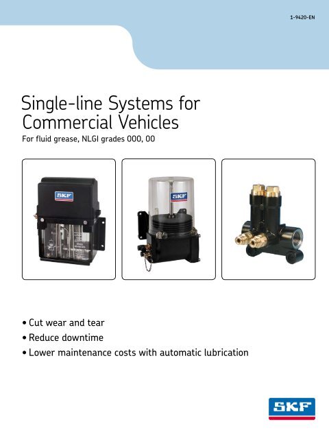
<strong>Single</strong>-<strong>line</strong> <strong>Systems</strong> <strong>for</strong><br />
<strong>Commercial</strong> <strong>Vehicles</strong><br />
For fluid grease, NLGI grades 000, 00<br />
• Cut wear and tear<br />
Reduce downtime<br />
Lower maintenance costs with automatic lubrication<br />
1-9420-EN
<strong>Single</strong>-<strong>line</strong> <strong>Systems</strong> <strong>for</strong> <strong>Commercial</strong> <strong>Vehicles</strong> <strong>for</strong> grease, NLGI grades 000, 00<br />
Table of contents<br />
2 1-9420-EN<br />
Page<br />
Alphabetical index of subject . . . . . . . . . . . . . . . . . . . . . . . . . . . . . . . . 3<br />
Order No. index . . . . . . . . . . . . . . . . . . . . . . . . . . . . . . . . . . . . 4 / 5<br />
System overview . . . . . . . . . . . . . . . . . . . . . . . . . . . . . . . . . . . . 6 / 7<br />
Lubricants and centralized lubrication systems . . . . . . . . . . . . . . . . . . . . . . . 8<br />
Planning of the system . . . . . . . . . . . . . . . . . . . . . . . . . . . . . . . 9 – 11<br />
Gear pump units<br />
KFU2-40, KFU6-20, KFUS2-64, electrically operated . . . . . . . . . . . . . . . . 12 / 13<br />
Interconnected system . . . . . . . . . . . . . . . . . . . . . . . . . . . . . . . . . . 14<br />
Piston pump PEF-90, pneumatically actuated . . . . . . . . . . . . . . . . . . . . . . 15<br />
Electronic control unit IG502-2-E . . . . . . . . . . . . . . . . . . . . . . . . . . 16 / 17<br />
Piston pumps PEF-90-S14, PEF-90-S19, pneumatically actuated,<br />
<strong>for</strong> trailer and semitrailer lubrication . . . . . . . . . . . . . . . . . . . . . . . . . 18 / 19<br />
Compact unit KFB(S) . . . . . . . . . . . . . . . . . . . . . . . . . . . . . . . . . 20 / 21<br />
Piston distributor, group VKSO . . . . . . . . . . . . . . . . . . . . . . . . . . . . 22 / 23<br />
Fittings and auxiliary equipment . . . . . . . . . . . . . . . . . . . . . . . . . . 24 – 41<br />
Topping-up pumps <strong>for</strong> fluid grease . . . . . . . . . . . . . . . . . . . . . . . . . . . . 41<br />
Connection of compressed air supply <strong>line</strong><br />
to vehicle network <strong>for</strong> a pneumatically actuated system . . . . . . . . . . . . . . . . . . 42
<strong>Single</strong>-<strong>line</strong> <strong>Systems</strong> <strong>for</strong> <strong>Commercial</strong> <strong>Vehicles</strong> <strong>for</strong> grease, NLGI grades 000, 00<br />
Alphabetical index of subject<br />
1-9420-EN<br />
Page<br />
Adapters . . . . . . . . . . . . . . . . . . . . . . . . . . . . 24 / 25<br />
Banjo fittings . . . . . . . . . . . . . . . . . . . . . . . . . . . . 27<br />
Body washers . . . . . . . . . . . . . . . . . . . . . . . . . . . . 32<br />
Bolts and screws . . . . . . . . . . . . . . . . . . . . . . . . . . 32<br />
Bracket <strong>for</strong> systems with KFU gear pump units . . . . . . . . . . . 31<br />
Cable harness <strong>for</strong> systems with<br />
– KFB(S) compact unit . . . . . . . . . . . . . . . . . . . . . . 21<br />
– KFUS2-64 gear pump units . . . . . . . . . . . . . . . . . . . 37<br />
– KFU2-40, KFU6-20 gear pump units . . . . . . . . . . . . . . 38<br />
– KFU2-40, KFU6-20 gear pump units<br />
<strong>for</strong> use on vehicles carrying hazardous goods . . . . . . . . . . 9<br />
– PEF-90 piston pump . . . . . . . . . . . . . . . . . . . . . . 40<br />
Cable strap . . . . . . . . . . . . . . . . . . . . . . . . . . . . . 33<br />
Clips . . . . . . . . . . . . . . . . . . . . . . . . . . . . . . . . . 33<br />
Compact unit KFB(S), electrically operated . . . . . . . . . . . 20 / 21<br />
Connectors . . . . . . . . . . . . . . . . . . . . . . . . . . 28 / 29<br />
Connectors <strong>for</strong> VKSO distributors . . . . . . . . . . . . . . . . . . 33<br />
Control unit IG502-2-E . . . . . . . . . . . . . . . . . . . . 16 / 17<br />
Control unit IG476 . . . . . . . . . . . . . . . . . . . . . . . . . . 19<br />
Coupler . . . . . . . . . . . . . . . . . . . . . . . . . . . . . . . 41<br />
Coupling socket . . . . . . . . . . . . . . . . . . . . . . . . . . . 41<br />
Cross joint . . . . . . . . . . . . . . . . . . . . . . . . . . . . . . 29<br />
Distributors <strong>for</strong> grease systems . . . . . . . . . . . . . . . . 22 / 23<br />
Elbows . . . . . . . . . . . . . . . . . . . . . . . . . . . . . . . 26<br />
Filler socket . . . . . . . . . . . . . . . . . . . . . . . . . . . . . 41<br />
Fittings and auxiliary equipmen . . . . . . . . . . . . . . . . 24 – 40<br />
Fixing bolts . . . . . . . . . . . . . . . . . . . . . . . . . . . . . 32<br />
Fixing brackets <strong>for</strong> mounting of distributor . . . . . . . . . . . . . 30<br />
Gear pump units KFU2-40, KFU6-20, KFUS2-64 . . . . . . . 12 / 13<br />
Hoses . . . . . . . . . . . . . . . . . . . . . . . . . . . . . . . . 35<br />
Hoses sleeves . . . . . . . . . . . . . . . . . . . . . . . . . . . . 35<br />
Indicator lights . . . . . . . . . . . . . . . . . . . . . . . . . . . . 37<br />
Interconnected system . . . . . . . . . . . . . . . . . . . . . . . . 14<br />
Lock washers . . . . . . . . . . . . . . . . . . . . . . . . . . . . 32<br />
Lubricants and centralized lubrication systems . . . . . . . . . . . . 8<br />
Page<br />
Mounting base . . . . . . . . . . . . . . . . . . . . . . . . . . . 32<br />
Mounting clips . . . . . . . . . . . . . . . . . . . . . . . . . . . . 33<br />
Nuts . . . . . . . . . . . . . . . . . . . . . . . . . . . . . . . . . 32<br />
Overflow valve . . . . . . . . . . . . . . . . . . . . . . . . . . . . 36<br />
Pin plug . . . . . . . . . . . . . . . . . . . . . . . . . . . . . . . 26<br />
Piston distributor, group VKSO . . . . . . . . . . . . . . . . . 22 / 23<br />
Piston pump<br />
– PEF-90, pneumatically actuated . . . . . . . . . . . . . . . . 15<br />
– PEF-90-S14, PEF-90-S19, pneumatically actuated . . . 18 / 19<br />
Plastic tubing . . . . . . . . . . . . . . . . . . . . . . . . . . . . 34<br />
Plug-in connectors . . . . . . . . . . . . . . . . . . . . . . . . . 27<br />
Pressure curve . . . . . . . . . . . . . . . . . . . . . . . . . . . 11<br />
Pressure switches . . . . . . . . . . . . . . . . . . . . . . . . . . 37<br />
Protective helix . . . . . . . . . . . . . . . . . . . . . . . . . . . 35<br />
Protective hose . . . . . . . . . . . . . . . . . . . . . . . . . . . 35<br />
Pulse counter, mechanical . . . . . . . . . . . . . . . . . . . . . . 19<br />
Pulse valve . . . . . . . . . . . . . . . . . . . . . . . . . . . . . 36<br />
Pump fastening plate . . . . . . . . . . . . . . . . . . . . . . . . 31<br />
Rein<strong>for</strong>cing sockets . . . . . . . . . . . . . . . . . . . . . . . . . 24<br />
Screw plugs . . . . . . . . . . . . . . . . . . . . . . . . . . . . . 26<br />
Screw unions <strong>for</strong> steel and plastic tubing . . . . . . . . . . . . . . 24<br />
Selftapping screws . . . . . . . . . . . . . . . . . . . . . . . . . . 31<br />
Socket unions . . . . . . . . . . . . . . . . . . . . . . . . . . . . 24<br />
Solenoid valve . . . . . . . . . . . . . . . . . . . . . . . . . . . . 36<br />
Spacer ring . . . . . . . . . . . . . . . . . . . . . . . . . . . . . 33<br />
Steel tubing . . . . . . . . . . . . . . . . . . . . . . . . . . . . . 34<br />
System overview . . . . . . . . . . . . . . . . . . . . . . . . 6 / 7<br />
Tapered sleeves . . . . . . . . . . . . . . . . . . . . . . . . . . . 24<br />
Tee connectors . . . . . . . . . . . . . . . . . . . . . . . . . . . 29<br />
Topping-up pumps . . . . . . . . . . . . . . . . . . . . . . . . . 41<br />
Trailer and semitrailer lubrication with<br />
PEF-90-S14 or PEF-90-S19 piston pump . . . . . . . . . 18 / 19<br />
Tube cutter . . . . . . . . . . . . . . . . . . . . . . . . . . . . . 36<br />
Tubing . . . . . . . . . . . . . . . . . . . . . . . . . . . . . . . . 34<br />
Washers . . . . . . . . . . . . . . . . . . . . . . . . . . . . . . . 24<br />
3
<strong>Single</strong>-<strong>line</strong> <strong>Systems</strong> <strong>for</strong> <strong>Commercial</strong> <strong>Vehicles</strong> <strong>for</strong> grease, NLGI grades 000, 00<br />
Order No. Index<br />
Order No. Page Order No. Page<br />
Order No. Page Order No. Page<br />
169-000-082 41<br />
169-000-084 41<br />
169-000-090 36<br />
169-000-301 36<br />
169-000-336 36<br />
179-100-025 37<br />
179-100-028 37<br />
179-100-070 37<br />
179-990-186 32<br />
181-122.01 14<br />
181-123.01 14<br />
181-140.01 14<br />
232-100-000 42<br />
232-100-001 36<br />
301-020 24<br />
401-004-512 25<br />
401-004-903 25<br />
401-004-904 25<br />
401-019-691 25<br />
404-003K 25<br />
404-004 25<br />
404-005 25<br />
404-006 24<br />
404-006K 25<br />
404-007 24<br />
404-008 28<br />
404-009 28<br />
404-010 28<br />
404-011 26<br />
404-040K 25<br />
404-040K-US 25<br />
404-040K-V1-VS 27<br />
404-045 25<br />
404-044 24<br />
404-047K 25<br />
404-050 25<br />
404-054K 25<br />
404-063 24<br />
404-072 25<br />
404-164 24<br />
404-603 24<br />
404-611 24<br />
404-612-MS 24<br />
404-662K 25<br />
404-663K 25<br />
404-673K 25<br />
404-673K-V1-VS 27<br />
405-549-049 27<br />
405-551-049 27<br />
406-004 24<br />
406-004K 25<br />
406-004K-S1 25<br />
406-004K-S2 25<br />
406-008 28<br />
406-035K 25<br />
406-045K 26<br />
406-054 24<br />
406-089K 26<br />
406-090K 26<br />
406-145K 26<br />
406-166 24<br />
406-613 24<br />
406-611 24<br />
406-612-MS 24<br />
408-004 24<br />
408-005 24<br />
408-008 28<br />
408-011 26<br />
408-406 42<br />
408-407 42<br />
408-603 24<br />
408-611 24<br />
408-612-MS 24<br />
410-008 28<br />
410-011 26<br />
410-603 24<br />
410-611 24<br />
410-612-MS 24<br />
441-006-432 42<br />
450-204-002 26<br />
453-004-471-VS 27<br />
451-004-462-VS 27<br />
451-004-498-VS 27<br />
451-004-518-VS 27<br />
454-504-041-VS 28<br />
455-529-048-VS 27<br />
455-531-048-VS 27<br />
455-546-048-VS 27<br />
456-004K-S2 25<br />
491-900-001 42<br />
504-004 28<br />
504-019 24<br />
504-040 28<br />
504-045 29<br />
504-050 26<br />
504-103 28<br />
504-114 27<br />
504-200K 26<br />
504-200K-V1-VS 27<br />
504-201K 26<br />
504-201-VS 27<br />
504-202K 26<br />
504-202-VS 27<br />
504-211K 26<br />
504-401 27<br />
506-114 27<br />
506-140 27<br />
506-145 27<br />
506-214 27<br />
506-346 27<br />
508-108 24<br />
508-145 27<br />
508-346 27<br />
510-024 27<br />
510-145 27<br />
510-343 27<br />
510-344 27<br />
510-346 27<br />
514-018K-S1 26<br />
514-018-VS 27<br />
514-018K-V1-VS 27<br />
604-001-A 33<br />
604-002-A 33<br />
604-111 33<br />
606-010-A 33<br />
608-001-A 33<br />
610-001-A 33<br />
650-050 32<br />
650-060 32<br />
650-080 32<br />
650-140 32<br />
650-160 32<br />
650-200 32<br />
734-220-K 35<br />
734-260-K 35<br />
734-300-K 35<br />
734-340-K 35<br />
774-580 35<br />
774-960 35<br />
821-400-006 32<br />
821-400-010 32<br />
847-400-004 42<br />
853-460-000 25<br />
881-260-020 30<br />
881-280-006 30<br />
881-280-007 30<br />
881-280-008 30<br />
881-280-009 30<br />
881-290-110 30<br />
881-290-111 30<br />
881-290-450 31<br />
898-110-077 27<br />
898-210-047 35<br />
898-210-061 33<br />
898-210-063 35<br />
898-210-075 35<br />
898-510-000 33<br />
898-510-002 33<br />
898-610-000 33<br />
898-710-000 33<br />
898-710-001 33<br />
941-206-104 33<br />
941-206-108 33<br />
941-208-104 33<br />
941-209-104 33<br />
941-212-104 33<br />
941-213-104 33<br />
941-215-104 33<br />
941-217-104 33<br />
941-220-104 33<br />
941-222-100 33<br />
941-227-104 33<br />
971-020-250 42<br />
982-760-061 35<br />
982-760-070 35<br />
982-760-120 35<br />
982-760-121 35<br />
982-760-130 35<br />
982-760-160 35<br />
995-000-705 41<br />
995-001-500 41<br />
995-002-140 31<br />
995-800-166 36<br />
995-800-550 36<br />
997-000-189 40<br />
997-000-373 38<br />
4 1-9420-EN
<strong>Single</strong>-<strong>line</strong> <strong>Systems</strong> <strong>for</strong> <strong>Commercial</strong> <strong>Vehicles</strong> <strong>for</strong> grease, NLGI grades 000, 00<br />
Order No. Index<br />
Order No. Page Order No. Page<br />
Order No. Page Order No. Page<br />
997-000-374 39<br />
997-000-706 21<br />
997-000-750 37<br />
997-000-904 21<br />
DAK510-S1 29<br />
DAR506 28<br />
DAR508 28<br />
DAR510 28<br />
DAR510-S1 28<br />
DAR524 29<br />
DAR534 29<br />
DAT506 29<br />
DAT508 29<br />
DAT510 29<br />
DAT510-S1 29<br />
DIN73000A2-6ST30AL 34<br />
DIN7603-A8x11.5-Cu 24<br />
DIN7603-A14x18-Cu 24<br />
DIN7603-A16x20-Cu 24<br />
DIN7981-B4.2x9.5 32<br />
DIN7981-BZ4.8x9.5 32<br />
DIN7981-BZ4.8x13 32<br />
DIN933-M6x20-8.8 32<br />
DIN933-M6x25-8.8 32<br />
DIN933-M6x30-8.8 32<br />
DIN933-M6x35-8.8 32<br />
DIN933-M6x40-8.8 32<br />
DIN933-M6x45-8.8 32<br />
DIN933-M6x55-8.8 32<br />
DIN933-M8x25-8.8 32<br />
DIN933-M8x35-8.8 32<br />
DIN934-M6-8 32<br />
DIN934-M8-8 32<br />
DIN936-M14x1.5-5 32<br />
DIN936-M16x1.5-5 32<br />
DIN936-M20x1.5-5<br />
DS-E20-S1 37<br />
DS-E25-S1 37<br />
IG476-2 19<br />
IG502-2-E 16<br />
KFB1 20<br />
KFBS1 20<br />
KFU2-40 12<br />
KFU2.U8 41<br />
KFU6-20 12<br />
KFUS2-64 12<br />
1-9420-EN<br />
P-66.60GRUEN 37<br />
P-66.60ROT 37<br />
P-66.60GELB 37<br />
P-66.62 37<br />
PEF-90 15<br />
PEF-90-S14 18<br />
PEF-90-S19 18<br />
SLH10-580 35<br />
SLH10-650 35<br />
SLH10-1600 35<br />
VKR2.U2 33<br />
VKSO2 ... 22<br />
VKSO4 ... 22<br />
VKSO6 ... 22<br />
VKU010-K 23<br />
VKU020-K 23<br />
VKU040-K 23<br />
WV-RO4x0.7VERZI 34<br />
WV-RO6x0.7VERZI 34<br />
WV-RO8x0.7VERZI 34<br />
WV-RO10x0.7VERZI 34<br />
WVN715-RO10x1.5+A89 34<br />
WVN716-RO4x0.85 34<br />
WVN716-RO6x1.25 34<br />
WVN716-RO10x2 34<br />
5
<strong>Single</strong>-<strong>line</strong> <strong>Systems</strong> <strong>for</strong> <strong>Commercial</strong> <strong>Vehicles</strong> <strong>for</strong> grease, NLGI grades 000, 00<br />
System overview<br />
Lubricant: Fluid grease, NLGI 1) grades 000, 00<br />
Selection<br />
criteria<br />
Type<br />
designation<br />
Technical<br />
data<br />
Auxiliary<br />
equipment<br />
Max. connected load (cm³)<br />
or<br />
max. number of lube points<br />
Pump suitable <strong>for</strong><br />
Type of drive<br />
80 cm³<br />
1) For progressive systems <strong>for</strong> commercial vehicles up to NLGI grade 2, see leaflet 1-9430-EN<br />
2) GGVS = Hazardous Goods Road Ordinance Germany<br />
Truck tractor<br />
Truck tractor with extra equipment<br />
Interconnected system/ semitrailer<br />
KFU units also <strong>for</strong> GGVS vehicles 2 )<br />
(with cable harness 997-000-374)<br />
electric<br />
Pump Gear pump unit<br />
KFU2-40<br />
KFUS2-64<br />
Operating pressure 38 bars<br />
Reservoir capacity<br />
Lubricant distribution<br />
Control system<br />
Main <strong>line</strong><br />
(connection: pump – distributor)<br />
Secondary <strong>line</strong><br />
(connection: distributor – lube point)<br />
page 12<br />
2.7 liters 6 liters<br />
VKSO piston distributors<br />
Electronic control unit IG502-2-E<br />
with or without monitoring function<br />
KFUS with integrated control unit IG490<br />
KFU6-20<br />
Mainly plastic tubing 10x1.5 diam., but also steel tubing 10x0.7 diam.<br />
hose SLH10-...<br />
Mainly plastic tubing 4x0.85 diam.;<br />
in case of large movement between lubrication point and chassis: hose 734 …<br />
6 1-9420-EN
36 cm³ 36 cm³<br />
approx. 20 lubrication points<br />
Truck tractor<br />
Truck tractor with small extra<br />
equipment<br />
also <strong>for</strong> GGVS vehicles 1 )<br />
pneumatic pneumatic electric<br />
Piston pump<br />
PEF-90<br />
22 to 50 bars 22 to 50 bars 38 bars<br />
3 liters 3 liters<br />
VKSO piston distributors VKSO piston distributors<br />
Electronic control unit IG502-2-E<br />
with or without monitoring function<br />
1-9420-EN<br />
Trailer / semitrailer<br />
also <strong>for</strong> GGVS vehicles 1 )<br />
Piston pump<br />
PEF-90-S14<br />
PEF-90-S19 <strong>for</strong> GGVS vehicles 1)<br />
Compact unit<br />
KFB(S)1<br />
page 15 page 18 page 20<br />
with built-in electronic control unit<br />
IG476-2 <strong>for</strong> PEF-90-S14<br />
IG476-3 <strong>for</strong> PEF-90-S19<br />
Truck tractor with small number<br />
of lubrication points<br />
Truck tractor with extra equipment<br />
also <strong>for</strong> GGVS vehicles 1 )<br />
1.4 liters<br />
Electronic control unit IG502-2-E<br />
with or without monitoring<br />
function<br />
plastic tubing 10x1.5 diam.<br />
plastic tubing 4x0.85 diam.<br />
7
<strong>Single</strong>-<strong>line</strong> <strong>Systems</strong> <strong>for</strong> <strong>Commercial</strong> <strong>Vehicles</strong> <strong>for</strong> grease, NLGI grades 000, 00<br />
Lubricants and Centralized Lubrication <strong>Systems</strong><br />
Centralized lubrication systems may only be used <strong>for</strong> their intended<br />
purpose. Centralized lubrication systems can normally be operated<br />
with the lubricants listed in the system’s documentation as long as<br />
the latter comply with the respective consistency classes and viscosity<br />
limits within the indicated temperature range. It is possible <strong>for</strong> the<br />
demands on a lubrication system’s configuration to vary concerning<br />
the lubricant and the use to which the installation is put.<br />
Given the already high “apparent viscosity”, we advise against the<br />
use of grease con<strong>for</strong>ming to NLGI Grade 0 since it is possible <strong>for</strong> fundamental<br />
properties related to delivery of the lubricant to deteriorate<br />
considerably, particularly at low ambient temperatures.<br />
If, nevertheless, a lubricant con<strong>for</strong>ming to NLGI Grade 0 is required,<br />
we recommend that its properties be checked to confirm they are<br />
adequate.<br />
Suitable Lubricants<br />
The lubricants must be suitable <strong>for</strong> the lubrication of bearings under<br />
the ambient conditions to be expected in operation. Our experience<br />
shows that suiteable lubricants are available from every well-known<br />
manufacturer. Please contact the supplier when you choose a<br />
lubricant. SKF Lubrication <strong>Systems</strong> offers to test the deliverability<br />
of a selected lubricant in the event of doubt. Lubricants that meet<br />
the identical specifications of SKF Lubrication <strong>Systems</strong> Germany AG,<br />
Daimler AG and MAN AG match each other in terms of the parameters<br />
applying to their deliverability.<br />
Lubricant manufacturers who are known to sell appropriate lubricants:<br />
ARAL AG<br />
Autol-Werke GmbH<br />
AVIA Mineralöl<br />
Axel Christiernsson<br />
BP Oil Deutschland GmbH<br />
Calypsol<br />
Castrol Ltd., England<br />
DEA<br />
1) Coupler <strong>for</strong> 1 kg drum, order No. KFU2.U8<br />
2) Topping-up pumps <strong>for</strong> 25 kg drum, order No. 169-000-082 and<br />
169-000-084<br />
Deutsche Shell GmbH<br />
ELF<br />
Esso<br />
FINA<br />
Georg Oest Mineralölwerke<br />
Mobil Schmierstoff GmbH<br />
Optimol<br />
ÖMV GmbH<br />
A corresponding lubricant can also be purchased from SKF Lubrication<br />
<strong>Systems</strong> Germany AG in 1 kg and 25 kg drums.<br />
1) 3)<br />
1 kg drum, Order No. FL1-000<br />
25 kg drum, Order No. FL25-000 2)<br />
Biodegradable types of grease available from SKF Lubrication <strong>Systems</strong><br />
Germany AG can also be used in centralized lubrication systems.<br />
1 kg drum, Order No. FL1-000BIO 1)<br />
25 kg drum, Order No. FL25-000BIO 2)<br />
To assure reliable operation of the centralized lubrication system,<br />
always pay attention to clean<strong>line</strong>ss when topping up lubricant. Dirt<br />
will lead to malfunctions in a centralized lubrication system and to<br />
destruction of the friction points.<br />
Reiner Chemische Fabrik GmbH<br />
RHENUS<br />
Wilhelm Reiners GmbH & Co.<br />
Siebert GmbH<br />
Texaco<br />
Veedol Int. Ltd., England<br />
Winterahall AG<br />
Zeller+Gmelin GmbH & Co.<br />
3) Filler bend <strong>for</strong> pumps with screw cap, order No. 169-000-037<br />
See important product usage in<strong>for</strong>mation<br />
on the back cover.<br />
8 1-9420-EN
<strong>Single</strong>-<strong>line</strong> <strong>Systems</strong> <strong>for</strong> <strong>Commercial</strong> <strong>Vehicles</strong> <strong>for</strong> grease, NLGI grades 000, 00<br />
<strong>Systems</strong> <strong>for</strong> grease, NLGI grades 000, 00<br />
• Electrically operated gear pump units KFU / KFUS<br />
• Pneumatically actuated piston pump PEF-90<br />
• Electrically operated piston pump KFB(S)1<br />
1. Planning and installation<br />
a) Determination of number of lubrication points.<br />
All friction points of the chassis and any body units, with the exception of the universal joints of the cardan shaft<br />
b) Determination of metered quantities.<br />
The tabular values correspond to the average lubricant needs of the bearings in a vehicle weighing more than 8 tons.<br />
The lubrication frequency depends on the type of operation.<br />
Truck tractors Metered qty.<br />
(cm³)<br />
1. Steering knuckle 0.4<br />
2. Spring pin 0.4<br />
3. Spring suspension 0.4<br />
4. Brake shaft 0.2<br />
5. Brake shaft, wheel side 0.1<br />
6. Linkage setting device 0.2<br />
7. Stabilizer 0.2<br />
8. Driver’s cab support 0.1<br />
9. Longitudinal control arm 0.2<br />
10. Transverse control arm 0.2<br />
11. Coupling 0.1<br />
12. Gas control 0.1<br />
13. Center bearing 0.4<br />
14. Fifth wheel support plate 0.4<br />
1-9420-EN<br />
Trailers and semitrailers Metered qty.<br />
(cm³)<br />
1. Tow bar 0.4<br />
2. Turntable 0.4<br />
3. Spring pin 0.4<br />
4. Brake shaft 0.2<br />
5. Brake shaft, wheel side 0.1<br />
6. Linkage setting device 0.2<br />
7. Hand brake 0.1<br />
8. Spare wheel 0.1<br />
9. Brake shoe pin 0.1<br />
10. Steering assembly 0.4<br />
11. Support arms 0.1<br />
12. Wearing plate 0.4<br />
c) Calculation of system capacity<br />
Maximum values:<br />
Electrically operated gear pump units<br />
KFU / KFUS . . . . . . . . . . . . . . . . . . . . . . . . . . . . =<br />
Pneumatically actuated piston pump<br />
80 cm³<br />
PEF-90 . . . . . . . . . . . . . . . . . . . . . . . . . . . . . . . =<br />
Electrically operated compact unit<br />
36 cm³<br />
KFBS . . . . . . Cf. diagram on page 21 <strong>for</strong> max. system capacity<br />
Example of how to calculate the system capacity: *)<br />
20 lubrication points, 0.4 cm³ each . . . . . . . . . . = 8 cm³<br />
10 lubrication points, 0.2 cm³ each . . . . . . . . . . = 2 cm³<br />
10 lubrication points, 0.1 cm³ each . . . . . . . . . . = 1 cm³<br />
11 cm³<br />
+25% (safety margin) . . . . . . . . . . . . . . . . . . . . . = 2.75 cm³<br />
Compressibility and expansion losses:<br />
1 cm³/m main-<strong>line</strong> tube<br />
(average value <strong>for</strong> steel and plastic tubing),<br />
assumed:<br />
12 m main-<strong>line</strong> tubing, 10 x 1 . . . . . . . . . . . . = 12 cm³<br />
. . . . . . . . . . . . . . . . . . . . . . . . . . . . . . .Total **) 25.75 cm³<br />
Buses Metered qty.<br />
(cm³)<br />
1. Stop lever 0.1<br />
2. Dual lever 0.1<br />
3. Reversing lever 0.1<br />
4. Idler arm 0.1<br />
5. Linkage setting device 0.2<br />
6. Brake shaft 0.2<br />
7. Brake shaft, wheel side 0.1<br />
8. Steering knuckle 0.4<br />
9. Turntable 0.4<br />
10. Drag link 0.4<br />
11. Knuckle pin bearing 0.4<br />
12. Axle support 0.4<br />
13. Gas control 0.1<br />
d) Selection of distributors<br />
Metered quantities of VKSO distributors: 0.1, 0.2 and 0.4 cm³.<br />
Depending on tubing layout: 2-, 4- and 6-port VKSO distributors.<br />
Two different distributors are connected to one manifold with a<br />
VKR 2.U2 connector<br />
e) Tubing connections<br />
Main <strong>line</strong> connections to VKSO distributors:<br />
M16x1.5 thread <strong>for</strong> 10 mm diam. tube,<br />
tapped <strong>for</strong> solderless tube connection.<br />
Secondary (lubrication) <strong>line</strong> connections<br />
to VKSO distributors: with plugin connectors.<br />
*) The example applies only to KFU and PEF90 units. The safety margins <strong>for</strong> the<br />
KFB(S) units are already worked into the table.<br />
**) If the calculated system capacity exceeds the capacity of the pump unit, a second<br />
pump unit must be used. A second unit is also required when the vehicle is operated<br />
<strong>for</strong> extended periods of time at temperatures below –20 °C with a main-<strong>line</strong> train of<br />
more than 17 m.<br />
9
<strong>Single</strong>-<strong>line</strong> <strong>Systems</strong> <strong>for</strong> <strong>Commercial</strong> <strong>Vehicles</strong> <strong>for</strong> grease, NLGI grades 000, 00<br />
f) Installation<br />
(Detailed installation instructions are<br />
available on request.)<br />
This in<strong>for</strong>mation is supposed to be a<br />
guide <strong>line</strong> and aid <strong>for</strong> the fitter. It will<br />
enable him to install the equipment<br />
on vehicles even if there are no tubing<br />
layouts available, or only incomplete ones.<br />
For the prevalent, standard types of<br />
commercial vehicles, we have prepared<br />
tubing layouts that show how the installations<br />
are supposed to be done.<br />
If required, these layouts will be mailed<br />
free of charge.<br />
Additional superstructures and special<br />
vehicles can be outfitted on the basis of<br />
these layouts.<br />
The preassembled VKSO distributors <strong>for</strong><br />
standard systems are supplied with a<br />
preset metered quantity, but they can be<br />
changed to another quantity of lubricant<br />
if necessary.<br />
Install the VKSO distributors at suitable<br />
locations on the vehicle and connect to<br />
the tubing.<br />
Max. length of the secondary <strong>line</strong>s is 6 m<br />
(connection: distributor – lubrication point).<br />
Tighten the socket unions, but do not<br />
overtighten (maximum of 1 1 /2 turns).<br />
The tapered sleeves and tubing are<br />
slightly de<strong>for</strong>med when tightened, thus<br />
offering no resistance as a fixing bolt<br />
would when tightened.<br />
Attention must be paid to the following<br />
when installing the secondary <strong>line</strong>s:<br />
– Steering lock angle, sagging, chafing<br />
spots.<br />
– Keep away from heat sources.<br />
Install the pump and control unit at a<br />
suitable place.<br />
Connect hoses and make electrical<br />
connections.<br />
Some installation hints:<br />
– Use the existing holes drilled in the<br />
chassis and in other vehicle parts <strong>for</strong><br />
the installation.<br />
– Span large boreholes with body washers.<br />
– Lay 4 x 0.85 plastic tubing (as per<br />
WVN716, flexible) between distributors<br />
and lubrication points.<br />
– Use 734...-K hose <strong>line</strong>s to connect<br />
nonstationary lubrication points and<br />
lubrication points that are subject to<br />
heavy mechanical stress and strain.<br />
– The compressed air <strong>for</strong> the PEF-90<br />
pneumatically actuated pump must<br />
be taken from a <strong>line</strong> <strong>for</strong> auxiliary loads.<br />
The regulations of the german TÜV<br />
(Technical Control Board) must be<br />
observed.<br />
– The pertinent Hazardous Goods Road<br />
Ordinance Germany (GGVS) must be<br />
observed in the case of tank trucks<br />
and other vehicles carrying hazardous<br />
goods.<br />
The following pump unit can be used:<br />
electrically operated gear pump units<br />
KFU2-40, KFU6-20 in conjunction with<br />
cable harness 997-000-374; compact<br />
units KFB(S) in conjunction with cable<br />
harness 997-000-630 or 997-000-650.<br />
Furthermore, the pressure switch <strong>line</strong><br />
must likewise be laid in corrugated tubing<br />
2. Operation and maintenance<br />
In the case of automatically controlled<br />
systems, with the exception of KFB(S)<br />
compact units, the indicator light goes<br />
on <strong>for</strong> about 3 seconds every time the<br />
ignition is switched on. (See 3.a <strong>for</strong> malfunctions<br />
of indicator light.)<br />
For the most part, maintenance is limited<br />
to topping up with clean lubricantwhen<br />
necessary.<br />
All tube connections should be checked <strong>for</strong><br />
a tight fit when the vehicle is inspected.<br />
Replace torn or worn hose <strong>line</strong>s after<br />
eliminating the cause of the problem,<br />
and trigger test lubrication. Actuate automatic<br />
systems by hand and observe the<br />
indicator light.<br />
The main <strong>line</strong> (connection: pump –<br />
distributor) is monitored by a pressure<br />
switch that reports the build-up of<br />
pressure. Exception: KFBS and KFUS<br />
units. If the indicator light does not light<br />
up, or if it burns constantly in the case<br />
of automatic systems, this means the<br />
pressure has failed to build up.<br />
Select a smaller metered quantity <strong>for</strong><br />
highly overlubricated points and a higher<br />
quantity <strong>for</strong> dry points.<br />
If the entire system is overlubricated or<br />
underlubricated, there can be malfunction:<br />
in this case, follow the instructions in 3.b<br />
or 3.c below.<br />
3. Malfunctions and their elimination<br />
a) Fault indication by indicator light.<br />
The indicator light does not go out about<br />
3 seconds after the ignition is switched<br />
on or the motor has been started.<br />
Check lubricant level in the reservoir;<br />
top up lubricant if necessary and bleed the<br />
system.<br />
In the case of electrically operated gear<br />
pumps, loosen the screw union of the<br />
main <strong>line</strong> while the pump is running.<br />
There must be a continuous discharge of<br />
lubricant.<br />
In the case of pneumatically operated<br />
systems:<br />
Check the compressed air supply.<br />
Minimum pressure is 6 bars.<br />
Check pump function.<br />
The piston stroke must be heard or felt<br />
when compressed air is applied.<br />
Check pressure in main <strong>line</strong>.<br />
Loosen the lubrication-point connection<br />
and check whether the distributor is<br />
delivering lubricant. If it is, the fault must<br />
be looked <strong>for</strong> in the pressure switch,<br />
electrical wiring or control unit.<br />
10 1-9420-EN
<strong>Single</strong>-<strong>line</strong> <strong>Systems</strong> <strong>for</strong> <strong>Commercial</strong> <strong>Vehicles</strong> <strong>for</strong> grease, NLGI grades 000, 00<br />
Please note:<br />
The distributor will not feed lubricant until<br />
the main <strong>line</strong> is relieved of pressure again. It<br />
is there<strong>for</strong>e called a “relubrication distributor”.<br />
Check electrical connections:<br />
Is power available?<br />
Are all terminals tight?<br />
Check the indicator light, solenoid valve,<br />
pressure switch and control unit.<br />
Main <strong>line</strong> connections, main hose <strong>line</strong>s in<br />
particular, must be checked <strong>for</strong> leakage. Then<br />
check whether the pump valves are dirty.<br />
1-9420-EN<br />
b) Entire system insufficiently lubricated.<br />
Install a pressure gauge in the main <strong>line</strong><br />
and check the pressure build-up and<br />
relief. Min. pressure build-up is 30 bars.<br />
A maximum residual pressure of 1 bar<br />
may remain after the pressure is relieved<br />
(measured at pump‘s outlet port).<br />
c) Entire system is overlubricated.<br />
Check setting of control unit and increase<br />
interval time if necessary.<br />
d) Individual lubrication points are overlubricated<br />
or underlubricated.<br />
Change metered quantity.<br />
e) Distributor faults.<br />
Replace distributors.<br />
Please note!<br />
A high level of clean<strong>line</strong>ss must be maintained<br />
when doing any work on the system,<br />
es pecially when replacing metering nipples<br />
on distributors. Dirt in the system causes<br />
malfunctions.<br />
Never use trichloroethylene, perchloroethylene<br />
or similar liquids aggressive to<br />
Perbunan when cleaning centralized lubrication<br />
systems. Suitable cleaning agents are<br />
petroleum ether or kerosene.<br />
Pressure curve in main <strong>line</strong> in the case of systems with VKSO relubrication distributors<br />
Pneumatically actuated piston pumps and<br />
electrically operated gear pump units have<br />
an identical pressure curve, but the time<br />
required <strong>for</strong> the pressure build-up will generally<br />
be shorter with pneumatically actuated<br />
piston pumps.<br />
The maximum pressure reached in the main<br />
<strong>line</strong> depends on the actuating pressure of the<br />
piston pumps or on the pressure intensity<br />
of the safety valve in the case of gear pump<br />
units.<br />
Pneumatically actuated<br />
piston pump . . . . . . . . . . . . . . 22-50 bars<br />
Electrically operated<br />
KFU gear pump units . . . . . . . . . ≈ 38 bars<br />
Electrically operated<br />
KFBS compact units . . . . . . . . . . ≈ 30 bars<br />
(length of main <strong>line</strong> limited to 10 m)<br />
������������������<br />
������������<br />
0<br />
��������<br />
����������������<br />
����<br />
���������<br />
��������������<br />
�����������������<br />
Functional sequence<br />
At the end of the preset interval time, the<br />
pump motor is switched on and the pressure<br />
required by the system built up. This is reported<br />
to the control unit by the actuation of<br />
the pressure switch. At the end of the pump<br />
running time, the pump motor is switched off<br />
and a new interval time begins.<br />
��������<br />
�����������<br />
If there is no signal from the pressure switch<br />
while the pump is in operation, the control<br />
unit will report a fault at the end of the pump<br />
running time. This is signaled by the constant<br />
burning of the indicator light.<br />
The metering chambers of the distributors<br />
are filled with lubricant during the pressure<br />
build-up in the main <strong>line</strong>.<br />
����������������������������������������<br />
�������������������������<br />
����������������������������<br />
�������������<br />
����������������������������<br />
������������������������������<br />
The relief of pressure in the main <strong>line</strong> via the<br />
pressure relief valve starts when the pump is<br />
switched off. The lubricant from the metering<br />
chambers is delivered to the lubrication<br />
points by the spring-loaded distributor<br />
pistons at the same time as the pressure is<br />
relieved.<br />
The KFB(S) compact units have the same<br />
functional sequence, but the pressure buildup<br />
is not monitored in this case.<br />
*) depending on size of system and pump<br />
11
<strong>Single</strong>-<strong>line</strong> <strong>Systems</strong> <strong>for</strong> <strong>Commercial</strong> <strong>Vehicles</strong> <strong>for</strong> grease, NLGI grades 000, 00<br />
Gear pump units KFU2-40, KFU6-20, KFUS2-64<br />
with reservoir, electrically operated<br />
The gear pump unit consists mainly of a<br />
gear pump with relief valve, safety valve, DC<br />
motor, transparent lubricant reservoir, filler<br />
socket and angle bracket. The DC motor and<br />
filler socket are covered by a hood to protect<br />
them from dirt. The hood snaps into place on<br />
both sides of the reservoir lid.<br />
Function<br />
The gear pump continuously supplies lubricant<br />
to the relubrication distributors via the<br />
main <strong>line</strong> network when the pump is in operation.<br />
As soon as the metering chambers of<br />
the distributors are full, the excess lubricant<br />
flows back into the reservoir via<br />
the safety valve.<br />
Technical data<br />
Order No. . . . . . . . . . . . . . . . . . . . . . . . KFU2-40 . . . . KFU6-20 *)<br />
Order No. . . . . . . . . . . . . . . . . . . . . . . . KFUS2-64<br />
Reservoir capacity . . . . . . . . . . . . . . . . . . 2.7 l . . . . . . . 6 l<br />
Weight (without lubricant) . . . . . . . . . . . . . ≈ 5.5 kg . . . . . ≈ 7.3 kg<br />
Operating voltage . . . . . . . . . . . . . . . . . . . 12 or 24 V DC<br />
Please quote required voltage when ordering.<br />
12 V fuse <strong>for</strong> KFU . . . . . . . . . . . . . . . . . . 7.5 A<br />
24 V fuse <strong>for</strong> KFU . . . . . . . . . . . . . . . . . . 7.5 A<br />
12 V fuse <strong>for</strong> KFUS . . . . . . . . . . . . . . . . . 16 A<br />
24 V fuse <strong>for</strong> KFUS . . . . . . . . . . . . . . . . . 8 A<br />
Flow rate . . . . . . . . . . . . . . . . . . . . . . . . . 140 cm³/min<br />
at back pressure p = 38 bars and temperature t = 25 °C<br />
System capacity <strong>for</strong> single<strong>line</strong> systems . . max. 80 cm³<br />
Units with relief valve and safety valve<br />
Max. operating pressure . . . . . . . . . . . . . 38 +2<br />
-3 bars<br />
(corresponds to actual value of built-in safety valve)<br />
Permissible operating temperature . . . . . –25 °C to +75 °C<br />
Type of enclosure . . . . . . . . . . . . . . . . . . IP 59 k<br />
Lubricant . . . . . . . . . . . . . . . . . . . . . . . . . fluid grease,<br />
NLGI grades 000, 00<br />
Associated control unit <strong>for</strong> KFU: IG502-2-E,<br />
KFUS unit with integrated control unit: IG490<br />
*) This unit should only be used <strong>for</strong> systems with a minimum lubricant<br />
consumption of 6 l/year.<br />
At the end of the pump running time (start<br />
of the interval time), the pressure relief valve<br />
opens so that the pressure in the main <strong>line</strong><br />
can drop to a residual pressure of 0.2 to 1.0<br />
bar. The spring-loaded pistons of the distributors<br />
can now deliver lubricant from the<br />
metering chambers to the lubrication points.<br />
Nearly every size of system on commercial<br />
vehicles, including superstructures, can be<br />
supplied by one single pump when a KFU2-<br />
40 or KFU6-20 pump unit is used.<br />
Furthermore, the semitrailer or trailer can be<br />
connected using an interconnected system,<br />
but this is only advisable when the motor vehicle<br />
and semitrailer/trailer are<br />
rarely or never disconnected from each other.<br />
Hydraulic layout<br />
Main <strong>line</strong><br />
to system<br />
Pressure relief valve<br />
The KFU units must be used with cable harness<br />
997-000-374 on vehicles approved <strong>for</strong><br />
the transport of hazardous goods by road<br />
(GGVS).<br />
Associated cable harness <strong>for</strong> KFU,<br />
order No. 997-000-373;<br />
cable harness <strong>for</strong> KFUS2-64,<br />
order No. 997-000-750.<br />
12 1-9420-EN<br />
�<br />
Safety valve<br />
Filler socket
<strong>Single</strong>-<strong>line</strong> <strong>Systems</strong> <strong>for</strong> <strong>Commercial</strong> <strong>Vehicles</strong> <strong>for</strong> grease, NLGI grades 000, 00<br />
KFU2-40 with 2.7 l reservoir<br />
KFU6-20 with 6 l reservoir<br />
KFUS2-64 with 2.7 l reservoir<br />
1) Coupling bush <strong>for</strong> filler socket,<br />
order No. 995-001-500 (please order separately).<br />
2) The cover must be removed <strong>for</strong> filling. Press in cover<br />
with both hands at the positions marked and lift.<br />
3) Ports tapped <strong>for</strong> solderless tube connection.<br />
1-9420-EN<br />
Connection port<br />
<strong>for</strong> main <strong>line</strong><br />
to system<br />
Overfill and<br />
venting tube<br />
Transparent<br />
reservoirt<br />
���<br />
���<br />
����<br />
Overfill and<br />
venting tube<br />
�<br />
��<br />
���<br />
���<br />
���<br />
��<br />
��<br />
���<br />
���<br />
���<br />
���<br />
���<br />
�<br />
���<br />
����<br />
Pushbutton <strong>for</strong> intermediate lubrication<br />
Filler socket 1)<br />
��<br />
�����<br />
�� ��<br />
���<br />
������� ��<br />
�<br />
�<br />
� �<br />
�����<br />
�<br />
�<br />
Quick connector<br />
<strong>for</strong> main <strong>line</strong><br />
El. connection <strong>for</strong><br />
2-pole plug connector M24x1<br />
with polarity reversal protection<br />
���<br />
���<br />
El. connection<br />
4-pole<br />
��<br />
� �<br />
� �<br />
�����<br />
�<br />
�<br />
�<br />
�<br />
��<br />
��<br />
���<br />
�����<br />
13
<strong>Single</strong>-<strong>line</strong> <strong>Systems</strong> <strong>for</strong> <strong>Commercial</strong> <strong>Vehicles</strong> <strong>for</strong> grease, NLGI grades 000, 00<br />
Interconnected system with KFU2-40, KFU6-20, KFUS2-64<br />
gear pump units, electrically operated,<br />
<strong>for</strong> truck tractors with trailer or semitrailer without frequent change of vehicles<br />
The unit is installed on the truck tractor, and<br />
the main <strong>line</strong> of the following vehicle is connected<br />
to the centralized lubrication system<br />
of the truck tractor via a plug and socket<br />
coupling.<br />
The feed capacity is dimensioned so that<br />
all standard interconnected vehicles can be<br />
supplied.<br />
The units must be used with cable harness<br />
997-000-374 on vehicles approved <strong>for</strong><br />
the transport of hazardous goods by road<br />
(GGVS).<br />
Associated control unit: IG502-2-E<br />
Coupling parts <strong>for</strong> interconnected system<br />
�<br />
�<br />
To centralized lubrication<br />
system of truck tractor<br />
Tee piece Main <strong>line</strong> ø10 *) Plug Socket Hose <strong>line</strong><br />
DAT510 995-000-818 995-000-819 WVN711-10, 3000 mm long<br />
(<strong>for</strong> 2-axle trailer, 4000 mm long)<br />
from unit<br />
KFU2-40<br />
KFU6-20<br />
Angle bracket<br />
881-250-004<br />
with borehole ø17<br />
Cap<br />
898-630-000<br />
Plug<br />
898-630-002<br />
Dummy plug *)<br />
to portect socket<br />
when disconnected*) Washer<br />
827-200-006<br />
Parts <strong>for</strong> trcuk tractor, Parts <strong>for</strong> trailer or semitrailer,<br />
order No. 181-128.01 order No 181-129.01<br />
Plug 833-170-005<br />
Cap 898-630-000<br />
Nut DIN936-M14x1.5<br />
Washer 650-140<br />
Hose shell Screw union<br />
406-710-002 410-313<br />
406-810-002 Connector<br />
DAR510<br />
Coupling parts <strong>for</strong> interconnected Parts <strong>for</strong> trailer or semitrailer<br />
system, complete Complete, but with spiral tubing 1 ) with spiral tubing 1 )<br />
Order No. Order No. Order No.<br />
181-123.01 181-122.01 181-140.01<br />
1 ) Spiral tubing, order No. 167-003-501<br />
To centralized<br />
lubrication<br />
system of trailer<br />
or semitrailer<br />
14 1-9420-EN<br />
{<br />
�<br />
*) Please order separately if required
<strong>Single</strong>-<strong>line</strong> <strong>Systems</strong> <strong>for</strong> <strong>Commercial</strong> <strong>Vehicles</strong> <strong>for</strong> grease, NLGI grades 000, 00<br />
Piston pump PEF-90, pneumatically actuated<br />
The unit consists mainly of<br />
– a lubricant pump in the <strong>for</strong>m of a<br />
pneumatically actuated piston pump with<br />
spring reset,<br />
– suction valve,<br />
– combination pressure and relief valve,<br />
– lubricant<br />
reservoir in the <strong>for</strong>m of a bellows,<br />
including protective holder,<br />
– filler socket <strong>for</strong> topping up the lubricant<br />
reservoir.<br />
Function<br />
The delivery piston is moved in the direction<br />
of the outlet after pressurization with compressed<br />
air. As a result, the lubricant that<br />
flowed into the pump chamber through the<br />
suction valve is delivered to the system via<br />
the combination pressure and relief valve.<br />
Technical data<br />
1-9420-EN<br />
After the compressed air is switched off, the<br />
delivery piston is returned to its initial position<br />
by the reset spring. Due to the resulting<br />
underpressure, the combination pressure<br />
and relief valves also return to their initial<br />
position, thereby opening the pressure relief<br />
bore; the pressure in the main <strong>line</strong> is relieved<br />
as a result.<br />
Due to the pressure relief, the paths from the<br />
metering chambers to the friction point are<br />
opened in the distributors so that the springloaded<br />
metering pistons can now deliver<br />
lubricant to the friction point.<br />
The inlet valve is opened by the underpressure<br />
resulting from the return motion of the piston,<br />
and new lubricant flows into the pump<br />
chamber.<br />
This ends the work cycle.<br />
Order No. . . . . . . . . . . . . . . . . . . . . . . . . . . . . PEF-90<br />
Delivery rate per stroke . . . . . . . . . . . . . . . . . . 48 cm³<br />
Operating pressure (depending on air pressure) 22 to 50 bars<br />
Max. perm. P1 air pressure <strong>for</strong> the pump . . . . 10 bars<br />
Permissible operating temperature . . . . . . . . . . –25 °C to +80 °C<br />
Reservoir capacity . . . . . . . . . . . . . . . . . . . . . . 3 liters<br />
Lubricant . . . . . . . . . . . . . . . . . . . . . . . . . . . . . . fluid grease, NLGI<br />
grades 000, 00<br />
Lubricant<br />
reservoir<br />
�������<br />
��<br />
���<br />
�����<br />
���<br />
���<br />
����<br />
Protective<br />
holder<br />
���<br />
��<br />
�����<br />
���� ���<br />
���<br />
Air inlet Filler socket<br />
Please note<br />
When filling <strong>for</strong> the first time, overfill the<br />
pump unit in order to keep air from becoming<br />
trapped in the bellows.<br />
Materials:<br />
Cylinder/piston . . . . . . . . . . . . . . . . . . . . . . . . . . Al Mg Si 0.5<br />
Valves . . . . . . . . . . . . . . . . . . . . . . . . . . . . . . . . steel, Cu Zn 40 Pb 2<br />
Seals, lubricant reservoir . . . . . . . . . . . . . . . . . NBR<br />
Mounting position . . . . . . . . . . . . . . . . . . . . . . . as shown<br />
Weight (without lubricant) . . . . . . . . . . . . . . . . . approx. 4.7 kg<br />
Make sure the pump is installed without distortion!<br />
Associated control unit: IG502-2-E<br />
Overfill opening<br />
Lubricant<br />
outlet<br />
Hydraulic layout<br />
�<br />
��<br />
��<br />
P1 = air <strong>line</strong> from compressed air network<br />
P2 = main <strong>line</strong> of system<br />
P1 = when connected to tubing:<br />
order adapter 406-054 <strong>for</strong> 6 mm diam.<br />
tube and washer 508-108 separately.<br />
P2 = ports tapped <strong>for</strong> solderless tube<br />
connection <strong>for</strong> tube 10 mm diam.<br />
See page 41 <strong>for</strong> grease topping-up pumps.<br />
15
<strong>Single</strong>-<strong>line</strong> <strong>Systems</strong> <strong>for</strong> <strong>Commercial</strong> <strong>Vehicles</strong> <strong>for</strong> grease, NLGI grades 000, 00<br />
Electronic control unit IG502-2-E<br />
<strong>for</strong> systems with KFU2-40, KFU6-20 gear pump units or PEF-90 piston pump<br />
Operating and display elements<br />
The IG502 control units come with an<br />
operating and display panel that can be used<br />
to check, monitor and, if necessary, readjust<br />
the parameters as well as programmed<br />
functions.<br />
Modes of operation<br />
PAUSE (pump OFF) with timer function<br />
– programmable from 0.1 to 99.9 h<br />
– digital display after invoking:<br />
tPA (t = timer, PA = PAUSE)<br />
The PAUSE (the interval between two lube<br />
cycles) is determined by a clock cycle (timer)<br />
generated by the control system and by the<br />
value (in hours) programmed <strong>for</strong> PAUSE<br />
(tPA).<br />
PAUSE (pump OFF) with counter function<br />
– programmable from 1 to 999 pulses<br />
– digital display after invoking:<br />
cPA (c = counter, PA = PAUSE)<br />
The PAUSE (the interval between two lube<br />
cycles) is determined by the interval between<br />
the time signals arrive at the counter input<br />
and by the value programmed <strong>for</strong> PAUSE<br />
(cPA).<br />
CONTACT (pump ON) with timer function<br />
– programmable from 1 to 99.9 minutes<br />
– digital display after invoking:<br />
tCO (t = timer, CO = CONTACT)<br />
The pump running time (CONTACT) is<br />
determined by a clock cycle (timer) generated<br />
by the control system and by the value (in<br />
minutes) programmed <strong>for</strong> CONTACT (tCO).<br />
Monitoring functions<br />
PS (Pressure Switch)<br />
This monitoring function is intended <strong>for</strong><br />
centralized grease lubrication systems<br />
designed <strong>for</strong> NLGI grades 000, 00, 0 in which<br />
the pressure in the main <strong>line</strong> is monitored.<br />
Once the monitoring parameter PS has been<br />
programmed, the pressure switch installed<br />
in the main <strong>line</strong> is monitored <strong>for</strong> respective<br />
signals while the pump is in operation.<br />
CS (Cycle Switch)<br />
This monitoring function is intended <strong>for</strong><br />
centralized grease lubrication systems with<br />
progressive feeders in which a piston‘s motion<br />
is monitored with a cycle switch.<br />
Once the monitoring parameter CS has been<br />
set, the cycle switch installed on the progressive<br />
feeder is monitored <strong>for</strong> the respective<br />
signal while the pump is in operation.<br />
The respective monitoring parameter<br />
selected (PS or CS) is displayed by the lighting<br />
of the corresponding LED in the PAUSE<br />
(interval) mode.<br />
Without monitoring (OFF)<br />
The monitoring can also be switched off<br />
(OFF).<br />
The control system then works without<br />
direct monitoring of the pressure build-up in<br />
the main <strong>line</strong> or without monitoring of the<br />
feeder‘s operation. The PS or CS LEDs do<br />
not light up.<br />
Fault displays<br />
The red FAULT LED shows a group fault<br />
signal when it constantly burns. The cause of<br />
the fault signal is additionally shown on the<br />
digital display to help with troubleshooting.<br />
The following messages are provided <strong>for</strong>:<br />
FPS – pressure build-up fault when monitoring<br />
is effected with a pressure switch.<br />
FCS – cycle switch fault when a progressive<br />
feeder is not working or is blocked<br />
(<strong>line</strong> break).<br />
Special functions<br />
Control units comprising the IG502 group<br />
have two electronic counters in which times<br />
are permanently stored; they cannot be<br />
changed by the user.<br />
These counters are used to check the operation<br />
of the centralized lubrication system and<br />
are read out via the LED display.<br />
Fault-hours counter<br />
The amount of time a farm or construction<br />
machine has been run with a non-functioning<br />
centralized lubrication system (e.g. with<br />
no lubricant in the reservoir) is added up by<br />
the fault-hours counter.<br />
The counter‘s contents are automatically<br />
updated and cannot be cleared. The current<br />
state of the counter can be displayed by invoking<br />
function parameter Fh on the display<br />
and operating panel. The current value is<br />
displayed in hours.<br />
The counter has a resolution of 0.1 hour, i.e.<br />
the smallest displayable interval amounts to<br />
6 minutes.<br />
Elapsed-hours counter<br />
The electronic elapsed-hours counter adds<br />
up the time in which power is applied to the<br />
control unit.<br />
The counter‘s contents are automatically updated<br />
and cannot be cleared. The current<br />
state of the counter can be displayed by invoking<br />
function parameter Oh on the display<br />
and operating panel. The current value is<br />
displayed in hours.<br />
The counter has a resolution of 0.1 hour, i.e.<br />
the smallest displayable interval amounts to<br />
6 minutes.<br />
The units meet the legal requirements of<br />
the applicable EC Directives.<br />
The unit is EC Type Approved (e1).<br />
Application<br />
The IG502-2-E universal control unit is used<br />
to control and monitor centralized lubrication<br />
systems on commercial vehicles. The control<br />
unit‘s functions can be programmed. Its<br />
housing dimensions, electrical connection<br />
and functions are compatible with those of<br />
SKF control units currently in use.<br />
The operating elements are protected by a<br />
foil against moisture and dirt. The unit has<br />
a voltage-independent data memory. This is<br />
where the configuration data and parameters<br />
are stored. As a result, the control unit is not<br />
dependent on a constant supply of voltage.<br />
If an external indicator light SL has been<br />
installed in the driver‘s cab, it will light up <strong>for</strong><br />
3 seconds after the unit is switched on.<br />
Installation<br />
The unit has to be installed in a closed compartment<br />
on the vehicle where it is protected<br />
from ambient influences. It is fastened in<br />
place with straps.<br />
The IG502-2-E is accommodated in an IP 20<br />
type of enclosure. The plug con<strong>for</strong>ms to<br />
safety class IP 00.<br />
If the control unit is installed in a hard-toreach<br />
place, it is advisable to additionally<br />
install an illuminated pushbutton on the<br />
dashboard to serve as a fault display and<br />
function check.<br />
16 1-9420-EN
<strong>Single</strong>-<strong>line</strong> <strong>Systems</strong> <strong>for</strong> <strong>Commercial</strong> <strong>Vehicles</strong> <strong>for</strong> grease, NLGI grades 000, 00<br />
Electronic control unit IG502-2-E<br />
1-9420-EN<br />
��<br />
������<br />
Wiring diagram<br />
���<br />
���<br />
�����<br />
�������<br />
�������<br />
�������<br />
�<br />
��<br />
�����<br />
������<br />
������������������������������<br />
��������������������������������<br />
��<br />
�����<br />
� �� ��<br />
�<br />
����� �� �����<br />
� �� ��<br />
Z<br />
����<br />
�<br />
��<br />
��<br />
Normal functional sequence<br />
���<br />
�<br />
��<br />
�����<br />
����<br />
���<br />
������<br />
(time axis not to scale)<br />
�� �� �� ��� �� �� �� �����<br />
��<br />
������<br />
�� ���<br />
tu = ignition interruption<br />
ts = contact time<br />
tp = interval time<br />
30 = battery + / vehicle network<br />
15 = operating voltage + / after ignition “ON”<br />
31 = operating voltage –<br />
DK/MK = pushbutton / intermediate lubrication or pulsecounter input<br />
PS/CS = pressure switch / cycle switch<br />
M = pump motor<br />
SL = indicator light<br />
Z = ignition loc<br />
F = fuse 5 A<br />
�<br />
�<br />
Technical data<br />
Order No . . . . . . . . . . . . . . . . . . . . . . . . . . . . . . IG502-2-E<br />
Associated cable harness<br />
<strong>for</strong> KFU2-40, KFU6-20, order No. . . . . . . . . . . . 997-000-373<br />
<strong>for</strong> vehicles with hazardous goods, order No. . . . 997-000-374<br />
<strong>for</strong> PEF-90, order No. . . . . . . . . . . . . . . . . . . . . . 997-000-189<br />
Control votlage 1) . . . . . . . . . . . . . . . . . . . . . . . . 12 or 24 V DC<br />
Max. contact load, terminal M . . . . . . . . . . . . . . 10 A<br />
SL-output . . . . . . . . . . . . . . . . . . . . . . . . . . . . . . 4 W<br />
Type of enclosure 2) . . . . . . . . . . . . . . . . . . . . . . IP 40, DIN 40050<br />
Temperature range . . . . . . . . . . . . . . . . . . . . . . . –25 to +75 °C<br />
Max. fusing . . . . . . . . . . . . . . . . . . . . . . . . . . . . . 5 A<br />
Programmable interval times . . . . . . . . . . . . . . . 0.1 to 99.9 h<br />
Programmable pump running time . . . . . . . . . . 0.1 to 99.9 min<br />
Programmable pulses . . . . . . . . . . . . . . . . . . . . . 1 to 999<br />
Elapsedtime, fault hours memory . . . . . . . . . . . . 0 to 99999.9 h<br />
1) Please quote control voltage when ordering.<br />
2) Warranted <strong>for</strong> vertical (plug-in connector pointing downward) and<br />
horizontal installation.<br />
LED PAUSE<br />
lights in intervals.<br />
LED CONTACT<br />
lights when pump running.<br />
LED CS<br />
lights <strong>for</strong> monitoring with cycle switch function.<br />
LED PS<br />
lights <strong>for</strong> monitoring with pressure switch function.<br />
LED FAULT<br />
lights <strong>for</strong> fault monitoring (cycle or pressure switch).<br />
Pushbutton DK<br />
17
<strong>Single</strong>-<strong>line</strong> <strong>Systems</strong> <strong>for</strong> <strong>Commercial</strong> <strong>Vehicles</strong> <strong>for</strong> grease, NLGI grades 000, 00<br />
Trailer and semitrailer lubrication<br />
with PEF-90-S14 pneumatically actuated piston pump including IG476-2 electronic control unit<br />
with PEF-90-S19 pneumatically actuated piston pump including IG476-2 electronic control unit<br />
<strong>for</strong> use on vehicles carrying hazardous goods<br />
PEF-90-S.. Rear view of PEF-90-S14 Rear view of PEF-90-S19<br />
Diagram of a system<br />
Compressed air<br />
tank<br />
Overflow valve 232-100-001<br />
(overflow pressure 6 bars)<br />
3/2-way pulsed<br />
valve 995-800-166<br />
Electr. control <strong>line</strong><br />
from stop-light switch<br />
IG476-2 electronic control unit<br />
���<br />
�� ���<br />
Weight (without lubricant): approx 11.4 kg<br />
������<br />
�����<br />
�������<br />
��<br />
���<br />
��<br />
��<br />
���<br />
��<br />
P1 = compressed air connection port<br />
P2 = pressure port to system<br />
�<br />
��<br />
���<br />
Filler socket<br />
Technical data<br />
of piston pumps<br />
see PEF-90<br />
page 15<br />
��<br />
�������<br />
18 1-9420-EN<br />
�����<br />
�����<br />
��<br />
Pulsed valve compl.<br />
order No. 995-800-166<br />
�<br />
�<br />
Electronic<br />
control unit<br />
Exhaust <strong>line</strong><br />
<strong>for</strong> PEF-90-S19<br />
with corrugated tube (used on<br />
vehicles carrying hazardous goods)
<strong>Single</strong>-<strong>line</strong> <strong>Systems</strong> <strong>for</strong> <strong>Commercial</strong> <strong>Vehicles</strong> <strong>for</strong> grease, NLGI grades 000, 00<br />
Trailer and semitrailer lubrication<br />
with PEF-90-S14 pneumatically actuated piston pump including IG476-2 electronic control unit<br />
with PEF-90-S19 pneumatically actuated piston pump including IG476-2 electronic control unit<br />
<strong>for</strong> use on vehicles carrying hazardous goods<br />
Functional sequence<br />
The switching pulses <strong>for</strong> the stop light are<br />
registered and added in the electronic control<br />
unit at an interval of at least one second.<br />
As soon as the preset number of brake<br />
applications is reached, the pulse-controlled<br />
3/2-way solenoid valve is energized <strong>for</strong> a<br />
lubricating time of at least 40 seconds,<br />
thereby pressurizing the compressed air<br />
cylinder of the piston pump. The delivery<br />
piston of the pump executes one working<br />
stroke and the lubricant distributors are filled<br />
(relubrication distributors).<br />
Application of the brakes during the lubricating<br />
time is ignored by the control unit.<br />
The first application of the brakes at the<br />
conclusion of the lubricating time reverses<br />
the valve. As a result, the compressed air<br />
cylinder of the piston pump is relieved of<br />
pressure, and the delivery piston returns<br />
to its initial position. At the same time, this<br />
relieves the pressure in the main <strong>line</strong> so that<br />
the distributors can now deliver the lubricant.<br />
Further applications of the brakes are now<br />
registered and added again to the control unit.<br />
The control unit is equipped with an EEPROM<br />
memory that stores the counter states, even<br />
when no power is applied between applications<br />
of the brakes.<br />
The number of times the brakes have to be<br />
applied be<strong>for</strong>e lubrication takes place depends<br />
on the conditions in which the vehicle is<br />
operated. It is possible to set the number of<br />
times (20, 40, 60,80, 100, 120, 140, 160,<br />
180, 200, 220, 240) after which lubrication<br />
is initiated. After changing the setting, it is<br />
advisable to trigger manual lubrication so<br />
that the counter begins at 0 again.<br />
1-9420-EN<br />
The unit is set at the factory <strong>for</strong> 100 applications<br />
of the brakes be<strong>for</strong>e lubrication<br />
starts.<br />
A pushbutton is built in <strong>for</strong> function tests<br />
when the brakes are applied. The function<br />
test can only be per<strong>for</strong>med when there is<br />
adequate air pressure (more than 6 bars) in<br />
the air tank and power is available.<br />
IG476-2<br />
black-lilac = VA<br />
brown = VE<br />
�� ��<br />
� ���<br />
�� ��<br />
����������� �������<br />
������������ ����<br />
�� ��<br />
� � ��<br />
�� ��<br />
�� ��<br />
��<br />
���<br />
black-lilac (54)<br />
brown (31)<br />
���<br />
��<br />
��<br />
19
<strong>Single</strong>-<strong>line</strong> <strong>Systems</strong> <strong>for</strong> <strong>Commercial</strong> <strong>Vehicles</strong> <strong>for</strong> grease, NLGI grades 000, 00<br />
KFB/KFBS compact unit, electrically operated<br />
KFBS1<br />
The KFB/KFBS compact unit consists mainly<br />
of a gear pump with DC gear motor, relief<br />
and safety valve, control unit, pushbutton <strong>for</strong><br />
manual triggering, and lubricant reservoir.<br />
The lubricant reservoir comes with an overfill<br />
release valve and vent. The filling level<br />
can be seen in the reservoir that is made of<br />
transparent material. The reservoir is filled<br />
via a filler.<br />
The lubricant supplied by the pump is distributed<br />
to the individual lubrication points<br />
via VKSO piston distributors.<br />
The KFBS pump unit is controlled by the integrated<br />
IG502-I control and monitoring unit.<br />
This can be done on a time or (pulse) loaddependent<br />
basis, with or without monitoring<br />
of the system‘s pressure build-up. A pressure<br />
switch 1) has to be installed in the system <strong>for</strong><br />
this purpose.<br />
1) Pressure switch <strong>for</strong> 20 bar switching pressure,<br />
order No. DS-E20-S1 (when installed at end<br />
of main <strong>line</strong>);<br />
<strong>for</strong> 25 bar switching pressure,<br />
order No. DS-E25-S1 (not possible when installed<br />
at end of main <strong>line</strong>).<br />
Associated cable harness <strong>for</strong> pressure switch,<br />
order No. 997-000-379.<br />
Function<br />
The automatic cycle consisting of the interval<br />
time and pump running time is started after<br />
the KFB/KFBS unit has been connected to<br />
the vehicle’s electrical system and the ignition<br />
turned on.<br />
When the ignition is on, the pump motor is<br />
switched on at the end of the interval time and<br />
the pump running time started. During the<br />
pump running time, the gear pump delivers<br />
lubricant from the reservoir to the metering<br />
chambers of the relubrication distributors.<br />
As soon as the metering chambers of the<br />
distributors are full, the surplus lubricant flows<br />
back into the reservoir via the safety valve.<br />
Forced pressure relief is initiated at the end of<br />
the pump running time (beginning of the interval<br />
time) and the pressure in the distributor<br />
feed (main <strong>line</strong>) drops to a residual pressure<br />
of 0.2 to 1 bar via the open relief valve.<br />
The spring-loaded pistons of the distributors<br />
can now deliver lubricant from the metering<br />
chambers to the lubrication points.<br />
Piston pump Reservoir capacity<br />
Order No. [liters] Design<br />
KFB1<br />
KFBS1 *)<br />
1.4<br />
KFB1-W<br />
KFBS1-W *)<br />
KFB1-4-S...<br />
KFBS1-4-S... *)<br />
KFB1-6-S...<br />
KFBS1-6-S... *)<br />
*) incl. control system<br />
A new interval time sequence is started when<br />
the pump motor is switched off.<br />
The interval time stops running down every<br />
time the ignition is switched off. The interval<br />
time continues to run down when the ignition<br />
is turned on again.<br />
All further lubrication operations are repeated<br />
on a cyclic basis in the order described.<br />
1.0 with filling level monitoring function<br />
1.4 with preinstalled 4-port piston distributor<br />
1.4 with preinstalled 6-port piston distributor<br />
The voltage key has to be added to the order No: 12 VDC: order key 912<br />
24 VDC: order key 924<br />
Order example <strong>for</strong> compact unit without distributors:<br />
KFB1 in 24 V DC, order No. KFB1+924<br />
Order example <strong>for</strong> compact unit with 4-port piston distributor:<br />
KFB1 in 24 V DC with VKSO4 metered with 0.2; 0.2; 0.2; 0.2 cm³ (as of port 1)<br />
order No. KFB1-4-S1+924 (specified with same metering of 0.2 cm³)<br />
Order example <strong>for</strong> compact unit with 6-port piston distributor:<br />
KFB1 in 12 V DC with VKSO6 metered with 0.1; 0.4; 0.2; 0.2; 0.4; 0.1 cm³<br />
order No. KFB1-6-S..+912 (specified after receipt of order)<br />
20 1-9420-EN
<strong>Single</strong>-<strong>line</strong> <strong>Systems</strong> <strong>for</strong> <strong>Commercial</strong> <strong>Vehicles</strong> <strong>for</strong> grease, NLGI grades 000, 00<br />
Technical data<br />
Unit<br />
Operating voltage . . . . . . . . . . . . . . . . . . . . 12 V DC / 24 V DC<br />
(please indicate when ordering)<br />
Mode/ON time . . . . . . . . . . . . . . . . . . . . . . S3/2,5% – 120 min.<br />
Pay attention to interval and contact time when setting!<br />
Max. runtime 3 min., min. interval time 2 h<br />
Operating pressure . . . . . . . . . . . . . . . . . . 38 bars<br />
Permissible operating temperature . . . . . . –25 °C to +75 °C<br />
DIN 40050 enclosure . . . . . . . . . . . . . . . . IP 6K9K<br />
Number of outlets . . . . . . . . . . . . . . . . . . . 1<br />
Weight (filled with grease) . . . . . . . . . . . . . approx. 3.8 kg<br />
Lubricant . . . . . . . . . . . . . . . . . . . . . . . . . . fluid grease,<br />
NLGI grades 000, 00<br />
System capacity . . . . . . . . . . . . . . . . . . . . . cf. diagram<br />
Main <strong>line</strong> . . . . . . . . . . . . . . . . . . . . . . . . . . . 10x1.5; max. 16 m<br />
cf. diagram<br />
Grease filling . . . . . . . . . . . . . . . . . . . . . . . . via filler socket<br />
Diagram: max. system capacity / max. length of main <strong>line</strong><br />
<strong>for</strong> fluid grease, NLGI grades 000, 00<br />
� Main <strong>line</strong> (m)<br />
1-9420-EN<br />
��<br />
��<br />
��<br />
��<br />
�<br />
�<br />
�<br />
�<br />
�<br />
�<br />
Range of application<br />
���������<br />
���������<br />
� � � � � � � � � ������������������������������<br />
� System capacity of distributors (cm³)<br />
Pin allocation<br />
KFB1 cable harness 997-000-706 (not included in delivery)<br />
�<br />
�<br />
�<br />
�<br />
Pin No. Function Core color<br />
1 15 plus potential red/black<br />
2 31 minus potential brown<br />
KFB1-W/KFBS1(-W) cable harness 997-000-904 (not included in delivery)<br />
(<strong>for</strong> GGVS design 1 ): 997-000-630 or 997-000-650)<br />
KFBS1 KFB1-4-S...<br />
�<br />
Pin No. Function Core color<br />
�<br />
� �<br />
�<br />
�<br />
1<br />
2<br />
31<br />
15<br />
minus potential<br />
plus potential<br />
brown<br />
red/black<br />
� �<br />
3 DK manual lubrication blue<br />
4 SL2 indicator light, ext. pink<br />
5 ZDS+ pressure switch, +output black<br />
6 ZDS cycle switch, input black<br />
7 SL1 status display light lilac/green<br />
1 ) GGVS = Hazardous Goods Road Ordinance<br />
with control system Transparent<br />
with preinstalled piston distributor<br />
reservoir<br />
�����<br />
���<br />
������� ��<br />
Filler socket 2)<br />
��<br />
1 2<br />
���<br />
���<br />
KFB1:<br />
4-pole circular<br />
connector, connection<br />
<strong>for</strong> cable<br />
harness<br />
KFBS1: 7-pole circular connector,<br />
connection <strong>for</strong> cable harness<br />
��<br />
KFB1: pressure switch<br />
���<br />
���<br />
���<br />
���<br />
��<br />
����<br />
Port No. 1<br />
Piston distributor<br />
VKSO4<br />
*) Ports tapped <strong>for</strong> solderless tube connection <strong>for</strong> 10 mm diam. tube.<br />
2 ) Coupling bush <strong>for</strong> filler socket, order No. 995-001-500 (order separately)<br />
21
<strong>Single</strong>-<strong>line</strong> <strong>Systems</strong> <strong>for</strong> <strong>Commercial</strong> <strong>Vehicles</strong> <strong>for</strong> grease, NLGI grades 000, 00<br />
Piston distributors, group VKSO (relubrication distributors)<br />
VKSO2 VKSO4 VKSO6<br />
The distributors meter and distribute the<br />
lubricant from the pump to the individual<br />
lubrication points. They do so independent of<br />
each other.<br />
Interchangeable metering nipples make it<br />
possible to adapt the quantity to the amount<br />
of lubricant required by the friction point.<br />
The cycle number, i.e. the number of pump<br />
strokes per time unit of the lubrication<br />
system, also permits further coordination of<br />
the lubricant quantity with the friction point<br />
and entire system.<br />
Lubricant is only delivered under spring<br />
pressure after the end of pump operation, i.e.<br />
after the pressure is relieved.<br />
A collar (changeover valve) in the distributor<br />
closes the outlet to the lubrication point<br />
Design and function<br />
Metering nipple<br />
Piston spring<br />
Main <strong>line</strong><br />
Piston<br />
O-ring<br />
Collar with<br />
support ring<br />
Valve spring<br />
during the delivery stroke, thus storing the<br />
lubricant beneath the piston. The changeover<br />
valve opens the outlet as soon as the pressure<br />
drops in the main <strong>line</strong>, i.e. when the pressure<br />
relief valve of the pump opens.<br />
When installing a system, arrange the <strong>line</strong>s<br />
and distributors in such a way that any air<br />
entrained in the system can escape by itself<br />
via the lubrication points.<br />
For this purpose, distributors with horizontal<br />
outlet ports or with outlet ports pointing upward<br />
must be installed at a position suitable<br />
<strong>for</strong> bleeding of the entire system.<br />
Assign only one lubrication point to each<br />
distributor outlet port.<br />
Connect the secondary <strong>line</strong> (connection:<br />
distributor – lubrication point) to the lubri ca-<br />
Plug-in connector<br />
��<br />
����<br />
��<br />
��<br />
tion points only after bubble-free lubricant<br />
emerges from the tubing after the pump is<br />
repeatedly actuated. Fill long secondary <strong>line</strong>s<br />
be<strong>for</strong>ehand if necessary.<br />
The metered quantity can be seen from<br />
the shape of the metering nipple and code<br />
number.<br />
Metering nipples<br />
Distributor in initial position Distributor pressurized Distributor feeding<br />
system is non-pressurized main <strong>line</strong> pressurized by pump main <strong>line</strong> relieved of pressure<br />
��� ��� ���<br />
0,1 0,2 0,4 cm³<br />
22 1-9420-EN<br />
��<br />
���<br />
��<br />
�� �<br />
Max. delivery pressure<br />
of relubrication distributor<br />
13.5 bars independent of<br />
pump feed pressure<br />
Valve clearance<br />
to<br />
lubrication point
<strong>Single</strong>-<strong>line</strong> <strong>Systems</strong> <strong>for</strong> <strong>Commercial</strong> <strong>Vehicles</strong> <strong>for</strong> grease, NLGI grades 000, 00<br />
Piston distributors, group VKSO<br />
VKSO2... 2-port distributor<br />
������� ��<br />
1-9420-EN<br />
�<br />
����<br />
��<br />
��<br />
��������<br />
��<br />
VKSO4... 4-port distributor<br />
��<br />
��������<br />
�� ��<br />
��������<br />
����<br />
��<br />
���� �� �� ��<br />
���<br />
�� ��<br />
��<br />
��� ���<br />
���<br />
���<br />
VKSO6... 6-port distributor<br />
��<br />
���<br />
���� �� �� �� �� ��<br />
��<br />
��� ��� ��� ��� ��� ���<br />
1) Quick connector connection <strong>for</strong> 4 mm diam. plastic tubing.<br />
2) Ports tapped <strong>for</strong> solderless tube connection <strong>for</strong> 10 mm diam. tube<br />
���<br />
���<br />
���<br />
��<br />
����<br />
��<br />
���������<br />
Piston distributors are only supplied with metering nipples fitted.<br />
Plug-in connectors permit timesaving installation of secondary <strong>line</strong>s<br />
without the use of tools (cf. page 27).<br />
Order No. Number of lubrication points<br />
VKSO2 … 2<br />
VKSO4 … 4<br />
VKSO6 … 6<br />
� � � �<br />
���<br />
Metering nipples, with O-ring<br />
<strong>for</strong> metered quantity Order No.<br />
0.1 cm³ VKU010-K<br />
0.2 cm³ VKU020-K<br />
0.4 cm³ VKU040-K<br />
Distributors are connected to manifolds with a connector,<br />
order No. VKR2.U2<br />
⇑<br />
Connector<br />
When ordering distributors, please quote<br />
the desired metered quantities (0.1; 0.2;<br />
0.4 cm³) in their respective order.<br />
����<br />
If required:<br />
⇐<br />
screw plug 410-011<br />
washer DIN7603-A16x20-CU<br />
Individual distributor outlet can be closed with plug pin 450-204-002<br />
and thus shut down. Other metered quantities will not be affected by<br />
this step.<br />
23
<strong>Single</strong>-<strong>line</strong> <strong>Systems</strong> <strong>for</strong> <strong>Commercial</strong> <strong>Vehicles</strong> <strong>for</strong> grease, NLGI grades 000, 00<br />
Fittings and auxiliary equipment<br />
Screw unions <strong>for</strong> steel and plastic tubing<br />
(use rein<strong>for</strong>cing socket <strong>for</strong> plastic tubing)<br />
Rein<strong>for</strong>cing socket Tapered<br />
<strong>for</strong> plastic tubing sleeves Socket unions<br />
<strong>for</strong> outer<br />
tube diam. Order No. Order No. Order No. d1<br />
4x0,85 404-603 404-611 404-612-MS M8x1<br />
6x1,25 406-613 406-611 406-612-MS M10x1<br />
8x1,25 408-603 408-611 408-612-MS M14x1.5<br />
10x1,5 410-603 410-611 410-612-MS M16x1.5<br />
Material: brass<br />
Adapters with respective washers<br />
Respective<br />
<strong>for</strong> outer washers<br />
tube diam. Order No. d1 d2 1) L1 L2 sw Order No.<br />
4 404-044 *) M8x1 M8x1 46 6 11 DIN7603-A8x11.5-CU<br />
4 404-063 M8 M8x1 22 8 11 DIN7603-A8x11.5-CU<br />
4 404-006 M10x1 M8x1 18 7.5 14 504-019<br />
4 404-007 M10x1 M8x1 24 6 11 504-019<br />
4 404-164 M14x1.5 M8x1 18 9 17 DIN7603-A14x18-CU<br />
6 406-004 M10x1 M10x1 18 7.5 14 504-019<br />
6 406-166 M16x1.5 M10x1 19 9 19 DIN7603-A16x20-CU<br />
6 406-054 G1/4 A M10x1 20 10 17 508-108<br />
8 408-004 M10x1 M14x1.5 28 7.5 17 504-019<br />
8 408-005 M16x1.5 M14x1.5 22 9 19 DIN7603-A16x20-CU<br />
8 301-020 G1/4 A M14x1.5 23 10 17 508-108<br />
Material Adapters: steel, galvanized surface<br />
Washer: copper<br />
Please note! Order washers separately!<br />
1) Ports tapped <strong>for</strong> solderless tube connection<br />
*) extra long<br />
��<br />
Tapped port<br />
24 1-9420-EN<br />
Socket<br />
union<br />
Tapered sleeve<br />
Rein<strong>for</strong>cing socket<br />
(<strong>for</strong> plastic tubing)<br />
Assembly<br />
Slide socket union and tapered sleeve onto end of<br />
the tube. In the case of plastic tubing, first insert the<br />
rein<strong>for</strong>cing socket. Insert end of tube into tapped port up<br />
to the stop. First tighten the socket union fingertight and<br />
then turn it another 1 1 /2 turns.<br />
��<br />
��<br />
��<br />
��<br />
��<br />
��
<strong>Single</strong>-<strong>line</strong> <strong>Systems</strong> <strong>for</strong> <strong>Commercial</strong> <strong>Vehicles</strong> <strong>for</strong> grease, NLGI grades 000, 00<br />
Fittings and auxiliary equipment<br />
1-9420-EN<br />
Adapters with tapered thread<br />
<strong>for</strong> screwing into lubrication ports without sealing face<br />
<strong>for</strong> outer<br />
tube diam. Order No d1 2) d2 L1 L2 sw<br />
4 404-662K M6 tap. M8x1 1) 19 5 11<br />
4 404-663K M6 tap. M8x1 1) 20 6 11<br />
4 404-673K M6x0.75 tap. M8x1 1) 20 6 11<br />
4 404-047K M7 tap. M8x1 1) 20 6 11<br />
4 404-003K M8x1 tap. M8x1 1) 17 7.4 11<br />
4 404-045 M8x1 tap. M8x1 1) 62.5 7.4 11<br />
4 404-006K M10x1 tap. M8x1 1) 16 7.4 11<br />
4 401-004-512 M10x1 tap. M8x1 25 7.4 11<br />
4 404-050 *) M8x1 1) 18 5.2 11<br />
4 853-460-000 *) M8x1 1) 46 5.2 11<br />
4 404-040K R1/8 tap. M8x1 1) 16 6 11<br />
4 404-040K-US 1/8 NPTF M8x1 1) 20 6.7 11<br />
4 404-054K R1/4 tap. M8x1 1) 14 9 14<br />
4 404-072 1/4-28 UNF M8x1 1) 20 5.6 11<br />
4 401-004-903 1/4 BSF M8x1 1) 20 5 11<br />
4 401-004-904 3/16 BSF M8x1 1) 18 5 11<br />
4.5 406-004K-S1 M10x1 M10x1 1) 23 7.4 13<br />
4.5 406-004K-S2 M10x1 tap. M10x1 18 7 13<br />
4.5 456-004K-S2 R1/8 tap. M10x1 18 6 13<br />
4.5 401-019-691 R1/8 tap. G1/8 23 7.5 14<br />
6 406-004K M10x1 tap. M10x11) 23 7.4 14<br />
6 406-035K M10x1 tap. M10x1 40 8 14<br />
Material: steel, galvanized surface<br />
Adapters with tapered threads are used without washers, since tapered threads are self-sealing.<br />
There<strong>for</strong>e, the ports do not have to be provided with sealing faces.<br />
1) Ports tapped <strong>for</strong> solderless tube connection<br />
2) Tapered thread according to DIN 158, tapered, short, or as per DIN 2999<br />
*) Self-<strong>for</strong>ming thread <strong>for</strong> 7.6 mm diam. borehole<br />
Adapters<br />
<strong>for</strong> outer<br />
tube diam. Order No. L1 L2 L3 Material<br />
4 404-004 24 14 6<br />
4 404-005 32 22 5<br />
1) Ports tapped <strong>for</strong> solderless tube connection<br />
steel, galvanized surface<br />
��<br />
��<br />
��<br />
��<br />
��<br />
��<br />
��<br />
��<br />
��<br />
���� ��<br />
����<br />
��<br />
25
<strong>Single</strong>-<strong>line</strong> <strong>Systems</strong> <strong>for</strong> <strong>Commercial</strong> <strong>Vehicles</strong> <strong>for</strong> grease, NLGI grades 000, 00<br />
Fittings and auxiliary equipment<br />
Elbows<br />
A B<br />
�����<br />
��<br />
Order No. d Type Material<br />
406-145K M8x1 tap. A<br />
406-045K M10x1 tap. A<br />
406-089K M8x1 tap. B<br />
406-090K M10x1 tap. B<br />
�<br />
���<br />
��<br />
Screw plugs<br />
and respective flat washers<br />
Respective<br />
flat washer<br />
Order No. d1 Order No.<br />
steel<br />
galvanized surface<br />
404-011 M8x1 DIN7603-A8x11.5-CU<br />
408-011 M14x1.5 DIN7603-A14x18-CU<br />
410-011 M16x1.5 DIN7603-A16x20-CU<br />
Material: steel, galvanized surface Material: copper<br />
Please note! Order flat washers separately!<br />
Pin plug <strong>for</strong> plug-in connector, tube diam. 4<br />
��<br />
��<br />
��<br />
Order No. Material<br />
450-204-002 brass<br />
�����<br />
��<br />
��<br />
��<br />
�<br />
��<br />
��<br />
Elbows with tapered thread<br />
<strong>for</strong> screwing into lubrication ports without sealing face.<br />
Elbows with tapered threads are used witout washers, since<br />
tapered threads are self-sealing. There<strong>for</strong>e, the ports do not<br />
have to be provided with sealing faces.<br />
<strong>for</strong> outer<br />
tube diam. Order No. d1 Material<br />
4 504-200K M6 tap.<br />
4 504-201K M8x1 tap. brass<br />
4 504-202K M10x1 tap.<br />
4 514-018K-S1 R1/8 tap.<br />
<strong>for</strong> outer<br />
tube diam. Order No. Material<br />
4 504-211K brass<br />
<strong>for</strong> outer<br />
tube diam. Order No. Material<br />
4 504-050 steel,<br />
galvanized surface<br />
1) Ports tapped <strong>for</strong> solderless tube connection<br />
2) Tapered thread according to DIN 158, tapered, short, or as per DIN2999<br />
26 1-9420-EN<br />
����<br />
����<br />
��<br />
���<br />
���<br />
���<br />
��<br />
��<br />
����<br />
��<br />
��<br />
���� ��<br />
���� ��<br />
��<br />
���������<br />
��<br />
����<br />
Self<strong>for</strong>ming thread <strong>for</strong><br />
7.6 mm diam. borehole
<strong>Single</strong>-<strong>line</strong> <strong>Systems</strong> <strong>for</strong> <strong>Commercial</strong> <strong>Vehicles</strong> <strong>for</strong> grease, NLGI grades 000, 00<br />
Fittings and auxiliary equipment<br />
1-9420-EN<br />
Banjo fittings<br />
Elbow type<br />
<strong>for</strong> outer<br />
tube diam. Order No. d1 d2 1)<br />
Washer<br />
��<br />
4 504-401 M8x1 M8x1<br />
6 506-140 M10x1 M10x1<br />
6 506-214 G1/4 A M10x1<br />
6 506-145 M16x1.5 M10x1<br />
8 508-145 M16x1.5 M14x1.5<br />
10 510-024 G1/4 A M16x1.5<br />
10 510-145 M16x1.5 M16x1.5<br />
L-type<br />
Banjo bolt<br />
Banjo union<br />
Banjo bolt<br />
Banjo union<br />
<strong>for</strong> outer<br />
tube diam. Order No d1 d2 1) d3 1)<br />
��<br />
4 504-114 M8x1 M8x1 M8x1<br />
6 506-114 M10x1 M10x1 M10x1<br />
6 and 10 506-346 M16x1.5 M10x1 M16x1.5<br />
10 and 8 508-346 M16x1.5 M14x1.5 M16x1.5<br />
10 510-343 G1/4 A M16x1.5 M16x1.5<br />
10 510-344 M16x1.5 M16x1.5 M16x1.5<br />
10 and 6 510-346 M16x1.5 M16x1.5 M10x1<br />
Freely movable<br />
Banjo bolt<br />
<strong>for</strong> outer<br />
��<br />
tube diam. Order No. d1<br />
4 405-549-049 M8x1 tap.<br />
4 405-551-049 M10x1 tap.<br />
Swing angle: 360°<br />
Frequency: approx. 1 movement/min. at max. swing angle<br />
1) Ports tapped <strong>for</strong> solderless tube connection<br />
��<br />
Washer<br />
Washer<br />
Washer<br />
Washer<br />
��<br />
���� ��<br />
��<br />
Banjo union<br />
Plug-in connectors, detachable<br />
Adapters<br />
Order No. tube diam. d d1 L1 L2<br />
451-004-462-VS 4 M6 tap. 5.5 25.8<br />
451-004-498-VS 4 M8x1 tap. 5.5 23.3<br />
451-004-518-VS 4 M10x1 tap. 5.5 22.8<br />
404-673K-V1-VS 4 1/4-28 SAE LT 5.1 26.3<br />
404-040K-V1-VS 4 1/8 NPTF 8 24.8<br />
Banjo fittings<br />
Order No. tube diam. d d1 L1 sw<br />
455-546-048-VS 4 M6 tap. 6 10<br />
455-529-048-VS 4 M8x1 tap. 6 10<br />
455-531-048-VS 4 M10x1 tap. 6 12<br />
Elbows<br />
�����<br />
����<br />
��<br />
��<br />
��<br />
����<br />
��<br />
��<br />
�� ����<br />
��<br />
��<br />
Order No. tube diam. d d1 L1 L2<br />
453-004-471-VS 4 M6 tap. 6 14<br />
504-201-VS 4 M8x1 tap. 6 13.5<br />
504-202-VS 4 M10x1 tap. 6 13.5<br />
514-018-VS 4 R1/8 tap. 7.5 15<br />
504-200K-V1-VS 4 1/4-28 SAE LT 5.1 15.5<br />
514-018K-V1-VS 4 1/8 NPTF 7 15<br />
Protective cap <strong>for</strong> quick connectors, 4 mm diam. tubing,<br />
order No. 898-110-077.<br />
Pipe cutter with <strong>for</strong>mation of claw groove <strong>for</strong> quick connectors,<br />
order No. 169-000-336.<br />
��<br />
����<br />
����<br />
��<br />
��<br />
��<br />
���<br />
���<br />
��<br />
27
<strong>Single</strong>-<strong>line</strong> <strong>Systems</strong> <strong>for</strong> <strong>Commercial</strong> <strong>Vehicles</strong> <strong>for</strong> grease, NLGI grades 000, 00<br />
Fittings and auxiliary equipment<br />
Connector, tube to tube<br />
<strong>for</strong> outer tube<br />
diam. Order No. d1 d2 1) d3 1) L1 L2 sw<br />
4 404-008 M14x1.5 M8x1 M8x1 27 19 17<br />
4 404-009* M14x1.5 M8x1 M8x1 38 30 17<br />
6 406-008 M14x1.5 M10x1 M10x1 30 20 17<br />
8 408-008 M20x1.5 M14x1.5 M14x1.5 40 28 24<br />
10 410-008 M20x1.5 M16x1.5 M16x1.5 42 27 24<br />
Material: steel, galvanized surface<br />
* specially long version <strong>for</strong> double frame.<br />
�������<br />
<strong>for</strong> outer<br />
tube diam. Order No. Material<br />
4 504-103 brass<br />
<strong>for</strong> outer<br />
tube diam. Order No. Material<br />
4 404-010 steel, galvanized surface<br />
<strong>for</strong> quick connectors<br />
���������������<br />
��<br />
��<br />
����<br />
��<br />
��<br />
<strong>for</strong> outer<br />
tube diam. Order No.<br />
��<br />
��<br />
4 454-504-041-VS<br />
�<br />
��<br />
���<br />
���� ��<br />
��<br />
��<br />
��<br />
����<br />
���� ��<br />
����<br />
��<br />
��<br />
���� 1)<br />
���������������<br />
<strong>for</strong> outer<br />
tube diam. Order No.<br />
4 504-004 1 fastening hole<br />
4 504-040 2 fastening holes<br />
<strong>for</strong> outer<br />
tube diam. Order No. d 1)<br />
Material: die-cast zinc<br />
6 DAR506 M10x1<br />
8 DAR508 M14x1.5<br />
Material: aluminum alloy<br />
<strong>for</strong> outer<br />
tube diam. Order No. d1 1) d2 1)<br />
10 DAR510 M16x1.5 M16x1.5<br />
8 and 10 DAR510-S1 M14x1.5 M16x1.5<br />
Material: steel, galvanized surface<br />
1) Ports tapped <strong>for</strong> solderless tube connection<br />
28 1-9420-EN<br />
��<br />
�<br />
��<br />
���<br />
�� ����<br />
��<br />
���<br />
��<br />
���<br />
� ���<br />
��<br />
��<br />
��<br />
�<br />
��<br />
�<br />
��<br />
��<br />
�<br />
�<br />
��<br />
��<br />
��<br />
��<br />
��
<strong>Single</strong>-<strong>line</strong> <strong>Systems</strong> <strong>for</strong> <strong>Commercial</strong> <strong>Vehicles</strong> <strong>for</strong> grease, NLGI grades 000, 00<br />
Fittings and auxiliary equipment<br />
1-9420-EN<br />
Connectors, tube to tube<br />
Double connector<br />
<strong>for</strong> outer<br />
tube diam. Orderr No. Material<br />
4 DAR524 steel,<br />
galvanized surface<br />
Triple connector<br />
���<br />
��<br />
<strong>for</strong> outer<br />
tube diam. Order No. Material<br />
4 DAR534 steel,<br />
galvanized surface<br />
Tee<br />
���� ��<br />
���� ��<br />
��<br />
��<br />
��<br />
��<br />
��<br />
��<br />
���<br />
�<br />
��<br />
<strong>for</strong> outer tube<br />
diam. Order No d1 1) d2 L1 L2 h h1 h2<br />
6 DAT506 * M10x1 6.6 22 40 30 9 20<br />
8 DAT508 * M14x1.5 6.6 32 50 40 9 29<br />
10 DAT510 ** M16x1.5 7 25 52 40 15 29<br />
Material: * aluminum alloy; ** steel, galvanized surface<br />
1) Ports tapped <strong>for</strong> solderless tube connection<br />
��<br />
��<br />
�<br />
��<br />
�<br />
��<br />
� ��<br />
��<br />
��<br />
��<br />
��<br />
�<br />
����<br />
���<br />
��<br />
Tee<br />
���<br />
�<br />
<strong>for</strong> outer<br />
tube diam. Order No. Material<br />
10 (2x) and 8 (1x) DAT510-S1 steel,<br />
galvanized surface<br />
Tee<br />
<strong>for</strong> outer<br />
tueb diam. Order No. Material<br />
4 504-045 die-cast zinc<br />
Cross joint<br />
��<br />
��<br />
��<br />
���<br />
�����<br />
��<br />
�������<br />
��<br />
��<br />
��<br />
��<br />
��<br />
��<br />
��<br />
���<br />
��<br />
<strong>for</strong> outer<br />
tube diam. Order No. Material<br />
10 DAK510-S1 steel,<br />
galvanized surface<br />
��<br />
�������<br />
��<br />
��<br />
��<br />
� ��<br />
�<br />
�������<br />
���<br />
��<br />
��<br />
��<br />
����<br />
��<br />
��<br />
29
<strong>Single</strong>-<strong>line</strong> <strong>Systems</strong> <strong>for</strong> <strong>Commercial</strong> <strong>Vehicles</strong> <strong>for</strong> grease, NLGI grades 000, 00<br />
Fittings and auxiliary equipment<br />
Fixing brackets <strong>for</strong> mounting of distributors<br />
Order No. Material<br />
881-260-020 steel, galvanized surface<br />
�� ��<br />
� �<br />
����<br />
��<br />
��<br />
�<br />
Order No. Material<br />
881-280-006 steel, galvanized surface<br />
��<br />
��<br />
�<br />
�<br />
����<br />
� ��<br />
��<br />
��<br />
��<br />
��<br />
��<br />
��<br />
��<br />
��<br />
��<br />
��<br />
Order No. Material<br />
881-280-007 steel, galvanized surface<br />
��<br />
��<br />
��<br />
�<br />
��<br />
��<br />
��<br />
�<br />
��<br />
��<br />
��<br />
�<br />
����<br />
��<br />
��<br />
�� ��<br />
��<br />
��<br />
��<br />
��<br />
��<br />
��<br />
��<br />
�<br />
��<br />
��<br />
� ��<br />
��<br />
Order No. Order No. Material<br />
881-280-008 881-280-009 steel, galvanized surface<br />
Order No. Material<br />
881-290-110 steel, galvanized surface<br />
Order No. Material<br />
881-290-111 steel, galvanized surface<br />
30 1-9420-EN<br />
��<br />
�<br />
�<br />
���<br />
�<br />
�<br />
�<br />
�<br />
��<br />
��<br />
��<br />
����<br />
��<br />
��<br />
��<br />
��<br />
��<br />
��<br />
��<br />
�<br />
��<br />
��<br />
��<br />
�<br />
��<br />
� ��<br />
��<br />
�<br />
��<br />
��<br />
��<br />
��<br />
��<br />
��<br />
���<br />
���<br />
�������<br />
���<br />
���<br />
��<br />
����<br />
���<br />
� ��<br />
��<br />
�<br />
��<br />
��<br />
��<br />
��<br />
��<br />
���<br />
�������<br />
���<br />
���<br />
���<br />
��<br />
�<br />
���<br />
��<br />
���<br />
�<br />
��<br />
���<br />
���<br />
��<br />
��<br />
��<br />
���<br />
���<br />
��<br />
�<br />
���<br />
��<br />
��<br />
����<br />
��<br />
�
<strong>Single</strong>-<strong>line</strong> <strong>Systems</strong> <strong>for</strong> <strong>Commercial</strong> <strong>Vehicles</strong> <strong>for</strong> grease, NLGI grades 000, 00<br />
Fittings and auxiliary equipment<br />
1-9420-EN<br />
Pump fastening plate <strong>for</strong> systems with KFU gear pump units and PEF piston pumps<br />
Order No. 995-002-140<br />
Bracket <strong>for</strong> systems with KFU gear pump units<br />
Order No. 881-290-450<br />
��<br />
Square tube<br />
��<br />
���<br />
��<br />
���<br />
���<br />
��<br />
���<br />
��<br />
��<br />
���<br />
���<br />
31
<strong>Single</strong>-<strong>line</strong> <strong>Systems</strong> <strong>for</strong> <strong>Commercial</strong> <strong>Vehicles</strong> <strong>for</strong> grease, NLGI grades 000, 00<br />
Fittings and auxiliary equipment<br />
Fixing bolts<br />
Hexagonal head bolts<br />
Order No. L b k sw e<br />
DIN933-M6x20-8.8 20 20 4 10 11.1<br />
DIN933-M6x25-8.8 25 25 4 10 11.1<br />
DIN931-M6x30-8.8 30 18 4 10 11.1<br />
DIN933-M6x35-8.8 35 35 4 10 11.1<br />
DIN931-M6x40-8.8 40 18 4 10 11.1<br />
DIN933-M6x45-8.8 45 45 4 10 11.1<br />
DIN931-M6x55-8.8 55 18 4 10 11.1<br />
DIN933-M8x25-8.8 25 25 5.5 13 14.4<br />
DIN933-M8x35-8.8 35 35 5.5 13 14.4<br />
Self-tapping screws<br />
�<br />
�<br />
Material: steel, galvanized surface<br />
Order No. L d1 d2<br />
�<br />
�<br />
DIN7981-B4.2x9.5 9.5 4.2 8.2<br />
DIN7981-BZ4.8x9.5 9.5 4.8 9.5<br />
DIN7981-BZ4.8x13 13 4.8 9.5<br />
Material: steel, galvanized surface<br />
Nuts<br />
�<br />
Order No. d1 m sw e<br />
DIN934-M6-8 M6 5 10 11.5<br />
DIN934-M8-8 M8 6.5 13 14.4<br />
DIN936-M14x1.5-5 M14x1.5 8 22 25.4<br />
DIN936-M16x1.5-5 M16x1.5 8 24 27.7<br />
DIN936-M20x1.5-5 M20x1.5 9 30 34.6<br />
Material: steel, galvanized surface<br />
��<br />
��<br />
��<br />
��<br />
�<br />
��<br />
�<br />
Lock washers<br />
Order No. <strong>for</strong> bolt d1 d2 s h<br />
650-050 BZ 4.8 5.3 9 0.6 0.9<br />
650-060 M6 6.4 10 0.7 0.9<br />
650-080 M8 8.4 13 0.8 1.2<br />
650-140 M14 15 22 1.2 1.8<br />
650-160 M16 17 24 1.3 1.9<br />
650-200 M20 21 30 1.5 2.2<br />
Material: spring steel<br />
Body washers<br />
Order No. d1 d2 s<br />
821-400-006 6.6 28 2<br />
821-400-010 8.4 30 1.5<br />
Material: steel, galvanized surface<br />
Mounting base<br />
self-stick foil<br />
Order No. 179-990-186<br />
32 1-9420-EN<br />
����<br />
�<br />
����<br />
�<br />
���<br />
���<br />
����<br />
��<br />
�<br />
��<br />
�<br />
��<br />
��
<strong>Single</strong>-<strong>line</strong> <strong>Systems</strong> <strong>for</strong> <strong>Commercial</strong> <strong>Vehicles</strong> <strong>for</strong> grease, NLGI grades 000, 00<br />
Fittings and auxiliary equipment<br />
1-9420-EN<br />
Mounting clips<br />
�<br />
� �<br />
���<br />
���<br />
��<br />
Clip with cushion<br />
<strong>for</strong> outer tube <strong>for</strong> outer<br />
diam. D Order No. L tube diam. Order No.<br />
4 604-001-A 9 4 604-111<br />
6 606-010-A 10<br />
8 608-001-A 12<br />
10 610-001-A 13<br />
Material: mild steel, galvanized surface<br />
�<br />
�<br />
<strong>for</strong> outer Number<br />
tube diam. Order No. of tubes Material<br />
4 604-002-A 2 mild steel,<br />
galvanized surface<br />
�����������<br />
�<br />
�<br />
�� �<br />
<strong>for</strong> outer<br />
tube diam. D Order No. d b L<br />
6 941-206-104 5.2 15 11<br />
6 941-206-108 6.4 18.5 14.2<br />
8 941-208-104 6.4 18.5 15.2<br />
9 941-209-104 5.2 15 12.5<br />
12 941-212-104 6.4 18.5 17.2<br />
13 941-213-104 6.4 18.5 17.7<br />
15 941-215-104 6.4 18.5 18.7<br />
17 941-217-104 5.2 15 16.5<br />
20 941-220-104 6.4 18.5 21.2<br />
22 941-222-100 6.4 18.5 22.2<br />
27 941-227-104 10.2 31 31<br />
��<br />
�<br />
���<br />
�<br />
����<br />
�<br />
�<br />
�<br />
���<br />
��<br />
���<br />
���<br />
��<br />
Spacer ring<br />
�<br />
��<br />
��<br />
Order No. Material<br />
898-210-061 CR (chloroprene rubber)<br />
Cable strap<br />
Separating cut<br />
��<br />
���<br />
����<br />
��<br />
��<br />
���<br />
Brake<br />
hose<br />
Spacer<br />
ring<br />
Order No. L b Material<br />
898-610-000 197 4.9<br />
898-710-000 302 4.9 polyamide<br />
898-710-001 360 7.5<br />
For automatic pincers:<br />
single part<br />
Order No. Order No. Material<br />
898-510-002 898-510-000 polyamide<br />
Connector<br />
<strong>for</strong> VKSO distributors<br />
��������������<br />
������<br />
�����<br />
��������<br />
Order No. VKR2.U2<br />
�<br />
����<br />
��<br />
��<br />
Lubrication<br />
<strong>line</strong>s<br />
Protective<br />
hose<br />
Corrugated<br />
tube<br />
�<br />
���<br />
�������<br />
33
<strong>Single</strong>-<strong>line</strong> <strong>Systems</strong> <strong>for</strong> <strong>Commercial</strong> <strong>Vehicles</strong> <strong>for</strong> grease, NLGI grades 000, 00<br />
Fittings and auxiliary equipment<br />
Tubing<br />
��<br />
�<br />
���<br />
�<br />
Steel tubing, galvanized<br />
Minimum bending radius r<br />
bent with bent with<br />
Order No. øda s ødi mandrel grooved disk<br />
WV-RO4x0.7VERZI 4 0.7 2.6 6 –<br />
WV-RO6x0.7VERZI 6 0.7 4.6 22 16<br />
WV-RO8x0.7VERZI 8 0.7 6.6 42 22<br />
WV-RO10x0.7VERZI 10 0.7 8.6 71 27<br />
Diesel injection pipe<br />
DIN73000A2-6ST30AL 6 2.0 2.0 22 16<br />
Plastic tubing WVN715, unplasticized/semi-rigid as per DIN 73 378<br />
Minimum<br />
Perm.<br />
operating Rupture<br />
bending pressure pressure<br />
Order No. øda s ødi radius r (bars) (bars)<br />
WVN715-RO10x1.5+A89<br />
Color: black<br />
10 1.5 7 89 47 141<br />
Plastic tubing WVN716, flexible as per DIN 73 378<br />
Perm.<br />
Minimum operating Rupture<br />
bending pressure pressure<br />
Order No. øda s ødi radius r (bars) (bars)<br />
WVN716-RO4x0.85* 4 0.85 2.3 38 36 108<br />
WVN716-RO6x1.25 6 1.25 3.5 63 35 105<br />
WVN716-RO10x2 10 2 6 60 34 102<br />
*) The WVN716-RO4x0.85 plastic tubing can be supplied in various colors and also filled with grease<br />
NLGI grades 000 or 00.<br />
The following color key in<strong>for</strong>mation to be added to the order No. applies in this case:<br />
Color key –<br />
Color key tubing filled with grease<br />
A 87 = green AF 1 = natural color<br />
A 88 = red AF 4 = brown<br />
A 89 = black AF 6 = black<br />
A 90 = brown AF 7 = red<br />
without color key: natural color AF 8 = green<br />
Order examples<br />
Plastic tubing WVN716-RO4x0.85, color black, 5 m long:<br />
Order No. WVN716-RO4x0.85+A89, 5 m<br />
Plastic tubing WVN716-RO4x0.85, color green, filled with fluid grease, NLGI grades 000 or 00, 8 m long:<br />
Order No WVN716-RO4x0.85+AF8, 8 m<br />
Note!<br />
For plastic tubing joints, only use unions with rein<strong>for</strong>cing sockets.<br />
34 1-9420-EN
<strong>Single</strong>-<strong>line</strong> <strong>Systems</strong> <strong>for</strong> <strong>Commercial</strong> <strong>Vehicles</strong> <strong>for</strong> grease, NLGI grades 000, 00<br />
Fittings and auxiliary equipment<br />
��<br />
1-9420-EN<br />
Hoses <strong>for</strong> main <strong>line</strong>s<br />
(connection: pump – distributor)<br />
���<br />
���<br />
�� �<br />
��<br />
Outer Hose Socket union<br />
L +5 Order No tube diam. diam. thread<br />
580 SLH10-580<br />
650 SLH10-650 10 14 M16x1.5<br />
1600 SLH10-1600<br />
Material<br />
inner <strong>line</strong>r: PA 11/12 or PE-E<br />
rein<strong>for</strong>cement: 1 layer of braided, highly<br />
tear-resistant synthetic fiber<br />
outer cover: PA 11/12<br />
Please order tapered sleeves 410-611 and socket unions 410-612-MS<br />
separately.<br />
Hoses <strong>for</strong> secondary <strong>line</strong>s<br />
(connection: distributor – lubrication point)<br />
Please note! To avoid damages, these hoses <strong>line</strong> must not be<br />
used as main hose <strong>line</strong>s.<br />
���<br />
��<br />
Outer Hose<br />
L +5 Order No. tube diam. diam. d3<br />
220 734-220-K<br />
260 734-260-K<br />
300 734-300-K<br />
340 734-340-K<br />
4 8.8 M8x1<br />
Complete with socket unions and double tapered sleeves.<br />
Material<br />
hose: oil-proof rubber inside and outside<br />
with braided rayon carcass.<br />
Tube ends: steel tubes,<br />
tube ends permanently bonded to the hose.<br />
�<br />
������������<br />
���������������������<br />
Multiple-<strong>line</strong> hose<br />
(connection: distributor – lubrication point))<br />
�����<br />
��� �������� ���<br />
L +5 Order No. Hose diam.<br />
580 774-580<br />
960 774-960<br />
12.9<br />
Material protective hose: polyamide PA 6<br />
plastic tubes: polyamide PA 11 or PA 12, flexible<br />
4 colors: green, black, red, brown<br />
Protective helix<br />
Order No. di s a<br />
982-760-061 4 1 10 Please indicate length<br />
982-760-121 8.5 1.5 10 (up to 25 m) when ordering<br />
Protective hose<br />
�<br />
��<br />
Material: soft polyethylene; color: black<br />
Order No. Rated width da x s di Length L *)<br />
982-760-070 4 7 x 1.25 4 up to<br />
982-760-120 8 11.7 x 1.6 8.4 max. 100 m<br />
982-760-130 10 12.9 x 1.5 10 up to<br />
982-760-160 12 15.7 x 1.7 12.3 max. 50 m<br />
Material: polyamide 6; color: black<br />
*) Please quote when ordering.<br />
Hose sleeves <strong>for</strong> protective hose 982-760-130 (rated width 10)<br />
Order No.<br />
2-hole: 898-210-047<br />
��<br />
��<br />
��<br />
�<br />
3-hole: 898-210-075<br />
4-hole: 898-210-063<br />
�<br />
�<br />
��<br />
35
<strong>Single</strong>-<strong>line</strong> <strong>Systems</strong> <strong>for</strong> <strong>Commercial</strong> <strong>Vehicles</strong> <strong>for</strong> grease, NLGI grades 000, 00<br />
Fittings and auxiliary equipment<br />
Tube cutter<br />
with <strong>for</strong>mation of claw groove <strong>for</strong> 4 mm diam. quick tube connectors<br />
Order No. 169-000-336<br />
Order No. 169-000-301<br />
Order No. <strong>for</strong> cutting wheel: 844-300-001<br />
Shears <strong>for</strong> plastic tubing<br />
Order No. 169-000-090<br />
Pulse valve<br />
���<br />
�� ������<br />
������<br />
���������������<br />
�<br />
��<br />
�<br />
�� ��<br />
Please note:<br />
Use the pulse<br />
valve only with<br />
control units<br />
IG476-2 or<br />
IG476-3.<br />
Order No. 995-800-166<br />
Solenoid valve<br />
Order No. 995-800-550<br />
Type of enclosure . . . . . . . . . . . . . . . . . . . . . . . . . . . IP 65<br />
Ambient temperature . . . . . . . . . . . . . . . . . . . . . . . . –40 °C to +80 °C<br />
Flow rate . . . . . . . . . . . . . . . . . . . . . . . . . . . . . . . . . . 66 Nl/min<br />
Voltage . . . . . . . . . . . . . . . . . . . . . . . . . . . . . . . . . . . 12 / 24 V DC<br />
(please quote when ordering)<br />
Power input . . . . . . . . . . . . . . . . . . . . . . . . . . . . . . . ~ 10 W<br />
Mounting position . . . . . . . . . . . . . . . . . . . . . . . . . . . any<br />
Cable harness, length 3 m, order No. 997-000-712<br />
Connector, complete without cable, order No. 997-000-702<br />
36 1-9420-EN<br />
����<br />
�������<br />
�<br />
�<br />
� �<br />
�<br />
� �<br />
���<br />
��<br />
��<br />
��<br />
����<br />
����<br />
Overflow valve without return flow<br />
��������<br />
��<br />
��������<br />
Order No. 232-100-001<br />
����<br />
����<br />
Operating pressure . . . . . . . . . . . . . . . . . . . . . . . . . max. 10 bars<br />
Permissible medium . . . . . . . . . . . . . . . . . . . . . . . . . air<br />
Temperature range . . . . . . . . . . . . . . . . . . . . . . . . . –40 °C to +80 °C<br />
Rated width . . . . . . . . . . . . . . . . . . . . . . . . . . . . . . . 8 mm<br />
Overflow pressure 1) . . . . . . . . . . . . . . . . . . . . . . . . 6 bars<br />
1) The secondary units are not supplied until a pressure of more than<br />
6 bars is reached in the main tank.<br />
��<br />
���<br />
��<br />
��� ���<br />
��
<strong>Single</strong>-<strong>line</strong> <strong>Systems</strong> <strong>for</strong> <strong>Commercial</strong> <strong>Vehicles</strong> <strong>for</strong> grease, NLGI grades 000, 00<br />
Fittings and auxiliary equipment<br />
1-9420-EN<br />
Indicator lights<br />
����<br />
����<br />
<strong>for</strong> MAN vehicles and Mercedes-Benz buses<br />
Order No. 179-100-028<br />
Indicator light fitted with filament lamp (order No. 179-100-026),<br />
Spare filament lamp, order No. 179-100-054.<br />
�����<br />
����<br />
����<br />
<strong>for</strong> Mercedes-Benz trucks<br />
Order No. 179-100-025<br />
Indicator light fitted with filament lamp (order No. P-66.62).<br />
Please indicate 12 V or 24 V voltage when ordering.<br />
��<br />
��<br />
<strong>for</strong> Scania trucks<br />
Order No. 179-100-070<br />
This includes: base, order No. 179-990-330<br />
2 reseptacles, order No. 179-990-331<br />
<strong>for</strong> general needs<br />
Order No. Face Voltage Power<br />
P-66.60GRUEN green<br />
P-66.60ROT red 12 or 24 V 2 W<br />
P-66.60GELB<br />
Spare filament lamp<br />
yellow<br />
P-66.62 12 or 24 V 2 W<br />
Please indicate 12 V or 24 V voltage when ordering.<br />
����<br />
��<br />
���� ��������������<br />
�����<br />
����<br />
�������<br />
��<br />
��<br />
����<br />
��<br />
Pressure switch<br />
�����<br />
����<br />
���<br />
���<br />
� ��<br />
�����<br />
�����<br />
Bestell-Nr. Schaltdruck (bar)<br />
DS-E20-S1 20<br />
DS-E25-S1 25<br />
± 2.5<br />
± 2.5<br />
Coupler socket<br />
Connection <strong>for</strong> 4 mm prongs<br />
Contact rating . . . . . . . . . . . . . . . . . . . . . . . . . . . . . . 130 W at 24 V<br />
Temperature stability . . . . . . . . . . . . . . . . . . . . . . . . . –25 °C to +80 °C<br />
Type of enclosure . . . . . . . . . . . . . . . . . . . . . . . . . . . IP 56 a<br />
Type of contact . . . . . . . . . . . . . . . . . . . . . . . . . . . . . NO contact<br />
The diaphragm is restistant to mineral oils.<br />
Coupler socket, order No. 179-990-098<br />
Coupler socket <strong>for</strong> protective hose, order No. 997-000-376<br />
��<br />
�����<br />
�������������<br />
��������������<br />
���<br />
�����������<br />
Cable harness 12 m – 2-core type<br />
<strong>for</strong> systems withKFUS2-64 gear pump unit<br />
�<br />
�<br />
Order No. 997-000-750<br />
�<br />
�<br />
���������<br />
Pin allocation<br />
Pin No.. Function Core color<br />
1 – 31 brown<br />
2 + 15 red/black<br />
��<br />
��<br />
37
<strong>Single</strong>-<strong>line</strong> <strong>Systems</strong> <strong>for</strong> <strong>Commercial</strong> <strong>Vehicles</strong> <strong>for</strong> grease, NLGI grades 000, 00<br />
Fittings and auxiliary equipment<br />
Cable harness <strong>for</strong> systems with KFU2-40, KFU6-20 gear pump units<br />
Order No. 997-000-373<br />
Housing <strong>for</strong> A.M.P. tabs<br />
Flat tab receptacles<br />
(supplied detached)<br />
Ignition<br />
red / black, 2 m<br />
Electric <strong>line</strong> to<br />
pressure switch<br />
grey + black,<br />
2-core, 9 mm<br />
Electric <strong>line</strong> to motor,<br />
2-core<br />
black-lilac / brown<br />
double sheathed, 9 m<br />
Coupler socket<br />
pressure switch<br />
Terminal connections<br />
�������<br />
�� � �<br />
��<br />
����<br />
�� ����<br />
�����<br />
�� �������<br />
� � �<br />
� � �<br />
�����<br />
� �<br />
Coupler<br />
Motor<br />
Cable harness, consisting of:<br />
1 housing <strong>for</strong> A.M.P. tabs 179-990-076<br />
6 flat tab receptacles 179-990-077<br />
2 flat tab receptacles 179-990-079<br />
2 flat tab receptacles 179-990-279<br />
2 terminal connections 179-990-090<br />
1 cable plug 179-990-082<br />
1 coupler socket (DS) 179-990-098<br />
1 connector shell<br />
2 plug sockets<br />
1 plug cap<br />
1 socket union<br />
179-990-272<br />
}<br />
179-990-264<br />
898-320-023 Motor connection<br />
847-420-006<br />
1 socket union 824-400-004<br />
Cable 1.5 mm 2<br />
single-sheathed 981-900-008<br />
double-sheathed, 2-core 981-900-018 <strong>for</strong> pressure switch<br />
double-sheathed, 2-core 981-900-031 <strong>for</strong> motor<br />
38 1-9420-EN<br />
����<br />
����<br />
Connection<br />
terminals <strong>for</strong> the<br />
control unit<br />
IG502-2-E<br />
��<br />
� �<br />
��<br />
�����<br />
�<br />
��<br />
��<br />
�����<br />
��<br />
Ground<br />
brown, 2 m<br />
Indicator light<br />
pink, 2.5 m<br />
Terminal connector<br />
(supplied detached)<br />
Pushbuton or<br />
machine contact<br />
blue, 2 m
<strong>Single</strong>-<strong>line</strong> <strong>Systems</strong> <strong>for</strong> <strong>Commercial</strong> <strong>Vehicles</strong> <strong>for</strong> grease, NLGI grades 000, 00<br />
Fittings and auxiliary equipment<br />
1-9420-EN<br />
Cable harness <strong>for</strong> systems with KFU2-40, KFU6-20 gear pump units<br />
used on vehicles carrying hazardous goods<br />
Order No. 997-000-374<br />
Flat tab receptacles<br />
(supplied detached)<br />
Housing <strong>for</strong> A.M.P. tabs<br />
Ignition<br />
red / black, 2 m<br />
Electric <strong>line</strong><br />
to pressure switch<br />
grey + black,<br />
2-core, 9 m<br />
Electric <strong>line</strong> to motor<br />
2-core<br />
black-lilac / brown<br />
double sheathed, 9 m<br />
Retaining clip<br />
Protective hose<br />
Terminal connections<br />
�����<br />
�����<br />
�����<br />
� � �<br />
� � �<br />
�����<br />
� � � � � �<br />
���<br />
�����<br />
Connector<br />
<strong>for</strong> pressure switch<br />
����<br />
����<br />
�����<br />
�����<br />
Branch<br />
Connector<br />
<strong>for</strong> motor<br />
����<br />
����<br />
Connection<br />
terminals <strong>for</strong> the<br />
control unit<br />
IG502-2-E<br />
����<br />
����<br />
��<br />
�<br />
��<br />
��<br />
��<br />
�����<br />
��<br />
Ground<br />
brown, 2 m<br />
Indicator light<br />
rosa, 2.5 m<br />
Cable harness, consisting of:<br />
1 housing <strong>for</strong> A.M.P. tabs 179-990-076<br />
6 flat tab receptacles 179-990-077<br />
2 flat tab receptacles 179-990-079<br />
2 flat tab receptacles 179-990-279<br />
2 terminal connections 179-990-090<br />
1 cable plug 179-990-082<br />
1 branch piece 898-520-002<br />
5 circlips 898-210-076<br />
1 socket (DS) 997-000-376<br />
1 socket (M) 997-000-375<br />
4 cable straps 898-610-004<br />
1 protective hose 11 m 982-760-120<br />
Cable 1.5 mm 2 , insulated 981-900-047<br />
Terminal connection<br />
(supplied detached)<br />
Pushbuton or<br />
machine contact<br />
blue, 2 m<br />
39
<strong>Single</strong>-<strong>line</strong> <strong>Systems</strong> <strong>for</strong> <strong>Commercial</strong> <strong>Vehicles</strong> <strong>for</strong> grease, NLGI grades 000, 00<br />
Fittings and auxiliary equipment<br />
Cable harness <strong>for</strong> systems with PEF-90 piston pump<br />
Order No. 997-000-189<br />
Housing <strong>for</strong> A.M.P. tabs<br />
Flat tab receptacles<br />
(supplied detached)<br />
Ignition<br />
red / black, 2 m<br />
Electric <strong>line</strong><br />
to pushbuton<br />
grey + black,<br />
2-core, 9 m<br />
Electric <strong>line</strong><br />
to solenoid valve<br />
2-core<br />
black-lilac / brown<br />
double sheathed, 9 m<br />
Coupler socket<br />
Terminal connections<br />
��<br />
� � �<br />
� � �<br />
� � � �<br />
��<br />
��<br />
��<br />
�������<br />
����<br />
�����<br />
�����<br />
� �<br />
Cable harness, consisting of:<br />
1 housing <strong>for</strong> A.M.P. tabs 179-990-076<br />
4 flat tab receptacles 179-990-077<br />
2 flat tab receptacles 179-990-079<br />
3 flat tab receptacles 179-990-279<br />
2 terminal connections 179-990-090<br />
1 cable plug 179-990-082<br />
1 coupler socket (DS) 179-990-098<br />
Cable 1.5 mm 2<br />
single-sheated 981-900-008<br />
double sheated, 2-core 981-900-018 <strong>for</strong> pressure switch<br />
double sheated, 2-core 981-900-031 <strong>for</strong> solenoid valve<br />
40 1-9420-EN<br />
����<br />
����<br />
Connection<br />
terminals <strong>for</strong> the<br />
control unit<br />
IG502-2-E<br />
��<br />
��<br />
�����<br />
�<br />
��<br />
��<br />
�����<br />
��<br />
Ground<br />
brown, 2 m<br />
Indicator light<br />
pink, 2.5 m<br />
Terminal connection<br />
(supplied detached)<br />
Pushbuton or<br />
machine contact<br />
blue, 2 m
<strong>Single</strong>-<strong>line</strong> <strong>Systems</strong> <strong>for</strong> <strong>Commercial</strong> <strong>Vehicles</strong> <strong>for</strong> grease, NLGI grades 000, 00<br />
Fittings and auxiliary equipment<br />
Operating instructions<br />
Open the grease drum and place the cover of the topping-up pump<br />
on the drum. Insert the suction tube in the opening in the cover, push<br />
down to the bottom of the grease drum and secure with the lock<br />
screw.<br />
Use a clean cloth to thoroughly clean the filler socket of the vehicle<br />
pump and filler coupling of the grease pump after removing the<br />
protective caps. Now connect the coupling of the topping-up pump<br />
to the filler socket of the vehicle pump. The hose coupling must snap<br />
into place when connected.<br />
Actuate the lever of the topping-up pump until the reservoir of the<br />
vehicle pump is filled to within approx. 1 cm of the top edge (max.<br />
marking on reservoir).<br />
When the reservoir is full, remove the coupling from the pump and<br />
put the protective cap back on the filler socket. Slip the coupling half<br />
of the topping-up pump onto the respective holder.<br />
Coupling bush <strong>for</strong> topping-up connection, order No 995-001-500.<br />
1-9420-EN<br />
Topping-up pump with trolley<br />
Order No. 169-000-082<br />
Can be used <strong>for</strong> grease drum . . . . . . . . . FL25-000 and FL25-000-BIO<br />
Max. internal diameter . . . . . . . . . . . . . . 340 mm<br />
Max. height . . . . . . . . . . . . . . . . . . . . . . . 400 mm<br />
Capacity . . . . . . . . . . . . . . . . . . . . . . . . . 25 kg<br />
Pump output . . . . . . . . . . . . . . . . . . . . . . 0.1 l / stroke ±10%<br />
���������<br />
��������<br />
Filler socket<br />
Order No. 995-000-705<br />
Respective coupling socket<br />
Order No. 995-001-500<br />
Coupling socket <strong>for</strong> topping-up port<br />
Order No. 995-001-500<br />
Respective plug<br />
Order No. 833-370-001<br />
Connection piece with<br />
hose socket NW 16<br />
Order No. 857-870-002<br />
Coupler <strong>for</strong> grease drum FL1-000<br />
Order No. KFU2.U8<br />
������<br />
Topping-up pump without trolley<br />
Order No. 169-000-084<br />
��<br />
����<br />
Can be used <strong>for</strong> grease drum . . . . . . . . . FL25-000 and FL25-000-BIO<br />
Max. internal diameter . . . . . . . . . . . . . . 340 mm<br />
Max. height . . . . . . . . . . . . . . . . . . . . . . . 450 mm<br />
Capacity . . . . . . . . . . . . . . . . . . . . . . . . . 25 kg<br />
Pump output . . . . . . . . . . . . . . . . . . . . . . 0.25 l / double stroke<br />
����������<br />
���<br />
��������<br />
��<br />
���<br />
�� � � ���<br />
�� � ��<br />
���<br />
41
<strong>Single</strong>-<strong>line</strong> <strong>Systems</strong> <strong>for</strong> <strong>Commercial</strong> <strong>Vehicles</strong> <strong>for</strong> grease, NLGI grades 000, 00<br />
Connection of compressed air supply <strong>line</strong> to the compressed air system<br />
of a vehicle <strong>for</strong> a pneumatically operated centralized lubrication system<br />
• Observe the regulations of the German<br />
Technical Control Board (Technischer<br />
Überwachungs verein) when connecting the<br />
air supply <strong>for</strong> the centralized lubrication<br />
system.<br />
• The air supply <strong>line</strong> may only be connected<br />
to an air tank or to a <strong>line</strong> <strong>for</strong> secondary<br />
loads.<br />
• The compressed air <strong>for</strong> the centralized<br />
lubrication system must be clean and dry.<br />
The following check should be made to ascertain<br />
whether the air supply <strong>line</strong> has been<br />
connected at a place con<strong>for</strong>ming to the safety<br />
regulations:<br />
Open the air <strong>line</strong> to the centralized lubrication<br />
system so that the air can escape.<br />
The air pressure indicated on the pressure<br />
gauge in the driver‘s cab must not drop<br />
below 5.5 bars; the airbrake pressure is thus<br />
maintained as prescribed.<br />
For trailers with air suspension<br />
Air connection at the air tank <strong>for</strong> secondary <strong>line</strong> loads<br />
with straight connector<br />
Order No<br />
Straight connector 441-006-432<br />
Back-up ring 847-400-004<br />
O-ring 971-020-250<br />
branch of air connection with tee piece<br />
Order No.<br />
Tee piece 408-407<br />
Reducing connector 408-406<br />
For trailers with laminated leaf springs<br />
Air connection at the air tank with safety valve (without return flow)<br />
Order No.<br />
Safety valve 232-100-000<br />
Tee connector with test connection 491-900-001<br />
Straight connector 441-006-432<br />
Back-up ring 847-400-004<br />
O-ring 971-020-250<br />
������������<br />
���������������<br />
������������<br />
���������������<br />
������������������<br />
������������<br />
������<br />
������������<br />
������<br />
������������������<br />
��������������<br />
������������������<br />
42 1-9420-EN<br />
��������<br />
��������������<br />
������������������<br />
������������<br />
���������������<br />
���������<br />
������������������<br />
��������������<br />
������������������<br />
�������������<br />
��������������������<br />
�����<br />
����������<br />
����<br />
����������<br />
�����<br />
����������
Order No. 1-9420-EN<br />
Subject to change without notice! (07/2009)<br />
Important product usage in<strong>for</strong>mation<br />
All products from SKF may be used only <strong>for</strong> their intended purpose as<br />
described in this brochure and in any instructions. If operating instructions<br />
are supplied with the products, they must be read and followed.<br />
Not all lubricants are suitable <strong>for</strong> use in centralized lubrication systems.<br />
SKF does offer an inspection service to test customer supplied lubricant to<br />
determine if it can be used in a centralized system. SKF lubrication systems<br />
or their components are not approved <strong>for</strong> use with gases, liquefied gases,<br />
pressurized gases in solution and fluids with a vapor pressure exceeding<br />
normal atmospheric pressure (1013 mbars) by more than 0.5 bar at their<br />
maximum permissible temperature.<br />
Hazardous materials of any kind, especially the materials classified as hazardous<br />
by European Community Directive EC 67/548/EEC, Article 2, Par. 2, may<br />
only be used to fill SKF centralized lubrication systems and components and<br />
delivered and/or distributed with the same after consulting with and receiving<br />
written approval from SKF.<br />
Further brochures<br />
1-9201-EN Transport of Lubricants in Centralized Lubrication <strong>Systems</strong><br />
1-9430-EN Progressive <strong>Systems</strong> <strong>for</strong> <strong>Commercial</strong> <strong>Vehicles</strong><br />
SKF Lubrication <strong>Systems</strong> Germany AG<br />
Hockenheim plant<br />
2. Industriestrasse 4 · 68766 Hockenheim · Germany<br />
Tel. +49 (0)6205 27-0 · Fax +49 (0)6205 27-100<br />
www.skf.com/lubrication<br />
® SKF is a registered trademark of the SKF Group.<br />
© SKF Group 2009<br />
The contents of this publication are the copyright of the publisher and<br />
may not be reproduced (even extracts) unless prior written permission is<br />
granted. Every care has been taken to ensure the accuracy of the in<strong>for</strong>mation<br />
contained in this publication but no liability can be accepted <strong>for</strong> any loss or<br />
damage whether direct, indirect or consequential arising out of the use of the<br />
in<strong>for</strong>mation contained herein.<br />
This brochure was presented by: