- Page 1 and 2:
Industrial shaft seals
- Page 3 and 4:
1 Product data - general ..........
- Page 5 and 6:
Meeting the toughest challenges Our
- Page 7 and 8:
Bearings SKF is the world leader in
- Page 9 and 10:
2 Radial shaft seals ..............
- Page 11 and 12:
Foreword This edition of the Indust
- Page 13 and 14:
Product data - general 1 Industrial
- Page 15 and 16:
Profile overview selection Radial s
- Page 17 and 18:
1 Cassette seals, SKF Mudblock MUD1
- Page 19 and 20:
V-ring Fig. 1 Selection of seal des
- Page 21 and 22:
CRW1 seal CRW1 seals in tandem Fig.
- Page 23 and 24:
CRW1 seals Fig. 16 Separating two l
- Page 25 and 26:
CRWA5 seal Fig. 19 Pressure differe
- Page 27 and 28:
V-ring seal V-ring seals Fig. 23 Fi
- Page 29 and 30:
Counterface design The service life
- Page 31 and 32:
Seal materials Cases and inserts Me
- Page 33 and 34:
Nitrile rubber (R) The term nitrile
- Page 35 and 36:
Polyacrylate elastomer Polyacrylate
- Page 37 and 38:
Chemical resistance In table 2, Che
- Page 39 and 40:
cont. table 2 Chemical resistance M
- Page 41 and 42:
cont. table 2 Chemical resistance M
- Page 43 and 44:
cont. table 2 Chemical resistance M
- Page 45 and 46:
cont. table 2 Chemical resistance M
- Page 47:
Cleaning and maintenance In the eve
- Page 50 and 51:
Metal-reinforced seals ............
- Page 52 and 53:
Radial shaft seals General Radial s
- Page 54 and 55:
Radial shaft seals Fig. 2 Metal-cas
- Page 56 and 57:
Radial shaft seals Outside diameter
- Page 58 and 59:
Radial shaft seals Table 2 Outside
- Page 60 and 61:
Radial shaft seals As a consequence
- Page 62 and 63:
Radial shaft seals Diagram 3 Maximu
- Page 64 and 65:
Radial shaft seals Diagram 4 Maximu
- Page 66 and 67:
Radial shaft seals Diagram 5 Permis
- Page 68 and 69:
Radial shaft seals Friction To be e
- Page 70 and 71:
Radial shaft seals Table 4 Chemical
- Page 72 and 73:
Radial shaft seals Shaft requiremen
- Page 74 and 75:
Radial shaft seals exces sive seali
- Page 76 and 77:
Radial shaft seals Housing bore req
- Page 78 and 79:
Radial shaft seals Tolerances The h
- Page 80 and 81:
Radial shaft seals Installation sle
- Page 82 and 83:
Radial shaft seals Seals without me
- Page 84 and 85:
Radial shaft seals Cover plates Sea
- Page 86 and 87:
Radial shaft seals Multiple HDS sea
- Page 88 and 89:
Radial shaft seals Installation pro
- Page 90 and 91:
Radial shaft seals Designation syst
- Page 92 and 93:
Radial shaft seals Seals for genera
- Page 94 and 95:
Radial shaft seals Seals for genera
- Page 96 and 97:
Radial shaft seals - HMS5 and HMSA1
- Page 98 and 99:
Radial shaft seals - HMS5 and HMSA1
- Page 100 and 101:
Radial shaft seals - HMS5 and HMSA1
- Page 102 and 103:
Radial shaft seals - HMS5 and HMSA1
- Page 104 and 105:
Radial shaft seals - HMS5 and HMSA1
- Page 106 and 107:
Radial shaft seals CRW1, CRWA1, CRW
- Page 108 and 109:
Radial shaft seals - CRW1, CRWA1, C
- Page 110 and 111:
Radial shaft seals - CRW1, CRWA1, C
- Page 112 and 113:
Radial shaft seals - CRW1, CRWA1, C
- Page 114 and 115:
Radial shaft seals - CRW1, CRWA1, C
- Page 116 and 117:
Radial shaft seals - CRW1, CRWA1, C
- Page 118 and 119:
Radial shaft seals - CRW1, CRWA1, C
- Page 120 and 121:
Radial shaft seals - CRW1, CRWA1, C
- Page 122 and 123:
Radial shaft seals - CRW1, CRWA1, C
- Page 124 and 125:
Radial shaft seals - CRW1, CRWA1, C
- Page 126 and 127:
Radial shaft seals - CRW1, CRWA1, C
- Page 128 and 129:
Radial shaft seals - CRW1, CRWA1, C
- Page 130 and 131:
Radial shaft seals - CRW1, CRWA1, C
- Page 132 and 133:
Radial shaft seals - CRW1, CRWA1, C
- Page 134 and 135:
Radial shaft seals - CRW1, CRWA1, C
- Page 136 and 137:
Radial shaft seals - CRW1, CRWA1, C
- Page 138 and 139:
Radial shaft seals - CRW1, CRWA1, C
- Page 140 and 141:
Radial shaft seals - CRW1, CRWA1, C
- Page 142 and 143:
Radial shaft seals - CRW1, CRWA1, C
- Page 144 and 145:
Radial shaft seals - CRW1, CRWA1, C
- Page 146 and 147:
Radial shaft seals - CRW1, CRWA1, C
- Page 148 and 149:
Radial shaft seals - CRW1, CRWA1, C
- Page 150 and 151:
Radial shaft seals - CRW1, CRWA1, C
- Page 152 and 153:
Radial shaft seals - CRW1, CRWA1, C
- Page 154 and 155:
Radial shaft seals - CRW1, CRWA1, C
- Page 156 and 157:
Radial shaft seals - CRW1, CRWA1, C
- Page 158 and 159: Radial shaft seals - CRW1, CRWA1, C
- Page 160 and 161: Radial shaft seals - CRW1, CRWA1, C
- Page 162 and 163: Radial shaft seals CRW5 and CRWA5 s
- Page 164 and 165: Radial shaft seals - CRW5 and CRWA5
- Page 166 and 167: Radial shaft seals HDW1 seals HDW1
- Page 168 and 169: Radial shaft seals CRS1, CRSH1, CRS
- Page 170 and 171: Radial shaft seals - CRS1, CRSH1, C
- Page 172 and 173: Radial shaft seals - CRS1, CRSH1, C
- Page 174 and 175: Radial shaft seals - CRS1, CRSH1, C
- Page 176 and 177: Radial shaft seals PTFE radial shaf
- Page 178 and 179: Radial shaft seals Table 14 Materia
- Page 180 and 181: Radial shaft seals HM and TL seals
- Page 182 and 183: Radial shaft seals - HM and TL seal
- Page 184 and 185: Radial shaft seals - HM and TL seal
- Page 186 and 187: Radial shaft seals - HM and TL seal
- Page 188 and 189: Radial shaft seals - HM and TL seal
- Page 190 and 191: Radial shaft seals - HM and TL seal
- Page 192 and 193: Radial shaft seals - HM and TL seal
- Page 194 and 195: Radial shaft seals X seals, sealing
- Page 196 and 197: Radial shaft seals - X seals - metr
- Page 198 and 199: Radial shaft seals - X seals - inch
- Page 200 and 201: Radial shaft seals Seals for heavy
- Page 202 and 203: Radial shaft seals Seals for heavy
- Page 204 and 205: Radial shaft seals Seals for heavy
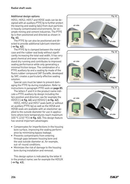
- Page 206 and 207: Radial shaft seals HDSA and HDSB ea
- Page 210 and 211: Radial shaft seals HSF fabric-reinf
- Page 212 and 213: Radial shaft seals HS split seals I
- Page 214 and 215: Radial shaft seals SKF Springlock T
- Page 216 and 217: Radial shaft seals Table 19 Standar
- Page 218 and 219: Radial shaft seals - HDS7 - metric
- Page 220 and 221: Radial shaft seals - HDS7 - inch di
- Page 222 and 223: Radial shaft seals - HDS7 - inch di
- Page 224 and 225: Radial shaft seals - HDS7K - metric
- Page 226 and 227: Radial shaft seals - HDS7K - inch d
- Page 228 and 229: Radial shaft seals - HDL - metric d
- Page 230 and 231: Radial shaft seals - HDL - inch dim
- Page 232 and 233: Radial shaft seals - HDL - inch dim
- Page 234 and 235: Radial shaft seals - HDL - inch dim
- Page 236 and 237: Radial shaft seals - HDL - inch dim
- Page 238 and 239: Radial shaft seals - HDL - inch dim
- Page 240 and 241: Radial shaft seals - HDL - inch dim
- Page 242 and 243: Radial shaft seals - HDL - inch dim
- Page 244 and 245: Radial shaft seals - HDS1, HDS2 and
- Page 246 and 247: Radial shaft seals - HDS1, HDS2 and
- Page 248 and 249: Radial shaft seals - HDS1, HDS2 and
- Page 250 and 251: Radial shaft seals - HDS1, HDS2 and
- Page 252 and 253: Radial shaft seals - HDS1, HDS2 and
- Page 254 and 255: Radial shaft seals - HDS1, HDS2 and
- Page 256 and 257: Radial shaft seals - HDS1, HDS2 and
- Page 258 and 259:
Radial shaft seals - HDS1, HDS2 and
- Page 260 and 261:
Radial shaft seals - HDS1K - inch d
- Page 262 and 263:
Radial shaft seals - HDS2K - metric
- Page 264 and 265:
Radial shaft seals - HDSF and HDSH
- Page 266 and 267:
Radial shaft seals - HDSA and HDSB
- Page 268 and 269:
Radial shaft seals - HDSA and HDSB
- Page 270 and 271:
Radial shaft seals - HDSA and HDSB
- Page 272 and 273:
Radial shaft seals - HDSE1 - metric
- Page 274 and 275:
Radial shaft seals - HDSD and HDSE
- Page 276 and 277:
Radial shaft seals - SBF - metric d
- Page 278 and 279:
Radial shaft seals - HSF1 (split) a
- Page 280 and 281:
Radial shaft seals - HSF1 (split) a
- Page 282 and 283:
Radial shaft seals - HSF1 (split) a
- Page 284 and 285:
Radial shaft seals - HSF1 (split) a
- Page 286 and 287:
Radial shaft seals - HSF1 (split) a
- Page 288 and 289:
Radial shaft seals - HSF1 (split) a
- Page 290 and 291:
Radial shaft seals - HSF1 (split) a
- Page 292 and 293:
Radial shaft seals - HSF2 (split) a
- Page 294 and 295:
Radial shaft seals - HSF3 (split) a
- Page 296 and 297:
Radial shaft seals - HSF3 (split) a
- Page 298 and 299:
Radial shaft seals - HSF3 (split) a
- Page 300 and 301:
Radial shaft seals - HSF4 (split) a
- Page 302 and 303:
Radial shaft seals - HSF9 - metric
- Page 304 and 305:
Radial shaft seals - HS4 and HS5 -
- Page 306 and 307:
Radial shaft seals - HS4 and HS5 -
- Page 308 and 309:
Radial shaft seals - HS6, HS7 and H
- Page 310 and 311:
Radial shaft seals - HS6, HS7 and H
- Page 312 and 313:
Radial shaft seals - HS6, HS7 and H
- Page 314 and 315:
Radial shaft seals - HS6, HS7 and H
- Page 316 and 317:
Radial shaft seals - HS6, HS7 and H
- Page 318 and 319:
Radial shaft seals - HS6, HS7 and H
- Page 320 and 321:
Radial shaft seals - HS6, HS7 and H
- Page 323 and 324:
Cassette seals General ............
- Page 325 and 326:
Design features All SKF Mudblock se
- Page 327:
Fig. 2 SKF Mudblock seal MUD5 Half
- Page 330 and 331:
Wear sleeves General To seal effici
- Page 332 and 333:
Wear sleeves SKF Speedi-Sleeve Gold
- Page 334 and 335:
Wear sleeves Fig. 6 Fig. 7 Fig. 8 I
- Page 336 and 337:
SKF Speedi-Sleeve - metric dimensio
- Page 338 and 339:
SKF Speedi-Sleeve - metric dimensio
- Page 340 and 341:
SKF Speedi-Sleeve - metric dimensio
- Page 342 and 343:
SKF Speedi-Sleeve - metric dimensio
- Page 344 and 345:
SKF Speedi-Sleeve - metric dimensio
- Page 346 and 347:
SKF Speedi-Sleeve - metric dimensio
- Page 348 and 349:
SKF Speedi-Sleeve - inch dimensions
- Page 350 and 351:
SKF Speedi-Sleeve - inch dimensions
- Page 352 and 353:
SKF Speedi-Sleeve - inch dimensions
- Page 354 and 355:
SKF Speedi-Sleeve - inch dimensions
- Page 356 and 357:
SKF Speedi-Sleeve - inch dimensions
- Page 358 and 359:
Wear sleeves Wear sleeves for heavy
- Page 360 and 361:
Wear sleeves Using LDSLV designs Th
- Page 362 and 363:
Wear sleeves for heavy industrial a
- Page 364 and 365:
Wear sleeves for heavy industrial a
- Page 366 and 367:
Wear sleeves for heavy industrial a
- Page 368 and 369:
Wear sleeves for heavy industrial a
- Page 370 and 371:
Wear sleeves for heavy industrial a
- Page 372 and 373:
Wear sleeves for heavy industrial a
- Page 375 and 376:
Track pin seals General ...........
- Page 377 and 378:
SKF Trackstar seals provide several
- Page 379:
Dimensions Spacer ring Bore Operati
- Page 382 and 383:
Metal face seals General SKF metal
- Page 384 and 385:
Metal face seals Permissible operat
- Page 386 and 387:
Metal face seals - HDDF - inch and
- Page 388 and 389:
Metal face seals - HDDF - inch and
- Page 391 and 392:
V-ring seals General ..............
- Page 393 and 394:
low but sufficient enough to mainta
- Page 395 and 396:
Main V-ring functions V-rings are s
- Page 397 and 398:
Sliding velocities V-rings can oper
- Page 399 and 400:
Counterface A fine-turned counterfa
- Page 401 and 402:
Shaft requirements Sharp edges, nic
- Page 403 and 404:
Dimensions Shaft diameter Seal insi
- Page 405 and 406:
Dimensions Shaft diameter Seal insi
- Page 407 and 408:
Dimensions Shaft diameter Seal insi
- Page 409 and 410:
Dimensions Shaft diameter Seal insi
- Page 411 and 412:
Dimensions Shaft diameter Seal insi
- Page 413 and 414:
Dimensions Shaft diameter Seal insi
- Page 415 and 416:
Dimensions Shaft diameter Seal insi
- Page 417 and 418:
Dimensions Shaft diameter Seal insi
- Page 419 and 420:
Dimensions Shaft diameter Seal insi
- Page 421 and 422:
Dimensions Shaft diameter Seal insi
- Page 423 and 424:
Dimensions Shaft diameter Seal insi
- Page 425 and 426:
Dimensions Shaft diameter Seal insi
- Page 427 and 428:
Dimensions Shaft diameter Seal insi
- Page 429 and 430:
Dimensions Shaft diameter Seal insi
- Page 431 and 432:
Dimensions Shaft diameter Seal insi
- Page 433 and 434:
Dimensions Shaft diameter Seal insi
- Page 435 and 436:
Dimensions Design Lip Shaft diamete
- Page 437 and 438:
Dimensions Design Lip Shaft diamete
- Page 439 and 440:
Dimensions Design Lip Shaft diamete
- Page 441 and 442:
Dimensions Design Lip Shaft diamete
- Page 443 and 444:
Dimensions Design Lip Shaft diamete
- Page 445 and 446:
Dimensions Design Lip Shaft diamete
- Page 447 and 448:
Dimensions Design Lip Shaft diamete
- Page 449 and 450:
Dimensions Design Lip Shaft diamete
- Page 451 and 452:
Dimensions Shaft diameter Seal insi
- Page 453 and 454:
Dimensions Shaft diameter Seal insi
- Page 455 and 456:
Dimensions Shaft diameter Seal insi
- Page 457 and 458:
Dimensions Shaft diameter Seal insi
- Page 459 and 460:
Dimensions Shaft diameter Seal insi
- Page 461 and 462:
Dimensions Shaft diameter Seal insi
- Page 463 and 464:
Dimensions Shaft diameter Seal insi
- Page 465 and 466:
Dimensions Shaft diameter Seal insi
- Page 467 and 468:
Installation The inside diameter of
- Page 469 and 470:
Dimensions Shaft Case outside Seal
- Page 471:
469 7.4
- Page 474 and 475:
Axial clamp seals General SKF axial
- Page 476 and 477:
Axial clamp seals Installation inst
- Page 478 and 479:
Axial clamp seals - CT1 and CT4 - m
- Page 480 and 481:
Axial clamp seals - CT1 and CT4 - m
- Page 482 and 483:
Axial clamp seals - CT1 and CT4 - i
- Page 484 and 485:
Product index Design Product group
- Page 486:
Design Product group Product table